US1852411A - Automatic shotgun - Google Patents
Automatic shotgun Download PDFInfo
- Publication number
- US1852411A US1852411A US546574A US54657431A US1852411A US 1852411 A US1852411 A US 1852411A US 546574 A US546574 A US 546574A US 54657431 A US54657431 A US 54657431A US 1852411 A US1852411 A US 1852411A
- Authority
- US
- United States
- Prior art keywords
- barrel
- latch
- spring
- breech block
- frame
- Prior art date
- Legal status (The legal status is an assumption and is not a legal conclusion. Google has not performed a legal analysis and makes no representation as to the accuracy of the status listed.)
- Expired - Lifetime
Links
Images


Classifications
-
- F—MECHANICAL ENGINEERING; LIGHTING; HEATING; WEAPONS; BLASTING
- F41—WEAPONS
- F41A—FUNCTIONAL FEATURES OR DETAILS COMMON TO BOTH SMALLARMS AND ORDNANCE, e.g. CANNONS; MOUNTINGS FOR SMALLARMS OR ORDNANCE
- F41A9/00—Feeding or loading of ammunition; Magazines; Guiding means for the extracting of cartridges
- F41A9/01—Feeding of unbelted ammunition
- F41A9/06—Feeding of unbelted ammunition using cyclically moving conveyors, i.e. conveyors having ammunition pusher or carrier elements which are emptied or disengaged from the ammunition during the return stroke
- F41A9/09—Movable ammunition carriers or loading trays, e.g. for feeding from magazines
- F41A9/10—Movable ammunition carriers or loading trays, e.g. for feeding from magazines pivoting or swinging
- F41A9/13—Movable ammunition carriers or loading trays, e.g. for feeding from magazines pivoting or swinging in a vertical plane
- F41A9/16—Movable ammunition carriers or loading trays, e.g. for feeding from magazines pivoting or swinging in a vertical plane which is parallel to the barrel axis
- F41A9/17—Movable ammunition carriers or loading trays, e.g. for feeding from magazines pivoting or swinging in a vertical plane which is parallel to the barrel axis mounted within a smallarm
- F41A9/18—Movable ammunition carriers or loading trays, e.g. for feeding from magazines pivoting or swinging in a vertical plane which is parallel to the barrel axis mounted within a smallarm feeding from a tubular magazine under the barrel
-
- F—MECHANICAL ENGINEERING; LIGHTING; HEATING; WEAPONS; BLASTING
- F41—WEAPONS
- F41A—FUNCTIONAL FEATURES OR DETAILS COMMON TO BOTH SMALLARMS AND ORDNANCE, e.g. CANNONS; MOUNTINGS FOR SMALLARMS OR ORDNANCE
- F41A17/00—Safety arrangements, e.g. safeties
- F41A17/46—Trigger safeties, i.e. means for preventing trigger movement
- F41A17/48—Automatically operated trigger safeties, i.e. operated by breech opening or closing movement
-
- F—MECHANICAL ENGINEERING; LIGHTING; HEATING; WEAPONS; BLASTING
- F41—WEAPONS
- F41A—FUNCTIONAL FEATURES OR DETAILS COMMON TO BOTH SMALLARMS AND ORDNANCE, e.g. CANNONS; MOUNTINGS FOR SMALLARMS OR ORDNANCE
- F41A3/00—Breech mechanisms, e.g. locks
- F41A3/12—Bolt action, i.e. the main breech opening movement being parallel to the barrel axis
- F41A3/36—Semi-rigid bolt locks, i.e. having locking elements movably mounted on the bolt or on the barrel or breech housing
- F41A3/38—Semi-rigid bolt locks, i.e. having locking elements movably mounted on the bolt or on the barrel or breech housing having rocking locking elements, e.g. pivoting levers or vanes
- F41A3/40—Semi-rigid bolt locks, i.e. having locking elements movably mounted on the bolt or on the barrel or breech housing having rocking locking elements, e.g. pivoting levers or vanes mounted on the bolt
-
- F—MECHANICAL ENGINEERING; LIGHTING; HEATING; WEAPONS; BLASTING
- F41—WEAPONS
- F41A—FUNCTIONAL FEATURES OR DETAILS COMMON TO BOTH SMALLARMS AND ORDNANCE, e.g. CANNONS; MOUNTINGS FOR SMALLARMS OR ORDNANCE
- F41A5/00—Mechanisms or systems operated by propellant charge energy for automatically opening the lock
- F41A5/02—Mechanisms or systems operated by propellant charge energy for automatically opening the lock recoil-operated
Definitions
- the device forming the subject matter of this ap lication is a recoil-operated gun
- breech block and the barrel may have relative movement in connection with each other, thereby reducing the movement of the barrel and improvin the balance of the gun as it is handle in shooting.
- Another objectof the invention is to 1mprove the means whereby the several instrume'ntalities which transfer of the shell, operate the lock between the breech blockand the barrel, and bring about the firing, may be caused to act in properly timed relation.
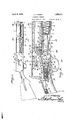
- FIG. 1 shows in side elevation, a device constructed in accordance with the invention
- Figure 2 is a longitudinal section
- Figure 3 is a longitudinal section showing the opposite side of the gun from that delineated in Figure 2;
- Figure 4 is a section at right angles to the cutting plane in Figure 3;
- Figure 5 is a longitudinal section showing the parts in positions difierent from those disclosed in Figure 4; V t
- Figure 6 is a sectional view showing the parts as they will appear when the gun is opened;
- Figure 7 is a sectional view showin the.
- Figure 15 is a transverse section on the line 15-15 of Figure 2;
- Figure 16 is a perspective view showing one of the latches
- Figure 17 is i a perspective view showing another of the latches
- Figure 18 is a perspective view showing the rear portion of the barrel
- Figure 19 is a perspective view of the hammer
- Figure 20 is a perspective view of the guide block
- Fi ure 21 is a perspective view of the thrust mem er
- Figure 22 is a perspective view of firing pin
- Figure 23 is a perspective view of the carrier
- Figure 24 is a perspective view showing one of thelatches
- Figure 25 is a breech block
- Figure 26 is a perspective view of the slide
- Figure 27 is a perspective view of the lockin member
- igure 28 is a perspective view disclosing the rear end of the barrel.
- FIG. 1 perspective view of the to fragmental longitudinal sec- '
- the frame of the gun is marked by the numeral 1, and carries the stock, which mabe considered to be part of the frame.
- barrel 2 is mounted to slide longitudinally in the forward end of the frame 1 and ⁇ has ribs 3 (Figures 28 and 18) slidablein longitudinal rooves 4 ( Figures 5 and 13) formed in the frame 1.
- the magazine appears at 5, and has its rear end (Fi ures 2 and 7) mounted in the forward end the frame 1.
- a follower 6 ( Figure 2) is slidable in magazine 5, and is pressed rearwardly by the usual spring 7.
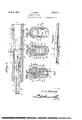
- a rear spring 19 (Figure 1) surrounds the magazine and abuts at its rear end against the forward end of the frame 1.
- a front or supplemental s ring 20 surrounds the forward portion 0 the magazine 5 and is weaker than the rear spring 19.
- Lugs 21 ( Figures 1 and 11) are secured to opposlte sides of the magazine 5, and are interposed between the inner ends of the springs 19 and 20.
- the barrel2 carries a depending ring 22 ( Figures 1 and 11), surrounding the magazine 5 and interposed between the inner ends of the springs 19 and 20.
- the forearm 8 receives both the rear end of the barrel 2 and the magazine 5, the forearm being provided at its forward end with a bushing 23 ( Figures 1 and 12) for the slidable mounting of the barrel 2.
- the forward end of the spring 20 is engaged with the forward portion of the forearm 8.
- a cap 9 ( Figure 1) is threaded on the forward end of the magazine 5 and holds the forearm 8 in place, the rear end of the forearm abutting against the forward end of the frame 1( Figure 5) and having projections 10 engaged with the frame.
- the forearm 8 extends around the barrel 2 and keeps the hand of the shooter from coming into contact with the hot apelre the forearm preferably bein made of woo or some other material w'hic will not conductheat readily.
- Figuresz28 and 3 show that there is :an opening 11' in one side of the barrel 2, at the rear end thereof, and this opening forms a shoulder 12 in the barrel, there being a notch 14 in the shoulder, at one :side of 'the barrel.
- the barrel 2 At its rear end, the barrel 2 has an inwardly projecting lug 16, which is used in throwing out the shell. There is a notch 17 in the rear end of the barrel 2, and on 'one side, the barrel has agroove which ends in a cam surface 18, to be seen in Figures 18, 9 and 7.
- latches 24 and 25 are shown, the latch 24 appearing in detail in Figure 16, and the latch 25 appearing in detail in Figure 17.
- the latches 24 and 25 are located at the rear end of the magazine 5, and
- the forward end of the latch 24 is carried inwardly by a spring 27, and the rear end of glge latch 25 is carried inwardly by a spring
- the forward end of the latch 25 can be tilted inwardly, and the rear end of the latch can be tilted outwardly, by a button 29 on the latch, the button extending outwardly through the side of the frame 1.
- the latch 24 has an upstanding projection 30 (Figure 16), provided with a notch 31 in its inner edge, theproj'ection 30 carrying a cam surface 32, which is adapted to cooperate with the cam 18 of the barrel 2.
- a latch 33 to be seen in F igure 6, is fulcrumed at 34, intermediate its ends, on the frame of the gun.
- a spring 35 tends to elevate the forward end of the latch 33 so that the latch will. engage the rear end of the left hand rib 3 ( Figure 28) on the barrel 2 and hold the barrel against movement to the left in Figure 6, when the barrel has been moved to the right in that figure, the gun then being opened.
- the latch 33 swings in a plane at right angle to the plane in which the latches 24 and 25 operate, and the notch 31 ( Figure 16) on the projection 30 of the latch 24 is for the accommodation of the latch 33.
- the means for swinging the latch 33 from the position of Figure 6 to the position of Figure 3, out of engagement with the barrel 2, is somewhat remote from parts now under discussion, and that means will alluded to at a more convenient place.
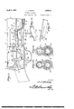
- a breech block 36 ( Figure '25) is mounted to slide .in the frame 1, the breech block 'having lateral ribs-37 which are received ( Figure 13) in the longitudinal grooves 4 of the frame 1.
- the breech block 36 has a channel 103, and is provided at its rear end with an upstanding lug 38 adapted to be received in the notch 17 which is formed in the rear end of the barrel 2.
- the breech block 36 has an inside shoulder 108, and a depending rear lug 116.
- the breech block 36 operates beneath the overhanging rear portion of the barrel 2 in Figure 28, and is adapted to cooperate with the shoulder 12, to retain a shell in the barrel when the gun is in firing condition.
- a spring-actuated shell catch 39' is mounted on the forward end of the breech block 36 and is adapted to be received in the notch 14 of the barrel 2.
- the breech block 36 has a recess 40 in its top, and is provided with arcuate grooves 41 which open into the recess 40.
- a slide 42 ( Figure 26) is received in a uidewa 43 in the breech block 36 and is provlded at its rear end with a downwardlyextended shoulder 107 having a cam surface on its rear end.
- the slide 42 is provided on its inner side with a projection 101.
- the locking member 47 has an upstandits opposite side, the slide 42 11am an outstandin fingerpiece 44 connected the bar 33 by a re uced neck 102.
- the fingerplece 44 is adapted to move in the openin 45 1) in the frame 1, through wlnch is ejected, and when the bar 42 1S pulled back wardly by hand, the neck 102 of the fingerpiece is received in a slot 46 in the frame 1.
- Figure 27 shows a locking member 47 that is received in the recess 40 of the breech block ( Figure ing nose 49, adapted to be received in the seat 15 ( Figure 28) of the barrel 2, to connect the breech block 36 to the barrel.
- the lockin member 47 has a slot 104 in .its lower en On its lower edge, the locking member 47 has a shoulder 50. On its sides, the locking member 47 is provided with arcuate ribs 48 received in the grooves 41 of the breech block "36, to afford a pivotal connection between the locking member and thebreech block.
- FIG 21 there is'shown a thrust member 51, which is pivoted at 52 to the locking member 47.
- the thrust member 51 has. a lateral stud 106 ( Figures 4, 7 and 8).
- the thrust member 51 has an offset 53 at one side, which cooperates with the projection.
- the thrust member 51 is equipped with a shoulder 54.
- the reduced rear end of the thrust member 51 slides in a guide 55 on the frame of the gun ( Figure 2) and engages a head 56 on the forward end of a compression spring 57 mounted in the gun frame, the head 56 being held for sliding movement in the frame.
- a latch 58 ( Figure 24) is pivotally mount-- ed at 59 ( Figure 2) on the breech block 36 and is provided at its rear end with a fork 60.
- a compression spring 61 1 interposed between the forward end of the latch 58 and block 36, into the path of the cam 100 (Figme 28) on the barrel 2.
- a carrier 64 (Figure 23) extends lengthwise of the gun and has its forward end disposed adjacent to the follower 6 ( Figure 2) in the magazine 5.
- Pivot elements 65 are mounted in the frame 1 and support the carrier 64 for swinging movement.
- a spring 66 ( Figure 7) is mounted on the frame 1 and engages the rear end of the carrier 64, to swing it downwardly against the trigger guard 67 which may be considered as part of the frame, so far as stopping the downward swinging movement of the carrier is concerned.
- projection 68 On one side of the carrier 64 there is projection 68 which, as shown in Figure 14, moves in a slot 69 in the frame 1, the slot being of arouate form, and enabling the projection. 68
- the shell move upwardly cooperate with the latch A'latch Figures 23, 6 and 3) is pivoted at 71 to t 9 rear end of the carrier 64, and abuts'at 72 ( Figure 3) a ainst the carrier 64 under the action of a p unger 73 slidable in the rear end of the carrier 64 and imelled rearwardly by a compression spring 4.
- Afiring pin 75 ( Figures 2 and 22) has sliding movement in the breech block 36, the reduced forward end of the firing pin sliding in the forward portion of the breech block the firing pin bemg supplied at its rear end with a rectangular enlargement 78 that slides in the channel 103 ( Figure 25) of the breech bloc
- the enlargement 78 has a notch 77 receiving a cross pin 79 ( Figure 2) mounted 1n the rear part of the breech block 36, and
- a guide block 80 ( Figure 20) is secured in I frame of the gun, and has an upper channel 81 and a lower channel 82: In the rear end of the guide block 80 there is whole 83 which may receive a stem 84 on a, hammer 85 ( Figure 19) which is adapted to advance and strike the depending arm 76 of the firing pin.
- the hammer 85 has an upper arm 86, slidable in the channel 81 of the guide block 80, and a lower arm 87, which is slidable in the channel 82 of the guide block.
- Acompression spring 88 ( Figure 2) surrounds the stem against the rear end of the guide block 80, the forward end 'of the spring abutting against an enlargement 89 on the stem 84, the said enlargement being slidabledn a bore 90 in the guide block.
- the function of the spring 88 is to advance the hammer 85. 4
- Either of a pair of spring-pressed detents 91, pivoted to-the lower arm 87 of the hammer 85 ( Figure 2) are adapted to engage with the trigger 92, which is pivotally mounted on the trigger guard 67.
- the trigger 92 has a lateral projection 105 ( Figure 8).
- a safety lock 93 is slidable on the trigger guard 67, and may be engaged with the trigger 90, at the will of anoperator, in a manner which will be understood readily from Figure 2.
- a standard 94 ( Figures 7, 8 and 10) is erected on the frame 1, to one side of the trigger 92, and in the upper end of the standard, afixed pivot element 95 is mounted.
- a bell crank lever 96 is mounted to swing a spring strip 97 being secured to the lower end connected to the depending'arm of. the bell 84 and abuts at one end pivot element 95, and having its crank lever 96.
- crank lever 96 carries an upwardlyextendedof the depending arm of the bell crank lever lies above the lateral projection 105 on the trigger 92.
- the depending arm of the bell spring finger 98 located in the pathof the outwardly projecting stud 106 on thejthrust member 51.
- a latch 111 ( Figure 7 extends lengthwise of the gun, and is fulcrumedat 112, intermediate its ends, on the gun frame.
- a bowed spring 114 is connected at its forward end to the latch 111 and at its rear end to the frame. The tendency of-the spring 114 is to throw the forward end of the latch 111 down, clear of one of the ribs 3 on the barrel 2, but when the piece is in firing condition, one of the ribs 37 on the breech block 36 engages above the bowed spring 114, and throws the front end of the latch 111 up in front of the said rib 3 on the barrel.
- the spring 20 of Figure 1 is not strong enough to resist the forward movement of the barrel 2, if the gun is picked up by the barrel, but the latch 111, in the position of Figure -7, does prevent the forward sliding movement of the barrel under the conditions stated.
- the latch 111 has to be depressed from the. position of Fi ure 7, so that the barrel 2 can move forward, uring the loading operation, but it will be most convenient to describe the loading operation first, as though the latch 111 did not exist, and after the loading operation-has been described, it can be better pointed out how the latch 111 is got out of the way, to let the barrel 2 move forward.
- the thrust member 51 compressing the spring 57 and the spring 19.
- the cam surface 115 on the slide 42 moves over the latch 7 O on the carrier 64, the latch yields backwardly, the spring 7 4 of Figure 3 being compressed.
- the upper. end of the latch 70 then snaps in front of the shoulder 107 on the slide 42, as in Figure 6, and holds back the slide, relieving-the thrust .of the spring 57 on the member 51, because the back end of the slide is against the offset 53 on the member 51.
- The'barrel 2 and the breech block 36 move forward, because they are held together by the nose 49 on the locking member 47, and
- the breech block36 moves forwardly a little way, independently of the slide 42.
- This independent movement swings the locking member 47 down on its pivot 52, and withdraws the nose 49 of the locking member from the seat 15 in the barrel, since the lockmember 47 is connected to the thrust member51, which, at this time, is held back by the trigger on the carrier 64.
- the shoulder 50 on the locking member 49 engages 'the back end or fork 60 of'the latch of the locking member out of engagement with the barrel 2, because the lower end of the locking member 49 has engaged the shoulder 108 on the breech block 36 ( Figure 25).
- the barrel 2 moves forward under the action of the spring 19, and the ring 22 on the barrel compresses thespring 20, the latch 33 snapping behind one rib 3 of the barrel 2,
- the cam 18 on the barrel engages the part 32 on the latch 24 and withdraws the latch from theshell inthe magazine 5.
- the shell moves back on the carrier 64 under the action of the spring 7, and tilts the latch 25 inwardly at its forward. end, to hold back the next shell in advance, the rear end of the latch 25 being withdrawn from above the carrier 64, so that the carrier can swing upwardly, with the shell upon it.
- the thrust member 51 is pushed forward by the spring 57, and, through the shoulder 53, the slide 42, and the latch 7 O, tilts the carrier 64 upwardly about the pivot point 65, the shell being raised into alignment with the barrel 2.
- the projection 68 on the carrier moves in the slot 69 of the frame and tilts the latch 33 clear of the rib 3 on the barrel 2, so that the barrel. can move backwardly, under the action of the spring 20, which does not have to Work against the stronger spring 19, because the spring 19 is held back by the lugs 21 on the magazine 5.
- the function of the lug 116 is to kee the trigger 92 from being pulled until ackward movement of the breech block 36 with respect to slide 42 has moved the locking member 47 to the position of Figure 2, into engagement with the barrel.
- the operator can ring about, by hand, the necessar relative movement between the slide an the breech block, which will withdraw the nose 49 of the locking menn ber 47 from the seat 15 of the barrel 2, and permit a manual 0 ening of the gun.
- a gun a frame, a barrel and a. breech block having backward right line sliding the action of the stud 106 on the thrust mem movement in the frame together, under re- 1 coil; a first spring-actuated means for advancing the breech block; a second spring means rendered active by recoil to advance the barrel; mechanism for holding back the breech block, against the action of the first spring-actuated means, while the barrel is moving forward under the action of the second spring means; a third spring means rendered active by the advancing barrel to move the barrel backwardly; and means for releasing said mechanism to permit the breech block to move forwardand meet the backwardly moving barrel.
- a gun constructed as set forth in claim 1, in combination with a latch on the frame and engaging the barrel tohold the barrel temporarily advanced, against the action of the third spring means, a part of the mechanism for holding back the breech block cooperating with the-latch to disengage the latch from the barrel.
- a gun constructed as set forth in claimlock and slidable in the frame; a spring means for advancing the thrust member; a slide having limited movement on the breech block, the slide engaging the thrust member to hold back the thrust member, the releasing means cooperating with the slide; the limited movement between the breech block and the slide permitting the breech block to move forward with respect to the slide for a limited time, with the barrel, and said limited forward movement of the breech block withdrawing the lock from engagement with the barrel.
- a gun constructed as set forth in claim 1, and further characterized by the fact that the means for releasing said mechanism em- 4 engaging the detent and disengaging it from acting upon the carrier first to raise the carrier and then to cause the ,carrier to clear the first spring-actuatedmeans, spring means for depressing the carrier, a latch on the frame and holding the carrier against upward movement, and a shell ma azine on the frame, the latch lying in the pat of a shell moving out of the magazine and upon the carrier.
- a gun constructed as set forth in claim 1 in combination with a firing device mov-- able on the breech block, a hammer movable on the frame, means for moving the hammer to actuate the firing device, a trigger on the frame and controlling the hammer, and a de tent movably mounted on the frame and engaging the trigger to keep the trigger from being pulled, the first spring-actuated means the trigger as the first spring-actuated means is advanced.
- a gun constructed as set forth in claim 1, and further characterized by the fact that the first spring-actuated means embodies a lock pivoted to the breech block and engaging V the barrel; a thrust member pivoted to the lock and slidable in the frame; spring means for advancing the thrust member; a slide having limited movement on the breech block, the slide engaging the thrust member to hold back the thrust member.
- the releasing means cooperating with the slide, the limited movement between the breech block and the slide permitting the breech block 'to move forward with respect to the slide for a limited time, with the barrel, and said limited forward movement of the breech block withdrawing the lock from engagement with the barrel,
- a trigger for the gun a detent movable upon the frame and engaging the tri 'ger to prevent the trigger from belng pulled and means on the breech block for engaging the 'detent and disengaging it from the trigger when said limited movement of the breech block is in a backward direction during the closing of the gun.
Description
April 5, 1932. J. HENRY AUTOMATIC SHOTGUN Filed June 24, 1931 6 Sheets-Sheet l April 5, 1932. J. J. HENRY AUTOMATIC SHOTGUN Filed June 24, 1931 6 Sheets-Sheet 2 A ril 5, 1932. J. J. HENRY AUTOMATIC SHOTGUN Filed June 24, 1931 6 Sheets-Sheet 3 J. J. HENRY AUTOMATIC SHOTGUN April 5, 1932.
Filed June 24, 1931 6 Sheets-Sheet 4 April 5, 1932. J. J. HENRY AUTOMATIC SHOTGUN 6 Sheets-Sheet 5 Filed June 24, 1931 April 5, 1932. J. J. H ENR Y AUTOMATIC SHOTGUN Filed June 24, 1951 6 Sheets-Sheet 6 Patented Apr. 5, 1932 JOHN J. HENRY, or mason, rumors; Assmuon or orqnmur 'ro HARRY n. ocommml, or EFFINGHAM, mmors AUTOMATIC SHOTGUN Application filed June 24, 1931, seen No. 546,574.
The device forming the subject matter of this ap lication is a recoil-operated gun,
and one ject of the invention is to pro.- vide novel means whereby the breech block and the barrel may have relative movement in connection with each other, thereby reducing the movement of the barrel and improvin the balance of the gun as it is handle in shooting.
Another objectof the invention is to 1mprove the means whereby the several instrume'ntalities which transfer of the shell, operate the lock between the breech blockand the barrel, and bring about the firing, may be caused to act in properly timed relation.
It is within the province of the disclosure to improve generally and to enhance the utility of devices of that type to which the invention appertains.
With the above and other objects in view, which will appear as the description proceeds, the invention resides inthe combination and arrangement of parts and in the details of construction hereinafter described v and claimed, it being understood that changes in the precise embodiment of the invention herein disclosedfinay be made within the scope of what is claimed, without departing from the spirit of the invention.-
In the accompanying drawings Figure 1 shows in side elevation, a device constructed in accordance with the invention;
Figure 2 is a longitudinal section;
Figure 3 is a longitudinal section showing the opposite side of the gun from that delineated in Figure 2;
Figure 4 is a section at right angles to the cutting plane in Figure 3; 3,
Figure 5 is a longitudinal section showing the parts in positions difierent from those disclosed in Figure 4; V t
Figure 6 is a sectional view showing the parts as they will appear when the gun is opened;
in Figure 6;
Figure 7 is a sectional view showin the.
opposite side of the gun from view taken adj acent' line 1414 of Figure 2;
Figure 15 is a transverse section on the line 15-15 of Figure 2;
Figure 16 is a perspective view showing one of the latches;
Figure 17 is i a perspective view showing another of the latches;
Figure 18 is a perspective view showing the rear portion of the barrel;
Figure 19 is a perspective view of the hammer;
Figure 20 is a perspective view of the guide block;
Fi ure 21 is a perspective view of the thrust mem er;
Figure 22 is a perspective view of firing pin; v
Figure 23 is a perspective view of the carrier;
Figure 24 is a perspective view showing one of thelatches;
Figure 25 is a breech block;
Figure 26 is a perspective view of the slide;
Figure 27 is a perspective view of the lockin member;
perspective view of the to fragmental longitudinal sec- 'The frame of the gun is marked by the numeral 1, and carries the stock, which mabe considered to be part of the frame. barrel 2 is mounted to slide longitudinally in the forward end of the frame 1 and\has ribs 3 (Figures 28 and 18) slidablein longitudinal rooves 4 (Figures 5 and 13) formed in the frame 1. The magazine appears at 5, and has its rear end (Fi ures 2 and 7) mounted in the forward end the frame 1. A follower 6 (Figure 2) is slidable in magazine 5, and is pressed rearwardly by the usual spring 7.
' A rear spring 19 (Figure 1) surrounds the magazine and abuts at its rear end against the forward end of the frame 1. A front or supplemental s ring 20 surrounds the forward portion 0 the magazine 5 and is weaker than the rear spring 19. Lugs 21 (Figures 1 and 11) are secured to opposlte sides of the magazine 5, and are interposed between the inner ends of the springs 19 and 20. The barrel2 carries a depending ring 22 (Figures 1 and 11), surrounding the magazine 5 and interposed between the inner ends of the springs 19 and 20. p v
The forearm 8 receives both the rear end of the barrel 2 and the magazine 5, the forearm being provided at its forward end with a bushing 23 (Figures 1 and 12) for the slidable mounting of the barrel 2. The forward end of the spring 20 is engaged with the forward portion of the forearm 8. A cap 9 (Figure 1) is threaded on the forward end of the magazine 5 and holds the forearm 8 in place, the rear end of the forearm abutting against the forward end of the frame 1( Figure 5) and having projections 10 engaged with the frame. The forearm 8 extends around the barrel 2 and keeps the hand of the shooter from coming into contact with the hot bazrre the forearm preferably bein made of woo or some other material w'hic will not conductheat readily.
Figuresz28 and 3 show that there is :an opening 11' in one side of the barrel 2, at the rear end thereof, and this opening forms a shoulder 12 in the barrel, there being a notch 14 in the shoulder, at one :side of 'the barrel. In
the lower edge of the overhanging rear'part of the barrel 2 there is a cam 100, and in the top of the overhan 'ng rear part of the barrel there is a seat 15 fir the locking mechanism that holds the barrel and the breech block together, as will be described hereinafter. At its rear end, the barrel 2 has an inwardly projecting lug 16, which is used in throwing out the shell. There is a notch 17 in the rear end of the barrel 2, and on 'one side, the barrel has agroove which ends in a cam surface 18, to be seen in Figures 18, 9 and 7. Referring to Figure 4, latches 24 and 25 are shown, the latch 24 appearing in detail in Figure 16, and the latch 25 appearing in detail in Figure 17. The latches 24 and 25 are located at the rear end of the magazine 5, and
are pivotally mounted, as shown at 26, intermediate their ends, on the frame 1 of the gun. The forward end of the latch 24 is carried inwardly by a spring 27, and the rear end of glge latch 25 is carried inwardly by a spring To release a shell from the magazine 5 by hand, after the latch 24 has been moved to inoperative position by the cam 18, the forward end of the latch 25 can be tilted inwardly, and the rear end of the latch can be tilted outwardly, by a button 29 on the latch, the button extending outwardly through the side of the frame 1. The latch 24 has an upstanding projection 30 (Figure 16), provided with a notch 31 in its inner edge, theproj'ection 30 carrying a cam surface 32, which is adapted to cooperate with the cam 18 of the barrel 2. A latch 33, to be seen in F igure 6, is fulcrumed at 34, intermediate its ends, on the frame of the gun. A spring 35 tends to elevate the forward end of the latch 33 so that the latch will. engage the rear end of the left hand rib 3 (Figure 28) on the barrel 2 and hold the barrel against movement to the left in Figure 6, when the barrel has been moved to the right in that figure, the gun then being opened. The latch 33 swings in a plane at right angle to the plane in which the latches 24 and 25 operate, and the notch 31 (Figure 16) on the projection 30 of the latch 24 is for the accommodation of the latch 33. The means for swinging the latch 33 from the position of Figure 6 to the position of Figure 3, out of engagement with the barrel 2, is somewhat remote from parts now under discussion, and that means will alluded to at a more convenient place.
A breech block 36 (Figure '25) is mounted to slide .in the frame 1, the breech block 'having lateral ribs-37 which are received (Figure 13) in the longitudinal grooves 4 of the frame 1. The breech block 36 has a channel 103, and is provided at its rear end with an upstanding lug 38 adapted to be received in the notch 17 which is formed in the rear end of the barrel 2. The breech block 36 has an inside shoulder 108, and a depending rear lug 116. The breech block 36 operates beneath the overhanging rear portion of the barrel 2 in Figure 28, and is adapted to cooperate with the shoulder 12, to retain a shell in the barrel when the gun is in firing condition. A spring-actuated shell catch 39' is mounted on the forward end of the breech block 36 and is adapted to be received in the notch 14 of the barrel 2. The breech block 36 has a recess 40 in its top, and is provided with arcuate grooves 41 which open into the recess 40. A slide 42 (Figure 26) is received in a uidewa 43 in the breech block 36 and is provlded at its rear end with a downwardlyextended shoulder 107 having a cam surface on its rear end. The slide 42 is provided on its inner side with a projection 101. On
I 36. The locking member 47 has an upstandits opposite side, the slide 42 11am an outstandin fingerpiece 44 connected the bar 33 by a re uced neck 102. The fingerplece 44 is adapted to move in the openin 45 1) in the frame 1, through wlnch is ejected, and when the bar 42 1S pulled back wardly by hand, the neck 102 of the fingerpiece is received in a slot 46 in the frame 1.
Figure 27 shows a locking member 47 that is received in the recess 40 of the breech block (Figure ing nose 49, adapted to be received in the seat 15 (Figure 28) of the barrel 2, to connect the breech block 36 to the barrel. The lockin member 47 has a slot 104 in .its lower en On its lower edge, the locking member 47 has a shoulder 50. On its sides, the locking member 47 is provided with arcuate ribs 48 received in the grooves 41 of the breech block "36, to afford a pivotal connection between the locking member and thebreech block.
In Figure 21 there is'shown a thrust member 51, which is pivoted at 52 to the locking member 47. The thrust member 51 has. a lateral stud 106 (Figures 4, 7 and 8). The thrust member 51 has an offset 53 at one side, which cooperates with the projection.
101 on the slide 42, to hold the bar on the breech block 36'for limited sliding movement thereon. In its lower edge, the thrust member 51 is equipped with a shoulder 54. The reduced rear end of the thrust member 51 slides in a guide 55 on the frame of the gun (Figure 2) and engages a head 56 on the forward end of a compression spring 57 mounted in the gun frame, the head 56 being held for sliding movement in the frame.
A latch 58 (Figure 24) is pivotally mount-- ed at 59 (Figure 2) on the breech block 36 and is provided at its rear end with a fork 60. A compression spring 61 1s interposed between the forward end of the latch 58 and block 36, into the path of the cam 100 (Figme 28) on the barrel 2. v 1,
A carrier 64 (Figure 23) extends lengthwise of the gun and has its forward end disposed adjacent to the follower 6 (Figure 2) in the magazine 5.
Pivot elements 65 (Figure 4) are mounted in the frame 1 and support the carrier 64 for swinging movement. A spring 66 (Figure 7) is mounted on the frame 1 and engages the rear end of the carrier 64, to swing it downwardly against the trigger guard 67 which may be considered as part of the frame, so far as stopping the downward swinging movement of the carrier is concerned. On one side of the carrier 64 there is projection 68 which, as shown in Figure 14, moves in a slot 69 in the frame 1, the slot being of arouate form, and enabling the projection. 68
the shell move upwardly cooperate with the latch A'latch Figures 23, 6 and 3) is pivoted at 71 to t 9 rear end of the carrier 64, and abuts'at 72 (Figure 3) a ainst the carrier 64 under the action of a p unger 73 slidable in the rear end of the carrier 64 and imelled rearwardly by a compression spring 4. Afiring pin 75 (Figures 2 and 22) has sliding movement in the breech block 36, the reduced forward end of the firing pin sliding in the forward portion of the breech block the firing pin bemg supplied at its rear end with a rectangular enlargement 78 that slides in the channel 103 (Figure 25) of the breech bloc The enlargement 78 has a notch 77 receiving a cross pin 79 (Figure 2) mounted 1n the rear part of the breech block 36, and
A guide block 80 (Figure 20) is secured in I frame of the gun, and has an upper channel 81 and a lower channel 82: In the rear end of the guide block 80 there is whole 83 which may receive a stem 84 on a, hammer 85 (Figure 19) which is adapted to advance and strike the depending arm 76 of the firing pin.
75. The hammer 85 has an upper arm 86, slidable in the channel 81 of the guide block 80, and a lower arm 87, which is slidable in the channel 82 of the guide block.
Acompression spring 88 (Figure 2) surrounds the stem against the rear end of the guide block 80, the forward end 'of the spring abutting against an enlargement 89 on the stem 84, the said enlargement being slidabledn a bore 90 in the guide block. The function of the spring 88 is to advance the hammer 85. 4
Either of a pair of spring-pressed detents 91, pivoted to-the lower arm 87 of the hammer 85 (Figure 2) are adapted to engage with the trigger 92, which is pivotally mounted on the trigger guard 67. The trigger 92 has a lateral projection 105 (Figure 8). A safety lock 93 is slidable on the trigger guard 67, and may be engaged with the trigger 90, at the will of anoperator, in a manner which will be understood readily from Figure 2.
A standard 94 (Figures 7, 8 and 10) is erected on the frame 1, to one side of the trigger 92, and in the upper end of the standard, afixed pivot element 95 is mounted. On the pivot element 95, a bell crank lever 96 is mounted to swing a spring strip 97 being secured to the lower end connected to the depending'arm of. the bell 84 and abuts at one end pivot element 95, and having its crank lever 96. The lower end;
crank lever 96 carries an upwardlyextendedof the depending arm of the bell crank lever lies above the lateral projection 105 on the trigger 92. The depending arm of the bell spring finger 98 located in the pathof the outwardly projecting stud 106 on thejthrust member 51.
A latch 111 (Figure 7 extends lengthwise of the gun, and is fulcrumedat 112, intermediate its ends, on the gun frame. A bowed spring 114 is connected at its forward end to the latch 111 and at its rear end to the frame. The tendency of-the spring 114 is to throw the forward end of the latch 111 down, clear of one of the ribs 3 on the barrel 2, but when the piece is in firing condition, one of the ribs 37 on the breech block 36 engages above the bowed spring 114, and throws the front end of the latch 111 up in front of the said rib 3 on the barrel. The spring 20 of Figure 1 is not strong enough to resist the forward movement of the barrel 2, if the gun is picked up by the barrel, but the latch 111, in the position of Figure -7, does prevent the forward sliding movement of the barrel under the conditions stated. The latch 111 has to be depressed from the. position of Fi ure 7, so that the barrel 2 can move forward, uring the loading operation, but it will be most convenient to describe the loading operation first, as though the latch 111 did not exist, and after the loading operation-has been described, it can be better pointed out how the latch 111 is got out of the way, to let the barrel 2 move forward.
When the trigger 92 is pulled, it is disengaged from the hammer 85, the hammer moving forwardly under the action of the spring 88, the hammer striking the arm 76 of the firing pin 75, and advancing the firing pin to explode the shell. The recoil carries the barrel 2 and breech block 36 back together,
the thrust member 51 compressing the spring 57 and the spring 19. As the breech block 36 moves backwardly, the cam surface 115 on the slide 42 moves over the latch 7 O on the carrier 64, the latch yields backwardly, the spring 7 4 of Figure 3 being compressed. The upper. end of the latch 70 then snaps in front of the shoulder 107 on the slide 42, as in Figure 6, and holds back the slide, relieving-the thrust .of the spring 57 on the member 51, because the back end of the slide is against the offset 53 on the member 51. The'barrel 2 and the breech block 36 move forward, because they are held together by the nose 49 on the locking member 47, and
the breech block36 moves forwardly a little way, independently of the slide 42. This independent movement swings the locking member 47 down on its pivot 52, and withdraws the nose 49 of the locking member from the seat 15 in the barrel, since the lockmember 47 is connected to the thrust member51, which, at this time, is held back by the trigger on the carrier 64. The shoulder 50 on the locking member 49 engages 'the back end or fork 60 of'the latch of the locking member out of engagement with the barrel 2, because the lower end of the locking member 49 has engaged the shoulder 108 on the breech block 36 (Figure 25). The barrel 2 moves forward under the action of the spring 19, and the ring 22 on the barrel compresses thespring 20, the latch 33 snapping behind one rib 3 of the barrel 2,
as'in Figure 6, to hold the barrel advanced.
As the barrel 2 moves forwardly, the cam 18 on the barrel engages the part 32 on the latch 24 and withdraws the latch from theshell inthe magazine 5. The shell moves back on the carrier 64 under the action of the spring 7, and tilts the latch 25 inwardly at its forward. end, to hold back the next shell in advance, the rear end of the latch 25 being withdrawn from above the carrier 64, so that the carrier can swing upwardly, with the shell upon it. The thrust member 51 is pushed forward by the spring 57, and, through the shoulder 53, the slide 42, and the latch 7 O, tilts the carrier 64 upwardly about the pivot point 65, the shell being raised into alignment with the barrel 2. As the front end of the carrier 64 swings upwardly, the projection 68 on the carrier moves in the slot 69 of the frame and tilts the latch 33 clear of the rib 3 on the barrel 2, so that the barrel. can move backwardly, under the action of the spring 20, which does not have to Work against the stronger spring 19, because the spring 19 is held back by the lugs 21 on the magazine 5. 1 The latch 70 on the back end of the carrier 64 is moved clear of the shoulder 107 on the slide 42,.as the back end of the carrier 64 moves downward-- ly, and the breech block 36 now can move 2 engaging the arm 62 on the latch 58 to tilt the latch out of engagement with the shoulder 50 on the locking member 47, the breech block 36 moving back a little with respect to the slide 42, this relative movement raising the nose 49 of the locking member 47 into the seat 15 of the barrel 2, so that the barrel and the breech block are locked together in the position of Figure 25 The forward movement'of the thrust member 51 is limited by engagement between the shoulder 54 on the thrust member and the back end of the guide block 80, as Figure 3 will show. When the firing pin 75 and the breech block 3 on the barrel 2 engages the bowed s 36 move back with the barrel 2, the arm 76 on the firing pin carries the hammer 85back on the guide block 80, and the gun is cocked, as in Figure 2.
v :5, Passing to Figure 7, as the barrel 2 and the breech block 36 move backwardly, due to recoil, from the position there shown, the rib 37 on the breech block 36 moves clear of the bowed spring 114 of the latch 111, and the rib ring and throws up'the front end of the latch. This, however, does not prevent the barrel 2 from moving forward, while the breech block 36 is held back, as hereinbefore explained, because, before the barrel 2 has moved forward far enough so that the front .end of the rib 3 on the barrel has engaged the front end of the latch 111, the rib 3' on the barrel will have ridden off the bowed spring 114, and the said spring will have .reacted to swing the forward end of the latch 111 down out of the path of the rib 3 on the advancing barrel, the rib 37-on the breech block then being back and clear of the spring 114.
Comparing Figure 7 with Figure 8, it will be seen that as the thrust member 51 moves forwardly, the stud 106 on the thrust member engages the spring finger 98 on the bell crank lever 96, and tilts the lower end of the bell crank lever forwardly, off the projection 105 onfihg trigger 92, so that the trigger can be pu e It has been stated hereinbefore that there is a slight forward movement of the breech block 36, independently of the slide 42, to withdraw the nose 49 of the locking member 47 from the seat 15 in the barrel 2, to permit barrel to move forwardly,.independently of the breech block, and while the breech block is held back. There is a corresponding hack- Ward movement of the breech block, with respect to the slide 42, which moves the locking member 47 into locking engagement with the barrel, as the parts assume firing position. At the time this backward movement of the breech block 36 with respect to the slide 42 begins, the lug 116 on the back end of the breech block is above the forward end of the upper arm of the bell crank lever 96, and the bell crank lever is held in the position of Figure 8. although the lug 116 is not shown in that Figure in the relation stated, with respect to the forward end of the upper arm of the bell crank lever 96. While the bell crank lever 96 is held in the position of Figure 8 by the lug 116 on the breech block 36, the depending arm of the bell crank lever is above the lateral projection 105 on the trigger 92; but when the breech block 36 moves backwardly, independently of the slide 42, to carry the locking member 47 up into the locked position of Figure 2, the lug 116 rides back clear of the bell crank lever 96, and
@5 the bell crank lever is made responsive with her 51, so far as the moving of the bell crank lever 96 clear of the promotion 105 on the trigger 92 is concerned. Stated in few words,
the function of the lug 116 is to kee the trigger 92 from being pulled until ackward movement of the breech block 36 with respect to slide 42 has moved the locking member 47 to the position of Figure 2, into engagement with the barrel.
By taking hold of the fin er piece 44 on the slide 42, the operator can ring about, by hand, the necessar relative movement between the slide an the breech block, which will withdraw the nose 49 of the locking menn ber 47 from the seat 15 of the barrel 2, and permit a manual 0 ening of the gun.
What is claime is:'-
1. In a gun, a frame, a barrel and a. breech block having backward right line sliding the action of the stud 106 on the thrust mem movement in the frame together, under re- 1 coil; a first spring-actuated means for advancing the breech block; a second spring means rendered active by recoil to advance the barrel; mechanism for holding back the breech block, against the action of the first spring-actuated means, while the barrel is moving forward under the action of the second spring means; a third spring means rendered active by the advancing barrel to move the barrel backwardly; and means for releasing said mechanism to permit the breech block to move forwardand meet the backwardly moving barrel. I
2. A gun constructed as set forth in claim 1, in combination with a latch on the frame and engaging the barrel tohold the barrel temporarily advanced, against the action of the third spring means, a part of the mechanism for holding back the breech block cooperating with the-latch to disengage the latch from the barrel.
3. A gun constructed as set forth in claimlock and slidable in the frame; a spring means for advancing the thrust member; a slide having limited movement on the breech block, the slide engaging the thrust member to hold back the thrust member, the releasing means cooperating with the slide; the limited movement between the breech block and the slide permitting the breech block to move forward with respect to the slide for a limited time, with the barrel, and said limited forward movement of the breech block withdrawing the lock from engagement with the barrel.
4. A gun constructed as set forth in claim 1, and further characterized by the fact that the means for releasing said mechanism em- 4 engaging the detent and disengaging it from acting upon the carrier first to raise the carrier and then to cause the ,carrier to clear the first spring-actuatedmeans, spring means for depressing the carrier, a latch on the frame and holding the carrier against upward movement, and a shell ma azine on the frame, the latch lying in the pat of a shell moving out of the magazine and upon the carrier.
5. A n constructedas set forth in claim 1, and further characterized by the fact that the first spring-actuated means embodies a lock ivoted to the breech block and engaging t e barrel; a thrust member pivoted to the lock and slidable in the frame; spring means for advancing the thrust member; a
' and engaging the lock to hold the lock out of engagement with the barrel and means on the barrel for releasing the latch from the lock as the barrel moves backwardly.
6. A gun constructed as set forth in claim 1 in combination with a firing device mov-- able on the breech block, a hammer movable on the frame, means for moving the hammer to actuate the firing device, a trigger on the frame and controlling the hammer, and a de tent movably mounted on the frame and engaging the trigger to keep the trigger from being pulled, the first spring-actuated means the trigger as the first spring-actuated means is advanced.
7. A gun constructed as set forth in claim 1, and further characterized by the fact that the first spring-actuated means embodies a lock pivoted to the breech block and engaging V the barrel; a thrust member pivoted to the lock and slidable in the frame; spring means for advancing the thrust member; a slide having limited movement on the breech block, the slide engaging the thrust member to hold back the thrust member. the releasing means cooperating with the slide, the limited movement between the breech block and the slide permitting the breech block 'to move forward with respect to the slide for a limited time, with the barrel, and said limited forward movement of the breech block withdrawing the lock from engagement with the barrel,
a trigger for the gun, a detent movable upon the frame and engaging the tri 'ger to prevent the trigger from belng pulled and means on the breech block for engaging the 'detent and disengaging it from the trigger when said limited movement of the breech block is in a backward direction during the closing of the gun. c
Q. gun constructed as set forth in claim 1, 1n combination with a latch on the frame and engaging the barrel when'the gun is in firing cond1t1on, to preventthe barrel from compressin the third spring means and sliding forwar 1y, when the gun' is picked up b the barrel, and means for moving the latch out of the' moves forwardly underthe action of the sec ond spring means.
In testimony that I claim the foregoing as my own, I have hereto afiixed m si JOHN .1 IE
path of the barrel as the barrel ature. RY.
Priority Applications (1)
| Application Number | Priority Date | Filing Date | Title |
|---|---|---|---|
| US546574A US1852411A (en) | 1931-06-24 | 1931-06-24 | Automatic shotgun |
Applications Claiming Priority (1)
| Application Number | Priority Date | Filing Date | Title |
|---|---|---|---|
| US546574A US1852411A (en) | 1931-06-24 | 1931-06-24 | Automatic shotgun |
Publications (1)
| Publication Number | Publication Date |
|---|---|
| US1852411A true US1852411A (en) | 1932-04-05 |
Family
ID=24181024
Family Applications (1)
| Application Number | Title | Priority Date | Filing Date |
|---|---|---|---|
| US546574A Expired - Lifetime US1852411A (en) | 1931-06-24 | 1931-06-24 | Automatic shotgun |
Country Status (1)
| Country | Link |
|---|---|
| US (1) | US1852411A (en) |
Cited By (13)
| Publication number | Priority date | Publication date | Assignee | Title |
|---|---|---|---|---|
| US2418946A (en) * | 1942-08-15 | 1947-04-15 | Remington Arms Co Inc | Breech bolt lock for firearms |
| US2480074A (en) * | 1944-10-28 | 1949-08-23 | J M & M S Browning Company | Cartridge transfer mechanism for magazine firearms |
| US2499090A (en) * | 1944-09-27 | 1950-02-28 | J M & M S Browning Company | Inertia operated pivoted bolt lock |
| US2506982A (en) * | 1947-03-10 | 1950-05-09 | Olin Ind Inc | Carrier spring for magazine type firearms |
| US2510685A (en) * | 1944-03-05 | 1950-06-06 | Chevallier Arnold Louis | Breech hood and breech bolt lock |
| US2586509A (en) * | 1950-03-22 | 1952-02-19 | Val A Browning | Carrier latch for repeating firearms |
| US2626475A (en) * | 1948-04-13 | 1953-01-27 | Val A Browning | Cartridge carrier for repeating shotguns |
| US2765557A (en) * | 1953-08-25 | 1956-10-09 | Savage Arms Corp | Carrier latch construction for repeating firearms |
| US2863246A (en) * | 1954-04-16 | 1958-12-09 | Ithaca Gun Company Inc | Bolt assembly for a firearm |
| US3631621A (en) * | 1969-05-15 | 1972-01-04 | Luigi Tito | Lifter mechanism for an automatic shotgun |
| US4164088A (en) * | 1976-12-29 | 1979-08-14 | Kabushiki Kaisha Kawaguchiya Hayashi Juho Kayaku-Ten | Cartridge locking device for an automatic gun |
| ITBS20100091A1 (en) * | 2010-05-03 | 2011-11-04 | C D Europ S R L | RIFLE WITH INERTIAL OPERATION AND PERFECTED SHOOTING GROUP |
| US9696102B2 (en) | 2014-01-14 | 2017-07-04 | D. A. Wiese & Co., LLC | Methods of firearm operations |
-
1931
- 1931-06-24 US US546574A patent/US1852411A/en not_active Expired - Lifetime
Cited By (15)
| Publication number | Priority date | Publication date | Assignee | Title |
|---|---|---|---|---|
| US2418946A (en) * | 1942-08-15 | 1947-04-15 | Remington Arms Co Inc | Breech bolt lock for firearms |
| US2510685A (en) * | 1944-03-05 | 1950-06-06 | Chevallier Arnold Louis | Breech hood and breech bolt lock |
| US2499090A (en) * | 1944-09-27 | 1950-02-28 | J M & M S Browning Company | Inertia operated pivoted bolt lock |
| US2480074A (en) * | 1944-10-28 | 1949-08-23 | J M & M S Browning Company | Cartridge transfer mechanism for magazine firearms |
| US2506982A (en) * | 1947-03-10 | 1950-05-09 | Olin Ind Inc | Carrier spring for magazine type firearms |
| US2626475A (en) * | 1948-04-13 | 1953-01-27 | Val A Browning | Cartridge carrier for repeating shotguns |
| US2586509A (en) * | 1950-03-22 | 1952-02-19 | Val A Browning | Carrier latch for repeating firearms |
| US2765557A (en) * | 1953-08-25 | 1956-10-09 | Savage Arms Corp | Carrier latch construction for repeating firearms |
| US2863246A (en) * | 1954-04-16 | 1958-12-09 | Ithaca Gun Company Inc | Bolt assembly for a firearm |
| US3631621A (en) * | 1969-05-15 | 1972-01-04 | Luigi Tito | Lifter mechanism for an automatic shotgun |
| US4164088A (en) * | 1976-12-29 | 1979-08-14 | Kabushiki Kaisha Kawaguchiya Hayashi Juho Kayaku-Ten | Cartridge locking device for an automatic gun |
| ITBS20100091A1 (en) * | 2010-05-03 | 2011-11-04 | C D Europ S R L | RIFLE WITH INERTIAL OPERATION AND PERFECTED SHOOTING GROUP |
| EP2385335A1 (en) * | 2010-05-03 | 2011-11-09 | C.d. Europe S.r.l. | Recoil operated rifle with improved trigger group |
| US9696102B2 (en) | 2014-01-14 | 2017-07-04 | D. A. Wiese & Co., LLC | Methods of firearm operations |
| US10371471B2 (en) | 2014-01-14 | 2019-08-06 | D.A. Wiese & Co., Llc | Methods of firearm operations |
Similar Documents
| Publication | Publication Date | Title |
|---|---|---|
| US1852411A (en) | Automatic shotgun | |
| US2088268A (en) | Firearm | |
| US2464427A (en) | Double-action mechanism for pistols | |
| US2387691A (en) | Gun | |
| US2296998A (en) | Firearm | |
| US2791855A (en) | Shell carrier mechanism for automatic shotguns | |
| US2125350A (en) | Firearm | |
| US2565688A (en) | Repeating firearm | |
| US2765561A (en) | Repeating rifle having trigger mechanism on finger lever | |
| US2224758A (en) | Release mechanism for semiautomatic firearms | |
| US1509257A (en) | Air gun or rifle | |
| US2191521A (en) | Safety mechanism for firearms | |
| US2926445A (en) | Magazine gun with manual reloading mechanism | |
| US2715356A (en) | Closing block with percussion safety for automatic guns | |
| US3889412A (en) | Double action trigger mechanism for semi-automatic pistol | |
| US2088877A (en) | Trigger mechanism of automatic guns | |
| US2748661A (en) | Firing rate reducer for automatic firearms | |
| US2961791A (en) | Lever operated rifle | |
| US3027811A (en) | Fire control mechanism for reciprocating bolt firearms | |
| US1396949A (en) | Automatic gun | |
| US1437889A (en) | Fire control for automatic guns | |
| US2223093A (en) | Mechanism for control of breech bolt return and release of hammer for semiautomatic firearms | |
| US2132761A (en) | Firearm | |
| US2119536A (en) | Trigger for machine guns | |
| US2125933A (en) | Safety device for firearms |