US1852049A - Building construction - Google Patents
Building construction Download PDFInfo
- Publication number
- US1852049A US1852049A US530011A US53001131A US1852049A US 1852049 A US1852049 A US 1852049A US 530011 A US530011 A US 530011A US 53001131 A US53001131 A US 53001131A US 1852049 A US1852049 A US 1852049A
- Authority
- US
- United States
- Prior art keywords
- panels
- units
- wall
- tie
- building
- Prior art date
- Legal status (The legal status is an assumption and is not a legal conclusion. Google has not performed a legal analysis and makes no representation as to the accuracy of the status listed.)
- Expired - Lifetime
Links
Images
Classifications
-
- E—FIXED CONSTRUCTIONS
- E04—BUILDING
- E04B—GENERAL BUILDING CONSTRUCTIONS; WALLS, e.g. PARTITIONS; ROOFS; FLOORS; CEILINGS; INSULATION OR OTHER PROTECTION OF BUILDINGS
- E04B2/00—Walls, e.g. partitions, for buildings; Wall construction with regard to insulation; Connections specially adapted to walls
- E04B2/84—Walls made by casting, pouring, or tamping in situ
- E04B2/86—Walls made by casting, pouring, or tamping in situ made in permanent forms
- E04B2/8647—Walls made by casting, pouring, or tamping in situ made in permanent forms with ties going through the forms
Description
R. C. GRAEF April 5,1932.
BUIL
DING CONSTRUCTION Filed April 14. 1931 9 ATT INVENTOR lims'eZZ 6: 6 BY 9) Patented Apr. 5, 1932 nnrrsn srnrss RUSSELL C. GRAEF, OF WESTFIELD, NEW JERSEY BUILDING CONSTRUCTION Application filed April 14,
This invention relates to improvements in bullding construction, and the invention has reference, more particularly, to an improved assembly of materials for use in the erection of both exterior and interior walls of buildings of all kinds.
This invention has for its principal object to provide a novel and economical means for producing building walls and partitions of cast concrete, comprising pre-fabricated wall form units capable of being quickly assembled together so as to furnish a form to receive and shape cast concrete into a wall core, said units thereupon becoming a permanent part of the finished wall structure, and having means to support facings of wire lath in spaced relation to the sides of the wall for the reception of stucco or plaster coatings so related to the wall body as to provide intermediate air spaces for heat insulating effects.
This invention has for a further object to provide novel building units capable of serving as concrete casting forms, said units having novel means for interlocking adjoining units in operative assembled relation.
7 This invention has for another object to provide novel building units comprising pairs of transversely spaced apart panels of paperboard or similar inexpensive material, held in operative spaced connected relation by transverse tie-rods, the latter having-threaded end portions projecting from the outer faces of said panels to receive stop and fastening nuts for mounting metal lath sections in spaced offset relation to the outer faces of the panels, whereby, when the units are assembled for the erection of a wall, plaster or stucco coatings may be applied to the lath sections in spaced relation to the erected wall so as to provide heat insulating air spaces contiguous to the sides of the wall.
Other objects of this invention, not at this time more particularly enumerated, will be understood from the following detailed description of the same.
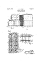
I An illustrative embodiment of'this invention is shown in the accompanying drawings, in which j r r v Fig. l" is a side elevation of a wall or partition embodying the novel structural features 1931. Serial No. 530,011.
provided by this invention; Fig. 2- is a vertical transverse section, taken on line 2-2 in" Fig. 1, and drawn on an enlarged scale; and Fig. 3 is a top edge view of a single building unit according to this invention. a v 1 Similar characters of reference are employed in the above described views, to indi cate corresponding parts.
In the construction and erection of a wall, either in the form of all-external wall or an interior partition, building units are first fabricated to be taken to the job for erection. Each such building unit comprises a'pair of side panels. 5, preferably made of stiff comparatively heavy pressed paper or fiberboard, usually approximating from one quarter to three-eighths of an inch in thickness. I have found it feasible to use panels having dimen-' sions of approximately four by three feet, al-
though larger or smaller dimensions may be employed. Said panels are arranged side by side in spaced apart relation, according to the thickness of the ultimate wall or partition desired to be erected. Said panels are tied together by transverse tie-rods 6, which e'xtend entirely through the same, and which are relatively spaced apart at suitable intervals. Said tie-rods 6 are preferably made of round iron of about one-quarter inch diameter, and are provided at their respective end portions with screw-threads. Threaded onthe respective end portions of the rods are inner backing nuts 7, which provide stop abutments to engage the inner sides of the panels 5, so as to position the latter in desired spaced apart relation. The panels are perforated to receive thetie-rod end portions, whereby the latter may project outwardly beyond the outer faces of the panels. Threaded. on the tie-rods are fastening nuts 8 which are screwed home on the tie-rod ends so as to engage the outer faces; of the panels 5, whereby the latter are firmly fixed in stopped relation against said inner backingnuts 7, and thus assembled securely together in de-. sired spaced relation. Adjustably threaded on the exteriorly projecting ends of said tierods are p irs of jamb-nuts 9, which'may be adjusted and locked on the tie-rods in'outwardly oif-set relation to the outer faces of faces of the panels 5. In mounting the metal lath sections 10, the extremities of the tie-rods pass through the mesh thereof, thereby holding the*lathagainst displacement in directions of the face planes thereof. To secure the metal lath against displacement from operative supported relation to the tie rod-extremities, fastening nuts 9 are screwed upon the latter to abut the outer faces of the assembled lath sections.
In one embodiment of my invention, the metal lath sectionspare applied when fabricatingjthebuilding units, in which case it is preferable to inturn-the marginal ,edgesof thelath sections 10 as indicated at 10 in: Fig. 3. If desired,rhowever, the metal lath may be omitted from the fabricated building units, and may be subsequently applied thereto after said units are assembled inerectin-g awall, thus permitting. the use of areas of metal lath greater than theface areas of the individual building units.
The building units are providedwith means to mutually interlock the same togetherwhen a,lplura lity of the same are assembled edge towedge during the course of erecting a wall. The interlocking means comprises female sheet metal;bindin-gelementsll having a longitudinal open receiving channel or groove 11, and male metal sheet building elements IQ'h-aving .a longitudinal-tongue or rib 12. Said female sheet metal binding elements are-fastenecbby-rivets, or any other suitable form of fastening means, to and along the bottom andrear vertical edges of: the respective panels 5, while said male sheet metal bindingelements are fastened by-rivets, or other suitable fastening means, to and along thetopand forward vertical edges of the respective panels. 5.
In the use of the above describedbuilding units,preparatory to erection ofa wall there- With, a;suitable:foun'dation, as 13 (see Figs. 1,and2) is prepared upon which the lower course ofassembled units may be supported. TheL-firstfor lower course of building-units is :mounted on the foundation 13, with the forward and rearvertical edges of the panels 5-. of adjoining unitsinterlocked together by the-insertion 10fthe tongue or rib 12 ofa ma-lesheet metalbinding element 12 of-the one-into-the channel'or-groove 11 of a femalesheetmetal binding element 11 of the other. .By thus interlocking the building units together, thesa-me are held at their verticalsides, rigid and'secure against lateral displacementzrelative onev to the other. The next course of building units is now mounted upon the first course,;preferably in .the staggeredrelation illustrated in Fig. :1 of the drawings. The-second course is rigidly interlocked with the first course by the in sertion of the tongues or ribs 12 of the male sheet metal binding elements 12 at the top edges of the panels of units forming said first course into the channels or grooves 11 of the female sheet metal binding elements 11 at the bottom edges of the panels of units formingjsaid second course, thus interlocking the meeting ed es of the respective courses together, whereby the same are held rigid and secure against. relative displacement at the same time the vertical meeting edges of units forming said second course'are interlocked by the male and female elements at their adj oining 'vertical edges, in the same manner as already described with respect to the units of the first course. continued until a. desired height andlength of wall is, produced. 1
After the erection of-the buildingcunitsin the manner above described, orfrom timetc time as given desired sections thereof me These operations may "be assembled, a wet mixture of concrete is poured into the space between the-spaced apart'panels .5, thus. forming a strong. and
durable concrete vwall core 14. Such wall core will not only be moldedby; theform pro-L vided by the erected building units, :but will also be reenforced by the vtransverse tie-rods 6 against cracking. building. units. remain in place,.,they. serve to shield the concrete core wall, and aid 'in guardingthe same against dis-integration.
After the wall has been: erected, either. to
include the preassemble'd metal lath sections, or to include metal. lath fa-cings applied. during or after completion of. thewall, vthesame is ready to. receive the application of stucco or plaster coatings. If the Wallis: an external wall, a suitably mixed cement stuccov coating; I
15 is applied to. the metal. lath retaining base 10, and since the latter is off-set from the outer face of the-wall, said stucco coating will be likewise spaced therefrom so as'to forman intermediate air space 16 contiguous-and parallel to the outer face of the wall. Such air space 16 provides. a very efficient: heat insulation effectand also assures. a moisture proof and dry inner wall condition.
In like. manner a suitable interior, plaster Since the, panels .5 of the assembled building units and interior concrete core wall.
It will be further understood that the novel wall structure provides a construction of low cost as well as one which may be rapidly erected with a minimum of skilled labor; at the same time a very strong and durable wall is provided, and one having highly efficient moisture and heat insulation.
As many changes could be made in the novel wall structure as a Whole, and in the novel pre -fabricated building units entering into the construction of the same, and many apparently widely different embodiments of the features of this invention could be made without departing from the scope thereof as defined by the appended claims, it is intended that all matter contained in the above description or shown in the accompanying drawings shall be interpreted as illustrative and not in a limiting sense.
I claim 1. A building wall comprising a plurality of interjoined abutting building units; each unit including a pair of laterally spaced panels and transverse tie-rods for securing said panels in unit forming relation; the meeting edges of panels of adjoining units having cooperative elements for interlocking said units together in wall forming relation; and a cast concrete core wall filling the space provided between the panels of said units.
2. A building wall comprising a plurality of interioined abutting building units;each unit including a pair of laterally spaced panels and transverse tie-rods for securing said panels in unit forming relation, said tie-rods having threaded end portions extending through said panels, nuts threaded on said tie-rods on opposite sides of said panels to hold the latter in fixed spaced relation; the meeting edges of panels of adjoining units having cooperative elements for interlocking said units together in wall forming relation; and a cast concrete core wall filling the space provided between the pane s of said units.
A building wall comprising a plurality of interjoined abutting building units; each unit including a pair of laterally spaced panels and transverse tie-rods for securing said panels in unit forming relation, said tie-rods having threaded end portions extending through said panels, nuts threaded on said tie-rods on oppositesides of said panels to hold the latter in fixed spaced relation; the meeting edges of panels of adjoining units having cooperative elements for interlocking said units together in wall forming relation; and a cast concrete core wall filling the space provided between the panels of said units, jamb-nuts on eXteriorly projecting end portions of said tie-rods, metal lath material engaged on said exterior tie-rod end portions and stopped by said jamb-nuts in outwardly spaced relation to building unit panels, keeper nuts to secure said metal lath thus assembled, and a plastic coating enveloping said metal lath and so supported thereby as to provide insulating air space contiguous and parallel to the wall.
4. A building wall comprising a plurality of interjoin'ed abutting building units; each unit including a pair of paperboard panels and transverse metallic tie-rods extending therethrough having means thereon to engage and hold said panels in predetermined paral lel spaced relation, male sheet metal binding elements on certain of the marginal edges of said panels and female sheet metal binding elements on other of the marginal edges of said panels; the meeting edges of panels of adjoining units being interconnected. by
cooperation of said male and female binding elements; anda cast concrete core wall filling the space provided between the panels of said units. V o
5. "A building wall comprising a plurality of interjoined abutting building units; each unit'including a pair of paperboard panels and transverse metallic tie-rods extending therethrough having means thereon to engage and hold said panels in predetermined parallel spaced relation, male sheet metal bind ing elements on certain of the marginal edges of said panels'and'feinale sheetmetal binding elements on other of the marginal edges "of said panels; the meeting edges of panels of adjoining units being interconnected .by cooperation of said male and female binding elements; metal lath material engaged'on exteriorly projecting end portions of said tierods, means to retain said metal lath so'engaged; and aplastic coating enveloping said metal lath and so supported thereby so as to provide insulating air space contiguous and parallelto thewall.
6. A wall building unit, comprising a pair of laterally spaced panels and transverse metallic tie-rodse-Xtending therethrough hav-' ing means thereon to engage and hold said. panels in predetermined parallel spaced rela tion, and certain of said marginal edge por tions of said panels'having femalesheet metal binding elements secured thereto and other of said marginal edge portions of said panels" having male sheet metal binding elements Bil secured thereto, said elements being adapted to cooperate in interjoining abutting units together. I Y
7. A wall building unit, comprising a pair of &laterally spaced panels and transverse metallic tie-rods extending therethrough having means thereon to engage and hold said panels in predetermined parallel spaced relation, certain of said marginal edge portions of said panels having female sheet metal binding elements secured thereto and other of said marginal edge portions of said panels having male sheet metal binding elements secured thereto said elements being adapted toicooperate in: interj oining'abutting units tog etli'er,i'metal lathimateri-al engaged on eX- te'riorly projecting end portions of' said" tierods,'and means torretain said latch material so engaged and spaced outwardly from the exteriorcface: of: an adjacent panel.
8, Axwall building unit comprising a pair of; paperboard panels, metallic tie-rods having threadedend portions extending transversely through and between said panels, nuts threaded ion said'tie-rods on opposite sides ofesaidipanels to hold the latter in predetermined spaced-parallel relation, and elements connected with the marginal edge portions of said-;panels adapted to interjoin abutting I units :whenassemble'd. edge: to edge.
' 9.-JA wall building'nnit'comprising a pair of paperboard panels,:metallic' tie-rods havingfithread-edqend portions 'extendingitransversely through and between said panels,
nuts threaded on said tie-rods onopposite I sides of said panels to hold the latter in predeterminedspaced parallelrelation, and cer-' tain of said'marginal edge portions of. said panels having female sheet metal binding elements. secured thereto and other of said mar ginal edge portions of" said-panels having male sheet metal binding elements secured thereto, said elements beingadapted to cooperate in'interjoining abutting units':t0- gether.
10. A wall'ibuilding unit comprising a pair of paperboard panels, metallic tie-rods hav ing threaded end" portions 'extendingtrans versely through and between said panels, nuts' threaded on said tie rodson opposite sidesxof said-panels to hold the latter 'in.predeter-" mined spaced parallel relati0n,'certai 'n of said marginal edge portions of said panels having female sheet metal binding elements secured thereto and other of said marginal edge portions of'said panels having male sheet metal binding elements secured thereto, said elements being adapted to cooperate ininter-' joining abutting units together, adjustable jamb nuts on exteriorly projecting end porti'ons of said tie-rods, metallath material. engaged on-said exterior tie-rod end portions and stopped in outwardly spaced: relation to the exterior face of an adjacent panel, and keeper'nuts to secure said lath'material'thus assembled.
In testimonyythat :I claim-the invention set forth above I have hereunto set my hand this 11th day of April, 1931;
RUSSELL C. GRAEF.
Priority Applications (1)
| Application Number | Priority Date | Filing Date | Title |
|---|---|---|---|
| US530011A US1852049A (en) | 1931-04-14 | 1931-04-14 | Building construction |
Applications Claiming Priority (1)
| Application Number | Priority Date | Filing Date | Title |
|---|---|---|---|
| US530011A US1852049A (en) | 1931-04-14 | 1931-04-14 | Building construction |
Publications (1)
| Publication Number | Publication Date |
|---|---|
| US1852049A true US1852049A (en) | 1932-04-05 |
Family
ID=24112094
Family Applications (1)
| Application Number | Title | Priority Date | Filing Date |
|---|---|---|---|
| US530011A Expired - Lifetime US1852049A (en) | 1931-04-14 | 1931-04-14 | Building construction |
Country Status (1)
| Country | Link |
|---|---|
| US (1) | US1852049A (en) |
Cited By (8)
| Publication number | Priority date | Publication date | Assignee | Title |
|---|---|---|---|---|
| US2642645A (en) * | 1948-09-13 | 1953-06-23 | Charles A Commet | Form for concrete constructions |
| US2795949A (en) * | 1950-06-14 | 1957-06-18 | Muhr John | Wall structure of panels and posts |
| FR2322988A1 (en) * | 1975-09-02 | 1977-04-01 | Leroy Victor | MODULAR PANEL FORMWORK ESPECIALLY FOR CONCRETE CONSTRUCTION |
| US6405505B1 (en) * | 2000-06-02 | 2002-06-18 | Carlo Alberti | Modular interlock wall form |
| US20130333316A1 (en) * | 2012-06-19 | 2013-12-19 | Jesse Westaby | Form System With Lath Covering |
| US8950137B2 (en) * | 2010-04-02 | 2015-02-10 | Romeo Ilarian Ciuperca | Composite insulated foam panel |
| US20160281361A1 (en) * | 2013-12-17 | 2016-09-29 | Benjamin Baader | Insulated concrete panel form and method of making same |
| US20190195255A1 (en) * | 2010-09-24 | 2019-06-27 | Hiroshi Shimizu | Accessory attachment structure for steel plate-reinforced concrete structure, design system and design method of steel plate-reinforced concrete structure, consruction method of steel plate-reinforced concrete structure, and steel plate-reinforced concrete structure |
-
1931
- 1931-04-14 US US530011A patent/US1852049A/en not_active Expired - Lifetime
Cited By (11)
| Publication number | Priority date | Publication date | Assignee | Title |
|---|---|---|---|---|
| US2642645A (en) * | 1948-09-13 | 1953-06-23 | Charles A Commet | Form for concrete constructions |
| US2795949A (en) * | 1950-06-14 | 1957-06-18 | Muhr John | Wall structure of panels and posts |
| FR2322988A1 (en) * | 1975-09-02 | 1977-04-01 | Leroy Victor | MODULAR PANEL FORMWORK ESPECIALLY FOR CONCRETE CONSTRUCTION |
| US6405505B1 (en) * | 2000-06-02 | 2002-06-18 | Carlo Alberti | Modular interlock wall form |
| US8950137B2 (en) * | 2010-04-02 | 2015-02-10 | Romeo Ilarian Ciuperca | Composite insulated foam panel |
| US20190195255A1 (en) * | 2010-09-24 | 2019-06-27 | Hiroshi Shimizu | Accessory attachment structure for steel plate-reinforced concrete structure, design system and design method of steel plate-reinforced concrete structure, consruction method of steel plate-reinforced concrete structure, and steel plate-reinforced concrete structure |
| US20130333316A1 (en) * | 2012-06-19 | 2013-12-19 | Jesse Westaby | Form System With Lath Covering |
| US8752349B2 (en) * | 2012-06-19 | 2014-06-17 | Jesse Westaby | Form system with lath covering |
| US20160281361A1 (en) * | 2013-12-17 | 2016-09-29 | Benjamin Baader | Insulated concrete panel form and method of making same |
| US10006200B2 (en) * | 2013-12-17 | 2018-06-26 | Benjamin Baader | Insulated concrete panel form and method of making same |
| US20190093355A1 (en) * | 2013-12-17 | 2019-03-28 | Benjamin Baader | Insulated concrete panel form and method of making same |
Similar Documents
| Publication | Publication Date | Title |
|---|---|---|
| US2316819A (en) | Wall structure | |
| US1990656A (en) | Self-sustaining partition | |
| US2063309A (en) | Building wall construction unit | |
| US1877898A (en) | Building construction | |
| US1852049A (en) | Building construction | |
| US1640065A (en) | Interior wall | |
| US2064704A (en) | Arch construction | |
| US1965601A (en) | Securing member for building construction units | |
| US2309147A (en) | Building construction | |
| US1775234A (en) | Concrete building construction | |
| US2652713A (en) | Structural section | |
| US2075773A (en) | Building construction | |
| US1951421A (en) | Wall structure | |
| US2169255A (en) | Building unit and element | |
| US2153913A (en) | Building block | |
| US1374356A (en) | Reinforced concrete construction | |
| US520137A (en) | Fireproof building-wall | |
| US2145496A (en) | Building construction | |
| US2476135A (en) | Furred concrete building wall | |
| US1305492A (en) | Waxl construction | |
| US1627171A (en) | Form for building construction | |
| US1892498A (en) | Building construction | |
| US1711026A (en) | Brick veneer and system | |
| US1501986A (en) | Building construction | |
| US1619300A (en) | Wall construction |