US185189A - Improvement in invalid-chairs - Google Patents
Improvement in invalid-chairs Download PDFInfo
- Publication number
- US185189A US185189A US185189DA US185189A US 185189 A US185189 A US 185189A US 185189D A US185189D A US 185189DA US 185189 A US185189 A US 185189A
- Authority
- US
- United States
- Prior art keywords
- seat
- invalid
- chairs
- support
- bars
- Prior art date
- Legal status (The legal status is an assumption and is not a legal conclusion. Google has not performed a legal analysis and makes no representation as to the accuracy of the status listed.)
- Expired - Lifetime
Links
- 241000139306 Platt Species 0.000 description 4
- 210000003414 Extremities Anatomy 0.000 description 2
- 238000010276 construction Methods 0.000 description 2
- 238000006073 displacement reaction Methods 0.000 description 2
- 230000000717 retained Effects 0.000 description 2
Images
Classifications
-
- B—PERFORMING OPERATIONS; TRANSPORTING
- B60—VEHICLES IN GENERAL
- B60N—SEATS SPECIALLY ADAPTED FOR VEHICLES; VEHICLE PASSENGER ACCOMMODATION NOT OTHERWISE PROVIDED FOR
- B60N2/00—Seats specially adapted for vehicles; Arrangement or mounting of seats in vehicles
- B60N2/02—Seats specially adapted for vehicles; Arrangement or mounting of seats in vehicles the seat or part thereof being movable, e.g. adjustable
- B60N2/22—Seats specially adapted for vehicles; Arrangement or mounting of seats in vehicles the seat or part thereof being movable, e.g. adjustable the back-rest being adjustable
- B60N2/225—Seats specially adapted for vehicles; Arrangement or mounting of seats in vehicles the seat or part thereof being movable, e.g. adjustable the back-rest being adjustable by cycloidal or planetary mechanisms
- B60N2/2252—Seats specially adapted for vehicles; Arrangement or mounting of seats in vehicles the seat or part thereof being movable, e.g. adjustable the back-rest being adjustable by cycloidal or planetary mechanisms in which the central axis of the gearing lies inside the periphery of an orbital gear, e.g. one gear without sun gear
Definitions
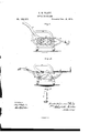
- ⁇ Figure l of the drawing is arepresentation of a side elevation of my invention.
- Fig. 2 is a longitudinal central section of the same.
- Fig. 3 is a detached plan view of the springinvention consists in the manner otcombining
- A represents the seat ofthe chair, supported upon legs B, in the form of the periphery of a half-ellipse.
- the seat A has upon each side suitable arms a. Pivoted to the rear end -of the seat A, or to the lower portion of the arms a, is a back, C, which is capable of any angle of adjustment to the seat, from a right angle to a horizontal plane, constituting with the-seat a continuous bed-surface, by a hand-wheel, D, the same having upon its inner face a toothed wheel, b, meshing with the teeth upon a gear-wheel, c, which is rigidly connected to one end of a horizontal rod, d, said rod having keyed thereto gear-wheels c, the teeth of which mesh with the'teeth upon rack-bars E, sliding within xed guide-plates f, the upper ends of said bars E being connected to the back C, and braced by plates g.
- the guide-plates f serve to prevent the bars from being pressed out laterally by any strain coming thereon, and the displacement of the same; and it will be noticed that the bars E, in place of being rigidly connected to the back G, are pivoted, which allows them to yield when anyA strain is brought thereon, and thereby prevent them from binding and becoming injured.
- the rack-bars are necessarily longer than those used upon the leg-support, they require a brace to give additional security against any lateral strain upon them, by pivoting thereto and to the back ot' the chair the plates g, before referred to.
- Hinged to the front edge of the fixed seat A is a leg-support, F, capable of any angle of inclination from a horizontal plane with the seat and back to a right angle with the seat, bya mechanism the same as that employed to operate the back C, consisting of the hand-wheel D', toothed wheels b, gear-wheel c', rod al', wheels e', guideplates j", pawl h', and rack-bars E.
- a footrest, Gr is secured to the leg-support F by an extension piece, t', connected thereto, and which is capable ot"sliding within a recess formed in the support, and is'held in the position placed by a spring-catch, j, en raging with the teeth upon a ratchet bar or plate, k, secured to, or formed upon, the edge ot' the extension-piece i.
- the leg-support F may be adapted to any greater length of limbs than is provided for in the length ofthe leg-support itself..
- the hinged leg-support F having the spring-catch 7',in combination with the sliding piece t', carrying ratchet bar or plate 7c, and
- hinged foot-rest G substantially as and for the purpose set forth.
- a reeliningohair consisting of the seat A, having the adjustable back U, leg-support F, foot-rest G, extension-piece z', serrated bar
Landscapes
- Engineering & Computer Science (AREA)
- Aviation & Aerospace Engineering (AREA)
- Transportation (AREA)
- Mechanical Engineering (AREA)
- Chairs For Special Purposes, Such As Reclining Chairs (AREA)
Description
syn. PLATT.
-. .INVALID CHAIR.
No. 185,189. Patented Decv.12,1`878.
WITNESSES 'n wwwa Juf, @MEM 1;' SmZ/JQZTNJW@ THE GRAPHIC JL-Y.
SMITH -HARRISON PLATT, OFVBROOKL'Y'N, NEW SYORK.
4INIFFRO-VENI ENT IN INVALID-CHAIRS.
Specification forming part-of vLettere PatentNo. 15825,?1 S9, dated Decemberl' 1876; application'ii-led August 9, 1876.
To all whom it may concern Beitknown thatLSMI'rHHARRsoN PLATT,
of Brooklyn,in the county of Kings and State of New York, have invented a new and valu` able Improvement in Invalid and Comfort Chairs; andldo hereby declare thatthefollowing is a full, clear, and exact description of the construction and operation of the same, reference being had to the annexed drawings, making a part of this specification, and to the letters and figures of reference marked thereon.
`Figure l of the drawing is arepresentation of a side elevation of my invention. Fig. 2 is a longitudinal central section of the same.
' Fig. 3 is a detached plan view of the springinvention consists in the manner otcombining,
arranging, and constructing the severalparts, whereby these results are accomplished, as hereinafter described, and subsequently pointed out in the claims.
In the accompanying drawings, A represents the seat ofthe chair, supported upon legs B, in the form of the periphery of a half-ellipse. The seat A has upon each side suitable arms a. Pivoted to the rear end -of the seat A, or to the lower portion of the arms a, is a back, C, which is capable of any angle of adjustment to the seat, from a right angle to a horizontal plane, constituting with the-seat a continuous bed-surface, by a hand-wheel, D, the same having upon its inner face a toothed wheel, b, meshing with the teeth upon a gear-wheel, c, which is rigidly connected to one end of a horizontal rod, d, said rod having keyed thereto gear-wheels c, the teeth of which mesh with the'teeth upon rack-bars E, sliding within xed guide-plates f, the upper ends of said bars E being connected to the back C, and braced by plates g. The guide-plates f serve to prevent the bars from being pressed out laterally by any strain coming thereon, and the displacement of the same; and it will be noticed that the bars E, in place of being rigidly connected to the back G, are pivoted, which allows them to yield when anyA strain is brought thereon, and thereby prevent them from binding and becoming injured. As there is always greater strain upon the back of the chair than on the leg-support, and as the rack-bars are necessarily longer than those used upon the leg-support, they require a brace to give additional security against any lateral strain upon them, by pivoting thereto and to the back ot' the chair the plates g, before referred to. At the free ends of the bars E are stops l, to prevent them from passing beyond the teeth of the wheels e when the back C assumes a vertical position. rEhe hand-wheel D is retained in any desired position by a loose pawl, h, so that all possible changes ot' the angle ot' inclination of the back C to the fixed seat A` may be made by the occupant of the chair, while either sitting or reclining therein, by simply turning the hand-wheel D. Hinged to the front edge of the fixed seat A is a leg-support, F, capable of any angle of inclination from a horizontal plane with the seat and back to a right angle with the seat, bya mechanism the same as that employed to operate the back C, consisting of the hand-wheel D', toothed wheels b, gear-wheel c', rod al', wheels e', guideplates j", pawl h', and rack-bars E. A footrest, Gr, is secured to the leg-support F by an extension piece, t', connected thereto, and which is capable ot"sliding within a recess formed in the support, and is'held in the position placed by a spring-catch, j, en raging with the teeth upon a ratchet bar or plate, k, secured to, or formed upon, the edge ot' the extension-piece i. By this arrangement the leg-support F may be adapted to any greater length of limbs than is provided for in the length ofthe leg-support itself..
Having now fully described my invention,
what I claim as new, and desire to secure by Letters Patent, is-
l. The hinged leg-support F, having the spring-catch 7',in combination with the sliding piece t', carrying ratchet bar or plate 7c, and
hinged foot-rest G, substantially as and for the purpose set forth.
2. In a reclining-chair, the combination with.
the back C, pivoted to the seat-A, and carrying the pivoted rack-bars E, provided with stops Zand lpivoted brace-plates-g, of guideplates f, hand-Wheel D, and gear-Wheels b ce, substantially as and for the purpose set forth.
3. A reeliningohair consisting of the seat A, having the adjustable back U, leg-support F, foot-rest G, extension-piece z', serrated bar
Publications (1)
| Publication Number | Publication Date |
|---|---|
| US185189A true US185189A (en) | 1876-12-12 |
Family
ID=2254594
Family Applications (1)
| Application Number | Title | Priority Date | Filing Date |
|---|---|---|---|
| US185189D Expired - Lifetime US185189A (en) | Improvement in invalid-chairs |
Country Status (1)
| Country | Link |
|---|---|
| US (1) | US185189A (en) |
Cited By (5)
| Publication number | Priority date | Publication date | Assignee | Title |
|---|---|---|---|---|
| US3036830A (en) * | 1959-10-16 | 1962-05-29 | Leon G Hotas | Spinal exercise devices |
| US3282605A (en) * | 1965-01-08 | 1966-11-01 | Russell E Nihlean | Runabout wheelchair |
| US4775184A (en) * | 1986-11-26 | 1988-10-04 | Larkin Lloyd V | Rocking chair |
| US6193316B1 (en) * | 1998-12-24 | 2001-02-27 | Daimlerchrysler Ag | Vehicle seat with backrest part adjustment |
| US20080157501A1 (en) * | 2004-10-29 | 2008-07-03 | Flemming Moller | Comfort Wheelchair |
-
0
- US US185189D patent/US185189A/en not_active Expired - Lifetime
Cited By (6)
| Publication number | Priority date | Publication date | Assignee | Title |
|---|---|---|---|---|
| US3036830A (en) * | 1959-10-16 | 1962-05-29 | Leon G Hotas | Spinal exercise devices |
| US3282605A (en) * | 1965-01-08 | 1966-11-01 | Russell E Nihlean | Runabout wheelchair |
| US4775184A (en) * | 1986-11-26 | 1988-10-04 | Larkin Lloyd V | Rocking chair |
| US6193316B1 (en) * | 1998-12-24 | 2001-02-27 | Daimlerchrysler Ag | Vehicle seat with backrest part adjustment |
| US20080157501A1 (en) * | 2004-10-29 | 2008-07-03 | Flemming Moller | Comfort Wheelchair |
| US8186695B2 (en) * | 2004-10-29 | 2012-05-29 | R82 A/S | Comfort wheelchair |
Similar Documents
| Publication | Publication Date | Title |
|---|---|---|
| US185189A (en) | Improvement in invalid-chairs | |
| US403318A (en) | Reclining-chair | |
| US336387A (en) | Adjustable chair | |
| US327775A (en) | dodge | |
| US637706A (en) | Combined rocking-chair and lounge. | |
| US54869A (en) | Improved chair | |
| US238896A (en) | Thomas habdmg | |
| US271596A (en) | browne | |
| US242573A (en) | Geoege wilson | |
| US300228A (en) | Convertible chair | |
| US155452A (en) | Improvement in opera-chairs | |
| US1024966A (en) | Operating-table. | |
| US206379A (en) | Improvement in invalid-chairs | |
| US364732A (en) | Ellis m | |
| US326368A (en) | Chair | |
| US155366A (en) | Improvement in reclining-chairs | |
| US213894A (en) | Improvement in reclining-chairs | |
| US786308A (en) | Adjustable and reclining chair. | |
| US184438A (en) | Improvement in reclining-chairs | |
| US154873A (en) | Improvement in reclining-chairs | |
| US229286A (en) | towers | |
| US373296A (en) | Convertible chair | |
| US318795A (en) | Recltning-chair | |
| US1108897A (en) | Reclining-chair. | |
| US275368A (en) | Apparatus for the treatment of uterine displacement and hernia |