US1851482A - Automatic or semiautomatic telephone system - Google Patents
Automatic or semiautomatic telephone system Download PDFInfo
- Publication number
- US1851482A US1851482A US424886A US42488630A US1851482A US 1851482 A US1851482 A US 1851482A US 424886 A US424886 A US 424886A US 42488630 A US42488630 A US 42488630A US 1851482 A US1851482 A US 1851482A
- Authority
- US
- United States
- Prior art keywords
- path
- bye
- circuit
- relay
- selector
- Prior art date
- Legal status (The legal status is an assumption and is not a legal conclusion. Google has not performed a legal analysis and makes no representation as to the accuracy of the status listed.)
- Expired - Lifetime
Links
- 238000012360 testing method Methods 0.000 description 53
- 238000004804 winding Methods 0.000 description 33
- 230000004044 response Effects 0.000 description 8
- 241000068451 Enterosora Species 0.000 description 2
- 230000001939 inductive effect Effects 0.000 description 2
- 241000272470 Circus Species 0.000 description 1
- 102000018361 Contactin Human genes 0.000 description 1
- 108060003955 Contactin Proteins 0.000 description 1
- 230000009471 action Effects 0.000 description 1
- 230000004075 alteration Effects 0.000 description 1
- 230000015572 biosynthetic process Effects 0.000 description 1
- 230000000295 complement effect Effects 0.000 description 1
- 230000007547 defect Effects 0.000 description 1
- 230000000977 initiatory effect Effects 0.000 description 1
- 239000003550 marker Substances 0.000 description 1
- 238000000034 method Methods 0.000 description 1
- 230000008569 process Effects 0.000 description 1
- NQLVQOSNDJXLKG-UHFFFAOYSA-N prosulfocarb Chemical compound CCCN(CCC)C(=O)SCC1=CC=CC=C1 NQLVQOSNDJXLKG-UHFFFAOYSA-N 0.000 description 1
Images


Classifications
-
- H—ELECTRICITY
- H04—ELECTRIC COMMUNICATION TECHNIQUE
- H04Q—SELECTING
- H04Q3/00—Selecting arrangements
Description
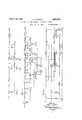
March 29, 1932. J. H. E. BAKER AUTOMATIC OR SEMIAUTOMATIC TELEPHONE SYSTEM Filed Jan. 31, 1950 8 Sheets-Sheet 1 wk K3 INVENTOR JOHN H. E. BAKER ATTORNEY J. H. E. BAKER 1,851,482
AUTOMATIC OR SEMIAUTOMATIG TELEPHONE SYSTEM Filed Jan. 31, 1950 8 Sheets-Sheet 2 0 0K 507- QUE INVENTOR JOHN H.151. BAKER Q 0; 1 u NE m w Nh 7 Rh v QM x Elli? )fl QIVAI:
. m mv kxfi h Q 3 N w Dw x Q x NE N25 w J Y v NM x N\ 7 A a 3 l M Q \N x x March 29, 1932.
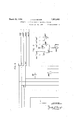
1930 8 Sheets-Sheet 3 BAKER b C E 25 i 2 ATTO March 29, 1932. J. H. E. BAKER AUTOMATIC OR SEMIAUTOMATIC TELEPHONE SYSTEM Filed Jan. 31,
. w E a 1 m E @J .8 m Ni 1; X vw Mn v5 hwx W MN v 38 N? \m \R \E *MQ TQ k March 29, 1932. J BAKER 1,851,482
AUTOMATIC OR SEMIAUTOMATIC TELEPHONE SYSTEM FIG. 6
hi2 I March 29, 1932. J. H E. BAKER AUTOMATIC 0R SEMIAUTOMATIC TELEPHONE SYSTEM Filed Jan. 31, 1950 8 Sheets-Sheet OR E. BAKER flak ATTORNE INVENT JOHN H.
9111i MS m m March 29, 1932. J. H. E BAKER 1,851,432
AUTOMATIC OR SEMIAUTOMATIC' TELEPHONE SYSTEM Filed Jan. 31, 1930 8 Sheets-Sheet 6 INVENTOR JOHN H.E. BAKER W 14 ATTORNEW March 29, 1932. J. H. E. BAKER AUTOMATIC OR SEMIAUTOMATIC TELEPHON E SYSTEM Filed Jan. 31, 1930 8 Sheets-Sheet 7 mom INVENTOR JOHN H. E. BAKER NEY 8 Sheets-Sheet 8 J H. E. BAKER Filed Jan. 31, 1930 AUTOMATIC OR SEMIAUTOMATIC TELEPHONE SYSTEM March 29, 1932.
INVENTOR JOHN H.E. BAKER BY 1 I 7 "q ATTORNEY Fatented Mar. as, 1932 unites.
JOHN HENRY ELVIDGE BAKER, or ALnwYci-I, Lonnon; ENGLAND, AssIeNoR TO IN- TERNATIONAL STANDARD ELECTRIC CORPORATION, or new YORK, N. Y.
AUTOMATIC 01% SEMIAUTOMATIC TELEPHONE SYSTEM This invention relates to automatic and semi-automatic telephone exchange systems and has particular reference to systems of the kind in which bye-path circuits are employed for controlling the operation of the conversation switches thereat.
It has been the practice in such systems in the past to make a search from one switching stage for an idle conversation switch in I the dialled impulses while the main bye-path switch is advancing towards the wanted group of outlets. It has also been proposed" to )IOVlClG the main switches with a plurality of sets of wipers and bank contact sets andto make the switch conduct a simultaneous hunt over such wiper sets. It is the object of the present invention to provide means whereby this disadvantage is still further overcome and whereby at the so same time economy of apparatus is obtained. In the previous arrangements also it has been necessary to associate a plurality of conversational switches witha single bye-path circuit with the result that when a bye-path circuit and one of its associated conversational switches was in use, the remainder of the associated conversational switches were artificially busied.
It is a further object of the present invention to obviate this disadvantage also. According to one feature of the present invention, in extending a connection'from one selecting stage to another, search is made for an idle bye-path circuit only. Since the number of bye-path circuits is less than the number of conversational switches, this arrangement reduces the number of outlets over which the bye-path switch is required to search between successivedigits. Thus it becomes possible to provide arrangements Application filed January 31, 1930, Serial No. $34,886," and in. Great Britain February 14, 1929.
whereby the wipers "advance ,:over entire groups of outlets between successive impulses.
ens hunting in a pluralitylof levels and lwipl er-switching, I
According toanother feature ofthe inven tion, therefore, digital impulses are received directly by the bye-path switch of a, selector stage. I r
In such an arrangement the bye-path circuit will be adapted to make connection to an idle conversational switch leading in the wanted direction and associated with the byepath circuit' It is possible, therefore, to pro-' vide a very flexible arrangement of conversational and bye-path circuits in'a selector stage, and according to a further feature of the invention each conversational switch in a selector stageis associated with the pin: rality of bye-path circuits. i With such an arrangement also, provision must be made for avoiding a cross between two connections which are being set up simultaneously. This defect may occur when a bye-path circuit having been seized froma preceding bye-path circuit searches for 'an idle conversational switch and then causesv initiation of a connection between the last; mentioned conversational switch and the predetermined preceding conversational switch. This danger may be taken care of, for example, by providing at each switching stage a suitable device'which determines that a" true connection has been made. Thus a single common testing circuit may be associated in common with all the byepath circuits of a group in a selector stage. With such an arrangement, whena connection has ostensibly been set up from thesaid selector stage to the next stage, the test circuit is taken into use and a test is made'ofthe formation of a loop through the two stages. Since only I one testing circuit is provided, only one conarrangements described. Thus, each byepath in a group of bye-paths at one selector stage may be made accessible from a plurality of groups of bye-paths in the preceding a plurality of digital values; in this case the said group of bye-paths must be associated with apl'urality of groups of conversation switches which have vaccessto trunks leading in a plurality of directions and which areaccessible from one or more groups of conversational switches-in thepreceding stage.
It will be appreciated that the groups or byepath circuits may vary in number. If, however, the banks of a bye-pathswitch were divided up exactly in accordance with the size of the groups of succeeding bye-paths to which it had access, alterations in the size in the groups due to changes in traflic distribus tionwould bedifficult. In order to obviate this equal number of outlets maybe provided for each group of bye-paths su liicient to provide for themaximum trafiic possible. A number of outlets in each of some or allot the groups of outlets could then be permanently busied so as to provide groups of the required sizes. Further features of the invention will be apparent from the following description of certain embodiments of the invention and are set out in the appended statement of claims. v
The bye-path circuits may comprise common control means for controlling the peration'of the conversation switches.
The layout of three typical systems embodying the features of the invention are il- I lustrated in Figs. 1, 2 and 3.
/ A'short description of Figures 4-12 will now be given:
Figure 4: shows a first path circuit and indicates the first and second line finders together with a subscribers line and starting circuits.
Figure 5 shows a first bye-path circuitineluding a hunting switch RMl which serves to connect the bye-path to its associated paths and. a switch RM2 of the selector type, the
- functions of which'wil-l be described later.
' Figure 6 shows an intermediate path switch.
Figure 7 showsan intermediate bye-path which is similar to the first bye-path described above. V
Figure 8 shows a final path circuit.
Figure 9 shows a final bye-path.
Figure 10 showsatest circuit, one of which is associated with all the bye-path circuits of the first stage and of the second stage.
Figure 11 shows diagrammatically a particular embodiment of the arrangement shown in Figure 5.
Referring first to Figure 1 of the accomanying drawin s, a calling subscribers line LC signals all idle first bye-path ciruits C1 of the group associated with the sub- .c iberso that their RMl switches hunt for free first group finder such as S1. When 1 is found line finders LF2, LFl operate in urn to make connection to the calling line. A bye-path switch RM2 individual to the control circuit Cl responds to the first series of impulses and on the cessation thereof hunts for an. idle bye-path circuit C2 associated with second group finders such asS2.in the vegan:
, required group at the next switch stage, and
subsequently the bye-path switch? RMQ individual to the control circuit C2 responds to the second digit received over the bye-path.
circuit Cl and selects an idle bye-path circuit associated final finder switches S3 giving access to the group of subscribers lines to which the wanted party S4 belongs.
In themeantinie the control circuit G2 at the second switching: stage is associated over a hunting switch -R111 with an idle second groupfinder S2 accessible tothe engaged first group finder S1 which new advances under the combined control of the first and second control circuits C1 and G2 until testing means in C1 are satisfied; I There is however the possibility of a cross-connection, and in order to test for this a single test circuit M1 is provided, associated in common with the group of bye- ,ath circuits such as C1. When S1 stops hunting, M1 is connected to C1 and the conn ction is tested by means of an independent iattery; If the connection is a cross, the testing means will notrespond, and S1 will reconnnence hunting. Ml'becomes available for use elsewhere and will be taken into use again when S1 againstops. connection is elfected the bye-path switch RMQ is no longer required and the first con- I trol circuit C1 and marker Ml are restored for use in extending another call. In the same manner when the control c1rcu1tC3 has been associated with an idle final finder S3 over a hunting switch RM]. and thesecond group finder S2 has extended connection to the final finder S3 with the help of common test circuit M2 the control circuit C2 dropped.
The tens and units mpulses are received by the bye-path switch RMQ which is individual to the control circuit C3. S3 is set to the wanted line by being stepped in synchronism with RMQ while the latter returns to normal. The subscribers lines are connected in-the banks S3 in substantially inverse order to that usually employed so that S3 is now on the wan ed line. feed bridges may be provided at. stage.
the. final lVhen a true isv Ringing or busy tone and In the system illustrated in Figure 2 the switches are backwardly hunting switches.
Provision for calls over incoming and outgoing junctions is also shown.
A calling subscribers line S is connected over a line circuit LC and first and second line finders LFl, LF2, controlled by an allotting switch D, to a free first selector circuit S1 the associated control circuit C1 of which is also idle. A bye-path switch R1 individual to the control circuit C1 responds to the first digit and hunts for an idle con trol circuit C2 having an associated idle second selector circuit such as S2 in the required group at the next switching stage- The test circuit extends over parallel paths.
in all the idle associated selector circuits so that if all the associated circuits are engaged the control circuit tests non-selectable. Subsequently the bye-path switch R2 individual to the control circuit C2 responds to the second digit received over the control circuit C1 and selects an idle control circuit C3 having an idle associated penultimate selector circu t such as S3.
In the meantime the control circuit .C2iis associated over; a hunting switch F2 with an idle second selector circuit S2, a backwardlyhunting finder H2 individual to which has access to the first selector circuit S1. The finder H2 now advances until it finds the predetermined first selector circuit S1, a test circuit M2 which is common to the switching stage and which is associated with the control circuit C2 over a hunting switch F5 ensuring that a true connection is made. VVhe-n this connection is efiectedthe byepath switch R1 is no longer required and the control circuit C1 is restored for use in another call.
In the same manner when the control circuit G3 has been associated with an idle penultimate selector circuit S3 over a hunting switch F3 and an associated finder H3 has picked up the second selector circuit S2 under the control of a common test circuit M3, the control circuit C2 is dropped.
The bye-path switch R3 individual to the control circuit C3 responds to the third digit and selects an idle control circuit C4 having an idle associated final selector circuit such as S4. The tens and units digits received over the bye-path switch R3 actuate the byepath switch R4 of the control circuit C4, and a hunting switch F4 associates this control circuit with an idle final selector circuit S4. A forwardly-hunting finder H4 individual to the penultimate selector circuit S3 then Y advances until it finds the predetermined final selector circuit S4 under the control of a common test circuit M4. A finder H5 hunts for the wanted line S5 marked by the bye-path switch R4. The control circuits C3 and'C4 are dropped when the bye-pass connections have been replaced by connections over conversational switches.
In an outgoing call the first bye-path switch R1 selects anidle control circuit C5 having an idle associated repeater circuit such as Subsequently the control circuit G5 is associated with a repeater circuit R at the outgoing end of an outgoing junction over a hunting switch F6 and a backwardly hunting finder H6 individual to the repeater circuit R picks up the preselected first selector circuit S1.
incoming calls enter over meommg lector circuits 1S accessible to the finders H3, an incoming junction lJ only being taken into useif the incoming selector circuit 1S and its associated control circuit C6 are both free. The first digit actuates an associated bye-path switch R5 to extend the connection to a control circuit 08 at the penultimate stage after which the operations are very similar to those in a local call.
The talking current feed for both thecalling and called parties may be located in the penultimate selector circuit S3.
Any suitable device for preventing .crossconnections maybe used in place, of the test circuits M. For example, a form of potentiometer device somewhat resembling the common cross-connected field used in the register translator described in U. S. Serial No- 276,734 might conveniently be adapted to this purpose- Referring now to Figure 3 ings it is assumed that the first selector circuits are arranged in groups of 100, each group being controlled by a group of control circuits, although only one selector circuit and one control circuit of each such group is illustrated- The first digit is received by one of the.
first stage control circuits ()1 serving a group of first selector circuits S1, and finds an idle control circuit G2 at the second stage. The control. circuit C2 can also be seized by a control circuit C11 serving another group of first selector circuits S11, but the path of access will be different. Both groups offirst control circuits. may have access to the same group of second control circuits in response to a plurality'of digital values. Means are therefore provided to control the search made i by the hunting switch F2 which associates the control circuit G2 with a selector circuit at the second stage so that it searches only among those selector circuits capable of extending calls in the required direction and having access to the calling first selector cir-' cuit. The control circuit C2 receives the sec- 0nd digit and searches for a third stage con-- cuits of a large group, whilst the controlcir-f junctrons such as lJ termmating 1n incoming seof the draw- .are artificially busied while the control is handling the stage digit.
, The arrangement at the third switching stageis similar. Thecontrol circuits C3 and C31zmay be taken into use over a plurality of paths" depending upon which group of third selector circuits S3 or S81 are required to be hunted over by an associating finder F3 or;F31*reach anidle selector circuit having aocessto'a torcircuit. V
The subscriber initiates a call by lifting his receiver and looping the line in the usual mannerthereby completing the circuit for his line relay. L, Figure 4, which operates and in'turn causes the common start relay ST to operate. St grounds the common start lead to the bye-paths available, operating relay S in one or more first bye-paths; earth,
predetermined second stage selec 7 mil, 71-1, Isl, Fig.6, S, Win25, 62, k6, interfm26, FMl to rupter contacts, 'Rl\l2, battery. Relay S in operating completes the circuit for switch RMl which drives in search of a first path; ground t1 tt6,ls3,rotary interrupters and RMl to battery.
' Atthe same time a circuit is prepared for the testing relay T which operates when a resistance to battery is encountered by the testwiperover the following circuit Ground, relay T, 81, $293, rmll, hsl, and resistance to battery. j
T operates breaking the. drive circuit for R'Ml and operating TT, which locks to ground from $2. The second finder is now caused to hunt for a calling group of sub scr-ibers, a circuit being provided for magnet F M2 from ground, interrupter springs, rmlQ, U2, u1,-uu1, rmlg, FM2, battery. A testing circuit is prepared at the same time for relay U which operates when battery is picked up b the test wi er from orouncktt l rela U Q I 7 rml l, fm28, .9255, resistance to battery. W hen U operates the circuit is completed for relay 'UU from ground, interrupter springs of FMQ, 77?Zl2, #2, ul, winding of UU to bat tery. UU operates and locks via zmQ, .92. A drlve circuit 18 now established for tr e first finder FMl which searches for the call ng subscriber, the testing circuit for relay T which was ole-energized on the operatlon of relay'TT, being completed at the same time. Th'edrive circuit for F M1 is from ground, interrupter springs, r L27, rml5, a154, t2, ran/16, battery. This dr ve is broken when. battery ispicked up the test wipe-rot FMl. and .relayrT. operates; ground, relay T, 81, 25273, rm17,'.fm25, fm14, Z1, 003, non-inductive and inductive windings of 'relay CO in parallel, battery. CO operates, and locks via 002, releasingrelays L, ST, and S, Figure 5. Relay K, Figure 5, now operates via 22-, Mu l, M215, #7227, interrupter springs to. earth, and locks via .702, 82. crates in a'circuit'from ground, upper winding ofrelayA,-h2, I65, M210, fm21, f'mll, sub scribers loop, fm12, fm22,rm19, [04, k1, lower windingofrelayA to battery. RelayA in turn operates relay Biwhich maintains the locking circuit for relays UU and K1 at 64 when S releases. Relay A subsequently'responds to impulses from the subscribers dial.
Relay A, Figure 5, now op llfhen relay A-falls back forthe. first time a circuit'is completed for relay X from ground,
61', 611,412, X to battery. Xoperates'and is maintained'whenrelay A re-operates over a circuit from ground 61, a3, m2, winding of X to battery. At the same time, inn operating circuit is completed for relay Y from ground 51, (11,001, winding of Y to battery. -When relay A falls back for the second timeX re leases and does notreoperate for the moment,
its former operating circuit being broken at 3/2. Relay Y is maintained while relayA- is back over acircuit from ground 61, al, 001,
winding otY to battery. When A reoperates Y is released. When relay A falls for the third'time the initial cycle ofoperations'is.
recommended with the operation-of X asbefore. It will'be seen that relay remainsup for the first complete: impulse, is back for the second complete impulse, re-operatesand remains operated for the third complete impulse and so on. Whenrelay'B operated, a circuit was prepared for RMQ. When X operates for the first time the circuit'of RMQ is completed from ground'm3, rm24, 62, 62, k6, interrupter springs, RMQ to battery. RMQ drives until the llth contact of its bank is reached, the tenth contact being permanently earthed. If'only one impulse is sent by thesubscriber, relay'X will'not fall back and RMQ remains in the posit-ion which is taken up, but if a second impulse be dialled relay X releases and the drive-circuit for RM2 is again completed, in which case RM; will drive to contact 21 for instance. This sequence of operation continues, RM2 in each case taking an arbitrary number of steps for each complete impulse dialled by the sub scriber until the digit is completed. According to the arrangement of outlets on the bank of RMQ, the number of steps taken. for a complete impulse may vary during the impulse train. During impulsing dialling relay G is operated via a3, (21, and. remains up, but releases when A finally remains operated. A circuit is then completed for relay E from ground, M7125, $3,121, right hand'winding of E, to'batter-y. E'operat'es and locks'to b1.
: rotary interrupters, RMQ to battery. A free second bye'path is characterized as usual by RM2 now drives to search for an idle intermediate bye-path, the drive circuit being completed from ground, n2, g4, m2, e2, 62, 726,
having resistance to battery on its test contact and when this is reached relay N operates from ground, winding of N, g6, g5, 63, rmQl to the test battery. Relay H operates from earth at n2 and locks to 61. Relay A in the first bye-path is now disconnected and the calling loop is extended at hl and ]L2 to the A relay in the intermediate bye-path selected:
Relay A (Fig.7) path operates and in turn'operates B. B grounds the incoming test lead thereby serving to hold relay B in the first bye-path over the following circuit Ground, 52, Fig. 7, T777211, Fig. 5, 68, 71A, 258% winding of B to battery.
RMl of the intermediate bye-path now searches for an idle path, the drive circuit for RMI being completed from ground, 63, k4,
rotary interrupters, RMl, to battery. When an idle path is found relay K operates from' ground, 61, left hand winding of K, rmll, hsl, Fig. 6, resistance to battery. K breaks the drive at k4: and locksto 63. When K operates, a signal is sent back to the first byepath by ground being put out from K1 through the winding of BH over rm23, Fig. 5, b7, and the winding of Q to battery. Re-
3 lays BH and Q operate in series. The operation of Q, in the first bye-path completes the drive circuit for the first path selector from ground, interrupter springs, M22103, #3, g1,
g7, m1, and ml in parallel, M12102, SMl to battery. The selector now searches for the path which has been taken into use by theintermediate bye-path. Then this path is found a circuit is completed for relays N and M Fig. 5 in series as follows Ground, windingof N, g6, g5, rm22, 703, (Fig. 7) W212, sm l Fig. 4, rm104, Fig. 5, g3, g4, winding 01": M to battery. I
It will be observed that it is necessaryfor both relays M and N to operate for the selector drive to be broken. This is to provide for a case in which the selector switch while hunting might encounter an intermediate path that has just been taken into use by an intermediate bye-path, other than that to 55: which connection has been established by the first bye-path associated with the searching selector switch. In such case relay M alone would operate, in series with the N relay in the other first bye-path in suitable condition. Similarly the first path selector switch of another train might encounter the intermediate path associated with the intermediate byepath we are dealing with at the moment; in such, case relay N in the first bye-path we have under consideration wouldoperate. In
' neither of the cases considered would the in the intermediate byedrive of the first path selector be broken. Further it is conceivable that the condition might arise in which relays M and N operate simultaneously in series withrelays M and N respectively in a bye-path or bye-paths in another train or trains which is or are being set up at the moment. In these circumstances, the drive for the first path selectoris defi nitely broken, but a false or cross connection has been established. The possibility of this occurring is dealt with by the common testcircuit, Fig. 10, which is brought into action as follows a 1 When both M and N operate a circuit is completed for relay from ground, 112, 94, m2, 257%, winding of G to battery. G bperates and grounds the common test start lead by completing a circuit from ground, g2, 93, to relay MA in the test circuit. *MA completes the drive circuit for switch magnet MM from ground, mb1, ma1,rotary interrupter'springs, MM to battery and theswitch drives until ground is encountered by 'mm3, and when MB operates from ground, rotary interrupter springs of SMl, rm103, tf3, g1,
true or a cross connection between the first and intermediate paths. This is: done by extending the two test lead previously con nected to relays M and N to a test relay in the test circuit connected to an independ-;
ent battery. If a trueconnection' hasbeen established a circuit will be completed for this relay from one pole of the independent battery, one winding of MT, mane, 94:, Fig. 5, g3,rm10%l, wa l Fig. 4, Win12 Fig. 7, k3, 7122, Fig. 5, g5, g6, mm5, second winding of MT to the other pole of the independent battery. 7
MTv operates completing a circuit for TSin the bye-path; ground, mbl, mtl, mml, right its hand winding of TS to battery. TS oper-i V ates and locks to 706 breaking the circuit of MB at $83, which permits the test circuit to drive off again in case its services are ;re- 1 quired by another first bye-path. TSbreaksf the circuit for relay B at $54 permitting the first bye-path to be released and at the same time puts ground via 2581 over rmlO'l to operate HS in the first path. HS extends the subscribers loop over M5 andhs6 to the in,-
termediate path and is itself maintained over" M7, $171.18, rm13 Fig.7, to groundat 105. ,If;
the connection established between the first and intermediate paths is not a true one there will be no loop to complete thecircuit for; re i lay MT. In these circumstances, a circuit is" V completed for relay TF from ground 'mb1,
mtl, mm 2, right-'handwinding of TF' to battery. TF operates and locks overtf2 an g2 ground. Atthe same time TF breaks the to circuit of MB at #3 and releases G a h l thereby permitting the test circuit'to be taken into use by another first'bye-path. TF holds via tf3, M12103, to the interrupter springsof SMl-and applies ground to SMl via 'tfl and 1'm102. vSMLoperates, opening its interrupter springs, whereby TF and SM1:re1easein turn,.and switchSMl takes furtherstep. With G back the drive circuit for SMl-is now re-established and the select.
or -'searches.again for the intermediate path associated with the intermediate bye-path that has been selected by its associated first byeepath. WVhen relays M and N again op erate-thesame sequence of operations takes up .a position corresponding to the impulses receivedby relay A in a-manner exactly similartoithatin which RMQ in Figure 5 was po- 'sitioned,;relay X being usedto control the drive inprecisely the same manner as relay X in the firstv'byepath. At theconclusion of impulsing, relay Greleases as usual and a circuitis. completed for, relay E from ground,
7*m25, b5, 01 right-hand winding of E to battery. Eoperates and locks and completes the drive circuit for RM2 from ground, a2, 4, m2, 62,124, 7L6, rotary interrupters RM2 to battery. RMQnovv-searches foran idle final bye-path and is stopped, by the operation of relay N- when an idle final bye-path is I reached and the circuit is completed for N from ground,-winding of N, 96, 9 5,e4l, rmQl to test battery. "Relay N operates and breaks the drive of RMQ-and operates relay H which looks to ground over h3and b3. Relay H extendsthesubscriber s loop athl. andh2 to the relay Ain the final bye-path. Relay Ain the intermediate bye-path is thereby released but thebyepath is held by closinga'holding lil'c-uit at 11A: for relayB which holds to ground applied to the testlead by relay B of-zthe final bye path which operates after re lay A. When relay B, Fig .9, operates, the
7 drive circut for RMl iscompleted via]c6, b2,
and RMl-now searches for an-idle final path. \Vhen an idle finalpath is found, relay K operatesifrom grou'nd, -61, left hand winding of K, email, 7651, in the final path, jl and resistance to-ibattery. Relay-K breaks the drive of RMl and locks toground over K6 and 792. A
signal is. sent back to the intermediate byepath thata final pathhas been found by the application of ground at fcl to relay PF which operates in series with relayQ, in the intermediate bye-gpath. Relay Q, also operates and completes the drive circuit for switch SMQ- from ground, interrupter springs,irm18, tf3, q2,.g3, ml, and n1 lllrpllP- allel,.rm1'Z,.SM2,.to battery. 8M2 searches for the final ,p-ath associated with the final byepath thatjhas been-selected the inter-.
previously described and mediatebye-path, its drive beingvbrokenby the simultaneous operation of relays :M and N in ,a. manner. precisely similar tothatde scribed relative to the first ,path :and byepath. WVhen these two relays operate the oil,- cuit is completed for relay G in the manner round, is put on the common start lead of t e test circuit associated with this stage. The test circuit switch is driven to the intermediate bye-path I and the test for. a true connection betweenthe intermediate .path and the final path is made exactlyin the manner detailed when dealing r with the first and intermediate paths. If a false connection has been established 8M2 is caused to take one step and the searching is resumed, but if the connection is true, relay 7 HS .in the intermediate path is operated and; the subscribers loop is extended over-hs3and an tothe final path. During the establishment of connections betweenthe intermediateipath and the finalpath relay A inthe final path responds to impulses from the subscribers dial. RelayX remains operated during thefirst complete impulse, falls back during the next, complete impulse, and remains operated during the next completeimpulsein the manner described heretofore and: RMQ takes up a position corresponding to theimpulses dialled in the same wayasthecorresponding switches in the firstand'interme- V diate bye-path. At the conclusion of the first impulse train, relay C releases and-the circuitis' completed for relay E from ground 777723, b5, 01, winding of E to battery. E operates and locks to ground over 63 and 63,. A second train of impulses .is now received .by the relay'A which responds and these impulses arerepeated to RM2 over the following circuit Ground, 58, a2, 61, 116, RMQ to battery, RM2 takes further steps corresponding to the impulses received. During the second train of impulses a circuit for .L -.is established fromoground, WWI/23, b5,.01, 62, upper winding of L to battery. Relay .Loperates its contact C2 only over this circuit. At the conclusion of the second impulse train relay C I releases removing the short circuiting ground from the main winding of L which now operates fully.
The final selector switch is now-driven to its home position over the following circuit i Ground, fml, ran/103, K8, 13, 7'1n19, interrupter springs FM to battery.
A circuit is now completed for relay V from ground, M-n23, l5, e,4,.h5,f5, windingpf V to battery. V operateshand a circuit is completed for relay Z from ground, rm23,1f5, interrupter. springs of 1 1722, 14, fnl, '03, winding of Zjto battery. Z operates applying a ground to the final selector. switch magnet FM over 21 and rml8 and also applyingi ground to RM2 at 22. 'RMQ energizescaus- V in the first and intermediate paths.
ing its interrupter springs to open and thereby releasing Z, which removes the ground from both magnets causing them totake a step. VVhenthe interrupter springs re-make Z re-operates again, energizing both magnets and this process continues until RM2 reaches its home position when the circuit for relay Z is finally broken. It will be observed that since switches FM and RM2 have taken the same number of steps under control of relay Z the position that FM now occupies will be complementary to the position taken up by RM2 in response to the impulses received by the final bye-path. The numbering of FM will be approximately an inversion of the usual arrangements, the wiring being suitably disposed to cater for this. -After RM2 reaches its home position relay V releases slowly. While V remains upa testing circuit is established for relay H. If thexcalled subscribers line is free'rel'ay H .will operate from ground, upper winding of H, 012, 11, 1 77221, 737,
72102, fm3, test resistance to battery. H operates and locks and completes the circuit for ringing the called subscriber from ground,
ringing tone, upper winding of relay F, 7L3,
f2, W210, #771, subscribers bell fm2, rmlOl, ht, f4, Win22 and ringing return resistance to battery. When the subscriber answers and loops his line, F operates and locks to Z5. When H operates, relay V was re-energized from ground, 7L5, f5, winding 0t V to battery. When F operates this circuit is broken provided that relay PF has released denoting that the previous bye-pathlis released and that path connections throughout the train have been established. It PF has released, V releases slowly and While operated a circuit is completed for relay J from pfl, f1, o1,
rml'Z, winding of J to battery. J operates and extends the calling subscribers loop at 9'3, jd, to relay AA which operates and provides a locking ground for J yia m2, 7'6, and all. After V has released a circuit is comi. pleted for relay BB from ground, PFl, f1,
01, rm16, winding of BB to battery. BB introduces relay D to the called subscribers loop. D operates breaking the circuit of J which "releases slowly. lVhile J is releasing a booster battery is applied over (Z2 and j5 to the hold lead thereby operating the calling subscribers meter. After J has released this booster battery is replaced by a resistance to ground which serves to hold the HS relays The loop of the final bye-path is broken by the operation of J at y?) and subsequently by BB also at 6122 so that 'A in the bye-path releases releasing B and allowing the bye-path to return to normal. The switch train now includes paths only, which are held under control of the calling party. If the called subscribers line happens to be busy, the operations are as follows JVhile relay V is releasing after RM2 has the intermediate and final paths the circuit is completed for relay d in the final pathfrom ground, pfl, g1, rml'i, winding of J to battery. J operates extending the calling subscribers loop to relay AA in the final path and breaking the loop to the final byepath. At the same time, busy .tone is applied to AA in the final path over 32, Z Z 2,Y
ye, winding of relay A to ground,thereby causing it to be transmitted back to the calling subscriber. With the breaking of the loop 01 the final bye-path, relay A inthat' bye-path releases releasing relay B and al-. lowing the final bye-path to revertto nor-' mal. The train of paths is now held by the calling subscriber and is released when he re stores, his receiver allowing AA and J in the final path to release and remove the holding ground from the hold wire.
The arran ement shown in Fig. 11 will now be described.
This arrangement shows in diagrammatic form the circuits 'for the system shown in Figure 5.
Two first conversational switches are indicated at S1 and S11; these switches belong to difierent groups, and one of the bye-path circuits associated with each-group is shown at C1 andGll respectively. Both ofthese bye-path groups, and it described other groups also, have access to the same byepaths in the second selector stage in response to a plurality of digit values. One second bye-path is shown at C2. It will be appreciated that the second bye-paths must be associated in common with conversational switches torv a plurality of directions from a plurality of groups in the first stage. Thus C2 is associated in the simple case shown with the conversational switches S21 and S23 leading in different directions from S1, and S22 and S24 leading in different direc-' tions from S11. It is necessary therefore to control switch RMl in C2 so that it-tests only one group of conversational switches, that including S21 for instance.
Each bye-path comprises as before an RMl 2t COIlits left hand winding at y'l, and locks at Similarly if G2 was taken into use from ,Cfll, J J would operate and'lock. Operation of J or J J connects test relay T to different sets of contacts of wiper rm12at j3 or jj3 so that RMl will select an idle conversational switch in the correct group.
As before stat-ed, G2 can be reached via one contactin each of several groups of contacts in the banks of the RM2 switches of the previous bye-paths; the leads from corresponding digit groups in marking levels of the'various RMQ; switches having access toCEZ are connected together and to a commoned set of contacts in the bank of wiper rmll in C2.
The groups of contacts commoned in the bank of rmll are those connected to conversational switches for use in setting up calls,
in one particular direction from all the groupsofthe first selector stage having access to C2.
Earth is connected to the marking wiper ofeach RMQ switch. The circuit for test relay T in C2 is as follows:
Earth, rmQl in the first bye-path, rmll in the second bye-path, 1212, 78' (or jy'3, etc.),
' winding of T, M2213, to battery in the idle conversational switch to be taken into use; it will thus be seen that RM2 in C2 only tests those conversational switches which are accessible from the correct group of first stage *3 conversational switches, and which give access to the required connections.
The setting up of connections between the selected conversational switches of successive bye-paths and other operations in setting up 1 a call may take place in the manner described be connected to any one of a plurality ofcon- U with reference to Figures 6-11.
It will be appreciated that by the arrangement just described, bye-path circuits are made common to very large groupsof con versational switches,'and that considerable.
economy in the total number of bye-paths may thereby be effected. v
, It might be possible in a simple arrangenient likethat shown and with suitable traffic conditions to do away with the J, J J relays,
and to connect the corresponding leads from the. banks of the ("77121 wipers to separate groups of contacts in the bank rmll instead of .to one larger group. This, however, is not possible usually since some conversational switchesinone stage may be accessible from a plurality of groups in the preceding stage.
Asbefore stated a bye-path, reached in responseto a plurality of digits, is associated '1 with a plurality of groups of paths leading in different directions. When the bye-path switch responds to a further digit to select a succeeding bye-path, it must select one which is'associated with paths .accessible from the selected precedinggroup of paths. Thus the bye-path switch must be controlled, by mark ing means or the like, to make a selection among a sub-group of'the group of byepaths accessible in response to the digit involved.
W hat is claimed is: V
1. In an automatic or semi-automatic tele-' phone exchange system, a selector stage comprising a group of conversational selector switches, a group of bye-pathcircuits associated with the conversational switches,
means whereby each-conversational switch is adapted to be connected to any one of a pluralityof bye-path circuits during the setting up of a connection, and means in said byepath circuits controlled by digital impulses transmitteddirectly thereto.
2. In an automatic or semi-automatic telephone exchange system, a selector stage comprising a group of conversational selector switches, a group of bye-path circuits associated therewith, means in said byepath circuits controlled by digital impulses transmitted directly thereto, means whereby each bye-path circuit is adapted to be connected to any one of a plurality of conversational switches, and further means whichare adapted to operate when a bye-path circuit is taken into use from a preceding selecting stage. to control theoperation of said first mentioned means so that said first mentioned. means connects the bye-path circuit to any idle conversational switch associated therewith.
3. In an automatic or semi-automatic telephone exchange system a plurality .of selector.
stages each comprising conversational switches and bye-path circuits smaller in number than the said switches and means whereby-each bye-path circuit is adapted to versational switches during the setting up of a connection, a bye-path switch in each byepath circuit adapted to be controlled by digital impulses transmitted directly thereto, and direct test connections from the byepath switches of one selector stage to the bye-path circuits of the succeeding stage whereb a bye-path switch is adapted to select-an idleswitches are of the :purely hunting type and.
are adapted to hunt for a condition imposed at the succeedingseleotor stage.
5. A telephone system having an automatic switching selector stage comprising conversational switches and b y e 1 p a t h switches associated therewith, wherein the outlets of the bye-pathswitches are divided T into equal groups, and a plurality of outlets in one group are permanently busied.
6. A telephone system comprising a plurality of automatic switching selector stages each stage comprising conversational selector switches and groups of bye-path switches associated with and individual to said selector stages and wherein one group of bye-path switches in a selector stage is accessible from a plurality of groups of byepath switches associated with the preceding selector stage and means is provided whereby such accessibility is adapted to be effected in response to impulses representing a plurality of digit values.
7. A telephone system comprising first and second selector switching stages and byepath circuits associated respectively with said stages, the bye path circuits associated with said second switching stage comprising switching means and a hunting switch, and wherein said switching means is adapted to be variably operated in accordance with bye-path circuits associated with said first selecting stage from which the connection was established, and wherein said hunting switch is adapted, in response to said variable operation to test only those selectors in the second switching stage which are accessible from selectors of said first selecting stage.
8. A system in accordance with claim 7 wherein marking potentials are adapted to be placed on the bank contacts of said hunt ing switch.
9. A telephone system comprising first and second automatic switching selector stages, each having a plurality of selectors and bye-path circuits adapted to be associated respectively with said stages and wherein testing means, adapted to control they movements of a selector in said first stage, is adapted to be operated in a circuit completed through the circuits of a selector and associated bye-path circuit of said second stage.
10. A system in accordance with claim 9 wherein said testing means is located in the bye-path circuits, said means comprising two relays adapted to operate simultaneously to cause the hunting movement of the selector being controlled to cease.
. 11. A telephone system comprising first and second selector stages, each stage having a plurality of selectors andbye-path circuits adapted to be associated therewith, a single testing circuit adapted to be associated with any one of the bye-path circuits of said first stage during the setting up of a connection for testing the connections made by the selector switch associated with that bye-path circuit and wherein the testing circuit is adapted to test for a complete loop through the selector and bye-path circuit of the first stage and selector and bye-path circuits of the second stage. 7
12. A system in accordance with claim 11 wherein, in the event that the test of said testing circuit fails, the selector in said first stage is adapted to repeat its hunting movement. I
13. A system in accordance with claim 11 wherein, in the event that the test of said testing circuit is successful said testing circuit is immediately released.
1 1. A telephone system comprising a plurality of selectorstages each comprising a plurality of selectors and bye-path switches adapted to be associated therewith and wherein one of said selectors is adapted to he stepped from normal to a particular position in synchronism with the stepping of the bye-path switch associated therewith from a selected position to normal.
15. A telephone system comprising a plu- A rality of selector switch stages each having a plurality of bye-path switches and wherein one of said bye-path switches is adapted to take a plurality of steps in response to each impulse of a digit and wherein the number ofsteps per impulse is subject to variation.
16. A telephone system comprising a plurality of selector stages each having a plurality of selectors and a plurality ofbye-path switches and wherein said selectors are of the backwardly hunting type.
17. A telephone system comprising first, second and third selector stages, each stage having bye-path switches adapted to be as.- sociated withselector switches in that stage and wherein a bye-path switch in said second stage which is adapted to be seized from said first stage in response to any one of a plurality of digits comprises means whereby it is adaptedto'be controlled to select a bye- 18. A telephone systemcomprising a pluralityof selector stages each comprising a group of conversational selector switches and a group of bye-path .circuits means whereby each conversational switch in a group is adapted to be associated with any one of said bye-path circuits and means in each of said bye path circuits adapted to be controlled by digital impulses transmitted directly thereto. I r In witness whereof I hereunto subscribe my'name this fifteenth dayof January, 1930 L J OHN HENRY ELVIDGE BAKER.
Applications Claiming Priority (1)
| Application Number | Priority Date | Filing Date | Title |
|---|---|---|---|
| GB4934/29A GB329366A (en) | 1929-02-14 | 1929-02-14 | Improvements in or relating to automatic or semi-automatic telephone systems |
Publications (1)
| Publication Number | Publication Date |
|---|---|
| US1851482A true US1851482A (en) | 1932-03-29 |
Family
ID=9786600
Family Applications (1)
| Application Number | Title | Priority Date | Filing Date |
|---|---|---|---|
| US424886A Expired - Lifetime US1851482A (en) | 1929-02-14 | 1930-01-31 | Automatic or semiautomatic telephone system |
Country Status (4)
| Country | Link |
|---|---|
| US (1) | US1851482A (en) |
| DE (1) | DE543478C (en) |
| FR (1) | FR711122A (en) |
| GB (1) | GB329366A (en) |
Cited By (4)
| Publication number | Priority date | Publication date | Assignee | Title |
|---|---|---|---|---|
| US2534500A (en) * | 1946-11-14 | 1950-12-19 | Claesson Per Harry Elias | Automatic switching arrangement |
| US2597007A (en) * | 1942-03-31 | 1952-05-20 | Int Standard Electric Corp | Common control circuit for operating switches rearward to calling line |
| US2711444A (en) * | 1951-05-19 | 1955-06-21 | Nederlanden Staat | Junction diagram for automatic switching system |
| US2813929A (en) * | 1951-11-12 | 1957-11-19 | Nederlanden Staat | Automatic signalling system |
-
1929
- 1929-02-14 GB GB4934/29A patent/GB329366A/en not_active Expired
-
1930
- 1930-01-31 US US424886A patent/US1851482A/en not_active Expired - Lifetime
- 1930-02-27 DE DE1930543478D patent/DE543478C/en not_active Expired
- 1930-05-12 FR FR711122D patent/FR711122A/en not_active Expired
Cited By (4)
| Publication number | Priority date | Publication date | Assignee | Title |
|---|---|---|---|---|
| US2597007A (en) * | 1942-03-31 | 1952-05-20 | Int Standard Electric Corp | Common control circuit for operating switches rearward to calling line |
| US2534500A (en) * | 1946-11-14 | 1950-12-19 | Claesson Per Harry Elias | Automatic switching arrangement |
| US2711444A (en) * | 1951-05-19 | 1955-06-21 | Nederlanden Staat | Junction diagram for automatic switching system |
| US2813929A (en) * | 1951-11-12 | 1957-11-19 | Nederlanden Staat | Automatic signalling system |
Also Published As
| Publication number | Publication date |
|---|---|
| FR711122A (en) | 1931-09-03 |
| GB329366A (en) | 1930-05-14 |
| DE543478C (en) | 1932-02-09 |
Similar Documents
| Publication | Publication Date | Title |
|---|---|---|
| US1851482A (en) | Automatic or semiautomatic telephone system | |
| US1714303A (en) | Telephone system | |
| US1910972A (en) | Telephone system | |
| US1482618A (en) | Telephone-exchange system | |
| US2994742A (en) | Telephone party line lockout system | |
| US1831399A (en) | Register equipment for automatic telephone exchanges | |
| US2211443A (en) | Telephone system | |
| US2185287A (en) | Telephone system | |
| US2106897A (en) | Automatic or semiautomatic telephone system | |
| US1903207A (en) | Telephone system | |
| US2620399A (en) | Telephone switching system employing repetitive impulsing | |
| US3342942A (en) | Party line exchange with interworking of different type switching units | |
| US1541388A (en) | Automatic telephone-exchange system | |
| US2363955A (en) | Crossbar switch | |
| US1729858A (en) | Telephone system | |
| US1747224A (en) | Telephone-exchange system | |
| US1541367A (en) | Telephone-exchange system | |
| US2311800A (en) | Communication system | |
| US2129011A (en) | Telephone system | |
| US2791635A (en) | P. a. b. x selector-connector switch | |
| US1753491A (en) | Automatic telephone system | |
| US1821998A (en) | Circuit arrangement for automatic and semiautomatic telephone exchange systems | |
| US2136620A (en) | Telephone system | |
| US1504258A (en) | Telephone-exchange system | |
| US2686841A (en) | Block coupler |