US1663173A - Process of and apparatus for controlling the movement of masses of solids of various sizes - Google Patents
Process of and apparatus for controlling the movement of masses of solids of various sizes Download PDFInfo
- Publication number
- US1663173A US1663173A US682702A US68270223A US1663173A US 1663173 A US1663173 A US 1663173A US 682702 A US682702 A US 682702A US 68270223 A US68270223 A US 68270223A US 1663173 A US1663173 A US 1663173A
- Authority
- US
- United States
- Prior art keywords
- bin
- discharge
- solids
- bins
- various sizes
- Prior art date
- Legal status (The legal status is an assumption and is not a legal conclusion. Google has not performed a legal analysis and makes no representation as to the accuracy of the status listed.)
- Expired - Lifetime
Links
Images

Classifications
-
- B—PERFORMING OPERATIONS; TRANSPORTING
- B65—CONVEYING; PACKING; STORING; HANDLING THIN OR FILAMENTARY MATERIAL
- B65D—CONTAINERS FOR STORAGE OR TRANSPORT OF ARTICLES OR MATERIALS, e.g. BAGS, BARRELS, BOTTLES, BOXES, CANS, CARTONS, CRATES, DRUMS, JARS, TANKS, HOPPERS, FORWARDING CONTAINERS; ACCESSORIES, CLOSURES, OR FITTINGS THEREFOR; PACKAGING ELEMENTS; PACKAGES
- B65D88/00—Large containers
- B65D88/26—Hoppers, i.e. containers having funnel-shaped discharge sections
- B65D88/28—Construction or shape of discharge section
Definitions
- the invention relates to a process of and an apparatus for controlling the movement of masses of solids of various sizes to preserve the uniformity of the mass.
- An object of the invention isto provide a process of controlling the movement of masses of solids of various sizes to prevent segregation of the particles or pieces forming the mass in accordance with their variationvin size.
- Another object of the'invention is to provide a process of controlling the discharge of a mass of solids of various sizes from a container so that the solids will discharge from the container in a uniform mixture and V in a uniform volume.
- a further object of the invention is to provide an apparatus for controlling the movements of masses of solids of various sizes to prevent segregation of the particles or pieces in accordance with the relative size thereof.
- bins or containers In many industries, masses of solids of various sizes and particularly finely-divided solids, are stored in bins or containers from which they flow by gravity to other devices for further treatment. These bins are usually provided with sloping bottoms which are designed to discharge by gravity as much oftheir contents through the discharge aperture situated at the center of and at the lowest point of the bottom, as is possible. drical in shape and the bottoms are conical in shape and such bins are usually referred to as hopper-bottomed bins. The bins, how- These bins are frequently cylinever, are frequently square or rectangular and areprovided with flat bottoms.
- the material is delivered into the bin, the discharge outlet of the bin being closed, the
- the material may pack and core, causing it to cease flowing entirely, it may break down slowly, producing a decreased discharge, it may break down in larger masses, causing an increased dis charge, and after the'inverted cone is formed it may avalanche, into the inverted cone, causing a variation in the rateof discharge.
- the material discharged from the bin is usually fed to anotherdevice for further,
- this other device is designed to handle material fed to it in uniform mixture and at a uniform rate, and when the.
- the device becomes inefficient in performing its proper function.
- the discharge outlet is first opened the device is fed with fine solids and subsequently with coarser solids, and during the feeding the rate of feed is varied due to the variation in the discharge rate from the bin, requiring corresponding adjustments of the device.
- This condition is particularly disadvantageous in the cement industry wherein a large volume of material must be discharged into' and released from bins and other containers and through many devices, the ultimate object being to produce a finely divided homogeneous mixture as nearly uni- 3 content, after being crushed, is passed from form in chemical and physical condition as possible.
- the limestone the rock storage into drier bins whence it passes through the drier to the ball mill lated limestone bins.
- the material passes through the ball mills to the granu- From these bins it passes to the weighing machine bins, and thence through the weighing machine to the mixing machine, Where it is mixed with the clay, thence as a mixture to the tube mill bins.
- the clay discharges from drier bins and pasesthrough the drier into ball mill bins whence it passes through the ball mills to the granulated clay bins, and thence to.
- the weighing machine bins through the weighing machines to the mixing machines, thence as a mixture to the tube mill bins.
- the mixture passes through the tube mills to the raw storage mix bins, thence to the kiln bins andthence to the kiln where it is burned to variable sized clinker, which passes to clinker storage.
- the clinker passes to the clinker weighing machine bins, thence through the weighing machine with added gypsum to the ball mill bins, thence through the ball mills to the tube mill bins and thence through the tube mills to cement storage and thepacking bins and packing machines.
- This obviates the necessity of employing a large number of men in an en-' deavor to regula-tethe movement, eliminates. the necessity of continual adjustments of the mills to accommodate the varying movement and varying character of the material and eliminates the necessity of constant alertness at the kilns to vary the speed of the kilns and the amount of fire, to prevent flooding the kilns or burning out the lining.
- each bin adjacent'the outlet therefrom, means for causing the material to discharge from the bin in a uniform mixture, and at a uniform rate.
- This means preferably comprises a metallic plate or deflector ar-' ranged in the bin,"and is preferably placed directly over and spaced from the discharge outlet in such a manner as not to restrict the discharge capacity of the bin and/or out-' let, and so that the material passing to the outlet is drawn from a zone disposed between the side walls and the center of the bin.
- the material passing to the outlet consists of a mixture of the coarser particles from adjacent the side walls and the finer particles from adjacent the center of-the bin and'this mixture re mains substantially constant during thedischargeofthe bin.
- the plate also acts to intercept the avalanches of the material so that the material not only discharges in a uniform mixture but also discharges at a uniform rate.
- means are also provided for releasing'entrapped air from the mass ofv the relative-size of the solids being exag-.
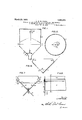
- F'gure 4 is a similar View showing the formation of a void or core in the mass of solids after :the discharge has been opened, as it occurs when no cont'roldevice is used, causing irregularity and often. stoppage of the discharge.
- Figure 5 is a similar view of the condition of the discharge when no packing of the material is taking place. 7
- Figure 6 is a similar view showing a binequipped with my invention and indicating the discharge of the mass-of solids therefrom, the sizes of the particles being exaggerated to more clearly disclose the Operation of the device. 7
- Figure 7 is an end elevation of a type of bin for containing and discharging solids which are of suflicient size and character to arch over in the bin.
- Figure 8 is a side elevation of the bin shown in Figure 7, and V Figure 9 is a cross section of the bin taken on the line 9-9, Figure 8.
- the plate 6 is; preferably circular
- a pipe or conduit 12 through which the air entrapped in the material discharges when the air is carried by the material below the edge of the plate.
- the other end of the pipe 112 is open-and is spaced from the material-containing space in the bin so that air may always freely discharge therefrom.
- a hood 13 over the open end of the pipe 12, or in'other ways cover the opening to deflect the material and air back into the bin and to prevent material introduced into the bin from entering the pipe.
- This bin is provided with inclined-bottom walls 14 and 15, and means are provided for sliding these walls upward to open the bottom of the bin for increasing distances to permit the material therein to discharge.
- the inclined walls 14 and 15 are provided on their lower ends at the edges of the Walls with extensions 16 which bear on rollers 17 disposed below the .bin.
- the Walls 14 and 15 are provided with racks 18 which are engaged by gears 19,7 which support the upper ends of the Walls and serve to move the walls in'the direction of their inclination.
- Means are provided for rotating the gears 19 simultaneously to cause both of the inclined-bottom walls to be raised simultaneously to open the bottom of the bin.
- a plate 21 Arranged within the bin above the pointof juncture of the inclined Walls is a plate 21 which serves the same function as the plate 6.
- the bottom walls are moved upwardly to open the bottom of I the bin and the material discharges through the outlet thus formed.
- the plate 21 prevents the finer material from the center of the bin from discharging first and causes the material to be discharged in a uniform mixture.
- the bottom walls 14: and 15 are gradually raised to increase the size of thedischarge opening to insure the discharge of all of the material from the bin.
- the side Walls 22 of the bin are preferably inclined inwardly so that the tendency of the shells to arch is obviated, thereby insuring the discharge of all of the shells from the bin.
- Iclaimz 1.
Description
March 20, 1928. 1,663,173
7 L. E. w. PIODA PROCESS OF AND APPARATUS FOR CONTROLLING THE MOVEMENT 0F MASSES OF soups 0F vARlous SIZES Filed Dec. 26. 1925 2 Sheets-Sheet 1 HE MOVEMENT ZES 2 Shee March 20, 1928.
L. E. W. PIODA PROCESS OF AND APPARATUS FOR CONTROLLING T 0F MASSES 0F SOLIDS OF VARIOUS SI ts-Sheet 2 Filed Dec. 26, 1923 gwuentoz H'add.
Patented Mar. 20, 1928.
httBd'ZB LOUIS E. W. PIODA, OF SAN FRANCISCO, CALIFORNIA.
PROCESS OF AND APIPARATUS FOR'CONTROLLING THE IVIOVEMENT'OF MASSES OF 7 SOLIDS OF VARIOUS SIZES.
Application filed December 26, 1923. Serial -No.-682,702.
The invention relates to a process of and an apparatus for controlling the movement of masses of solids of various sizes to preserve the uniformity of the mass.
An object of the invention isto provide a process of controlling the movement of masses of solids of various sizes to prevent segregation of the particles or pieces forming the mass in accordance with their variationvin size.
Another object of the'invention is to provide a process of controlling the discharge of a mass of solids of various sizes from a container so that the solids will discharge from the container in a uniform mixture and V in a uniform volume.
A further object of the invention is to provide an apparatus for controlling the movements of masses of solids of various sizes to prevent segregation of the particles or pieces in accordance with the relative size thereof.
The invention possesses other. advantageous features, some of which with the foregoing will be set forth at length in the following description, where I shall outline in full one form of the process of my invention and that formof'the apparatus which I have selected for illustration in the drawings accompanying and forming part of the present specification. In said drawings I have shown two forms of apparatus embodying my invention, but it is to be understood that I do not limit myself to such forms, since'the invention, as set forth in the claims, may be embodied in a plurality of other forms. The invention is applicable to the control of the movement of solids of various sizes and is not limited to use in connection with any particular solids or in any particular industry. In many industries, masses of solids of various sizes and particularly finely-divided solids, are stored in bins or containers from which they flow by gravity to other devices for further treatment. These bins are usually provided with sloping bottoms which are designed to discharge by gravity as much oftheir contents through the discharge aperture situated at the center of and at the lowest point of the bottom, as is possible. drical in shape and the bottoms are conical in shape and such bins are usually referred to as hopper-bottomed bins. The bins, how- These bins are frequently cylinever, are frequently square or rectangular and areprovided with flat bottoms.
i The solids of various sizes are delivered into these bins at the top, either from conveyors,conduits,spouts or other'devic'es. As
the material is delivered into the bin, the discharge outlet of the bin being closed, the
material builds up in a cone, the larger particles or pieces 1n the-mass of solids move outward toward the sides of the bin and the bottom up through the center, in the form- The finer of an inverted cone in the bin. particles which are disposed adjacent the center of thebin thus discharge first, formmg the inverted cone, and the coarser solids which are disposed adj acentthe sides of the bin, the support" is withdrawn, move into the inverted cone area and discharge last. Thus the material which discharges from the bin when the outlet is first opened, is of different character than the material which subsequently discharges, so that there is not a discharge of uniform mixture. Further, after the discharge starts, interruptions in the flow occur; the material may pack and core, causing it to cease flowing entirely, it may break down slowly, producing a decreased discharge, it may break down in larger masses, causing an increased dis charge, and after the'inverted cone is formed it may avalanche, into the inverted cone, causing a variation in the rateof discharge. The material discharged from the bin is usually fed to anotherdevice for further,
treatment and this other device is designed to handle material fed to it in uniform mixture and at a uniform rate, and when the.
mixture or the rate varies, the device becomes inefficient in performing its proper function. When the discharge outlet is first opened the device is fed with fine solids and subsequently with coarser solids, and during the feeding the rate of feed is varied due to the variation in the discharge rate from the bin, requiring corresponding adjustments of the device. This condition is particularly disadvantageous in the cement industry wherein a large volume of material must be discharged into' and released from bins and other containers and through many devices, the ultimate object being to produce a finely divided homogeneous mixture as nearly uni- 3 content, after being crushed, is passed from form in chemical and physical condition as possible. In this industry, in a typical dry process plant, as an example, the limestone the rock storage into drier bins whence it passes through the drier to the ball mill lated limestone bins.
bins. From the ball mill bins the material passes through the ball mills to the granu- From these bins it passes to the weighing machine bins, and thence through the weighing machine to the mixing machine, Where it is mixed with the clay, thence as a mixture to the tube mill bins.
The clay discharges from drier bins and pasesthrough the drier into ball mill bins whence it passes through the ball mills to the granulated clay bins, and thence to.
the weighing machine bins, through the weighing machines to the mixing machines, thence as a mixture to the tube mill bins. From the tube mill bins the mixture passes through the tube mills to the raw storage mix bins, thence to the kiln bins andthence to the kiln where it is burned to variable sized clinker, which passes to clinker storage. From the clinker storage the clinker passes to the clinker weighing machine bins, thence through the weighing machine with added gypsum to the ball mill bins, thence through the ball mills to the tube mill bins and thence through the tube mills to cement storage and thepacking bins and packing machines. It
is manifest therefore that the control of the movement of the large volume of material for uniformity, homogenity and regularity, which is dependent upon the discharge from the bins, is of the utmost importance in the cement industry and a most important factor in the efficient operation of the cement plant. At the present time, this necessitates the attention of a large force of men at the various bins who'follow the flow of the material and endeavor to maintain a substantially constant rate of discharge from the bins. xEven with such attention, however, they are unable to control the release of the material so that it is discharged regularly and uniformly.
If the speed of the material through a mill, such as a tube mill or ball mill, is irregular, frequent adjustments in the opera tion of the mill are necessary in order to make it function properly on the irregular character and supply of the material. When the material consists of fine particles, it will run freely and flood the mill, and when it consists of coarser particles it moves more slowly, arches, congests in the bins and slows up the mill production. In the discharge of fine material from bins, after the inverted cone has been formed in the material, the material avalanches and cascades into the space so formed, entrapping pockets of air in the mass, which are carried down and discharged through the outlet, causing irregularity in the rate of discharge through the outlet. This irregular discharge of the material through the outlet is disadvantageous, since it prevents uniforinreleaseof the material. Similar conditions exist when such material is fed from a bin into a rotary kiln, variations in the movement occuring, coring, arching, slowing and flooding taking place in the bin, causing corresponding conditions in the kiln, which entail irregular operation of the kiln, causing loss of time, waste of fuel," irregularity in the quantity and quality of clinker burned, decreased production, frequent adjustments in operation of the kiln and burners and excessive wear of kiln lining. Control of the movement of solids of various sizes to produce the discharge. of a uniform mixture at a uniform rate is therefore most important. In the manufacture of cement, it is important to maintain a uniform distribution of the finer particles throughout the raw mix, since in burning, the fine material, acting as a flux, reduces the temperature necessary to clinkering and consequently decreases the temperature necessary to produce cement.
In accordance with my invention I have provided means for causing the 'material to discharge from the bin in a uniform mixture and at a uniform rate, so that the feed to the mills, kilns or other devices is uniform. This obviates the necessity of employing a large number of men in an en-' deavor to regula-tethe movement, eliminates. the necessity of continual adjustments of the mills to accommodate the varying movement and varying character of the material and eliminates the necessity of constant alertness at the kilns to vary the speed of the kilns and the amount of fire, to prevent flooding the kilns or burning out the lining. In accordance with my invention I provide in each bin, adjacent'the outlet therefrom, means for causing the material to discharge from the bin in a uniform mixture, and at a uniform rate. This means preferably comprises a metallic plate or deflector ar-' ranged in the bin,"and is preferably placed directly over and spaced from the discharge outlet in such a manner as not to restrict the discharge capacity of the bin and/or out-' let, and so that the material passing to the outlet is drawn from a zone disposed between the side walls and the center of the bin. In this way the material passing to the outlet consists of a mixture of the coarser particles from adjacent the side walls and the finer particles from adjacent the center of-the bin and'this mixture re mains substantially constant during thedischargeofthe bin. The plate also acts to intercept the avalanches of the material so that the material not only discharges in a uniform mixture but also discharges at a uniform rate. When the fineness of-the material warrants it, means are also provided for releasing'entrapped air from the mass ofv the relative-size of the solids being exag-.
gerated.
F'gure 4 is a similar View showing the formation of a void or core in the mass of solids after :the discharge has been opened, as it occurs when no cont'roldevice is used, causing irregularity and often. stoppage of the discharge.
Figure 5 is a similar view of the condition of the discharge when no packing of the material is taking place. 7
.Figure 6 is a similar view showing a binequipped with my invention and indicating the discharge of the mass-of solids therefrom, the sizes of the particles being exaggerated to more clearly disclose the Operation of the device. 7
Figure 7 is an end elevation of a type of bin for containing and discharging solids which are of suflicient size and character to arch over in the bin.
Figure 8 is a side elevation of the bin shown in Figure 7, and V Figure 9 is a cross section of the bin taken on the line 9-9, Figure 8.
Referring particularly to Figure 3, it will be seen that as the stream of solids of various sizes is discharged into the bin through the conduit 2, that the solids build up in a cone in the bin and that the larger solids 3 congregate adjacent the side walls of the bin and that the finer solids 4 remain at the center of the bin. This condition occurs whenever a mass of solids of various sizes are discharged into a bin or container or other form of support. When the dischage outlet 5 is opened the material begins to discharge from the center of the bin, causing the finer particles to discharge first; This causes the format-ion of a core orvoid in the shape of an inverted cone in the material within the bin and as the support of the coarser material. adjacent the sides of the bin is diminished, such material moves in masses into the inverted cone area. This produces an irregular discharge of the material, the fine materials discharging first and the mixture gradually becoming more inverted cone has been coarse after the formed. These avalanches of material cause the entrapment of airpockets in-the mass and these air pockets, in passing through the outlet 5', cause irregularity in the rate of flow of the material. In accordance with my invention I arrange a'plate 6 in the bin 7 and spaced above the discharge outlet 5so that the material in discharging from the bin discharges in an annular zone surrounding the center-of the bin, so that the fine.
and coarse particles discharge together as is shown in Figure 6, thereby producing a uniform mixture ofthe discharging material. 'This material may dischargedirectly to the mill or kiln or may discharge onto a conveyor which carries it to the mill or kiln. in shape for cylindrical bins or square, =rectangular or irregular for square, rectangular or irregular bins, and is supported by the legs 9 on the hopper bottom 8, but it may be made of any desired shape, that is, either spherical or -conical,-and may be provided with saw-tooth or scalloped edges or may be otherwise Varied to control the discharge of the material from the bin.
material and prevent the airpockets from causing irregularity of discharge, I provide means for venting the air from the material. Arranged in the bin and extending through and opening on the under side of theplate The plate 6 is; preferably circular,
In order to relieve'the air entrapped in the 6 is a pipe or conduit 12 through which the air entrapped in the material discharges when the air is carried by the material below the edge of the plate. The other end of the pipe 112 is open-and is spaced from the material-containing space in the bin so that air may always freely discharge therefrom. I prefer to arrange a hood 13 over the open end of the pipe 12, or in'other ways cover the opening to deflect the material and air back into the bin and to prevent material introduced into the bin from entering the pipe.
I have ing cement from a submerged deposit of shells and clay and this material is extremely diflicult to handle in bins on account of the tendency of the shell to lodge and pack therein. The mixture of shells and clay will not discharge from an ordinary bin but will pack so solidly therein that it is extremely difficult to remove. To overcome this difficulty and to facilitate the handling of the mixture of shells and clay or of shells alone, I have providedthe bin shown in Figures 7 8 devised a process of manufacturand 9. This bin is designed not only to cause a discharge of the mixture of shells and clay but also to cause the discharge of the mixture at a uniform rate and as a substantially uniform mixture. This bin is provided with inclined- bottom walls 14 and 15, and means are provided for sliding these walls upward to open the bottom of the bin for increasing distances to permit the material therein to discharge. The inclined walls 14 and 15 are provided on their lower ends at the edges of the Walls with extensions 16 which bear on rollers 17 disposed below the .bin. The Walls 14 and 15 are provided with racks 18 which are engaged by gears 19,7 which support the upper ends of the Walls and serve to move the walls in'the direction of their inclination. Means are provided for rotating the gears 19 simultaneously to cause both of the inclined-bottom walls to be raised simultaneously to open the bottom of the bin. Arranged within the bin above the pointof juncture of the inclined Walls is a plate 21 which serves the same function as the plate 6. lVhen it is desired to discharge the material from the bin the bottom walls are moved upwardly to open the bottom of I the bin and the material discharges through the outlet thus formed. The plate 21 prevents the finer material from the center of the bin from discharging first and causes the material to be discharged in a uniform mixture. The bottom walls 14: and 15 are gradually raised to increase the size of thedischarge opening to insure the discharge of all of the material from the bin. The side Walls 22 of the bin are preferably inclined inwardly so that the tendency of the shells to arch is obviated, thereby insuring the discharge of all of the shells from the bin.
Iclaimz" 1. The process of controlling the gravital movement of a mass of relatively finely divided solids of various sizes from a conthereof, of a. plate arranged in the container above said outlet to cause the material to discharge in a uniform mixture and a pipe opening on the under side of the plate and through which trapped air may be discharged 3. The combinationv with a container adapted to contain solids of varioussizes and having a discharge outlet at the bottom thereof, of a plate arranged in the container above said outlet to cause the material to discharge in a uniform mixture and an open conduit connected to and opening on the under side of the plate, and having its other end spaced from the space in the container occupied by the material. i
4. The process of producingthe uniform flow of finely divided cement making materialthrough a cement mill which comprises flowing the material through containers and treatment apparatus in series and causing the material to discharge from the containers in a uniform mixture and at a uniform rate.
In testimony whereof, I have hereuntoset my hand.
LOUIS E. W. PIODA.
Priority Applications (1)
| Application Number | Priority Date | Filing Date | Title |
|---|---|---|---|
| US682702A US1663173A (en) | 1923-12-26 | 1923-12-26 | Process of and apparatus for controlling the movement of masses of solids of various sizes |
Applications Claiming Priority (1)
| Application Number | Priority Date | Filing Date | Title |
|---|---|---|---|
| US682702A US1663173A (en) | 1923-12-26 | 1923-12-26 | Process of and apparatus for controlling the movement of masses of solids of various sizes |
Publications (1)
| Publication Number | Publication Date |
|---|---|
| US1663173A true US1663173A (en) | 1928-03-20 |
Family
ID=24740779
Family Applications (1)
| Application Number | Title | Priority Date | Filing Date |
|---|---|---|---|
| US682702A Expired - Lifetime US1663173A (en) | 1923-12-26 | 1923-12-26 | Process of and apparatus for controlling the movement of masses of solids of various sizes |
Country Status (1)
| Country | Link |
|---|---|
| US (1) | US1663173A (en) |
Cited By (11)
| Publication number | Priority date | Publication date | Assignee | Title |
|---|---|---|---|---|
| US2608394A (en) * | 1951-08-01 | 1952-08-26 | Teichert & Son Inc A | Continuous mixer |
| US2729397A (en) * | 1956-01-03 | Weston | ||
| US2994460A (en) * | 1959-06-24 | 1961-08-01 | Max A Matthews | Blending hopper |
| US3078076A (en) * | 1960-01-19 | 1963-02-19 | Hardinge Co Inc | Method and means for segregating and recombining feed for grinding mill |
| US3167261A (en) * | 1961-12-04 | 1965-01-26 | Automatic Canteen Co | Coffee granulizing apparatus |
| EP0196105A2 (en) * | 1985-03-29 | 1986-10-01 | ULS International Inc. | Method and apparatus for handling particulate material |
| US4706854A (en) * | 1985-03-29 | 1987-11-17 | Uls International Inc. | Particulate material handling |
| US4754869A (en) * | 1987-05-22 | 1988-07-05 | Hutchison Donald S | Down flow distributor |
| FR2725701A1 (en) * | 1994-10-12 | 1996-04-19 | Cochery Bourdin Chausse | Granular material distribution hopper |
| US20080062812A1 (en) * | 2006-03-16 | 2008-03-13 | Murphy Braden | Apparatus and method for premixing lost circulation material |
| US20100271902A1 (en) * | 2006-03-16 | 2010-10-28 | Murphy Braden | Apparatus and method for premixing lost circulation material |
-
1923
- 1923-12-26 US US682702A patent/US1663173A/en not_active Expired - Lifetime
Cited By (12)
| Publication number | Priority date | Publication date | Assignee | Title |
|---|---|---|---|---|
| US2729397A (en) * | 1956-01-03 | Weston | ||
| US2608394A (en) * | 1951-08-01 | 1952-08-26 | Teichert & Son Inc A | Continuous mixer |
| US2994460A (en) * | 1959-06-24 | 1961-08-01 | Max A Matthews | Blending hopper |
| US3078076A (en) * | 1960-01-19 | 1963-02-19 | Hardinge Co Inc | Method and means for segregating and recombining feed for grinding mill |
| US3167261A (en) * | 1961-12-04 | 1965-01-26 | Automatic Canteen Co | Coffee granulizing apparatus |
| EP0196105A2 (en) * | 1985-03-29 | 1986-10-01 | ULS International Inc. | Method and apparatus for handling particulate material |
| US4706854A (en) * | 1985-03-29 | 1987-11-17 | Uls International Inc. | Particulate material handling |
| EP0196105A3 (en) * | 1985-03-29 | 1988-03-30 | ULS International Inc. | Method and apparatus for handling particulate material |
| US4754869A (en) * | 1987-05-22 | 1988-07-05 | Hutchison Donald S | Down flow distributor |
| FR2725701A1 (en) * | 1994-10-12 | 1996-04-19 | Cochery Bourdin Chausse | Granular material distribution hopper |
| US20080062812A1 (en) * | 2006-03-16 | 2008-03-13 | Murphy Braden | Apparatus and method for premixing lost circulation material |
| US20100271902A1 (en) * | 2006-03-16 | 2010-10-28 | Murphy Braden | Apparatus and method for premixing lost circulation material |
Similar Documents
| Publication | Publication Date | Title |
|---|---|---|
| US1663173A (en) | Process of and apparatus for controlling the movement of masses of solids of various sizes | |
| AU775396B2 (en) | Equipment for the even feed of pulverous material to a concentrate burner of suspension smelting furnace | |
| US2192287A (en) | Apparatus for feeding finely divided material | |
| US2574231A (en) | Apparatus having rotatable means for feeding aeratable powdered material from storageand dispensing such material | |
| US2861353A (en) | Apparatus for cooling granular materials | |
| US3148865A (en) | Pneumatic conveying and conditioning method and apparatus | |
| CN109821476A (en) | A kind of flyash in great mixed amount balling-up granulating system and balling-up prilling process | |
| US3140326A (en) | Agglomerating method and apparatus | |
| US2984861A (en) | Balling drum | |
| US1960797A (en) | Storage bin | |
| US3945615A (en) | Continuous method and device for withdrawing particulate material from a container | |
| US2686617A (en) | Method of and apparatus for discharging pulverulent material from bins | |
| US1947487A (en) | Mixing apparatus | |
| US3438520A (en) | Slug filling of bins | |
| US2876489A (en) | Combination system of mixing materials and deep sinter bed charging | |
| US3294292A (en) | Blending of granular materials | |
| US1867489A (en) | Means for storing and supplying glass batches of uniform mixture | |
| US2863575A (en) | Storage hoppers | |
| US1332938A (en) | Mixing apparatus | |
| US533488A (en) | Machine for manufacturing artificial fuel | |
| US1988531A (en) | Hopper, chute, and the like for feeding lumpy, granular, or pulverulent material | |
| US3148864A (en) | Pneumatic conveying and reclaiming method and apparatus | |
| SU962727A1 (en) | Shaft furnace charging apparatus | |
| US2743534A (en) | Apparatus for cooling sinter | |
| US1239179A (en) | Machinery for agglomerating ore. |