US11958504B2 - Method and apparatus for controlling a vehicle's driving operation using advance information - Google Patents
Method and apparatus for controlling a vehicle's driving operation using advance information Download PDFInfo
- Publication number
- US11958504B2 US11958504B2 US16/875,429 US202016875429A US11958504B2 US 11958504 B2 US11958504 B2 US 11958504B2 US 202016875429 A US202016875429 A US 202016875429A US 11958504 B2 US11958504 B2 US 11958504B2
- Authority
- US
- United States
- Prior art keywords
- driving
- vehicle
- information
- road
- lane
- Prior art date
- Legal status (The legal status is an assumption and is not a legal conclusion. Google has not performed a legal analysis and makes no representation as to the accuracy of the status listed.)
- Active
Links
- 238000000034 method Methods 0.000 title claims abstract description 45
- 230000008859 change Effects 0.000 claims description 24
- 238000012360 testing method Methods 0.000 claims description 9
- 238000004458 analytical method Methods 0.000 claims description 2
- 230000004044 response Effects 0.000 claims 1
- 238000004891 communication Methods 0.000 description 18
- 230000006870 function Effects 0.000 description 4
- 230000008901 benefit Effects 0.000 description 3
- 238000010276 construction Methods 0.000 description 3
- 238000001514 detection method Methods 0.000 description 3
- 238000005516 engineering process Methods 0.000 description 3
- 238000010295 mobile communication Methods 0.000 description 3
- 230000003068 static effect Effects 0.000 description 3
- 230000009471 action Effects 0.000 description 2
- 230000003920 cognitive function Effects 0.000 description 2
- 238000010586 diagram Methods 0.000 description 2
- 238000007500 overflow downdraw method Methods 0.000 description 2
- 230000008569 process Effects 0.000 description 2
- 238000012545 processing Methods 0.000 description 2
- 230000001133 acceleration Effects 0.000 description 1
- 230000004888 barrier function Effects 0.000 description 1
- 230000005540 biological transmission Effects 0.000 description 1
- 238000004364 calculation method Methods 0.000 description 1
- 238000006243 chemical reaction Methods 0.000 description 1
- 230000008878 coupling Effects 0.000 description 1
- 238000010168 coupling process Methods 0.000 description 1
- 238000005859 coupling reaction Methods 0.000 description 1
- 230000003111 delayed effect Effects 0.000 description 1
- 238000011156 evaluation Methods 0.000 description 1
- 230000002349 favourable effect Effects 0.000 description 1
- 230000004927 fusion Effects 0.000 description 1
- 239000011159 matrix material Substances 0.000 description 1
- 238000012986 modification Methods 0.000 description 1
- 230000004048 modification Effects 0.000 description 1
- 230000003287 optical effect Effects 0.000 description 1
- 238000006467 substitution reaction Methods 0.000 description 1
- 238000012549 training Methods 0.000 description 1
- 230000000007 visual effect Effects 0.000 description 1
Images


Classifications
-
- B—PERFORMING OPERATIONS; TRANSPORTING
- B60—VEHICLES IN GENERAL
- B60W—CONJOINT CONTROL OF VEHICLE SUB-UNITS OF DIFFERENT TYPE OR DIFFERENT FUNCTION; CONTROL SYSTEMS SPECIALLY ADAPTED FOR HYBRID VEHICLES; ROAD VEHICLE DRIVE CONTROL SYSTEMS FOR PURPOSES NOT RELATED TO THE CONTROL OF A PARTICULAR SUB-UNIT
- B60W60/00—Drive control systems specially adapted for autonomous road vehicles
- B60W60/001—Planning or execution of driving tasks
- B60W60/0015—Planning or execution of driving tasks specially adapted for safety
- B60W60/0016—Planning or execution of driving tasks specially adapted for safety of the vehicle or its occupants
-
- B—PERFORMING OPERATIONS; TRANSPORTING
- B60—VEHICLES IN GENERAL
- B60W—CONJOINT CONTROL OF VEHICLE SUB-UNITS OF DIFFERENT TYPE OR DIFFERENT FUNCTION; CONTROL SYSTEMS SPECIALLY ADAPTED FOR HYBRID VEHICLES; ROAD VEHICLE DRIVE CONTROL SYSTEMS FOR PURPOSES NOT RELATED TO THE CONTROL OF A PARTICULAR SUB-UNIT
- B60W30/00—Purposes of road vehicle drive control systems not related to the control of a particular sub-unit, e.g. of systems using conjoint control of vehicle sub-units, or advanced driver assistance systems for ensuring comfort, stability and safety or drive control systems for propelling or retarding the vehicle
- B60W30/14—Adaptive cruise control
- B60W30/143—Speed control
-
- B—PERFORMING OPERATIONS; TRANSPORTING
- B60—VEHICLES IN GENERAL
- B60W—CONJOINT CONTROL OF VEHICLE SUB-UNITS OF DIFFERENT TYPE OR DIFFERENT FUNCTION; CONTROL SYSTEMS SPECIALLY ADAPTED FOR HYBRID VEHICLES; ROAD VEHICLE DRIVE CONTROL SYSTEMS FOR PURPOSES NOT RELATED TO THE CONTROL OF A PARTICULAR SUB-UNIT
- B60W30/00—Purposes of road vehicle drive control systems not related to the control of a particular sub-unit, e.g. of systems using conjoint control of vehicle sub-units, or advanced driver assistance systems for ensuring comfort, stability and safety or drive control systems for propelling or retarding the vehicle
- B60W30/14—Adaptive cruise control
-
- B—PERFORMING OPERATIONS; TRANSPORTING
- B60—VEHICLES IN GENERAL
- B60W—CONJOINT CONTROL OF VEHICLE SUB-UNITS OF DIFFERENT TYPE OR DIFFERENT FUNCTION; CONTROL SYSTEMS SPECIALLY ADAPTED FOR HYBRID VEHICLES; ROAD VEHICLE DRIVE CONTROL SYSTEMS FOR PURPOSES NOT RELATED TO THE CONTROL OF A PARTICULAR SUB-UNIT
- B60W10/00—Conjoint control of vehicle sub-units of different type or different function
- B60W10/04—Conjoint control of vehicle sub-units of different type or different function including control of propulsion units
-
- B—PERFORMING OPERATIONS; TRANSPORTING
- B60—VEHICLES IN GENERAL
- B60W—CONJOINT CONTROL OF VEHICLE SUB-UNITS OF DIFFERENT TYPE OR DIFFERENT FUNCTION; CONTROL SYSTEMS SPECIALLY ADAPTED FOR HYBRID VEHICLES; ROAD VEHICLE DRIVE CONTROL SYSTEMS FOR PURPOSES NOT RELATED TO THE CONTROL OF A PARTICULAR SUB-UNIT
- B60W30/00—Purposes of road vehicle drive control systems not related to the control of a particular sub-unit, e.g. of systems using conjoint control of vehicle sub-units, or advanced driver assistance systems for ensuring comfort, stability and safety or drive control systems for propelling or retarding the vehicle
- B60W30/08—Active safety systems predicting or avoiding probable or impending collision or attempting to minimise its consequences
- B60W30/09—Taking automatic action to avoid collision, e.g. braking and steering
-
- B—PERFORMING OPERATIONS; TRANSPORTING
- B60—VEHICLES IN GENERAL
- B60W—CONJOINT CONTROL OF VEHICLE SUB-UNITS OF DIFFERENT TYPE OR DIFFERENT FUNCTION; CONTROL SYSTEMS SPECIALLY ADAPTED FOR HYBRID VEHICLES; ROAD VEHICLE DRIVE CONTROL SYSTEMS FOR PURPOSES NOT RELATED TO THE CONTROL OF A PARTICULAR SUB-UNIT
- B60W30/00—Purposes of road vehicle drive control systems not related to the control of a particular sub-unit, e.g. of systems using conjoint control of vehicle sub-units, or advanced driver assistance systems for ensuring comfort, stability and safety or drive control systems for propelling or retarding the vehicle
- B60W30/08—Active safety systems predicting or avoiding probable or impending collision or attempting to minimise its consequences
- B60W30/095—Predicting travel path or likelihood of collision
- B60W30/0953—Predicting travel path or likelihood of collision the prediction being responsive to vehicle dynamic parameters
-
- B—PERFORMING OPERATIONS; TRANSPORTING
- B60—VEHICLES IN GENERAL
- B60W—CONJOINT CONTROL OF VEHICLE SUB-UNITS OF DIFFERENT TYPE OR DIFFERENT FUNCTION; CONTROL SYSTEMS SPECIALLY ADAPTED FOR HYBRID VEHICLES; ROAD VEHICLE DRIVE CONTROL SYSTEMS FOR PURPOSES NOT RELATED TO THE CONTROL OF A PARTICULAR SUB-UNIT
- B60W30/00—Purposes of road vehicle drive control systems not related to the control of a particular sub-unit, e.g. of systems using conjoint control of vehicle sub-units, or advanced driver assistance systems for ensuring comfort, stability and safety or drive control systems for propelling or retarding the vehicle
- B60W30/08—Active safety systems predicting or avoiding probable or impending collision or attempting to minimise its consequences
- B60W30/095—Predicting travel path or likelihood of collision
- B60W30/0956—Predicting travel path or likelihood of collision the prediction being responsive to traffic or environmental parameters
-
- B—PERFORMING OPERATIONS; TRANSPORTING
- B60—VEHICLES IN GENERAL
- B60W—CONJOINT CONTROL OF VEHICLE SUB-UNITS OF DIFFERENT TYPE OR DIFFERENT FUNCTION; CONTROL SYSTEMS SPECIALLY ADAPTED FOR HYBRID VEHICLES; ROAD VEHICLE DRIVE CONTROL SYSTEMS FOR PURPOSES NOT RELATED TO THE CONTROL OF A PARTICULAR SUB-UNIT
- B60W30/00—Purposes of road vehicle drive control systems not related to the control of a particular sub-unit, e.g. of systems using conjoint control of vehicle sub-units, or advanced driver assistance systems for ensuring comfort, stability and safety or drive control systems for propelling or retarding the vehicle
- B60W30/18—Propelling the vehicle
- B60W30/18009—Propelling the vehicle related to particular drive situations
- B60W30/18159—Traversing an intersection
-
- B—PERFORMING OPERATIONS; TRANSPORTING
- B60—VEHICLES IN GENERAL
- B60W—CONJOINT CONTROL OF VEHICLE SUB-UNITS OF DIFFERENT TYPE OR DIFFERENT FUNCTION; CONTROL SYSTEMS SPECIALLY ADAPTED FOR HYBRID VEHICLES; ROAD VEHICLE DRIVE CONTROL SYSTEMS FOR PURPOSES NOT RELATED TO THE CONTROL OF A PARTICULAR SUB-UNIT
- B60W30/00—Purposes of road vehicle drive control systems not related to the control of a particular sub-unit, e.g. of systems using conjoint control of vehicle sub-units, or advanced driver assistance systems for ensuring comfort, stability and safety or drive control systems for propelling or retarding the vehicle
- B60W30/18—Propelling the vehicle
- B60W30/18009—Propelling the vehicle related to particular drive situations
- B60W30/18163—Lane change; Overtaking manoeuvres
-
- B—PERFORMING OPERATIONS; TRANSPORTING
- B60—VEHICLES IN GENERAL
- B60W—CONJOINT CONTROL OF VEHICLE SUB-UNITS OF DIFFERENT TYPE OR DIFFERENT FUNCTION; CONTROL SYSTEMS SPECIALLY ADAPTED FOR HYBRID VEHICLES; ROAD VEHICLE DRIVE CONTROL SYSTEMS FOR PURPOSES NOT RELATED TO THE CONTROL OF A PARTICULAR SUB-UNIT
- B60W40/00—Estimation or calculation of non-directly measurable driving parameters for road vehicle drive control systems not related to the control of a particular sub unit, e.g. by using mathematical models
- B60W40/02—Estimation or calculation of non-directly measurable driving parameters for road vehicle drive control systems not related to the control of a particular sub unit, e.g. by using mathematical models related to ambient conditions
-
- B—PERFORMING OPERATIONS; TRANSPORTING
- B60—VEHICLES IN GENERAL
- B60W—CONJOINT CONTROL OF VEHICLE SUB-UNITS OF DIFFERENT TYPE OR DIFFERENT FUNCTION; CONTROL SYSTEMS SPECIALLY ADAPTED FOR HYBRID VEHICLES; ROAD VEHICLE DRIVE CONTROL SYSTEMS FOR PURPOSES NOT RELATED TO THE CONTROL OF A PARTICULAR SUB-UNIT
- B60W40/00—Estimation or calculation of non-directly measurable driving parameters for road vehicle drive control systems not related to the control of a particular sub unit, e.g. by using mathematical models
- B60W40/10—Estimation or calculation of non-directly measurable driving parameters for road vehicle drive control systems not related to the control of a particular sub unit, e.g. by using mathematical models related to vehicle motion
- B60W40/105—Speed
-
- B—PERFORMING OPERATIONS; TRANSPORTING
- B60—VEHICLES IN GENERAL
- B60W—CONJOINT CONTROL OF VEHICLE SUB-UNITS OF DIFFERENT TYPE OR DIFFERENT FUNCTION; CONTROL SYSTEMS SPECIALLY ADAPTED FOR HYBRID VEHICLES; ROAD VEHICLE DRIVE CONTROL SYSTEMS FOR PURPOSES NOT RELATED TO THE CONTROL OF A PARTICULAR SUB-UNIT
- B60W50/00—Details of control systems for road vehicle drive control not related to the control of a particular sub-unit, e.g. process diagnostic or vehicle driver interfaces
- B60W50/0097—Predicting future conditions
-
- B—PERFORMING OPERATIONS; TRANSPORTING
- B60—VEHICLES IN GENERAL
- B60W—CONJOINT CONTROL OF VEHICLE SUB-UNITS OF DIFFERENT TYPE OR DIFFERENT FUNCTION; CONTROL SYSTEMS SPECIALLY ADAPTED FOR HYBRID VEHICLES; ROAD VEHICLE DRIVE CONTROL SYSTEMS FOR PURPOSES NOT RELATED TO THE CONTROL OF A PARTICULAR SUB-UNIT
- B60W50/00—Details of control systems for road vehicle drive control not related to the control of a particular sub-unit, e.g. process diagnostic or vehicle driver interfaces
- B60W50/08—Interaction between the driver and the control system
- B60W50/14—Means for informing the driver, warning the driver or prompting a driver intervention
-
- G—PHYSICS
- G01—MEASURING; TESTING
- G01C—MEASURING DISTANCES, LEVELS OR BEARINGS; SURVEYING; NAVIGATION; GYROSCOPIC INSTRUMENTS; PHOTOGRAMMETRY OR VIDEOGRAMMETRY
- G01C21/00—Navigation; Navigational instruments not provided for in groups G01C1/00 - G01C19/00
- G01C21/26—Navigation; Navigational instruments not provided for in groups G01C1/00 - G01C19/00 specially adapted for navigation in a road network
- G01C21/34—Route searching; Route guidance
- G01C21/3407—Route searching; Route guidance specially adapted for specific applications
-
- G—PHYSICS
- G01—MEASURING; TESTING
- G01C—MEASURING DISTANCES, LEVELS OR BEARINGS; SURVEYING; NAVIGATION; GYROSCOPIC INSTRUMENTS; PHOTOGRAMMETRY OR VIDEOGRAMMETRY
- G01C21/00—Navigation; Navigational instruments not provided for in groups G01C1/00 - G01C19/00
- G01C21/26—Navigation; Navigational instruments not provided for in groups G01C1/00 - G01C19/00 specially adapted for navigation in a road network
- G01C21/34—Route searching; Route guidance
- G01C21/3453—Special cost functions, i.e. other than distance or default speed limit of road segments
-
- G—PHYSICS
- G01—MEASURING; TESTING
- G01C—MEASURING DISTANCES, LEVELS OR BEARINGS; SURVEYING; NAVIGATION; GYROSCOPIC INSTRUMENTS; PHOTOGRAMMETRY OR VIDEOGRAMMETRY
- G01C21/00—Navigation; Navigational instruments not provided for in groups G01C1/00 - G01C19/00
- G01C21/26—Navigation; Navigational instruments not provided for in groups G01C1/00 - G01C19/00 specially adapted for navigation in a road network
- G01C21/34—Route searching; Route guidance
- G01C21/36—Input/output arrangements for on-board computers
- G01C21/3691—Retrieval, searching and output of information related to real-time traffic, weather, or environmental conditions
-
- G—PHYSICS
- G05—CONTROLLING; REGULATING
- G05D—SYSTEMS FOR CONTROLLING OR REGULATING NON-ELECTRIC VARIABLES
- G05D1/00—Control of position, course or altitude of land, water, air, or space vehicles, e.g. automatic pilot
- G05D1/0088—Control of position, course or altitude of land, water, air, or space vehicles, e.g. automatic pilot characterized by the autonomous decision making process, e.g. artificial intelligence, predefined behaviours
-
- G—PHYSICS
- G05—CONTROLLING; REGULATING
- G05D—SYSTEMS FOR CONTROLLING OR REGULATING NON-ELECTRIC VARIABLES
- G05D1/00—Control of position, course or altitude of land, water, air, or space vehicles, e.g. automatic pilot
- G05D1/02—Control of position or course in two dimensions
- G05D1/021—Control of position or course in two dimensions specially adapted to land vehicles
- G05D1/0268—Control of position or course in two dimensions specially adapted to land vehicles using internal positioning means
- G05D1/0274—Control of position or course in two dimensions specially adapted to land vehicles using internal positioning means using mapping information stored in a memory device
-
- B—PERFORMING OPERATIONS; TRANSPORTING
- B60—VEHICLES IN GENERAL
- B60W—CONJOINT CONTROL OF VEHICLE SUB-UNITS OF DIFFERENT TYPE OR DIFFERENT FUNCTION; CONTROL SYSTEMS SPECIALLY ADAPTED FOR HYBRID VEHICLES; ROAD VEHICLE DRIVE CONTROL SYSTEMS FOR PURPOSES NOT RELATED TO THE CONTROL OF A PARTICULAR SUB-UNIT
- B60W2520/00—Input parameters relating to overall vehicle dynamics
- B60W2520/10—Longitudinal speed
-
- B—PERFORMING OPERATIONS; TRANSPORTING
- B60—VEHICLES IN GENERAL
- B60W—CONJOINT CONTROL OF VEHICLE SUB-UNITS OF DIFFERENT TYPE OR DIFFERENT FUNCTION; CONTROL SYSTEMS SPECIALLY ADAPTED FOR HYBRID VEHICLES; ROAD VEHICLE DRIVE CONTROL SYSTEMS FOR PURPOSES NOT RELATED TO THE CONTROL OF A PARTICULAR SUB-UNIT
- B60W2552/00—Input parameters relating to infrastructure
- B60W2552/10—Number of lanes
-
- B—PERFORMING OPERATIONS; TRANSPORTING
- B60—VEHICLES IN GENERAL
- B60W—CONJOINT CONTROL OF VEHICLE SUB-UNITS OF DIFFERENT TYPE OR DIFFERENT FUNCTION; CONTROL SYSTEMS SPECIALLY ADAPTED FOR HYBRID VEHICLES; ROAD VEHICLE DRIVE CONTROL SYSTEMS FOR PURPOSES NOT RELATED TO THE CONTROL OF A PARTICULAR SUB-UNIT
- B60W2552/00—Input parameters relating to infrastructure
- B60W2552/45—Pedestrian sidewalk
-
- B—PERFORMING OPERATIONS; TRANSPORTING
- B60—VEHICLES IN GENERAL
- B60W—CONJOINT CONTROL OF VEHICLE SUB-UNITS OF DIFFERENT TYPE OR DIFFERENT FUNCTION; CONTROL SYSTEMS SPECIALLY ADAPTED FOR HYBRID VEHICLES; ROAD VEHICLE DRIVE CONTROL SYSTEMS FOR PURPOSES NOT RELATED TO THE CONTROL OF A PARTICULAR SUB-UNIT
- B60W2552/00—Input parameters relating to infrastructure
- B60W2552/53—Road markings, e.g. lane marker or crosswalk
-
- B—PERFORMING OPERATIONS; TRANSPORTING
- B60—VEHICLES IN GENERAL
- B60W—CONJOINT CONTROL OF VEHICLE SUB-UNITS OF DIFFERENT TYPE OR DIFFERENT FUNCTION; CONTROL SYSTEMS SPECIALLY ADAPTED FOR HYBRID VEHICLES; ROAD VEHICLE DRIVE CONTROL SYSTEMS FOR PURPOSES NOT RELATED TO THE CONTROL OF A PARTICULAR SUB-UNIT
- B60W2554/00—Input parameters relating to objects
-
- B—PERFORMING OPERATIONS; TRANSPORTING
- B60—VEHICLES IN GENERAL
- B60W—CONJOINT CONTROL OF VEHICLE SUB-UNITS OF DIFFERENT TYPE OR DIFFERENT FUNCTION; CONTROL SYSTEMS SPECIALLY ADAPTED FOR HYBRID VEHICLES; ROAD VEHICLE DRIVE CONTROL SYSTEMS FOR PURPOSES NOT RELATED TO THE CONTROL OF A PARTICULAR SUB-UNIT
- B60W2555/00—Input parameters relating to exterior conditions, not covered by groups B60W2552/00, B60W2554/00
- B60W2555/60—Traffic rules, e.g. speed limits or right of way
-
- B—PERFORMING OPERATIONS; TRANSPORTING
- B60—VEHICLES IN GENERAL
- B60W—CONJOINT CONTROL OF VEHICLE SUB-UNITS OF DIFFERENT TYPE OR DIFFERENT FUNCTION; CONTROL SYSTEMS SPECIALLY ADAPTED FOR HYBRID VEHICLES; ROAD VEHICLE DRIVE CONTROL SYSTEMS FOR PURPOSES NOT RELATED TO THE CONTROL OF A PARTICULAR SUB-UNIT
- B60W2556/00—Input parameters relating to data
- B60W2556/45—External transmission of data to or from the vehicle
- B60W2556/50—External transmission of data to or from the vehicle for navigation systems
-
- B—PERFORMING OPERATIONS; TRANSPORTING
- B60—VEHICLES IN GENERAL
- B60W—CONJOINT CONTROL OF VEHICLE SUB-UNITS OF DIFFERENT TYPE OR DIFFERENT FUNCTION; CONTROL SYSTEMS SPECIALLY ADAPTED FOR HYBRID VEHICLES; ROAD VEHICLE DRIVE CONTROL SYSTEMS FOR PURPOSES NOT RELATED TO THE CONTROL OF A PARTICULAR SUB-UNIT
- B60W2720/00—Output or target parameters relating to overall vehicle dynamics
- B60W2720/10—Longitudinal speed
-
- B—PERFORMING OPERATIONS; TRANSPORTING
- B60—VEHICLES IN GENERAL
- B60Y—INDEXING SCHEME RELATING TO ASPECTS CROSS-CUTTING VEHICLE TECHNOLOGY
- B60Y2300/00—Purposes or special features of road vehicle drive control systems
- B60Y2300/08—Predicting or avoiding probable or impending collision
-
- B—PERFORMING OPERATIONS; TRANSPORTING
- B60—VEHICLES IN GENERAL
- B60Y—INDEXING SCHEME RELATING TO ASPECTS CROSS-CUTTING VEHICLE TECHNOLOGY
- B60Y2300/00—Purposes or special features of road vehicle drive control systems
- B60Y2300/14—Cruise control
-
- G—PHYSICS
- G06—COMPUTING; CALCULATING OR COUNTING
- G06T—IMAGE DATA PROCESSING OR GENERATION, IN GENERAL
- G06T2207/00—Indexing scheme for image analysis or image enhancement
- G06T2207/30—Subject of image; Context of image processing
- G06T2207/30248—Vehicle exterior or interior
- G06T2207/30252—Vehicle exterior; Vicinity of vehicle
- G06T2207/30261—Obstacle
Definitions
- Embodiments are related to a method and apparatus for controlling driving of a vehicle using advance information, and more specifically, to performing fast and stable autonomous driving using a target speed previously determined according to an attribute of a road.
- Autonomous driving vehicles refer to vehicles that recognize a surrounding environment without a driver's intervention and automatically drive by themselves to a given destination according to the recognized surrounding environment.
- a global route (a trajectory composed of location information) that is an optimal route to a destination is derived on a given map, and driving of the vehicle is controlled to operate along the derived global route.
- vehicle autonomous driving systems unlike navigation systems provided in vehicles, require a detailed map at a lane level, and constructing the map is expensive.
- a navigation algorithm of the existing vehicle is applied to the detailed map, calculating an initial route takes a great deal of time.
- the vehicle may stop or move to an unplanned road, which may cause a dangerous situation.
- the existing driving control method for obstacle detection and avoidance through sensor detection has a difficulty in clearly identifying the characteristics of the obstacle, and a delay in reflecting a real-time sensing result, which cause difficulty in smooth driving.
- the present invention provides an autonomous driving method and apparatus for a vehicle that is capable of deriving the optimal route in a short time using preset local information in which road attribute information, user experience information, and the like are reflected.
- a method of controlling driving of a vehicle using advance information including: acquiring preset local information including a road name, a road section, a road attribute, a location of a building, a lane, a traffic signal, and obstacle information for a predetermined region; acquiring a driving experience value resulting from a previous drive using the local information, and setting a target speed corresponding to the road attribute using the driving experience value; determining a driving state and a driving speed of the vehicle on the basis of the local information, and the target speed, of a current position of the vehicle; and generating a driving control command corresponding to the driving state and the driving speed of the vehicle.
- an apparatus for controlling driving of a vehicle using advance information including a processor and a memory storing instructions executable by the processor, wherein the processor executes the instructions to: acquire preset local information including a road name, a road section, a road attribute, a location of a building, a lane, a traffic signal, and obstacle information for a predetermined region; acquire a driving experience value resulting from a previous drive using the local information, and set a target speed corresponding to the road attribute using the driving experience value; determine a driving state and a driving speed of the vehicle on the basis of the local information, and the target speed, of a current position of the vehicle; and generate a driving control command corresponding to the driving state and the driving speed of the vehicle.
- a non-transitory computer-readable storage medium configured to store instructions executable by a processor to execute a method of controlling driving of a vehicle using advance information.
- FIG. 1 is a view for schematically describing a method of controlling driving of a vehicle using advance information according to one disclosure
- FIG. 2 is a flowchart for describing a method of controlling driving of a vehicle using advance information according to one disclosure
- FIG. 3 is a view for describing a specific example of driving control being performed using advance information according to one disclosure
- FIG. 4 is a view for describing a feature for controlling the driving of the vehicle using a driving state of the vehicle according to one disclosure
- FIG. 5 is a view for describing a feature for generating a driving route of a vehicle by dividing a lane into grids according to one disclosure
- FIG. 6 is a view for describing an example of autonomous driving of a vehicle being performed using traffic signal information according to one disclosure.
- FIG. 7 is a block diagram illustrating a configuration of an apparatus for controlling driving of a vehicle using advance information according to one disclosure.
- connection or coupling used to designate a connection or coupling of one element to another element includes both a case in which the element is “directly connected to” or “directly coupled to” another element and a case in which the element is “electronically connected to” or “electronically coupled to” another element via still another element.
- the term “comprises” or “includes” and/or “comprising” or “including” means that one or more other components, steps, operation and/or existence or addition of elements are not excluded in addition to the described components, steps, operation and/or elements unless context dictates otherwise.
- an apparatus 100 for controlling driving of a vehicle using advance information is referred to as a vehicle driving control apparatus 100 for brevity.
- a user refers to a person who uses the vehicle driving control apparatus 100 and may include a developer, a driver of a vehicle, a passenger, an owner, and the like, and may include all persons who directly or indirectly use the vehicle driving control apparatus 100 .
- FIG. 1 is a view for schematically describing a method of controlling driving of a vehicle using advance information according to one disclosure.
- the vehicle driving control apparatus 100 may be installed inside or outside a vehicle 1000 .
- the vehicle driving control apparatus 100 may be included in the vehicle 1000 as a part thereof and may be mounted as a component independent of the vehicle 1000 .
- the vehicle driving control apparatus 100 may operate using parts included in the vehicle 1000 .
- the vehicle driving control apparatus 100 may obtain information required for autonomous driving by communicating with a camera, a driving device, a steering device, and a sensor unit installed in the vehicle 1000 or may control parts of the vehicle 1000 required for autonomous driving.
- the vehicle driving control apparatus 100 may provide a method of efficiently performing autonomous driving in an already-known place by actively utilizing information collected in advance.
- the vehicle driving control apparatus 100 may perform autonomous driving of the vehicle using pieces of information involved in a road, in particular, advance information related to road attributes. Accordingly, the vehicle driving control apparatus 100 may perform efficient autonomous driving while saving time by determining obstacles using sensors and determining road attributes using real time determination.
- the road attribute include at least one of the number of lanes, a stop line, a crosswalk, a speed limit, an intersection, a U-turn, a road entry/exit point, a road junction, a road fork, a building access road, a speed bump, and a protected area of the road.
- the road attributes shown in FIG. 1 include i) a section 1001 in which a two-lane road is narrowed to a one-lane road and ii) a speed bump 1002 installed on the first lane of the road.
- the vehicle driving control apparatus 100 may be included in the vehicle 1000 driving in the second lane.
- the vehicle driving control apparatus 100 may acquire the section 1001 in which the two-lane road is narrowed to the one-lane road through advance map information (or preset local information). Accordingly, the vehicle driving control apparatus 100 may control the vehicle 1000 to move the vehicle 1000 in a direction toward the first lane. That is, since the vehicle driving control apparatus 100 already identifies the location of the section 1001 of the road in which the lanes are reduced, the vehicle driving control apparatus 100 obtains information about the current location of the vehicle 1000 and controls the vehicle 1000 to change lanes before appearance of the section 1001 of the road being narrowed. That is, the vehicle 1000 may save time for determining the attributes of the road and improve reliability regarding accurate determination.
- the vehicle driving control apparatus 100 may acquire information related to the speed bump 1002 while driving along the one-lane road.
- the vehicle driving control apparatus 100 may identify the location of the speed bump 1002 using pre-trained driving information.
- the vehicle driving control apparatus 100 may acquire information about riding comfort when passing through the speed bump 1002 through pre-training.
- the information about riding comfort represents an optimal riding comfort state determined by analyzing pieces of information about riding comfort of the user or vibration data when the vehicle 1000 passes the speed bump 1002 at different speeds.
- the vehicle driving control apparatus 100 may provide an autonomous driving method customized for each road attribute by reflecting a driving experience value of the user.
- the local information may not only include a target speed, which refers to an optimal speed at each point, but may also include information about a desirable route to be traveled on by the vehicle in practice.
- driving on the center of a lane is generally desirable, but this is not the case at all times.
- the local information is used to determine a desired route to be traveled by the vehicle.
- information indicating whether a turn signal lamp is turned on/off according to a driving state of the vehicle in each location, a desired lane change route, traffic light related information, information on driving suitability (or the score for the driving state) according to the position, direction, and speed of the vehicle may be stored in advance in the local information. For example, driving in reverse and stopping in a crosswalk and an intersection are undesirable, and information corresponding thereto may be stored in advance in local information together with map information.
- information about the probability of a pedestrian being present at each location may be stored in advance in the local information. For example, when a vehicle is driving on an expressway, there is a very low probability that pedestrians are present on the expressway, and when the probability is identified in advance, false positives and false negatives may be reduced.
- the information about the probability of an animal being present at each location may be stored in advance in the local information.
- information about a location having a high probability and a low probability of animal emergence may be obtained through actual data and stored in advance for utilization.
- the probability of an animal emerging in a center of a town may be low, and the probability of an animal emerging on a mountain road may be high.
- information about the probability of a cultivator, a truck, a motorcycle, a bicycle, and the like being present at each location is calculated and stored in advance, and when the object is recognized, the recognition result is corrected on the basis of the previously stored probability of presence so that false positives and false negatives may be prevented.
- fusion-related advance information according to a region may be stored in the local information.
- autonomous vehicles use combinations of multiple sensors (image sensors, LiDARs), radars, global Navigation Satellite Systems (GNSSs), and the like).
- a desired method of fusing one or more sensors may be different depending on the characteristics of the actual region.
- the fusion method may include information about which sensor information needs to be weighted and which is more reliable when different pieces of information are given.
- the reliabilities of different sensors are often changed according to characteristics of regions.
- the GNSS is favorable on expressways without tall buildings, but the performance thereof is lowered in a downtown area with many tall buildings.
- the performance of the radar is lowered in the presence of a guardrail.
- the performance of the LiDAR is lowered in the presence of flashing indicators installed along a road to increase the visibility of the driver at a construction site at night.
- the above examples represent information obtained while the vehicle is actually driving on the region.
- the information is stored as advance information and used to determine the type of a sensor to be used at each location and the fusion method, the performance of autonomous driving may be further improved.
- a computer may collect information constituting the local information through test driving on a road in a predetermined region.
- the computer may generate and store the local information on the basis of the collected information.
- the computer may generate and store the local information in consideration of the collected information together with information about a vehicle that has performed test driving.
- the computer may generate the local information by collecting information resulting from the test driving for each vehicle type and may newly generate or adjust local information for each type of vehicle based on specification information of the vehicle having performed the test driving in consideration of specifications of other types of vehicles.
- the computer collects information about roads and transportation facilities in the predetermined region during a test driving, collects information about obstacles in the predetermined region, and collects information about moving objects in the predetermined region, but the present invention is not limited thereto.
- the transportation facilities may include various facilities, such as pedestrian crosswalks, speed bumps, traffic lights, traffic signs, and the like, and the moving objects may be understood as inclusively referring to a mobile object, such as a pedestrian or other vehicle.
- the computer may collect all types of local information that assist autonomous driving and information constituting the same according to a disclosed embodiment through test driving, and the present invention is not limited thereto.
- FIG. 2 is a flowchart for describing a method of controlling driving of a vehicle using advance information according to one disclosure.
- the vehicle driving control apparatus 100 may obtain map information including information about a road name, a road section, a road attribute, a location of a building, a lane, a traffic signal, and an obstacle for a predetermined region.
- the map information may include information about a pavement state of a road, the location and size of a school zone, a construction site, a barrier, a parking lot, a split road, a roundabout, an intersection, a passenger, crosswalk, and the like of the road.
- the vehicle driving control apparatus 100 may receive the map information from an external server, receive the map information stored in the vehicle, or receive the map information from another user terminal. In addition, the vehicle driving control apparatus 100 may update the map information using a route traveled through the map information.
- the vehicle driving control apparatus 100 may receive a driving image by communicating with a camera installed in the vehicle through a predetermined network.
- the driving image may be a black box image of the vehicle or may be an image received from a stereo camera of the vehicle.
- the vehicle driving control apparatus 100 may include a camera to acquire a driving image from the camera included in the vehicle driving control apparatus 100 .
- the camera installed on the vehicle may be a camera installed on the front, side, or rear of the vehicle and may be installed anywhere on the vehicle.
- the driving image may include a series of still images.
- Each of the still images may refer to a picture or a frame.
- the vehicle driving control apparatus 100 may recognize an object from a driving image acquired during driving.
- the vehicle driving control apparatus 100 may recognize characteristics of the object from a frame of the image. For example, the vehicle driving control apparatus 100 may determine whether the object is a person or a thing and whether the object is moving or stationary, and when the object is a person, may determine a gender, an age, a disability, a moving speed, and a moving direction of the object.
- the vehicle driving control apparatus 100 may detect one or more objects from one frame included in the driving image.
- the one or more objects detected from one frame may be detected from another frame included in the same driving image.
- the one or more objects detected from one frame may not be detected from another frame included in the same driving image.
- a roadway, a sidewalk, a first vehicle, a second vehicle, a third vehicle, and a traffic sign are detected in a first frame, while only the roadway, the sidewalk, the first vehicle, and the third vehicle may be detected in a second frame in the same video sequence and the second vehicle and the traffic sign may not be detected.
- a motorcycle that is not detected in the first frame may be detected.
- the vehicle driving control apparatus 100 may obtain position information of an object using coordinate information of the object. For example, from the coordinate information of the first vehicle in the first frame, the position of the first vehicle on the frame may be identified. In addition, the distance between the first vehicle and the third vehicle may be recognized using the position of the first vehicle and the position of the third vehicle in the first frame. In addition, the amount of change in the distance between the first vehicle and the third vehicle in a third frame may be recognized using the position of the first vehicle and the position of the third vehicle in the third frame.
- the vehicle driving control apparatus 100 may determine the type of the object and determine whether the object is noise on the basis of size information allowed for the type of the object at the position where the object is recognized.
- the size information allowable for the type of the object may refer to size information set based on a predetermined form by the type of the object.
- the vehicle driving control apparatus 100 may determine the type of object.
- the type of object may be a roadway, a sidewalk, a building, a wall, a fence, a pole, a traffic light, a traffic sign, vegetation, terrain, the sky, a person, a rider, a vehicle, a truck, a bus, a train, a motorcycle, and a bicycle.
- the vehicle driving control apparatus 100 may detect a plurality of objects from one frame and determine the type of each of the plurality of objects. In addition, the vehicle driving control apparatus 100 may distinguish objects of the same type from each other among the plurality of objects. For example, when three vehicles are detected in one frame, the vehicle driving control apparatus 100 may distinguish the three vehicles into a first vehicle, a second vehicle, and a third vehicle.
- the vehicle driving control apparatus 100 may determine the position of an object in frame with respect to one frame. For example, the vehicle driving control apparatus 100 may determine the position of the object in frame with respect to another frame. In addition, for example, the vehicle driving control apparatus 100 may determine the positions of a plurality of objects in frame with respect to one frame. For example, the vehicle driving control apparatus 100 may determine the positions of the plurality of objects in frame with respect to another frame. Accordingly, the vehicle driving control apparatus 100 may determine coordinates of locations of a plurality of objects within a frame. According to one disclosure, the coordinates refer to coordinates (x, y), and the position value of the object may be output as a matrix value.
- the vehicle driving control apparatus 100 may determine the positions of the objects in units of pixels. For example, the vehicle driving control apparatus 100 may determine pixels representing an object from among pixels constituting a frame. For example, when one frame includes a plurality of objects, the vehicle driving control apparatus 100 may determine pixels representing each of the plurality of objects.
- a method of precisely obtaining position information of an object in units of pixels rather than in units of bounding boxes by the vehicle driving control apparatus 100 may be applied to a technical field that requires accurate cognitive function.
- the vehicle driving control apparatus 100 may acquire pieces of position information of an object in units of pixels so that the time-series position change of the object is analyzed and used for autonomous driving technology that requires fast and accurate cognitive functions.
- the vehicle driving control apparatus 100 may obtain a driving experience value resulting from a previous drive using the map information and set a target speed corresponding to an attribute of the road from the driving experience value.
- the attribute of the road may include at least one of the number of lanes, a stop line, a crosswalk, a speed limit, an intersection, a U-turn, a road entry/exit point, a road junction, a road fork, a building access road, a speed bump, and a protected area of the road.
- the driving experience value may be a user experience value obtained from a drive in a predetermined region using a vehicle including the vehicle driving control apparatus 100 or an experience value obtained by the vehicle driving control apparatus 100 .
- the driving experience value may include information about driving comfort, driving time, driving efficiency, and the like obtained while driving in the same region multiple times at different speeds.
- the driving experience value may vary according to the driver's tendency, age, gender, occupation, and the like, and thus the vehicle driving control apparatus 100 may obtain a driving experience value in which various driver's tendencies are reflected and may further perform learning.
- the target speed may be an optimal speed determined using safety driving information and driver comfort information obtained by adjusting the speed of the vehicle in a stepwise manner according to the attributes of the road while driving on the road in the predetermined region.
- the target speed may be individually determined according to the attributes of the road and may be changed according to the duration of driving, the personal attribute of the user, and the physical attribute of the vehicle within a predetermined range of target speeds.
- the target speed may be adjusted on the basis of safety driving information that is obtained based on collected information about events (e.g., a risk of an accident, and the like) occurring while driving on a road in a predetermined region. For example, when it is determined that driving slower than the speed limit in a certain region is desirable for safe driving, the target speed may be set lower.
- events e.g., a risk of an accident, and the like
- the target speed may be obtained during driving on a road in a predetermined region by sensing vibration data while adjusting the speed of the vehicle according to an attribute of the road, analyzing the correlation between the vibration data and a riding comfort of the driver, and determining the optimum speed corresponding to the attribute of the road.
- a vibration having the same strength in all frequency bands may be recognized by a driver or passenger as a different intensity of vibration according to the frequency band. Accordingly, when riding comfort of a vehicle is analyzed, the strength of vibration converted to the frequency perceivable by the driver or passenger is more important than the physical strength of vibration. Accordingly, the vehicle driving control apparatus 100 may check a reaction of the driver on the basis of the sensed data or determine the speed at which a vibration frequency allowing the driver to feel stable is output according to previously registered information.
- the vehicle driving control apparatus 100 may control the driving of the vehicle by a standard path network (SPN).
- SPN determines an ideal driving method in advance for a case in which other vehicles and other people are absent on a road and determines pieces of detailed information about a driving route, a driving speed, a lane, whether to change a lane, and turning a turn signal lamp on according to a situation.
- the target speed determined by the SPN is the most stable and efficient driving speed according to a road attribute and may be information determined by driving on a road in a previously acquired region multiple times, and it should be understood that the target speed may be updated as the map information is updated.
- the target speed may vary depending on attributes of the driver and attributes of the vehicle.
- the target speed is not the current speed but a speed serving as a reference for determining the optimal speed for driving.
- the vehicle driving control apparatus 100 may determine a driving state and a driving speed of the vehicle on the basis of the map information and the target speed at the current position of the vehicle.
- the vehicle driving control apparatus 100 has a benefit of determining a driving direction and a driving speed of the vehicle using pre-trained map information even when the destination of the vehicle is not set. For example, an error may occur in autonomous driving of the vehicle when information about a destination is not input.
- the present invention may control the vehicle to maintain autonomous driving using a target speed set according to the road attribute on the basis of a driving state of the vehicle set by default according to the road attribute. For example, when the vehicle without destination information is currently located at a road A, and the default driving state, that is, the basic driving state of the road A is driving straight, the vehicle driving control apparatus 100 may control the vehicle to be in a straight driving state.
- the driving state of the vehicle is determined by the SPN driving method, and the driving state of the vehicle may include a main driving state and a lane change driving state.
- the main driving state is to set to a default allowing the vehicle to drive without a specific driving command.
- the default value corresponds to a basic driving state and may be differently set according to the road attribute. For example, a basic driving state at an intersection and a basic driving state on a straight road may be set differently.
- the driving state of the vehicle is determined as a basic driving state, that is, a default value.
- the basic driving state may include information about a basic driving lane for each road in a predetermined region for a case when the destination of the vehicle is not set.
- the basic driving state may include information indicating that the second lane is used as a basic driving lane on a specific road, but the present invention is not limited thereto.
- the basic driving state may further include information about a basic driving direction for a basic driving lane of each road or for lanes of each road.
- the basic driving state may include information for selecting one of straight driving, left-turn driving, and right-turn driving as a basic driving state in each lane.
- the basic driving state may be set differently depending on the lane traveled on by the vehicle. For example, when the lane traveled on by the vehicle is a straight lane, the basic driving state may be set as a straight drive. As another example, when the lane traveled on by the vehicle allows driving in two or more directions (e.g., a straight and left-turn lane, or a straight and right-turn lane), the basic driving state may include information for selecting one of the two directions.
- the vehicle driving control apparatus 100 may control the vehicle to turn left in the straight and left-turn lane at the position A without receiving a separate control command or having a destination.
- straight driving is the basic driving state
- straight and left-turn lane and a straight and right-turn lane driving in one of the two directions may be the basic driving state.
- the vehicle in the absence of a specific instruction, a new obstacle, or an added control command, the vehicle is caused to drive in the basic driving state that is originally set. That is, since the information about the lanes located in the region according to the map information is stored in advance, the vehicle driving control apparatus 100 drives on the basis of the basic driving state value without a separate instruction.
- the vehicle driving control apparatus 100 may generate a driving control command corresponding to the driving route of the vehicle.
- the vehicle driving control apparatus 100 may transmit the generated driving control command to a steering unit, a driving unit, and a control unit of the vehicle to control the driving of the vehicle.
- FIG. 3 is a view for describing a specific example of driving control being performed using advance information according to one disclosure.
- the vehicle driving control apparatus 100 may generate a driving route on the basis of pre-trained road information, and in the driving route, a driving state and a driving speed reflecting the attribute of the road may be set.
- FIG. 3 illustrates an example of the vehicle driving control apparatus 100 moving the vehicle along the driving route according to one disclosure, in which the attribute of the road is a five-way intersection.
- the vehicle driving control apparatus 100 may control the vehicle to drive toward the first road 301 and may set an appropriate driving speed to prevent congestion with other vehicles at the intersection and further determine whether to turn on the turn signal lamp.
- the vehicle driving control apparatus 100 may control the vehicle to travel toward the second road 302 and may determine an appropriate driving speed and whether to turn on the turn signal lamp.
- the vehicle driving control apparatus 100 sets the driving route not to turn the turn signal lamp on when driving toward the first road 301 recognized as a straight direction in the five-way intersection through the map information and sets the driving route to turn the left turn signal lamp on when driving toward the second road 302 before turning left.
- Such operations may be determined and performed on the basis of a previously stored database for the corresponding road.
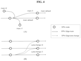
- FIG. 4 is a view for describing a feature for controlling the driving of the vehicle using a driving state of the vehicle according to one disclosure.
- FIG. 4 illustrates for describing an autonomous driving method using an SPN method according to one disclosure.
- An SPN-node indicates the location of the vehicle and, furthermore, may indicate the location to which the vehicle is movable.
- An SPN-Edge main indicates a basic driving state that is determined according to a driving route, in which the driving of the vehicle is controlled by a main driving state included in an initially set driving route when there is no new added control command.
- An SPN-Edge lane change indicates a driving state in which lane change is performed when needed, and the original route is resumed.
- an SPN-Edge main is a driving mode that is set by determining a driving route of a vehicle according to advance information acquired from map information. That is, the SPN-Edge main refers to a driving state determined according to the original route, such as performing straight driving, left-turn driving, or right-turn driving as needed.
- main, default indicates that the vehicle continues to drive straight
- main, l 1 indicates that the vehicle moves through a left turn driving on the driving route
- main, default indicates that the vehicle continue to drive straight
- the straight driving is the basic driving
- the left turn may be denoted by l 1
- the right turn may be denoted by r 1 .
- the straight driving may be determined as r 1 . That is, the basic driving state set for each road by default is determined as the driving state of the vehicle first, and when a control command to request a sub-driving state is generated according to the driving route, or when a sub-driving state needs to be inevitably performed, the driving state information may be changed.
- lane change, l 1 indicates a driving state in which the vehicle moves one lane to the left
- “lane change, l 2 ” indicates a driving state in which the vehicle moves two lanes to the left.
- the lane change driving state according to one disclosure may be selected by destination information, a control input of a user, and an autonomous driving control command according to a situation.
- the vehicle without the vehicle driving control apparatus 100 receiving the destination information is traveling in a straight driving state, which is the basic driving state, on road A, and when a lane change is required due to a vehicle accident, the vehicle driving control apparatus 100 converts the driving state of the vehicle to a lane change driving state to generate a driving control command to avoid the vehicle accident.
- FIG. 5 is a view for describing a feature for generating a driving route of a vehicle by dividing a lane in grids according to one disclosure.
- the vehicle driving control apparatus 100 of the present invention may perform autonomous driving on a vehicle using a dense path network (DPN) method together with an SPN.
- DPN is a method of setting a route in more detail than in the SPN and allows autonomous driving to be more effectively performed using a grid map that shows the location to which the vehicle may be moveable and new obstacles located around the vehicle on the basis of the current location of the vehicle.
- the DPN is set to handle an area that is subdivided at a greater degree than that of the SPN and set to control the driving of the vehicle in more detail to cope with a variety of emergencies (e.g., a vehicle parked or stopped on a shoulder or a construction section) according to movement of objects and nearby vehicles around the vehicle.
- a variety of emergencies e.g., a vehicle parked or stopped on a shoulder or a construction section
- the left drawing shows a vehicle including the vehicle driving control apparatus 100 , a vehicle 2002 parked on the shoulder, and another vehicle 2003 driving two lanes away from the vehicle including the vehicle driving control apparatus 100 to the left.
- the vehicle driving control apparatus 100 having an original driving route for continuously driving in the straight direction may recognize the parked vehicle 2002 as a new obstacle that has not been acquired from the map information. Accordingly, the vehicle driving control apparatus 100 needs to determine a new driving route for avoiding the parked vehicle 2002 , which is a new obstacle.
- a method of avoiding the parked vehicle 2002 may include a method of moving to the next lane or moving aside by half of the original lane and then returning to the original lane.
- the vehicle driving control apparatus 100 may generate a grid map indicating a location to which the vehicle is movable on the basis of the central axis of the rear wheel of the vehicle.
- the center for indicating the movable position of the vehicle is arbitrarily determined, and any part of the vehicle may be used as the central axis.
- the vehicle driving control apparatus 100 may express the location to which the vehicle is movable on the grid map as a plurality of nodes and newly generate a plurality of routes to drive while avoiding the parked vehicle 2002 by connecting the nodes. In this case, the vehicle driving control apparatus 100 may select one of a first route 2004 in which the vehicle may move two lanes to the leftmost lane, a second route 2005 in which the vehicle may move one lane leftward to the middle lane, or a third route 2006 in which the vehicle may move aside by half of the original lane and then return to the original lane.
- the vehicle driving control apparatus 100 may select a driving route most similar to the original driving route and move. For example, when the original driving route has been set to turn right at the next intersection using the rightmost lane, it is efficient to continue moving with the third route 2006 .
- a route in which the vehicle is movable at each location is generated in advance on the basis of the grid map, for example, a route for a predetermined distance from a first point is generated in advance, and the vehicle is moved according to the corresponding route, and at the end point of the corresponding route or at a location within a predetermined range of the end point, the vehicle is moved by reobtaining information about the next route (i.e., previously generated route information), thereby preventing an unnatural driving state that may occur in movement according to real-time determination.
- FIG. 6 is a view for describing an example of autonomous driving of a vehicle being performed using traffic signal information according to one disclosure.
- the vehicle driving control apparatus 100 may perform autonomous driving using a static collision map (SCM), a static tolerance map (STM), and a traffic signal map (TSM) in addition to an SPN and a DPN.
- SCM static collision map
- STM static tolerance map
- TSM traffic signal map
- the TSM uses traffic light information related to the number, status, location, shape and operation method of traffic lights installed in a predetermined region to determine the driving state and the driving speed of the vehicle using the traffic light information obtained from the current location of the vehicle.
- the TSM may further include information about whether a traffic light is present in the path of the vehicle, which position needs to be specifically recognized through an image to check the signal value when a traffic light is present, or which ID signal value needs to be viewed in vehicle to everything (V2X).
- the TSM includes information about which signal is followed by which signal to reduce the recognition error, the maximum duration of yellow light, which crosswalk pedestrian signal produces which driving signal, and the like, so that information stored in the TSM may be configured to be used as an alternative, even when a field of view is not secured with an actual required traffic light.
- the SCM determines the driving state and the driving speed of the vehicle using information about obstacles fixed to the road.
- the vehicle driving control apparatus 100 obtains coordinate information (x, y, ⁇ ) of the current position and driving direction of the vehicle, and on the basis of the coordinate information (x, y, ⁇ ), determines the chance of collision with the obstacle acquired from the map information. In this case, the chance of collision may be expressed as a probability (%).
- the vehicle driving control apparatus 100 may determine a safety event when it is determined that the vehicle may avoid collision with the obstacle, and determine a collision event when it is determined that the vehicle may not avoid collision with the obstacle.
- Such information may be stored in advance in the SCM. For example, the chance of collision with an obstacle or whether a collision with the obstacle occurs according to coordinate information (x, y, ⁇ ) of the vehicle is stored in advance so that the chance of collision or whether a collision occurs may be determined based on the previously stored information without needing to be determined in real time.
- safety and collision information according to coordination information (x, y, ⁇ ) of the vehicle may be stored in advance and utilized as advance information, thereby reducing real-time calculation.
- the collision and the safety may be calculated and stored in advance on the basis of speed-added coordinate information (x, y, ⁇ , v). For example, it is determined to be safe only considering (x, y, ⁇ ) when a fixed obstacle, such as a wall of a building, is in front of the vehicle driving at a high speed, but by adding the speed component, the situation may be determined as “collision” because collision cannot be avoided even when a brake is rapidly applied.
- Such information is stored in advance and used as advance information to determine whether a collision occurs according to the state of the vehicle.
- the collision event may be determined as a strong collision event and a weak collision event according to the collision impact of the vehicle and the obstacle, and when a collision with an obstacle is unavoidable, a driving command of the vehicle corresponding to a weak collision event with less impact generated from the collision with the obstacle is caused to be generated first to minimize the collision impact of the vehicle in autonomous drive.
- a strong collision event refers to an impact of a vehicle crashing
- a weak collision event refers to a collision of a vehicle lightly bumping or rubbing while colliding with an obstacle.
- the information related to the collision state may be determined on the basis of the shape and size of the vehicle and the obstacle, as well as the location of the vehicle and the location of the obstacle. Accordingly, when information about the same region is applied to another vehicle, information about the collision state may be updated on the basis of the shape and size of the corresponding vehicle.
- the STM is provided to evaluate the satisfaction and safety of driving during driving of the vehicle as a score and reflect the score in autonomous driving.
- the vehicle driving control apparatus obtains coordinate information (x, y, ⁇ , v) of the current position, driving direction, and driving speed of the vehicle, and on the basis of previously stored STM information, determines the autonomous driving score at the current position and the current time according to the coordinate information (x, y, ⁇ , v).
- Such various determination criteria are used to convert coordinate information (x, y, ⁇ , v) of the vehicle into scores, and the scores are stored in advance in the STM and used to immediately determine the score according to the coordinate information of the vehicle.
- the vehicle driving control apparatus 100 may determine the autonomous driving score on the basis of the safety score and the driving satisfaction score according to the coordinate information.
- the vehicle driving control apparatus 100 may determine the autonomous driving score according to a predetermined criterion, for example, on the basis of vibration data, a vehicle speed, and a driving time obtained from a sensor device installed in the vehicle.
- the autonomous driving score may be determined by comparing the most preferable advance information for driving.
- the autonomous driving score may be directly input from the user.
- the vehicle driving control apparatus 100 may change at least one of the driving route, driving direction, and driving speed of the vehicle.
- the predetermined score is a score in which autonomous driving is performable but the reliability of autonomous driving is in a range of about 60% to 70%, and thus the user's autonomous driving satisfaction is not met when the user's satisfaction is assumed to be a reliability of 80% or higher.
- the predetermined score may be determined by a user and may be determined according to a predetermined criterion.
- the vehicle driving control apparatus 100 may generate new driving route information by reflecting the surrounding environment information of the vehicle and the state of the vehicle in real time.
- the vehicle driving control apparatus 100 may output a warning message.
- the autonomous driving score less than equal to the threshold represents that the user's reliability on autonomous driving is 40% or less and determines that an error has occurred in the vehicle driving control apparatus 100 or the vehicle that performs autonomous driving.
- the vehicle driving control apparatus 100 upon receiving a user input to change to a driving assistance mode after output of the warning message, may change the autonomous driving mode of the vehicle to the driving assistance mode. That is, the autonomous driving mode is terminated, and the vehicle driving control apparatus 100 may simply perform a driving assistance operation.
- the warning message may include a visual message, an audible message, and a vibrating message and may be output in a manner predetermined by the user.
- the vehicle driving control apparatus 100 upon not receiving a user input to change to a driving assistance mode after output of the warning message, may transmit a warning message to a previously registered driver terminal and then generate a driving control command to move the vehicle to a safety area on the basis of the map information.
- the vehicle driving control apparatus 100 may not automatically terminate the autonomous driving for the safety without receiving an autonomous driving termination input from the user even though the autonomous driving needs to be terminated. Accordingly, the vehicle driving control apparatus 100 may output a warning message to the user terminal or transmit an emergency message to a previously-registered police station server, and the like.
- the vehicle driving control apparatus 100 when the vehicle driving control apparatus 100 does not receive a user input for terminating the autonomous driving, the vehicle driving control apparatus 100 allows the vehicle to be moved to a safety area included in the map information to protect the user's safety.
- the safety area may include the shoulder, a parking lot, and the like and may include areas that do not disturb movement of other vehicles and pedestrians.
- FIG. 7 is a block diagram illustrating a configuration of an apparatus for controlling driving of a vehicle using advance information according to one disclosure.
- a vehicle driving control apparatus 100 may include a processor 1100 , a communication unit 1300 , and a memory 1400 . However, all of the components shown in FIG. 7 are not essential components of the vehicle driving control apparatus 100 .
- the vehicle driving control apparatus 100 may be implemented by a larger number of components than the components illustrated in FIG. 7 , or the vehicle driving control apparatus 100 may be implemented by a smaller number of components than the components illustrated in FIG. 7 .
- the processor 1100 typically controls the overall operation of the vehicle driving control apparatus 100 .
- the processor 1100 may control the overall operation of the communication unit 1300 and other modules by executing programs stored in the memory 1400 .
- the processor 1100 may perform functions of the vehicle driving control apparatus 100 by executing programs stored in the memory 1400 .
- the processor 1100 may include at least one processor.
- the processor 1100 may include a plurality of processors or one processor in an integrated form depending on the function and role thereof.
- the processor 1100 may include at least one processor executing at least one program stored in the memory 1400 to provide a notification message.
- the processor 1100 may communicate with other parts installed in the vehicle through the communication unit 1300 .
- the processor 1100 may obtain a driving image including a plurality of frames from a camera installed in a vehicle.
- the processor 1100 may transmit a command for controlling the operation of a module installed in the vehicle to the module installed in the vehicle through the communication unit 130 on the basis of the priority of the event through the communication unit 1300 .
- the processor 1100 may analyze the driving image to detect an object included in the plurality of frames. In one embodiment, the processor 1100 may recognize location information of an object for each of the plurality of frames using coordinate information.
- the vehicle driving control apparatus 100 may further include a sensing unit (not shown), and may acquire sensing information of the vehicle during drive from the sensing unit for detection of an event.
- the sensing unit includes a geomagnetic sensor, an acceleration sensor, a temperature/humidity sensor, an infrared sensor, a gyroscope sensor, a position sensor (for example, global positioning system: GPS), a barometric pressure sensor, a proximity sensor, and an RGB sensor but is not limited thereto. Since the function of each sensor is intuitively inferred by those skilled in the art from the name of the sensor, detailed descriptions thereof will be omitted.
- the communication unit 1300 may include one or more components that allow the vehicle driving control apparatus 100 to communicate with another electronic device (not shown) and the server 2000 .
- Another electronic device (not shown) may be a computing device or a sensing device but is not limited thereto.
- another electronic device for example, may be a module included in the vehicle, such as the vehicle driving control apparatus 100 .
- the communication unit 1300 may include a short-range wireless communication unit, a mobile communication unit, and a broadcast receiving unit.
- the short-range wireless communication unit includes a Bluetooth communication unit, a Bluetooth low energy (BLE) communication unit, a near field communication unit, a Wireless Local Area Network (WLAN, Wi-Fi) communication unit, a ZigBee communication unit, an infrared data association (IrDA) communication unit, a Wi-Fi Direct (WFD) communication unit, a ultra-wideband (UWB) communication unit, an Ant+ communication unit, and the like but is not limited thereto.
- BLE Bluetooth low energy
- WLAN Wireless Local Area Network
- Wi-Fi Wireless Local Area Network
- ZigBee ZigBee communication unit
- IrDA infrared data association
- WFD Wi-Fi Direct
- UWB ultra-wideband
- the mobile communication unit transmits and receives a radio signal to and from at least one of a base station, an external terminal, and a server on a mobile communication network.
- the radio signal may include various types of data according to transmission and reception of a voice call signal, a video call signal, or a text/multimedia message.
- the broadcast receiving unit receives a broadcast signal and/or broadcast-related information from the outside through a broadcast channel.
- the broadcast channel may include a satellite channel and a terrestrial channel.
- the vehicle driving control apparatus 100 may not include the broadcast receiving unit 1530 .
- the memory 1400 may store a program for processing and control of the processor 1100 and may store data input to or output from the vehicle driving control apparatus 100 .
- the memory 1400 may include at least one type of storage medium from among a flash memory type memory, a hard disk type memory, a multimedia card micro type memory, a card type memory (for example, SD or XD memory, etc.), a random access memory (RAM), a static RAM (SRAM), a read-only memory (ROM), an electrically erasable programmable ROM (EEPROM), a programmable ROM (PROM), a magnetic memory, a magnetic disk, and an optical disk.
- a flash memory type memory for example, a hard disk type memory, a multimedia card micro type memory, a card type memory (for example, SD or XD memory, etc.), a random access memory (RAM), a static RAM (SRAM), a read-only memory (ROM), an electrically erasable programmable ROM (EEPROM), a programmable ROM (PROM), a magnetic memory, a magnetic disk, and an optical disk.
- a flash memory type memory for example, SD or XD memory, etc
- Programs stored in the memory 1400 may be classified into a plurality of modules according to the functions thereof, for example, into a user interface (UI) module, a touch screen module, a notification module, and the like.
- UI user interface
- touch screen module a touch screen module
- notification module a notification module
- Some embodiments can be embodied in the form of a recording medium that contains therein computer executable instructions, such as a program module that is executed by computers.
- the computer readable medium can be any available medium that can be accessed by computers and includes all of volatile and nonvolatile media and removable and non-removable media.
- the computer readable medium may include all of computer storage media.
- the computer storage media include all of volatile and nonvolatile media and removable and non-removable media, which are realized by any methods or technologies for storing information, such as computer readable instructions, data structures, program modules or other data.
- part refers to a hardware component such as a processor or a circuit and/or a software component to be executed by a hardware component, such as a processor.
- the components of the present invention may be implemented as a program (or an application) to be executed in combination with a hardware computer and stored in a medium.
- the components of the present invention may be implemented in software programming or software components, and similarly, embodiments may be implemented in programming or scripting languages, such as C, C++, Java, assembler, etc., including various algorithms implemented in a combination of data structures, processes, routines or other programming components. Functional aspects may be implemented with algorithms running on one or more processors.
- a route is generated using advance information, such as lane information, road attribute information, and speed limit information so that various driving routes can be generated in a short time.
- driving is performed at an optimum speed by reflecting the user experience, such as riding comfort information of the user so that the user's satisfaction can be increased.
- a starting position is connected to a target position through nodes to generate at least one driving route in advance, and the optimal driving route is selected by reflecting obstacle information, road traffic information, and the like so that the driving efficiency can be increased.
Abstract
Description
-
- (Patent Document 1) Korean Laid-open Patent Publication No. 10-2018-0094823 (Aug. 24, 2018)
- (Patent Document 2) Korean Registered Patent No. 10-1695557 (Jan. 5, 2017)
Claims (12)
Applications Claiming Priority (2)
| Application Number | Priority Date | Filing Date | Title |
|---|---|---|---|
| KR1020190056859A KR102061750B1 (en) | 2019-05-15 | 2019-05-15 | Method and apparatus for controlling a vehicle’s driving operation using advance information |
| KR10-2019-0056859 | 2019-05-15 |
Publications (2)
| Publication Number | Publication Date |
|---|---|
| US20200361489A1 US20200361489A1 (en) | 2020-11-19 |
| US11958504B2 true US11958504B2 (en) | 2024-04-16 |
Family
ID=69155641
Family Applications (1)
| Application Number | Title | Priority Date | Filing Date |
|---|---|---|---|
| US16/875,429 Active US11958504B2 (en) | 2019-05-15 | 2020-05-15 | Method and apparatus for controlling a vehicle's driving operation using advance information |
Country Status (2)
| Country | Link |
|---|---|
| US (1) | US11958504B2 (en) |
| KR (1) | KR102061750B1 (en) |
Families Citing this family (27)
| Publication number | Priority date | Publication date | Assignee | Title |
|---|---|---|---|---|
| US11718300B2 (en) * | 2019-02-27 | 2023-08-08 | Zf Automotive Germany Gmbh | Method and control unit for a system for controlling a motor vehicle |
| US11599117B2 (en) * | 2020-02-20 | 2023-03-07 | Steering Solutions Ip Holding Corporation | Systems and methods for obstacle proximity detection |
| CN111653113B (en) * | 2020-04-20 | 2022-09-27 | 浙江吉利汽车研究院有限公司 | Method, device, terminal and storage medium for determining local path of vehicle |
| EP3905106A1 (en) | 2020-04-27 | 2021-11-03 | Aptiv Technologies Limited | Method for determining a drivable area |
| EP3905105A1 (en) * | 2020-04-27 | 2021-11-03 | Aptiv Technologies Limited | Method for determining a collision free space |
| JP7449770B2 (en) * | 2020-04-28 | 2024-03-14 | 三菱重工業株式会社 | Terminal, control system, control method and program |
| KR102443401B1 (en) * | 2020-06-29 | 2022-09-15 | 주식회사 라이드플럭스 | Method, apparatus and computer program for generating road network data to automatic driving vehicle |
| CN111845720B (en) * | 2020-06-30 | 2022-06-14 | 阿波罗智能技术(北京)有限公司 | Method and apparatus for controlling vehicle, electronic device, and storage medium |
| KR102196804B1 (en) * | 2020-07-20 | 2020-12-30 | 김성규 | Automobile driving system to implement fuel saving based on Internet-of-Things and Artificial Intelligence |
| US11884265B1 (en) * | 2020-11-02 | 2024-01-30 | Nissan Motor Co., Ltd. | Parking assistance method and parking assistance device |
| CN112660122A (en) * | 2020-12-29 | 2021-04-16 | 山东华宇工学院 | Active safe driving early warning method based on 5G low delay and Beidou navigation |
| FR3120041B1 (en) * | 2021-02-23 | 2023-01-06 | Psa Automobiles Sa | METHOD AND DEVICE FOR DETERMINING A DECELERATION SETPOINT FOR AN AUTONOMOUS VEHICLE |
| KR20220163560A (en) * | 2021-06-02 | 2022-12-12 | 현대자동차주식회사 | System for controlling driving speed of vehicle and method thereof |
| CN113232658B (en) * | 2021-06-28 | 2022-06-28 | 驭势(上海)汽车科技有限公司 | Vehicle positioning method and device, electronic equipment and storage medium |
| WO2023279346A1 (en) * | 2021-07-08 | 2023-01-12 | Nec Corporation | Method, device and computer storage medium of communication |
| KR102656694B1 (en) * | 2021-09-28 | 2024-04-12 | 포티투닷 주식회사 | Method, apparatus, server and medium for determining a moving route of lane |
| CN113895458B (en) * | 2021-10-26 | 2023-06-30 | 上海集度汽车有限公司 | Vehicle driving behavior management method and device, vehicle and storage medium |
| CN113954838B (en) * | 2021-11-24 | 2023-04-07 | 上海安亭地平线智能交通技术有限公司 | Vehicle lane change control method and device, electronic device and storage medium |
| CN114132317B (en) * | 2021-11-30 | 2023-05-23 | 重庆长安新能源汽车科技有限公司 | Intelligent curve side driving control method, system, vehicle and storage medium |
| CN114407922A (en) * | 2022-01-18 | 2022-04-29 | 上汽通用五菱汽车股份有限公司 | Intelligent vehicle automatic driving method, device, equipment and readable storage medium |
| CN116931849A (en) * | 2022-03-29 | 2023-10-24 | 华为技术有限公司 | Display method and electronic device |
| CN114724366B (en) * | 2022-03-29 | 2023-06-20 | 北京万集科技股份有限公司 | Driving assistance method, device, equipment and storage medium |
| CN114789723B (en) * | 2022-06-10 | 2022-09-09 | 小米汽车科技有限公司 | Vehicle running control method and device, vehicle, storage medium and chip |
| US20230415741A1 (en) * | 2022-06-22 | 2023-12-28 | Aptiv Technologies Limited | Target of Interest Selection on Roadway Ramps |
| CN115240448B (en) * | 2022-09-21 | 2022-12-09 | 北京科技大学 | Road corner early warning system |
| CN116086477B (en) * | 2023-01-30 | 2024-02-20 | 禾多科技(北京)有限公司 | Local path information generation method, device, equipment and computer readable medium |
| KR102643539B1 (en) * | 2023-09-25 | 2024-03-06 | 주식회사 라이드플럭스 | Method, computing device and computer program for controlling autonomous vehicle speed capable of responding to uncomfortable region |
Citations (21)
| Publication number | Priority date | Publication date | Assignee | Title |
|---|---|---|---|---|
| KR20150110713A (en) | 2013-01-25 | 2015-10-02 | 바브코 게엠베하 | Method for determining a triggering criterion for braking and an emergency braking system for a vehicle |
| US9517771B2 (en) * | 2013-11-22 | 2016-12-13 | Ford Global Technologies, Llc | Autonomous vehicle modes |
| KR101695557B1 (en) | 2015-07-17 | 2017-01-24 | 고려대학교 산학협력단 | Automated guided vehicle system based on autonomous mobile technique and a method for controlling the same |
| US9558408B2 (en) * | 2013-10-15 | 2017-01-31 | Ford Global Technologies, Llc | Traffic signal prediction |
| KR20170015238A (en) | 2015-07-30 | 2017-02-08 | 삼성전자주식회사 | Autonomous vehicle and method for controlling the autonomous vehicle |
| KR20170077317A (en) | 2015-12-28 | 2017-07-06 | 자동차부품연구원 | Apparatus for controlling autonomous emergency braking system and method thereof |
| JP2017211758A (en) | 2016-05-24 | 2017-11-30 | シャープ株式会社 | Autonomous travel device |
| KR20170133149A (en) | 2016-05-25 | 2017-12-05 | 주식회사 만도 | Autonomy driving method and system based on road learning |
| US9946260B2 (en) * | 2015-02-10 | 2018-04-17 | Mobileye Vision Technologies Ltd. | Sparse map autonomous vehicle navigation |
| JP2018077087A (en) | 2016-11-08 | 2018-05-17 | 本田技研工業株式会社 | Information display device, information display method, and information display program |
| KR20180094823A (en) | 2018-08-14 | 2018-08-24 | 현대자동차주식회사 | Vehicle control apparatus and method for driving safety |
| JP2018136966A (en) | 2012-09-28 | 2018-08-30 | パナソニックIpマネジメント株式会社 | Notification device and vehicle utilizing the same |
| US20180292822A1 (en) * | 2017-04-11 | 2018-10-11 | Toyota Jidosha Kabushiki Kaisha | Automatic driving system |
| US20180356830A1 (en) * | 2017-06-12 | 2018-12-13 | GM Global Technology Operations LLC | Personalized autonomous vehicle ride characteristics |
| JP2019043495A (en) | 2017-09-07 | 2019-03-22 | 株式会社デンソー | Device, system and method for adjusting automatic operation |
| US10417910B2 (en) * | 2014-03-03 | 2019-09-17 | Inrix, Inc. | Driving profiles for autonomous vehicles |
| US20190322276A1 (en) * | 2018-04-19 | 2019-10-24 | Volvo Car Corporation | Method and system for vehicle curve speed restriction |
| US10679497B1 (en) * | 2016-01-22 | 2020-06-09 | State Farm Mutual Automobile Insurance Company | Autonomous vehicle application |
| US10809731B2 (en) * | 2017-07-13 | 2020-10-20 | Beijing Voyager Technology Co., Ltd. | Systems and methods for trajectory determination |
| US20210237769A1 (en) * | 2018-05-31 | 2021-08-05 | Nissan North America, Inc. | Trajectory Planning |
| US20220011127A1 (en) * | 2016-11-26 | 2022-01-13 | Thinkware Corporation | Device, method, computer program, and computer readable-recording medium for route guidance |
-
2019
- 2019-05-15 KR KR1020190056859A patent/KR102061750B1/en active IP Right Grant
-
2020
- 2020-05-15 US US16/875,429 patent/US11958504B2/en active Active
Patent Citations (21)
| Publication number | Priority date | Publication date | Assignee | Title |
|---|---|---|---|---|
| JP2018136966A (en) | 2012-09-28 | 2018-08-30 | パナソニックIpマネジメント株式会社 | Notification device and vehicle utilizing the same |
| KR20150110713A (en) | 2013-01-25 | 2015-10-02 | 바브코 게엠베하 | Method for determining a triggering criterion for braking and an emergency braking system for a vehicle |
| US9558408B2 (en) * | 2013-10-15 | 2017-01-31 | Ford Global Technologies, Llc | Traffic signal prediction |
| US9517771B2 (en) * | 2013-11-22 | 2016-12-13 | Ford Global Technologies, Llc | Autonomous vehicle modes |
| US10417910B2 (en) * | 2014-03-03 | 2019-09-17 | Inrix, Inc. | Driving profiles for autonomous vehicles |
| US9946260B2 (en) * | 2015-02-10 | 2018-04-17 | Mobileye Vision Technologies Ltd. | Sparse map autonomous vehicle navigation |
| KR101695557B1 (en) | 2015-07-17 | 2017-01-24 | 고려대학교 산학협력단 | Automated guided vehicle system based on autonomous mobile technique and a method for controlling the same |
| KR20170015238A (en) | 2015-07-30 | 2017-02-08 | 삼성전자주식회사 | Autonomous vehicle and method for controlling the autonomous vehicle |
| KR20170077317A (en) | 2015-12-28 | 2017-07-06 | 자동차부품연구원 | Apparatus for controlling autonomous emergency braking system and method thereof |
| US10679497B1 (en) * | 2016-01-22 | 2020-06-09 | State Farm Mutual Automobile Insurance Company | Autonomous vehicle application |
| JP2017211758A (en) | 2016-05-24 | 2017-11-30 | シャープ株式会社 | Autonomous travel device |
| KR20170133149A (en) | 2016-05-25 | 2017-12-05 | 주식회사 만도 | Autonomy driving method and system based on road learning |
| JP2018077087A (en) | 2016-11-08 | 2018-05-17 | 本田技研工業株式会社 | Information display device, information display method, and information display program |
| US20220011127A1 (en) * | 2016-11-26 | 2022-01-13 | Thinkware Corporation | Device, method, computer program, and computer readable-recording medium for route guidance |
| US20180292822A1 (en) * | 2017-04-11 | 2018-10-11 | Toyota Jidosha Kabushiki Kaisha | Automatic driving system |
| US20180356830A1 (en) * | 2017-06-12 | 2018-12-13 | GM Global Technology Operations LLC | Personalized autonomous vehicle ride characteristics |
| US10809731B2 (en) * | 2017-07-13 | 2020-10-20 | Beijing Voyager Technology Co., Ltd. | Systems and methods for trajectory determination |
| JP2019043495A (en) | 2017-09-07 | 2019-03-22 | 株式会社デンソー | Device, system and method for adjusting automatic operation |
| US20190322276A1 (en) * | 2018-04-19 | 2019-10-24 | Volvo Car Corporation | Method and system for vehicle curve speed restriction |
| US20210237769A1 (en) * | 2018-05-31 | 2021-08-05 | Nissan North America, Inc. | Trajectory Planning |
| KR20180094823A (en) | 2018-08-14 | 2018-08-24 | 현대자동차주식회사 | Vehicle control apparatus and method for driving safety |
Also Published As
| Publication number | Publication date |
|---|---|
| US20200361489A1 (en) | 2020-11-19 |
| KR102061750B1 (en) | 2020-01-03 |
Similar Documents
| Publication | Publication Date | Title |
|---|---|---|
| US11958504B2 (en) | Method and apparatus for controlling a vehicle's driving operation using advance information | |
| US11126877B2 (en) | Predicting vehicle movements based on driver body language | |
| US11619998B2 (en) | Communication between autonomous vehicle and external observers | |
| US11619940B2 (en) | Operating an autonomous vehicle according to road user reaction modeling with occlusions | |
| US11860625B2 (en) | System and method for updating vehicle operation based on remote intervention | |
| US9558408B2 (en) | Traffic signal prediction | |
| US20200211370A1 (en) | Map editing using vehicle-provided data | |
| US9373255B2 (en) | Method and system for producing an up-to-date situation depiction | |
| US20200209845A1 (en) | System and method for remote intervention of vehicles | |
| KR20190067233A (en) | Dynamic routing for autonomous vehicles | |
| US20150106010A1 (en) | Aerial data for vehicle navigation | |
| JP6489003B2 (en) | Route search device and vehicle automatic driving device | |
| US11315421B2 (en) | Systems and methods for providing driving recommendations | |
| KR102483716B1 (en) | Method and apparatus for controlling a vehicle’s driving operation using advance information | |
| US11866037B2 (en) | Behavior-based vehicle alerts | |
| US11945433B1 (en) | Risk mitigation in speed planning | |
| JPWO2020009060A1 (en) | Information processing equipment and information processing methods, computer programs, and mobile equipment | |
| US20200211379A1 (en) | Roundabout assist | |
| CN113167592A (en) | Information processing apparatus, information processing method, and information processing program | |
| JP7315101B2 (en) | Obstacle information management device, obstacle information management method, vehicle device | |
| US20220281482A1 (en) | Vehicle control device, vehicle control method, and computer-readable storage medium storing program | |
| WO2023187718A1 (en) | Adaptive advanced driver-assistance system (adas) |
Legal Events
| Date | Code | Title | Description |
|---|---|---|---|
| AS | Assignment |
Owner name: RIDEFLUX INC., KOREA, REPUBLIC OF Free format text: ASSIGNMENT OF ASSIGNORS INTEREST;ASSIGNORS:PARK, JUNGHEE;YUN, HO;KIM, SOHYUN;AND OTHERS;REEL/FRAME:052675/0132 Effective date: 20200507 |
|
| FEPP | Fee payment procedure |
Free format text: ENTITY STATUS SET TO UNDISCOUNTED (ORIGINAL EVENT CODE: BIG.); ENTITY STATUS OF PATENT OWNER: SMALL ENTITY |
|
| FEPP | Fee payment procedure |
Free format text: ENTITY STATUS SET TO SMALL (ORIGINAL EVENT CODE: SMAL); ENTITY STATUS OF PATENT OWNER: SMALL ENTITY Free format text: ENTITY STATUS SET TO MICRO (ORIGINAL EVENT CODE: MICR); ENTITY STATUS OF PATENT OWNER: SMALL ENTITY |
|
| STPP | Information on status: patent application and granting procedure in general |
Free format text: DOCKETED NEW CASE - READY FOR EXAMINATION |
|
| FEPP | Fee payment procedure |
Free format text: ENTITY STATUS SET TO SMALL (ORIGINAL EVENT CODE: SMAL); ENTITY STATUS OF PATENT OWNER: SMALL ENTITY |
|
| STPP | Information on status: patent application and granting procedure in general |
Free format text: NON FINAL ACTION MAILED |
|
| STPP | Information on status: patent application and granting procedure in general |
Free format text: RESPONSE TO NON-FINAL OFFICE ACTION ENTERED AND FORWARDED TO EXAMINER |
|
| STPP | Information on status: patent application and granting procedure in general |
Free format text: FINAL REJECTION MAILED |
|
| STPP | Information on status: patent application and granting procedure in general |
Free format text: RESPONSE AFTER FINAL ACTION FORWARDED TO EXAMINER |
|
| STPP | Information on status: patent application and granting procedure in general |
Free format text: ADVISORY ACTION MAILED |
|
| STPP | Information on status: patent application and granting procedure in general |
Free format text: DOCKETED NEW CASE - READY FOR EXAMINATION |
|
| STPP | Information on status: patent application and granting procedure in general |
Free format text: RESPONSE TO NON-FINAL OFFICE ACTION ENTERED AND FORWARDED TO EXAMINER |
|
| STPP | Information on status: patent application and granting procedure in general |
Free format text: FINAL REJECTION MAILED |
|
| STPP | Information on status: patent application and granting procedure in general |
Free format text: DOCKETED NEW CASE - READY FOR EXAMINATION |
|
| STPP | Information on status: patent application and granting procedure in general |
Free format text: NOTICE OF ALLOWANCE MAILED -- APPLICATION RECEIVED IN OFFICE OF PUBLICATIONS |
|
| STPP | Information on status: patent application and granting procedure in general |
Free format text: PUBLICATIONS -- ISSUE FEE PAYMENT VERIFIED |
|
| STCF | Information on status: patent grant |
Free format text: PATENTED CASE |