US11834866B2 - Flexible coupling for electronic deadbolt systems - Google Patents
Flexible coupling for electronic deadbolt systems Download PDFInfo
- Publication number
- US11834866B2 US11834866B2 US16/664,144 US201916664144A US11834866B2 US 11834866 B2 US11834866 B2 US 11834866B2 US 201916664144 A US201916664144 A US 201916664144A US 11834866 B2 US11834866 B2 US 11834866B2
- Authority
- US
- United States
- Prior art keywords
- drive
- driven
- hub
- deadbolt
- leadscrew
- Prior art date
- Legal status (The legal status is an assumption and is not a legal conclusion. Google has not performed a legal analysis and makes no representation as to the accuracy of the status listed.)
- Active, expires
Links
- 230000008878 coupling Effects 0.000 title claims abstract description 45
- 238000010168 coupling process Methods 0.000 title claims abstract description 45
- 238000005859 coupling reaction Methods 0.000 title claims abstract description 45
- 239000000463 material Substances 0.000 description 9
- 238000005516 engineering process Methods 0.000 description 8
- 230000004323 axial length Effects 0.000 description 4
- 238000004891 communication Methods 0.000 description 3
- 238000004519 manufacturing process Methods 0.000 description 3
- 238000007906 compression Methods 0.000 description 2
- 238000012986 modification Methods 0.000 description 2
- 230000004048 modification Effects 0.000 description 2
- 238000012544 monitoring process Methods 0.000 description 2
- 230000035939 shock Effects 0.000 description 2
- 229910001369 Brass Inorganic materials 0.000 description 1
- 239000004698 Polyethylene Substances 0.000 description 1
- 229910000831 Steel Inorganic materials 0.000 description 1
- HCHKCACWOHOZIP-UHFFFAOYSA-N Zinc Chemical compound [Zn] HCHKCACWOHOZIP-UHFFFAOYSA-N 0.000 description 1
- 238000010521 absorption reaction Methods 0.000 description 1
- XAGFODPZIPBFFR-UHFFFAOYSA-N aluminium Chemical compound [Al] XAGFODPZIPBFFR-UHFFFAOYSA-N 0.000 description 1
- 229910052782 aluminium Inorganic materials 0.000 description 1
- 239000010951 brass Substances 0.000 description 1
- 230000006835 compression Effects 0.000 description 1
- 230000007613 environmental effect Effects 0.000 description 1
- 238000000034 method Methods 0.000 description 1
- 239000002991 molded plastic Substances 0.000 description 1
- 229920001084 poly(chloroprene) Polymers 0.000 description 1
- -1 polyethylene Polymers 0.000 description 1
- 229920000573 polyethylene Polymers 0.000 description 1
- 230000000717 retained effect Effects 0.000 description 1
- 239000002210 silicon-based material Substances 0.000 description 1
- 229910001220 stainless steel Inorganic materials 0.000 description 1
- 239000010935 stainless steel Substances 0.000 description 1
- 239000010959 steel Substances 0.000 description 1
- 239000013589 supplement Substances 0.000 description 1
- 239000011800 void material Substances 0.000 description 1
- 239000011701 zinc Substances 0.000 description 1
- 229910052725 zinc Inorganic materials 0.000 description 1
Images


Classifications
-
- E—FIXED CONSTRUCTIONS
- E05—LOCKS; KEYS; WINDOW OR DOOR FITTINGS; SAFES
- E05B—LOCKS; ACCESSORIES THEREFOR; HANDCUFFS
- E05B63/00—Locks or fastenings with special structural characteristics
- E05B63/14—Arrangement of several locks or locks with several bolts, e.g. arranged one behind the other
- E05B63/143—Arrangement of several locks, e.g. in parallel or series, on one or more wings
-
- E—FIXED CONSTRUCTIONS
- E05—LOCKS; KEYS; WINDOW OR DOOR FITTINGS; SAFES
- E05B—LOCKS; ACCESSORIES THEREFOR; HANDCUFFS
- E05B47/00—Operating or controlling locks or other fastening devices by electric or magnetic means
- E05B47/0001—Operating or controlling locks or other fastening devices by electric or magnetic means with electric actuators; Constructional features thereof
-
- E—FIXED CONSTRUCTIONS
- E05—LOCKS; KEYS; WINDOW OR DOOR FITTINGS; SAFES
- E05B—LOCKS; ACCESSORIES THEREFOR; HANDCUFFS
- E05B47/00—Operating or controlling locks or other fastening devices by electric or magnetic means
- E05B47/02—Movement of the bolt by electromagnetic means; Adaptation of locks, latches, or parts thereof, for movement of the bolt by electromagnetic means
- E05B47/026—Movement of the bolt by electromagnetic means; Adaptation of locks, latches, or parts thereof, for movement of the bolt by electromagnetic means the bolt moving rectilinearly
-
- E—FIXED CONSTRUCTIONS
- E05—LOCKS; KEYS; WINDOW OR DOOR FITTINGS; SAFES
- E05B—LOCKS; ACCESSORIES THEREFOR; HANDCUFFS
- E05B63/00—Locks or fastenings with special structural characteristics
- E05B63/0017—Locks with sliding bolt without provision for latching
-
- E—FIXED CONSTRUCTIONS
- E05—LOCKS; KEYS; WINDOW OR DOOR FITTINGS; SAFES
- E05B—LOCKS; ACCESSORIES THEREFOR; HANDCUFFS
- E05B47/00—Operating or controlling locks or other fastening devices by electric or magnetic means
- E05B47/0001—Operating or controlling locks or other fastening devices by electric or magnetic means with electric actuators; Constructional features thereof
- E05B2047/0014—Constructional features of actuators or power transmissions therefor
- E05B2047/0018—Details of actuator transmissions
- E05B2047/002—Geared transmissions
-
- E—FIXED CONSTRUCTIONS
- E05—LOCKS; KEYS; WINDOW OR DOOR FITTINGS; SAFES
- E05B—LOCKS; ACCESSORIES THEREFOR; HANDCUFFS
- E05B47/00—Operating or controlling locks or other fastening devices by electric or magnetic means
- E05B47/0001—Operating or controlling locks or other fastening devices by electric or magnetic means with electric actuators; Constructional features thereof
- E05B2047/0014—Constructional features of actuators or power transmissions therefor
- E05B2047/0018—Details of actuator transmissions
- E05B2047/0023—Nuts or nut-like elements moving along a driven threaded axle
-
- E—FIXED CONSTRUCTIONS
- E05—LOCKS; KEYS; WINDOW OR DOOR FITTINGS; SAFES
- E05B—LOCKS; ACCESSORIES THEREFOR; HANDCUFFS
- E05B47/00—Operating or controlling locks or other fastening devices by electric or magnetic means
- E05B47/0001—Operating or controlling locks or other fastening devices by electric or magnetic means with electric actuators; Constructional features thereof
- E05B2047/0014—Constructional features of actuators or power transmissions therefor
- E05B2047/0018—Details of actuator transmissions
- E05B2047/0026—Clutches, couplings or braking arrangements
- E05B2047/0031—Clutches, couplings or braking arrangements of the elastic type
-
- E—FIXED CONSTRUCTIONS
- E05—LOCKS; KEYS; WINDOW OR DOOR FITTINGS; SAFES
- E05B—LOCKS; ACCESSORIES THEREFOR; HANDCUFFS
- E05B47/00—Operating or controlling locks or other fastening devices by electric or magnetic means
- E05B2047/0094—Mechanical aspects of remotely controlled locks
-
- E—FIXED CONSTRUCTIONS
- E05—LOCKS; KEYS; WINDOW OR DOOR FITTINGS; SAFES
- E05B—LOCKS; ACCESSORIES THEREFOR; HANDCUFFS
- E05B47/00—Operating or controlling locks or other fastening devices by electric or magnetic means
- E05B47/0001—Operating or controlling locks or other fastening devices by electric or magnetic means with electric actuators; Constructional features thereof
- E05B47/0012—Operating or controlling locks or other fastening devices by electric or magnetic means with electric actuators; Constructional features thereof with rotary electromotors
-
- E—FIXED CONSTRUCTIONS
- E05—LOCKS; KEYS; WINDOW OR DOOR FITTINGS; SAFES
- E05B—LOCKS; ACCESSORIES THEREFOR; HANDCUFFS
- E05B63/00—Locks or fastenings with special structural characteristics
- E05B63/0052—Locks mounted on the "frame" cooperating with means on the "wing"
Definitions
- Deadbolts are typically operated by a user (e.g., with a key on an outside of the door or a thumbturn on the inside of the door) to secure a door or a window against unwanted intrusions.
- a user e.g., with a key on an outside of the door or a thumbturn on the inside of the door
- At least some known deadbolts are motorized, but it can often be difficult to install these systems within doors, as well as deliver reliable power. Additionally, during operation of at least some motorized deadbolts, the drive systems may undesirably experience increased loading at the end of the stroke length of the deadbolt.
- the technology relates to an electronic deadbolt including: a housing; a deadbolt configured to extend or retract from the housing; and a drive system disposed at least partially within the housing, wherein the drive system includes: an electric motor; a leadscrew coupled between the electric motor and the deadbolt, wherein the leadscrew is rotatable about a longitudinal axis so as to dive movement of the deadbolt; and a flexible coupling disposed between the electric motor and the leadscrew.
- the flexible coupling includes: a drive hub including at least one drive lug; a driven hub including at least one driven lug; and a flexible collar disposed at least partially between the at least one drive lug and the at least one driven lug.
- the at least one drive lug and the at least one driven lug extend radially relative to the longitudinal axis.
- the leadscrew has a first end and an opposite second end, and the first end is threadingly coupled to the deadbolt and the second end includes the driven hub.
- the driven hub is integral with the second end of the leadscrew.
- the driven hub includes a bore sized and shaped to at least partially receive the drive hub and the flexible collar.
- the drive hub includes a pair of drive lugs of the at least one drive lug spaced approximately 180° apart and the driven hub includes a pair of driven lugs of the at least one driven lug spaced approximately 180° apart.
- the flexible collar includes four legs, each disposed between a drive lug of the pair of drive lugs and a driven lug of the pair of driven lugs.
- the housing defines the longitudinal axis.
- the flexible coupling is configured to absorb torsional loads generated by the movement of the deadbolt.
- the technology in another aspect, relates to a drive system for an electronic lock device including a locking element and a housing, wherein the drive system includes: an electric motor; a rotatable shaft coupled to the electric motor and rotatable about a longitudinal axis; a drive hub coupled to the rotatable shaft; a driven hub rotationally engaged with the drive hub; a leadscrew coupled to the driven hub, wherein upon rotation of the leadscrew the locking element extends or retracts from the housing; and a flexible collar disposed at least partially between the drive hub and the driven hub, wherein the flexible collar is configured to absorb torsional loads between the drive hub and the driven hub.
- the electric motor includes at least one gear.
- the drive hub is at least partially received within the driven hub.
- the driven hub is integral with the leadscrew.
- the drive hub includes a plurality of drive lugs and the driven hub includes a plurality of driven lugs
- the flexible collar includes a plurality of legs and each leg is disposed between one drive lug of the plurality of drive lugs and one driven lug of the plurality of driven lugs. In an example, each leg is in direct contact with the drive lug and the driven lug.
- the plurality of legs are connected to one another.
- the electric motor, the rotatable shaft, and the leadscrew are axially aligned along the longitudinal axis.
- the technology in another aspect, relates to an electronic lock device for a door or a window including: a housing; a locking element; and a drive system disposed at least partially within the housing and configured to extend or retract the locking element from the housing, wherein the drive system includes: an electric motor including one or more gears driving a rotatable shaft about a longitudinal axis; a leadscrew coupled between the electric motor and the locking element, wherein the leadscrew is rotatable about the longitudinal axis so as to drive movement of the locking element; and a flexible coupling disposed between the electric motor and the leadscrew, wherein the flexible coupling includes: a drive hub including a pair of drive lugs coupled to the rotatable shaft; a driven hub including a pair of driven lugs coupled to the leadscrew; and a flexible collar disposed at least partially between the drive hub and the driven hub.
- the flexible coupling is axially aligned with the leadscrew and the electric motor along the longitudinal axis.
- FIG. 1 depicts a schematic view of an electronic door lock system.
- FIG. 2 is a perspective view of an exemplary electronic lock device.
- FIG. 3 is a perspective view of an exemplary drive system.
- FIG. 4 is an exploded perspective view of the drive system shown in FIG. 3 .
- FIG. 5 is an exploded side view of an exemplary flexible coupling.
- FIG. 6 is a partial end view of the flexible coupling shown in FIG. 5 .
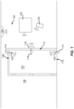
- FIG. 1 depicts a schematic view of one example of a multi-point electric door lock system 100 .
- the system 100 includes two electronic deadbolts 102 installed in a door panel 104 , for example, so as to extend into a portion of a frame 106 such as a head and/or a sill thereof.
- the electronic deadbolts 102 may be installed within a locking edge of the door panel 104 so as to extend into a vertical portion of the frame 106 between the head and the sill.
- the electronic deadbolts 102 may be installed in the frame 106 so as to extend into the door 104 .
- the placement and number of electronic deadbolts 102 may be altered as required or desired for a particular application, for example, in pivoting doors, the electronic deadbolts may be disposed so as to extend from a head 108 , a sill 110 , or a locking edge 112 (e.g., vertical edge) of the door 104 .
- the door panel 104 is a pivoting door; however, the electronic deadbolts described herein can be utilized in entry doors, sliding doors, pivoting patio doors, and any other door as required or desired.
- the electronic deadbolts 102 In sliding patio doors, the electronic deadbolts 102 have linearly extending locking elements that may extend from the head 108 or the sill 110 of the sliding door. If utilized on the locking edge 112 of a sliding door, the electronic deadbolt 102 would require a hook-shaped locking element that would hook about a keeper so as to prevent retraction of the door. Additionally or alternatively, the electronic deadbolts may be used in windows or any other panel type structure that can be locked with an extendable and/or retractable locking element.
- each electronic deadbolt 102 is positioned to as to extend into a keeper 114 .
- the keepers 114 may be standard keepers or electronic keepers as described in U.S. patent application Ser. No. 15/239,714, filed Aug. 17, 2016, entitled “Locking System Having an Electronic Keeper,” and the disclosure of which is herein incorporated by reference in its entirety.
- the system 100 also includes an electronic keeper 116 configured to receive a standard (e.g., manually-actuated) deadbolt 118 , as typically available on an entry or patio door.
- the electronic keeper 116 detects a position of the deadbolt 118 therein.
- a signal may be sent to the remotely located electronic deadbolts 102 , thus causing actuation thereof.
- the door 104 is now locked at multiple points. Unlocking of the manual deadbolt 118 is detected by the electronic keeper 116 (that is, the keeper 116 no longer detects the presence of the deadbolt 118 therein) and a signal is sent to the remote electronic deadbolts 102 causing retraction thereof, thus allowing the door 104 to be opened.
- the electronic deadbolts described herein may be utilized to create a robust multi-point locking system for a door and to improve the security thereof.
- the system 100 may include a controller/monitoring system, which may be a remote panel 120 , which may be used to extend or retract the electronic deadbolts 102 , or which may be used for communication between the various electronic keepers 114 and deadbolts 102 .
- a controller/monitoring system which may be a remote panel 120 , which may be used to extend or retract the electronic deadbolts 102 , or which may be used for communication between the various electronic keepers 114 and deadbolts 102 .
- an application on a remote computer or smartphone 122 may take the place of, or supplement, the remote panel 120 .
- the electronic deadbolts 102 may be locked or unlocked remotely, thus providing multi-point locking ability without the requirement for manual actuation of the deadbolt 118 .
- any or all of the components may communicate either directly or indirectly with a home monitoring or security system 124 .
- the communication between components may be wireless, as depicted, or may be via wired systems.
- FIG. 2 is a perspective view of an exemplary electronic lock device 200 that can be used with the multi-point electric door lock system 100 (shown in FIG. 1 ).
- the electronic lock device 200 is configured to be mounted on a door or door frame and provide a lock thereto.
- the electronic lock device 200 includes a housing 202 defining a longitudinal axis 204 , and a locking element 206 configured to be extended and retracted from the housing 202 .
- the housing 202 is illustrated as transparent so as to show the components contained therein (e.g., depicted in dashed lines).
- the electronic lock device has a locking element that is a deadbolt 206 so that the device can be considered an electronic deadbolt 200 .
- the locking element can be of any other type, for example, a rhino hook, a shoot bolt, etc. as required or desired.
- the deadbolt 206 is linearly moveable in relation to the housing 202 along the longitudinal axis 204 .
- the housing 202 includes a first end 208 and an opposite second end 210 extending along the longitudinal axis 204 .
- the deadbolt 206 is disposed at the first end 208 so that it may extend and retract along the longitudinal axis 204 .
- a mounting plate 212 with apertures 214 may be coupled to the first end 208 to facilitate mounting the electronic deadbolt 200 to the door or door frame by one or more fasteners (not shown).
- an electrical connecting cable 216 is used to provide power and/or operational communication to the electronic deadbolt 200 .
- the cable 216 may be coupled to a battery module (not shown) that is also mounted within the door and/or door frame.
- the battery module may couple to one or more lock devices 200 itself.
- the electrical cable 216 may be coupled to line power of the structure that the door and/or door frame is within.
- the housing 202 encloses a deadbolt drive system 218 that is disposed between the first end 208 and the second end 210 and coupled to the cable 216 .
- the deadbolt 206 is a linearly extending locking member.
- the deadbolt 206 may include hook-shaped locking members that rotate out of the housing 202 and enable sliding doors to be locked from the locking edge of the door.
- the drive system 218 is disposed at least partially within the housing 202 and is configured to extend and retract the deadbolt 206 from the housing 202 .
- the drive system 218 includes an electric motor 220 that is configured to rotatably drive a rotatable shaft 222 (shown in FIG. 4 ).
- the rotatable shaft 222 extends along the longitudinal axis 204 and rotates about the axis 204 .
- the motor 220 may be an off-the-shelf DC unit that includes an integral gear set 224 surrounded by a chassis 226 and powered via the cable 216 .
- the rotatable shaft of the motor 220 is coupled to a leadscrew 228 such that upon operation of the motor 220 , the leadscrew 228 rotates about the longitudinal axis 204 .
- the leadscrew 228 extends along the longitudinal axis 204 and is coupled to the deadbolt 206 .
- the deadbolt 206 includes a nut 230 that threadably engages with the leadscrew 228 , such that rotation of the leadscrew 228 translates into linear movement of the nut 230 , and thereby, the deadbolt 206 along the longitudinal axis 204 .
- the deadbolt 206 or the nut 230 engages with one or more fixed guide channels 232 defined within the housing 202 and extending along the longitudinal axis 204 adjacent to the leadscrew 228 .
- the deadbolt 206 can have one or more projections 234 that are slidably received at least partially within a corresponding guide channel 232 .
- the engagement between the projections 234 and the guide channels 232 prevent rotation of the nut 230 , but allow longitudinal movement, so that upon rotation of the leadscrew 228 , the deadbolt 206 can extend and retract from the housing 202 .
- the electronic deadbolt 200 may be a portion of the electronic deadbolt systems that are described in U.S. patent application Ser. No. 15/954,940, filed Apr. 17, 2018, entitled “Modular Electronic Deadbolt Systems,” and the disclosure of which is herein incorporated by reference in its entirety.
- the longitudinal length of the guide channels 232 within the housing 202 may define the extension distance of the deadbolt 206 from the housing 202 .
- the ends of the guide channels 232 form a hard stop for the deadbolt 206 .
- other components of the lock device 200 may define the hard stop for the deadbolt 206 .
- the first end 208 of the housing 202 may form a hard stop for the deadbolt 206 .
- These hard stops define the stroke length of the deadbolt 206 (e.g., the extension/retraction length along the longitudinal axis 204 ).
- the motor 220 when the motor 220 is extending the deadbolt 206 from the housing 202 , the motor 220 rotates in a first direction until the hard stop proximate the first end 208 contacts the deadbolt 206 , thus preventing any further extension therefrom.
- the motor 220 still operates and drives against the hard stop until the system stops the extension operation.
- the motor 220 when the motor 220 is retracting the deadbolt 206 into the housing 202 , the motor 220 rotates in an opposite second direction until the hard stop proximate the second end 210 contacts the deadbolt 206 , preventing any further retraction therein.
- the shock loads that are introduced into the drive system 218 from the hard stops can undesirably reduce the life cycle of the drive system 218 . More specifically, undesirable wear is introduced into one or more components of the drive system 218 from the hard stops and motor drive. For example, the teeth of the gear set 224 may crack and/or break due to these loads.
- a flexible coupling 236 may be disposed between the motor 220 and the leadscrew 228 .
- the flexible coupling 236 is configured to absorb torsional loads generated by the movement of the deadbolt 206 and allows these loads to be absorbed before reaching the gear set 224 and the motor 220 , thereby increasing the life span of the drive system 218 .
- the flexible coupling 236 unlike stroke limit switches or stepper motor type drives, when the deadbolt 206 is between the hard stops and becomes bound (e.g., unable to axially move relative to the housing 202 ), the flexible coupling 236 also absorbs these loads to reduce wear on the gear set 224 and the motor 220 .
- the flexible coupling 236 is axially aligned with the leadscrew 228 and the motor 220 along the longitudinal axis 204 .
- FIG. 3 is a perspective view of the drive system 218 .
- FIG. 4 is an exploded perspective view of the drive system 218 .
- the drive system 218 includes the electric motor 220 (e.g., a DC motor) connected to the cable 216 .
- the motor 220 includes the gear set 224 surrounded by the chassis 226 , and has the rotatable shaft 222 extending therefrom.
- the shaft 222 may have a double D shape, although other shapes are also contemplated herein.
- the flexible coupling 236 is used to couple the leadscrew 228 to the shaft 222 .
- the flexible coupling 236 is configured to absorb loads induced into the drive system 218 (e.g., by the hard stops of the deadbolt), thereby, increasing the life cycle of the motor 220 and gear set 224 .
- the flexible coupling 236 includes a drive hub 238 that is coupled to the shaft 222 so that the motor 220 can drive rotation of the hub 238 .
- a driven hub 240 is coupled to the leadscrew 228 and is configured to rotationally engage with the drive hub 238 .
- the flexible coupling 236 also includes a flexible collar 242 disposed at least partially between the drive hub 238 and the driven hub 240 .
- the drive hub 238 includes an opening 244 that is sized and shaped to receive the shaft 222 so that the drive hub 238 is coupled to the shaft 222 via a slide on connection.
- the drive hub 238 also includes at least one drive lug 246 radially extending in an outward direction from the longitudinal axis 204 (shown in FIG. 2 ).
- the drive hub 238 includes two drive lugs that are spaced approximately 180° apart from one another.
- the driven hub 240 includes at least one driven lug 248 radially extending in an inward direction from the longitudinal axis.
- the driven hub 240 includes two driven lugs that are spaced approximately 180° apart from one another.
- the leadscrew 228 has a first end 250 that is configured to threadingly couple to the deadbolt and an opposite second end 252 that couples to the driven hub 240 .
- the driven hub 240 can be integral with the second end 252 of the leadscrew 228 .
- the drive hub 238 is configured to couple to the driven hub 240 so that upon rotation of the shaft 222 , the drive lugs 246 engage with the driven lugs 248 , and rotation of the shaft 222 is transferred to the leadscrew 228 .
- the lug pairs 246 , 248 do not completely fill the circumferential space around the longitudinal axis and as such, rotation of the drive hub 238 does not necessary induce direct rotation of the driven hub 240 . That is, until the lugs 246 , 248 are engaged with one another.
- the number of lugs on each hub may be more (e.g., 3, 4, 5, etc.) or less (e.g., 1) as required or desired.
- the lugs 246 , 248 on each hub are symmetrically spaced about the longitudinal axis. In other examples, the lugs 246 , 248 on each hub may have different circumferential spacing such that the rotational distance until the lugs are engaged is different for forward rotation operation than for backward rotation operation.
- the drive hub 238 is at least partially received within the driven hub 240 .
- the driven hub 240 has an outer diameter that is greater than an outer diameter of the leadscrew 228 .
- the driven hub 240 is enlarged relative to the leadscrew.
- the enlarged driven hub 240 defines an open bore that is sized and shaped to at least partially receive the drive hub 238 and the flexible collar 242 .
- the drive hub 238 may be enlarged so as to receive the driven hub 240 therein.
- the flexible collar 242 of the flexible coupling 236 is disposed at least partially between the drive lugs 246 and the driven lugs 248 and is configured to absorb torsional loads from transferring between the drive hub 238 and the driven hub 240 .
- the flexible collar 242 includes four legs 254 that are each disposed between one drive lug 246 and one driven lug 248 . This configuration enables for the drive hub 238 to be insertable within the driven hub 240 and reduces the axial length of the flexible coupling 236 within the drive system 218 .
- one or more of the four legs 254 may be connected to one another (e.g., along an inner circumferential surface, an outer circumferential surface, or an axial surface). In other examples, one or more of the four legs 254 may be discrete from one another.
- each leg 254 of the flexible collar 242 circumferentially extends within the entire space between the drive lug 246 and the driven lug 248 . That is, each leg 254 is in direct contact with both the adjacent drive lug 246 and the adjacent driven lug 248 . As such, the flexible collar 242 is always engaged upon rotation of the hubs 238 , 240 relative to one another. In other examples, the legs 254 are only partially disposed within the space between the drive lug 246 and the driven lug 248 so that the hubs 238 , 240 may rotate relative to one another before the flexible collar 242 is engaged.
- the flexible collar 242 may be a silicone-based material (e.g., a Shore A20 hardness), a neoprene-based material (e.g., a Shore A30 hardness), or any other material that enables to flexible coupling 236 to function as described herein. These materials enable the shock and torsion loads from the deadbolt travel to be absorbed, for example, through compression of the flexible collar 242 , so that the loads do not travel from the leadscrew 228 , through the drive system 218 , and into the motor 220 and the gear set 224 . Additionally, the materials are tear and impact resistant so that they can withstand a large number of extension and retraction cycles of the locking member.
- a silicone-based material e.g., a Shore A20 hardness
- a neoprene-based material e.g., a Shore A30 hardness
- the materials are tear and impact resistant so that they can withstand a large number of extension and retraction cycles of the locking member
- the flexible coupling 236 also reduces wear on the motor 220 and gear set 224 if the drive system 218 binds up during operation and between the hard stops that define the stroke length of the deadbolt. For example, if the deadbolt is extended against a strike plate so that the deadbolt cannot fully extend, the flexible coupling 236 reduces or prevents the resulting load from being transferred back to the motor 220 and gear set 224 . In contrast, other systems, such as end of stroke limit switches or stepper motor type drives that can limit the hard stop loads, cannot do this, as it is only the hard stop areas that are load resistant.
- FIG. 5 is an exploded side view of the exemplary flexible coupling 236 .
- the drive hub 238 has a first end 256 and an opposite second end 258 in an axial direction along the longitudinal axis 204 .
- the first end 256 includes the opening 244 (shown in FIG. 5 ) that extends towards the second end 258 and so that the drive hub 238 can be coupled to the motor and rotatably driven thereby.
- the first end 256 also includes a radially extending flange 260 that extends outward from the opening 244 .
- the flange 260 is positioned adjacent to the chassis 226 of the drive system 218 (both shown in FIG. 5 ) when assembled and provides support for the drive lugs 246 .
- the flange 260 provides an axial boundary for the flexible collar 242 so that the collar legs 254 are axially retained within the flexible coupling 236 and do not slide out of the flexible coupling when assembled.
- the drive lugs 246 extend from the second end 258 and towards the flange 260 , and in a radially outward direction relative to the longitudinal axis 204 .
- the driven hub 240 also has a first end 262 and an opposite second end 264 in an axial direction.
- the driven hub 240 is substantially cylindrical in shape with an open bore at the first end 262 that is sized and shaped to receive the drive hub 238 .
- the bore extends from the first end 262 in a direction towards the second end 264 .
- the bore has an inner diameter that is greater than an outer diameter of the drive hub 238 so that the driven hub 240 can receive the drive hub 238 within.
- the first end 262 also includes a radially extending circumferential lip 266 .
- the lip 266 is configured to be received within a corresponding circumferential channel with the housing 202 (shown in FIG.
- the driven hub 240 is axially secured within the housing while still being enabled for rotational movement.
- the second end 264 of the driven hub 248 is enclosed so that the leadscrew 228 can extend therefrom.
- the driven lugs 248 (shown in FIG. 5 ) are positioned within the bore and extend from the first end 262 in a direction towards the second end 264 and in a radially inwardly direction.
- the flexible collar 242 has legs 254 that extend in an axial direction and along the longitudinal axis 204 . Each leg 254 is circumferentially spaced from one another so that the lugs 246 , 248 can slide therebetween. In the example, one axial end of all of the legs 254 are coupled together by a connector 268 . By connecting all of the legs 254 together, assembly of the flexible coupling 236 is more efficient. Additionally in the example, the connector 268 is positioned adjacent the second end 264 of the driven hub 240 when the flexible coupling 236 is assembled. As such, the connector 268 can be used to absorb axial loads between the two hubs 238 , 240 so that the flexible coupling 236 can absorb both torsional and axial loads within the drive system. Opposite of the connector 268 , the free ends of the legs 254 are positioned adjacent the flange 260 of the drive hub 238 when the flexible coupling 236 is assembled.
- the flexible coupling 236 has the drive hub 238 and the flexible collar 242 received entirely within the driven hub 240 . This reduces the overall axial length of the flexible coupling 236 and can reduce the size of the electronic lock device.
- the outer surface of the driven hub 240 can be used as a bearing surface within the housing so that the leadscrew 228 is supported within the housing. For example, with the lip 266 .
- an O-ring 270 (shown in FIG. 2 ) may be located around the second end 264 of the driven hub 240 so as to form a seal within the housing and reduce dirt and debris from accumulating around the motor and/or gears. Another O-ring 270 may also be located at the second end of the housing as required or desired.
- the flexible coupling 236 may have the drive hub 238 and the driven hub 240 only axially aligned and one is not received within another.
- the lugs 246 , 248 can extend in an axial direction and the collar 242 is axially positioned between the hubs 238 , 240 . In this configuration, however, the axial length of the flexible coupling 236 is increased, compared to the example as illustrated in FIGS. 3 - 5 .
- FIG. 6 is a partial end view of the flexible coupling 236 .
- the drive hub 238 is not illustrated in FIG. 6 for clarity.
- the driven lugs 248 are directly opposite one another and extend in an inward direction.
- the lugs 248 have a tip 272 that is smaller than a base 274 so that in cross-section, the lugs 248 are substantially tooth shaped. So that the flexible collar 242 can be circumferentially fit between the lugs 248 , each leg 254 is spaced apart from another and this space 276 has a shape that corresponds to the shape of the lugs 248 . As illustrated in FIG.
- the void within the flexible collar 242 receives the drive hub 238 .
- the lugs 246 have a tip that is larger than a base so that the lugs can fit within the space 276 defined by the flexible collar 242 .
- the size proportion between the lug tip and base is based on its radial position relative to the longitudinal axis.
- the lugs can have any other shape that enables the flexible coupling 236 to function as described herein.
- the lugs may be partially rounded or have a square or rectangle shape in cross-section.
- each leg 254 of the flexible collar 242 is directly adjacent to the lugs.
- the compressive strength of the collar 242 may be such that any rotation of the drive hub 238 enables rotation of the driven hub 240 . However, once a predetermined torque load is reached, the compressive strength of the collar 242 is overcome to absorb the excess loads and increase the life-cycle of the drive system. In another example, the compressive strength of the collar 242 may be such that the collar 242 can absorbs some rotational movement between the hubs. However, once the legs 254 are compressed to a predetermined value then rotational movement can be transferred between the hubs, and any further over-compression is used to absorb the excess loads.
- the compressive strength of the material can be specified as required or desired. For example, a lower compressive strength can allow more independent rotational movement between the hubs when compared to a higher compressive strength material.
- the legs 254 may not be positioned directly against the lugs so that there is a gap between the leg and the lug to allow for more independent rotational movement between the hubs.
- each leg 254 may circumferentially extend about 60° about the longitudinal axis. Additionally, each lug 246 , 248 may circumferentially extend about 30° about the longitudinal axis. As such, the ratio between lugs and collar within the flexible coupling is about 1:2 and the legs are circumferentially larger than the lugs. In other examples, each leg 254 may circumferentially extend between about 20° and about 80°. In an aspect, each leg 254 may circumferentially extend between about 45° and about 75°. In yet another example, each lug 246 , 248 may circumferentially extend between about 10° and 70°. In an aspect, each lug 246 , 248 may circumferentially extend between about 15° and 45°. In examples, the legs may be circumferentially smaller than the lugs, or circumferentially equal to the lugs (e.g., a 1:1 ratio), as required or desired.
- the materials utilized in the manufacture of the lock and drive components described herein may be those typically utilized for lock manufacture, e.g., zinc, steel, aluminum, brass, stainless steel, etc. Molded plastics, such as PVC, polyethylene, etc., may be utilized for the various components. Material selection for most of the components may be based on the proposed use of the locking system. Appropriate materials may be selected for mounting systems used on particularly heavy panels, as well as on hinges subject to certain environmental conditions (e.g., moisture, corrosive atmospheres, etc.).
- the terms “axial” and “longitudinal” refer to directions and orientations, which extend substantially parallel to the longitudinal axis of the housing.
- the terms “radial” and “radially” refer to directions and orientations, which extend substantially perpendicular to the longitudinal axis.
- the terms “circumferential” and “circumferentially” refer to directions and orientations, which extend arcuately about longitudinal axis.
Landscapes
- Engineering & Computer Science (AREA)
- Structural Engineering (AREA)
- Physics & Mathematics (AREA)
- Electromagnetism (AREA)
- Lock And Its Accessories (AREA)
Abstract
Description
Claims (17)
Priority Applications (3)
| Application Number | Priority Date | Filing Date | Title |
|---|---|---|---|
| US16/664,144 US11834866B2 (en) | 2018-11-06 | 2019-10-25 | Flexible coupling for electronic deadbolt systems |
| CA3060895A CA3060895A1 (en) | 2018-11-06 | 2019-11-04 | Flexible coupling for electronic deadbolt systems |
| CN201921905025.0U CN211776573U (en) | 2018-11-06 | 2019-11-06 | Electronic deadbolt lock, drive system for an electronic lock device and electronic lock device for a door or window |
Applications Claiming Priority (2)
| Application Number | Priority Date | Filing Date | Title |
|---|---|---|---|
| US201862756356P | 2018-11-06 | 2018-11-06 | |
| US16/664,144 US11834866B2 (en) | 2018-11-06 | 2019-10-25 | Flexible coupling for electronic deadbolt systems |
Publications (2)
| Publication Number | Publication Date |
|---|---|
| US20200141155A1 US20200141155A1 (en) | 2020-05-07 |
| US11834866B2 true US11834866B2 (en) | 2023-12-05 |
Family
ID=70457672
Family Applications (1)
| Application Number | Title | Priority Date | Filing Date |
|---|---|---|---|
| US16/664,144 Active 2042-09-08 US11834866B2 (en) | 2018-11-06 | 2019-10-25 | Flexible coupling for electronic deadbolt systems |
Country Status (3)
| Country | Link |
|---|---|
| US (1) | US11834866B2 (en) |
| CN (1) | CN211776573U (en) |
| CA (1) | CA3060895A1 (en) |
Families Citing this family (2)
| Publication number | Priority date | Publication date | Assignee | Title |
|---|---|---|---|---|
| US11661771B2 (en) | 2018-11-13 | 2023-05-30 | Amesbury Group, Inc. | Electronic drive for door locks |
| US11639617B1 (en) | 2019-04-03 | 2023-05-02 | The Chamberlain Group Llc | Access control system and method |
Citations (434)
| Publication number | Priority date | Publication date | Assignee | Title |
|---|---|---|---|---|
| US333093A (en) | 1885-12-22 | Fastening for double doors | ||
| US419384A (en) | 1890-01-14 | towne | ||
| US651947A (en) | 1899-05-12 | 1900-06-19 | Charles E Johnson | Lock. |
| US738280A (en) | 1903-03-16 | 1903-09-08 | William Edgar Bell | Lock. |
| FR363424A (en) | 1906-01-04 | 1906-07-31 | Laurent Dusartre | Automatic targette |
| FR370890A (en) | 1906-10-27 | 1907-02-21 | Abel Raimond Alexandre Gerard | Safety closure |
| US932330A (en) | 1909-03-20 | 1909-08-24 | Theodore F Rotchford | Multiple door-bolt. |
| US958880A (en) | 1909-06-21 | 1910-05-24 | Martin L Oberg | Lock. |
| US966208A (en) | 1910-02-12 | 1910-08-02 | Albertes Marion Hoes | Double-door lock. |
| US972769A (en) | 1909-05-06 | 1910-10-11 | Gustave Lark | Sash-lock. |
| US980131A (en) | 1910-02-11 | 1910-12-27 | Thomas P Shean | Door-locking mechanism. |
| US998642A (en) | 1909-11-29 | 1911-07-25 | Thomas P Shean | Door-locking mechanism. |
| US1075914A (en) | 1913-02-17 | 1913-10-14 | Albertes Marion Hoes | Lock. |
| US1094143A (en) | 1913-04-11 | 1914-04-21 | Carl J Hagstrom | Locking mechanism for double doors and windows. |
| US1142463A (en) | 1914-11-16 | 1915-06-08 | Arthur F Shepherd | Fastening mechanism for double doors. |
| US1174652A (en) | 1912-10-23 | 1916-03-07 | Edmund H Banks | Automatic twin door-latch. |
| US1247052A (en) | 1912-09-03 | 1917-11-20 | Mcfarland Hyde Company | Latch for doors. |
| US1251467A (en) | 1917-04-24 | 1918-01-01 | Nils Edgar Frozeth | Door-wedging mechanism. |
| US1277174A (en) | 1917-08-22 | 1918-08-27 | Us Bolt Lock Company Inc | Lock. |
| US1359347A (en) | 1920-02-24 | 1920-11-16 | Fleisher Max | Lock |
| US1366909A (en) | 1919-08-13 | 1921-02-01 | Joseph P Frommer | Lock |
| US1368141A (en) | 1919-06-14 | 1921-02-08 | Hagstrom Carl John | Concealed french-casement lock |
| FR21883E (en) | 1919-02-25 | 1921-04-09 | Joseph Rio | Rolling or sliding doors |
| GB179849A (en) | 1921-06-24 | 1922-05-18 | Kurt Morsbach | Improvements in condensers for optical projection apparatus |
| US1529085A (en) | 1924-05-08 | 1925-03-10 | Andrew C Preble | Latching means |
| GB226170A (en) | 1923-12-15 | 1925-04-09 | Carl Hjalmar Petersson | Improvements in locks |
| US1574023A (en) | 1921-10-12 | 1926-02-23 | Positive Lock Company | Latch or keeper means |
| US1596992A (en) | 1924-10-16 | 1926-08-24 | Ognowicz Paul | Door-locking mechanism |
| GB264373A (en) | 1926-04-30 | 1927-01-20 | Sidney Norman Jones | Improvements relating to holders or catches for doors |
| US1646674A (en) | 1926-05-03 | 1927-10-25 | Angelillo Fedele | Lock |
| US1666654A (en) | 1926-07-23 | 1928-04-17 | J E Mergott Co | Bag and like lock |
| US1716113A (en) | 1927-10-25 | 1929-06-04 | Frank O Carlson | Tire-chain lock |
| US1974253A (en) | 1934-04-06 | 1934-09-18 | Sandor Joseph | Weather and lock door strip |
| GB583655A (en) | 1944-11-14 | 1946-12-23 | Edgar Wall Dyett | Improvements in latches for doors and the like |
| GB612094A (en) | 1946-10-04 | 1948-11-08 | Arthur W Adams Ltd | Improvements in or relating to panic bolts and like fastening devices for doors and other closure members |
| US2535947A (en) | 1947-05-02 | 1950-12-26 | Newell Arthur | Latch and lock |
| US2729089A (en) | 1952-02-08 | 1956-01-03 | Eastern Malleable Iron Company | Solenoid-controlled door lock |
| US2739002A (en) | 1953-04-07 | 1956-03-20 | Arrow Hart & Hegeman Electric | Switch box latch with variable bias |
| DE1002656B (en) | 1953-10-10 | 1957-02-14 | Gretsch Unitas Gmbh | Device for moving and locking horizontally sliding leaves of doors or windows |
| FR1142316A (en) | 1956-03-06 | 1957-09-17 | Locking device for windows, doors and others | |
| FR1162406A (en) | 1956-11-30 | 1958-09-12 | Yvel Soc | Lock |
| US2862750A (en) | 1956-03-05 | 1958-12-02 | Robert M Minke | Door latch operating mechanism |
| US2887336A (en) | 1954-03-16 | 1959-05-19 | Independent Lock Co | Exit door and latch mechanism therefor |
| US2905493A (en) | 1955-03-28 | 1959-09-22 | Tocchetto Virgil Dante | Twin latch mechanism |
| FR1201087A (en) | 1957-08-01 | 1959-12-28 | Prep Ind Combustibles | Automatic device for unlocking and opening gates |
| US3064462A (en) | 1960-05-09 | 1962-11-20 | Clifford G Ng | Door lock construction |
| US3083560A (en) | 1960-07-22 | 1963-04-02 | Brasco Mfg Company | Locking mechanism and panic actuating device |
| US3124378A (en) | 1964-03-10 | figure | ||
| US3157042A (en) | 1963-03-29 | 1964-11-17 | Folger Adam | Motor-driven or operated locks, and the like |
| US3162472A (en) | 1963-05-27 | 1964-12-22 | Rylock Company Ltd | Latch for sliding doors |
| US3214947A (en) | 1963-05-06 | 1965-11-02 | Republic Industries | Panic exit lock |
| US3250100A (en) | 1963-10-03 | 1966-05-10 | Cornaro Vittorio | Locking device for vaults, particularly hotel safety deposit boxes |
| US3332182A (en) | 1964-12-03 | 1967-07-25 | Interstate Ind Inc | Partition stud and spring assembly |
| US3378290A (en) | 1965-02-01 | 1968-04-16 | Mark M. Sekulich | Door locking and latching device |
| US3413025A (en) | 1967-05-01 | 1968-11-26 | Bell Aerospace Corp | Sliding closure latch |
| SE309372B (en) | 1968-08-03 | 1969-03-17 | A Niilola | |
| US3437364A (en) | 1967-09-21 | 1969-04-08 | Keystone Consolidated Ind Inc | Sliding door lock assembly |
| DE1584112A1 (en) | 1966-04-30 | 1969-09-25 | Hueppe Justin Fa | Single-organ fixing and locking device for a folding wall or folding door |
| USRE26677E (en) | 1967-11-24 | 1969-10-07 | Mortise lock deadlocking latch and deadbolt block | |
| US3498657A (en) | 1966-06-14 | 1970-03-03 | Valextra Spa | Latch means |
| US3578368A (en) | 1969-01-06 | 1971-05-11 | Burroughs Corp | Safety cover lock for the case of an electrically operated device |
| US3586360A (en) | 1969-06-27 | 1971-06-22 | Langenau Mfg Co The | Latch mechanism |
| US3617080A (en) | 1968-07-24 | 1971-11-02 | Wesley E Miller | Door latch |
| US3670537A (en) | 1970-11-04 | 1972-06-20 | Blumcraft Pittsburgh | Lock for a glass door |
| US3792884A (en) | 1971-10-04 | 1974-02-19 | Z Tutikawa | Locking device |
| US3806171A (en) | 1972-04-26 | 1974-04-23 | Raymond Lee Organization Inc | Multiple dead-bolt lock |
| US3899201A (en) | 1973-12-10 | 1975-08-12 | Jose Paioletti | Lock-structures |
| US3904229A (en) | 1974-05-23 | 1975-09-09 | Ideal Security Hardware Co | Sliding door lock |
| US3919808A (en) | 1974-03-29 | 1975-11-18 | Donald F Simmons | Door structure |
| US3933382A (en) | 1973-07-13 | 1976-01-20 | Transport Security Systems, Inc. | Security lock |
| US3940886A (en) | 1973-01-05 | 1976-03-02 | American Device Manufacturing Company | Panic exit door locking structure |
| US3953061A (en) | 1974-09-23 | 1976-04-27 | A. L. Hansen Mfg. Co. | Door fastening means |
| DE2639065A1 (en) | 1975-09-01 | 1977-03-10 | Yoshida Kogyo Kk | HOOK BOLT CLOSURE |
| FR2339723A1 (en) | 1976-01-29 | 1977-08-26 | Schlegel Uk Ltd | LATCH MECHANISM FOR SLIDING DOOR |
| FR2342390A1 (en) | 1977-02-22 | 1977-09-23 | Schlegel Uk Ltd | DEADLOCK LOCK |
| FR2344695A1 (en) | 1976-03-18 | 1977-10-14 | Eaton Gmbh | Casement bolt locking device - has linkages held retracted and spring loaded outwards to engage on shutting |
| GB1498849A (en) | 1976-05-18 | 1978-01-25 | Strebor Diecasting Co Ltd | Sliding door locks |
| US4076289A (en) | 1976-09-22 | 1978-02-28 | Vanguard Plastics Ltd. | Lock for a slidable door |
| US4116479A (en) | 1977-01-17 | 1978-09-26 | Hartwell Corporation | Adjustable flush mounted hook latch |
| US4130306A (en) | 1977-04-07 | 1978-12-19 | Adams Rite Manufacturing Co. | Exit door locking mechanism having multiple bolts |
| US4135377A (en) | 1975-12-01 | 1979-01-23 | Arn. Kiekert Sohne | Central locking equipment for vehicle doors |
| US4146994A (en) | 1977-01-10 | 1979-04-03 | Williams Clarence E | Door having improved closing and latching systems |
| EP0007397A1 (en) | 1978-07-24 | 1980-02-06 | Edgar Von Rüdgisch | Connecting fixture |
| US4236396A (en) | 1978-10-16 | 1980-12-02 | Emhart Industries, Inc. | Retrofit lock |
| GB2051214A (en) | 1979-06-07 | 1981-01-14 | Goodwin W J & Son Ltd | Security Closure |
| US4273368A (en) | 1979-07-06 | 1981-06-16 | American Safety Equipment Corporaion | Dual latching mechanism for a flexible deck lid |
| US4283882A (en) | 1979-10-17 | 1981-08-18 | Kawneer Company, Inc. | Safety flush bolt entrance door system |
| US4288944A (en) | 1979-06-04 | 1981-09-15 | Donovan Terrence P | Security door |
| GB2076879A (en) | 1980-05-29 | 1981-12-09 | Riley Allan Thomas | Lock mechanism |
| DE3032086A1 (en) | 1980-08-26 | 1982-03-11 | Scovill Sicherheitseinrichtungen Gmbh, 5620 Velbert | PANIC LOCK |
| AU84928S (en) | 1981-08-14 | 1982-05-21 | Hpm Ind Pty Ltd | multi-socket electrical connector device |
| FR2502673A1 (en) | 1981-03-27 | 1982-10-01 | Drevet & Cie | Double door or gate - comprises two leaves which lock together edge to edge without intermediate pillar |
| US4362328A (en) | 1980-05-19 | 1982-12-07 | Truth Incorporated | Patio door lock |
| US4365490A (en) | 1979-04-06 | 1982-12-28 | Stephane Manzoni | Locking device for use on suitcases |
| US4372594A (en) | 1980-09-19 | 1983-02-08 | Emhart Industries, Inc. | Bayonet joint backset adjustment for latch constructions |
| NL8105627A (en) | 1981-12-14 | 1983-07-01 | Schnetz Rudolf | Auxiliary door or window bolt - has actuator engaged by main bolt |
| GB2115055A (en) | 1982-02-17 | 1983-09-01 | Emhart Ind | Deadbolt |
| GB2122244A (en) | 1982-04-26 | 1984-01-11 | Schlegel | Multipoint side hung door lock |
| GB2126644A (en) | 1982-08-31 | 1984-03-28 | Juan Lao Hernandez | Releasable fastening for a closure of a coin operated machine |
| GB2134170A (en) | 1983-01-28 | 1984-08-08 | Norcros Investments Ltd | Door fastening assembly |
| GB2136045A (en) | 1983-02-09 | 1984-09-12 | Gkn Crompton | Espagnolette |
| US4476700A (en) | 1982-08-12 | 1984-10-16 | King David L | Bolt lock for a sliding patio door |
| US4500122A (en) | 1982-07-24 | 1985-02-19 | Arthur Shaw Manufacturing Limited | Fastener for sliding doors or windows |
| US4547006A (en) | 1978-06-22 | 1985-10-15 | Superior S.A. | Luggage closing device |
| US4548432A (en) | 1982-04-29 | 1985-10-22 | Bengtsson Sigurd W | Latch assembly |
| US4593542A (en) | 1983-07-29 | 1986-06-10 | Tre Corporation | Deadbolt assembly having selectable backset distance |
| US4595220A (en) | 1984-02-27 | 1986-06-17 | Hanchett Entry Systems, Inc. | Dead bolt sensing and strike closing mechanism |
| GB2168747A (en) | 1984-12-19 | 1986-06-25 | Bryan William Lewis Edwards | Striker plates |
| US4602812A (en) | 1983-05-20 | 1986-07-29 | Hartwell Corporation | Adjustable double hook latch |
| US4602490A (en) | 1985-04-26 | 1986-07-29 | Amerock Corporation | Latching device with adjustable backset |
| US4607510A (en) | 1984-10-03 | 1986-08-26 | Ideal Security Inc. | Lock mechanism for closure members |
| US4633688A (en) | 1983-03-28 | 1987-01-06 | Emile Beudat | Lock device |
| US4639025A (en) | 1986-03-17 | 1987-01-27 | Tong Lung Metal Industry Co., Ltd. | Adjustable dead bolt assembly |
| US4643005A (en) | 1985-02-08 | 1987-02-17 | Adams Rite Manufacturing Co. | Multiple-bolt locking mechanism for sliding doors |
| EP0231042A2 (en) | 1986-01-28 | 1987-08-05 | ROCKWELL AUTOMOTIVE BODY SYSTEMS ITALIANA S.p.A. | Electro-mechanical control device for the locking and unlocking of a vehicle door |
| US4691543A (en) | 1985-03-18 | 1987-09-08 | Watts John R | Deadlock with key operated locking cylinder |
| US4704880A (en) | 1985-06-10 | 1987-11-10 | Siegfried Schlindwein | Removable cam-lock unit and dead-bolt mechanism |
| US4706512A (en) | 1984-05-19 | 1987-11-17 | Delco Products Overseas Corporation | Electrically operable actuator |
| US4717909A (en) | 1985-08-23 | 1988-01-05 | Davis Jack D | Indicator system for a door with sliding bolt lock |
| GB2196375A (en) | 1986-10-14 | 1988-04-27 | Hanlon Edward William O | Diametrically opposed hooked dead bolt lock |
| EP0268750A1 (en) | 1986-11-27 | 1988-06-01 | Siegenia-Frank Kg | Adjustable espagnolette bar coupling |
| US4754624A (en) | 1987-01-23 | 1988-07-05 | W&F Manufacturing | Lock assembly for sliding doors |
| US4768817A (en) | 1986-03-17 | 1988-09-06 | Tong Lung Metal Industry Co. Ltd. | Dead bolt assembly |
| US4799719A (en) | 1987-06-18 | 1989-01-24 | George Wood | Motor operated lock |
| JPS6483777A (en) | 1987-09-26 | 1989-03-29 | Matsushita Electric Works Ltd | Locking release detection system |
| GB2212849A (en) | 1987-11-25 | 1989-08-02 | Goodwin W J & Son Ltd | Locking assembly hookbolts |
| EP0341173A1 (en) | 1988-04-26 | 1989-11-08 | FERCO INTERNATIONAL Usine de Ferrures de BÀ¢timent Société à responsabilité limitée | Cremone for a door, window or the like |
| US4893849A (en) | 1987-09-24 | 1990-01-16 | Southco, Inc. | Remote latching mechanism |
| EP0359284A2 (en) | 1988-09-16 | 1990-03-21 | Aug. Winkhaus GmbH & Co. KG | Espagnolet |
| US4913475A (en) | 1988-04-18 | 1990-04-03 | Phelps-Tointon, Inc. | Security lock mechanism |
| DE3836693A1 (en) | 1988-10-28 | 1990-05-03 | Fliether Karl Gmbh & Co | Espagnolette lock |
| GB2225052A (en) | 1988-10-25 | 1990-05-23 | Bayley Bryan | Locking mechanism |
| US4949563A (en) | 1988-07-01 | 1990-08-21 | Ferco International Usine De Ferrures De Batiment S.A.R.L. | Lock for doors, windows or the like |
| US4961602A (en) | 1987-03-16 | 1990-10-09 | Adams Bite Products, Inc. | Latch mechanism |
| US4962800A (en) | 1989-09-05 | 1990-10-16 | Owiriwo Adokiye S | Designer handbag |
| US4962653A (en) | 1989-01-17 | 1990-10-16 | Aug. Winkhaus Gmbh & Co. Kg | Drive rod lock |
| GB2230294A (en) | 1989-04-04 | 1990-10-17 | Roger George Tonkin | An adjustable striking plate |
| US4964660A (en) | 1988-06-20 | 1990-10-23 | Ferco International Usine De Ferrures De Batiment | Locking device including locking, positioning, and sealing mechanisms |
| DE9011216U1 (en) | 1990-07-31 | 1990-10-25 | Gretsch-Unitas Gmbh Baubeschlaege, 7257 Ditzingen, De | |
| US4973091A (en) | 1989-09-20 | 1990-11-27 | Truth Incorporated | Sliding patio door dual point latch and lock |
| GB2242702A (en) | 1990-04-05 | 1991-10-09 | Parkes Josiah & Sons Ltd | Locks |
| GB2244512A (en) | 1990-06-02 | 1991-12-04 | Steel Space | "Door fastening mechanisms" |
| US5077992A (en) | 1991-05-28 | 1992-01-07 | Frank Su | Door lock set with simultaneously retractable deadbolt and latch |
| US5092144A (en) | 1990-06-27 | 1992-03-03 | W&F Manufacturing, Inc. | Door handle and lock assembly for sliding doors |
| US5114192A (en) | 1991-03-05 | 1992-05-19 | Thomas Industries, Inc. | Latching system |
| US5118151A (en) | 1991-07-16 | 1992-06-02 | Nicholas Jr Marvin R | Adjustable door strike and mounting template |
| US5125703A (en) | 1991-08-06 | 1992-06-30 | Sash Controls, Inc. | Door hardware assembly |
| US5148691A (en) | 1989-06-29 | 1992-09-22 | Assa Ab | Electrically and mechanically activatable lock mechanism |
| US5171050A (en) | 1992-02-20 | 1992-12-15 | Mascotte Lawrence L | Adjustable strike for door-locking and door-latching mechanisms |
| US5172944A (en) | 1991-11-27 | 1992-12-22 | Federal-Hoffman, Inc. | Multiple point cam-pinion door latch |
| US5184852A (en) | 1991-07-23 | 1993-02-09 | Thomas Industries Inc., Builders Brass Works Division | Rod and case assembly |
| DE4224909A1 (en) | 1991-07-29 | 1993-02-25 | Ferco Int Usine Ferrures | Electrically-operated deadlock for door or window - has spring-loaded ball to sense position of lock rod and activate drive for dead-bolt |
| US5193861A (en) | 1992-07-24 | 1993-03-16 | A. L. Hansen Mfg. Co. | Latch |
| US5197771A (en) | 1990-08-31 | 1993-03-30 | Aug. Winkhaus Gmbh & Co. Kg | Locking system |
| GB2265935A (en) | 1992-04-01 | 1993-10-13 | Cego Ltd | Espagnolette type mechanism. |
| US5257841A (en) | 1992-10-26 | 1993-11-02 | Arthur Geringer | Electrical monitoring strike device |
| US5265452A (en) | 1991-09-20 | 1993-11-30 | Mas-Hamilton Group | Bolt lock bolt retractor mechanism |
| US5290077A (en) | 1992-01-14 | 1994-03-01 | W&F Manufacturing, Inc. | Multipoint door lock assembly |
| GB2270343A (en) | 1992-09-05 | 1994-03-09 | Parkes Josiah & Sons Ltd | Multi point door lock |
| US5364138A (en) | 1993-05-10 | 1994-11-15 | Masco Corporation Of Indiana | Door latch assembly with backset adjustment |
| US5373716A (en) | 1992-10-16 | 1994-12-20 | W&F Manufacturing, Inc. | Multipoint lock assembly for a swinging door |
| US5382060A (en) | 1993-01-11 | 1995-01-17 | Amerock Corporation | Latching apparatus for double doors |
| GB2280474A (en) | 1993-07-29 | 1995-02-01 | Accent Group Ltd | Locking system for doors |
| US5394718A (en) | 1992-04-01 | 1995-03-07 | Roto Frank Eisenwarenfabrik Aktiengesellschaft | Power-assist slide lock |
| US5404737A (en) | 1992-04-01 | 1995-04-11 | Roto Frank Eisenwarenfabrik Aktien | Electrically and manually key-controlled lock |
| EP0661409A2 (en) | 1993-12-29 | 1995-07-05 | CEGO Limited | Lock and locking assembly for a door or window |
| US5441315A (en) | 1992-07-16 | 1995-08-15 | Kiekert Gmbh & Co. Kg | Electric-motor drive for motor-vehicle central lock system |
| US5456503A (en) | 1994-06-17 | 1995-10-10 | Master Lock Company | Transfer adjustable backset |
| US5482334A (en) | 1992-10-06 | 1996-01-09 | Roto Frank Eisenwarenfabrik Aktiengesellschaft | Handle assembly for dual-stem door lock |
| US5496082A (en) | 1994-12-20 | 1996-03-05 | Emhart Inc. | Interconnected lock |
| US5495731A (en) | 1993-03-26 | 1996-03-05 | Roto Frank Eisenwarenfabrik Aktiengesellschaft | Multiple-bolt door lock |
| US5498038A (en) | 1993-02-16 | 1996-03-12 | Marvin Lumber And Cedar Co. | Multi-point door lock system |
| US5513505A (en) | 1993-08-26 | 1996-05-07 | Master Lock Company | Adjustable interconnected lock assembly |
| US5516160A (en) | 1994-04-11 | 1996-05-14 | Master Lock Company | Automatic deadbolts |
| US5531086A (en) | 1994-08-15 | 1996-07-02 | Bryant; Randy K. | Keyless entry deadbolt lock |
| US5544924A (en) | 1994-01-28 | 1996-08-13 | Paster; Max | Security mechanism for securing a movable closure |
| US5546777A (en) * | 1995-05-24 | 1996-08-20 | Liu; Chao-Ming | Remote-controlled lock device for motor vehicles |
| WO1996025576A1 (en) | 1995-02-17 | 1996-08-22 | Interlock Group Limited | Lock for sliding door |
| US5603534A (en) | 1992-10-30 | 1997-02-18 | Fuller; Mark W. | Lock mechanism |
| US5609372A (en) | 1993-05-28 | 1997-03-11 | J P M Chauvat S.A. | Push-pull lock operating device |
| US5620216A (en) | 1992-10-30 | 1997-04-15 | Fuller; Mark W. | Lock mechanism |
| US5628216A (en) * | 1995-01-13 | 1997-05-13 | Schlage Lock Company | Locking device |
| EP0792987A2 (en) | 1996-02-28 | 1997-09-03 | KARL FLIETHER GmbH & Co. | Espagnolette locking device |
| WO1997041323A1 (en) | 1996-04-30 | 1997-11-06 | Winfield Locks, Inc., Doing Business As Computerized Security Systems | Motor drive assembly for an electronic lock |
| US5707090A (en) | 1993-07-09 | 1998-01-13 | Sedley; Bruce Samuel | Magnetic card-operated door closure |
| US5716154A (en) | 1996-08-26 | 1998-02-10 | General Motors Corporation | Attachment device |
| US5722704A (en) | 1996-04-23 | 1998-03-03 | Reflectolite Products, Inc. | Multi-point door lock |
| US5728108A (en) | 1997-03-20 | 1998-03-17 | Tnco, Inc. | Rotary drive mechanism for instrument handle |
| US5735559A (en) | 1996-08-09 | 1998-04-07 | Harrow Products, Inc. | Electric strike |
| GB2318382A (en) | 1996-09-12 | 1998-04-22 | John Rogers | Anti-slam mechanism for shoot bolt lock |
| US5757269A (en) | 1996-12-11 | 1998-05-26 | Securitron Magnalock Corp. | Latch monitor |
| US5782114A (en) | 1995-01-13 | 1998-07-21 | Hoppe Ag | Multi-point locking system |
| US5791700A (en) | 1996-06-07 | 1998-08-11 | Winchester Industries, Inc. | Locking system for a window |
| US5791179A (en) | 1996-08-08 | 1998-08-11 | Brask; James E. | Remote control motor driven locking mechanism |
| DE29807860U1 (en) | 1998-05-01 | 1998-08-27 | Berchtold Reinhold | Safety locking device for doors or the like. |
| US5820170A (en) | 1997-01-21 | 1998-10-13 | Sash Controls, Inc. | Multi-point sliding door latch |
| US5825288A (en) | 1996-12-11 | 1998-10-20 | Securitron Magnalock Corp. | Monitoring device for swinging deadlock |
| US5865479A (en) | 1994-05-06 | 1999-02-02 | Surelock Mcgill Limited | Lock mechanism |
| US5878606A (en) | 1997-05-27 | 1999-03-09 | Reflectolite | Door lock for swinging door |
| US5896763A (en) | 1995-06-22 | 1999-04-27 | Winkhaus Gmbh & Co. Kg | Locking device with a leaf-restraining device |
| US5901989A (en) | 1997-07-16 | 1999-05-11 | Reflectolite | Multi-point inactive door lock |
| US5906403A (en) | 1997-05-12 | 1999-05-25 | Truth Hardware Corporation | Multipoint lock for sliding patio door |
| US5911460A (en) * | 1997-02-25 | 1999-06-15 | Georgia Tech Research Corp. | Jamb pocket latch bolt assembly release apparatus |
| US5911763A (en) | 1998-01-12 | 1999-06-15 | Quesada; Flavio R. | Three point lock mechanism |
| US5915764A (en) | 1995-02-06 | 1999-06-29 | Macdonald; Edwin A. | Security door assembly |
| US5918916A (en) | 1997-12-22 | 1999-07-06 | Schlage Lock Company | Automatic deadbolt with separate trigger |
| US5931430A (en) | 1996-04-25 | 1999-08-03 | Best Lock Corporation | Motor assembly for cylindrical lockset |
| US5946956A (en) | 1997-04-25 | 1999-09-07 | Roto Frank Eisenwarenfabrik Ag | Electromechanical lock system |
| US5979199A (en) | 1996-09-13 | 1999-11-09 | Access Technologies, Inc. | Electrically operated actuator |
| CN1243908A (en) | 1998-06-25 | 2000-02-09 | 意大利霍珀有限公司 | Linking-rod lock |
| US6050115A (en) | 1996-03-18 | 2000-04-18 | Aug. Winkhaus Gmbh. Co., Kg | Locking device |
| US6079585A (en) | 1998-09-14 | 2000-06-27 | Lentini; Robert | Truck box with improved operating rod |
| US6094952A (en) * | 1998-01-02 | 2000-08-01 | Sargent & Greenleaf, Inc. | Dead bolt combination lock with integrated re-locking features |
| US6094869A (en) | 1996-12-23 | 2000-08-01 | Kawneer Company, Inc. | Self-retaining configurable face plate |
| US6098433A (en) | 1998-04-02 | 2000-08-08 | American Security Products Company | Lock for safes and other security devices |
| US6112563A (en) | 1998-10-02 | 2000-09-05 | Ramos; Israel | Remote control locking device |
| US6116067A (en) | 1997-11-12 | 2000-09-12 | Fort Lock Corporation | Electronically controlled lock system for tool containers |
| US6119538A (en) | 1998-10-30 | 2000-09-19 | Chang; Chung-I | Driving pull rod assembly of a central control lock for automobiles |
| US6120071A (en) | 1999-01-22 | 2000-09-19 | Sargent Manufacturing Company | Mortise latch vertical rod exit device |
| US6147622A (en) | 1998-09-16 | 2000-11-14 | S.D.S. Smart Data & Security Systems Ltd. | Electronic lock system |
| US6145353A (en) | 1999-02-02 | 2000-11-14 | Unican Electronics | Electronically activated door lock assembly |
| US6148650A (en) | 1995-06-29 | 2000-11-21 | Home Doors Limited | Bolt unit and frame arrangement |
| USD433916S (en) | 2000-04-10 | 2000-11-21 | International Aluminum Corporation | Door latch with lever control |
| US6174004B1 (en) | 1999-01-22 | 2001-01-16 | Sargent Manufacturing Company | Mortise latch and exit device with concealed vertical rods |
| US6196599B1 (en) | 1995-12-18 | 2001-03-06 | Architectural Builders Hardware Manufacturing Inc. | Push/pull door latch |
| US6209931B1 (en) | 1999-02-22 | 2001-04-03 | Newell Operating Company | Multi-point door locking system |
| US6217087B1 (en) | 1994-12-07 | 2001-04-17 | Mark Weston Fuller | Lock mechanism |
| EP1106761A1 (en) | 1999-12-02 | 2001-06-13 | Patentes Fac, S.A. | Safety lock for doors |
| US6250842B1 (en) | 1997-12-03 | 2001-06-26 | Ewald Witte Gmbh & Co. Kg | Device for the releasable fastening of seats, bench seats or other objects on the floor of a motor vehicle |
| US6257030B1 (en) | 1999-06-09 | 2001-07-10 | Therma-Tru Corporation | Thumb-operated multilatch door lock |
| US6266981B1 (en) | 1997-11-05 | 2001-07-31 | Gretsch-Unitas Gmbh | Lock, in particular mortise lock for an exterior door |
| US6282929B1 (en) | 2000-02-10 | 2001-09-04 | Sargent Manufacturing Company | Multipoint mortise lock |
| US6283516B1 (en) | 1998-05-08 | 2001-09-04 | Surelock Mcgill Limited | Lock mechanism |
| US6293598B1 (en) | 1999-09-30 | 2001-09-25 | Architectural Builders Hardware | Push-pull door latch mechanism with lock override |
| DE20115378U1 (en) | 2001-09-18 | 2001-11-15 | Winkhaus Fa August | Locking device |
| US6318769B1 (en) | 1999-03-11 | 2001-11-20 | Hyundae Metal Co., Ltd. | Backset adjustment structure of dead bolt assembly for door lock |
| US6327881B1 (en) | 1997-10-24 | 2001-12-11 | Gretsch-Unitas Gmbh Baubeschlage | Locking device |
| GB2364545A (en) | 2000-07-07 | 2002-01-30 | Era Products Ltd | Lock operable by separate mechanism from either side of casing |
| WO2002033202A2 (en) | 2000-10-19 | 2002-04-25 | Truth Hardware Corporation | Multipoint lock system |
| US6389855B2 (en) | 1996-03-26 | 2002-05-21 | Gretsch-Unitas Gmbh Baubeschlage | Locking device for a door, window or the like |
| US20020104339A1 (en) | 2001-01-19 | 2002-08-08 | Roger Saner | Lock |
| US6441735B1 (en) | 2001-02-21 | 2002-08-27 | Marlin Security Systems, Inc. | Lock sensor detection system |
| US6443506B1 (en) | 2000-09-21 | 2002-09-03 | Frank Su | Door lock set optionally satisfying either left-side latch or right-side latch in a large rotating angle |
| US6453616B1 (en) | 2001-03-28 | 2002-09-24 | Genesis Architectural Products, Inc. | Astragal |
| US6454322B1 (en) | 2000-09-21 | 2002-09-24 | Frank Su | Door lock set optionally satisfying either left-side latch or right-side latch |
| US6457751B1 (en) | 2001-01-18 | 2002-10-01 | John F. Hartman | Locking assembly for an astragal |
| US6490895B1 (en) | 1999-01-12 | 2002-12-10 | The Eastern Company | Versatile paddle handle operating mechanism for latches and locks |
| US6502435B2 (en) | 2000-06-13 | 2003-01-07 | Yarra Ridge Pty Ltd | Locks |
| US20030024288A1 (en) | 2001-07-31 | 2003-02-06 | Gokcebay Asil T. | Locker lock with adjustable bolt |
| US6516641B1 (en) | 2001-07-31 | 2003-02-11 | Takigen Manufacturing Co. Ltd. | Door locking handle assembly with built-in combination lock |
| US6517127B1 (en) | 2001-09-17 | 2003-02-11 | Chao-Jung Lu | Electric door lock |
| EP1283318A1 (en) | 2001-08-11 | 2003-02-12 | Aug. Winkhaus GmbH & Co. KG | Locking device |
| US6540268B2 (en) | 2000-10-19 | 2003-04-01 | PARAT-Werk Schönenbach GmbH +Co. KG | Closure device for a container and furthermore a container fitted with the closure device |
| US6564596B2 (en) | 2001-10-12 | 2003-05-20 | Taiwan Fu Hsing Industrial Co., Ltd. | Door lock assembly with multiple latch devices |
| US6568726B1 (en) | 2000-10-30 | 2003-05-27 | Shlomo Caspi | Universal electromechanical strike locking system |
| CN2554288Y (en) | 2002-02-03 | 2003-06-04 | 柳献忠 | Inserted latch automatic lock |
| US6580355B1 (en) | 1999-06-11 | 2003-06-17 | T.K.M. Unlimited, Inc. | Remote door entry system |
| US20030159478A1 (en) | 2002-02-27 | 2003-08-28 | Siegfried Nagy | Fixed-leaf lock machanism |
| US6619085B1 (en) | 2002-09-12 | 2003-09-16 | Hui-Hua Hsieh | Remote-controlled lock |
| US6637784B1 (en) | 2001-09-27 | 2003-10-28 | Builders Hardware Inc. | One-touch-actuated multipoint latch system for doors and windows |
| JP2003343141A (en) | 2002-05-29 | 2003-12-03 | Tadayoshi Sudo | Push lock using gear |
| CN2595957Y (en) | 2003-01-03 | 2003-12-31 | 卢美凤 | Improved door lock |
| US6672632B1 (en) | 2002-09-13 | 2004-01-06 | Speed Daryl F | Mortise lock |
| US20040003633A1 (en) | 2002-05-09 | 2004-01-08 | Onity, Inc. | Electronic lock system |
| US20040004360A1 (en) | 2002-07-08 | 2004-01-08 | Taiwan Fu Hsing Industrial Co., Ltd. | Auxiliary lock with an adjustable backset |
| US20040011094A1 (en) | 2002-07-22 | 2004-01-22 | Hui-Hua Hsieh | Remote-controlled door lock |
| US6688656B1 (en) | 1999-11-22 | 2004-02-10 | Truth Hardware Corporation | Multi-point lock |
| US6725693B2 (en) | 2002-08-30 | 2004-04-27 | Jer Ming Yu | Door lock with a clutch having a cam-styled axle sleeve |
| US6733051B1 (en) | 2000-11-23 | 2004-05-11 | Banham Patent Locks Limited | Door fastening device |
| US20040089037A1 (en) | 2002-11-12 | 2004-05-13 | Ching-Wen Chang | Remote control lock structure |
| DE10253240A1 (en) | 2002-11-15 | 2004-05-27 | Aug. Winkhaus Gmbh & Co. Kg | Locking device for two panels of door folding against each other has blocking device with locking pawl fitting in recess and moved by lock bolt |
| US20040107747A1 (en) | 2002-12-09 | 2004-06-10 | Shih-Chung Chang | Linkage adapted to be controlled by an inner handle to deactivate a primary dead bolt which is controlled by a knob on a door |
| US20040107746A1 (en) | 2002-12-09 | 2004-06-10 | Shih-Chung Chang | Door lock |
| US20040112100A1 (en) | 2002-12-11 | 2004-06-17 | Martin Clifford E. | Electronic door locking apparatus |
| FR2848593A1 (en) | 2002-12-16 | 2004-06-18 | Deny Fontaine | Lock for penitentiaries, has Hall detectors with strike plate arranged in accordance with position of magnets in bolt for detecting magnets polarities and sending signal to control electronics to indicate presence of bolt in plate |
| US20040145189A1 (en) | 2003-01-28 | 2004-07-29 | Chuen-Yi Liu | Lock assembly with two hook devices |
| US6776441B2 (en) | 2001-12-21 | 2004-08-17 | Chuen-Yi Liu | Lock assembly with two hook devices |
| EP1449994A1 (en) | 2003-02-19 | 2004-08-25 | Roto Frank Ag | Window, door or the like with a motor drive unit for an espagnolette lock |
| US20040227349A1 (en) | 2003-05-13 | 2004-11-18 | Andre Denys | Multi-point lock assembly |
| CN2660061Y (en) | 2003-09-26 | 2004-12-01 | 上海森林特种钢门有限公司 | Two-way latch linkage |
| US20040239121A1 (en) | 2003-04-10 | 2004-12-02 | Morris Eric D. | Cremone bolt operator |
| US20050029345A1 (en) | 2003-07-09 | 2005-02-10 | Paul Waterhouse | Integrated lock, drop-box and delivery system and method |
| US20050044908A1 (en) | 2001-11-15 | 2005-03-03 | Min Byong Do | Digital door lock capable of detecting its operation states |
| US20050050928A1 (en) | 2003-09-08 | 2005-03-10 | Harrow Products, Inc. | Electronic clutch assembly for a lock system |
| US6871451B2 (en) | 2002-03-27 | 2005-03-29 | Newell Operating Company | Multipoint lock assembly |
| US20050103066A1 (en) | 2003-11-18 | 2005-05-19 | Botha Andries J.M. | Multi-point lock |
| US6905152B1 (en) | 2003-04-21 | 2005-06-14 | John H. Hudson | Slide bolt locking systems |
| US20050166647A1 (en) | 2004-01-29 | 2005-08-04 | Walls Christopher G. | Multi-point door lock and offset extension bolt assembly |
| US6929293B2 (en) | 2002-02-27 | 2005-08-16 | Carl Fuhr Gmbh & Co. Kg | Door lock, particularly sliding door lock with automatic function |
| US20050180562A1 (en) | 2004-02-05 | 2005-08-18 | Asustek Computer Inc. | Latch structure |
| EP1574642A1 (en) | 2004-03-08 | 2005-09-14 | ROTO FRANK Aktiengesellschaft | Door , window or the like with radio controlled locking and/or unlocking device and such a locking and/or unlocking device |
| US6945572B1 (en) | 2000-06-27 | 2005-09-20 | Builder's Hardware, Inc. | Sliding door latch assembly |
| US20050229657A1 (en) | 2004-04-16 | 2005-10-20 | Southco, Inc. | Latch assembly |
| US6962377B2 (en) | 2002-02-27 | 2005-11-08 | Carl Fuhr Gmbh & Co. Kg | Driving rod lock for a sliding door |
| US7000959B2 (en) | 2003-01-21 | 2006-02-21 | Pemko | Adjustable strike mounting system |
| US20060043742A1 (en) | 2004-09-01 | 2006-03-02 | Chao-Ming Huang | Door lock mechanism having an adjusting window |
| US7010945B2 (en) | 2004-06-25 | 2006-03-14 | Chun-Te Yu | Double-lockable baggage case |
| US20060071478A1 (en) | 2004-10-04 | 2006-04-06 | Fasco Die Cast Inc. | Multi-point sliding door |
| US7025394B1 (en) | 2005-03-23 | 2006-04-11 | Hunt Harry C | Lock system for integrating into an entry door having a vertical expanse and providing simultaneous multi-point locking along the vertical expanse of the entry door |
| US20060076783A1 (en) | 2004-10-07 | 2006-04-13 | Miao-Hsueh Tsai | Lock device for sliding windows or doors |
| US7032418B2 (en) | 2004-04-21 | 2006-04-25 | Sargent Manufacturing Company | Vertical door locking system |
| JP2006112042A (en) | 2004-10-12 | 2006-04-27 | Sogo Keibi Hosho Co Ltd | Locked state display device for door locking device |
| US7052054B2 (en) | 2003-04-15 | 2006-05-30 | Graham James Luker | Electric drop bolt with slidable drive mechanism |
| US20060150516A1 (en) | 2005-01-11 | 2006-07-13 | Hagemeyer Bruce A | Inactive door bolt |
| US7083206B1 (en) | 2005-10-07 | 2006-08-01 | Industrial Widget Works Company | DoubleDeadLock™: a true combination door latch and deadbolt lock with optional automatic deadbolt locking when a door is latched |
| US20060208509A1 (en) | 2005-03-04 | 2006-09-21 | Schlage Lock Company | 360 Degree adjustable deadbolt assembly |
| US7128350B2 (en) | 2003-03-28 | 2006-10-31 | Key Systems, Inc. | Sliding slam latch strike |
| US7152441B2 (en) | 2004-03-11 | 2006-12-26 | Artromick International, Inc. | Cart locking device |
| US7155946B2 (en) | 2005-05-30 | 2007-01-02 | Seoul Commtech Co. Ltd. | Mortise lock having double locking function |
| US20070068205A1 (en) | 2005-09-27 | 2007-03-29 | Nationwide Industries, Inc. | Two-point mortise lock |
| US7203445B2 (en) | 2003-06-30 | 2007-04-10 | Canon Kabushiki Kaisha | Lock mechanism, and external apparatus and image forming apparatus provided with the same |
| US20070080541A1 (en) | 2005-10-06 | 2007-04-12 | W & F Manufacturing | Lever actuated door latch operator |
| US7207199B2 (en) | 2003-08-20 | 2007-04-24 | Master Lock Company. Llc | Dead locking deadbolt |
| US20070113603A1 (en) | 2005-11-24 | 2007-05-24 | Aug. Winkhaus Gmbh & Co. Kg. | Lock with a locking cylinder |
| US20070170725A1 (en) | 2005-12-30 | 2007-07-26 | Magic Door And Window, Inc. | Sealing system positioned within frame for door/window |
| WO2007104499A2 (en) | 2006-03-10 | 2007-09-20 | Assa Abloy Sicherheitstechnik Gmbh | Locking system for a door |
| US20070259551A1 (en) | 2007-07-03 | 2007-11-08 | Vanguard Plastics Ltd. | Dual-hook locking assembly |
| EP1867817A1 (en) | 2006-04-08 | 2007-12-19 | Carl Fuhr GmbH & Co. KG | Connecting rod fastener |
| US20080000276A1 (en) | 2006-06-28 | 2008-01-03 | Tsao-Hui Huang | Multi-point-door-lock electric locking device |
| US20080001413A1 (en) | 2006-06-14 | 2008-01-03 | Newell Operation Company | Casement Window Lock |
| JP2008002203A (en) | 2006-06-23 | 2008-01-10 | Miwa Lock Co Ltd | Device for detecting locking/unlocking position |
| CN201031548Y (en) | 2007-01-29 | 2008-03-05 | 吕建设 | Improved type ultra-B level monitoring room horizontal opening door automatic lockset |
| US20080087052A1 (en) | 2006-10-11 | 2008-04-17 | Joshua Abdollahzadeh | Flush-Mounting Multipoint Locking System |
| US20080092606A1 (en) | 2006-10-18 | 2008-04-24 | Meekma Glenn P | Multipoint door lock |
| US20080093110A1 (en) | 2005-03-17 | 2008-04-24 | Siemens Vdo Automotive Aktiengesellschaft | Rigid/Flexible Circuit Board |
| US20080141740A1 (en) | 2005-02-28 | 2008-06-19 | Assa Abloy Inc. | Independenty interactive interconnected lock |
| US20080156048A1 (en) | 2006-12-16 | 2008-07-03 | Carl Fuhr Gmbh & Co. Kg | Multipoint door/window lock with panic override |
| US20080156049A1 (en) | 2006-12-16 | 2008-07-03 | Carl Fuhr Gmbh & Co.Kg | Multipoint door/window lock with panic override |
| US20080157544A1 (en) | 2006-06-09 | 2008-07-03 | Brian Phipps | Locking astragal and associated methods |
| US20080178530A1 (en) | 2007-01-29 | 2008-07-31 | Newell Operating Company | Lock Assembly |
| US20080184749A1 (en) | 2007-02-02 | 2008-08-07 | Hoppe North America, Inc. | Locking arrangement for a hinged panel |
| US7410194B2 (en) | 2005-07-02 | 2008-08-12 | Hong Fu Jin Precision Industry (Shenzhen) Co., Ltd. | Computer enclosure with locking device |
| US20080191499A1 (en) | 2004-09-08 | 2008-08-14 | Stein John W | Electronic Tongue Strike Mechanism |
| US20090064737A1 (en) | 2007-09-12 | 2009-03-12 | Fangchang Fan | Latch Assembly |
| US20090078011A1 (en) | 2005-06-27 | 2009-03-26 | Ben-Zion Avni | Mortise Lock |
| WO2009059112A2 (en) | 2007-10-31 | 2009-05-07 | Schlage Lock Company | Motor drive mechanism for an electronic deadbolt lock |
| US20090218832A1 (en) | 2006-02-23 | 2009-09-03 | Shanghhai One Top Corporation | Door Strike |
| CA2631521A1 (en) | 2008-05-14 | 2009-11-14 | Peter Aliferis | Remote controlled deadbolt door locking system |
| EP2128362A1 (en) | 2008-05-28 | 2009-12-02 | SAPA Building Systems Limited | Multi-point locking systems |
| US7634928B2 (en) | 2007-11-02 | 2009-12-22 | Harry Hunt | Door locking system |
| US20090314042A1 (en) | 2008-06-24 | 2009-12-24 | Fangchang Fan | Door Lock With Large Handle |
| US20090315669A1 (en) | 2006-07-04 | 2009-12-24 | Robert Bruce Lang | Safety system |
| US7677067B2 (en) | 2007-02-28 | 2010-03-16 | Roto Frank Ag | Lock |
| US7686207B1 (en) | 2008-12-02 | 2010-03-30 | Jeffs John T | Locking devices for storage boxes such as mailboxes |
| US20100107707A1 (en) | 2005-06-24 | 2010-05-06 | Viviano Robert J | Spring activated adjustable dead bolt latch |
| US7726705B2 (en) | 2006-10-18 | 2010-06-01 | Hyundai Motor Company | Locking device of tray for vehicle |
| US20100154490A1 (en) | 2008-12-19 | 2010-06-24 | Bruce Hagemeyer | High Security Lock for Door |
| US7748759B2 (en) | 2006-06-16 | 2010-07-06 | Tong-Lung Metal Industry Co., Ltd. | Door lock having an unlocking mechanism for simultaneously unlatching latch-bolt and deadbolt mechanisms |
| US20100213724A1 (en) | 2009-02-26 | 2010-08-26 | Adam Rite Manufacturing Co. | Multiple point door locking system, with handle turning direction control |
| US20100236302A1 (en) | 2009-03-20 | 2010-09-23 | Adams Rite Manufacturing Co. | Multiple point door locking system |
| US20100313612A1 (en) | 2009-06-13 | 2010-12-16 | John V. Mizzi | Low-cost switch sensor remote dead bolt status indicator |
| US20100327610A1 (en) | 2009-06-30 | 2010-12-30 | Yoshikazu Nakanishi | Multi-point mortise lock mechanism for swinging door |
| EP2273046A2 (en) | 2009-07-08 | 2011-01-12 | Roto Frank Ag | Locking device |
| US20110056254A1 (en) | 2009-09-04 | 2011-03-10 | Miao-Hsueh Tsai | Door lock whose transmission mechanism is controlled by a key |
| US7963573B2 (en) | 2003-09-05 | 2011-06-21 | Steelform Scandianavia Ab | Locking device and a method of assembling same |
| EP2339099A1 (en) | 2009-12-23 | 2011-06-29 | Roto Frank Ag | Gear assembly of a drive rod lining, drive rod lining with such a gear assembly and window, door or similar with such a drive rod lining |
| KR20110094706A (en) | 2010-02-17 | 2011-08-24 | (주)이엘에스티 | The electric strike |
| CN202047652U (en) | 2009-01-15 | 2011-11-23 | 固力有限公司 | Mechanism for shutting opening |
| US20110289987A1 (en) | 2010-05-26 | 2011-12-01 | Tong Lung Metal Industry Co., Ltd. | Door lock assembly having push/pull handles |
| US8079240B2 (en) | 2008-06-27 | 2011-12-20 | Schlage Lock Company | Electronic door lock with programmable options |
| US20110314877A1 (en) | 2010-06-29 | 2011-12-29 | Guan-Chen Fang | Locking Assembly for a Door |
| US20120001443A1 (en) | 2009-02-23 | 2012-01-05 | Endura Products, Inc. | Multi-Point Locking System and Astragal |
| US8161780B1 (en) | 2009-01-16 | 2012-04-24 | G-U Hardware, Inc. | Thumb operated door lock assembly |
| DE202012002743U1 (en) | 2012-03-19 | 2012-04-26 | Kfv Karl Fliether Gmbh & Co. Kg | Driven bolt lock |
| EP2450509A2 (en) | 2010-11-09 | 2012-05-09 | Dorma GmbH + Co. KG | Universal locking for leaf that can be pivoted and moved along a travel path |
| US8182002B2 (en) | 2006-10-03 | 2012-05-22 | W & F Manufacturing, Inc. | Multipoint door lock system with header and sill lock pins |
| US20120146346A1 (en) | 2010-12-14 | 2012-06-14 | Bruce Hagemeyer | System and method for ganging locks |
| US20120235428A1 (en) | 2011-03-14 | 2012-09-20 | Blacklaws Marc A | Device for preventing unauthorized opening of a door |
| US8325039B2 (en) | 2010-02-25 | 2012-12-04 | Sargent Manufacturing Company | Locking device with embedded circuit board |
| US20120306220A1 (en) | 2011-06-03 | 2012-12-06 | Bruce Hagemeyer | Lock with sliding locking elements |
| US20130019643A1 (en) | 2011-07-22 | 2013-01-24 | Tagtow Gary E | Multi-point lock having sequentially-actuated locking elements |
| US8376415B2 (en) | 2008-06-16 | 2013-02-19 | Adams Rite Manufacturing Co. | Multiple door locking control |
| US8376414B2 (en) | 2007-04-06 | 2013-02-19 | Truth Hardware Corporation | Two-point lock for sliding door |
| DE202013000921U1 (en) | 2013-01-30 | 2013-02-20 | Kfv Karl Fliether Gmbh & Co. Kg | panic lock |
| US8382168B2 (en) | 2007-01-06 | 2013-02-26 | Southco, Inc. | Magnetic latch mechanism |
| DE202013000920U1 (en) | 2013-01-30 | 2013-02-26 | Kfv Karl Fliether Gmbh & Co. Kg | panic lock |
| DE202013001328U1 (en) | 2013-02-13 | 2013-03-15 | Kfv Karl Fliether Gmbh & Co. Kg | Contact configuration |
| US8398126B2 (en) | 2007-05-21 | 2013-03-19 | Truth Hardware Corporation | Multipoint lock mechanism |
| US8403376B2 (en) | 2007-06-12 | 2013-03-26 | Compx International Inc. | Convertible motorized latch |
| US20130081251A1 (en) | 2011-10-03 | 2013-04-04 | Milt Hultberg | Remotely operated enclosure lock systems |
| EP2581531A1 (en) | 2011-10-14 | 2013-04-17 | Roto Frank AG | Drive for an espagnolette of a window, door or similar item |
| EP2584123A1 (en) | 2011-10-21 | 2013-04-24 | Roto Frank AG | Lock for a window, door or similar |
| EP2584124A2 (en) | 2011-10-18 | 2013-04-24 | KFV Karl Fliether GmbH & Co. KG | Reversible lock |
| GB2496911A (en) | 2011-11-26 | 2013-05-29 | Trojan Hardware & Design Ltd | Door latch mechanism |
| US20130152647A1 (en) | 2011-11-29 | 2013-06-20 | Assa Abloy Australia Pty Limited | Lock |
| US20130167671A1 (en) * | 2011-12-29 | 2013-07-04 | Taiwan Fu Hsing Industrial Co., Ltd. | Transmission mechanism and electro-mechanical lock therewith |
| US20130176107A1 (en) | 2011-03-17 | 2013-07-11 | Unikey Technologies, Inc | Wireless access control system and related methods |
| US8494680B2 (en) | 2009-09-14 | 2013-07-23 | K.A. Schmersal Holding GmbH & Co. | Guard lock for a component for closing an opening |
| US20130200636A1 (en) | 2012-02-07 | 2013-08-08 | Amesbury Group, Inc. | Handle-actuated locks |
| US20130234449A1 (en) | 2012-03-06 | 2013-09-12 | Ferco Ferrures De Batiment Inc | Mortise door lock system |
| US20130276488A1 (en) | 2012-04-23 | 2013-10-24 | Babaco Alarm Systems, Inc. | Motor driven lock for truck door |
| US8567631B2 (en) | 2007-02-15 | 2013-10-29 | Keter Plastic Ltd. | Tool box |
| US8646816B2 (en) | 2006-04-13 | 2014-02-11 | Rahrbach Gmbh | Multistage door lock |
| US20140060127A1 (en) | 2012-08-31 | 2014-03-06 | Amesbury Group, Inc. | Passive door lock mechanisms |
| US20140125068A1 (en) | 2012-11-06 | 2014-05-08 | Amesbury Group, Inc. | Automatically-extending remote door lock bolts |
| US20140182343A1 (en) | 2012-12-27 | 2014-07-03 | Joseph Talpe | Electrical locking device with fail-safe emergency release |
| US8840153B2 (en) | 2009-03-27 | 2014-09-23 | Abloy Oy | Upper lock system of a passive door blade of a double door |
| US8839562B2 (en) | 2011-10-24 | 2014-09-23 | Schlage Lock Company | Mortise lock assembly and method of assembling |
| US8850744B2 (en) | 2012-05-18 | 2014-10-07 | Truth Hardware Corporation | Hardware for a hinged light panel |
| US8851532B2 (en) | 2009-07-27 | 2014-10-07 | 1 Adolfo, Llc | Electric strike |
| US8876172B2 (en) | 2004-03-05 | 2014-11-04 | Triteq Lock And Security, Llc | Vending machine lock with motor controlled slide-bar and hook mechanism and electronic access |
| US8899635B2 (en) | 2008-10-03 | 2014-12-02 | Truth Hardware Corporation | Sliding door multipoint mortise lock with shoot bolts |
| US20150075233A1 (en) | 2013-09-16 | 2015-03-19 | Michael Richard Pluta | Wireless-actuated wall-mounted deadbolt system |
| US20150114176A1 (en) | 2012-04-23 | 2015-04-30 | Gilgen Door Systems Ag | Rotary-leaf / -casement drive |
| WO2015079290A1 (en) | 2013-11-29 | 2015-06-04 | Donovan Martin | Control of access to manholes |
| US20150170449A1 (en) | 2005-02-04 | 2015-06-18 | Edmonds H. Chandler, Jr. | Method and apparatus for a merged power-communication cable in door security environment |
| FR3017641A1 (en) | 2014-02-17 | 2015-08-21 | Ferco | LOCKING FERRULE AND DOOR OR WINDOW PROVIDED WITH SUCH A BRACKET |
| US20150252595A1 (en) | 2014-03-04 | 2015-09-10 | Amesbury Group, Inc. | Deadbolt-activated supplemental lock |
| EP2998483A1 (en) | 2014-09-22 | 2016-03-23 | DORMA Deutschland GmbH | Rotary knob for actuating a cylinder adapter of a closing cylinder |
| US20160083976A1 (en) | 2014-09-23 | 2016-03-24 | Amesbury Group, Inc. | Entry door latch actuator system |
| US20160094103A1 (en) * | 2014-09-29 | 2016-03-31 | Wfe Technology Corp. | Electronic cylinder with waterproof structure |
| US20160108650A1 (en) | 2014-10-16 | 2016-04-21 | Amesbury Group, Inc. | Opposed hook sliding door lock |
| US9482035B2 (en) | 2014-06-20 | 2016-11-01 | Truth Hardware Corporation | Recessed lock actuating device for sliding doors |
| EP3091152A1 (en) | 2015-05-04 | 2016-11-09 | BKS GmbH | Locking system |
| US9512654B2 (en) | 2011-05-16 | 2016-12-06 | Fire & Security Hardware Pty Ltd | Locking device |
| US9822552B2 (en) | 2012-12-14 | 2017-11-21 | Sargent Manufacturing Company | Electric latch retraction device for vertical rod door latches |
| US20180023320A1 (en) | 2012-01-30 | 2018-01-25 | Schlage Lock Company Llc | Lock devices, systems and methods |
| US20180051480A1 (en) | 2016-08-17 | 2018-02-22 | Amesbury Group, Inc. | Locking system having an electronic deadbolt |
| US20180051478A1 (en) | 2016-08-17 | 2018-02-22 | Amesbury Group, Inc. | Locking system having an electronic keeper |
| US20180155962A1 (en) | 2016-12-05 | 2018-06-07 | Endura Products, Inc. | Multipoint lock |
| CN108193950A (en) * | 2018-01-30 | 2018-06-22 | 浙江鑫和粉末冶金制品有限公司 | A kind of smart lock gear-box convenient for unlocking |
| US10087656B1 (en) | 2017-05-17 | 2018-10-02 | Dee Cee Marketing, Inc. | Keyless locking system |
| US20180298642A1 (en) | 2017-04-18 | 2018-10-18 | Amesbury Group, Inc. | Modular electronic deadbolt systems |
| US20180313116A1 (en) | 2017-05-01 | 2018-11-01 | Amesbury Group, Inc. | Modular multi-point lock |
| US20190024437A1 (en) | 2017-07-19 | 2019-01-24 | Amesbury Group, Inc. | Garage door access remote |
| US20190032368A1 (en) | 2017-07-25 | 2019-01-31 | Amesbury Group, Inc. | Access handle for sliding doors |
| US10240366B2 (en) | 2014-09-15 | 2019-03-26 | Ojmar, S.A. | Electronic lock |
| US10246914B2 (en) | 2012-03-21 | 2019-04-02 | Schlage Lock Company Llc | Two point lock for bi-fold windows and doors |
| US10400477B2 (en) | 2015-11-03 | 2019-09-03 | Townsteel, Inc. | Electronic deadbolt |
| US20190277062A1 (en) | 2018-03-12 | 2019-09-12 | Amesbury Group, Inc. | Electronic deadbolt systems |
| US10487544B2 (en) | 2018-01-16 | 2019-11-26 | Schlage Lock Company Llc | Method and apparatus for deadbolt position sensing |
| WO2020023652A1 (en) | 2018-07-24 | 2020-01-30 | Schlage Lock Company Llc | Modular clutching mechanism |
| US20200149327A1 (en) * | 2018-11-13 | 2020-05-14 | Amesbury Group, Inc. | Electronic drive for door locks |
| US10822836B2 (en) | 2015-05-19 | 2020-11-03 | Piolax, Inc. | Electric lock device for opening and closing body |
-
2019
- 2019-10-25 US US16/664,144 patent/US11834866B2/en active Active
- 2019-11-04 CA CA3060895A patent/CA3060895A1/en active Pending
- 2019-11-06 CN CN201921905025.0U patent/CN211776573U/en active Active
Patent Citations (497)
| Publication number | Priority date | Publication date | Assignee | Title |
|---|---|---|---|---|
| US333093A (en) | 1885-12-22 | Fastening for double doors | ||
| US419384A (en) | 1890-01-14 | towne | ||
| US3124378A (en) | 1964-03-10 | figure | ||
| US651947A (en) | 1899-05-12 | 1900-06-19 | Charles E Johnson | Lock. |
| US738280A (en) | 1903-03-16 | 1903-09-08 | William Edgar Bell | Lock. |
| FR363424A (en) | 1906-01-04 | 1906-07-31 | Laurent Dusartre | Automatic targette |
| FR370890A (en) | 1906-10-27 | 1907-02-21 | Abel Raimond Alexandre Gerard | Safety closure |
| US932330A (en) | 1909-03-20 | 1909-08-24 | Theodore F Rotchford | Multiple door-bolt. |
| US972769A (en) | 1909-05-06 | 1910-10-11 | Gustave Lark | Sash-lock. |
| US958880A (en) | 1909-06-21 | 1910-05-24 | Martin L Oberg | Lock. |
| US998642A (en) | 1909-11-29 | 1911-07-25 | Thomas P Shean | Door-locking mechanism. |
| US980131A (en) | 1910-02-11 | 1910-12-27 | Thomas P Shean | Door-locking mechanism. |
| US966208A (en) | 1910-02-12 | 1910-08-02 | Albertes Marion Hoes | Double-door lock. |
| US1247052A (en) | 1912-09-03 | 1917-11-20 | Mcfarland Hyde Company | Latch for doors. |
| US1174652A (en) | 1912-10-23 | 1916-03-07 | Edmund H Banks | Automatic twin door-latch. |
| US1075914A (en) | 1913-02-17 | 1913-10-14 | Albertes Marion Hoes | Lock. |
| US1094143A (en) | 1913-04-11 | 1914-04-21 | Carl J Hagstrom | Locking mechanism for double doors and windows. |
| US1142463A (en) | 1914-11-16 | 1915-06-08 | Arthur F Shepherd | Fastening mechanism for double doors. |
| US1251467A (en) | 1917-04-24 | 1918-01-01 | Nils Edgar Frozeth | Door-wedging mechanism. |
| US1277174A (en) | 1917-08-22 | 1918-08-27 | Us Bolt Lock Company Inc | Lock. |
| FR21883E (en) | 1919-02-25 | 1921-04-09 | Joseph Rio | Rolling or sliding doors |
| US1368141A (en) | 1919-06-14 | 1921-02-08 | Hagstrom Carl John | Concealed french-casement lock |
| US1366909A (en) | 1919-08-13 | 1921-02-01 | Joseph P Frommer | Lock |
| US1359347A (en) | 1920-02-24 | 1920-11-16 | Fleisher Max | Lock |
| GB179849A (en) | 1921-06-24 | 1922-05-18 | Kurt Morsbach | Improvements in condensers for optical projection apparatus |
| US1574023A (en) | 1921-10-12 | 1926-02-23 | Positive Lock Company | Latch or keeper means |
| GB226170A (en) | 1923-12-15 | 1925-04-09 | Carl Hjalmar Petersson | Improvements in locks |
| US1529085A (en) | 1924-05-08 | 1925-03-10 | Andrew C Preble | Latching means |
| US1596992A (en) | 1924-10-16 | 1926-08-24 | Ognowicz Paul | Door-locking mechanism |
| GB264373A (en) | 1926-04-30 | 1927-01-20 | Sidney Norman Jones | Improvements relating to holders or catches for doors |
| US1646674A (en) | 1926-05-03 | 1927-10-25 | Angelillo Fedele | Lock |
| US1666654A (en) | 1926-07-23 | 1928-04-17 | J E Mergott Co | Bag and like lock |
| US1716113A (en) | 1927-10-25 | 1929-06-04 | Frank O Carlson | Tire-chain lock |
| US1974253A (en) | 1934-04-06 | 1934-09-18 | Sandor Joseph | Weather and lock door strip |
| GB583655A (en) | 1944-11-14 | 1946-12-23 | Edgar Wall Dyett | Improvements in latches for doors and the like |
| GB612094A (en) | 1946-10-04 | 1948-11-08 | Arthur W Adams Ltd | Improvements in or relating to panic bolts and like fastening devices for doors and other closure members |
| US2535947A (en) | 1947-05-02 | 1950-12-26 | Newell Arthur | Latch and lock |
| US2729089A (en) | 1952-02-08 | 1956-01-03 | Eastern Malleable Iron Company | Solenoid-controlled door lock |
| US2739002A (en) | 1953-04-07 | 1956-03-20 | Arrow Hart & Hegeman Electric | Switch box latch with variable bias |
| DE1002656B (en) | 1953-10-10 | 1957-02-14 | Gretsch Unitas Gmbh | Device for moving and locking horizontally sliding leaves of doors or windows |
| US2887336A (en) | 1954-03-16 | 1959-05-19 | Independent Lock Co | Exit door and latch mechanism therefor |
| US2905493A (en) | 1955-03-28 | 1959-09-22 | Tocchetto Virgil Dante | Twin latch mechanism |
| US2862750A (en) | 1956-03-05 | 1958-12-02 | Robert M Minke | Door latch operating mechanism |
| FR1142316A (en) | 1956-03-06 | 1957-09-17 | Locking device for windows, doors and others | |
| FR1162406A (en) | 1956-11-30 | 1958-09-12 | Yvel Soc | Lock |
| FR1201087A (en) | 1957-08-01 | 1959-12-28 | Prep Ind Combustibles | Automatic device for unlocking and opening gates |
| US3064462A (en) | 1960-05-09 | 1962-11-20 | Clifford G Ng | Door lock construction |
| US3083560A (en) | 1960-07-22 | 1963-04-02 | Brasco Mfg Company | Locking mechanism and panic actuating device |
| US3157042A (en) | 1963-03-29 | 1964-11-17 | Folger Adam | Motor-driven or operated locks, and the like |
| US3214947A (en) | 1963-05-06 | 1965-11-02 | Republic Industries | Panic exit lock |
| US3162472A (en) | 1963-05-27 | 1964-12-22 | Rylock Company Ltd | Latch for sliding doors |
| US3250100A (en) | 1963-10-03 | 1966-05-10 | Cornaro Vittorio | Locking device for vaults, particularly hotel safety deposit boxes |
| US3332182A (en) | 1964-12-03 | 1967-07-25 | Interstate Ind Inc | Partition stud and spring assembly |
| US3378290A (en) | 1965-02-01 | 1968-04-16 | Mark M. Sekulich | Door locking and latching device |
| DE1584112A1 (en) | 1966-04-30 | 1969-09-25 | Hueppe Justin Fa | Single-organ fixing and locking device for a folding wall or folding door |
| US3498657A (en) | 1966-06-14 | 1970-03-03 | Valextra Spa | Latch means |
| US3413025A (en) | 1967-05-01 | 1968-11-26 | Bell Aerospace Corp | Sliding closure latch |
| US3437364A (en) | 1967-09-21 | 1969-04-08 | Keystone Consolidated Ind Inc | Sliding door lock assembly |
| USRE26677E (en) | 1967-11-24 | 1969-10-07 | Mortise lock deadlocking latch and deadbolt block | |
| US3617080A (en) | 1968-07-24 | 1971-11-02 | Wesley E Miller | Door latch |
| SE309372B (en) | 1968-08-03 | 1969-03-17 | A Niilola | |
| US3578368A (en) | 1969-01-06 | 1971-05-11 | Burroughs Corp | Safety cover lock for the case of an electrically operated device |
| US3586360A (en) | 1969-06-27 | 1971-06-22 | Langenau Mfg Co The | Latch mechanism |
| US3670537A (en) | 1970-11-04 | 1972-06-20 | Blumcraft Pittsburgh | Lock for a glass door |
| US3792884A (en) | 1971-10-04 | 1974-02-19 | Z Tutikawa | Locking device |
| US3806171A (en) | 1972-04-26 | 1974-04-23 | Raymond Lee Organization Inc | Multiple dead-bolt lock |
| US3940886A (en) | 1973-01-05 | 1976-03-02 | American Device Manufacturing Company | Panic exit door locking structure |
| US3933382A (en) | 1973-07-13 | 1976-01-20 | Transport Security Systems, Inc. | Security lock |
| US3899201A (en) | 1973-12-10 | 1975-08-12 | Jose Paioletti | Lock-structures |
| US3919808A (en) | 1974-03-29 | 1975-11-18 | Donald F Simmons | Door structure |
| US3904229A (en) | 1974-05-23 | 1975-09-09 | Ideal Security Hardware Co | Sliding door lock |
| US3953061A (en) | 1974-09-23 | 1976-04-27 | A. L. Hansen Mfg. Co. | Door fastening means |
| DE2639065A1 (en) | 1975-09-01 | 1977-03-10 | Yoshida Kogyo Kk | HOOK BOLT CLOSURE |
| US4135377A (en) | 1975-12-01 | 1979-01-23 | Arn. Kiekert Sohne | Central locking equipment for vehicle doors |
| FR2339723A1 (en) | 1976-01-29 | 1977-08-26 | Schlegel Uk Ltd | LATCH MECHANISM FOR SLIDING DOOR |
| FR2344695A1 (en) | 1976-03-18 | 1977-10-14 | Eaton Gmbh | Casement bolt locking device - has linkages held retracted and spring loaded outwards to engage on shutting |
| US4132438A (en) | 1976-03-28 | 1979-01-02 | Schlegel (Uk) Limited | Deadlock latch |
| GB1498849A (en) | 1976-05-18 | 1978-01-25 | Strebor Diecasting Co Ltd | Sliding door locks |
| US4076289A (en) | 1976-09-22 | 1978-02-28 | Vanguard Plastics Ltd. | Lock for a slidable door |
| US4146994A (en) | 1977-01-10 | 1979-04-03 | Williams Clarence E | Door having improved closing and latching systems |
| US4116479A (en) | 1977-01-17 | 1978-09-26 | Hartwell Corporation | Adjustable flush mounted hook latch |
| FR2342390A1 (en) | 1977-02-22 | 1977-09-23 | Schlegel Uk Ltd | DEADLOCK LOCK |
| US4130306A (en) | 1977-04-07 | 1978-12-19 | Adams Rite Manufacturing Co. | Exit door locking mechanism having multiple bolts |
| US4547006A (en) | 1978-06-22 | 1985-10-15 | Superior S.A. | Luggage closing device |
| EP0007397A1 (en) | 1978-07-24 | 1980-02-06 | Edgar Von Rüdgisch | Connecting fixture |
| US4236396A (en) | 1978-10-16 | 1980-12-02 | Emhart Industries, Inc. | Retrofit lock |
| US4365490A (en) | 1979-04-06 | 1982-12-28 | Stephane Manzoni | Locking device for use on suitcases |
| US4288944A (en) | 1979-06-04 | 1981-09-15 | Donovan Terrence P | Security door |
| GB2051214A (en) | 1979-06-07 | 1981-01-14 | Goodwin W J & Son Ltd | Security Closure |
| US4273368A (en) | 1979-07-06 | 1981-06-16 | American Safety Equipment Corporaion | Dual latching mechanism for a flexible deck lid |
| US4283882A (en) | 1979-10-17 | 1981-08-18 | Kawneer Company, Inc. | Safety flush bolt entrance door system |
| US4362328A (en) | 1980-05-19 | 1982-12-07 | Truth Incorporated | Patio door lock |
| GB2076879A (en) | 1980-05-29 | 1981-12-09 | Riley Allan Thomas | Lock mechanism |
| DE3032086A1 (en) | 1980-08-26 | 1982-03-11 | Scovill Sicherheitseinrichtungen Gmbh, 5620 Velbert | PANIC LOCK |
| US4372594A (en) | 1980-09-19 | 1983-02-08 | Emhart Industries, Inc. | Bayonet joint backset adjustment for latch constructions |
| FR2502673A1 (en) | 1981-03-27 | 1982-10-01 | Drevet & Cie | Double door or gate - comprises two leaves which lock together edge to edge without intermediate pillar |
| AU84928S (en) | 1981-08-14 | 1982-05-21 | Hpm Ind Pty Ltd | multi-socket electrical connector device |
| NL8105627A (en) | 1981-12-14 | 1983-07-01 | Schnetz Rudolf | Auxiliary door or window bolt - has actuator engaged by main bolt |
| GB2115055A (en) | 1982-02-17 | 1983-09-01 | Emhart Ind | Deadbolt |
| GB2122244A (en) | 1982-04-26 | 1984-01-11 | Schlegel | Multipoint side hung door lock |
| US4548432A (en) | 1982-04-29 | 1985-10-22 | Bengtsson Sigurd W | Latch assembly |
| US4500122A (en) | 1982-07-24 | 1985-02-19 | Arthur Shaw Manufacturing Limited | Fastener for sliding doors or windows |
| US4476700A (en) | 1982-08-12 | 1984-10-16 | King David L | Bolt lock for a sliding patio door |
| GB2126644A (en) | 1982-08-31 | 1984-03-28 | Juan Lao Hernandez | Releasable fastening for a closure of a coin operated machine |
| GB2134170A (en) | 1983-01-28 | 1984-08-08 | Norcros Investments Ltd | Door fastening assembly |
| GB2136045A (en) | 1983-02-09 | 1984-09-12 | Gkn Crompton | Espagnolette |
| US4633688A (en) | 1983-03-28 | 1987-01-06 | Emile Beudat | Lock device |
| US4602812A (en) | 1983-05-20 | 1986-07-29 | Hartwell Corporation | Adjustable double hook latch |
| US4593542A (en) | 1983-07-29 | 1986-06-10 | Tre Corporation | Deadbolt assembly having selectable backset distance |
| US4595220A (en) | 1984-02-27 | 1986-06-17 | Hanchett Entry Systems, Inc. | Dead bolt sensing and strike closing mechanism |
| US4706512A (en) | 1984-05-19 | 1987-11-17 | Delco Products Overseas Corporation | Electrically operable actuator |
| US4607510A (en) | 1984-10-03 | 1986-08-26 | Ideal Security Inc. | Lock mechanism for closure members |
| GB2168747A (en) | 1984-12-19 | 1986-06-25 | Bryan William Lewis Edwards | Striker plates |
| US4643005A (en) | 1985-02-08 | 1987-02-17 | Adams Rite Manufacturing Co. | Multiple-bolt locking mechanism for sliding doors |
| US4691543A (en) | 1985-03-18 | 1987-09-08 | Watts John R | Deadlock with key operated locking cylinder |
| US4602490A (en) | 1985-04-26 | 1986-07-29 | Amerock Corporation | Latching device with adjustable backset |
| US4704880A (en) | 1985-06-10 | 1987-11-10 | Siegfried Schlindwein | Removable cam-lock unit and dead-bolt mechanism |
| US4717909A (en) | 1985-08-23 | 1988-01-05 | Davis Jack D | Indicator system for a door with sliding bolt lock |
| EP0231042A2 (en) | 1986-01-28 | 1987-08-05 | ROCKWELL AUTOMOTIVE BODY SYSTEMS ITALIANA S.p.A. | Electro-mechanical control device for the locking and unlocking of a vehicle door |
| US4639025A (en) | 1986-03-17 | 1987-01-27 | Tong Lung Metal Industry Co., Ltd. | Adjustable dead bolt assembly |
| US4768817A (en) | 1986-03-17 | 1988-09-06 | Tong Lung Metal Industry Co. Ltd. | Dead bolt assembly |
| GB2196375A (en) | 1986-10-14 | 1988-04-27 | Hanlon Edward William O | Diametrically opposed hooked dead bolt lock |
| EP0268750A1 (en) | 1986-11-27 | 1988-06-01 | Siegenia-Frank Kg | Adjustable espagnolette bar coupling |
| US4754624A (en) | 1987-01-23 | 1988-07-05 | W&F Manufacturing | Lock assembly for sliding doors |
| US4961602A (en) | 1987-03-16 | 1990-10-09 | Adams Bite Products, Inc. | Latch mechanism |
| US4799719A (en) | 1987-06-18 | 1989-01-24 | George Wood | Motor operated lock |
| US4893849A (en) | 1987-09-24 | 1990-01-16 | Southco, Inc. | Remote latching mechanism |
| JPS6483777A (en) | 1987-09-26 | 1989-03-29 | Matsushita Electric Works Ltd | Locking release detection system |
| GB2212849A (en) | 1987-11-25 | 1989-08-02 | Goodwin W J & Son Ltd | Locking assembly hookbolts |
| US4913475A (en) | 1988-04-18 | 1990-04-03 | Phelps-Tointon, Inc. | Security lock mechanism |
| EP0341173A1 (en) | 1988-04-26 | 1989-11-08 | FERCO INTERNATIONAL Usine de Ferrures de BÀ¢timent Société à responsabilité limitée | Cremone for a door, window or the like |
| US4964660A (en) | 1988-06-20 | 1990-10-23 | Ferco International Usine De Ferrures De Batiment | Locking device including locking, positioning, and sealing mechanisms |
| US4949563A (en) | 1988-07-01 | 1990-08-21 | Ferco International Usine De Ferrures De Batiment S.A.R.L. | Lock for doors, windows or the like |
| EP0359284A2 (en) | 1988-09-16 | 1990-03-21 | Aug. Winkhaus GmbH & Co. KG | Espagnolet |
| GB2225052A (en) | 1988-10-25 | 1990-05-23 | Bayley Bryan | Locking mechanism |
| DE3836693A1 (en) | 1988-10-28 | 1990-05-03 | Fliether Karl Gmbh & Co | Espagnolette lock |
| US4962653A (en) | 1989-01-17 | 1990-10-16 | Aug. Winkhaus Gmbh & Co. Kg | Drive rod lock |
| GB2230294A (en) | 1989-04-04 | 1990-10-17 | Roger George Tonkin | An adjustable striking plate |
| US5148691A (en) | 1989-06-29 | 1992-09-22 | Assa Ab | Electrically and mechanically activatable lock mechanism |
| US4962800A (en) | 1989-09-05 | 1990-10-16 | Owiriwo Adokiye S | Designer handbag |
| US4973091A (en) | 1989-09-20 | 1990-11-27 | Truth Incorporated | Sliding patio door dual point latch and lock |
| GB2242702A (en) | 1990-04-05 | 1991-10-09 | Parkes Josiah & Sons Ltd | Locks |
| GB2244512A (en) | 1990-06-02 | 1991-12-04 | Steel Space | "Door fastening mechanisms" |
| US5092144A (en) | 1990-06-27 | 1992-03-03 | W&F Manufacturing, Inc. | Door handle and lock assembly for sliding doors |
| DE9011216U1 (en) | 1990-07-31 | 1990-10-25 | Gretsch-Unitas Gmbh Baubeschlaege, 7257 Ditzingen, De | |
| US5197771A (en) | 1990-08-31 | 1993-03-30 | Aug. Winkhaus Gmbh & Co. Kg | Locking system |
| US5114192A (en) | 1991-03-05 | 1992-05-19 | Thomas Industries, Inc. | Latching system |
| US5077992A (en) | 1991-05-28 | 1992-01-07 | Frank Su | Door lock set with simultaneously retractable deadbolt and latch |
| US5118151A (en) | 1991-07-16 | 1992-06-02 | Nicholas Jr Marvin R | Adjustable door strike and mounting template |
| US5184852A (en) | 1991-07-23 | 1993-02-09 | Thomas Industries Inc., Builders Brass Works Division | Rod and case assembly |
| DE4224909A1 (en) | 1991-07-29 | 1993-02-25 | Ferco Int Usine Ferrures | Electrically-operated deadlock for door or window - has spring-loaded ball to sense position of lock rod and activate drive for dead-bolt |
| US5125703A (en) | 1991-08-06 | 1992-06-30 | Sash Controls, Inc. | Door hardware assembly |
| US5265452A (en) | 1991-09-20 | 1993-11-30 | Mas-Hamilton Group | Bolt lock bolt retractor mechanism |
| US5172944A (en) | 1991-11-27 | 1992-12-22 | Federal-Hoffman, Inc. | Multiple point cam-pinion door latch |
| US5524942A (en) | 1992-01-14 | 1996-06-11 | W&F Manufacturing, Inc. | Multipoint door lock assembly |
| US5290077A (en) | 1992-01-14 | 1994-03-01 | W&F Manufacturing, Inc. | Multipoint door lock assembly |
| US5524941A (en) | 1992-01-14 | 1996-06-11 | W&F Manufacturing Inc. A California Corp. | Multipoint door lock assembly |
| US5388875A (en) | 1992-01-14 | 1995-02-14 | W&F Manufacturing, Inc. | Multipoint door lock assembly |
| US5171050A (en) | 1992-02-20 | 1992-12-15 | Mascotte Lawrence L | Adjustable strike for door-locking and door-latching mechanisms |
| GB2265935A (en) | 1992-04-01 | 1993-10-13 | Cego Ltd | Espagnolette type mechanism. |
| US5394718A (en) | 1992-04-01 | 1995-03-07 | Roto Frank Eisenwarenfabrik Aktiengesellschaft | Power-assist slide lock |
| US5404737A (en) | 1992-04-01 | 1995-04-11 | Roto Frank Eisenwarenfabrik Aktien | Electrically and manually key-controlled lock |
| US5441315A (en) | 1992-07-16 | 1995-08-15 | Kiekert Gmbh & Co. Kg | Electric-motor drive for motor-vehicle central lock system |
| US5193861A (en) | 1992-07-24 | 1993-03-16 | A. L. Hansen Mfg. Co. | Latch |
| GB2270343A (en) | 1992-09-05 | 1994-03-09 | Parkes Josiah & Sons Ltd | Multi point door lock |
| US5482334A (en) | 1992-10-06 | 1996-01-09 | Roto Frank Eisenwarenfabrik Aktiengesellschaft | Handle assembly for dual-stem door lock |
| US5373716A (en) | 1992-10-16 | 1994-12-20 | W&F Manufacturing, Inc. | Multipoint lock assembly for a swinging door |
| US5257841A (en) | 1992-10-26 | 1993-11-02 | Arthur Geringer | Electrical monitoring strike device |
| US5890753A (en) | 1992-10-30 | 1999-04-06 | Fuller; Mark Weston | Lock mechanism |
| US5620216A (en) | 1992-10-30 | 1997-04-15 | Fuller; Mark W. | Lock mechanism |
| US5603534A (en) | 1992-10-30 | 1997-02-18 | Fuller; Mark W. | Lock mechanism |
| US5820173A (en) | 1992-10-30 | 1998-10-13 | Fuller; Mark Weston | Lock mechanism |
| US5382060A (en) | 1993-01-11 | 1995-01-17 | Amerock Corporation | Latching apparatus for double doors |
| US5498038A (en) | 1993-02-16 | 1996-03-12 | Marvin Lumber And Cedar Co. | Multi-point door lock system |
| US5495731A (en) | 1993-03-26 | 1996-03-05 | Roto Frank Eisenwarenfabrik Aktiengesellschaft | Multiple-bolt door lock |
| US5364138A (en) | 1993-05-10 | 1994-11-15 | Masco Corporation Of Indiana | Door latch assembly with backset adjustment |
| US5609372A (en) | 1993-05-28 | 1997-03-11 | J P M Chauvat S.A. | Push-pull lock operating device |
| US5707090A (en) | 1993-07-09 | 1998-01-13 | Sedley; Bruce Samuel | Magnetic card-operated door closure |
| GB2280474A (en) | 1993-07-29 | 1995-02-01 | Accent Group Ltd | Locking system for doors |
| US5513505A (en) | 1993-08-26 | 1996-05-07 | Master Lock Company | Adjustable interconnected lock assembly |
| EP0661409A2 (en) | 1993-12-29 | 1995-07-05 | CEGO Limited | Lock and locking assembly for a door or window |
| US5544924A (en) | 1994-01-28 | 1996-08-13 | Paster; Max | Security mechanism for securing a movable closure |
| US5516160A (en) | 1994-04-11 | 1996-05-14 | Master Lock Company | Automatic deadbolts |
| US5865479A (en) | 1994-05-06 | 1999-02-02 | Surelock Mcgill Limited | Lock mechanism |
| US5456503A (en) | 1994-06-17 | 1995-10-10 | Master Lock Company | Transfer adjustable backset |
| US5531086A (en) | 1994-08-15 | 1996-07-02 | Bryant; Randy K. | Keyless entry deadbolt lock |
| US6217087B1 (en) | 1994-12-07 | 2001-04-17 | Mark Weston Fuller | Lock mechanism |
| US5496082A (en) | 1994-12-20 | 1996-03-05 | Emhart Inc. | Interconnected lock |
| US5628216A (en) * | 1995-01-13 | 1997-05-13 | Schlage Lock Company | Locking device |
| US5782114A (en) | 1995-01-13 | 1998-07-21 | Hoppe Ag | Multi-point locking system |
| US5915764A (en) | 1995-02-06 | 1999-06-29 | Macdonald; Edwin A. | Security door assembly |
| WO1996025576A1 (en) | 1995-02-17 | 1996-08-22 | Interlock Group Limited | Lock for sliding door |
| US5951068A (en) | 1995-02-17 | 1999-09-14 | Interlock Group Limited | Lock for sliding door |
| US5546777A (en) * | 1995-05-24 | 1996-08-20 | Liu; Chao-Ming | Remote-controlled lock device for motor vehicles |
| US5896763A (en) | 1995-06-22 | 1999-04-27 | Winkhaus Gmbh & Co. Kg | Locking device with a leaf-restraining device |
| US6148650A (en) | 1995-06-29 | 2000-11-21 | Home Doors Limited | Bolt unit and frame arrangement |
| US6196599B1 (en) | 1995-12-18 | 2001-03-06 | Architectural Builders Hardware Manufacturing Inc. | Push/pull door latch |
| EP0792987A2 (en) | 1996-02-28 | 1997-09-03 | KARL FLIETHER GmbH & Co. | Espagnolette locking device |
| US6050115A (en) | 1996-03-18 | 2000-04-18 | Aug. Winkhaus Gmbh. Co., Kg | Locking device |
| US6389855B2 (en) | 1996-03-26 | 2002-05-21 | Gretsch-Unitas Gmbh Baubeschlage | Locking device for a door, window or the like |
| US5722704A (en) | 1996-04-23 | 1998-03-03 | Reflectolite Products, Inc. | Multi-point door lock |
| US5931430A (en) | 1996-04-25 | 1999-08-03 | Best Lock Corporation | Motor assembly for cylindrical lockset |
| WO1997041323A1 (en) | 1996-04-30 | 1997-11-06 | Winfield Locks, Inc., Doing Business As Computerized Security Systems | Motor drive assembly for an electronic lock |
| US5791700A (en) | 1996-06-07 | 1998-08-11 | Winchester Industries, Inc. | Locking system for a window |
| US5791179A (en) | 1996-08-08 | 1998-08-11 | Brask; James E. | Remote control motor driven locking mechanism |
| US5735559A (en) | 1996-08-09 | 1998-04-07 | Harrow Products, Inc. | Electric strike |
| US5716154A (en) | 1996-08-26 | 1998-02-10 | General Motors Corporation | Attachment device |
| GB2318382A (en) | 1996-09-12 | 1998-04-22 | John Rogers | Anti-slam mechanism for shoot bolt lock |
| US5979199A (en) | 1996-09-13 | 1999-11-09 | Access Technologies, Inc. | Electrically operated actuator |
| US6089058A (en) | 1996-09-13 | 2000-07-18 | Access Technologies, Inc. | Method for retrofitting a deadbolt assembly with an electrically operated actuator |
| US5825288A (en) | 1996-12-11 | 1998-10-20 | Securitron Magnalock Corp. | Monitoring device for swinging deadlock |
| US5757269A (en) | 1996-12-11 | 1998-05-26 | Securitron Magnalock Corp. | Latch monitor |
| US6094869A (en) | 1996-12-23 | 2000-08-01 | Kawneer Company, Inc. | Self-retaining configurable face plate |
| US5820170A (en) | 1997-01-21 | 1998-10-13 | Sash Controls, Inc. | Multi-point sliding door latch |
| US6264252B1 (en) | 1997-01-21 | 2001-07-24 | John M. Clancy | Multi-point sliding door latch |
| US5911460A (en) * | 1997-02-25 | 1999-06-15 | Georgia Tech Research Corp. | Jamb pocket latch bolt assembly release apparatus |
| US5728108A (en) | 1997-03-20 | 1998-03-17 | Tnco, Inc. | Rotary drive mechanism for instrument handle |
| US5946956A (en) | 1997-04-25 | 1999-09-07 | Roto Frank Eisenwarenfabrik Ag | Electromechanical lock system |
| US5906403A (en) | 1997-05-12 | 1999-05-25 | Truth Hardware Corporation | Multipoint lock for sliding patio door |
| US5878606A (en) | 1997-05-27 | 1999-03-09 | Reflectolite | Door lock for swinging door |
| US5901989A (en) | 1997-07-16 | 1999-05-11 | Reflectolite | Multi-point inactive door lock |
| US6327881B1 (en) | 1997-10-24 | 2001-12-11 | Gretsch-Unitas Gmbh Baubeschlage | Locking device |
| US6266981B1 (en) | 1997-11-05 | 2001-07-31 | Gretsch-Unitas Gmbh | Lock, in particular mortise lock for an exterior door |
| US6116067A (en) | 1997-11-12 | 2000-09-12 | Fort Lock Corporation | Electronically controlled lock system for tool containers |
| US6250842B1 (en) | 1997-12-03 | 2001-06-26 | Ewald Witte Gmbh & Co. Kg | Device for the releasable fastening of seats, bench seats or other objects on the floor of a motor vehicle |
| US5918916A (en) | 1997-12-22 | 1999-07-06 | Schlage Lock Company | Automatic deadbolt with separate trigger |
| US6094952A (en) * | 1998-01-02 | 2000-08-01 | Sargent & Greenleaf, Inc. | Dead bolt combination lock with integrated re-locking features |
| US5911763A (en) | 1998-01-12 | 1999-06-15 | Quesada; Flavio R. | Three point lock mechanism |
| US6098433A (en) | 1998-04-02 | 2000-08-08 | American Security Products Company | Lock for safes and other security devices |
| DE29807860U1 (en) | 1998-05-01 | 1998-08-27 | Berchtold Reinhold | Safety locking device for doors or the like. |
| US6283516B1 (en) | 1998-05-08 | 2001-09-04 | Surelock Mcgill Limited | Lock mechanism |
| CN1243908A (en) | 1998-06-25 | 2000-02-09 | 意大利霍珀有限公司 | Linking-rod lock |
| US6079585A (en) | 1998-09-14 | 2000-06-27 | Lentini; Robert | Truck box with improved operating rod |
| US6147622A (en) | 1998-09-16 | 2000-11-14 | S.D.S. Smart Data & Security Systems Ltd. | Electronic lock system |
| US6112563A (en) | 1998-10-02 | 2000-09-05 | Ramos; Israel | Remote control locking device |
| US6119538A (en) | 1998-10-30 | 2000-09-19 | Chang; Chung-I | Driving pull rod assembly of a central control lock for automobiles |
| US6490895B1 (en) | 1999-01-12 | 2002-12-10 | The Eastern Company | Versatile paddle handle operating mechanism for latches and locks |
| US6120071A (en) | 1999-01-22 | 2000-09-19 | Sargent Manufacturing Company | Mortise latch vertical rod exit device |
| US6174004B1 (en) | 1999-01-22 | 2001-01-16 | Sargent Manufacturing Company | Mortise latch and exit device with concealed vertical rods |
| US6145353A (en) | 1999-02-02 | 2000-11-14 | Unican Electronics | Electronically activated door lock assembly |
| US6209931B1 (en) | 1999-02-22 | 2001-04-03 | Newell Operating Company | Multi-point door locking system |
| US6318769B1 (en) | 1999-03-11 | 2001-11-20 | Hyundae Metal Co., Ltd. | Backset adjustment structure of dead bolt assembly for door lock |
| US6257030B1 (en) | 1999-06-09 | 2001-07-10 | Therma-Tru Corporation | Thumb-operated multilatch door lock |
| US7010947B2 (en) | 1999-06-11 | 2006-03-14 | T.K.M. Unlimited, Inc. | Remote door entry system |
| US6580355B1 (en) | 1999-06-11 | 2003-06-17 | T.K.M. Unlimited, Inc. | Remote door entry system |
| US6293598B1 (en) | 1999-09-30 | 2001-09-25 | Architectural Builders Hardware | Push-pull door latch mechanism with lock override |
| US6688656B1 (en) | 1999-11-22 | 2004-02-10 | Truth Hardware Corporation | Multi-point lock |
| EP1106761A1 (en) | 1999-12-02 | 2001-06-13 | Patentes Fac, S.A. | Safety lock for doors |
| US6282929B1 (en) | 2000-02-10 | 2001-09-04 | Sargent Manufacturing Company | Multipoint mortise lock |
| USD433916S (en) | 2000-04-10 | 2000-11-21 | International Aluminum Corporation | Door latch with lever control |
| US6502435B2 (en) | 2000-06-13 | 2003-01-07 | Yarra Ridge Pty Ltd | Locks |
| US6945572B1 (en) | 2000-06-27 | 2005-09-20 | Builder's Hardware, Inc. | Sliding door latch assembly |
| US7261330B1 (en) | 2000-06-27 | 2007-08-28 | Builder's Hardware | Sliding door latch assembly |
| GB2364545A (en) | 2000-07-07 | 2002-01-30 | Era Products Ltd | Lock operable by separate mechanism from either side of casing |
| US6443506B1 (en) | 2000-09-21 | 2002-09-03 | Frank Su | Door lock set optionally satisfying either left-side latch or right-side latch in a large rotating angle |
| US6454322B1 (en) | 2000-09-21 | 2002-09-24 | Frank Su | Door lock set optionally satisfying either left-side latch or right-side latch |
| WO2002033202A2 (en) | 2000-10-19 | 2002-04-25 | Truth Hardware Corporation | Multipoint lock system |
| US6540268B2 (en) | 2000-10-19 | 2003-04-01 | PARAT-Werk Schönenbach GmbH +Co. KG | Closure device for a container and furthermore a container fitted with the closure device |
| US20040066046A1 (en) | 2000-10-19 | 2004-04-08 | Becken Donald A. | Multipoint lock system |
| US6971686B2 (en) | 2000-10-19 | 2005-12-06 | Truth Hardware Corporation | Multipoint lock system |
| US6568726B1 (en) | 2000-10-30 | 2003-05-27 | Shlomo Caspi | Universal electromechanical strike locking system |
| US6733051B1 (en) | 2000-11-23 | 2004-05-11 | Banham Patent Locks Limited | Door fastening device |
| US6457751B1 (en) | 2001-01-18 | 2002-10-01 | John F. Hartman | Locking assembly for an astragal |
| US20020104339A1 (en) | 2001-01-19 | 2002-08-08 | Roger Saner | Lock |
| US6441735B1 (en) | 2001-02-21 | 2002-08-27 | Marlin Security Systems, Inc. | Lock sensor detection system |
| US6453616B1 (en) | 2001-03-28 | 2002-09-24 | Genesis Architectural Products, Inc. | Astragal |
| US20030024288A1 (en) | 2001-07-31 | 2003-02-06 | Gokcebay Asil T. | Locker lock with adjustable bolt |
| US6516641B1 (en) | 2001-07-31 | 2003-02-11 | Takigen Manufacturing Co. Ltd. | Door locking handle assembly with built-in combination lock |
| EP1283318A1 (en) | 2001-08-11 | 2003-02-12 | Aug. Winkhaus GmbH & Co. KG | Locking device |
| US6517127B1 (en) | 2001-09-17 | 2003-02-11 | Chao-Jung Lu | Electric door lock |
| DE20115378U1 (en) | 2001-09-18 | 2001-11-15 | Winkhaus Fa August | Locking device |
| US6935662B1 (en) | 2001-09-27 | 2005-08-30 | Builders Hardware Inc. | One-touch-actuated multipoint latch system for doors and windows |
| US6637784B1 (en) | 2001-09-27 | 2003-10-28 | Builders Hardware Inc. | One-touch-actuated multipoint latch system for doors and windows |
| US6564596B2 (en) | 2001-10-12 | 2003-05-20 | Taiwan Fu Hsing Industrial Co., Ltd. | Door lock assembly with multiple latch devices |
| US20050044908A1 (en) | 2001-11-15 | 2005-03-03 | Min Byong Do | Digital door lock capable of detecting its operation states |
| US6776441B2 (en) | 2001-12-21 | 2004-08-17 | Chuen-Yi Liu | Lock assembly with two hook devices |
| CN2554288Y (en) | 2002-02-03 | 2003-06-04 | 柳献忠 | Inserted latch automatic lock |
| US6962377B2 (en) | 2002-02-27 | 2005-11-08 | Carl Fuhr Gmbh & Co. Kg | Driving rod lock for a sliding door |
| US20030159478A1 (en) | 2002-02-27 | 2003-08-28 | Siegfried Nagy | Fixed-leaf lock machanism |
| US6929293B2 (en) | 2002-02-27 | 2005-08-16 | Carl Fuhr Gmbh & Co. Kg | Door lock, particularly sliding door lock with automatic function |
| US6810699B2 (en) | 2002-02-27 | 2004-11-02 | Carl Fuhr Gmbh & Co. Kg | Fixed-leaf lock mechanism |
| US7353637B2 (en) | 2002-03-27 | 2008-04-08 | Newell Operating Company | Multipoint lock assembly |
| US6871451B2 (en) | 2002-03-27 | 2005-03-29 | Newell Operating Company | Multipoint lock assembly |
| US20050144848A1 (en) | 2002-03-27 | 2005-07-07 | Newell Operating Company | Multipoint lock assembly |
| US20080150300A1 (en) | 2002-03-27 | 2008-06-26 | Newell Operating Company | Multipoint Lock Assembly |
| US20040003633A1 (en) | 2002-05-09 | 2004-01-08 | Onity, Inc. | Electronic lock system |
| JP2003343141A (en) | 2002-05-29 | 2003-12-03 | Tadayoshi Sudo | Push lock using gear |
| US20040004360A1 (en) | 2002-07-08 | 2004-01-08 | Taiwan Fu Hsing Industrial Co., Ltd. | Auxiliary lock with an adjustable backset |
| US20040011094A1 (en) | 2002-07-22 | 2004-01-22 | Hui-Hua Hsieh | Remote-controlled door lock |
| US6725693B2 (en) | 2002-08-30 | 2004-04-27 | Jer Ming Yu | Door lock with a clutch having a cam-styled axle sleeve |
| US6619085B1 (en) | 2002-09-12 | 2003-09-16 | Hui-Hua Hsieh | Remote-controlled lock |
| US6672632B1 (en) | 2002-09-13 | 2004-01-06 | Speed Daryl F | Mortise lock |
| US6813916B2 (en) | 2002-11-12 | 2004-11-09 | Ching-Wen Chang | Remote control lock structure |
| US20040089037A1 (en) | 2002-11-12 | 2004-05-13 | Ching-Wen Chang | Remote control lock structure |
| DE10253240A1 (en) | 2002-11-15 | 2004-05-27 | Aug. Winkhaus Gmbh & Co. Kg | Locking device for two panels of door folding against each other has blocking device with locking pawl fitting in recess and moved by lock bolt |
| US20040107746A1 (en) | 2002-12-09 | 2004-06-10 | Shih-Chung Chang | Door lock |
| US20040107747A1 (en) | 2002-12-09 | 2004-06-10 | Shih-Chung Chang | Linkage adapted to be controlled by an inner handle to deactivate a primary dead bolt which is controlled by a knob on a door |
| US20040112100A1 (en) | 2002-12-11 | 2004-06-17 | Martin Clifford E. | Electronic door locking apparatus |
| FR2848593A1 (en) | 2002-12-16 | 2004-06-18 | Deny Fontaine | Lock for penitentiaries, has Hall detectors with strike plate arranged in accordance with position of magnets in bolt for detecting magnets polarities and sending signal to control electronics to indicate presence of bolt in plate |
| CN2595957Y (en) | 2003-01-03 | 2003-12-31 | 卢美凤 | Improved door lock |
| US7000959B2 (en) | 2003-01-21 | 2006-02-21 | Pemko | Adjustable strike mounting system |
| US20040145189A1 (en) | 2003-01-28 | 2004-07-29 | Chuen-Yi Liu | Lock assembly with two hook devices |
| EP1449994A1 (en) | 2003-02-19 | 2004-08-25 | Roto Frank Ag | Window, door or the like with a motor drive unit for an espagnolette lock |
| US7128350B2 (en) | 2003-03-28 | 2006-10-31 | Key Systems, Inc. | Sliding slam latch strike |
| US20040239121A1 (en) | 2003-04-10 | 2004-12-02 | Morris Eric D. | Cremone bolt operator |
| US6994383B2 (en) | 2003-04-10 | 2006-02-07 | Von Morris Corporation | Cremone bolt operator |
| US7052054B2 (en) | 2003-04-15 | 2006-05-30 | Graham James Luker | Electric drop bolt with slidable drive mechanism |
| US6905152B1 (en) | 2003-04-21 | 2005-06-14 | John H. Hudson | Slide bolt locking systems |
| US20040227349A1 (en) | 2003-05-13 | 2004-11-18 | Andre Denys | Multi-point lock assembly |
| US7203445B2 (en) | 2003-06-30 | 2007-04-10 | Canon Kabushiki Kaisha | Lock mechanism, and external apparatus and image forming apparatus provided with the same |
| US20050029345A1 (en) | 2003-07-09 | 2005-02-10 | Paul Waterhouse | Integrated lock, drop-box and delivery system and method |
| US7207199B2 (en) | 2003-08-20 | 2007-04-24 | Master Lock Company. Llc | Dead locking deadbolt |
| US7963573B2 (en) | 2003-09-05 | 2011-06-21 | Steelform Scandianavia Ab | Locking device and a method of assembling same |
| US20050050928A1 (en) | 2003-09-08 | 2005-03-10 | Harrow Products, Inc. | Electronic clutch assembly for a lock system |
| CN2660061Y (en) | 2003-09-26 | 2004-12-01 | 上海森林特种钢门有限公司 | Two-way latch linkage |
| US20050103066A1 (en) | 2003-11-18 | 2005-05-19 | Botha Andries J.M. | Multi-point lock |
| US20050166647A1 (en) | 2004-01-29 | 2005-08-04 | Walls Christopher G. | Multi-point door lock and offset extension bolt assembly |
| US7707862B2 (en) | 2004-01-29 | 2010-05-04 | Newell Operating Company | Multi-point door lock and offset extension bolt assembly |
| US7404306B2 (en) | 2004-01-29 | 2008-07-29 | Newell Operating Company | Multi-point door lock and offset extension bolt assembly |
| US7637540B2 (en) | 2004-02-05 | 2009-12-29 | Asustek Computer Inc. | Latch structure |
| US20050180562A1 (en) | 2004-02-05 | 2005-08-18 | Asustek Computer Inc. | Latch structure |
| US10174522B2 (en) | 2004-03-05 | 2019-01-08 | Triteq Lock And Security, L.L.C. | Vending machine lock with motor controlled slide-bar and hook mechanism and electronic access |
| US8876172B2 (en) | 2004-03-05 | 2014-11-04 | Triteq Lock And Security, Llc | Vending machine lock with motor controlled slide-bar and hook mechanism and electronic access |
| EP1574642A1 (en) | 2004-03-08 | 2005-09-14 | ROTO FRANK Aktiengesellschaft | Door , window or the like with radio controlled locking and/or unlocking device and such a locking and/or unlocking device |
| US7152441B2 (en) | 2004-03-11 | 2006-12-26 | Artromick International, Inc. | Cart locking device |
| US20050229657A1 (en) | 2004-04-16 | 2005-10-20 | Southco, Inc. | Latch assembly |
| US7032418B2 (en) | 2004-04-21 | 2006-04-25 | Sargent Manufacturing Company | Vertical door locking system |
| US7010945B2 (en) | 2004-06-25 | 2006-03-14 | Chun-Te Yu | Double-lockable baggage case |
| US20060043742A1 (en) | 2004-09-01 | 2006-03-02 | Chao-Ming Huang | Door lock mechanism having an adjusting window |
| US20080191499A1 (en) | 2004-09-08 | 2008-08-14 | Stein John W | Electronic Tongue Strike Mechanism |
| US20060071478A1 (en) | 2004-10-04 | 2006-04-06 | Fasco Die Cast Inc. | Multi-point sliding door |
| US20060076783A1 (en) | 2004-10-07 | 2006-04-13 | Miao-Hsueh Tsai | Lock device for sliding windows or doors |
| JP2006112042A (en) | 2004-10-12 | 2006-04-27 | Sogo Keibi Hosho Co Ltd | Locked state display device for door locking device |
| US20060150516A1 (en) | 2005-01-11 | 2006-07-13 | Hagemeyer Bruce A | Inactive door bolt |
| US7513540B2 (en) | 2005-01-11 | 2009-04-07 | Pella Corporation | Inactive door bolt |
| US20150170449A1 (en) | 2005-02-04 | 2015-06-18 | Edmonds H. Chandler, Jr. | Method and apparatus for a merged power-communication cable in door security environment |
| US7856856B2 (en) | 2005-02-28 | 2010-12-28 | Assa Abloy, Inc. | Independently interactive interconnected lock |
| US20080141740A1 (en) | 2005-02-28 | 2008-06-19 | Assa Abloy Inc. | Independenty interactive interconnected lock |
| US20060208509A1 (en) | 2005-03-04 | 2006-09-21 | Schlage Lock Company | 360 Degree adjustable deadbolt assembly |
| US20080093110A1 (en) | 2005-03-17 | 2008-04-24 | Siemens Vdo Automotive Aktiengesellschaft | Rigid/Flexible Circuit Board |
| US7025394B1 (en) | 2005-03-23 | 2006-04-11 | Hunt Harry C | Lock system for integrating into an entry door having a vertical expanse and providing simultaneous multi-point locking along the vertical expanse of the entry door |
| US7155946B2 (en) | 2005-05-30 | 2007-01-02 | Seoul Commtech Co. Ltd. | Mortise lock having double locking function |
| US20100107707A1 (en) | 2005-06-24 | 2010-05-06 | Viviano Robert J | Spring activated adjustable dead bolt latch |
| US20090078011A1 (en) | 2005-06-27 | 2009-03-26 | Ben-Zion Avni | Mortise Lock |
| US7410194B2 (en) | 2005-07-02 | 2008-08-12 | Hong Fu Jin Precision Industry (Shenzhen) Co., Ltd. | Computer enclosure with locking device |
| US20070068205A1 (en) | 2005-09-27 | 2007-03-29 | Nationwide Industries, Inc. | Two-point mortise lock |
| US7418845B2 (en) | 2005-09-27 | 2008-09-02 | Nationwide Industries | Two-point mortise lock |
| US20070080541A1 (en) | 2005-10-06 | 2007-04-12 | W & F Manufacturing | Lever actuated door latch operator |
| US20080179893A1 (en) | 2005-10-07 | 2008-07-31 | Industrial Widget Works Company | Doubledeadlock: A true combination door latch and deadbolt lock with optional automatic deadbolt locking when a door is latched |
| US7083206B1 (en) | 2005-10-07 | 2006-08-01 | Industrial Widget Works Company | DoubleDeadLock™: a true combination door latch and deadbolt lock with optional automatic deadbolt locking when a door is latched |
| US7249791B2 (en) | 2005-10-07 | 2007-07-31 | Industrial Widget Works Company | DOUBLEDEADLOCK™: A true combination door latch and deadbolt lock with optional automatic deadbolt locking when a door is latched |
| US20070113603A1 (en) | 2005-11-24 | 2007-05-24 | Aug. Winkhaus Gmbh & Co. Kg. | Lock with a locking cylinder |
| US20070170725A1 (en) | 2005-12-30 | 2007-07-26 | Magic Door And Window, Inc. | Sealing system positioned within frame for door/window |
| US20090218832A1 (en) | 2006-02-23 | 2009-09-03 | Shanghhai One Top Corporation | Door Strike |
| WO2007104499A2 (en) | 2006-03-10 | 2007-09-20 | Assa Abloy Sicherheitstechnik Gmbh | Locking system for a door |
| EP1867817A1 (en) | 2006-04-08 | 2007-12-19 | Carl Fuhr GmbH & Co. KG | Connecting rod fastener |
| US8646816B2 (en) | 2006-04-13 | 2014-02-11 | Rahrbach Gmbh | Multistage door lock |
| US20080157544A1 (en) | 2006-06-09 | 2008-07-03 | Brian Phipps | Locking astragal and associated methods |
| US20080001413A1 (en) | 2006-06-14 | 2008-01-03 | Newell Operation Company | Casement Window Lock |
| US7748759B2 (en) | 2006-06-16 | 2010-07-06 | Tong-Lung Metal Industry Co., Ltd. | Door lock having an unlocking mechanism for simultaneously unlatching latch-bolt and deadbolt mechanisms |
| JP2008002203A (en) | 2006-06-23 | 2008-01-10 | Miwa Lock Co Ltd | Device for detecting locking/unlocking position |
| US20080000276A1 (en) | 2006-06-28 | 2008-01-03 | Tsao-Hui Huang | Multi-point-door-lock electric locking device |
| US20090315669A1 (en) | 2006-07-04 | 2009-12-24 | Robert Bruce Lang | Safety system |
| US8182002B2 (en) | 2006-10-03 | 2012-05-22 | W & F Manufacturing, Inc. | Multipoint door lock system with header and sill lock pins |
| US7735882B2 (en) | 2006-10-11 | 2010-06-15 | Endura Products, Inc. | Flush-mounting multipoint locking system |
| US20080087052A1 (en) | 2006-10-11 | 2008-04-17 | Joshua Abdollahzadeh | Flush-Mounting Multipoint Locking System |
| US20080092606A1 (en) | 2006-10-18 | 2008-04-24 | Meekma Glenn P | Multipoint door lock |
| US7726705B2 (en) | 2006-10-18 | 2010-06-01 | Hyundai Motor Company | Locking device of tray for vehicle |
| US7526933B2 (en) | 2006-10-18 | 2009-05-05 | Master Lock Company Llc | Multipoint door lock |
| US20080156048A1 (en) | 2006-12-16 | 2008-07-03 | Carl Fuhr Gmbh & Co. Kg | Multipoint door/window lock with panic override |
| US20080156049A1 (en) | 2006-12-16 | 2008-07-03 | Carl Fuhr Gmbh & Co.Kg | Multipoint door/window lock with panic override |
| US8382168B2 (en) | 2007-01-06 | 2013-02-26 | Southco, Inc. | Magnetic latch mechanism |
| CN201031548Y (en) | 2007-01-29 | 2008-03-05 | 吕建设 | Improved type ultra-B level monitoring room horizontal opening door automatic lockset |
| US20080178530A1 (en) | 2007-01-29 | 2008-07-31 | Newell Operating Company | Lock Assembly |
| US7946080B2 (en) | 2007-01-29 | 2011-05-24 | Newell Operating Company | Lock assembly |
| US7878034B2 (en) | 2007-02-02 | 2011-02-01 | Hoppe Holding Ag | Locking arrangement for a hinged panel |
| US20080184749A1 (en) | 2007-02-02 | 2008-08-07 | Hoppe North America, Inc. | Locking arrangement for a hinged panel |
| US8567631B2 (en) | 2007-02-15 | 2013-10-29 | Keter Plastic Ltd. | Tool box |
| US7677067B2 (en) | 2007-02-28 | 2010-03-16 | Roto Frank Ag | Lock |
| US8376414B2 (en) | 2007-04-06 | 2013-02-19 | Truth Hardware Corporation | Two-point lock for sliding door |
| US8398126B2 (en) | 2007-05-21 | 2013-03-19 | Truth Hardware Corporation | Multipoint lock mechanism |
| US8403376B2 (en) | 2007-06-12 | 2013-03-26 | Compx International Inc. | Convertible motorized latch |
| US20070259551A1 (en) | 2007-07-03 | 2007-11-08 | Vanguard Plastics Ltd. | Dual-hook locking assembly |
| US20090064737A1 (en) | 2007-09-12 | 2009-03-12 | Fangchang Fan | Latch Assembly |
| WO2009059112A2 (en) | 2007-10-31 | 2009-05-07 | Schlage Lock Company | Motor drive mechanism for an electronic deadbolt lock |
| US7634928B2 (en) | 2007-11-02 | 2009-12-22 | Harry Hunt | Door locking system |
| CA2631521A1 (en) | 2008-05-14 | 2009-11-14 | Peter Aliferis | Remote controlled deadbolt door locking system |
| EP2128362A1 (en) | 2008-05-28 | 2009-12-02 | SAPA Building Systems Limited | Multi-point locking systems |
| US8376415B2 (en) | 2008-06-16 | 2013-02-19 | Adams Rite Manufacturing Co. | Multiple door locking control |
| US20090314042A1 (en) | 2008-06-24 | 2009-12-24 | Fangchang Fan | Door Lock With Large Handle |
| US8079240B2 (en) | 2008-06-27 | 2011-12-20 | Schlage Lock Company | Electronic door lock with programmable options |
| US8899635B2 (en) | 2008-10-03 | 2014-12-02 | Truth Hardware Corporation | Sliding door multipoint mortise lock with shoot bolts |
| US7686207B1 (en) | 2008-12-02 | 2010-03-30 | Jeffs John T | Locking devices for storage boxes such as mailboxes |
| WO2010071886A1 (en) | 2008-12-19 | 2010-06-24 | Amesbury Group, Inc. | High security lock for door |
| US8382166B2 (en) | 2008-12-19 | 2013-02-26 | Amesbury Group, Inc. | High security lock for door |
| US9758997B2 (en) | 2008-12-19 | 2017-09-12 | Amesbury Group, Inc. | High security lock for door |
| US20110198867A1 (en) | 2008-12-19 | 2011-08-18 | Amesbury Group, Inc. | High security lock for door |
| US20100154490A1 (en) | 2008-12-19 | 2010-06-24 | Bruce Hagemeyer | High Security Lock for Door |
| US20130140833A1 (en) | 2008-12-19 | 2013-06-06 | Amesbury Group, Inc. | High security lock for door |
| US20180119462A1 (en) | 2008-12-19 | 2018-05-03 | Amesbury Group, Inc. | High security lock for door |
| US20140159387A1 (en) | 2008-12-19 | 2014-06-12 | Amesbury Group, Inc. | High security lock for door |
| US8628126B2 (en) | 2008-12-19 | 2014-01-14 | Amesbury Group, Inc. | High security lock for door |
| US8348308B2 (en) | 2008-12-19 | 2013-01-08 | Amesbury Group, Inc. | High security lock for door |
| CN202047652U (en) | 2009-01-15 | 2011-11-23 | 固力有限公司 | Mechanism for shutting opening |
| US8161780B1 (en) | 2009-01-16 | 2012-04-24 | G-U Hardware, Inc. | Thumb operated door lock assembly |
| US20120001443A1 (en) | 2009-02-23 | 2012-01-05 | Endura Products, Inc. | Multi-Point Locking System and Astragal |
| US20100213724A1 (en) | 2009-02-26 | 2010-08-26 | Adam Rite Manufacturing Co. | Multiple point door locking system, with handle turning direction control |
| US20100236302A1 (en) | 2009-03-20 | 2010-09-23 | Adams Rite Manufacturing Co. | Multiple point door locking system |
| US8840153B2 (en) | 2009-03-27 | 2014-09-23 | Abloy Oy | Upper lock system of a passive door blade of a double door |
| US20100313612A1 (en) | 2009-06-13 | 2010-12-16 | John V. Mizzi | Low-cost switch sensor remote dead bolt status indicator |
| US20100327610A1 (en) | 2009-06-30 | 2010-12-30 | Yoshikazu Nakanishi | Multi-point mortise lock mechanism for swinging door |
| US8550506B2 (en) | 2009-06-30 | 2013-10-08 | Truth Hardware Corporation | Multi-point mortise lock mechanism for swinging door |
| EP2273046A2 (en) | 2009-07-08 | 2011-01-12 | Roto Frank Ag | Locking device |
| US20140367978A1 (en) | 2009-07-27 | 2014-12-18 | 1 Adolfo, Llc | Electric strike |
| US8851532B2 (en) | 2009-07-27 | 2014-10-07 | 1 Adolfo, Llc | Electric strike |
| US20110056254A1 (en) | 2009-09-04 | 2011-03-10 | Miao-Hsueh Tsai | Door lock whose transmission mechanism is controlled by a key |
| US8494680B2 (en) | 2009-09-14 | 2013-07-23 | K.A. Schmersal Holding GmbH & Co. | Guard lock for a component for closing an opening |
| EP2339099A1 (en) | 2009-12-23 | 2011-06-29 | Roto Frank Ag | Gear assembly of a drive rod lining, drive rod lining with such a gear assembly and window, door or similar with such a drive rod lining |
| KR20110094706A (en) | 2010-02-17 | 2011-08-24 | (주)이엘에스티 | The electric strike |
| US20150089804A1 (en) | 2010-02-25 | 2015-04-02 | Sargent Manufacturing Company | Locking device with embedded circuit board |
| US20150176311A1 (en) | 2010-02-25 | 2015-06-25 | Sargent Manufacturing Company | Locking device with embedded circuit board |
| US8325039B2 (en) | 2010-02-25 | 2012-12-04 | Sargent Manufacturing Company | Locking device with embedded circuit board |
| US8922370B2 (en) | 2010-02-25 | 2014-12-30 | Sargent Manufacturing Company | Locking device with embedded circuit board |
| US20110289987A1 (en) | 2010-05-26 | 2011-12-01 | Tong Lung Metal Industry Co., Ltd. | Door lock assembly having push/pull handles |
| US20110314877A1 (en) | 2010-06-29 | 2011-12-29 | Guan-Chen Fang | Locking Assembly for a Door |
| EP2450509A2 (en) | 2010-11-09 | 2012-05-09 | Dorma GmbH + Co. KG | Universal locking for leaf that can be pivoted and moved along a travel path |
| US20120146346A1 (en) | 2010-12-14 | 2012-06-14 | Bruce Hagemeyer | System and method for ganging locks |
| US20120235428A1 (en) | 2011-03-14 | 2012-09-20 | Blacklaws Marc A | Device for preventing unauthorized opening of a door |
| US20130176107A1 (en) | 2011-03-17 | 2013-07-11 | Unikey Technologies, Inc | Wireless access control system and related methods |
| US9512654B2 (en) | 2011-05-16 | 2016-12-06 | Fire & Security Hardware Pty Ltd | Locking device |
| US8939474B2 (en) | 2011-06-03 | 2015-01-27 | Amesbury Group, Inc. | Lock with sliding locking elements |
| US20120306220A1 (en) | 2011-06-03 | 2012-12-06 | Bruce Hagemeyer | Lock with sliding locking elements |
| US20130019643A1 (en) | 2011-07-22 | 2013-01-24 | Tagtow Gary E | Multi-point lock having sequentially-actuated locking elements |
| US20160369525A1 (en) | 2011-07-22 | 2016-12-22 | Amesbury Group, Inc. | Multi-point lock having sequentially-actuated locking elements |
| US9428937B2 (en) | 2011-07-22 | 2016-08-30 | Amesbury Group, Inc. | Multi-point lock having sequentially-actuated locking elements |
| US20130081251A1 (en) | 2011-10-03 | 2013-04-04 | Milt Hultberg | Remotely operated enclosure lock systems |
| EP2581531A1 (en) | 2011-10-14 | 2013-04-17 | Roto Frank AG | Drive for an espagnolette of a window, door or similar item |
| EP2584124A2 (en) | 2011-10-18 | 2013-04-24 | KFV Karl Fliether GmbH & Co. KG | Reversible lock |
| EP2584123A1 (en) | 2011-10-21 | 2013-04-24 | Roto Frank AG | Lock for a window, door or similar |
| US8839562B2 (en) | 2011-10-24 | 2014-09-23 | Schlage Lock Company | Mortise lock assembly and method of assembling |
| GB2496911A (en) | 2011-11-26 | 2013-05-29 | Trojan Hardware & Design Ltd | Door latch mechanism |
| US20130152647A1 (en) | 2011-11-29 | 2013-06-20 | Assa Abloy Australia Pty Limited | Lock |
| US20130167671A1 (en) * | 2011-12-29 | 2013-07-04 | Taiwan Fu Hsing Industrial Co., Ltd. | Transmission mechanism and electro-mechanical lock therewith |
| US20180023320A1 (en) | 2012-01-30 | 2018-01-25 | Schlage Lock Company Llc | Lock devices, systems and methods |
| US20130200636A1 (en) | 2012-02-07 | 2013-08-08 | Amesbury Group, Inc. | Handle-actuated locks |
| US20130234449A1 (en) | 2012-03-06 | 2013-09-12 | Ferco Ferrures De Batiment Inc | Mortise door lock system |
| DE202012002743U1 (en) | 2012-03-19 | 2012-04-26 | Kfv Karl Fliether Gmbh & Co. Kg | Driven bolt lock |
| US10246914B2 (en) | 2012-03-21 | 2019-04-02 | Schlage Lock Company Llc | Two point lock for bi-fold windows and doors |
| US20150114176A1 (en) | 2012-04-23 | 2015-04-30 | Gilgen Door Systems Ag | Rotary-leaf / -casement drive |
| US20130276488A1 (en) | 2012-04-23 | 2013-10-24 | Babaco Alarm Systems, Inc. | Motor driven lock for truck door |
| US8850744B2 (en) | 2012-05-18 | 2014-10-07 | Truth Hardware Corporation | Hardware for a hinged light panel |
| US9765550B2 (en) | 2012-08-31 | 2017-09-19 | Amesbury Group, Inc. | Passive door lock mechanisms |
| US20140060127A1 (en) | 2012-08-31 | 2014-03-06 | Amesbury Group, Inc. | Passive door lock mechanisms |
| US9637957B2 (en) | 2012-11-06 | 2017-05-02 | Amesbury Group, Inc. | Automatically-extending remote door lock bolts |
| US20140125068A1 (en) | 2012-11-06 | 2014-05-08 | Amesbury Group, Inc. | Automatically-extending remote door lock bolts |
| US9822552B2 (en) | 2012-12-14 | 2017-11-21 | Sargent Manufacturing Company | Electric latch retraction device for vertical rod door latches |
| US20140182343A1 (en) | 2012-12-27 | 2014-07-03 | Joseph Talpe | Electrical locking device with fail-safe emergency release |
| DE202013000921U1 (en) | 2013-01-30 | 2013-02-20 | Kfv Karl Fliether Gmbh & Co. Kg | panic lock |
| DE202013000920U1 (en) | 2013-01-30 | 2013-02-26 | Kfv Karl Fliether Gmbh & Co. Kg | panic lock |
| DE202013001328U1 (en) | 2013-02-13 | 2013-03-15 | Kfv Karl Fliether Gmbh & Co. Kg | Contact configuration |
| US20150075233A1 (en) | 2013-09-16 | 2015-03-19 | Michael Richard Pluta | Wireless-actuated wall-mounted deadbolt system |
| WO2015079290A1 (en) | 2013-11-29 | 2015-06-04 | Donovan Martin | Control of access to manholes |
| FR3017641A1 (en) | 2014-02-17 | 2015-08-21 | Ferco | LOCKING FERRULE AND DOOR OR WINDOW PROVIDED WITH SUCH A BRACKET |
| US20150252595A1 (en) | 2014-03-04 | 2015-09-10 | Amesbury Group, Inc. | Deadbolt-activated supplemental lock |
| US9482035B2 (en) | 2014-06-20 | 2016-11-01 | Truth Hardware Corporation | Recessed lock actuating device for sliding doors |
| US10240366B2 (en) | 2014-09-15 | 2019-03-26 | Ojmar, S.A. | Electronic lock |
| EP2998483A1 (en) | 2014-09-22 | 2016-03-23 | DORMA Deutschland GmbH | Rotary knob for actuating a cylinder adapter of a closing cylinder |
| US9605444B2 (en) | 2014-09-23 | 2017-03-28 | Amesbury Group, Inc. | Entry door latch actuator system |
| US20160083976A1 (en) | 2014-09-23 | 2016-03-24 | Amesbury Group, Inc. | Entry door latch actuator system |
| US20160094103A1 (en) * | 2014-09-29 | 2016-03-31 | Wfe Technology Corp. | Electronic cylinder with waterproof structure |
| US9790716B2 (en) | 2014-10-16 | 2017-10-17 | Amesbury Group, Inc. | Opposed hook sliding door lock |
| US20160108650A1 (en) | 2014-10-16 | 2016-04-21 | Amesbury Group, Inc. | Opposed hook sliding door lock |
| EP3091152A1 (en) | 2015-05-04 | 2016-11-09 | BKS GmbH | Locking system |
| US10822836B2 (en) | 2015-05-19 | 2020-11-03 | Piolax, Inc. | Electric lock device for opening and closing body |
| US10400477B2 (en) | 2015-11-03 | 2019-09-03 | Townsteel, Inc. | Electronic deadbolt |
| US20180051478A1 (en) | 2016-08-17 | 2018-02-22 | Amesbury Group, Inc. | Locking system having an electronic keeper |
| US10968661B2 (en) * | 2016-08-17 | 2021-04-06 | Amesbury Group, Inc. | Locking system having an electronic deadbolt |
| US11021892B2 (en) * | 2016-08-17 | 2021-06-01 | Amesbury Group, Inc. | Locking system having an electronic keeper |
| US20180051480A1 (en) | 2016-08-17 | 2018-02-22 | Amesbury Group, Inc. | Locking system having an electronic deadbolt |
| US20180155962A1 (en) | 2016-12-05 | 2018-06-07 | Endura Products, Inc. | Multipoint lock |
| US20200354990A1 (en) | 2017-04-18 | 2020-11-12 | Amesbury Group, Inc. | Modular electronic deadbolt systems |
| US20180298642A1 (en) | 2017-04-18 | 2018-10-18 | Amesbury Group, Inc. | Modular electronic deadbolt systems |
| US10662675B2 (en) * | 2017-04-18 | 2020-05-26 | Amesbury Group, Inc. | Modular electronic deadbolt systems |
| US20180313116A1 (en) | 2017-05-01 | 2018-11-01 | Amesbury Group, Inc. | Modular multi-point lock |
| US10808424B2 (en) * | 2017-05-01 | 2020-10-20 | Amesbury Group, Inc. | Modular multi-point lock |
| US10087656B1 (en) | 2017-05-17 | 2018-10-02 | Dee Cee Marketing, Inc. | Keyless locking system |
| US10273718B2 (en) | 2017-05-17 | 2019-04-30 | Dee Cee Marketing, Inc. | Keyless locking system |
| US20190024437A1 (en) | 2017-07-19 | 2019-01-24 | Amesbury Group, Inc. | Garage door access remote |
| US20190032368A1 (en) | 2017-07-25 | 2019-01-31 | Amesbury Group, Inc. | Access handle for sliding doors |
| US10487544B2 (en) | 2018-01-16 | 2019-11-26 | Schlage Lock Company Llc | Method and apparatus for deadbolt position sensing |
| CN108193950A (en) * | 2018-01-30 | 2018-06-22 | 浙江鑫和粉末冶金制品有限公司 | A kind of smart lock gear-box convenient for unlocking |
| US20190277062A1 (en) | 2018-03-12 | 2019-09-12 | Amesbury Group, Inc. | Electronic deadbolt systems |
| US11441333B2 (en) * | 2018-03-12 | 2022-09-13 | Amesbury Group, Inc. | Electronic deadbolt systems |
| US20200370338A1 (en) | 2018-07-24 | 2020-11-26 | Schlage Lock Company Llc | Modular clutching mechanism |
| WO2020023652A1 (en) | 2018-07-24 | 2020-01-30 | Schlage Lock Company Llc | Modular clutching mechanism |
| US10738506B2 (en) | 2018-07-24 | 2020-08-11 | Schlage Lock Company Llc | Modular clutching mechanism |
| US20200149327A1 (en) * | 2018-11-13 | 2020-05-14 | Amesbury Group, Inc. | Electronic drive for door locks |
Non-Patent Citations (10)
| Title |
|---|
| "Intercity Locks—For All Your Security Needs—Fast", http://www.directlocks.co.uk/locks-multipoint-locks-c-123_96.html, accessed Oct. 27, 2011, original publication date unknown, 3 pgs. |
| "Intercity Locks—For All Your Security Needs—Fast", http://www.directlocks.co.uk/locks-multipoint-locks-c-123_96.html?page=2&sort=2A, accessed Oct. 27, 2011, original publication date unknown, 3 pgs. |
| "Intercity Locks—For All Your Security Needs—Fast", http://www.directlocks.co.uk/locks-multipoint-locks-c-123_96.html?page=3&sort=2A, accessed Oct. 27, 2011, original publication date unknown, 3 pgs. |
| "LocksOnline.co.uk: Premier Supplier of Security Products", http://www.locksonline.co.uk/acatalog/Maco_multipoint_lock_2_cams_2_shootbolt_attachment.html, accessed Oct. 27, 2011, original publication date unknown, 5 pgs. |
| "LocksOnline.co.uk: Premier Supplier of Security Products", http://www.locksonline.co.uk/acatalog/upvc_Locks.html, accessed Oct. 27, 2011, original publication date unknown, 6 pgs. |
| "UPVC Window Hardware and uPVC Door Hardware online", http://www.upvc-hardware.co.uk/, accessed Oct. 27, 2011, original publication date unknown, 2 pgs. |
| Doorking.com—Electric Locks—Strikes and Deadbolts; printed from https://www.doorking.com/access-control/electricocks-strikes-deadbolts, 2 pages, Feb. 2016. |
| Lovejoy product catalog cutout, obtained on Oct. 4, 2018, "Jaw", 1 page. |
| Magneticlocks.net—Electric Strikes and Deadbolts; printed from https://www.magneticlocks.net/electric-strikes-and-deadbolts/electric-strikes.html, 8 pages, Feb. 2016. |
| sdcsecurity.com—Latch and Deadbolt Monitoring Strikes; printed from http://www.sdcsecurity.com/monitor-strike-kits2.htm, 2 pages, Feb. 2016. |
Also Published As
| Publication number | Publication date |
|---|---|
| CN211776573U (en) | 2020-10-27 |
| US20200141155A1 (en) | 2020-05-07 |
| CA3060895A1 (en) | 2020-05-06 |
Similar Documents
| Publication | Publication Date | Title |
|---|---|---|
| US10174523B2 (en) | Electro-mechanical locks with bezel turning function | |
| EP2392754B1 (en) | Security system for entrance barriers | |
| US20180320413A1 (en) | Gear system for deadbolt actuation | |
| AU2006269331B2 (en) | Electronic lock actuator with helical drive member | |
| US11834866B2 (en) | Flexible coupling for electronic deadbolt systems | |
| US20150315818A1 (en) | Cylindrical Lock with Automatic Electronic Locking Function | |
| US20160258189A1 (en) | Electronic Control for Lock Assembly and Conversion Method | |
| CA3036398A1 (en) | Electronic deadbolt systems | |
| EP3502386B1 (en) | Closure for a window, door or similar | |
| CN105927057B (en) | A kind of trigger-type lockset | |
| EP3309333A1 (en) | Arrangement with a blind frame for storing a wing frame | |
| US20180258666A1 (en) | Locking mechanism for bored lock | |
| AU2008202005A1 (en) | Improvements in Locks | |
| US20200208438A1 (en) | Motorized Cylinder for Door Hardware | |
| CN103696633B (en) | A kind of side hung door lock | |
| CN219691292U (en) | Door lock structure | |
| KR101371503B1 (en) | Assembly for connecting handle shaft of door lock | |
| CN219754289U (en) | Lock body | |
| CN107237560A (en) | It is a kind of to be used for the secondary secondary locking device locked a door | |
| CN220167715U (en) | Lock and locking device | |
| CN216076689U (en) | Lock clutch capable of preventing violent unlocking | |
| JP2517039Y2 (en) | Electric lock | |
| AU2003264603B2 (en) | A deadlock arrangement for locks | |
| EP2045419A1 (en) | Mechanism for locking a window or door in a closed position | |
| AU2009212876A1 (en) | Improvements in locks |
Legal Events
| Date | Code | Title | Description |
|---|---|---|---|
| FEPP | Fee payment procedure |
Free format text: ENTITY STATUS SET TO UNDISCOUNTED (ORIGINAL EVENT CODE: BIG.); ENTITY STATUS OF PATENT OWNER: LARGE ENTITY |
|
| STPP | Information on status: patent application and granting procedure in general |
Free format text: DOCKETED NEW CASE - READY FOR EXAMINATION |
|
| AS | Assignment |
Owner name: AMESBURY GROUP, INC., MINNESOTA Free format text: ASSIGNMENT OF ASSIGNORS INTEREST;ASSIGNORS:LAMMERS, TRACY;CRIDDLE, DOUGLAS JOHN;REEL/FRAME:058619/0859 Effective date: 20181107 |
|
| STPP | Information on status: patent application and granting procedure in general |
Free format text: NON FINAL ACTION MAILED |
|
| STPP | Information on status: patent application and granting procedure in general |
Free format text: RESPONSE TO NON-FINAL OFFICE ACTION ENTERED AND FORWARDED TO EXAMINER |
|
| STPP | Information on status: patent application and granting procedure in general |
Free format text: NON FINAL ACTION MAILED |
|
| STPP | Information on status: patent application and granting procedure in general |
Free format text: NOTICE OF ALLOWANCE MAILED -- APPLICATION RECEIVED IN OFFICE OF PUBLICATIONS |
|
| STPP | Information on status: patent application and granting procedure in general |
Free format text: PUBLICATIONS -- ISSUE FEE PAYMENT VERIFIED |
|
| STCF | Information on status: patent grant |
Free format text: PATENTED CASE |