US11819314B2 - Medical apparatus and test assisting method - Google Patents
Medical apparatus and test assisting method Download PDFInfo
- Publication number
- US11819314B2 US11819314B2 US16/988,906 US202016988906A US11819314B2 US 11819314 B2 US11819314 B2 US 11819314B2 US 202016988906 A US202016988906 A US 202016988906A US 11819314 B2 US11819314 B2 US 11819314B2
- Authority
- US
- United States
- Prior art keywords
- test
- biological valve
- test result
- trained model
- result information
- Prior art date
- Legal status (The legal status is an assumption and is not a legal conclusion. Google has not performed a legal analysis and makes no representation as to the accuracy of the status listed.)
- Active, expires
Links
- 238000012360 testing method Methods 0.000 title claims abstract description 233
- 238000000034 method Methods 0.000 title claims description 19
- 238000012545 processing Methods 0.000 claims abstract description 53
- 230000008859 change Effects 0.000 abstract description 13
- 230000006870 function Effects 0.000 description 107
- 235000008733 Citrus aurantifolia Nutrition 0.000 description 14
- 235000011941 Tilia x europaea Nutrition 0.000 description 14
- 239000004571 lime Substances 0.000 description 14
- 230000017531 blood circulation Effects 0.000 description 13
- 230000036772 blood pressure Effects 0.000 description 13
- 238000012549 training Methods 0.000 description 11
- 238000002591 computed tomography Methods 0.000 description 8
- 230000008569 process Effects 0.000 description 8
- 239000000470 constituent Substances 0.000 description 6
- 238000010586 diagram Methods 0.000 description 6
- 238000002604 ultrasonography Methods 0.000 description 6
- 238000003745 diagnosis Methods 0.000 description 5
- 230000005856 abnormality Effects 0.000 description 4
- 238000013473 artificial intelligence Methods 0.000 description 4
- 238000005401 electroluminescence Methods 0.000 description 4
- 210000003709 heart valve Anatomy 0.000 description 4
- 238000003384 imaging method Methods 0.000 description 4
- 230000003287 optical effect Effects 0.000 description 4
- 238000011282 treatment Methods 0.000 description 4
- 230000002159 abnormal effect Effects 0.000 description 3
- 238000013528 artificial neural network Methods 0.000 description 3
- 239000008280 blood Substances 0.000 description 3
- 210000004369 blood Anatomy 0.000 description 3
- 238000004891 communication Methods 0.000 description 3
- 230000004064 dysfunction Effects 0.000 description 3
- 201000010099 disease Diseases 0.000 description 2
- 208000037265 diseases, disorders, signs and symptoms Diseases 0.000 description 2
- 239000004973 liquid crystal related substance Substances 0.000 description 2
- 239000004065 semiconductor Substances 0.000 description 2
- 238000012546 transfer Methods 0.000 description 2
- 230000008901 benefit Effects 0.000 description 1
- 230000000747 cardiac effect Effects 0.000 description 1
- 230000006378 damage Effects 0.000 description 1
- 238000013135 deep learning Methods 0.000 description 1
- 230000007547 defect Effects 0.000 description 1
- 229940079593 drug Drugs 0.000 description 1
- 239000003814 drug Substances 0.000 description 1
- 238000005516 engineering process Methods 0.000 description 1
- 230000010354 integration Effects 0.000 description 1
- 238000010801 machine learning Methods 0.000 description 1
- 238000002595 magnetic resonance imaging Methods 0.000 description 1
- 238000002483 medication Methods 0.000 description 1
- 238000012986 modification Methods 0.000 description 1
- 230000004048 modification Effects 0.000 description 1
- 230000002787 reinforcement Effects 0.000 description 1
- 238000006467 substitution reaction Methods 0.000 description 1
- 238000001356 surgical procedure Methods 0.000 description 1
Images


Classifications
-
- A—HUMAN NECESSITIES
- A61—MEDICAL OR VETERINARY SCIENCE; HYGIENE
- A61B—DIAGNOSIS; SURGERY; IDENTIFICATION
- A61B5/00—Measuring for diagnostic purposes; Identification of persons
- A61B5/02—Detecting, measuring or recording pulse, heart rate, blood pressure or blood flow; Combined pulse/heart-rate/blood pressure determination; Evaluating a cardiovascular condition not otherwise provided for, e.g. using combinations of techniques provided for in this group with electrocardiography or electroauscultation; Heart catheters for measuring blood pressure
- A61B5/02028—Determining haemodynamic parameters not otherwise provided for, e.g. cardiac contractility or left ventricular ejection fraction
-
- A—HUMAN NECESSITIES
- A61—MEDICAL OR VETERINARY SCIENCE; HYGIENE
- A61B—DIAGNOSIS; SURGERY; IDENTIFICATION
- A61B34/00—Computer-aided surgery; Manipulators or robots specially adapted for use in surgery
- A61B34/10—Computer-aided planning, simulation or modelling of surgical operations
-
- A—HUMAN NECESSITIES
- A61—MEDICAL OR VETERINARY SCIENCE; HYGIENE
- A61B—DIAGNOSIS; SURGERY; IDENTIFICATION
- A61B5/00—Measuring for diagnostic purposes; Identification of persons
- A61B5/02—Detecting, measuring or recording pulse, heart rate, blood pressure or blood flow; Combined pulse/heart-rate/blood pressure determination; Evaluating a cardiovascular condition not otherwise provided for, e.g. using combinations of techniques provided for in this group with electrocardiography or electroauscultation; Heart catheters for measuring blood pressure
- A61B5/021—Measuring pressure in heart or blood vessels
-
- A—HUMAN NECESSITIES
- A61—MEDICAL OR VETERINARY SCIENCE; HYGIENE
- A61B—DIAGNOSIS; SURGERY; IDENTIFICATION
- A61B5/00—Measuring for diagnostic purposes; Identification of persons
- A61B5/02—Detecting, measuring or recording pulse, heart rate, blood pressure or blood flow; Combined pulse/heart-rate/blood pressure determination; Evaluating a cardiovascular condition not otherwise provided for, e.g. using combinations of techniques provided for in this group with electrocardiography or electroauscultation; Heart catheters for measuring blood pressure
- A61B5/026—Measuring blood flow
- A61B5/029—Measuring or recording blood output from the heart, e.g. minute volume
-
- A—HUMAN NECESSITIES
- A61—MEDICAL OR VETERINARY SCIENCE; HYGIENE
- A61B—DIAGNOSIS; SURGERY; IDENTIFICATION
- A61B5/00—Measuring for diagnostic purposes; Identification of persons
- A61B5/48—Other medical applications
- A61B5/4851—Prosthesis assessment or monitoring
-
- A—HUMAN NECESSITIES
- A61—MEDICAL OR VETERINARY SCIENCE; HYGIENE
- A61B—DIAGNOSIS; SURGERY; IDENTIFICATION
- A61B5/00—Measuring for diagnostic purposes; Identification of persons
- A61B5/72—Signal processing specially adapted for physiological signals or for diagnostic purposes
- A61B5/7271—Specific aspects of physiological measurement analysis
- A61B5/7282—Event detection, e.g. detecting unique waveforms indicative of a medical condition
-
- G—PHYSICS
- G16—INFORMATION AND COMMUNICATION TECHNOLOGY [ICT] SPECIALLY ADAPTED FOR SPECIFIC APPLICATION FIELDS
- G16H—HEALTHCARE INFORMATICS, i.e. INFORMATION AND COMMUNICATION TECHNOLOGY [ICT] SPECIALLY ADAPTED FOR THE HANDLING OR PROCESSING OF MEDICAL OR HEALTHCARE DATA
- G16H10/00—ICT specially adapted for the handling or processing of patient-related medical or healthcare data
- G16H10/40—ICT specially adapted for the handling or processing of patient-related medical or healthcare data for data related to laboratory analysis, e.g. patient specimen analysis
-
- G—PHYSICS
- G16—INFORMATION AND COMMUNICATION TECHNOLOGY [ICT] SPECIALLY ADAPTED FOR SPECIFIC APPLICATION FIELDS
- G16H—HEALTHCARE INFORMATICS, i.e. INFORMATION AND COMMUNICATION TECHNOLOGY [ICT] SPECIALLY ADAPTED FOR THE HANDLING OR PROCESSING OF MEDICAL OR HEALTHCARE DATA
- G16H40/00—ICT specially adapted for the management or administration of healthcare resources or facilities; ICT specially adapted for the management or operation of medical equipment or devices
- G16H40/60—ICT specially adapted for the management or administration of healthcare resources or facilities; ICT specially adapted for the management or operation of medical equipment or devices for the operation of medical equipment or devices
-
- G—PHYSICS
- G16—INFORMATION AND COMMUNICATION TECHNOLOGY [ICT] SPECIALLY ADAPTED FOR SPECIFIC APPLICATION FIELDS
- G16H—HEALTHCARE INFORMATICS, i.e. INFORMATION AND COMMUNICATION TECHNOLOGY [ICT] SPECIALLY ADAPTED FOR THE HANDLING OR PROCESSING OF MEDICAL OR HEALTHCARE DATA
- G16H50/00—ICT specially adapted for medical diagnosis, medical simulation or medical data mining; ICT specially adapted for detecting, monitoring or modelling epidemics or pandemics
- G16H50/20—ICT specially adapted for medical diagnosis, medical simulation or medical data mining; ICT specially adapted for detecting, monitoring or modelling epidemics or pandemics for computer-aided diagnosis, e.g. based on medical expert systems
-
- A—HUMAN NECESSITIES
- A61—MEDICAL OR VETERINARY SCIENCE; HYGIENE
- A61B—DIAGNOSIS; SURGERY; IDENTIFICATION
- A61B5/00—Measuring for diagnostic purposes; Identification of persons
- A61B5/72—Signal processing specially adapted for physiological signals or for diagnostic purposes
- A61B5/7235—Details of waveform analysis
- A61B5/7264—Classification of physiological signals or data, e.g. using neural networks, statistical classifiers, expert systems or fuzzy systems
- A61B5/7267—Classification of physiological signals or data, e.g. using neural networks, statistical classifiers, expert systems or fuzzy systems involving training the classification device
-
- A—HUMAN NECESSITIES
- A61—MEDICAL OR VETERINARY SCIENCE; HYGIENE
- A61B—DIAGNOSIS; SURGERY; IDENTIFICATION
- A61B5/00—Measuring for diagnostic purposes; Identification of persons
- A61B5/72—Signal processing specially adapted for physiological signals or for diagnostic purposes
- A61B5/7271—Specific aspects of physiological measurement analysis
- A61B5/7275—Determining trends in physiological measurement data; Predicting development of a medical condition based on physiological measurements, e.g. determining a risk factor
-
- A—HUMAN NECESSITIES
- A61—MEDICAL OR VETERINARY SCIENCE; HYGIENE
- A61B—DIAGNOSIS; SURGERY; IDENTIFICATION
- A61B8/00—Diagnosis using ultrasonic, sonic or infrasonic waves
- A61B8/04—Measuring blood pressure
-
- A—HUMAN NECESSITIES
- A61—MEDICAL OR VETERINARY SCIENCE; HYGIENE
- A61B—DIAGNOSIS; SURGERY; IDENTIFICATION
- A61B8/00—Diagnosis using ultrasonic, sonic or infrasonic waves
- A61B8/06—Measuring blood flow
-
- A—HUMAN NECESSITIES
- A61—MEDICAL OR VETERINARY SCIENCE; HYGIENE
- A61B—DIAGNOSIS; SURGERY; IDENTIFICATION
- A61B8/00—Diagnosis using ultrasonic, sonic or infrasonic waves
- A61B8/06—Measuring blood flow
- A61B8/065—Measuring blood flow to determine blood output from the heart
-
- A—HUMAN NECESSITIES
- A61—MEDICAL OR VETERINARY SCIENCE; HYGIENE
- A61F—FILTERS IMPLANTABLE INTO BLOOD VESSELS; PROSTHESES; DEVICES PROVIDING PATENCY TO, OR PREVENTING COLLAPSING OF, TUBULAR STRUCTURES OF THE BODY, e.g. STENTS; ORTHOPAEDIC, NURSING OR CONTRACEPTIVE DEVICES; FOMENTATION; TREATMENT OR PROTECTION OF EYES OR EARS; BANDAGES, DRESSINGS OR ABSORBENT PADS; FIRST-AID KITS
- A61F2/00—Filters implantable into blood vessels; Prostheses, i.e. artificial substitutes or replacements for parts of the body; Appliances for connecting them with the body; Devices providing patency to, or preventing collapsing of, tubular structures of the body, e.g. stents
- A61F2/02—Prostheses implantable into the body
- A61F2/24—Heart valves ; Vascular valves, e.g. venous valves; Heart implants, e.g. passive devices for improving the function of the native valve or the heart muscle; Transmyocardial revascularisation [TMR] devices; Valves implantable in the body
Definitions
- Embodiments described herein relate generally to a medical apparatus and a test assisting method.
- FIG. 1 is a diagram illustrating an exemplary configuration of a test assisting system according to a present embodiment
- FIG. 2 is a chart for explaining an example of a trained model
- FIG. 3 is a block diagram illustrating an exemplary configuration of a trained model generating apparatus according to the present embodiment
- FIG. 4 is a drawing illustrating examples of input/output relationships of the trained model
- FIG. 5 is a block diagram illustrating an exemplary configuration of a medical apparatus according to the present embodiment
- FIG. 6 is a drawing illustrating an example of a test schedule screen
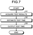
- FIG. 7 is a flowchart illustrating a processing procedure of an estimating process performed by the medical apparatus according to the present embodiment.
- FIG. 1 is a diagram illustrating an exemplary configuration of a test assisting system 1 according to a present embodiment.
- the test assisting system 1 includes an electronic medical record system 10 , a modality 20 , a Picture Archiving and Communication System (PACS) 30 , a trained model generating apparatus 40 , and a medical apparatus 50 .
- the systems and the apparatuses are communicably connected to one another via a network.
- the configuration illustrated in FIG. 1 is merely an example, and the quantities of the systems and the apparatuses may arbitrarily be changed. Further, other apparatuses that are not illustrated in FIG. 1 may be connected to the network.
- the electronic medical record system 10 is configured to manage electronic medical record information including patient information, diagnosis/treatment information, and the like.
- the patient information includes various types of information related to attributes of each patient, such as a patient identifier (ID), the patient's name, gender, height, weight, age, blood type, and the like.
- the diagnosis/treatment information is configured with character strings or the like arbitrarily input by medical providers such as medical doctors regarding the patient and include observations regarding injuries and/or diseases of the patient, treatment plans, and information about various types of diagnoses and treatments related to medical examinations and use of medications.
- the electronic medical record information may be stored in a storage or the like of the electronic medical record system 10 or may be stored in a storage or the like of another apparatuses.
- the modality 20 is configured to generate a medical image by imaging an examined subject (hereinafter “patient”).
- the modality 20 is an image diagnosis apparatus such as an X-ray Computed Tomography (CT) apparatus, a Magnetic Resonance Imaging (MRI) apparatus, an X-ray diagnosis apparatus, or an ultrasound diagnosis apparatus.
- CT X-ray Computed Tomography
- MRI Magnetic Resonance Imaging
- X-ray diagnosis apparatus or an ultrasound diagnosis apparatus.
- RIS Radiology Information System
- the modality 20 is configured to generate the medical image by imaging a site designated in imaging order information, with respect to the examined subject (e.g., a patient) designated in the imaging order information by a radiologist or the like. Further, the modality 20 is configured to transmit the generated medical image to the PACS 30 .
- the PACS 30 is configured to receive, store, and manage the medical image generated by the modality 20 .
- the PACS 30 is configured to store the medical image into a storage thereof or the like, so as to be kept in correspondence with information such as a patient ID, a test ID, a test date/time, and the like.
- the PACS 30 has stored, in a storage thereof or the like, an image interpretation report describing an interpretation result acquired by interpreting the medical image of the patient, and the like.
- the image interpretation report may be stored in a storage or the like of another apparatuses so as to be kept in correspondence with information such as the test ID.
- the trained model generating apparatus 40 is configured to generate a trained model that estimates a test time of a biological valve.
- the trained model generating apparatus 40 is configured to acquire training data from the electronic medical record system 10 , the modality 20 , and the PACS 30 and to store the acquired training data into a storage thereof or the like.
- the trained model generating apparatus 40 may store the training data into a storage or the like of another apparatuses.
- the medical apparatus 50 is configured to estimate a test time of the biological valve. Further, the medical apparatus 50 is configured to output the estimated test time in display or the like.
- the electronic medical record system 10 , the PACS 30 , the trained model generating apparatus 40 , and the medical apparatus 50 are each realized by using a computer apparatuses such as a server, a workstation, or the like.
- the test assisting system 1 is configured to assist the process of identifying the test time of the biological valve, by using Artificial Intelligence (AI) such as the trained model.
- AI is technology for performing various types of processes such as assessing and estimating.
- AI is generated through machine learning such as reinforcement learning, supervised learning, unsupervised learning, deep learning, or the like. Instead of these learning methods, AI may be generated by using other methods.
- FIG. 2 is a chart for explaining an example of the trained model.
- a test includes test items such as an open/close state of the biological valve, a blood flow amount of the biological valve, blood pressure, and an amount of lime adhering to the biological valve. Tests A, B, C, and D were carried out at mutually-different times.
- test A As illustrated in FIG. 2 , let us discuss an example in which test A was carried out when an arbitrary time period had elapsed since the biological valve was placed. Let us assume that the test result of test A indicates that the open/close state of the biological valve was “normal”, the blood flow amount of the biological valve was “normal”, the blood pressure was “slightly high”, and the amount of lime was “equal to or smaller than a threshold value”.
- the open/close state of the biological valve is determined by, for example, whether the difference between a closed state of the biological valve and an open state of the biological valve is equal to or larger than a threshold value.
- the open/close state of the biological valve may be determined by whether an open/close angle, which is the difference in the angle between when the biological valve is open and when the biological valve is closed, is equal to or larger than a threshold value. In test A, because the open/close angle of the biological valve is equal to or larger than the threshold value, the open/close state is determined to be “normal”.
- test result of test B indicates that the open/close state of the biological valve was “normal”, the blood flow amount of the biological valve was “normal”, the blood pressure was “slightly high”, and the amount of lime was “equal to or smaller than the threshold value”.
- the trained model determines the test times of the next test and thereafter, on the basis of a chronological change between the test result of test A and the test result of test B. For example, on the basis of the difference corresponding to the chronological change between the open/close angle of test A and the open/close angle of test B, the trained model determines the test times of the next test and thereafter. In the example in FIG.
- the trained model determines that the time at which an abnormality may occur to the biological valve is approaching, on the basis of the chronological change in the open/close angle of the biological valve. In other words, the trained model determines that the next test time is in three months.
- the trained model determines the test times of the next test and thereafter, on the basis of the chronological change between the test result of test B and the test result of test C.
- the trained model determines that the time at which an abnormality may occur to the biological valve is further approaching, on the basis of the chronological change in the open/close angle of the biological valve. In other words, the trained model determines that the next test time is in one month.
- test result of test D indicates that the open/close state of the biological valve was “abnormal”, the blood flow amount of the biological valve was “abnormal”, the blood pressure was “slightly high”, and the amount of lime was “larger than the threshold value”. Further, because the test result of test D indicates the abnormalities, a medical provider such as a medical doctor determines that the biological valve needs to be replaced.
- the trained model was described as being configured to determine the test times of the next test and thereafter on the basis of the chronological change between the two tests, namely the immediately preceding test result and the current test result. However, the number of test results used for the determination may be three or more. It is also acceptable to use all the test results since the biological valve was placed.
- FIG. 3 is a block diagram illustrating an exemplary configuration of the trained model generating apparatus 40 according to the present embodiment.
- the trained model generating apparatus 40 according to the present embodiment includes a network interface 410 , a storage 420 , an input interface 430 , a display 440 , and a processing circuitry 450 .
- the network interface 410 is connected to the processing circuitry 450 and is configured to control transfer of various types of data and communication performed with the electronic medical record system 10 , the modality 20 , the PACS 30 , and the medical apparatus 50 , via the network. More specifically, the network interface 410 is configured to receive various types of information from the systems and to output the received information to the processing circuitry 450 .
- the network interface 410 is realized by using a network card, a network adaptor, a Network Interface Controller (NIC), or the like.
- the storage 420 is connected to the processing circuitry 450 and is configured to store therein various types of data.
- the storage 420 is realized by using a semiconductor memory element such as a Random Access Memory (RAM) or a flash memory, or a hard disk, an optical disk, or the like.
- the storage 420 has stored therein training data 421 used for generating the trained model.
- the input interface 430 is configured to convert input operations received from an operator into electrical signals and to output the electrical signals to the processing circuitry 450 .
- the input interface 430 is realized by using an input device such as a trackball, a switch button, a mouse, a keyboard, a touchpad on which an input operation is performed by touching an operation surface thereof, a touch screen in which a display screen and a touchpad are integrally formed, a contactless input interface using an optical sensor, an audio input interface, and/or the like.
- the input interface 430 may be a controlling circuit such as a connection interface or the like configured to receive an electronic signal corresponding to an operation, from an operation device provided separately from the trained model generating apparatus 40 .
- the display 440 is configured to display various types of information and various types of images output from the processing circuitry 450 .
- the display 440 is realized by using a display device such as an organic Electroluminescence (EL) monitor, a liquid crystal monitor, a Cathode Ray Tube (CRT) monitor, or a touch panel.
- EL organic Electroluminescence
- CRT Cathode Ray Tube
- the display 440 is configured to display a Graphical User Interface (GUI) for receiving instructions from the operator, various types of display-purpose image data, and various types of processing results acquired by the processing circuitry 450 .
- GUI Graphical User Interface
- the processing circuitry 450 is configured to control constituent elements of the trained model generating apparatus 40 .
- the processing circuitry 450 is realized by using a processor. More specifically, the processing circuitry 450 according to the present embodiment includes an acquiring function 451 and a generating function 452 .
- the processing functions executed by the constituent elements of the processing circuitry 450 illustrated in FIG. 3 namely, the acquiring function 451 and the generating function 452 , are stored in the storage 420 in the form of computer-executable programs.
- the processing circuitry 450 is a processor configured to realize the functions corresponding to the programs by reading and executing the programs from the storage 420 .
- the processing circuitry 450 that has read the programs has the functions illustrated within the processing circuitry 450 in FIG. 3 .
- all the processing functions of the acquiring function 451 and the generating function 452 may be recorded in the storage 420 in the form of a single computer-executable program.
- the program may be referred to as a generation processing program.
- the processing circuitry 450 is configured to realize the acquiring function 451 and the generating function 452 corresponding to the generation processing program, by reading the generation processing program from the storage 420 and executing the read generation processing program.
- the acquiring function 451 is configured to acquire the training data 421 used for generating the trained model.
- FIG. 4 is a drawing illustrating examples of the input/output relationships of the trained model.
- the training data 421 on the input side includes test result information.
- the test result information is information including a test result of each of the tests that are related to the open/close state of the biological valve and were carried out at two or more different times. In other words, the test result information includes the two or more test results of the tests related to the open/close state of the biological valve.
- test result information is information indicating open/close angles of the biological valve at the mutually-different times respectively derived from pieces of CT image data acquired at the two or more mutually-different times.
- Test time information is information indicating one of a test time for a follow-up observation and a test time for replacing the biological valve, the test time being determined by a medical provider such as a medical doctor on the basis of the test results.
- the test result information includes date/time information indicating when the tests were performed.
- the training data 421 on the output side includes test time information.
- the test time information is information indicating one of a test time for a follow-up observation of the biological valve and a test time for replacing the biological valve.
- the test time information is information indicating the one of the test time for the follow-up observation of the biological valve and the test time for replacing the biological valve, the test time being determined by a medical provider such as a medical doctor.
- the acquiring function 451 is configured to acquire the training data 421 , for example, from the electronic medical record system 10 , the modality 20 , or the PACS 30 .
- the acquiring function 451 is configured to store the acquired training data 421 into the storage 420 .
- the generating function 452 is configured to generate the trained model. More specifically, as presented under the learning in FIG. 4 , the generating function 452 is configured to input the training data 421 to a neural network, for example. In other words, the generating function 452 inputs the test result information to the input side and inputs test times to the output side.
- the trained model generated in this manner is configured so as to output test time information indicating a test time of a biological valve of a patient, upon receiving an input of test result information.
- the generating function 452 is configured to generate a trained model for each of different attributes of patients. Accordingly, the trained model is able to estimate one of the test time for a follow-up observation of the biological valve and the test time for replacing the biological valve that corresponds to attributes of the patient.
- the training data 421 may include patient information related to attributes of the patient having the biological valve.
- the acquiring function 451 is configured to acquire the patient information from the electronic medical record system 10 .
- the generating function 452 is configured to generate a trained model by inputting the patient information and the test result information to the input side and inputting test times to the output side. As a result, the trained model is able to estimate one of a test time for a follow-up observation of the biological valve and a test time for replacing the biological valve that corresponds to the attributes of the patient.
- FIG. 5 is a block diagram illustrating an exemplary configuration of the medical apparatus 50 according to the present embodiment.
- the medical apparatus 50 according to the present embodiment includes a network interface 510 , a storage 520 , an input interface 530 , a display 540 , and a processing circuitry 550 .
- the network interface 510 is connected to the processing circuitry 550 and is configured to control transfer of various types of data and communication performed with the electronic medical record system 10 , the modality 20 , the PACS 30 , and the trained model generating apparatus 40 , via the network. More specifically, the network interface 510 is configured to receive various types of information from the systems and to output the received information to the processing circuitry 550 .
- the network interface 510 is realized by using a network card, a network adaptor, a Network Interface Controller (NIC), or the like.
- the storage 520 is connected to the processing circuitry 550 and is configured to store therein various types of data.
- the storage 520 is realized by using a semiconductor memory element such as a Random Access Memory (RAM) or a flash memory, or a hard disk, an optical disk, or the like.
- the storage 520 has stored therein a trained model 521 configured to estimate test times of biological valves.
- the input interface 530 is configured to convert input operations received from an operator into electrical signals and to output the electrical signals to the processing circuitry 550 .
- the input interface 530 is realized by using an input device such as a trackball, a switch button, a mouse, a keyboard, a touchpad on which an input operation is performed by touching an operation surface thereof, a touch screen in which a display screen and a touchpad are integrally formed, a contactless input interface using an optical sensor, an audio input interface, and/or the like.
- the input interface 530 may be a controlling circuit such as a connection interface or the like configured to receive an electronic signal corresponding to an operation, from an operation device provided separately from the medical apparatus 50 .
- the display 540 is configured to display various types of information and various types of images output from the processing circuitry 550 .
- the display 540 is realized by using a display device such as an organic Electroluminescence (EL) monitor, a liquid crystal monitor, a Cathode Ray Tube (CRT) monitor, or a touch panel.
- EL organic Electroluminescence
- CRT Cathode Ray Tube
- the display 540 is configured to display a Graphical User Interface (GUI) for receiving instructions from the operator, various types of display-purpose image data, and various types of processing results acquired by the processing circuitry 550 .
- GUI Graphical User Interface
- the processing circuitry 550 is configured to control constituent elements of the medical apparatus 50 .
- the processing circuitry 550 is realized by using a processor. More specifically, the processing circuitry 550 according to the present embodiment includes a trained model acquiring function 551 , an acquiring function 552 , an estimating function 553 , and an output function 554 .
- the processing functions executed by the constituent elements of the processing circuitry 550 illustrated in FIG. 5 namely, the trained model acquiring function 551 , the acquiring function 552 , the estimating function 553 , and the output function 554 , are stored in the storage 520 in the form of computer-executable programs.
- the processing circuitry 550 is a processor configured to realize the functions corresponding to the programs by reading and executing the programs from the storage 520 .
- the processing circuitry 550 that has read the programs has the functions illustrated within the processing circuitry 550 in FIG. 5 .
- all the processing functions of the trained model acquiring function 551 , the acquiring function 552 , the estimating function 553 , and the output function 554 may be recorded in the storage 520 in the form of a single computer-executable program.
- the program may be referred to as a display processing program.
- the processing circuitry 550 is configured to realize the trained model acquiring function 551 , the acquiring function 552 , the estimating function 553 , and the output function 554 corresponding to the display processing program, by reading the display processing program from the storage 520 and executing the read display processing program.
- the trained model acquiring function 551 is configured to acquire the trained model 521 from the trained model generating apparatus 40 . Further, the trained model acquiring function 551 is configured to store the acquired trained model 521 into the storage 520 .
- the acquiring function 552 is an example of a receiving unit.
- the acquiring function 552 is configured to receive an input of the test result information including the test result of each of the tests that are related to the biological valve and were carried out at two or more different times.
- the acquiring function 552 is configured to acquire the test result information from the electronic medical record system 10 , the modality 20 , or the PACS 30 .
- the test result information includes information indicating the open/close state of the biological valve such as the open/close angle of the biological valve.
- the acquiring function 552 is configured to receive inputs of the patient information related to the attributes of the patient having the biological valve and the test result information.
- the acquiring function 552 is configured to acquire the patient information from the electronic medical record system 10 .
- the estimating function 553 is an example of an estimating unit. On the basis of a chronological change in the open/close state of the biological valve derived from the test result information received by the acquiring function 552 , the estimating function 553 is configured to estimate one of a test time for a follow-up observation of the biological valve and a test time for replacing the biological valve. More specifically, the estimating function 553 is configured to estimate the test time of the biological valve, by inputting the test result information to the trained model 521 that estimates the test time of the biological valve on the basis of the test result information. In other words, the estimating function 553 is configured to estimate the test time of the biological valve, by inputting the test result information to the trained model 521 acquired by the trained model acquiring function 551 from the trained model generating apparatus 40 .
- the estimating function 553 when estimating a test time corresponding to attributes of the patient, is configured to estimate one of a test time for a follow-up observation of the biological valve and a test time for replacing the biological valve, on the basis of the patient information and the test result information. Further, when estimating a test time corresponding to the attributes of the patient by using the trained model 521 , the estimating function 553 is configured to use the patient information in accordance with the trained model 521 acquired by the trained model acquiring function 551 . When having acquired the trained model 521 generated for each of the attributes of patients, the estimating function 553 is configured to select one of the trained models 521 according to the attributes of the patient indicated by the patient information acquired by the acquiring function 552 .
- the estimating function 553 is configured to estimate a test time of the biological valve, by inputting the test result information to the trained model 521 that estimates the test time of the biological valve on the basis of the test result information.
- the estimating function 553 is configured to estimate a test time of the biological valve, by inputting the attribute information and the test result information to the trained model 521 that estimates the test time of the biological valve on the basis of the attribute information and the test result information.
- the output function 554 is an example of an output unit.
- the output function 554 is configured to output the test time estimated by the estimating function 553 .
- the output function 554 is configured to cause a test schedule screen G 1 to display the test time estimated by the estimating function 553 .
- FIG. 6 is a drawing illustrating an example of the test schedule screen G 1 .
- the test schedule screen G 1 is a screen displaying a test schedule of a selected patient.
- the test schedule screen G 1 includes a time-series display region G 11 , a test progress display region G 12 , a detail display region G 13 .
- the time-series display region G 11 is a region for displaying events arranged in a time series for each type of events.
- the time-series display region G 11 in FIG. 6 displays consultations, ultrasound image tests, and CT image tests, as types of events. Possible examples of the types of events are not limited to consultations, ultrasound image tests, and CT image tests and may include other events.
- the time-series display region G 11 contains non-display icons G 111 , current-display icons G 112 , and schedule icons G 113 .
- the non-display icons G 111 and the current-display icons G 112 are icons indicating test times at which tests were carried out on the biological valve.
- the non-display icons G 111 are icons indicating events that are among the events of the patient, but are not displayed in the detail display region G 13 .
- the current-display icons G 112 are icons indicating events that are among the events of the patient and are displayed in the detail display region G 13 .
- the schedule icons G 113 are icons indicating the test dates/times of the biological valve estimated by the estimating function 553 .
- the schedule icons G 113 may receive an operation to make an appointment for a test of an event corresponding to any of the test dates/times estimated by the estimating function 553 .
- the output function 554 is configured to output the test schedule screen G 1 that has arranged thereon, in the time series, the non-display icons G 111 and the current-display icons G 112 serving as examples of the first icon indicating the test times at which tests were carried out on the biological valve, as well as the schedule icons G 113 serving as examples of the second icon indicating the test times of the biological valve estimated by the estimating function 553 .
- the test progress display region G 12 is a display region for displaying a graph acquired by plotting test results of the biological valve. Further, the test progress display region G 12 may have predicted values plotted, which may be exhibited when the tests are carried out at the test times indicated by the schedule icons G 113 .
- the detail display region G 13 is a region for displaying details of the icons selected in the time-series display region G 11 .
- the test schedule screen G 1 in FIG. 6 includes a detail display region G 13 displaying observations corresponding to the current-display icon G 112 for the “consultations”, another detail display region G 13 displaying an ultrasound image corresponding to the current-display icon G 112 for the “ultrasound image tests”, and yet another detail display region G 13 displaying a CT image corresponding to the current-display icon G 112 for the “CT image tests”.
- the output function 554 is configured to output the test schedule screen G 1 including the non-display icons G 111 , the current-display icons G 112 , and the schedule icons G 113 that are arranged in the time series, as well as the test results of the biological valve tested at the test times indicated by the current-display icons G 112 .
- FIG. 7 is a flowchart illustrating a processing procedure of the estimating process performed by the medical apparatus 50 according to the present embodiment.
- the acquiring function 552 acquires test result information including the test result of each of the tests that are related to the biological valve and were carried out at two or more different times (step S 1 ).
- the estimating function 553 estimates a test time of the biological valve (step S 2 ). For example, the estimating function 553 estimates one of a test time for a follow-up observation of the biological valve and a test time for replacing the biological valve.
- the output function 554 outputs the estimated test time (step S 3 ). For example, the output function 554 causes the test schedule screen G 1 to display the test time.
- the medical apparatus 50 thus ends the estimating process.
- the acquiring function 552 is configured to receive the input of the test result information including the test result of each of the tests that are related to the biological valve and were carried out at the two or more different times.
- the estimating function 553 is configured to estimate one of the test time for the follow-up observation of the biological valve and the test time for replacing the biological valve.
- the output function 554 is configured to output the test time estimated by the estimating function 553 .
- the output function 554 causes the time-series display region G 11 on the test schedule screen G 1 to display the test time estimated by the estimating function 553 . Accordingly, medical providers such as medical doctors are able to reference the test time of the biological valve displayed on the test schedule screen G 1 . Consequently, the medical apparatus 50 is able to assist the process of identifying the test time of the biological valve.
- the estimating function 553 is configured to estimate the test time of the biological valve, on the basis of the chronological change in the open/close state of the biological valve derived from the test result information.
- the test result information may include information indicating test results of the blood flow amount of the biological valve and the blood pressure.
- the acquiring function 451 is configured to acquire the test result information including the blood flow amount of the biological valve and the blood pressure measured from an ultrasound image or the like.
- the generating function 452 is configured to generate a trained model 521 , by inputting the test result information including the blood flow amount of the biological valve and the blood pressure and the test time information to a neural network or the like.
- the acquiring function 552 is configured to receive an input of the test result information including the blood flow amount of the biological valve and the blood pressure.
- the estimating function 553 is configured to estimate a test time of the biological valve. For example, the estimating function 553 is configured to estimate the test time of the biological valve, by inputting the test result information indicating the blood flow amount of the biological valve and the blood pressure, to the trained model 521 generated by the generating function 452 .
- the estimating function 553 is configured to estimate the test time of the biological valve, on the basis of the open/close state of the biological valve derived from the test result information.
- the test result information may include information indicating a test result of the amount of lime adhering to the biological valve.
- the acquiring function 451 is configured to acquire the test result information including the amount of lime adhering to the biological valve that was measured from CT image data, which is three-dimensional data.
- the generating function 452 is configured to generate a trained model 521 by inputting the test result information indicating the amount of lime adhering to the biological valve and the test time information to a neural network or the like.
- the acquiring function 552 is configured to receive an input of the test result information including the amount of lime adhering to the biological valve.
- the estimating function 553 is configured to estimate a test time of the biological valve. For example, the estimating function 553 is configured to estimate the test time of the biological valve, by inputting the test result information indicating the amount of lime adhering to the biological valve, to the trained model 521 generated by the generating function 452 .
- the estimating function 553 is configured to estimate the test time by using the trained model 521 .
- the estimating function 553 may estimate the test time by using other methods besides the trained model 521 .
- the estimating function 553 may estimate the test time by using an information table indicating test times corresponding to chronological changes in the open/close state of the biological valve derived from the test result information. Further, when there is an information table for each of various attributes of patients, the estimating function 553 may estimate a test time on the basis of the patient information and the test result information.
- each of the processing circuitries 450 and 550 may be configured by combining together a plurality of independent processors, so that the processing functions are realized as a result of the processors executing the programs. Further, the processing functions of each of the processing circuitries 450 and 550 may be realized as being distributed among or integrated together into one or more processing circuitries 450 , 550 , as appropriate.
- processor denotes, for example, a Central Processing Unit (CPU), a Graphics Processing Unit (GPU), or a circuit such as an Application Specific Integrated Circuit (ASIC) or a programmable logic device (e.g., a Simple Programmable Logic Device [SPLD], a Complex Programmable Logic Device [CPLD], or a Field Programmable Gate Array [FPGA]).
- CPU Central Processing Unit
- GPU Graphics Processing Unit
- ASIC Application Specific Integrated Circuit
- SPLD Simple Programmable Logic Device
- CPLD Complex Programmable Logic Device
- FPGA Field Programmable Gate Array
- each of the processors of the present embodiments does not necessarily have to be structured as a single circuit. It is also acceptable to structure one processor by combining together a plurality of independent circuits so as to realize the functions thereof.
- the programs executed by the processors are provided as being incorporated, in advance, in a Read Only Memory (ROM), a storage unit, or the like.
- the programs may be provided as being recorded on a computer-readable storage medium such as a Compact Disk Read-Only Memory (CD-ROM), a Flexible Disk (FD), a Compact Disk Recordable (CD-R), a Digital Versatile Disk (DVD), or the like, in a file in a format that is installable or executable by these devices.
- the programs may be stored in a computer connected to a network such as the Internet so as to be provided or distributed as being downloaded via the network.
- the programs are structured with modules including the functional units. In the actual hardware, as a result of a CPU reading and executing the programs from a storage medium such as a ROM, the modules are loaded into a main memory and generated in the main memory.
- the constituent elements of the apparatuses in the drawings are based on functional concepts. Thus, it is not necessary to physically configure the constituent elements as indicated in the drawings. In other words, specific modes of distribution and integration of the apparatuses are not limited to those illustrated in the drawings. It is acceptable to functionally or physically distribute or integrate all or a part of the apparatuses in any arbitrary units, depending on various loads and the status of use. Further, all or an arbitrary part of the processing functions performed by the apparatuses may be realized by a CPU and a program analyzed and executed by the CPU or may be realized as hardware using wired logic.
- a computer such as a personal computer or a workstation to execute a program prepared in advance.
- the program may be distributed via a network such as the Internet. Further, the program may be executed, as being recorded on a computer-readable recording medium such as a hard disk, a flexible disk (FD), a CD-ROM, a Magneto-Optical (MO) disk, a DVD, or the like and being read from the recording medium by a computer.
- a computer such as a personal computer or a workstation
- a program may be distributed via a network such as the Internet.
- the program may be executed, as being recorded on a computer-readable recording medium such as a hard disk, a flexible disk (FD), a CD-ROM, a Magneto-Optical (MO) disk, a DVD, or the like and being read from the recording medium by a computer.
- FD flexible disk
- MO Magneto-Optical
Landscapes
- Health & Medical Sciences (AREA)
- Life Sciences & Earth Sciences (AREA)
- Engineering & Computer Science (AREA)
- Public Health (AREA)
- Medical Informatics (AREA)
- Biomedical Technology (AREA)
- General Health & Medical Sciences (AREA)
- Cardiology (AREA)
- Surgery (AREA)
- Heart & Thoracic Surgery (AREA)
- Molecular Biology (AREA)
- Animal Behavior & Ethology (AREA)
- Veterinary Medicine (AREA)
- Pathology (AREA)
- Physics & Mathematics (AREA)
- Biophysics (AREA)
- Physiology (AREA)
- Hematology (AREA)
- Epidemiology (AREA)
- Primary Health Care (AREA)
- Artificial Intelligence (AREA)
- Computer Vision & Pattern Recognition (AREA)
- Psychiatry (AREA)
- Signal Processing (AREA)
- Vascular Medicine (AREA)
- General Business, Economics & Management (AREA)
- Robotics (AREA)
- Business, Economics & Management (AREA)
- Nuclear Medicine, Radiotherapy & Molecular Imaging (AREA)
- Mathematical Physics (AREA)
- Evolutionary Computation (AREA)
- Fuzzy Systems (AREA)
- Transplantation (AREA)
- Data Mining & Analysis (AREA)
- Databases & Information Systems (AREA)
- Measuring And Recording Apparatus For Diagnosis (AREA)
- Measuring Pulse, Heart Rate, Blood Pressure Or Blood Flow (AREA)
- Prostheses (AREA)
- Medical Treatment And Welfare Office Work (AREA)
Abstract
Description
Claims (3)
Applications Claiming Priority (2)
| Application Number | Priority Date | Filing Date | Title |
|---|---|---|---|
| JP2019-159589 | 2019-09-02 | ||
| JP2019159589A JP2021037027A (en) | 2019-09-02 | 2019-09-02 | Medical device and processing program |
Publications (2)
| Publication Number | Publication Date |
|---|---|
| US20210059541A1 US20210059541A1 (en) | 2021-03-04 |
| US11819314B2 true US11819314B2 (en) | 2023-11-21 |
Family
ID=74682059
Family Applications (1)
| Application Number | Title | Priority Date | Filing Date |
|---|---|---|---|
| US16/988,906 Active 2041-10-21 US11819314B2 (en) | 2019-09-02 | 2020-08-10 | Medical apparatus and test assisting method |
Country Status (2)
| Country | Link |
|---|---|
| US (1) | US11819314B2 (en) |
| JP (1) | JP2021037027A (en) |
Citations (6)
| Publication number | Priority date | Publication date | Assignee | Title |
|---|---|---|---|---|
| US20040015233A1 (en) * | 2000-10-09 | 2004-01-22 | Josef Jansen | Cardiac valve prosthesis, especially mitral cardiac valve and method for producing the same |
| US8086471B2 (en) * | 2009-04-24 | 2011-12-27 | Emissary Technologies, Llc | Computer-implemented system and method for electronic medication administration records |
| US20120296382A1 (en) * | 2006-08-24 | 2012-11-22 | Shuros Allan C | Integrated cardiac rhythm management system with heart valve |
| JP2017217474A (en) | 2016-06-07 | 2017-12-14 | 東芝メディカルシステムズ株式会社 | Medical image diagnostic apparatus and medical image processing system |
| US20190378620A1 (en) * | 2018-06-12 | 2019-12-12 | Bittium Biosignals Oy | Method, system and mobile communications device medical for optimizing clinical care delivery |
| US20220104712A1 (en) * | 2019-01-30 | 2022-04-07 | Koninklijke Philips N.V. | Aortic stenosis echocardiographic follow-up expert system |
-
2019
- 2019-09-02 JP JP2019159589A patent/JP2021037027A/en active Pending
-
2020
- 2020-08-10 US US16/988,906 patent/US11819314B2/en active Active
Patent Citations (6)
| Publication number | Priority date | Publication date | Assignee | Title |
|---|---|---|---|---|
| US20040015233A1 (en) * | 2000-10-09 | 2004-01-22 | Josef Jansen | Cardiac valve prosthesis, especially mitral cardiac valve and method for producing the same |
| US20120296382A1 (en) * | 2006-08-24 | 2012-11-22 | Shuros Allan C | Integrated cardiac rhythm management system with heart valve |
| US8086471B2 (en) * | 2009-04-24 | 2011-12-27 | Emissary Technologies, Llc | Computer-implemented system and method for electronic medication administration records |
| JP2017217474A (en) | 2016-06-07 | 2017-12-14 | 東芝メディカルシステムズ株式会社 | Medical image diagnostic apparatus and medical image processing system |
| US20190378620A1 (en) * | 2018-06-12 | 2019-12-12 | Bittium Biosignals Oy | Method, system and mobile communications device medical for optimizing clinical care delivery |
| US20220104712A1 (en) * | 2019-01-30 | 2022-04-07 | Koninklijke Philips N.V. | Aortic stenosis echocardiographic follow-up expert system |
Non-Patent Citations (1)
| Title |
|---|
| Rick, "2014 AHA/ACC Guideline for the Management of Patients With Valvular Heart Disease" [DOI: 10.1161/CIR.0000000000000031 accessed on Sep. 22, 2022, Jun. 10, 2014]. (Year: 2014). * |
Also Published As
| Publication number | Publication date |
|---|---|
| US20210059541A1 (en) | 2021-03-04 |
| JP2021037027A (en) | 2021-03-11 |
Similar Documents
| Publication | Publication Date | Title |
|---|---|---|
| US10984905B2 (en) | Artificial intelligence for physiological quantification in medical imaging | |
| US10628943B2 (en) | Deep learning medical systems and methods for image acquisition | |
| JP7051849B2 (en) | Methods for deep learning medical systems and medical procedures | |
| US11069056B2 (en) | Multi-modal computer-aided diagnosis systems and methods for prostate cancer | |
| US11594002B2 (en) | Overlay and manipulation of medical images in a virtual environment | |
| US20190156947A1 (en) | Automated information collection and evaluation of clinical data | |
| CN108784655A (en) | Rapid evaluation for medical patient and consequences analysis | |
| US11061537B2 (en) | Interactive human visual and timeline rotor apparatus and associated methods | |
| US20240127436A1 (en) | Multi-modal computer-aided diagnosis systems and methods for prostate cancer | |
| CN113261939A (en) | Machine-based risk prediction for perioperative myocardial infarction or complications from medical data | |
| CN109256205B (en) | Method and system for clinical decision support with local and remote analytics | |
| CN111951936B (en) | Medical information processing apparatus | |
| US20220108801A1 (en) | Diagnosis and treatment support system | |
| US11728034B2 (en) | Medical examination assistance apparatus | |
| US11819314B2 (en) | Medical apparatus and test assisting method | |
| EP3965117A1 (en) | Multi-modal computer-aided diagnosis systems and methods for prostate cancer | |
| JP7474568B2 (en) | Medical information display device and medical information display system | |
| JP2018181106A (en) | Device and method for processing medical information | |
| US20220139528A1 (en) | Analysis support apparatus, analysis support system, and analysis support method | |
| US20230218345A1 (en) | Medical information processing apparatus and method | |
| US20220285031A1 (en) | Medical information processing apparatus | |
| US20230240623A1 (en) | Medical information display apparatus, medical information display method, and non-volatile computer-readable storage medium storing therein medical information display program | |
| US20210118568A1 (en) | Medical information processing apparatus and medical information processing method | |
| JP2021117652A (en) | Medical examination support system, medical examination support device, and medical examination support program | |
| Sanchez Gomez | Coronary artery segmentation using Transformer Neural Networks |
Legal Events
| Date | Code | Title | Description |
|---|---|---|---|
| AS | Assignment |
Owner name: CANON MEDICAL SYSTEMS CORPORATION, JAPAN Free format text: ASSIGNMENT OF ASSIGNORS INTEREST;ASSIGNOR:ISHII, HIDEAKI;REEL/FRAME:053442/0152 Effective date: 20200729 |
|
| FEPP | Fee payment procedure |
Free format text: ENTITY STATUS SET TO UNDISCOUNTED (ORIGINAL EVENT CODE: BIG.); ENTITY STATUS OF PATENT OWNER: LARGE ENTITY |
|
| STPP | Information on status: patent application and granting procedure in general |
Free format text: DOCKETED NEW CASE - READY FOR EXAMINATION |
|
| STPP | Information on status: patent application and granting procedure in general |
Free format text: NON FINAL ACTION MAILED |
|
| STPP | Information on status: patent application and granting procedure in general |
Free format text: FINAL REJECTION MAILED |
|
| STPP | Information on status: patent application and granting procedure in general |
Free format text: NOTICE OF ALLOWANCE MAILED -- APPLICATION RECEIVED IN OFFICE OF PUBLICATIONS |
|
| STPP | Information on status: patent application and granting procedure in general |
Free format text: PUBLICATIONS -- ISSUE FEE PAYMENT RECEIVED |
|
| STPP | Information on status: patent application and granting procedure in general |
Free format text: PUBLICATIONS -- ISSUE FEE PAYMENT VERIFIED |
|
| STCF | Information on status: patent grant |
Free format text: PATENTED CASE |