US11774187B2 - Heat transfer fin of fin-tube type heat exchanger - Google Patents
Heat transfer fin of fin-tube type heat exchanger Download PDFInfo
- Publication number
- US11774187B2 US11774187B2 US16/387,113 US201916387113A US11774187B2 US 11774187 B2 US11774187 B2 US 11774187B2 US 201916387113 A US201916387113 A US 201916387113A US 11774187 B2 US11774187 B2 US 11774187B2
- Authority
- US
- United States
- Prior art keywords
- distal
- fin
- heat transfer
- surrounding part
- area
- Prior art date
- Legal status (The legal status is an assumption and is not a legal conclusion. Google has not performed a legal analysis and makes no representation as to the accuracy of the status listed.)
- Active
Links
Images


Classifications
-
- F—MECHANICAL ENGINEERING; LIGHTING; HEATING; WEAPONS; BLASTING
- F28—HEAT EXCHANGE IN GENERAL
- F28F—DETAILS OF HEAT-EXCHANGE AND HEAT-TRANSFER APPARATUS, OF GENERAL APPLICATION
- F28F1/00—Tubular elements; Assemblies of tubular elements
- F28F1/10—Tubular elements and assemblies thereof with means for increasing heat-transfer area, e.g. with fins, with projections, with recesses
- F28F1/12—Tubular elements and assemblies thereof with means for increasing heat-transfer area, e.g. with fins, with projections, with recesses the means being only outside the tubular element
- F28F1/24—Tubular elements and assemblies thereof with means for increasing heat-transfer area, e.g. with fins, with projections, with recesses the means being only outside the tubular element and extending transversely
- F28F1/32—Tubular elements and assemblies thereof with means for increasing heat-transfer area, e.g. with fins, with projections, with recesses the means being only outside the tubular element and extending transversely the means having portions engaging further tubular elements
- F28F1/325—Fins with openings
-
- F—MECHANICAL ENGINEERING; LIGHTING; HEATING; WEAPONS; BLASTING
- F28—HEAT EXCHANGE IN GENERAL
- F28D—HEAT-EXCHANGE APPARATUS, NOT PROVIDED FOR IN ANOTHER SUBCLASS, IN WHICH THE HEAT-EXCHANGE MEDIA DO NOT COME INTO DIRECT CONTACT
- F28D1/00—Heat-exchange apparatus having stationary conduit assemblies for one heat-exchange medium only, the media being in contact with different sides of the conduit wall, in which the other heat-exchange medium is a large body of fluid, e.g. domestic or motor car radiators
- F28D1/02—Heat-exchange apparatus having stationary conduit assemblies for one heat-exchange medium only, the media being in contact with different sides of the conduit wall, in which the other heat-exchange medium is a large body of fluid, e.g. domestic or motor car radiators with heat-exchange conduits immersed in the body of fluid
- F28D1/04—Heat-exchange apparatus having stationary conduit assemblies for one heat-exchange medium only, the media being in contact with different sides of the conduit wall, in which the other heat-exchange medium is a large body of fluid, e.g. domestic or motor car radiators with heat-exchange conduits immersed in the body of fluid with tubular conduits
- F28D1/047—Heat-exchange apparatus having stationary conduit assemblies for one heat-exchange medium only, the media being in contact with different sides of the conduit wall, in which the other heat-exchange medium is a large body of fluid, e.g. domestic or motor car radiators with heat-exchange conduits immersed in the body of fluid with tubular conduits the conduits being bent, e.g. in a serpentine or zig-zag
- F28D1/0477—Heat-exchange apparatus having stationary conduit assemblies for one heat-exchange medium only, the media being in contact with different sides of the conduit wall, in which the other heat-exchange medium is a large body of fluid, e.g. domestic or motor car radiators with heat-exchange conduits immersed in the body of fluid with tubular conduits the conduits being bent, e.g. in a serpentine or zig-zag the conduits being bent in a serpentine or zig-zag
- F28D1/0478—Heat-exchange apparatus having stationary conduit assemblies for one heat-exchange medium only, the media being in contact with different sides of the conduit wall, in which the other heat-exchange medium is a large body of fluid, e.g. domestic or motor car radiators with heat-exchange conduits immersed in the body of fluid with tubular conduits the conduits being bent, e.g. in a serpentine or zig-zag the conduits being bent in a serpentine or zig-zag the conduits having a non-circular cross-section
-
- F—MECHANICAL ENGINEERING; LIGHTING; HEATING; WEAPONS; BLASTING
- F28—HEAT EXCHANGE IN GENERAL
- F28F—DETAILS OF HEAT-EXCHANGE AND HEAT-TRANSFER APPARATUS, OF GENERAL APPLICATION
- F28F2215/00—Fins
- F28F2215/08—Fins with openings, e.g. louvers
-
- F—MECHANICAL ENGINEERING; LIGHTING; HEATING; WEAPONS; BLASTING
- F28—HEAT EXCHANGE IN GENERAL
- F28F—DETAILS OF HEAT-EXCHANGE AND HEAT-TRANSFER APPARATUS, OF GENERAL APPLICATION
- F28F2215/00—Fins
- F28F2215/10—Secondary fins, e.g. projections or recesses on main fins
Definitions
- the present disclosure relates to a heat transfer fin used in a fin-tube type heat exchanger.
- a burner that includes a heat source for radiating heat and a heat exchanger that transfers radiant heat emitted from the heat source and convection heat of combustion gas generated by the burner to a heating medium to heat heating water are disposed in an electric heating apparatus such as a boiler, a water heater, or a hot-water mat.
- the heat exchanger has a tube disposed therein.
- the heating medium flows through the tube, and the combustion gas flows outside the tube. Therefore, heat exchange between the heating medium and the combustion gas is indirectly performed through the tube.
- a heat transfer fin includes a fin body having a plate shape and a plurality of through-holes formed through the fin body and spaced apart from each other in a first direction.
- a flow direction of combustion gas that is to flow along a surface of the fin body is referred to as a second direction
- the fin body includes a distal surrounding part that surrounds a first distal area located at the farthest upstream side of each of the through-holes with respect to the second direction.
- a heat transfer fin includes a fin body having a plate shape and a plurality of through-holes formed through the fin body and spaced apart from each other in a first direction, in which a tube through which a heating medium flows is inserted through each of the through-holes.
- the fin body includes a distal surrounding part that surrounds a first distal area located at the farthest upstream side of the through-hole with respect to the second direction and middle surrounding parts that extend from the distal surrounding part in the second direction and that surround a middle area of the through-hole that is located downstream of the first distal area with respect to the second direction.
- the distal surrounding part has a smaller width than the middle surrounding parts.
- a heat transfer fin includes a fin body having a plate shape and a plurality of through-holes formed through the fin body and spaced apart from each other in a first direction, in which a tube through which a heating medium flows is inserted through each of the through-holes.
- a flow direction of combustion gas that is to flow along the fin body is referred to as a second direction
- the fin body includes a distal surrounding part that surrounds a first distal area located at the farthest upstream side of the through-hole with respect to the second direction.
- a reference curve refers to a virtual curve that has a curvilinear shape corresponding to an inner boundary of the distal surrounding part by which the distal surrounding part and the first distal area are divided from each other, maintains a predetermined distance from the inner boundary on the same plane, and passes through intersections of an outer boundary of the distal surrounding part by which the distal surrounding part and the outside of the fin body are divided from each other and a reference straight line that is a virtual straight line drawn parallel to the first direction, at least part of the outer boundary located to correspond to the reference curve is located inward of the reference curve, in at least one of the plurality of distal surrounding parts that surround the first distal areas of the plurality of through-holes, respectively.
- a heat transfer fin includes a fin body having a plate shape and a plurality of through-holes formed through the fin body and spaced apart from each other in a first direction, in which a tube through which a heating medium flows is inserted through each of the through-holes.
- a flow direction of combustion gas that is to flow along the fin body is referred to as a second direction
- the fin body includes a distal surrounding part that surrounds a first distal area located at the farthest upstream side of the through-hole with respect to the second direction.
- a reference curve refers to a virtual curve that has a curvilinear shape corresponding to an outer boundary of the distal surrounding part by which the distal surrounding part and the outside of the fin body are divided from each other, maintains a predetermined distance from the outer boundary on the same plane, and passes through intersections of an inner boundary of the distal surrounding part by which the distal surrounding part and the first distal area are divided from each other and a reference straight line that is a virtual straight line drawn parallel to the first direction, at least part of the inner boundary located to correspond to the reference curve is located outward of the reference curve, in at least one of the plurality of distal surrounding parts that surround the first distal areas of the plurality of through-holes, respectively.
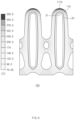
- FIG. 1 is a front view illustrating a heat transfer fin according to a first embodiment of the present disclosure
- FIG. 2 is a blowup of region A in FIG. 1 ;
- FIG. 3 is an enlarged front view illustrating a partial area of a heat transfer fin according to one modified example of the first embodiment of the present disclosure
- FIG. 4 is an enlarged front view illustrating a partial area of a heat transfer fin according to another modified example of the first embodiment of the present disclosure
- FIG. 5 is a blowup of an outer body part in FIG. 1 ;
- FIG. 6 is a view illustrating the temperature distribution of an existing heat transfer fin
- FIG. 7 is a view illustrating the temperature distribution of the heat transfer fin according to the first embodiment of the present disclosure into which a fin body structure is introduced;
- FIG. 9 is a view illustrating the temperature distribution of the heat transfer fin according to the first embodiment of the present disclosure into which the outer body part is introduced;
- FIG. 12 is a view illustrating the temperature distribution of an existing heat transfer fin into which flanges are introduced
- FIG. 14 is a view illustrating the temperature distribution of the heat transfer fin according to the third embodiment of the present disclosure.
- the heat transfer fin 1 includes a fin body 10 and through-holes 20 formed through the fin body 10 .
- the fin body 10 includes a distal surrounding part 111 that surrounds a partial area of each of the through-holes 20 .
- the horizontal direction indicated by a double arrow in FIG. 1 is a first direction D 1 in which the through-holes 20 are spaced apart from each other.
- the vertical direction indicated by a single arrow in FIG. 1 is a second direction D 2 in which combustion gas is to flow in a heat exchanger in which the heat transfer fin 1 is used.
- the fin body 10 is a plate-shaped component that transfers heat to the tubes.
- the fin body 10 may be formed in a plate shape that is perpendicular to a reference direction in which the tubes extend, such that the fin body may have a plate shape with a planar surface.
- the plurality of through-holes 20 are formed through the fin body 10 and spaced apart from each other along the first direction D 1 , and through-sections 12 are cut into the fin body 10 along the second direction D 2 from an end portion located at the upstream side of the fin body 10 .
- the fin body 10 may be formed of a metallic material that has a high thermal conductivity and can be shaped into various shapes.
- the tubes are inserted through the through-holes 20 , which are formed through the fin body 10 , and combined with the fin body 10 . Heat transferred to the fin body 10 may be transferred to the tubes.
- the through-holes 20 may have a slightly smaller area than the tubes, and the tubes may be press fitted into the through-holes 20 .
- both the tubes and the fin body 10 may be formed of metal and may be combined with each other by welding.
- a method of combining the tubes and the fin body 10 together is not limited thereto.
- the fin body 10 has the through-holes 20 and the through-sections 12 formed therein.
- the plurality of through-holes 20 and through-sections 12 may be formed in the fin body 10 .
- the fin body 10 may have intervening sections 14 , each of which is located between the through-holes 20 adjacent to each other and downstream of a corresponding one of the through-sections 12 with respect to the second direction D 2 .
- Flanges 40 which will be described below, may be formed in the intervening sections 14 , respectively.
- partial areas of the fin body 10 may be surrounding parts 11 that will be described below.
- the through-holes 20 are formed through the fin body 10 such that the tubes through which a heating medium flows are inserted through the through-holes 20 .
- the tubes are inserted through the through-holes 20 , and therefore the through-holes 20 are formed as openings that are open in the reference direction which the tubes extend.
- the reference direction is a direction into or out of the plane of the drawing.
- the through-holes 20 may be of a circular type formed in a circular shape or an oval type formed in an elliptical shape.
- circular tubes having a circular cross-section, or oval tubes having an elliptical cross-section may be inserted through the through-holes 20 .
- Each of the tubes has a heat transfer area to receive heat through contact with the combustion gas. Assuming that a flat tube, a circular tube, and an oval tube have the same cross-sectional area, the heat transfer area of the flat tube may be larger than the heat transfer area of the circular tube or the oval tube, and therefore the thermal efficiency of the flat tube may higher than the thermal efficiency of the circular tube or the oval tube.
- the time that heating water flowing through the flat tube starts to boil may be similar to the time that heating water flowing through the circular tube or the oval tube starts to boil.
- lime is more likely to be generated in the flat tube than in the circular tube or the oval tube.
- the area that meets the combustion gas first, among distal ends of the flat tube that are identifiable in the direction in which the cross-section of the flat tube extends, may be overheated. Therefore, heating water may be more likely to start to boil, and lime may be more likely to be generated.
- the first distal area 21 and the second distal area 22 of the through-hole 20 are formed farthest upstream and downstream of the middle area 23 of the through-hole 20 , respectively, with respect to the second direction D 2 . Accordingly, the middle area 23 is an adjacent area located downstream of the first distal area 21 and upstream of the second distal area 22 .
- the middle area 23 may be implemented with two arcs that have line symmetry with respect to the center line parallel to the second direction D 2
- the first distal area 21 and the second distal area 22 may be implemented with two arcs that have line symmetry with respect to the center line parallel to the first direction D 1
- the listed arcs may be continuously combined with each other to form the through-hole 20 .
- the radius of curvature of the profile of the first distal area 21 may be smaller than the radii of curvature of the arcs constituting the middle area 23 . Accordingly, a curvature variation occurs at an inner contact point (reference numeral 114 of FIG. 2 ) where two different arcs meet each other.
- the plurality of through-holes 20 may be spaced apart from each other along the direction that is perpendicular to the second direction D 2 and the reference direction.
- the direction is the first direction D 1 .
- the through-holes 20 may be spaced at predetermined intervals from each other along the first direction D 1 .
- FIG. 1 illustrates one example that the fin body 10 includes a total of six through-holes 20 , the number of through-holes 20 is not limited thereto.
- FIG. 2 is an enlarged front view illustrating region A of the heat transfer fin 1 according to the first embodiment of the present disclosure.
- the fin body 10 included in the heat transfer fin 1 according to the first embodiment of the present disclosure includes the surrounding parts 11 .
- Each of the surrounding parts 11 includes middle surrounding parts 112 and the distal surrounding part 111 .
- At least opposite sides of the middle area 23 of each through-hole 20 that are oriented in the first direction D 1 are surrounded by the middle surrounding parts 112 , and the periphery of the first distal area 21 of the through-hole 20 is surrounded by the distal surrounding part 111 .
- the middle surrounding parts 112 extend from the distal surrounding part 111 in the second direction D 2 . Accordingly, the surrounding part 11 surrounds at least a partial area of the through-hole 20 .
- the plurality of surrounding parts 11 may be disposed around the plurality of through-holes 20 , respectively, and may have different shapes.
- the middle surrounding parts 112 of each surrounding part 11 are partial areas of the fin body 10 that surround the middle area 23 of the corresponding through-hole 20 .
- the middle surrounding parts 112 protrude outward from the periphery of the middle area 23 of the through-hole 20 by a predetermined width.
- the profiles of outer boundaries 1121 of the middle surrounding parts 112 are the same as the profile of the middle area 23 of the through-hole 20 and are spaced apart from the middle area 23 by the predetermined width.
- the width of each middle surrounding part 112 may be defined as the shortest distance from one point on an inner boundary 1122 of the middle surrounding part 112 to the outer boundary 1121 of the middle surrounding part 112 .
- the width of the middle surrounding part 112 may remain a constant width of W 1 for the entirety of the middle surrounding part 112 .
- the distal surrounding part 111 is a partial area of the fin body 10 that surrounds the first distal area 21 of the through-hole 20 .
- the distal surrounding part 111 protrudes outward from the periphery of the first distal area 21 of the through-hole 20 , similarly to the middle surrounding parts 112 .
- the distal surrounding part 111 may be continuous with the middle surrounding parts 112 . Accordingly, two outer contact points 113 and two inner contact points 114 , which are connection points, may be formed on the planes where the distal surrounding part 111 and the middle surrounding parts 112 make contact with each other. Because the widths of the middle surrounding parts 112 remain W 1 , the distances from the outer contact points 113 to the inner contact points 114 may be equal to the widths W 1 of the middle surrounding parts 112 .
- a groove may be formed in an area corresponding to a distal surrounding part, or an area of a surrounding part that is located upstream may be cut, to prevent heat from being concentrated on an upstream side of the tube in order to prevent generation of lime and acoustic boiling noise in the tube.
- the heat exchange area at the upstream side of the flat tube is wide, and therefore it may be difficult to reduce the amount of lime (LM of FIG. 8 ) formed in the flat tube, by only forming some grooves on a surrounding part disposed around the flat tube or cutting a portion of the farthest upstream side of the surrounding part. That is because the remaining portions of the surrounding part other than the grooves or the cut portion are disposed around the tube as they are and hence heat of combustion gas is still concentrated through the remaining portions and transferred to the tube.
- LM of FIG. 8 amount of lime
- the distal surrounding part 111 may be formed such that the shortest distance W 1 between an inner boundary 1112 and an outer boundary 1111 that is obtained at the farthest downstream side of the distal surrounding part 111 with respect to the second direction D 2 is greater than the shortest distance W 3 between the inner boundary 1112 and the outer boundary 1111 that is obtained in another area of the distal surrounding part 111 .
- the distal surrounding part 111 is formed in the shape in which the area is entirely reduced.
- the degree of concentration of heat on the distal surrounding part 111 may be reduced, which makes it possible to prevent the heat transfer fin 1 from being overheated, reduce the amount of lime generated in the tube, and reduce acoustic boiling noise.
- the middle area 23 and the first distal area 21 of the through-hole 20 are divided from each other at the inner contact points 114 that are connection points, and therefore the definition of the curve constituting the profile of the through-hole 20 may also be changed. Furthermore, the outer boundary 1111 of the distal surrounding part 111 and the outer boundaries 1121 of the middle surrounding parts 112 meet at the outer contact points 113 that are connection points, and therefore the outer boundary 1111 of the distal surrounding part 111 and the outer boundaries 1121 of the middle surrounding parts 112 may be represented by differently defined curves at the outer contact points 113 . Straight lines that connect the inner contact points 114 and the outer contact points 113 may be parallel to the first direction D 1 .
- One through-section 12 which is cut into the fin body 10 , is formed between two distal surrounding parts 111 that surround first distal areas 21 of two through-holes 20 that are adjacent to each other along the first direction D 1 .
- the through-section 12 is formed through the fin body 10 such that the through-section 12 is open in the opposite direction to the second direction D 2 from the inside of the fin body 10 . Due to the formation of the through-section 12 , the distal surrounding parts 111 and the middle surrounding parts 112 naturally meet the outside of the fin body 10 . That is, the through-section 12 is located between the adjacent surrounding parts 11 , and the crooked profile of the fin body 10 is formed by the through-section 12 and the surrounding parts 11 .
- the through-section 12 may have a shape, the width of which increases toward the opposite direction to the second direction D 2 from a semicircle protruding along the second direction D 2 .
- the shape of the upstream side of the through-section 12 is determined by the shapes of the distal surrounding parts 111 .
- Each of the distal surrounding parts 111 may be defined as an area formed between the inner boundary 1112 and the outer boundary 1111 .
- the inner boundary 1112 of the distal surrounding part 111 refers to a boundary by which the distal surrounding part 111 and the first distal area 21 of the though-hole 20 are divided from each other
- the outer boundary 1111 of the distal surrounding part 111 refers to a boundary by which the distal surrounding part 111 and the outside of the fin body 10 are divided from each other.
- the distal surrounding part 111 is an area defined by the inner boundary 1112 , the outer boundary 1111 , and the boundaries between the middle surrounding parts 112 and the distal surrounding part 111 .
- a reference curve 1110 that is a virtual curve corresponding to an outer boundary of a distal surrounding part 110 of an existing heat transfer fin may be identified.
- the reference curve 1110 is shown by a dotted line in FIG. 2 .
- the reference curve 1110 has a curvilinear shape corresponding to the inner boundary 1112 .
- the reference curve 1110 passes through specific points while maintaining a predetermined distance from the inner boundary 1112 on the same plane. When the reference curve 1110 maintains the predetermined distance from the inner boundary 1112 , this means that the shortest distance from one point on the inner boundary 1112 to the reference curve 1110 remains constant for all points.
- the specific points are intersections where the outer boundary 1111 and a reference straight line L 1 that is a virtual straight line drawn parallel to the first direction D 1 cross each other.
- the same plane refers to a plane including the wide surface of the fin body 10 illustrated in FIG. 1 . That is because the inner boundary 1112 is formed to have a curved profile on the plane including the wide surface of the fin body 10 that is parallel to the first direction D 1 and the second direction D 2 .
- the reference straight line L 1 is drawn to cross the outer boundary 1111 of the distal surrounding part 111 at the outer contact points 113 where the distal surrounding part 111 and the middle surrounding parts 112 are connected.
- the width of the existing distal surrounding part 110 When the shortest distance from any point on the inner boundary 1112 to the reference curve 1110 is defined as the width of the existing distal surrounding part 110 , the width of the entire existing distal surrounding part 110 remains constant.
- the width of the existing distal surrounding part 110 may be equal to the widths W 1 of the middle surrounding parts 112 .
- the outer boundary 1111 located to correspond to the reference curve 1110 is located inward of the reference curve 1110 .
- the shortest distance W 3 from an area 1113 located at the farthest upstream side of the distal surrounding part 111 with respect to the second direction D 2 to the first distal area 21 of the through-hole 20 is smaller than the distance W 1 between the inner contact point 114 and the outer contact point 113 where the distal surrounding part 111 meets the middle surrounding part 112 on one side. Accordingly, the width of the distal surrounding part 111 does not remain constant and decreases toward the upstream side.
- the shortest distance from any point on the inner boundary 1112 of the distal surrounding part 111 to the outer boundary 1111 may be defined as the width of the distal surrounding part 111 .
- the width of the distal surrounding part 111 may be decreased.
- the shortest distance W 2 from one point on the inner boundary 1112 that is located in the middle position of the distal surrounding part 111 to the outer boundary 1111 is smaller than W 1 and greater than W 3 .
- the width W 3 of the distal surrounding part 111 in the area located at the farthest upstream side of the distal surrounding part 111 corresponds to the smallest of the widths of the distal surrounding part 111 .
- the inner boundary 1112 may be formed by connecting points where the inner boundary 1112 is divided into N equal parts (N being a natural number), and the outer boundary 1111 may be formed by connecting points where the outer boundary 1111 is divided into N equal parts.
- the shortest distance between the nth point (n being a natural number of N or smaller) on the inner boundary 1112 and the nth point on the outer boundary 1111 may be decreased as n approaches (N+1)/2.
- the radius of curvature of the outer boundary 1111 may be larger than the radius of curvature of the inner boundary 1112 .
- FIG. 3 is an enlarged front view illustrating a partial area of a heat transfer fin 1 according to one modified example of the first embodiment of the present disclosure.
- one portion 1154 of an outer boundary 1151 that is located to correspond to the reference curve 1110 is located inward of the reference curve 1110 .
- at least parts of the outer boundaries 1111 and 1115 that are located to correspond to the reference curve 1110 are located inward of the reference curve 1110 , by combining the first embodiment and the one modified example together.
- the shortest distance W 5 between an inner boundary 1152 and the outer boundary 1151 that is obtained in an area of the distal surrounding part 115 that includes a point 1153 located at the farthest upstream side with reference to the second direction D 2 is smaller than the shortest distances W 1 and W 4 between the inner boundary 1152 and the outer boundary 1151 that are obtained in other areas of the distal surrounding part 115 .
- the shortest distances W 1 and W 4 between the inner boundary 1152 and the outer boundary 1151 that are obtained at the farthest downstream side of the distal surrounding part 115 with respect to the second direction D 2 are greater than the shortest distance W 5 between the inner boundary 1152 and the outer boundary 1151 that is obtained in another area of the distal surrounding part 115 .
- the one portion 1154 of the outer boundary 1151 of the distal surrounding part 115 may be located inward of the reference curve 1110 , and the remainder may be located outward of the reference curve 1110 .
- one portion of the distal surrounding part 115 defined between the outer boundary 1154 located inward of the reference curve 1110 and a reference inner boundary 1155 that is an inner boundary located to correspond to the outer boundary 1154 may be considered.
- the boundaries of the one portion are shown by dash-dot-dash lines in FIG. 3 .
- the one portion of the distal surrounding part 115 has a lower temperature than a virtual portion of the existing distal surrounding part 110 that is defined between the same reference inner boundary 1155 and a portion of the reference curve 1110 that is located to correspond to the reference inner boundary 1155 .
- the portion of the reference curve 1110 that is located to correspond to the reference inner boundary 1155 is a virtual outer boundary when it is assumed that the outer boundary 1151 of the distal surrounding part 115 is formed along the reference curve 1110 .
- FIG. 4 is an enlarged front view illustrating a partial area of a heat transfer fin according to another modified example of the first embodiment of the present disclosure.
- a distal surrounding part 116 according to the other modified example of the first embodiment of the present disclosure may be defined as an area formed between an inner boundary 1162 and an outer boundary 1161 .
- a reference curve 1160 that is a virtual curve corresponding to the inner boundary of the distal surrounding part 110 of the existing heat transfer fin is shown by a dotted line.
- the reference curve 1160 has a curvilinear shape corresponding to the inner boundary 1162 .
- the reference curve 1160 passes through specific points while maintaining a predetermined distance from the outer boundary 1161 on the same plane. When the reference curve 1160 maintains the predetermined distance from the outer boundary 1161 , this means that the shortest distance from one point on the outer boundary 1161 to the reference curve 1160 remains constant for all points.
- the specific points are intersections where the inner boundary 1162 and a reference straight line L 2 that is a virtual straight line drawn parallel to the first direction D 1 cross each other.
- the same plane refers to a plane including the wide surface of the fin body 10 illustrated in FIG. 1 . That is because the outer boundary 1161 is formed to have a curved profile on the plane including the wide surface of the fin body 10 that is parallel to the first direction D 1 and the second direction D 2 .
- the reference straight line L 2 is drawn to cross the inner boundary 1162 of the distal surrounding part 116 at the inner contact points 114 where the distal surrounding part 116 and the middle surrounding parts 112 are connected.
- the width of the existing distal surrounding part 110 When the shortest distance from any point on the outer boundary 1161 to the reference curve 1160 is defined as the width of the existing distal surrounding part 110 , the width of the entire existing distal surrounding part 110 remains constant.
- the width of the existing distal surrounding part 110 may be equal to the widths W 1 of the middle surrounding parts 112 .
- the inner boundary 1162 located to correspond to the reference curve 1160 is located outward of the reference curve 1160 .
- the shortest distance W 6 from an area located at the farthest upstream side of the distal surrounding part 116 with respect to the second direction D 2 to a first distal area 24 of the through-hole 20 is smaller than the distance W 1 between the inner contact point 114 and the outer contact point 113 where the distal surrounding part 116 meets the middle surrounding part 112 on one side. Accordingly, the width of the distal surrounding part 116 does not remain constant and decreases toward the upstream side.
- the width of the distal surrounding part 116 may linearly decrease toward the upstream side with respect to the second direction D 2 .
- the expression “linearly decreases” is used to mean that a variable quantity toward the upstream side with respect to the second direction D 2 is linearly proportional to the reduction in the width of the distal surrounding part 116 that corresponds to the variable quantity toward the upstream side.
- FIG. 5 is an enlarged front view illustrating one of outer body parts 30 according to an embodiment of the present disclosure.
- the outer body parts 30 may protrude outward from at least partial areas of opposite ends of the fin body 10 according to the embodiment of the present disclosure along the first direction D 1 .
- the two outer body parts 30 disposed on the opposite ends of the fin body 10 with respect to the first direction D 1 may have line symmetry with respect to the center line parallel to the second direction D 2 .
- the outer body parts 30 protrude from partial areas located downstream with respect to the second direction D 2 , among the areas of the opposite ends of the fin body 10 with respect to the first direction D 1 .
- the positions from which the outer body parts 30 protrude are not limited thereto.
- a side louver 31 may be formed in each of the outer body parts 30 .
- the side louver 31 refers to an opening that is formed through the outer body part 30 along a direction parallel to the reference direction and that extends in one direction inclined with respect to the second direction D 2 on the plane perpendicular to the reference direction. As illustrated in FIGS. 1 and 5 , the one direction may be a direction toward the fin body 10 along the second direction D 2 .
- side louvers (reference numeral 310 of FIG. 8 ) are located in only the areas corresponding to the outer body parts 30 .
- one end 3111 of each of the side louvers 31 that is adjacent to the through-hole 20 may be located in the fin body 10 .
- the fin body 10 and the outer body part 30 are divided from each other by a boundary shown by a dotted line, and the side louver 31 is across the corresponding boundary.
- first side louver 311 may extend toward a convex portion 32 that protrudes outward from the outer body part 30 , and an opposite end 3112 of the first side louver 311 may be located in the convex portion 32 .
- the convex portion 32 may protrude outward from a partial area adjacent to the upstream side of the outer body part 30 .
- the heat transfer fin 1 according to the first embodiment of the present disclosure has the side louvers 31 longer than the existing side louvers 310 as described above. Accordingly, the heat transfer fin 1 enables the combustion gas to intensively pass through the middle area 23 of the through-hole 20 rather than the end portion at the upstream side thereof and enables the heating medium flowing through the tube to be uniformly heated in various positions.
- FIG. 6 is a view illustrating the temperature distribution of the existing heat transfer fin 100 .
- FIG. 7 is a view illustrating the temperature distribution of the heat transfer fin 1 according to the first embodiment of the present disclosure into which the structure of the fin body 10 is introduced.
- the distal surrounding part 111 is formed in the shape as illustrated in FIG. 7 , and therefore the distal surrounding part 111 of the present disclosure has a smaller area than the distal surrounding part 110 in the existing heat transfer fin 100 . Accordingly, it can be seen that the area located at the tip end of the distal surrounding part 111 according to the embodiment of the present disclosure is closer to the tube than the existing distal surrounding part 110 of FIG. 6 and therefore the distal surrounding part 111 has a lower temperature than the existing distal surrounding part 110 .
- the intensive heat transfer to the upstream side of the tube that is located in the first distal area 21 of the through-hole 20 is alleviated.
- the temperature in the tube may be relatively lowered, and hence the precipitation of lime, which is calcium oxide, may be reduced.
- the heat transfer fin 1 according to the first embodiment of the present disclosure has a structure in which the area of the distal surrounding part 111 is not simply reduced and the width of the distal surrounding part 111 is gradually decreased toward the first distal area 21 of the through-hole 20 . Accordingly, the heat transfer fin 1 may prevent degradation in heating efficiency due to a rapid decrease in the amount of heat transferred.
- FIG. 8 is a view illustrating the temperature distribution of the existing heat transfer fin 100 .
- FIG. 9 is a view illustrating the temperature distribution of the heat transfer fin 1 according to the first embodiment of the present disclosure into which the structure of the outer body part 30 is introduced.
- the existing side louvers 310 formed in the existing outer body part are shorter than the side louvers 31 of the heat transfer fin 1 according to the first embodiment of the present disclosure and therefore fail to reach the fin body.
- the fin body and the outer body part are connected without a fin side recess.
- the side louvers 31 according to the embodiment of the present disclosure that extend to the fin body 10 so as to be closer to the through-hole 20 are introduced, and therefore the passage between the side louvers 31 and the through-hole 20 is narrowed, which leads to a reduction in the flow rate of combustion gas that is a heating medium. Accordingly, the amount of heat transferred from the combustion gas to the tube is reduced, so that the tube remains at a relatively low temperature and the precipitation of lime is reduced.
- the heat transfer area capable of transferring heat to the tube is deleted. Accordingly, the temperature of the tube may be lowered, and thus the precipitation of lime may be reduced.
- each of the intervening sections 14 may be formed in an area at the downstream side of the fin body 10 , that is, in an area between the through-holes 20 adjacent to each other and downstream of the through-section 12 , and the flange 40 may be additionally formed in the intervening section 14 .
- the flange 40 may be formed in the intervening section 14 so as to be adjacent to the second distal area 22 of the through-hole 20 .
- the flange 40 includes a burring hole 412 and burring 411 .
- the burring hole 412 is an opening formed through the intervening section 14 of the fin body 10 along the reference direction by using a punching machine, similarly to the side louvers 31 .
- the burring 411 protrudes in the reference direction along at least part of the periphery of the burring hole 412 . Accordingly, the combustion gas blocked by the burring 411 of the flange 40 while flowing is directed toward the central area of the through-hole 20 that is adjacent to the flange 40 , and enables the heating medium flowing through the tube to be more uniformly heated.
- a plurality of flanges 40 may be disposed in one intervening section 14 . As illustrated in FIG. 1 , two flanges 41 and 42 may be formed in the intervening section 14 .
- the flanges 41 and 42 may be spaced apart from each other along the second direction D 2 and may be formed in a shape in which the width in the first direction D 1 is gradually increased and then decreased toward the downstream side. Furthermore, the area of the burring hole 412 of the flange 42 located relatively downstream may be larger than the area of the burring hole 412 of the flange 41 located relatively upstream.
- FIG. 10 is a front view illustrating a heat transfer fin 2 according to a second embodiment of the present disclosure.
- a flange 60 may be formed such that the width in the first direction D 1 is gradually increased toward the downstream side with respect to the second direction D 2 , and the degree to which the width of the flange 60 is increased may be varied with respect to a predetermined position 603 .
- the predetermined position 603 may be located adjacent to the second distal area 22 of the through-hole 20 with respect to the second direction D 2 .
- an upstream-side end portion 601 of the flange 60 is sharp, and a downstream-side end portion 602 of the flange 60 is flat.
- the degree to which the width of the flange 60 in the first direction D 1 is increased from the upstream-side end portion 601 of the flange 60 to the predetermined position 603 is less than the degree to which the width of the flange 60 in the first direction D 1 is increased from the predetermined position 603 to the downstream-side end portion 602 of the flange 60 . Accordingly, the degree to which the width is increased in the flange 60 is not uniform and is varied.
- FIG. 11 is a front view illustrating a heat transfer fin 3 according to a third embodiment of the present disclosure.
- the flange 50 may include a plurality of flanges 51 , 52 , and 53 .
- the flanges 51 , 52 , and 53 may be spaced apart from each other along the second direction D 2 and may extend along the first direction D 1 .
- the lengths of the flanges 52 and 53 located relatively downstream with respect to the second direction D 2 are greater than the lengths of the flanges 51 and 52 located relatively upstream.
- the plurality of flanges 51 , 52 , and 53 may have a shape that gradually guides the combustion gas toward the through-hole 20 .
- burring 511 may be disposed at the upstream side of a burring hole 512 . That is because the combustion gas has to be guided toward an area adjacent to the through-hole 20 by a collision with the burring 511 before flowing through the burring hole 512 .
- FIG. 12 is a view illustrating the temperature distribution of an existing heat transfer fin 70 into which flanges 71 are introduced.
- FIG. 13 is a view illustrating the temperature distribution of the heat transfer fin 2 according to the second embodiment of the present disclosure.
- FIG. 14 is a view illustrating the temperature distribution of the heat transfer fin 3 according to the third embodiment of the present disclosure.
- the flanges 71 are arranged in zigzags in the existing heat transfer fin 70 .
- the combustion gas is gradually guided toward the through-holes 20 without a sharp increase in resistance to a flow of the combustion gas in the case where the flanges 60 according to the second embodiment are introduced into the heat transfer fin 2 . Furthermore, it can be seen that the degree to which the width of the flange 60 is increased increases in a position adjacent to the second distal area 22 of the through-hole 20 with respect to the second direction D 2 and therefore the combustion gas is better guided into the second distal area 22 of the through-hole 20 . Referring to FIG. 13 , it can be seen that when the flanges 60 having this structure are applied, the temperatures of areas adjacent to the downstream sides of the through-holes 20 are relatively increased, as compared with when the exiting flanges 71 are applied.
- each of the flanges 50 may be located in a position closer to the through-section 12 than the critical position where an upstream-side end portion of an integrated flange is located. Accordingly, it can be seen that the flanges 50 more easily guide the combustion gas into the middle areas of the through-holes 20 and when the flanges 50 are applied, the temperatures of areas adjacent to the downstream sides of the through-holes 20 are relatively increased, as compared with when the exiting flanges 71 are applied.
- the temperature distribution characteristics of the heat transfer fins are improved, and lime generated in tubes combined with the heat transfer fins is reduced.
Landscapes
- Engineering & Computer Science (AREA)
- Physics & Mathematics (AREA)
- Thermal Sciences (AREA)
- Mechanical Engineering (AREA)
- General Engineering & Computer Science (AREA)
- Geometry (AREA)
- Heat-Exchange Devices With Radiators And Conduit Assemblies (AREA)
Abstract
Description
Claims (17)
Applications Claiming Priority (4)
| Application Number | Priority Date | Filing Date | Title |
|---|---|---|---|
| KR20180045350 | 2018-04-19 | ||
| KR10-2018-0045350 | 2018-04-19 | ||
| KR10-2019-0035134 | 2019-03-27 | ||
| KR1020190035134A KR102537514B1 (en) | 2018-04-19 | 2019-03-27 | Heat transfer fin of fin-tube type heat exchanger |
Publications (2)
| Publication Number | Publication Date |
|---|---|
| US20190323784A1 US20190323784A1 (en) | 2019-10-24 |
| US11774187B2 true US11774187B2 (en) | 2023-10-03 |
Family
ID=68236317
Family Applications (1)
| Application Number | Title | Priority Date | Filing Date |
|---|---|---|---|
| US16/387,113 Active US11774187B2 (en) | 2018-04-19 | 2019-04-17 | Heat transfer fin of fin-tube type heat exchanger |
Country Status (1)
| Country | Link |
|---|---|
| US (1) | US11774187B2 (en) |
Families Citing this family (1)
| Publication number | Priority date | Publication date | Assignee | Title |
|---|---|---|---|---|
| JP7097746B2 (en) * | 2018-05-23 | 2022-07-08 | リンナイ株式会社 | Heat source machine |
Citations (226)
| Publication number | Priority date | Publication date | Assignee | Title |
|---|---|---|---|---|
| US821698A (en) * | 1904-10-17 | 1906-05-29 | Benjamin Briscoe | Radiator-disk. |
| US858258A (en) * | 1906-09-28 | 1907-06-25 | Briscoe Mfg Company | Process of manufacturing radiators. |
| US1045267A (en) * | 1911-11-06 | 1912-11-26 | Charles W Dippert | Automobile-radiator. |
| US1350833A (en) * | 1919-12-16 | 1920-08-24 | Thomas E Murray | Process of electrically welding transverse plates to tubes |
| US1398612A (en) * | 1918-04-15 | 1921-11-29 | Victor Mfg & Gasket Co | Gasket |
| US1557775A (en) * | 1925-02-04 | 1925-10-20 | Robertson William | Gasket for internal-combustion engines |
| US1730470A (en) * | 1925-09-25 | 1929-10-08 | Arthur B Modine | Method of soldering radiator fins |
| US1840651A (en) * | 1929-10-21 | 1932-01-12 | D J Murray Mfg Company | Heat transfer unit |
| US1864328A (en) * | 1931-03-09 | 1932-06-21 | Victor Mfg & Gasket Co | Gasket |
| US1913175A (en) * | 1930-04-04 | 1933-06-06 | Frigidaire Corp | Method of making refrigerating apparatus |
| US1949041A (en) * | 1928-12-28 | 1934-02-27 | Lagabbe Edmond De | Exhaust silencer |
| US1966785A (en) * | 1931-09-18 | 1934-07-17 | Lewis Mattern D | Air-cooled internal combustion engine |
| US2011900A (en) * | 1932-12-08 | 1935-08-20 | Wilbur G Laird | Fin radiator |
| US2134868A (en) * | 1937-01-16 | 1938-11-01 | Fitzgerald Mfg Co | Gasket |
| US2170774A (en) * | 1938-02-19 | 1939-08-22 | Bush Mfg Company | Method of making radiators |
| US2191050A (en) * | 1938-09-22 | 1940-02-20 | Trice Spencer Talley | Cooling device |
| US2204332A (en) * | 1937-04-05 | 1940-06-11 | Harold E Trent | Vane type heater |
| US2220944A (en) * | 1937-03-02 | 1940-11-12 | Jr Thomas E Murray | Furnace or boiler wall construction |
| US2243402A (en) * | 1938-02-09 | 1941-05-27 | Babcock & Wilcox Co | Tubular furnace structure and method of forming same |
| US2330065A (en) * | 1941-10-08 | 1943-09-21 | United Aircraft Corp | Fin construction |
| US2427200A (en) * | 1944-06-29 | 1947-09-09 | Servel Inc | Self-draining heat transfer fins |
| US2534690A (en) * | 1945-09-10 | 1950-12-19 | Hughes Tool Co | Tube support |
| US2540339A (en) * | 1948-06-14 | 1951-02-06 | Richard W Kritzer | Heat exchange unit |
| US2558952A (en) * | 1947-12-10 | 1951-07-03 | Mccord Corp | Method of making heat exchange devices |
| US2574142A (en) * | 1950-07-12 | 1951-11-06 | Frank G Buongirno | Radiator fin for pipes |
| US2602650A (en) * | 1951-04-12 | 1952-07-08 | Marcotte Louis Philippe | Fin type radiator |
| US2624555A (en) * | 1950-03-17 | 1953-01-06 | Vincenzo Casey Di | Clamp-on radiation fin |
| US2699923A (en) * | 1953-07-14 | 1955-01-18 | Arthur C Walworth | Radiator |
| US2716802A (en) * | 1951-10-08 | 1955-09-06 | Tranter Mfg Inc | Method of making heat exchange devices |
| US2804286A (en) * | 1955-03-18 | 1957-08-27 | Pintarelli Ralph | Radiation fins |
| US2858115A (en) * | 1956-02-23 | 1958-10-28 | Esther B Stebbins | Finned tubing |
| US2874555A (en) * | 1955-12-01 | 1959-02-24 | Gen Motors Corp | Evaporator arrangement |
| US2976022A (en) * | 1958-02-26 | 1961-03-21 | Lancaster Engineering Co | Heat transfer fin |
| US2977918A (en) * | 1957-07-05 | 1961-04-04 | Richard W Kritzer | Method of making heat transfer units |
| US3135320A (en) * | 1959-03-09 | 1964-06-02 | Licencia Talalmanyokat | Heat exchangers |
| US3149667A (en) * | 1962-09-24 | 1964-09-22 | Young Radiator Co | Core-unit for vehicular-radiator-type heat exchanger and protective shields therefor |
| US3153443A (en) * | 1962-12-03 | 1964-10-20 | Richard W Kritzer | Heat exchange units |
| US3182481A (en) * | 1962-12-20 | 1965-05-11 | Borg Warner | Heat exchanger and method of its manufacture |
| US3189087A (en) * | 1958-03-06 | 1965-06-15 | Green & Son Ltd | Tubular heat exchangers |
| US3191670A (en) * | 1961-07-24 | 1965-06-29 | Westinghouse Electric Corp | Finned heat exchangers |
| US3216095A (en) * | 1962-02-16 | 1965-11-09 | Air Preheater | Method of securing fins to tubes |
| US3217798A (en) * | 1962-12-05 | 1965-11-16 | American Radiator & Standard | Heat exchanger |
| US3222764A (en) * | 1962-02-28 | 1965-12-14 | Continental Can Co | Method of making articles having base layers and integral fins projecting therefrom |
| US3223153A (en) * | 1962-05-21 | 1965-12-14 | Modine Mfg Co | Fin and tube type heat exchanger |
| US3251410A (en) * | 1965-01-08 | 1966-05-17 | Dean Products Inc | Heat exchange devices |
| US3266567A (en) * | 1962-12-20 | 1966-08-16 | Borg Warner | Heat exchanger |
| US3397741A (en) * | 1966-02-21 | 1968-08-20 | Hudson Engineering Corp | Plate fin tube heat exchanger |
| US3407874A (en) * | 1966-05-19 | 1968-10-29 | John R. Gier Jr. | Fin tube assemblage for heat exchangers |
| US3431973A (en) * | 1968-01-22 | 1969-03-11 | Peerless Of America | Heat exchangers |
| US3437297A (en) * | 1965-09-14 | 1969-04-08 | Anger Kunststoff | Support members for pipes |
| US3457988A (en) * | 1967-05-15 | 1969-07-29 | Westinghouse Electric Corp | Integral heat sink for semiconductor devices |
| US3473813A (en) * | 1967-07-05 | 1969-10-21 | Gen Motors Corp | Cylinder head gasket |
| US3490524A (en) * | 1968-01-10 | 1970-01-20 | Peerless Of America | Heat exchangers |
| US3503441A (en) * | 1968-04-26 | 1970-03-31 | Siemens Ag | Electrode cooling device |
| US3687194A (en) * | 1969-06-13 | 1972-08-29 | Scholl Dr Ing Gunter | Ribbed pipe unit |
| US3739147A (en) * | 1972-03-23 | 1973-06-12 | Gould Inc | Extruded contact electric heater strip |
| US3759050A (en) * | 1972-02-24 | 1973-09-18 | Modine Mfg Co | Method of cooling a gas and removing moisture therefrom |
| US3771595A (en) * | 1971-09-22 | 1973-11-13 | Modine Mfg Co | Heat exchange device |
| US3780797A (en) * | 1972-02-28 | 1973-12-25 | Gebelius Sven Runo Vilhelm | Convectors |
| US3780799A (en) * | 1972-06-26 | 1973-12-25 | Peerless Of America | Heat exchangers and method of making same |
| US3841289A (en) * | 1973-02-20 | 1974-10-15 | Gen Motors Corp | Engine cylinder head gasket |
| US3916989A (en) * | 1973-09-03 | 1975-11-04 | Hitachi Ltd | Heat exchanger |
| US4041727A (en) * | 1975-09-02 | 1977-08-16 | Borg-Warner Corporation | Evaporator assembly |
| US4098326A (en) * | 1976-09-30 | 1978-07-04 | Mcdonnell Douglas Corporation | Heat exchanger gas separator |
| US4141411A (en) * | 1973-06-14 | 1979-02-27 | Kalnin Igor M | Tubular heat exchanger |
| US4184862A (en) * | 1976-09-30 | 1980-01-22 | Mcdonnell Douglas Corporation | Heat exchanger gas separator |
| US4269267A (en) * | 1977-09-09 | 1981-05-26 | Societe Anonyme Francaise Du Ferodo | Fin and tube assembly and a method of making the assembly |
| US4279298A (en) * | 1980-03-17 | 1981-07-21 | Borg-Warner Corporation | Heat exchanger with condensate blow-off suppressor |
| US4298062A (en) * | 1978-12-18 | 1981-11-03 | Peerless Of America, Inc. | Heat exchangers and method of making same |
| US4300630A (en) * | 1977-01-28 | 1981-11-17 | Trojani Benito L | Finned metal tube and method for making the same |
| US4300273A (en) * | 1978-10-26 | 1981-11-17 | Caterpillar Tractor Co. | Method for making laminated spacer plate for engines |
| US4365667A (en) * | 1979-02-07 | 1982-12-28 | Hitachi, Ltd. | Heat exchanger |
| US4451051A (en) * | 1982-05-18 | 1984-05-29 | Nicholson Terence P | Cylinder head gaskets |
| US4492851A (en) * | 1980-12-29 | 1985-01-08 | Brazeway, Inc. | Swap action arrangement mounting an electric defroster heater to a finned refrigeration unit |
| US4562703A (en) * | 1984-11-29 | 1986-01-07 | General Electric Company | Plug tube for NMR magnet cryostat |
| US4648443A (en) * | 1981-02-06 | 1987-03-10 | Energiagazdalkodasi Intezet | Heat exchanger with ribbed fin |
| US4653761A (en) * | 1985-06-28 | 1987-03-31 | Cummins Engine Company, Inc. | Coolant flow orificing head gasket |
| US4696262A (en) * | 1985-01-26 | 1987-09-29 | Kloeckner-Humboldt-Deutz Ag | Air-cooled internal combustion engine |
| US4714260A (en) * | 1986-06-26 | 1987-12-22 | Ishikawa Gasket Co. Ltd. | Steel laminate gasket |
| US4723599A (en) * | 1987-03-06 | 1988-02-09 | Lennox Industries, Inc. | Lanced fin heat exchanger |
| US4750749A (en) * | 1981-08-06 | 1988-06-14 | Nicholson Terence P | Gaskets |
| US4771825A (en) * | 1987-01-08 | 1988-09-20 | Chen Hung Tai | Heat exchanger having replaceable extended heat exchange surfaces |
| US4789027A (en) * | 1985-05-15 | 1988-12-06 | Sulzer Brothers Limited | Ribbed heat exchanger |
| US4791984A (en) * | 1986-04-25 | 1988-12-20 | Hitachi, Ltd. | Heat transfer fin |
| US4799540A (en) * | 1984-08-31 | 1989-01-24 | Dirk Pietzcker | Heat exchanger |
| US4807892A (en) * | 1988-05-12 | 1989-02-28 | Ishikawa Gaskit Co., Ltd. | Steel laminate gasket with high sealing ability |
| US4830102A (en) * | 1980-03-11 | 1989-05-16 | Kulkereskedelmi Transelektro Magyar Villamossagi Vallalat | Turbulent heat exchanger |
| US4834399A (en) * | 1986-11-10 | 1989-05-30 | Ishikawa Gasket Co., Ltd. | Steel laminate gasket |
| US4928756A (en) * | 1988-08-04 | 1990-05-29 | Spectra-Physics | Heat dissipating fin and method for making fin assembly |
| US4968045A (en) * | 1988-11-22 | 1990-11-06 | Nippon Leakless Industry Co., Ltd. | Metal gasket |
| US4979758A (en) * | 1988-04-22 | 1990-12-25 | Ishikawa Gasket Co., Ltd. | Steel laminate gasket with fluid hole closing device |
| US4984626A (en) * | 1989-11-24 | 1991-01-15 | Carrier Corporation | Embossed vortex generator enhanced plate fin |
| US5029782A (en) * | 1989-04-22 | 1991-07-09 | A. Raymond Gmbh & Co. Kg | Two-part pipe bracket |
| US5046556A (en) * | 1988-09-13 | 1991-09-10 | Gadelius Sunrod Ab | Surface enlarging elements for heat-exchanger tubes |
| US5056586A (en) * | 1990-06-18 | 1991-10-15 | Modine Heat Transfer, Inc. | Vortex jet impingement heat exchanger |
| US5058665A (en) * | 1989-03-28 | 1991-10-22 | Aisin Seiki Kabushiki Kaisha | Stacked-plate type heat exchanger |
| US5109919A (en) * | 1988-06-29 | 1992-05-05 | Mitsubishi Denki Kabushiki Kaisha | Heat exchanger |
| US5111876A (en) * | 1991-10-31 | 1992-05-12 | Carrier Corporation | Heat exchanger plate fin |
| US5168923A (en) * | 1991-11-07 | 1992-12-08 | Carrier Corporation | Method of manufacturing a heat exchanger plate fin and fin so manufactured |
| JPH0519857U (en) * | 1991-08-23 | 1993-03-12 | パロマ工業株式会社 | Heat exchanger |
| US5261355A (en) * | 1991-09-19 | 1993-11-16 | Pensotti S.P.A. | Boiler heat exchanger unit |
| US5269541A (en) * | 1990-02-01 | 1993-12-14 | Ishikawa Gasket Co., Ltd. | Metal gasket with sealing device with different spring constant |
| US5303943A (en) * | 1988-12-30 | 1994-04-19 | Batty Jr James M | Head gasket assemnly and method for sealing an internal combustion engine |
| JPH07218171A (en) | 1994-01-28 | 1995-08-18 | Noritz Corp | Fin sheet for heat exchanging operation |
| US5467816A (en) * | 1993-02-08 | 1995-11-21 | Larinoff; Michael W. | Finned tubes for air-cooled steam condensers |
| US5501270A (en) * | 1995-03-09 | 1996-03-26 | Ford Motor Company | Plate fin heat exchanger |
| US5516063A (en) * | 1994-03-07 | 1996-05-14 | Buckshaw; Dennis J. | Boiler tube clamp assembly |
| US5582244A (en) * | 1994-02-16 | 1996-12-10 | Behr Gmbh & Co. | Fin for a heat exchanger |
| US5584490A (en) * | 1994-08-04 | 1996-12-17 | Nippon Gasket Co., Ltd. | Metal gasket with coolant contact areas |
| US5584340A (en) * | 1995-08-07 | 1996-12-17 | Heatcraft Inc. | Heat exchanger with flexible tube support |
| US5611395A (en) * | 1995-02-22 | 1997-03-18 | Lg Electronics Inc. | Fin for heat exchanger |
| US5615850A (en) * | 1995-03-06 | 1997-04-01 | Cloninger; Leonard W. | Wire support bracket |
| US5660230A (en) * | 1995-09-27 | 1997-08-26 | Inter-City Products Corporation (Usa) | Heat exchanger fin with efficient material utilization |
| US5692561A (en) * | 1995-01-23 | 1997-12-02 | Lg Electronics, Inc. | Fin tube heat exchanger having inclined slats |
| US5704420A (en) * | 1995-12-28 | 1998-01-06 | Daewoo Electronics Co., Ltd. | Finned tube heat exchanger |
| US5704417A (en) * | 1996-08-23 | 1998-01-06 | Gas Research Institute | Perforated fin heat and mass transfer device |
| JPH1047778A (en) * | 1996-08-06 | 1998-02-20 | Rinnai Corp | Heat exchanger and hot water supply apparatus |
| US5738168A (en) * | 1995-12-08 | 1998-04-14 | Ford Motor Company | Fin tube heat exchanger |
| KR0115274Y1 (en) | 1994-08-23 | 1998-04-18 | 김진곤 | Heating pin of heat exchanger |
| US5755281A (en) * | 1995-01-23 | 1998-05-26 | Lg Electronics Inc. | Fin tube heat exchanger |
| USD398313S (en) * | 1997-02-21 | 1998-09-15 | Abb Power T&D Company, Inc. | Bushing clamp and parking stand |
| US5806857A (en) * | 1995-06-19 | 1998-09-15 | Fel-Pro Incorporated | Gasket layer identifiers |
| US5853175A (en) * | 1996-09-30 | 1998-12-29 | Ishikawa Gasket Co., Ltd. | Cylinder head gasket with fluid flow path |
| US5854739A (en) * | 1996-02-20 | 1998-12-29 | International Electronic Research Corp. | Long fin omni-directional heat sink |
| US5947194A (en) * | 1996-08-23 | 1999-09-07 | Samsung Electronics Co., Ltd. | Heat exchanger fins of an air conditioner |
| US5975200A (en) * | 1997-04-23 | 1999-11-02 | Denso Corporation | Plate-fin type heat exchanger |
| US5975199A (en) * | 1996-12-30 | 1999-11-02 | Samsung Electronics Co., Ltd. | Cooling fin for heat exchanger |
| US6026893A (en) * | 1997-08-30 | 2000-02-22 | Samsung Electronics Co., Ltd. | Fin-type heat exchanger having slits formed therein |
| JP2000146306A (en) | 1998-11-11 | 2000-05-26 | Matsushita Electric Ind Co Ltd | Heat exchanger |
| US6168166B1 (en) * | 1998-05-29 | 2001-01-02 | Ishikawa Gasket Co., Ltd. | Metal gasket with two half beads |
| US6242712B1 (en) * | 1999-05-11 | 2001-06-05 | Phillips & Temro Industries Inc. | Air heater with perforated resistance element |
| US6263955B1 (en) * | 1996-06-27 | 2001-07-24 | Kaveh Azar | Heat sink with open region |
| US20020003035A1 (en) * | 2000-07-06 | 2002-01-10 | Oh Sai Kee | Heat exchanger with small-diameter refrigerant tubes |
| US6349761B1 (en) * | 2000-12-27 | 2002-02-26 | Industrial Technology Research Institute | Fin-tube heat exchanger with vortex generator |
| US6382307B1 (en) * | 2001-04-16 | 2002-05-07 | Chaun-Choung Technology Corp. | Device for forming heat dissipating fin set |
| KR100343474B1 (en) * | 1999-02-03 | 2002-07-18 | 강성모 | Heat exchanger |
| US6435266B1 (en) * | 2001-05-01 | 2002-08-20 | Aavid Taiwan Inc. | Heat-pipe type radiator and method for producing the same |
| US20020117295A1 (en) * | 2001-02-26 | 2002-08-29 | Ching-Hang Shen | Heat dissipating structure |
| US6457724B2 (en) * | 1999-12-15 | 2002-10-01 | Nippon Gasket Company Ltd. | Metallic gasket |
| US6478079B1 (en) * | 1998-08-31 | 2002-11-12 | Denso Corporation | Plate-fin type heat exchanger and method for manufacturing the same |
| KR20030004024A (en) * | 2001-07-02 | 2003-01-14 | 린나이코리아 주식회사 | Heat exchanger |
| US6640888B1 (en) * | 2002-10-16 | 2003-11-04 | Sunonwealth Electric Machine Industry Co., Ltd. | Heat sink |
| US6644389B1 (en) * | 1999-03-09 | 2003-11-11 | Pohang University Of Science And Technology Foundation | Fin tube heat exchanger |
| US6651733B1 (en) * | 2002-10-16 | 2003-11-25 | Sunonwealth Electric Machine Industry Co., Ltd. | Heat sink |
| US6651989B2 (en) * | 2001-03-28 | 2003-11-25 | Daana Corporation | Field-adjustable gasket kit |
| US6675884B1 (en) * | 2002-12-27 | 2004-01-13 | Chi-Chang Shen | Assembly of multiple heat sink fins |
| JP2004037005A (en) * | 2002-07-04 | 2004-02-05 | Noritz Corp | Fin and tube type heat exchanger |
| US20040050539A1 (en) * | 2002-09-12 | 2004-03-18 | York International Corporation | Heat exchanger fin having canted lances |
| US6741468B2 (en) * | 2002-07-26 | 2004-05-25 | Hon Hai Precision Ind. Co., Ltd. | Heat dissipating assembly |
| US6772830B1 (en) * | 1999-07-21 | 2004-08-10 | Stone & Webster, Inc. | Enhanced crossflow heat transfer |
| US6802362B2 (en) * | 2002-02-21 | 2004-10-12 | Thermal Corp. | Fin with elongated hole and heat pipe with elongated cross section |
| US20050016718A1 (en) * | 2003-07-24 | 2005-01-27 | Papapanu Steven James | Fin-and-tube type heat exchanger |
| US6955214B2 (en) * | 2003-12-15 | 2005-10-18 | Dong-Mau Wang | Radiator with seamless heat conductor |
| US6973960B1 (en) * | 1998-01-16 | 2005-12-13 | Pessach Seidel | Flat plate heat exchanger and flat plate therefor |
| US7004242B2 (en) * | 2004-06-14 | 2006-02-28 | Advanced Heat Transfer, Llc | Enhanced heat exchanger apparatus and method |
| US7021591B1 (en) * | 2003-07-11 | 2006-04-04 | Arlington Industries, Inc. | Cable support and method |
| US20060070721A1 (en) * | 2004-09-27 | 2006-04-06 | Shyh-Ming Chen | Heat dissipating device with heat conductive tubes |
| US7063131B2 (en) * | 2001-07-12 | 2006-06-20 | Nuvera Fuel Cells, Inc. | Perforated fin heat exchangers and catalytic support |
| US7082989B2 (en) * | 2000-02-29 | 2006-08-01 | Sanyo Electric Co., Ltd. | Heat exchanger |
| US7120026B2 (en) * | 2004-10-06 | 2006-10-10 | Shyh-Ming Chen | Heat-dissipating device with heat conductive tubes |
| US7121333B2 (en) * | 2004-12-30 | 2006-10-17 | Dong-Mau Wang | Radiator sheet |
| USD541758S1 (en) * | 2005-12-19 | 2007-05-01 | Zalman Tech Co., Ltd. | Radiator for electronic parts |
| USD567771S1 (en) * | 2006-12-23 | 2008-04-29 | Foxconn Technology Co., Ltd. | Heat dissipation device |
| US7409983B2 (en) * | 2005-04-01 | 2008-08-12 | Fu Zhun Precision Industry (Shen Zhen) Co., Ltd. | Heat dissipating apparatus |
| US7426956B2 (en) * | 2005-05-29 | 2008-09-23 | Fu Zhun Precision Industry (Shen Zhen) Co., Ltd. | Heat dissipating apparatus |
| US20090133863A1 (en) * | 2006-04-21 | 2009-05-28 | Panasonic Corporation | Heat transfer fin and fin-tube heat exchanger |
| US7575045B2 (en) * | 2004-04-23 | 2009-08-18 | Fu Zhun Precision Industry (Shen Zhen) Co., Ltd. | Heat dissipating device |
| US20090218082A1 (en) * | 2008-02-28 | 2009-09-03 | Asia Vital Components Co., Ltd. | Heat dissipation module |
| US20090308585A1 (en) * | 2008-06-13 | 2009-12-17 | Goodman Global, Inc. | Method for Manufacturing Tube and Fin Heat Exchanger with Reduced Tube Diameter and Optimized Fin Produced Thereby |
| US20100000726A1 (en) * | 2008-07-04 | 2010-01-07 | Sang Yeul Lee | Heat exchanger |
| US7660123B1 (en) * | 2008-11-24 | 2010-02-09 | Cpumate Inc. | Heat dissipating fin assembly for clamping dynamic random access memory to dissipate heat |
| US20100038064A1 (en) * | 2008-08-15 | 2010-02-18 | Asia Vital Components Co., Ltd. | Reinforced Thermal Module Structure |
| US20100089562A1 (en) * | 2007-03-07 | 2010-04-15 | Yutaka Shibata | Heat exchanger |
| US20100107681A1 (en) * | 2007-03-28 | 2010-05-06 | Mitsubishi Electric Corporation | Heat exchanger and refrigeration cycle apparatus |
| US20100205993A1 (en) * | 2008-02-20 | 2010-08-19 | Mitsubishi Electric Corporation | Heat exchanger arranged in ceiling-buried air conditioner and ceiling-buried air conditioner |
| US20100218533A1 (en) * | 2007-11-28 | 2010-09-02 | Sangmu Lee | Air conditioner |
| US20100252247A1 (en) * | 2009-04-03 | 2010-10-07 | Smith Iii Richard S | Heat Transfer Device And Method |
| US20100307180A1 (en) * | 2009-06-05 | 2010-12-09 | Denso Corporation | Cold-storage heat exchanger |
| US20100326643A1 (en) * | 2009-06-29 | 2010-12-30 | Trane International Inc. | Plate Fin With Hybrid Hole Pattern |
| US20110036551A1 (en) * | 2009-08-11 | 2011-02-17 | Trane International Inc. | Louvered Plate Fin |
| US20110048681A1 (en) * | 2009-08-26 | 2011-03-03 | Fu Zhun Precision Industry (Shen Zhen) Co., Ltd. | Heat dissipation device |
| US20110094258A1 (en) * | 2008-06-19 | 2011-04-28 | Mitsubishi Electric Corporation | Heat exchanger and air conditioner provided with heat exchanger |
| US20110168373A1 (en) * | 2010-01-13 | 2011-07-14 | Kim Donghwi | Fin for heat exchanger and heat exchanger having the same |
| US20110308228A1 (en) * | 2010-06-18 | 2011-12-22 | General Electric Company | Fin and Tube Heat Exchanger |
| US20120103583A1 (en) * | 2010-10-28 | 2012-05-03 | Samsung Electronics Co., Ltd. | Heat exchanger and fin for the same |
| US20120175101A1 (en) * | 2009-09-16 | 2012-07-12 | Panasonic Corporation | Fin tube heat exchanger |
| US8453716B2 (en) * | 2010-06-07 | 2013-06-04 | Furui Precise Component (Kunshan) Co., Ltd. | Heat dissipation device |
| USD685745S1 (en) * | 2012-08-22 | 2013-07-09 | Elmich Pte. Ltd. | Spacer element |
| US20130186608A1 (en) * | 2012-01-20 | 2013-07-25 | C.C. Lathe Enterprise Co., Ltd | Heat dissipating device |
| WO2013161802A1 (en) * | 2012-04-26 | 2013-10-31 | 三菱電機株式会社 | Heat exchanger and air conditioner |
| US20140020880A1 (en) * | 2012-07-18 | 2014-01-23 | Fab Tek Logic, Llc | Removable radiator fin assembly |
| US20140190425A1 (en) * | 2013-01-10 | 2014-07-10 | Noritz Corporation | Heat exchanger and water heater |
| US8800639B2 (en) * | 2011-08-31 | 2014-08-12 | Fu Zhun Precision Industry (Shen Zhen) Co., Ltd. | Heat dissipation apparatus with heat pipe |
| US20140223956A1 (en) * | 2011-09-26 | 2014-08-14 | Mitsubishi Electric Corporation | Heat exchanger and refrigeration cycle device including the heat exchanger |
| US20140367076A1 (en) * | 2012-01-18 | 2014-12-18 | Mitsubishi Electric Corporation | Heat exchanger for vehicle air-conditioner and vehicle air-conditioner |
| US20150068718A1 (en) * | 2012-04-02 | 2015-03-12 | Denso Corporation | Evaporator |
| US20150075760A1 (en) * | 2012-04-12 | 2015-03-19 | Carrier Corporation | Aluminum alloy tube-fin heat exchanger |
| JP2015121367A (en) | 2013-12-24 | 2015-07-02 | 株式会社パロマ | Heat exchanger |
| US20150211807A1 (en) * | 2014-01-29 | 2015-07-30 | Trane International Inc. | Heat Exchanger with Fluted Fin |
| US20150354508A1 (en) * | 2014-06-10 | 2015-12-10 | Toyota Jidosha Kabushiki Kaisha | Gas pipe for exhaust gas recirculation |
| US20160025426A1 (en) * | 2014-07-22 | 2016-01-28 | Hamilton Sundstrand Space Systems International, Inc. | Heat transfer plate |
| US20160076815A1 (en) * | 2013-05-10 | 2016-03-17 | Danfoss Micro Channel Heat Exchanger (Jiaxing) Co., Ltd. | Heat exchanger |
| US20160153725A1 (en) * | 2014-11-27 | 2016-06-02 | Inventec (Pudong) Technology Corporation | Heat dissipation fin set |
| US20160273850A1 (en) * | 2015-03-16 | 2016-09-22 | Rinnai Corporation | Heat transfer fin and heat exchanger using thereof |
| KR20160141321A (en) * | 2015-05-29 | 2016-12-08 | 린나이코리아 주식회사 | A heat transfer pin of heat exchanger for a boiler |
| US9683735B2 (en) * | 2014-12-18 | 2017-06-20 | The Babcock & Wilcox Company | System and device for supporting horizontal boiler tubes |
| US20170205113A1 (en) * | 2014-07-25 | 2017-07-20 | Noritz Corporation | Fin-and-tube type heat exchanger and water heater including the same |
| JP2018066519A (en) * | 2016-10-20 | 2018-04-26 | リンナイ株式会社 | Fin tube type heat exchanger and combustion apparatus with same heat exchanger |
| US9982948B2 (en) * | 2013-12-24 | 2018-05-29 | Lg Electronics Inc. | Heat exchanger |
| US10139002B1 (en) * | 2014-11-13 | 2018-11-27 | Ishikawa Gasket Co., Ltd. | Gasket equipped with bead with different hardness |
| JP6436197B2 (en) * | 2017-08-02 | 2018-12-12 | 株式会社ノーリツ | Heat exchanger and water heater |
| US10184424B2 (en) * | 2013-12-18 | 2019-01-22 | Nok Corporation | Cylinder head gasket and method of manufacturing the same |
| US10295281B2 (en) * | 2017-04-05 | 2019-05-21 | Rinnai Corporation | Fin-tube type of heat exchanger |
| US10794640B2 (en) * | 2018-07-27 | 2020-10-06 | Noritz Corporation | Heat exchanger and water heater including same |
| US20200318911A1 (en) * | 2017-12-15 | 2020-10-08 | Heat Transfer Technologies | Heat exchangers having brazed tube-to-fin joints and methods of producing the same |
| US20200370841A1 (en) * | 2019-05-24 | 2020-11-26 | Johnson Controls Technology Company | Heat exchanger assembly for an hvac system |
| US20210108865A1 (en) * | 2019-10-11 | 2021-04-15 | Rinnai Corporation | Heat exchanger |
| US20210156623A1 (en) * | 2019-11-26 | 2021-05-27 | Noritz Corporation | Heat exchanger and water heating apparatus including same |
| US20210156629A1 (en) * | 2019-11-26 | 2021-05-27 | Noritz Corporation | Heat exchanger and water heating apparatus including the same |
| US11079180B2 (en) * | 2017-02-03 | 2021-08-03 | Samsung Electronics Co., Ltd. | Heat exchanger and method of manufacturing the same |
| US20210239410A1 (en) * | 2018-03-14 | 2021-08-05 | Rheem Manufacturing Company | Heat Exchanger Fin |
| US20210270542A1 (en) * | 2018-07-19 | 2021-09-02 | Kelvion Machine Cooling Systems Gmbh | Heat exchanger |
| US20210325127A1 (en) * | 2020-04-16 | 2021-10-21 | York Guangzhou Air Conditioning And Refrigeration Co., Ltd. | Heat exchanger and fin thereof |
| US20220011048A1 (en) * | 2018-12-24 | 2022-01-13 | Samsung Electronics Co., Ltd. | Heat exchanger |
| US11333397B2 (en) * | 2018-10-15 | 2022-05-17 | Rinnai Corporation | Heat transfer fin |
| US11448472B2 (en) * | 2018-12-28 | 2022-09-20 | Kyungdong Navien Co., Ltd. | Heat transfer fin and fin-tube type heat exchanger unit using the same |
-
2019
- 2019-04-17 US US16/387,113 patent/US11774187B2/en active Active
Patent Citations (236)
| Publication number | Priority date | Publication date | Assignee | Title |
|---|---|---|---|---|
| US821698A (en) * | 1904-10-17 | 1906-05-29 | Benjamin Briscoe | Radiator-disk. |
| US858258A (en) * | 1906-09-28 | 1907-06-25 | Briscoe Mfg Company | Process of manufacturing radiators. |
| US1045267A (en) * | 1911-11-06 | 1912-11-26 | Charles W Dippert | Automobile-radiator. |
| US1398612A (en) * | 1918-04-15 | 1921-11-29 | Victor Mfg & Gasket Co | Gasket |
| US1350833A (en) * | 1919-12-16 | 1920-08-24 | Thomas E Murray | Process of electrically welding transverse plates to tubes |
| US1557775A (en) * | 1925-02-04 | 1925-10-20 | Robertson William | Gasket for internal-combustion engines |
| US1730470A (en) * | 1925-09-25 | 1929-10-08 | Arthur B Modine | Method of soldering radiator fins |
| US1949041A (en) * | 1928-12-28 | 1934-02-27 | Lagabbe Edmond De | Exhaust silencer |
| US1840651A (en) * | 1929-10-21 | 1932-01-12 | D J Murray Mfg Company | Heat transfer unit |
| US1913175A (en) * | 1930-04-04 | 1933-06-06 | Frigidaire Corp | Method of making refrigerating apparatus |
| US1864328A (en) * | 1931-03-09 | 1932-06-21 | Victor Mfg & Gasket Co | Gasket |
| US1966785A (en) * | 1931-09-18 | 1934-07-17 | Lewis Mattern D | Air-cooled internal combustion engine |
| US2011900A (en) * | 1932-12-08 | 1935-08-20 | Wilbur G Laird | Fin radiator |
| US2134868A (en) * | 1937-01-16 | 1938-11-01 | Fitzgerald Mfg Co | Gasket |
| US2220944A (en) * | 1937-03-02 | 1940-11-12 | Jr Thomas E Murray | Furnace or boiler wall construction |
| US2204332A (en) * | 1937-04-05 | 1940-06-11 | Harold E Trent | Vane type heater |
| US2243402A (en) * | 1938-02-09 | 1941-05-27 | Babcock & Wilcox Co | Tubular furnace structure and method of forming same |
| US2170774A (en) * | 1938-02-19 | 1939-08-22 | Bush Mfg Company | Method of making radiators |
| US2191050A (en) * | 1938-09-22 | 1940-02-20 | Trice Spencer Talley | Cooling device |
| US2330065A (en) * | 1941-10-08 | 1943-09-21 | United Aircraft Corp | Fin construction |
| US2427200A (en) * | 1944-06-29 | 1947-09-09 | Servel Inc | Self-draining heat transfer fins |
| US2534690A (en) * | 1945-09-10 | 1950-12-19 | Hughes Tool Co | Tube support |
| US2558952A (en) * | 1947-12-10 | 1951-07-03 | Mccord Corp | Method of making heat exchange devices |
| US2540339A (en) * | 1948-06-14 | 1951-02-06 | Richard W Kritzer | Heat exchange unit |
| US2624555A (en) * | 1950-03-17 | 1953-01-06 | Vincenzo Casey Di | Clamp-on radiation fin |
| US2574142A (en) * | 1950-07-12 | 1951-11-06 | Frank G Buongirno | Radiator fin for pipes |
| US2602650A (en) * | 1951-04-12 | 1952-07-08 | Marcotte Louis Philippe | Fin type radiator |
| US2716802A (en) * | 1951-10-08 | 1955-09-06 | Tranter Mfg Inc | Method of making heat exchange devices |
| US2699923A (en) * | 1953-07-14 | 1955-01-18 | Arthur C Walworth | Radiator |
| US2804286A (en) * | 1955-03-18 | 1957-08-27 | Pintarelli Ralph | Radiation fins |
| US2874555A (en) * | 1955-12-01 | 1959-02-24 | Gen Motors Corp | Evaporator arrangement |
| US2858115A (en) * | 1956-02-23 | 1958-10-28 | Esther B Stebbins | Finned tubing |
| US2977918A (en) * | 1957-07-05 | 1961-04-04 | Richard W Kritzer | Method of making heat transfer units |
| US2976022A (en) * | 1958-02-26 | 1961-03-21 | Lancaster Engineering Co | Heat transfer fin |
| US3189087A (en) * | 1958-03-06 | 1965-06-15 | Green & Son Ltd | Tubular heat exchangers |
| US3135320A (en) * | 1959-03-09 | 1964-06-02 | Licencia Talalmanyokat | Heat exchangers |
| US3191670A (en) * | 1961-07-24 | 1965-06-29 | Westinghouse Electric Corp | Finned heat exchangers |
| US3216095A (en) * | 1962-02-16 | 1965-11-09 | Air Preheater | Method of securing fins to tubes |
| US3222764A (en) * | 1962-02-28 | 1965-12-14 | Continental Can Co | Method of making articles having base layers and integral fins projecting therefrom |
| US3223153A (en) * | 1962-05-21 | 1965-12-14 | Modine Mfg Co | Fin and tube type heat exchanger |
| US3149667A (en) * | 1962-09-24 | 1964-09-22 | Young Radiator Co | Core-unit for vehicular-radiator-type heat exchanger and protective shields therefor |
| US3153443A (en) * | 1962-12-03 | 1964-10-20 | Richard W Kritzer | Heat exchange units |
| US3217798A (en) * | 1962-12-05 | 1965-11-16 | American Radiator & Standard | Heat exchanger |
| US3266567A (en) * | 1962-12-20 | 1966-08-16 | Borg Warner | Heat exchanger |
| US3182481A (en) * | 1962-12-20 | 1965-05-11 | Borg Warner | Heat exchanger and method of its manufacture |
| US3251410A (en) * | 1965-01-08 | 1966-05-17 | Dean Products Inc | Heat exchange devices |
| US3437297A (en) * | 1965-09-14 | 1969-04-08 | Anger Kunststoff | Support members for pipes |
| US3397741A (en) * | 1966-02-21 | 1968-08-20 | Hudson Engineering Corp | Plate fin tube heat exchanger |
| US3407874A (en) * | 1966-05-19 | 1968-10-29 | John R. Gier Jr. | Fin tube assemblage for heat exchangers |
| US3457988A (en) * | 1967-05-15 | 1969-07-29 | Westinghouse Electric Corp | Integral heat sink for semiconductor devices |
| US3473813A (en) * | 1967-07-05 | 1969-10-21 | Gen Motors Corp | Cylinder head gasket |
| US3490524A (en) * | 1968-01-10 | 1970-01-20 | Peerless Of America | Heat exchangers |
| US3431973A (en) * | 1968-01-22 | 1969-03-11 | Peerless Of America | Heat exchangers |
| US3503441A (en) * | 1968-04-26 | 1970-03-31 | Siemens Ag | Electrode cooling device |
| US3687194A (en) * | 1969-06-13 | 1972-08-29 | Scholl Dr Ing Gunter | Ribbed pipe unit |
| US3771595A (en) * | 1971-09-22 | 1973-11-13 | Modine Mfg Co | Heat exchange device |
| US3759050A (en) * | 1972-02-24 | 1973-09-18 | Modine Mfg Co | Method of cooling a gas and removing moisture therefrom |
| US3780797A (en) * | 1972-02-28 | 1973-12-25 | Gebelius Sven Runo Vilhelm | Convectors |
| US3739147A (en) * | 1972-03-23 | 1973-06-12 | Gould Inc | Extruded contact electric heater strip |
| US3780799A (en) * | 1972-06-26 | 1973-12-25 | Peerless Of America | Heat exchangers and method of making same |
| US3841289A (en) * | 1973-02-20 | 1974-10-15 | Gen Motors Corp | Engine cylinder head gasket |
| US4141411A (en) * | 1973-06-14 | 1979-02-27 | Kalnin Igor M | Tubular heat exchanger |
| US3916989A (en) * | 1973-09-03 | 1975-11-04 | Hitachi Ltd | Heat exchanger |
| US4041727A (en) * | 1975-09-02 | 1977-08-16 | Borg-Warner Corporation | Evaporator assembly |
| US4098326A (en) * | 1976-09-30 | 1978-07-04 | Mcdonnell Douglas Corporation | Heat exchanger gas separator |
| US4184862A (en) * | 1976-09-30 | 1980-01-22 | Mcdonnell Douglas Corporation | Heat exchanger gas separator |
| US4300630A (en) * | 1977-01-28 | 1981-11-17 | Trojani Benito L | Finned metal tube and method for making the same |
| US4269267A (en) * | 1977-09-09 | 1981-05-26 | Societe Anonyme Francaise Du Ferodo | Fin and tube assembly and a method of making the assembly |
| US4300273A (en) * | 1978-10-26 | 1981-11-17 | Caterpillar Tractor Co. | Method for making laminated spacer plate for engines |
| US4298062A (en) * | 1978-12-18 | 1981-11-03 | Peerless Of America, Inc. | Heat exchangers and method of making same |
| US4365667A (en) * | 1979-02-07 | 1982-12-28 | Hitachi, Ltd. | Heat exchanger |
| US4830102A (en) * | 1980-03-11 | 1989-05-16 | Kulkereskedelmi Transelektro Magyar Villamossagi Vallalat | Turbulent heat exchanger |
| US4279298A (en) * | 1980-03-17 | 1981-07-21 | Borg-Warner Corporation | Heat exchanger with condensate blow-off suppressor |
| US4492851A (en) * | 1980-12-29 | 1985-01-08 | Brazeway, Inc. | Swap action arrangement mounting an electric defroster heater to a finned refrigeration unit |
| US4648443A (en) * | 1981-02-06 | 1987-03-10 | Energiagazdalkodasi Intezet | Heat exchanger with ribbed fin |
| US4750749A (en) * | 1981-08-06 | 1988-06-14 | Nicholson Terence P | Gaskets |
| US4451051A (en) * | 1982-05-18 | 1984-05-29 | Nicholson Terence P | Cylinder head gaskets |
| US4799540A (en) * | 1984-08-31 | 1989-01-24 | Dirk Pietzcker | Heat exchanger |
| US4562703A (en) * | 1984-11-29 | 1986-01-07 | General Electric Company | Plug tube for NMR magnet cryostat |
| US4696262A (en) * | 1985-01-26 | 1987-09-29 | Kloeckner-Humboldt-Deutz Ag | Air-cooled internal combustion engine |
| US4789027A (en) * | 1985-05-15 | 1988-12-06 | Sulzer Brothers Limited | Ribbed heat exchanger |
| US4653761A (en) * | 1985-06-28 | 1987-03-31 | Cummins Engine Company, Inc. | Coolant flow orificing head gasket |
| US4791984A (en) * | 1986-04-25 | 1988-12-20 | Hitachi, Ltd. | Heat transfer fin |
| US4714260A (en) * | 1986-06-26 | 1987-12-22 | Ishikawa Gasket Co. Ltd. | Steel laminate gasket |
| US4834399A (en) * | 1986-11-10 | 1989-05-30 | Ishikawa Gasket Co., Ltd. | Steel laminate gasket |
| US4771825A (en) * | 1987-01-08 | 1988-09-20 | Chen Hung Tai | Heat exchanger having replaceable extended heat exchange surfaces |
| US4723599A (en) * | 1987-03-06 | 1988-02-09 | Lennox Industries, Inc. | Lanced fin heat exchanger |
| US4979758A (en) * | 1988-04-22 | 1990-12-25 | Ishikawa Gasket Co., Ltd. | Steel laminate gasket with fluid hole closing device |
| US4807892A (en) * | 1988-05-12 | 1989-02-28 | Ishikawa Gaskit Co., Ltd. | Steel laminate gasket with high sealing ability |
| US5109919A (en) * | 1988-06-29 | 1992-05-05 | Mitsubishi Denki Kabushiki Kaisha | Heat exchanger |
| US4928756A (en) * | 1988-08-04 | 1990-05-29 | Spectra-Physics | Heat dissipating fin and method for making fin assembly |
| US5046556A (en) * | 1988-09-13 | 1991-09-10 | Gadelius Sunrod Ab | Surface enlarging elements for heat-exchanger tubes |
| US4968045A (en) * | 1988-11-22 | 1990-11-06 | Nippon Leakless Industry Co., Ltd. | Metal gasket |
| US5303943A (en) * | 1988-12-30 | 1994-04-19 | Batty Jr James M | Head gasket assemnly and method for sealing an internal combustion engine |
| US5058665A (en) * | 1989-03-28 | 1991-10-22 | Aisin Seiki Kabushiki Kaisha | Stacked-plate type heat exchanger |
| US5029782A (en) * | 1989-04-22 | 1991-07-09 | A. Raymond Gmbh & Co. Kg | Two-part pipe bracket |
| US4984626A (en) * | 1989-11-24 | 1991-01-15 | Carrier Corporation | Embossed vortex generator enhanced plate fin |
| US5269541A (en) * | 1990-02-01 | 1993-12-14 | Ishikawa Gasket Co., Ltd. | Metal gasket with sealing device with different spring constant |
| US5056586A (en) * | 1990-06-18 | 1991-10-15 | Modine Heat Transfer, Inc. | Vortex jet impingement heat exchanger |
| JPH0519857U (en) * | 1991-08-23 | 1993-03-12 | パロマ工業株式会社 | Heat exchanger |
| US5261355A (en) * | 1991-09-19 | 1993-11-16 | Pensotti S.P.A. | Boiler heat exchanger unit |
| US5111876A (en) * | 1991-10-31 | 1992-05-12 | Carrier Corporation | Heat exchanger plate fin |
| US5168923A (en) * | 1991-11-07 | 1992-12-08 | Carrier Corporation | Method of manufacturing a heat exchanger plate fin and fin so manufactured |
| US5467816A (en) * | 1993-02-08 | 1995-11-21 | Larinoff; Michael W. | Finned tubes for air-cooled steam condensers |
| JPH07218171A (en) | 1994-01-28 | 1995-08-18 | Noritz Corp | Fin sheet for heat exchanging operation |
| US5582244A (en) * | 1994-02-16 | 1996-12-10 | Behr Gmbh & Co. | Fin for a heat exchanger |
| US5516063A (en) * | 1994-03-07 | 1996-05-14 | Buckshaw; Dennis J. | Boiler tube clamp assembly |
| US5584490A (en) * | 1994-08-04 | 1996-12-17 | Nippon Gasket Co., Ltd. | Metal gasket with coolant contact areas |
| KR0115274Y1 (en) | 1994-08-23 | 1998-04-18 | 김진곤 | Heating pin of heat exchanger |
| US5755281A (en) * | 1995-01-23 | 1998-05-26 | Lg Electronics Inc. | Fin tube heat exchanger |
| US5692561A (en) * | 1995-01-23 | 1997-12-02 | Lg Electronics, Inc. | Fin tube heat exchanger having inclined slats |
| US5611395A (en) * | 1995-02-22 | 1997-03-18 | Lg Electronics Inc. | Fin for heat exchanger |
| US5615850A (en) * | 1995-03-06 | 1997-04-01 | Cloninger; Leonard W. | Wire support bracket |
| US5501270A (en) * | 1995-03-09 | 1996-03-26 | Ford Motor Company | Plate fin heat exchanger |
| US5806857A (en) * | 1995-06-19 | 1998-09-15 | Fel-Pro Incorporated | Gasket layer identifiers |
| US5584340A (en) * | 1995-08-07 | 1996-12-17 | Heatcraft Inc. | Heat exchanger with flexible tube support |
| US5660230A (en) * | 1995-09-27 | 1997-08-26 | Inter-City Products Corporation (Usa) | Heat exchanger fin with efficient material utilization |
| US5738168A (en) * | 1995-12-08 | 1998-04-14 | Ford Motor Company | Fin tube heat exchanger |
| US5704420A (en) * | 1995-12-28 | 1998-01-06 | Daewoo Electronics Co., Ltd. | Finned tube heat exchanger |
| US5854739A (en) * | 1996-02-20 | 1998-12-29 | International Electronic Research Corp. | Long fin omni-directional heat sink |
| US6263955B1 (en) * | 1996-06-27 | 2001-07-24 | Kaveh Azar | Heat sink with open region |
| JPH1047778A (en) * | 1996-08-06 | 1998-02-20 | Rinnai Corp | Heat exchanger and hot water supply apparatus |
| US5704417A (en) * | 1996-08-23 | 1998-01-06 | Gas Research Institute | Perforated fin heat and mass transfer device |
| US5947194A (en) * | 1996-08-23 | 1999-09-07 | Samsung Electronics Co., Ltd. | Heat exchanger fins of an air conditioner |
| US5853175A (en) * | 1996-09-30 | 1998-12-29 | Ishikawa Gasket Co., Ltd. | Cylinder head gasket with fluid flow path |
| US5975199A (en) * | 1996-12-30 | 1999-11-02 | Samsung Electronics Co., Ltd. | Cooling fin for heat exchanger |
| USD398313S (en) * | 1997-02-21 | 1998-09-15 | Abb Power T&D Company, Inc. | Bushing clamp and parking stand |
| US5975200A (en) * | 1997-04-23 | 1999-11-02 | Denso Corporation | Plate-fin type heat exchanger |
| US6026893A (en) * | 1997-08-30 | 2000-02-22 | Samsung Electronics Co., Ltd. | Fin-type heat exchanger having slits formed therein |
| US6973960B1 (en) * | 1998-01-16 | 2005-12-13 | Pessach Seidel | Flat plate heat exchanger and flat plate therefor |
| US6168166B1 (en) * | 1998-05-29 | 2001-01-02 | Ishikawa Gasket Co., Ltd. | Metal gasket with two half beads |
| US6478079B1 (en) * | 1998-08-31 | 2002-11-12 | Denso Corporation | Plate-fin type heat exchanger and method for manufacturing the same |
| JP2000146306A (en) | 1998-11-11 | 2000-05-26 | Matsushita Electric Ind Co Ltd | Heat exchanger |
| KR100343474B1 (en) * | 1999-02-03 | 2002-07-18 | 강성모 | Heat exchanger |
| US6644389B1 (en) * | 1999-03-09 | 2003-11-11 | Pohang University Of Science And Technology Foundation | Fin tube heat exchanger |
| US6242712B1 (en) * | 1999-05-11 | 2001-06-05 | Phillips & Temro Industries Inc. | Air heater with perforated resistance element |
| US6772830B1 (en) * | 1999-07-21 | 2004-08-10 | Stone & Webster, Inc. | Enhanced crossflow heat transfer |
| US6457724B2 (en) * | 1999-12-15 | 2002-10-01 | Nippon Gasket Company Ltd. | Metallic gasket |
| US7082989B2 (en) * | 2000-02-29 | 2006-08-01 | Sanyo Electric Co., Ltd. | Heat exchanger |
| US20020003035A1 (en) * | 2000-07-06 | 2002-01-10 | Oh Sai Kee | Heat exchanger with small-diameter refrigerant tubes |
| US6349761B1 (en) * | 2000-12-27 | 2002-02-26 | Industrial Technology Research Institute | Fin-tube heat exchanger with vortex generator |
| US20020117295A1 (en) * | 2001-02-26 | 2002-08-29 | Ching-Hang Shen | Heat dissipating structure |
| US6651989B2 (en) * | 2001-03-28 | 2003-11-25 | Daana Corporation | Field-adjustable gasket kit |
| US6382307B1 (en) * | 2001-04-16 | 2002-05-07 | Chaun-Choung Technology Corp. | Device for forming heat dissipating fin set |
| US6435266B1 (en) * | 2001-05-01 | 2002-08-20 | Aavid Taiwan Inc. | Heat-pipe type radiator and method for producing the same |
| CN1396418A (en) * | 2001-07-02 | 2003-02-12 | 林内株式会社 | Heat exchanger |
| JP2003014309A (en) * | 2001-07-02 | 2003-01-15 | Rinnai Corp | Heat exchanger |
| JP3941035B2 (en) * | 2001-07-02 | 2007-07-04 | リンナイ株式会社 | Heat exchanger |
| CN100416174C (en) * | 2001-07-02 | 2008-09-03 | 林内株式会社 | Heat exchanger |
| KR20030004024A (en) * | 2001-07-02 | 2003-01-14 | 린나이코리아 주식회사 | Heat exchanger |
| KR100471354B1 (en) * | 2001-07-02 | 2005-03-08 | 린나이코리아 주식회사 | Heat exchanger |
| US7063131B2 (en) * | 2001-07-12 | 2006-06-20 | Nuvera Fuel Cells, Inc. | Perforated fin heat exchangers and catalytic support |
| US6802362B2 (en) * | 2002-02-21 | 2004-10-12 | Thermal Corp. | Fin with elongated hole and heat pipe with elongated cross section |
| JP2004037005A (en) * | 2002-07-04 | 2004-02-05 | Noritz Corp | Fin and tube type heat exchanger |
| US6741468B2 (en) * | 2002-07-26 | 2004-05-25 | Hon Hai Precision Ind. Co., Ltd. | Heat dissipating assembly |
| US20040050539A1 (en) * | 2002-09-12 | 2004-03-18 | York International Corporation | Heat exchanger fin having canted lances |
| US6651733B1 (en) * | 2002-10-16 | 2003-11-25 | Sunonwealth Electric Machine Industry Co., Ltd. | Heat sink |
| US6640888B1 (en) * | 2002-10-16 | 2003-11-04 | Sunonwealth Electric Machine Industry Co., Ltd. | Heat sink |
| US6675884B1 (en) * | 2002-12-27 | 2004-01-13 | Chi-Chang Shen | Assembly of multiple heat sink fins |
| US7021591B1 (en) * | 2003-07-11 | 2006-04-04 | Arlington Industries, Inc. | Cable support and method |
| US20050016718A1 (en) * | 2003-07-24 | 2005-01-27 | Papapanu Steven James | Fin-and-tube type heat exchanger |
| US6955214B2 (en) * | 2003-12-15 | 2005-10-18 | Dong-Mau Wang | Radiator with seamless heat conductor |
| US7575045B2 (en) * | 2004-04-23 | 2009-08-18 | Fu Zhun Precision Industry (Shen Zhen) Co., Ltd. | Heat dissipating device |
| US7004242B2 (en) * | 2004-06-14 | 2006-02-28 | Advanced Heat Transfer, Llc | Enhanced heat exchanger apparatus and method |
| US20060070721A1 (en) * | 2004-09-27 | 2006-04-06 | Shyh-Ming Chen | Heat dissipating device with heat conductive tubes |
| US7120026B2 (en) * | 2004-10-06 | 2006-10-10 | Shyh-Ming Chen | Heat-dissipating device with heat conductive tubes |
| US7121333B2 (en) * | 2004-12-30 | 2006-10-17 | Dong-Mau Wang | Radiator sheet |
| US7409983B2 (en) * | 2005-04-01 | 2008-08-12 | Fu Zhun Precision Industry (Shen Zhen) Co., Ltd. | Heat dissipating apparatus |
| US7426956B2 (en) * | 2005-05-29 | 2008-09-23 | Fu Zhun Precision Industry (Shen Zhen) Co., Ltd. | Heat dissipating apparatus |
| USD541758S1 (en) * | 2005-12-19 | 2007-05-01 | Zalman Tech Co., Ltd. | Radiator for electronic parts |
| US20090133863A1 (en) * | 2006-04-21 | 2009-05-28 | Panasonic Corporation | Heat transfer fin and fin-tube heat exchanger |
| US8505618B2 (en) * | 2006-04-21 | 2013-08-13 | Panasonic Corporation | Heat transfer fin and fin-tube heat exchanger |
| USD567771S1 (en) * | 2006-12-23 | 2008-04-29 | Foxconn Technology Co., Ltd. | Heat dissipation device |
| US20100089562A1 (en) * | 2007-03-07 | 2010-04-15 | Yutaka Shibata | Heat exchanger |
| US20100107681A1 (en) * | 2007-03-28 | 2010-05-06 | Mitsubishi Electric Corporation | Heat exchanger and refrigeration cycle apparatus |
| US20100218533A1 (en) * | 2007-11-28 | 2010-09-02 | Sangmu Lee | Air conditioner |
| US20100205993A1 (en) * | 2008-02-20 | 2010-08-19 | Mitsubishi Electric Corporation | Heat exchanger arranged in ceiling-buried air conditioner and ceiling-buried air conditioner |
| US20090218082A1 (en) * | 2008-02-28 | 2009-09-03 | Asia Vital Components Co., Ltd. | Heat dissipation module |
| US20090308585A1 (en) * | 2008-06-13 | 2009-12-17 | Goodman Global, Inc. | Method for Manufacturing Tube and Fin Heat Exchanger with Reduced Tube Diameter and Optimized Fin Produced Thereby |
| US20110094258A1 (en) * | 2008-06-19 | 2011-04-28 | Mitsubishi Electric Corporation | Heat exchanger and air conditioner provided with heat exchanger |
| US20100000726A1 (en) * | 2008-07-04 | 2010-01-07 | Sang Yeul Lee | Heat exchanger |
| US20100038064A1 (en) * | 2008-08-15 | 2010-02-18 | Asia Vital Components Co., Ltd. | Reinforced Thermal Module Structure |
| US7660123B1 (en) * | 2008-11-24 | 2010-02-09 | Cpumate Inc. | Heat dissipating fin assembly for clamping dynamic random access memory to dissipate heat |
| US20100252247A1 (en) * | 2009-04-03 | 2010-10-07 | Smith Iii Richard S | Heat Transfer Device And Method |
| US20100307180A1 (en) * | 2009-06-05 | 2010-12-09 | Denso Corporation | Cold-storage heat exchanger |
| US20100326643A1 (en) * | 2009-06-29 | 2010-12-30 | Trane International Inc. | Plate Fin With Hybrid Hole Pattern |
| US20110036551A1 (en) * | 2009-08-11 | 2011-02-17 | Trane International Inc. | Louvered Plate Fin |
| US20110048681A1 (en) * | 2009-08-26 | 2011-03-03 | Fu Zhun Precision Industry (Shen Zhen) Co., Ltd. | Heat dissipation device |
| US20120175101A1 (en) * | 2009-09-16 | 2012-07-12 | Panasonic Corporation | Fin tube heat exchanger |
| US20110168373A1 (en) * | 2010-01-13 | 2011-07-14 | Kim Donghwi | Fin for heat exchanger and heat exchanger having the same |
| US8453716B2 (en) * | 2010-06-07 | 2013-06-04 | Furui Precise Component (Kunshan) Co., Ltd. | Heat dissipation device |
| US20110308228A1 (en) * | 2010-06-18 | 2011-12-22 | General Electric Company | Fin and Tube Heat Exchanger |
| US20120103583A1 (en) * | 2010-10-28 | 2012-05-03 | Samsung Electronics Co., Ltd. | Heat exchanger and fin for the same |
| US8800639B2 (en) * | 2011-08-31 | 2014-08-12 | Fu Zhun Precision Industry (Shen Zhen) Co., Ltd. | Heat dissipation apparatus with heat pipe |
| US20140223956A1 (en) * | 2011-09-26 | 2014-08-14 | Mitsubishi Electric Corporation | Heat exchanger and refrigeration cycle device including the heat exchanger |
| US20140367076A1 (en) * | 2012-01-18 | 2014-12-18 | Mitsubishi Electric Corporation | Heat exchanger for vehicle air-conditioner and vehicle air-conditioner |
| US20130186608A1 (en) * | 2012-01-20 | 2013-07-25 | C.C. Lathe Enterprise Co., Ltd | Heat dissipating device |
| US20150068718A1 (en) * | 2012-04-02 | 2015-03-12 | Denso Corporation | Evaporator |
| US20150075760A1 (en) * | 2012-04-12 | 2015-03-19 | Carrier Corporation | Aluminum alloy tube-fin heat exchanger |
| WO2013161802A1 (en) * | 2012-04-26 | 2013-10-31 | 三菱電機株式会社 | Heat exchanger and air conditioner |
| US20140020880A1 (en) * | 2012-07-18 | 2014-01-23 | Fab Tek Logic, Llc | Removable radiator fin assembly |
| USD685745S1 (en) * | 2012-08-22 | 2013-07-09 | Elmich Pte. Ltd. | Spacer element |
| US20140190425A1 (en) * | 2013-01-10 | 2014-07-10 | Noritz Corporation | Heat exchanger and water heater |
| US20160076815A1 (en) * | 2013-05-10 | 2016-03-17 | Danfoss Micro Channel Heat Exchanger (Jiaxing) Co., Ltd. | Heat exchanger |
| US10184424B2 (en) * | 2013-12-18 | 2019-01-22 | Nok Corporation | Cylinder head gasket and method of manufacturing the same |
| US9982948B2 (en) * | 2013-12-24 | 2018-05-29 | Lg Electronics Inc. | Heat exchanger |
| JP2015121367A (en) | 2013-12-24 | 2015-07-02 | 株式会社パロマ | Heat exchanger |
| JP6381905B2 (en) * | 2013-12-24 | 2018-08-29 | 株式会社パロマ | Heat exchanger |
| US20150211807A1 (en) * | 2014-01-29 | 2015-07-30 | Trane International Inc. | Heat Exchanger with Fluted Fin |
| US20150354508A1 (en) * | 2014-06-10 | 2015-12-10 | Toyota Jidosha Kabushiki Kaisha | Gas pipe for exhaust gas recirculation |
| US20160025426A1 (en) * | 2014-07-22 | 2016-01-28 | Hamilton Sundstrand Space Systems International, Inc. | Heat transfer plate |
| US20170205113A1 (en) * | 2014-07-25 | 2017-07-20 | Noritz Corporation | Fin-and-tube type heat exchanger and water heater including the same |
| US10139002B1 (en) * | 2014-11-13 | 2018-11-27 | Ishikawa Gasket Co., Ltd. | Gasket equipped with bead with different hardness |
| US20160153725A1 (en) * | 2014-11-27 | 2016-06-02 | Inventec (Pudong) Technology Corporation | Heat dissipation fin set |
| US9683735B2 (en) * | 2014-12-18 | 2017-06-20 | The Babcock & Wilcox Company | System and device for supporting horizontal boiler tubes |
| US20160273850A1 (en) * | 2015-03-16 | 2016-09-22 | Rinnai Corporation | Heat transfer fin and heat exchanger using thereof |
| US10254053B2 (en) * | 2015-03-16 | 2019-04-09 | Rinnai Corporation | Heat transfer fin and heat exchanger using thereof |
| KR20160141321A (en) * | 2015-05-29 | 2016-12-08 | 린나이코리아 주식회사 | A heat transfer pin of heat exchanger for a boiler |
| CN107966046B (en) * | 2016-10-20 | 2020-10-02 | 林内株式会社 | Finned tube type heat exchanger and combustion device with same |
| JP2018066519A (en) * | 2016-10-20 | 2018-04-26 | リンナイ株式会社 | Fin tube type heat exchanger and combustion apparatus with same heat exchanger |
| US11079180B2 (en) * | 2017-02-03 | 2021-08-03 | Samsung Electronics Co., Ltd. | Heat exchanger and method of manufacturing the same |
| US10295281B2 (en) * | 2017-04-05 | 2019-05-21 | Rinnai Corporation | Fin-tube type of heat exchanger |
| JP6436197B2 (en) * | 2017-08-02 | 2018-12-12 | 株式会社ノーリツ | Heat exchanger and water heater |
| US20200318911A1 (en) * | 2017-12-15 | 2020-10-08 | Heat Transfer Technologies | Heat exchangers having brazed tube-to-fin joints and methods of producing the same |
| US20210239410A1 (en) * | 2018-03-14 | 2021-08-05 | Rheem Manufacturing Company | Heat Exchanger Fin |
| US20210270542A1 (en) * | 2018-07-19 | 2021-09-02 | Kelvion Machine Cooling Systems Gmbh | Heat exchanger |
| US10794640B2 (en) * | 2018-07-27 | 2020-10-06 | Noritz Corporation | Heat exchanger and water heater including same |
| US11333397B2 (en) * | 2018-10-15 | 2022-05-17 | Rinnai Corporation | Heat transfer fin |
| US20220011048A1 (en) * | 2018-12-24 | 2022-01-13 | Samsung Electronics Co., Ltd. | Heat exchanger |
| US11448472B2 (en) * | 2018-12-28 | 2022-09-20 | Kyungdong Navien Co., Ltd. | Heat transfer fin and fin-tube type heat exchanger unit using the same |
| US20200370841A1 (en) * | 2019-05-24 | 2020-11-26 | Johnson Controls Technology Company | Heat exchanger assembly for an hvac system |
| US20210108865A1 (en) * | 2019-10-11 | 2021-04-15 | Rinnai Corporation | Heat exchanger |
| US20210156629A1 (en) * | 2019-11-26 | 2021-05-27 | Noritz Corporation | Heat exchanger and water heating apparatus including the same |
| US11243033B2 (en) * | 2019-11-26 | 2022-02-08 | Noritz Corporation | Heat exchanger and water heating apparatus including same |
| US20210156623A1 (en) * | 2019-11-26 | 2021-05-27 | Noritz Corporation | Heat exchanger and water heating apparatus including same |
| US20210325127A1 (en) * | 2020-04-16 | 2021-10-21 | York Guangzhou Air Conditioning And Refrigeration Co., Ltd. | Heat exchanger and fin thereof |
Non-Patent Citations (1)
| Title |
|---|
| Office Action Corresponding Koren Patent Application No. 10-2019-0035134, dated Jun. 30, 2022, 7 pages. |
Also Published As
| Publication number | Publication date |
|---|---|
| US20190323784A1 (en) | 2019-10-24 |
Similar Documents
| Publication | Publication Date | Title |
|---|---|---|
| US10197343B2 (en) | Turbulence generator | |
| KR102354854B1 (en) | Part for forming turbulance and the heat exchanger and hot water supply device using the same | |
| JP6587411B2 (en) | Radiant tube heating device | |
| US20160109188A1 (en) | Tube for a heat exchanger | |
| KR102391896B1 (en) | Corrugated fins for heat exchanger | |
| WO2007091561A1 (en) | Fin-tube heat exchanger | |
| US11448472B2 (en) | Heat transfer fin and fin-tube type heat exchanger unit using the same | |
| US11774187B2 (en) | Heat transfer fin of fin-tube type heat exchanger | |
| US11243033B2 (en) | Heat exchanger and water heating apparatus including same | |
| CN111306581A (en) | Baking oven | |
| US20240142182A1 (en) | Heat transfer fin of fin-tube type heat exchanger | |
| KR102537514B1 (en) | Heat transfer fin of fin-tube type heat exchanger | |
| JP2008057944A (en) | Finned tube type heat exchanger, fin for heat exchanger, and heat pump device | |
| CN111248767B (en) | Baking oven | |
| US11333397B2 (en) | Heat transfer fin | |
| EP2438363B1 (en) | Elongated hollow member for a condensation heat exchanger of a gas condensation boiler for producing hot water | |
| KR20240061989A (en) | Heat transfer fin of fin-tube type heat exchanger | |
| CN215598200U (en) | Turbulator for heat exchanger | |
| JP2000009391A (en) | Heat exchanging coil for air conditioner | |
| KR101685796B1 (en) | Heat exchanger unit | |
| TWI616620B (en) | Radiant tube device | |
| WO2019229180A1 (en) | A core of a heat exchanger comprising corrugated fins | |
| CN111043892B (en) | Heat transfer fin | |
| EP3526536B1 (en) | Flame pipe of a fired heat exchanger | |
| KR20220096801A (en) | Water heating device and baffle assembly for water heating device |
Legal Events
| Date | Code | Title | Description |
|---|---|---|---|
| FEPP | Fee payment procedure |
Free format text: ENTITY STATUS SET TO UNDISCOUNTED (ORIGINAL EVENT CODE: BIG.); ENTITY STATUS OF PATENT OWNER: LARGE ENTITY |
|
| AS | Assignment |
Owner name: KYUNGDONG NAVIEN CO., LTD., KOREA, REPUBLIC OF Free format text: ASSIGNMENT OF ASSIGNORS INTEREST;ASSIGNORS:PARK, JUN GIL;JEONG, IN CHUL;BAE, JUNG YUL;REEL/FRAME:049443/0601 Effective date: 20190416 |
|
| STPP | Information on status: patent application and granting procedure in general |
Free format text: DOCKETED NEW CASE - READY FOR EXAMINATION |
|
| STPP | Information on status: patent application and granting procedure in general |
Free format text: NON FINAL ACTION MAILED |
|
| STPP | Information on status: patent application and granting procedure in general |
Free format text: NON FINAL ACTION MAILED |
|
| STPP | Information on status: patent application and granting procedure in general |
Free format text: RESPONSE TO NON-FINAL OFFICE ACTION ENTERED AND FORWARDED TO EXAMINER |
|
| STPP | Information on status: patent application and granting procedure in general |
Free format text: NOTICE OF ALLOWANCE MAILED -- APPLICATION RECEIVED IN OFFICE OF PUBLICATIONS |
|
| STPP | Information on status: patent application and granting procedure in general |
Free format text: PUBLICATIONS -- ISSUE FEE PAYMENT VERIFIED |
|
| STPP | Information on status: patent application and granting procedure in general |
Free format text: DOCKETED NEW CASE - READY FOR EXAMINATION |
|
| STPP | Information on status: patent application and granting procedure in general |
Free format text: NON FINAL ACTION MAILED |
|
| STPP | Information on status: patent application and granting procedure in general |
Free format text: NOTICE OF ALLOWANCE MAILED -- APPLICATION RECEIVED IN OFFICE OF PUBLICATIONS |
|
| STPP | Information on status: patent application and granting procedure in general |
Free format text: PUBLICATIONS -- ISSUE FEE PAYMENT VERIFIED |
|
| STCF | Information on status: patent grant |
Free format text: PATENTED CASE |