US11760211B2 - System and method for changing gear ranges of an electric vehicle - Google Patents
System and method for changing gear ranges of an electric vehicle Download PDFInfo
- Publication number
- US11760211B2 US11760211B2 US16/569,567 US201916569567A US11760211B2 US 11760211 B2 US11760211 B2 US 11760211B2 US 201916569567 A US201916569567 A US 201916569567A US 11760211 B2 US11760211 B2 US 11760211B2
- Authority
- US
- United States
- Prior art keywords
- shaft
- gear
- speed
- electric machine
- gear ratio
- Prior art date
- Legal status (The legal status is an assumption and is not a legal conclusion. Google has not performed a legal analysis and makes no representation as to the accuracy of the status listed.)
- Active, expires
Links
Images


Classifications
-
- F—MECHANICAL ENGINEERING; LIGHTING; HEATING; WEAPONS; BLASTING
- F16—ENGINEERING ELEMENTS AND UNITS; GENERAL MEASURES FOR PRODUCING AND MAINTAINING EFFECTIVE FUNCTIONING OF MACHINES OR INSTALLATIONS; THERMAL INSULATION IN GENERAL
- F16H—GEARING
- F16H61/00—Control functions within control units of change-speed- or reversing-gearings for conveying rotary motion ; Control of exclusively fluid gearing, friction gearing, gearings with endless flexible members or other particular types of gearing
- F16H61/26—Generation or transmission of movements for final actuating mechanisms
- F16H61/28—Generation or transmission of movements for final actuating mechanisms with at least one movement of the final actuating mechanism being caused by a non-mechanical force, e.g. power-assisted
- F16H61/32—Electric motors actuators or related electrical control means therefor
-
- B—PERFORMING OPERATIONS; TRANSPORTING
- B60—VEHICLES IN GENERAL
- B60L—PROPULSION OF ELECTRICALLY-PROPELLED VEHICLES; SUPPLYING ELECTRIC POWER FOR AUXILIARY EQUIPMENT OF ELECTRICALLY-PROPELLED VEHICLES; ELECTRODYNAMIC BRAKE SYSTEMS FOR VEHICLES IN GENERAL; MAGNETIC SUSPENSION OR LEVITATION FOR VEHICLES; MONITORING OPERATING VARIABLES OF ELECTRICALLY-PROPELLED VEHICLES; ELECTRIC SAFETY DEVICES FOR ELECTRICALLY-PROPELLED VEHICLES
- B60L15/00—Methods, circuits, or devices for controlling the traction-motor speed of electrically-propelled vehicles
- B60L15/20—Methods, circuits, or devices for controlling the traction-motor speed of electrically-propelled vehicles for control of the vehicle or its driving motor to achieve a desired performance, e.g. speed, torque, programmed variation of speed
- B60L15/2054—Methods, circuits, or devices for controlling the traction-motor speed of electrically-propelled vehicles for control of the vehicle or its driving motor to achieve a desired performance, e.g. speed, torque, programmed variation of speed by controlling transmissions or clutches
-
- F—MECHANICAL ENGINEERING; LIGHTING; HEATING; WEAPONS; BLASTING
- F16—ENGINEERING ELEMENTS AND UNITS; GENERAL MEASURES FOR PRODUCING AND MAINTAINING EFFECTIVE FUNCTIONING OF MACHINES OR INSTALLATIONS; THERMAL INSULATION IN GENERAL
- F16H—GEARING
- F16H61/00—Control functions within control units of change-speed- or reversing-gearings for conveying rotary motion ; Control of exclusively fluid gearing, friction gearing, gearings with endless flexible members or other particular types of gearing
- F16H61/02—Control functions within control units of change-speed- or reversing-gearings for conveying rotary motion ; Control of exclusively fluid gearing, friction gearing, gearings with endless flexible members or other particular types of gearing characterised by the signals used
- F16H61/0202—Control functions within control units of change-speed- or reversing-gearings for conveying rotary motion ; Control of exclusively fluid gearing, friction gearing, gearings with endless flexible members or other particular types of gearing characterised by the signals used the signals being electric
- F16H61/0204—Control functions within control units of change-speed- or reversing-gearings for conveying rotary motion ; Control of exclusively fluid gearing, friction gearing, gearings with endless flexible members or other particular types of gearing characterised by the signals used the signals being electric for gearshift control, e.g. control functions for performing shifting or generation of shift signal
-
- F—MECHANICAL ENGINEERING; LIGHTING; HEATING; WEAPONS; BLASTING
- F16—ENGINEERING ELEMENTS AND UNITS; GENERAL MEASURES FOR PRODUCING AND MAINTAINING EFFECTIVE FUNCTIONING OF MACHINES OR INSTALLATIONS; THERMAL INSULATION IN GENERAL
- F16H—GEARING
- F16H63/00—Control outputs from the control unit to change-speed- or reversing-gearings for conveying rotary motion or to other devices than the final output mechanism
- F16H63/02—Final output mechanisms therefor; Actuating means for the final output mechanisms
- F16H63/30—Constructional features of the final output mechanisms
- F16H63/32—Gear shift yokes, e.g. shift forks
-
- F—MECHANICAL ENGINEERING; LIGHTING; HEATING; WEAPONS; BLASTING
- F16—ENGINEERING ELEMENTS AND UNITS; GENERAL MEASURES FOR PRODUCING AND MAINTAINING EFFECTIVE FUNCTIONING OF MACHINES OR INSTALLATIONS; THERMAL INSULATION IN GENERAL
- F16H—GEARING
- F16H63/00—Control outputs from the control unit to change-speed- or reversing-gearings for conveying rotary motion or to other devices than the final output mechanism
- F16H63/40—Control outputs from the control unit to change-speed- or reversing-gearings for conveying rotary motion or to other devices than the final output mechanism comprising signals other than signals for actuating the final output mechanisms
- F16H63/50—Signals to an engine or motor
- F16H63/502—Signals to an engine or motor for smoothing gear shifts
-
- H—ELECTRICITY
- H02—GENERATION; CONVERSION OR DISTRIBUTION OF ELECTRIC POWER
- H02K—DYNAMO-ELECTRIC MACHINES
- H02K7/00—Arrangements for handling mechanical energy structurally associated with dynamo-electric machines, e.g. structural association with mechanical driving motors or auxiliary dynamo-electric machines
- H02K7/10—Structural association with clutches, brakes, gears, pulleys or mechanical starters
- H02K7/116—Structural association with clutches, brakes, gears, pulleys or mechanical starters with gears
-
- B—PERFORMING OPERATIONS; TRANSPORTING
- B60—VEHICLES IN GENERAL
- B60K—ARRANGEMENT OR MOUNTING OF PROPULSION UNITS OR OF TRANSMISSIONS IN VEHICLES; ARRANGEMENT OR MOUNTING OF PLURAL DIVERSE PRIME-MOVERS IN VEHICLES; AUXILIARY DRIVES FOR VEHICLES; INSTRUMENTATION OR DASHBOARDS FOR VEHICLES; ARRANGEMENTS IN CONNECTION WITH COOLING, AIR INTAKE, GAS EXHAUST OR FUEL SUPPLY OF PROPULSION UNITS IN VEHICLES
- B60K1/00—Arrangement or mounting of electrical propulsion units
- B60K2001/001—Arrangement or mounting of electrical propulsion units one motor mounted on a propulsion axle for rotating right and left wheels of this axle
-
- B—PERFORMING OPERATIONS; TRANSPORTING
- B60—VEHICLES IN GENERAL
- B60W—CONJOINT CONTROL OF VEHICLE SUB-UNITS OF DIFFERENT TYPE OR DIFFERENT FUNCTION; CONTROL SYSTEMS SPECIALLY ADAPTED FOR HYBRID VEHICLES; ROAD VEHICLE DRIVE CONTROL SYSTEMS FOR PURPOSES NOT RELATED TO THE CONTROL OF A PARTICULAR SUB-UNIT
- B60W2710/00—Output or target parameters relating to a particular sub-units
- B60W2710/08—Electric propulsion units
- B60W2710/081—Speed
-
- B—PERFORMING OPERATIONS; TRANSPORTING
- B60—VEHICLES IN GENERAL
- B60W—CONJOINT CONTROL OF VEHICLE SUB-UNITS OF DIFFERENT TYPE OR DIFFERENT FUNCTION; CONTROL SYSTEMS SPECIALLY ADAPTED FOR HYBRID VEHICLES; ROAD VEHICLE DRIVE CONTROL SYSTEMS FOR PURPOSES NOT RELATED TO THE CONTROL OF A PARTICULAR SUB-UNIT
- B60W2710/00—Output or target parameters relating to a particular sub-units
- B60W2710/08—Electric propulsion units
- B60W2710/083—Torque
-
- B—PERFORMING OPERATIONS; TRANSPORTING
- B60—VEHICLES IN GENERAL
- B60Y—INDEXING SCHEME RELATING TO ASPECTS CROSS-CUTTING VEHICLE TECHNOLOGY
- B60Y2200/00—Type of vehicle
- B60Y2200/90—Vehicles comprising electric prime movers
- B60Y2200/91—Electric vehicles
-
- F—MECHANICAL ENGINEERING; LIGHTING; HEATING; WEAPONS; BLASTING
- F16—ENGINEERING ELEMENTS AND UNITS; GENERAL MEASURES FOR PRODUCING AND MAINTAINING EFFECTIVE FUNCTIONING OF MACHINES OR INSTALLATIONS; THERMAL INSULATION IN GENERAL
- F16H—GEARING
- F16H3/00—Toothed gearings for conveying rotary motion with variable gear ratio or for reversing rotary motion
- F16H3/02—Toothed gearings for conveying rotary motion with variable gear ratio or for reversing rotary motion without gears having orbital motion
- F16H3/08—Toothed gearings for conveying rotary motion with variable gear ratio or for reversing rotary motion without gears having orbital motion exclusively or essentially with continuously meshing gears, that can be disengaged from their shafts
- F16H2003/0811—Toothed gearings for conveying rotary motion with variable gear ratio or for reversing rotary motion without gears having orbital motion exclusively or essentially with continuously meshing gears, that can be disengaged from their shafts using unsynchronised clutches
-
- F—MECHANICAL ENGINEERING; LIGHTING; HEATING; WEAPONS; BLASTING
- F16—ENGINEERING ELEMENTS AND UNITS; GENERAL MEASURES FOR PRODUCING AND MAINTAINING EFFECTIVE FUNCTIONING OF MACHINES OR INSTALLATIONS; THERMAL INSULATION IN GENERAL
- F16H—GEARING
- F16H57/00—General details of gearing
- F16H57/02—Gearboxes; Mounting gearing therein
- F16H2057/02034—Gearboxes combined or connected with electric machines
-
- F—MECHANICAL ENGINEERING; LIGHTING; HEATING; WEAPONS; BLASTING
- F16—ENGINEERING ELEMENTS AND UNITS; GENERAL MEASURES FOR PRODUCING AND MAINTAINING EFFECTIVE FUNCTIONING OF MACHINES OR INSTALLATIONS; THERMAL INSULATION IN GENERAL
- F16H—GEARING
- F16H57/00—General details of gearing
- F16H57/02—Gearboxes; Mounting gearing therein
- F16H2057/02039—Gearboxes for particular applications
- F16H2057/02043—Gearboxes for particular applications for vehicle transmissions
-
- F—MECHANICAL ENGINEERING; LIGHTING; HEATING; WEAPONS; BLASTING
- F16—ENGINEERING ELEMENTS AND UNITS; GENERAL MEASURES FOR PRODUCING AND MAINTAINING EFFECTIVE FUNCTIONING OF MACHINES OR INSTALLATIONS; THERMAL INSULATION IN GENERAL
- F16H—GEARING
- F16H61/00—Control functions within control units of change-speed- or reversing-gearings for conveying rotary motion ; Control of exclusively fluid gearing, friction gearing, gearings with endless flexible members or other particular types of gearing
- F16H61/04—Smoothing ratio shift
- F16H61/0403—Synchronisation before shifting
- F16H2061/0422—Synchronisation before shifting by an electric machine, e.g. by accelerating or braking the input shaft
-
- F—MECHANICAL ENGINEERING; LIGHTING; HEATING; WEAPONS; BLASTING
- F16—ENGINEERING ELEMENTS AND UNITS; GENERAL MEASURES FOR PRODUCING AND MAINTAINING EFFECTIVE FUNCTIONING OF MACHINES OR INSTALLATIONS; THERMAL INSULATION IN GENERAL
- F16H—GEARING
- F16H61/00—Control functions within control units of change-speed- or reversing-gearings for conveying rotary motion ; Control of exclusively fluid gearing, friction gearing, gearings with endless flexible members or other particular types of gearing
- F16H61/04—Smoothing ratio shift
- F16H2061/0474—Smoothing ratio shift by smoothing engagement or release of positive clutches; Methods or means for shock free engagement of dog clutches
-
- F—MECHANICAL ENGINEERING; LIGHTING; HEATING; WEAPONS; BLASTING
- F16—ENGINEERING ELEMENTS AND UNITS; GENERAL MEASURES FOR PRODUCING AND MAINTAINING EFFECTIVE FUNCTIONING OF MACHINES OR INSTALLATIONS; THERMAL INSULATION IN GENERAL
- F16H—GEARING
- F16H2200/00—Transmissions for multiple ratios
- F16H2200/0021—Transmissions for multiple ratios specially adapted for electric vehicles
-
- F—MECHANICAL ENGINEERING; LIGHTING; HEATING; WEAPONS; BLASTING
- F16—ENGINEERING ELEMENTS AND UNITS; GENERAL MEASURES FOR PRODUCING AND MAINTAINING EFFECTIVE FUNCTIONING OF MACHINES OR INSTALLATIONS; THERMAL INSULATION IN GENERAL
- F16H—GEARING
- F16H2200/00—Transmissions for multiple ratios
- F16H2200/003—Transmissions for multiple ratios characterised by the number of forward speeds
- F16H2200/0034—Transmissions for multiple ratios characterised by the number of forward speeds the gear ratios comprising two forward speeds
-
- F—MECHANICAL ENGINEERING; LIGHTING; HEATING; WEAPONS; BLASTING
- F16—ENGINEERING ELEMENTS AND UNITS; GENERAL MEASURES FOR PRODUCING AND MAINTAINING EFFECTIVE FUNCTIONING OF MACHINES OR INSTALLATIONS; THERMAL INSULATION IN GENERAL
- F16H—GEARING
- F16H3/00—Toothed gearings for conveying rotary motion with variable gear ratio or for reversing rotary motion
- F16H3/02—Toothed gearings for conveying rotary motion with variable gear ratio or for reversing rotary motion without gears having orbital motion
- F16H3/08—Toothed gearings for conveying rotary motion with variable gear ratio or for reversing rotary motion without gears having orbital motion exclusively or essentially with continuously meshing gears, that can be disengaged from their shafts
- F16H3/087—Toothed gearings for conveying rotary motion with variable gear ratio or for reversing rotary motion without gears having orbital motion exclusively or essentially with continuously meshing gears, that can be disengaged from their shafts characterised by the disposition of the gears
- F16H3/089—Toothed gearings for conveying rotary motion with variable gear ratio or for reversing rotary motion without gears having orbital motion exclusively or essentially with continuously meshing gears, that can be disengaged from their shafts characterised by the disposition of the gears all of the meshing gears being supported by a pair of parallel shafts, one being the input shaft and the other the output shaft, there being no countershaft involved
-
- Y—GENERAL TAGGING OF NEW TECHNOLOGICAL DEVELOPMENTS; GENERAL TAGGING OF CROSS-SECTIONAL TECHNOLOGIES SPANNING OVER SEVERAL SECTIONS OF THE IPC; TECHNICAL SUBJECTS COVERED BY FORMER USPC CROSS-REFERENCE ART COLLECTIONS [XRACs] AND DIGESTS
- Y02—TECHNOLOGIES OR APPLICATIONS FOR MITIGATION OR ADAPTATION AGAINST CLIMATE CHANGE
- Y02T—CLIMATE CHANGE MITIGATION TECHNOLOGIES RELATED TO TRANSPORTATION
- Y02T10/00—Road transport of goods or passengers
- Y02T10/60—Other road transportation technologies with climate change mitigation effect
- Y02T10/64—Electric machine technologies in electromobility
-
- Y—GENERAL TAGGING OF NEW TECHNOLOGICAL DEVELOPMENTS; GENERAL TAGGING OF CROSS-SECTIONAL TECHNOLOGIES SPANNING OVER SEVERAL SECTIONS OF THE IPC; TECHNICAL SUBJECTS COVERED BY FORMER USPC CROSS-REFERENCE ART COLLECTIONS [XRACs] AND DIGESTS
- Y02—TECHNOLOGIES OR APPLICATIONS FOR MITIGATION OR ADAPTATION AGAINST CLIMATE CHANGE
- Y02T—CLIMATE CHANGE MITIGATION TECHNOLOGIES RELATED TO TRANSPORTATION
- Y02T10/00—Road transport of goods or passengers
- Y02T10/60—Other road transportation technologies with climate change mitigation effect
- Y02T10/72—Electric energy management in electromobility
Definitions
- the present description relates generally to methods and systems for shifting gear ranges of an axle of an electric vehicle.
- the gear ranges may be included in a gearbox that is coupled to an axle.
- a vehicle may include a transmission and a gearbox.
- the gearbox may include two gear ranges.
- the first gear range may be a low gear range and the second gear range may be a high gear range.
- the high gear range may allow the vehicle to operate at highway speeds and during conditions where road surfaces have a higher coefficient of friction.
- the low gear range may allow the vehicle to achieve improved traction at low vehicle speeds and when road surfaces have a lower coefficient of friction.
- the gearbox may be shifted from the high range to the low range by stopping the vehicle and shifting the gearbox from the high range to the low range or vice-versa.
- a vehicle's driver may consider stopping the vehicle to change gearbox ranges to be time consuming and inefficient. Therefore, it may be desirable to provide a way of shifting a gearbox from a high range to a low range without having to stop the vehicle.
- the inventors herein have recognized the above-mentioned issues and have developed a method for operating a driveline, comprising: while an axle is rotating a gear of an axle gearbox that does not include a friction clutch, adjusting a speed of an electric machine such that a speed of a first shaft multiplied by a ratio of a gear between the first shaft and a second shaft is a threshold speed amount greater than a speed of the second shaft; reducing an amount of electric power supplied to the electric machine in response to the speed of the first shaft multiplied by the ratio of the gear between the first shaft and the second shaft being the threshold speed amount greater than the speed of the second shaft; and adjusting a position of a shift fork in response to reducing electric power supplied to the electric machine.
- the electric machine may be allowed to free-wheel so that the shaft may be coupled to the output shaft via synchronizers or a sliding engagement mechanism without degrading the synchronizers or the sliding engagement mechanism. Allowing the electric machine to free wheel may allow the gearbox shaft speed to be reduced to the gearbox output shaft speed so that very little speed difference may be absorbed via the synchronizer or the sliding engagement mechanism, thereby reducing the possibility of gearbox degradation.
- the approach allows for axle gearbox gear ratio changes while a vehicle is moving.
- the approach may reduce the possibility of axle gearbox degradation via reducing speed differences between shafts of the gearbox before engaging a new gear.
- the approach also provides for shifting from a higher gear range to a lower gear range or vice-versa.
- FIG. 1 is a schematic diagram of a vehicle driveline is shown
- FIGS. 2 and 3 show two different example axle gearboxes
- FIGS. 4 - 6 show example gearbox shifting sequences according to the method of FIGS. 7 and 8 ;
- FIGS. 7 and 8 show an example of a method for operating a driveline of an electric vehicle.
- the vehicle may be an electric vehicle and the electric vehicle may include an electric machine that is coupled to an axle gearbox.
- the axle gearbox may be coupled to a differential gear set of an axle.
- the axle gearbox may not include friction clutches, but it may include two or more gear ratios.
- the axle gearbox may or may not include synchronizers for coupling gears to a shaft of the axle gearbox.
- An example vehicle and driveline or powertrain may be of the type shown in FIG. 1 .
- the powertrain may include an axle that includes a gearbox as shown in FIGS. 2 and 3 .
- the gearbox may be operated as shown in FIGS. 4 - 6 according to the method of FIGS. 7 and 8 .
- FIG. 1 illustrates an example vehicle propulsion system 100 for vehicle 121 .
- a front portion of vehicle 121 is indicated at 110 and a rear portion of vehicle 121 is indicated at 111 .
- Vehicle propulsion system 100 includes a rear electric machine 126 , but in some examples a front electric machine (not shown) may be provided in place of, or in addition to, rear electric machine 126 .
- Electric machine 126 may consume or generate electrical power depending on its operating mode.
- mechanical connections between various components are illustrated as solid lines, whereas electrical connections between various components are illustrated as dashed lines.
- Vehicle propulsion system 100 includes a rear axle 122 .
- rear axle may comprise two half shafts, for example first half shaft 122 a , and second half shaft 122 b .
- Vehicle propulsion system 100 further has front wheels 130 and rear wheels 131 .
- rear wheels 131 may be driven via electric machine 126 .
- the rear axle 122 is coupled to differential gear set 128 and differential gear set 128 is directly coupled to axle gearbox 177 as shown in greater detail in FIGS. 2 and 3 .
- Rear electric machine 126 is coupled to axle gearbox 177 .
- Rear drive unit 136 which includes electric machine 126 and axle gearbox 177 , may transfer power from electric machine 126 to axle 122 resulting in rotation of drive wheels 131 .
- Rear drive unit 136 may include two or more gears as shown in greater detail in FIGS. 2 and 3 .
- Axle gearbox 177 may receive control commands (e.g., actuator commands) and send axle data to controller 12 via controller area network (CAN) 299 .
- CAN controller area network
- a similar axle arrangement may be positioned at front wheels 130 for four wheel drive and front wheel drive variants.
- Electric machine 126 may receive electrical power from onboard electrical energy storage device 132 . Furthermore, electric machine 126 may provide a generator function to convert the vehicle's kinetic energy into electrical energy, where the electrical energy may be stored at electric energy storage device 132 for later use by the electric machine 126 .
- An inverter system controller (ISC 1 ) 134 may convert alternating current generated by rear electric machine 126 to direct current for storage at the electric energy storage device 132 and vice versa.
- Electric energy storage device 132 may be a battery, capacitor, inductor, or other electric energy storage device.
- electric energy storage device 132 may be configured to store electrical energy that may be supplied to other electrical loads residing on-board the vehicle (other than the motor), including cabin heating and air conditioning, engine starting, headlights, cabin audio and video systems, etc.
- Control system 14 may communicate with one or more of electric machine 126 , energy storage device 132 , etc. Control system 14 may receive sensory feedback information from one or more of electric machine 126 , energy storage device 132 , etc. Further, control system 14 may send control signals to one or more of electric machine 126 , energy storage device 132 , etc., responsive to this sensory feedback. Control system 14 may receive an indication of an operator requested output of the vehicle propulsion system from a human operator 102 , or an autonomous controller. For example, control system 14 may receive sensory feedback from pedal position sensor 194 which communicates with pedal 192 . Pedal 192 may refer schematically to an accelerator pedal. Similarly, control system 14 may receive an indication of an operator requested vehicle braking via a human operator 102 , or an autonomous controller. For example, control system 14 may receive sensory feedback from pedal position sensor 157 which communicates with brake pedal 156 .
- Energy storage device 132 may periodically receive electrical energy from a power source such as a stationary power grid (not shown) residing external to the vehicle (e.g., not part of the vehicle).
- a power source such as a stationary power grid (not shown) residing external to the vehicle (e.g., not part of the vehicle).
- vehicle propulsion system 100 may be configured as a plug-in electric vehicle (EV), whereby electrical energy may be supplied to energy storage device 132 via the power grid (not shown).
- EV plug-in electric vehicle
- Electric energy storage device 132 includes an electric energy storage device controller 139 and a power distribution module 138 .
- Electric energy storage device controller 139 may provide charge balancing between energy storage element (e.g., battery cells) and communication with other vehicle controllers (e.g., controller 12 ).
- Power distribution module 138 controls flow of power into and out of electric energy storage device 132 .
- One or more wheel speed sensors (WSS) 195 may be coupled to one or more wheels of vehicle propulsion system 100 .
- the wheel speed sensors may detect rotational speed of each wheel.
- Such an example of a WSS may include a permanent magnet type of sensor.
- Vehicle propulsion system 100 may further include a motor electronics coolant pump (MECP) 146 .
- MECP 146 may be used to circulate coolant to diffuse heat generated by at least electric machine 126 of vehicle propulsion system 100 , and the electronics system.
- MECP may receive electrical power from onboard energy storage device 132 , as an example.
- Controller 12 may comprise a portion of a control system 14 .
- controller 12 may be a single controller of the vehicle.
- Control system 14 is shown receiving information from a plurality of sensors 16 (various examples of which are described herein) and sending control signals to a plurality of actuators 81 (various examples of which are described herein).
- sensors 16 may include tire pressure sensor(s) (not shown), wheel speed sensor(s) 195 , etc.
- sensors associated with electric machine 126 , wheel speed sensor 195 , etc. may communicate information to controller 12 , regarding various states of electric machine operation.
- Controller 12 includes non-transitory (e.g., read only memory) 165 , random access memory 166 , digital inputs/outputs 168 , and a microcontroller 167 .
- Vehicle propulsion system 100 may also include an on-board navigation system 17 (for example, a Global Positioning System) on dashboard 19 that an operator of the vehicle may interact with.
- the navigation system 17 may include one or more location sensors for assisting in estimating a location (e.g., geographical coordinates) of the vehicle.
- on-board navigation system 17 may receive signals from GPS satellites (not shown), and from the signal identify the geographical location of the vehicle.
- the geographical location coordinates may be communicated to controller 12 .
- Dashboard 19 may further include a display system 18 configured to display information to the vehicle operator.
- Display system 18 may comprise, as a non-limiting example, a touchscreen, or human machine interface (HMI), display which enables the vehicle operator to view graphical information as well as input commands.
- display system 18 may be connected wirelessly to the internet (not shown) via controller (e.g. 12 ).
- controller e.g. 12
- the vehicle operator may communicate via display system 18 with an internet site or software application (app).
- Dashboard 19 may further include an operator interface 15 via which the vehicle operator may adjust the operating status of the vehicle.
- the operator interface 15 may be configured to initiate and/or terminate operation of the vehicle driveline (e.g., electric machine 126 ) based on an operator input.
- the operator ignition interface 15 may include interfaces that require a physical apparatus, such as an active key, that may be inserted into the operator interface 15 to start the electric machine 126 and to turn on the vehicle, or may be removed to shut down the electric machine 126 to turn off the vehicle.
- Other examples may include a passive key that is communicatively coupled to the operator interface 15 .
- the passive key may be configured as an electronic key fob or a smart key that does not have to be inserted or removed from the interface 15 to operate the vehicle electric machine 126 . Rather, the passive key may need to be located inside or proximate to the vehicle (e.g., within a threshold distance of the vehicle). Still other examples may additionally or optionally use a start/stop button that is manually pressed by the operator to start or shut down the electric machine 126 to turn the vehicle on or off. In other examples, a remote electric machine start may be initiated remote computing device (not shown), for example a cellular telephone, or smartphone-based system where a user's cellular telephone sends data to a server and the server communicates with the vehicle controller 12 to start the engine.
- a remote electric machine start may be initiated remote computing device (not shown), for example a cellular telephone, or smartphone-based system where a user's cellular telephone sends data to a server and the server communicates with the vehicle controller 12 to start the engine.
- the system of FIG. 1 provides for a vehicle system, comprising: an axle gearbox not including friction clutches or gear synchronizers and including a shift fork, a first shaft, a first gear, a second gear, and a second shaft; an electric machine coupled to the axle gearbox; a differential gear set coupled to the axle gearbox; and a controller including executable instructions stored in non-transitory memory to operate the electric machine in a speed control mode in response to a request to shift the axel gearbox from a first gear to a second gear, and adjust a position of the shift fork in response to a speed slope of the first shaft multiplied by a ratio of the first gear being substantially equal to a speed slope of the second shaft.
- the system further comprises additional instructions to accelerate the electric machine in the speed control mode such that a speed of the first shaft multiplied by the ratio of the first gear is greater than a speed of the second shaft.
- the system further comprises coupling the second shaft to the electric machine via a first gear.
- the system further comprises coupling the second shaft to the first shaft via the first gear or the second gear.
- the system further comprises additional instructions to continue operating the electric machine in the speed control mode while adjusting the position of the shift fork.
- the system further comprises additional instructions to exit the electric machine from the speed control mode in response to the shift fork being in a desired position.
- the system further comprises additional instructions to operate the electric machine in a torque control mode in response to the shift fork being in the desired position.
- the system further comprises additional instructions to deliver a driver demand torque via the electric machine while operating the electric machine in the torque control mode.
- Axle gearbox 177 does not include friction a friction clutch that locks a gear to a shaft.
- a speed of electric machine 126 may be reported to controller 12 via speed sensor 240 .
- Electric machine 126 is coupled to axle gearbox 177 .
- Electric machine 126 is directly coupled to input shaft 202 .
- Input shaft 202 is directly coupled to input gear 203 and input gear 203 is directly coupled to intermediate gear 204 .
- Intermediate gear 204 is directly coupled to intermediate shaft 220 .
- electric machine 126 may be coupled directly to intermediate shaft 220 .
- Intermediate shaft 220 includes splines 215 that allow gear engagement collar 217 to slide in a longitudinal direction as indicated by arrow 209 . Splines 215 prevent gear engagement collar 217 from rotating about intermediate shaft 220 , such that gear engagement collar 217 rotates at a same speed as intermediate shaft 220 .
- Intermediate shaft 220 supports gear engagement collar 217 .
- Synchronizers 216 may reduce a speed difference between intermediate shaft 220 and low gear 208 .
- synchronizers 216 may reduce a speed difference between intermediate shaft 220 and high gear 218 .
- Intermediate shaft 220 may rotate without rotating low gear 208 and high gear 218 when gear engagement collar 217 and synchronizers 216 are in a neutral position as shown.
- low gear 208 and high gear 218 may rotate around intermediate shaft 220 when low gear 208 and high gear 218 are not engaged to intermediate shaft 220 .
- Gear engagement collar 217 and synchronizers 216 may lock intermediate shaft to low gear 208 or to high gear 218 via teeth on gear engagement collar 217 (not shown) so that input shaft 202 rotates at a ratio of a rate that output shaft 224 rotates.
- Actuator 214 which may be an electric actuator or a hydraulic actuator, may adjust a position of gear engagement collar 217 and synchronizers 216 to selectively engage and disengage low gear 208 and high gear 218 .
- Low gear 208 is directly coupled to gear 210 and high gear 218 is directly coupled to gear 226 .
- Gears 210 and 226 are directly coupled to output shaft 224 and gears 210 and 226 rotate at a same speed as output shaft 224 .
- Output gear 206 is directly coupled to output shaft 224 and gear 128 a of differential gear set 128 .
- Output gear 206 causes half shafts 122 b and 122 a to rotate when output gear 206 rotates.
- a speed of output shaft 224 may be reported to controller 12 via output shaft speed sensor 230 .
- axle gearbox 177 may include synchronizers 216 to match speeds of an input shaft or an intermediate shaft to speeds of gears (e.g., 204 and 218 ) that rotate at a speed multiple of an output shaft.
- the synchronizers 216 may have limited capacity to reduce a speed differential between an input shaft or an intermediate shaft and an output shaft.
- electric machine 126 may be operated in a speed control mode so that less of the speed reducing capacity of synchronizers 216 may be used when engaging low gear 208 and engaging high gear 218 .
- axle gearbox 177 is shown.
- This example axle gearbox includes many of the same components as the axle gearbox shown in FIG. 2 .
- the components that are shown in FIG. 3 that are numbered the same as components shown in FIG. 2 are the same components that are shown in FIG. 2 .
- the components that are shown in FIG. 3 that are numbered the same as components shown in FIG. 2 operate in the same way as described in the description of FIG. 2 .
- Gearbox 177 includes a sliding sleeve or dog clutch 319 that may lock low range gear 208 to intermediate shaft 220 via interference between teeth (not shown) of sleeve or dog clutch 319 and teeth or receptacles (not shown) of low gear 208 .
- sliding sleeve or dog clutch 319 that may lock high range gear 218 to intermediate shaft via interference between teeth (not shown) of sleeve or dog clutch 319 and teeth or receptacles (not shown) of high gear 218 .
- Intermediate shaft 220 includes splines 215 that allow sleeve or dog clutch 319 to slide in a longitudinal direction as indicated by arrow 209 .
- Splines 215 prevent sleeve or dog clutch 319 from rotating about intermediate shaft 220 , such that sleeve or dog clutch 319 rotates at a same speed as intermediate shaft 220 .
- Intermediate shaft 220 supports sleeve or dog clutch 319 .
- axle gearbox 177 may include a sliding sleeve 319 to couple a low range gear 208 to an input shaft or an intermediate shaft so that input shaft 202 rotates when output shaft 224 rotates.
- the sliding sleeve 319 may not be engaged to low range gear 208 or high range gear 218 from a neutral position when there is a large speed difference between intermediate shaft 220 and low range gear 208 or high range gear 218 .
- electric machine 126 may be operated in a speed control mode so that a speed difference between intermediate shaft 220 and low range gear 208 or high range gear 218 is low so that sleeve 319 may lock low range gear 208 or high range gear 218 to intermediate shaft 220 , thereby shifting gears.
- axle gearboxes shown in FIGS. 2 and 3 are exemplary in nature and are not intended to limit the scope of this disclosure.
- some axle gearboxes may couple electric machine 126 directly to shaft 220 .
- output shaft 224 may rotate at a same speed as half shafts 122 b and 122 a when vehicle 121 is traveling in a straight direction with no wheel slip.
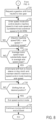
- FIG. 4 a prophetic vehicle operating sequence according to the method of FIGS. 7 and 8 is shown.
- the method of FIG. 4 is a method that may be performed when the axle gearbox includes synchronizers and does not include friction clutches.
- the vehicle operating sequence shown in FIG. 4 may be provided via the method of FIGS. 7 and 8 in cooperation with the system shown in FIG. 1 .
- the vertical lines at t 0 -t 4 represent times of interest during the sequence.
- the sequence of FIG. 4 takes place when an accelerator pedal is applied by a driver such that the wheel torque request is non-zero and while the vehicle is moving on a road.
- Plot 400 includes a vertical axis and a horizontal axis.
- the vertical axis represents speed and speed increases in the direction of the vertical axis arrow. Speed at the level of the horizontal axis is zero.
- the horizontal axis represents time and time increases from the left side of the plot to the right side of the plot.
- Dashed line 406 represents a speed of shaft 224 of an axle gearbox and solid line 402 represents a speed of shaft 220 multiplied by the gear ratio of the gear to be or being engaged (e.g., the gear ratio between shaft 202 and shaft 224 when low gear 208 is going to be or is being engaged).
- Dashed-dot line 408 represents an upper threshold speed difference between speed of shaft 224 and speed of shaft 220 multiplied by the ratio of the gear to be engaged. Dashed-dot line 408 may also be referred to as an over-shoot speed.
- Dashed-dot line 404 represents a lower threshold speed difference between speed of shaft 224 and speed of shaft 220 multiplied by the ratio of the gear to be engaged.
- the speed of shaft 224 is increasing and speed of shaft 220 multiplied by the ratio of the gear to be engaged (e.g., the ratio of the low range gear 208 ) is low.
- the axle gearbox may be in a neutral position at this time (not shown).
- speed of electric machine 126 begins increasing, thereby increasing the speed of shaft 220 multiplied by the ratio of the gear to be engaged in response to a request to shift the axle gearbox from neutral to a gear (high range or low range).
- the electric machine 126 is operating in a speed control mode (e.g., a mode where a speed of the electric machine 126 is controlled to a desired or requested speed while torque output of electric machine 126 is increased or decreased to match speed of the electric machine to the desired or requested speed) and the electric machine is commanded to the speed of line 408 .
- the speed of the electric machine 126 and speed of shaft 220 multiplied by the gear ratio of the gear to be engaged increases between time t 1 and time t 2 .
- the speed of shaft 224 continues to increase.
- the speed of shaft 220 multiplied by the gear ratio to be engaged exceeds threshold 408 and the machine now exits speed model and enters torque mode. Therefore, torque of the electric machine 126 is reduced to zero and the electric machine begins to free-wheel (e.g., rotate without producing torque via the electric machine or without absorbing driveline torque via the electric machine).
- the shift fork is commanded to move the synchronizers 216 and gear engagement collar 217 in gear (low range gear 208 or high range gear 218 ).
- the speed of shaft 224 continues to increase.
- the initial engagement happens between the gear engagement collar and the gear (low range or high range).
- the synchronizers 216 engage the gear (low or high) and reduce the speed difference between the gear engagement collar 217 and the gear (low or high) so that speed of shaft 220 multiplied by the gear ratio (low or high) converges to the speed of shaft 224 .
- the engagement completes.
- the electric machine 126 is in a torque control mode.
- the gear engagement collar 217 locks the gear (high or low) to shaft 220 so that the speed of shaft 220 multiplied by the ratio of gear (low or high) is equal to the speed of shaft 224 .
- the torque of the electric machine is ramped to the driver demand torque.
- the electric machine may be controlled in a speed control mode to reduce the speed difference between the axle gearbox shafts.
- the shift forks may be moved without fighting the electric machine output via ceasing to supply electric power to the electric machine. Once the shift forks engage the new gear, the electric machine may be activated in a torque control mode to meet driver demand.
- FIG. 5 a second prophetic vehicle operating sequence according to the method of FIGS. 7 and 8 is shown.
- the method of FIG. 5 is a method that may be performed when the axle gearbox does not include synchronizers or friction clutches.
- the vehicle operating sequence shown in FIG. 5 may be provided via the method of FIGS. 7 and 8 in cooperation with the system shown in FIG. 1 .
- the vertical lines at t 10 -t 14 represent times of interest during the sequence.
- the sequence of FIG. 5 takes place when an accelerator pedal is applied by a driver such that the wheel torque request is non-zero and while the vehicle is moving on a road.
- Plot 500 includes a vertical axis and a horizontal axis.
- the vertical axis represents speed and speed increases in the direction of the vertical axis arrow. Speed at the level of the horizontal axis is zero.
- the horizontal axis represents time and time increases from the left side of the plot to the right side of the plot.
- Dashed line 506 represents a speed of shaft 224 of an axle gearbox and solid line 502 represents a speed of shaft 220 multiplied by the gear ratio of the gear to be or being engaged (e.g., the gear ratio between shaft 202 and shaft 224 when low gear 208 is going to be or is being engaged).
- Dashed-dot line 508 represents an upper threshold speed difference between speed of shaft 224 and speed of shaft 220 multiplied by the ratio of the gear to be engaged. Dashed-dot line 508 may also be referred to as an over-shoot speed.
- Dashed-dot line 504 represents a lower threshold speed difference between speed of shaft 224 and speed of shaft 220 multiplied by the ratio of the gear to be engaged.
- the speed of shaft 224 is increasing and speed of shaft 220 multiplied by the ratio of the gear to be engaged (e.g., the ratio of the low range gear 208 ) is low.
- the axle gearbox may be in a neutral position at this time (not shown).
- speed of electric machine 126 begins increasing, thereby increasing the speed of shaft 220 multiplied by the ratio of the gear to be engaged in response to a request to shift the axle gearbox from neutral to a lower gear ratio.
- the electric machine 126 is operating in a speed control mode and its speed is commanded to the speed represented by line 508 .
- the speed of the electric machine 126 and speed of shaft 220 multiplied by the gear ratio of the gear to be engaged increases between time t 11 and time t 12 .
- the speed of shaft 224 continues to increase.
- the speed of shaft 220 multiplied by the gear ratio to be engaged settles to the desired speed difference.
- the speed difference between threshold 508 and shaft speed 506 is less than the speed difference between threshold 408 and shaft speed 406 shown in FIG. 4 because axle gearbox 177 does not include synchronizers so a smaller speed difference between shaft speed 506 and threshold speed 508 is tolerated.
- the electric machine remains in speed control mode and speed of the electric machine is commanded to maintain the desired speed difference.
- the speed of shaft 224 continues to increase.
- the speed of shaft 220 multiplied by the gear ratio to be engaged follows the speed to maintain the desired tracking to the speed of shaft 224 and the fork is commanded to move.
- the electric machine remains in speed control mode and the speed of shaft 224 has continued to increase since time t 12 .
- the electric machine exits speed control model and enters torque control mode before the engagement happens between the sliding sleeve or dog clutch and the desired gear (low range or high range).
- the first engagement between the sliding sleeve and the gear (low or high) happens.
- the engagement completes and the speed of shaft 220 multiplied by the desired gear ratio (low or high) converges to the speed of shaft 224 .
- the electric machine 126 is in a torque control mode.
- the a sliding sleeve or dog clutch 319 locks the desired gear (low or high) to shaft 220 so that the speed of shaft 220 multiplied by the ratio of desired gear (low or high) is equal to the speed of shaft 224 .
- the torque of the electric machine is ramped to the driver demand torque.
- the electric machine may be controlled in a speed control mode until the shift forks begin to move the sliding sleeve or dog clutch toward the gear being engaged or until the sliding sleeve or dog clutch engages the gear being engaged. Operating the electric machine in the speed control mode reduces the possibility of engagement interference during shifting of the axle gearbox.
- FIG. 6 a prophetic vehicle operating sequence according to the method of FIGS. 7 and 8 is shown.
- the vehicle operating sequence shown in FIG. 6 may be provided via the method of FIGS. 7 and 8 in cooperation with the system shown in FIG. 1 .
- the vertical lines at t 20 -t 24 represent times of interest during the sequence.
- the sequence of FIG. 6 takes place when an accelerator pedal is applied by a driver such that the wheel torque request is non-zero and while the vehicle is moving on a road.
- the first plot from the top of FIG. 6 is a plot of speed versus time.
- the vertical axis represents speed and speed increases in the direction of the vertical axis arrow.
- the horizontal axis represents time and time increases from the left side of the figure to the right side of the figure.
- Trace 602 represents the speed of shaft 224 .
- Trace 604 represents the speed of shaft 220 multiplied by the ratio of the gear being or about to be engaged.
- the second plot from the top of FIG. 6 is a plot of sequence states versus time.
- the vertical axis represents states of the sequence.
- the horizontal axis represents time and time increases from the left side of the figure to the right side of the figure.
- Line 206 represents the different states of the sequence.
- the third plot from the top of FIG. 6 is a plot of electric machine torque versus time.
- the vertical axis represents electric machine torque and electric machine torque increases in the direction of the vertical axis arrow.
- the horizontal axis represents time and time increases from the left side of the figure to the right side of the figure.
- Trace 808 represents the electric machine torque.
- speed of shaft 224 is at a middle level and increasing.
- Speed of shaft 220 multiplied by the ratio of the gear about to be engaged is low and the axle gearbox is in a neutral state (not shown).
- the electric machine torque is zero.
- a request to change the axle ratio to a gear range is made.
- the axle changes into a speed synchronization state where speed of shaft 220 multiplied by the ratio of the gear about to be engaged is commanded to the speed of shaft 224 .
- the electric machine is operated in a speed control mode.
- the electric machine torque output is increased to increase the speed of shaft 220 .
- the speed of shaft 220 multiplied by the ratio of the gear that is about to be engaged begins to increase.
- the speed of shaft 224 continues to increase.
- the speed of shaft 220 multiplied by the ratio of the gear that is about to be engaged exceeds a speed threshold and it is greater than the speed of shaft 224 . Therefore, the electric machine torque is reduced to bring the speed of shaft 220 multiplied by the ratio of the gear that is about to be engaged toward the speed of shaft 224 .
- the axle mode changes from speed control to torque control.
- the speed of shaft 224 continues to increase.
- the torque of electric machine 126 is reduced to zero so the shift forks begin to move the sleeve 319 toward the gear that is being engaged.
- the axle enters into a connect mode where shaft 220 is coupled to shaft 224 via engaging a gear.
- the sleeve 319 fully engages the gear being engaged (e.g., the low range gear) to shaft 220 , thereby coupling shaft 224 to shaft 220 .
- the electric machine torque is increased to provide the requested driver demand torque.
- the range gear (low or high) fully engages so that the speed of shaft 220 multiplied by the ratio of the engaged gear is equal to the speed of shaft 224 .
- the electric machine is operated in a torque control mode (e.g., a mode where electric machine speed may vary while electric machine torque meets or follows a requested electric machine torque) and commanded to provide the driver demand torque.
- FIGS. 7 and 8 an example method for operating a vehicle that includes an axle with a gearbox is shown.
- the axle may be of the type shown in FIG. 1 .
- the method of FIGS. 7 and 8 may be incorporated into and may cooperate with the system of FIG. 1 . Further, at least portions of the method of FIGS. 7 and 8 may be incorporated as executable instructions stored in non-transitory memory while other portions of the method may be performed via a controller transforming operating states of devices and actuators in the physical world.
- the method of FIGS. 7 and 8 may be entered when the electric machine (e.g., 126 is operating in a torque mode and following driver demand torque).
- method 700 judges if there is a request to change gear ratios of the axle gearbox.
- a request to change gear ratios of the axle gearbox may be generated via a human and a human/machine interface. Alternatively, an autonomous driver may request a gear ratio change of the axle gearbox. If method 700 judges that there is a request to change gear ratios of the axle gearbox (e.g., a request to change from a high gear to a low gear or vice-versa), the answer is yes and method 700 proceeds to 702 . Otherwise, the answer is no and method 700 proceeds to 750 .
- method 700 maintains the present operating state of the axle gearbox.
- the axle gearbox may remain engaged in a low gear, engaged in a high gear, or in neutral. Method 700 proceeds to exit.
- method 700 judges if gear synchronizers are not present or if gear synchronizers are degraded. If so, the answer is yes and method 700 proceeds to 720 . Otherwise, the answer is no and method 700 proceeds to 704 .
- method 700 requests shifting to a gear from neutral via adjusting a position of the shift forks to disengage a presently engaged gear.
- the new gear is a low range gear or low gear and the presently engaged gear is a high range gear or high gear.
- the new gear is a high range gear or high gear and the presently engaged gear is a low range gear or low gear.
- Method 700 proceeds to 706 .
- method 700 exits a torque control mode for electric machine 126 and operates electric machine 126 in a speed control mode.
- Method 700 commands electric machine 126 to a speed such that electric machine rotates a shaft that supports gear engagement collar 217 (e.g., shaft 220 ) at a speed that when multiplied by the gear ratio between the shaft that supports gear engagement collar 217 and the axle gearbox output shaft (e.g., 224 ) is equal to the axle gearbox output shaft speed (e.g., speed of shaft 224 ) plus an overshoot or threshold speed.
- gear engagement collar 217 e.g., shaft 220
- the axle gearbox output shaft e.g., 224
- the speed of the electric machine 126 may be different than the speed of the shaft supporting gear engagement collar 217 due to any gearing that may be between the electric machine 126 and shaft 220 that supports the gear engagement collar 217 .
- speed of the electric machine is adjusted such that speed of the shaft that supports gear engagement collar 217 may be adjusted to a speed of 450 RPM divided by a gear ratio between the shaft that supports gear engagement collar 217 and the output shaft, the gear ratio including the gear being engaged.
- Method 700 proceeds to 708 .
- method 700 judges if the speed of the shaft that supports gear engagement collar 217 multiplied by the gear ratio (GR) being engaged between the shaft that supports gear engagement collar 217 and the output shaft 224 minus speed of output shaft 224 is greater than or equal to an overshoot speed (e.g., 50 RPM), if so the answer is yes and method 700 proceeds to 710 . Otherwise, the answer is no and method 700 returns to 706 .
- GR gear ratio
- method 700 exits the electric machine 126 from speed control mode and reduces electric machine torque to zero.
- the torque of electric machine 126 may be reduced to zero in a threshold amount of time.
- Method ceases supplying electric power to electric machine 126 and the electric machine begins to free-wheel.
- Method 700 proceeds to 712 .
- method 700 moves the shift fork 212 to engage the requested gear.
- the shift fork moves the gear engagement collar 217 and the synchronizers 216 so that the synchronizers 216 engage the gear 208 or gear 218 .
- Method 700 proceeds to 714 .
- method 700 begins supplying electric current to electric machine 126 when the shift fork 212 reaches an end of travel and the requested gear is fully engaged.
- the torque of the electric machine 126 is adjusted so that the requested driver demand torque is delivered.
- electric current delivery to electric machine 126 may be delayed until the gear is fully engaged so that torque exchanged between the gear being engaged and the gear shift collar may be reduced to reduce the possibility of gearbox degradation.
- Method 700 proceeds to exit.
- method 700 requests shifting to gear from neutral via adjusting a position of the shift forks to disengage a presently engaged gear.
- the new gear is a low range gear or low gear and the presently engaged gear is a high range gear or high gear.
- the new gear is a high range gear or high gear and the presently engaged gear is a low range gear or low gear.
- Method 700 proceeds to 722 .
- method 700 exits a torque control mode for electric machine 126 and operates electric machine 126 in a speed control mode.
- Method 700 commands electric machine 126 to a speed such that electric machine rotates a shaft that supports gear engagement collar 217 (e.g., shaft 220 ) at a speed that when multiplied by the gear ratio between the shaft that supports gear engagement collar 217 and the axle gearbox output shaft (e.g., 224 ) is equal to the axle gearbox output shaft speed (e.g., speed of shaft 224 ) plus a predetermined overshoot or threshold speed (e.g., 5-30 RPM).
- a predetermined overshoot or threshold speed e.g., 5-30 RPM
- the speed of the electric machine 126 may be different than the speed of the shaft supporting sleeve 319 due to any gearing that may be between the electric machine 126 and shaft 220 that supports the sleeve 319 .
- speed of the electric machine is adjusted such that speed of the shaft that supports sleeve 319 may be adjusted to a speed of 410 RPM divided by a gear ratio between the shaft that supports sleeve 319 and the output shaft, the gear ratio including the gear being engaged.
- Method 700 proceeds to 724 .
- method 700 judges if the speed of the shaft that supports sleeve 319 multiplied by the gear ratio (GR) being engaged between the shaft that supports sleeve 319 and the output shaft 224 minus speed of output shaft 224 is greater than or equal to an overshoot speed (e.g., 10 RPM), if so the answer is yes and method 700 proceeds to 726 . Otherwise, the answer is no and method 700 returns to 722 .
- GR gear ratio
- method 700 judges if the average speed of the shaft that supports sleeve 319 multiplied by the gear ratio being engaged between the shaft that supports sleeve 319 and output shaft 244 is substantially equal to the average speed of output shaft 244 (e.g., the speeds are within 5% of each other). If so, the answer is yes and method 700 proceeds to 728 . Otherwise, the answer is no and method 700 returns to 726 .
- method 700 moves or commands the shift fork 212 to move the sleeve or dog clutch 319 to engage the requested gear while continuing to operate electric machine 126 in a speed control mode such that speed of shaft 220 multiplied by the gear ratio being engaged between the shaft 220 and shaft 224 is within the overshoot speed of the speed of shaft 224 .
- Method 700 proceeds to 730 .
- method 700 judges if the shifting fork 212 is in a desired position.
- the desired position may be a position that is greater than 95% of an air gap distance.
- the desired position may be an end of travel position. If method 700 judges that shifting fork 212 is in a desired position, the answer is yes and method 700 proceeds to 732 . Otherwise, the answer is no and method 700 returns to 730 .
- method 700 exits the electric machine 126 from speed control mode and enters the electric machine into torque control mode. Method 700 proceeds to 734 .
- method 700 continues to move the shift fork to an end of travel position if the shift fork is not at an end of travel position. At the end of travel the torque of the electric machine is increased to meet driver demand. Method 700 proceeds to exit.
- an electric machine may be operated in a speed control mode so that torque exchanged between an output shaft 224 of an axle gearbox and a shaft that includes a gear locking mechanism may be reduced during a gear shift.
- the gear shift may be performed with an axle gearbox that includes synchronizers or with an axle gearbox that does not include synchronizers.
- the method of FIGS. 7 and 8 provides for a method for operating a driveline, comprising: while an axle is rotating a gear of an axle gearbox that does not include a friction clutch, adjusting a speed of an electric machine such that a speed of a first shaft multiplied by a ratio of a gear between the first shaft and a second shaft is a threshold speed amount greater than a speed of the second shaft; reducing an amount of electric power supplied to the electric machine in response to the speed of the first shaft multiplied by the ratio of the gear between the first shaft and the second shaft being the threshold speed amount greater than the speed of the second shaft; and adjusting a position of a shift fork in response to reducing electric power supplied to the electric machine.
- the method includes where reducing the amount of electric power supplied to the electric machine includes ceasing to supply electric power to the electric machine, where the second shaft is an output shaft of the axle gearbox, where the electric machine is coupled to the first shaft, and where the first shaft supports a gear engagement collar.
- the method includes where adjusting the position of the shift fork in response to reducing electric power supplied to the electric machine includes adjusting the position of the shift fork in response to ceasing to supply electric power to the electric machine.
- the method includes where a synchronizer is coupled to the shift fork.
- the method further comprises increasing torque of the electric machine in response to the shift fork reaching an end of travel position.
- the method includes where the axle gearbox is coupled to a differential of the axle.
- the method includes where the electric machine is coupled to the axle gearbox.
- the method of FIGS. 7 and 8 also provides for a method for operating a driveline, comprising: while an axle is rotating a gear of an axle gearbox that does not include a friction clutch, adjusting a speed of an electric machine such that a speed of a first shaft multiplied by a ratio of a gear between the first shaft and a second shaft is a threshold speed amount greater than a speed of the second shaft, the first shaft and the second shaft included in the axle gearbox; and adjusting a position of a shift fork in response to an average speed slope of the first shaft multiplied by the ratio of the gear between the first shaft and the second shaft being substantially equal to an average speed slope of the second shaft.
- the method includes where the electric machine is operated in a speed control mode while adjusting the speed of the electric machine, where the second shaft is an output shaft of the axle gearbox, where the electric machine is coupled to the first shaft, and where the first shaft supports a gear engagement collar.
- the method further comprises exiting the speed control mode and entering the electric machine into a torque control mode in response to the shifting fork being at a desired position.
- the method further comprises continuing to move the shift fork to an end of travel position.
- the method includes where the axle gearbox is coupled to a differential.
- the method of FIGS. 7 and 8 provides for a method for operating a driveline, comprising: while an axle is rotating a gear of an axle gearbox that does not include a friction clutch, shifting gears of an axle gearbox via operating an electric machine in a speed control mode and adjusting a position of a shift fork when a speed of a first axle gearbox multiplied by a ratio of a gear being engaged is within a threshold speed of a second axle.
- the method includes where the first shaft support a gear engagement collar.
- the method includes where the second shaft is an output shaft of the axle gearbox, and where the output shaft of the axle gearbox is coupled to a differential.
- control and estimation routines included herein can be used with various engine and/or vehicle system configurations.
- the control methods and routines disclosed herein may be stored as executable instructions in non-transitory memory and may be carried out by the control system including the controller in combination with the various sensors, actuators, and other engine hardware. Further, portions of the methods may be physical actions taken in the real world to change a state of a device.
- the specific routines described herein may represent one or more of any number of processing strategies such as event-driven, interrupt-driven, multi-tasking, multi-threading, and the like. As such, various actions, operations, and/or functions illustrated may be performed in the sequence illustrated, in parallel, or in some cases omitted.
- the order of processing is not necessarily required to achieve the features and advantages of the example examples described herein, but is provided for ease of illustration and description.
- One or more of the illustrated actions, operations and/or functions may be repeatedly performed depending on the particular strategy being used.
- the described actions, operations and/or functions may graphically represent code to be programmed into non-transitory memory of the computer readable storage medium in the engine control system, where the described actions are carried out by executing the instructions in a system including the various engine hardware components in combination with the electronic controller.
- One or more of the method steps described herein may be omitted if desired.
Landscapes
- Engineering & Computer Science (AREA)
- General Engineering & Computer Science (AREA)
- Mechanical Engineering (AREA)
- Power Engineering (AREA)
- Transportation (AREA)
- Control Of Transmission Device (AREA)
- Electric Propulsion And Braking For Vehicles (AREA)
Abstract
Description
Claims (18)
Priority Applications (3)
| Application Number | Priority Date | Filing Date | Title |
|---|---|---|---|
| US16/569,567 US11760211B2 (en) | 2019-09-12 | 2019-09-12 | System and method for changing gear ranges of an electric vehicle |
| CN202010952564.0A CN112483646A (en) | 2019-09-12 | 2020-09-11 | System and method for changing a range of an electric vehicle |
| DE102020123875.4A DE102020123875A1 (en) | 2019-09-12 | 2020-09-14 | SYSTEM AND PROCEDURE FOR CHANGING GEAR AREAS OF AN ELECTRIC VEHICLE |
Applications Claiming Priority (1)
| Application Number | Priority Date | Filing Date | Title |
|---|---|---|---|
| US16/569,567 US11760211B2 (en) | 2019-09-12 | 2019-09-12 | System and method for changing gear ranges of an electric vehicle |
Publications (2)
| Publication Number | Publication Date |
|---|---|
| US20210078412A1 US20210078412A1 (en) | 2021-03-18 |
| US11760211B2 true US11760211B2 (en) | 2023-09-19 |
Family
ID=74686306
Family Applications (1)
| Application Number | Title | Priority Date | Filing Date |
|---|---|---|---|
| US16/569,567 Active 2040-08-18 US11760211B2 (en) | 2019-09-12 | 2019-09-12 | System and method for changing gear ranges of an electric vehicle |
Country Status (3)
| Country | Link |
|---|---|
| US (1) | US11760211B2 (en) |
| CN (1) | CN112483646A (en) |
| DE (1) | DE102020123875A1 (en) |
Families Citing this family (4)
| Publication number | Priority date | Publication date | Assignee | Title |
|---|---|---|---|---|
| FR3129695A1 (en) * | 2021-11-29 | 2023-06-02 | Renault S.A.S | MODULAR ELECTRIC TRAIN FOR MOTOR VEHICLE |
| JP2023128013A (en) * | 2022-03-02 | 2023-09-14 | トヨタ自動車株式会社 | electric vehicle |
| CN114857255B (en) * | 2022-05-09 | 2024-05-17 | 潍柴动力股份有限公司 | AMT motor control method, AMT motor control device, electronic equipment, AMT motor control program and vehicle |
| US20240123967A1 (en) * | 2022-10-12 | 2024-04-18 | Caterpillar Inc. | Electric drive system for machine and electric drive control system for same |
Citations (17)
| Publication number | Priority date | Publication date | Assignee | Title |
|---|---|---|---|---|
| US5409432A (en) * | 1993-08-10 | 1995-04-25 | Eaton Corporation | Control system/method for engine brake assisted shifting |
| US6095947A (en) * | 1998-09-08 | 2000-08-01 | Eaton Corporation | Control for controller-assisted, manually shifted, synchronized, splitter-type compound transmissions |
| US6286379B1 (en) | 1999-05-07 | 2001-09-11 | Ford Global Technologies, Inc. | Method for shifting multi-speed axles |
| US20030096671A1 (en) | 2001-11-19 | 2003-05-22 | Visteon Global Technologies, Inc. | Electroncally controlled shift-on-the-go transmission |
| US20070278022A1 (en) * | 2006-05-02 | 2007-12-06 | Nissan Motor Co., Ltd. | Drive state shift control apparatus and method for vehicle |
| US20090118074A1 (en) * | 2007-11-06 | 2009-05-07 | Gm Global Technology Operations, Inc. | Method and apparatus to monitor rotational speeds in an electro-mechanical transmission |
| US20110174557A1 (en) * | 2008-04-17 | 2011-07-21 | Aisin Ai Co., Ltd. | Control system of hybrid power drive apparatus |
| WO2013058238A1 (en) * | 2011-10-17 | 2013-04-25 | Ntn株式会社 | Gear shift control method and gear shift control device for electric vehicle |
| US20140046559A1 (en) * | 2012-08-10 | 2014-02-13 | Yamaha Hatsudoki Kabushiki Kaisha | Vehicle |
| US20150057866A1 (en) * | 2013-08-23 | 2015-02-26 | Chyuan-Yow Tseng | Power Distribution Method for Electric Vehicle Driven by Two Power Sources |
| US9234565B2 (en) | 2012-05-31 | 2016-01-12 | Robert Bosch Gmbh | Two-speed transmission and electric vehicle |
| US9638302B2 (en) | 2012-07-13 | 2017-05-02 | Schaeffler Technologies Gmbh & Co. Kg | Electric axle with a two gear transmission |
| US9809098B2 (en) | 2015-11-04 | 2017-11-07 | Industrial Technology Research Institute | Two-speed transmission for electric vehicle |
| US9841092B2 (en) | 2010-12-23 | 2017-12-12 | Magna Powertrain Inc. | Multi-speed transaxle for electric and hybrid vehicle application |
| US20180162362A1 (en) * | 2016-12-12 | 2018-06-14 | Hyundai Motor Company | Shifting control method for hybrid vehicles |
| US10137775B2 (en) | 2016-10-21 | 2018-11-27 | Ford Global Technologies, Llc | Vehicle all-wheel drive control system |
| WO2020193697A1 (en) * | 2019-03-27 | 2020-10-01 | Vitesco Technologies Germany Gmbh | Method of controlling a dog clutch |
-
2019
- 2019-09-12 US US16/569,567 patent/US11760211B2/en active Active
-
2020
- 2020-09-11 CN CN202010952564.0A patent/CN112483646A/en active Pending
- 2020-09-14 DE DE102020123875.4A patent/DE102020123875A1/en active Pending
Patent Citations (17)
| Publication number | Priority date | Publication date | Assignee | Title |
|---|---|---|---|---|
| US5409432A (en) * | 1993-08-10 | 1995-04-25 | Eaton Corporation | Control system/method for engine brake assisted shifting |
| US6095947A (en) * | 1998-09-08 | 2000-08-01 | Eaton Corporation | Control for controller-assisted, manually shifted, synchronized, splitter-type compound transmissions |
| US6286379B1 (en) | 1999-05-07 | 2001-09-11 | Ford Global Technologies, Inc. | Method for shifting multi-speed axles |
| US20030096671A1 (en) | 2001-11-19 | 2003-05-22 | Visteon Global Technologies, Inc. | Electroncally controlled shift-on-the-go transmission |
| US20070278022A1 (en) * | 2006-05-02 | 2007-12-06 | Nissan Motor Co., Ltd. | Drive state shift control apparatus and method for vehicle |
| US20090118074A1 (en) * | 2007-11-06 | 2009-05-07 | Gm Global Technology Operations, Inc. | Method and apparatus to monitor rotational speeds in an electro-mechanical transmission |
| US20110174557A1 (en) * | 2008-04-17 | 2011-07-21 | Aisin Ai Co., Ltd. | Control system of hybrid power drive apparatus |
| US9841092B2 (en) | 2010-12-23 | 2017-12-12 | Magna Powertrain Inc. | Multi-speed transaxle for electric and hybrid vehicle application |
| WO2013058238A1 (en) * | 2011-10-17 | 2013-04-25 | Ntn株式会社 | Gear shift control method and gear shift control device for electric vehicle |
| US9234565B2 (en) | 2012-05-31 | 2016-01-12 | Robert Bosch Gmbh | Two-speed transmission and electric vehicle |
| US9638302B2 (en) | 2012-07-13 | 2017-05-02 | Schaeffler Technologies Gmbh & Co. Kg | Electric axle with a two gear transmission |
| US20140046559A1 (en) * | 2012-08-10 | 2014-02-13 | Yamaha Hatsudoki Kabushiki Kaisha | Vehicle |
| US20150057866A1 (en) * | 2013-08-23 | 2015-02-26 | Chyuan-Yow Tseng | Power Distribution Method for Electric Vehicle Driven by Two Power Sources |
| US9809098B2 (en) | 2015-11-04 | 2017-11-07 | Industrial Technology Research Institute | Two-speed transmission for electric vehicle |
| US10137775B2 (en) | 2016-10-21 | 2018-11-27 | Ford Global Technologies, Llc | Vehicle all-wheel drive control system |
| US20180162362A1 (en) * | 2016-12-12 | 2018-06-14 | Hyundai Motor Company | Shifting control method for hybrid vehicles |
| WO2020193697A1 (en) * | 2019-03-27 | 2020-10-01 | Vitesco Technologies Germany Gmbh | Method of controlling a dog clutch |
Also Published As
| Publication number | Publication date |
|---|---|
| DE102020123875A1 (en) | 2021-03-18 |
| US20210078412A1 (en) | 2021-03-18 |
| CN112483646A (en) | 2021-03-12 |
Similar Documents
| Publication | Publication Date | Title |
|---|---|---|
| US11760211B2 (en) | System and method for changing gear ranges of an electric vehicle | |
| US11046299B2 (en) | Methods and system for operating a four wheel drive electric vehicle | |
| US11364892B2 (en) | System and method for changing gear ranges of a four wheel drive vehicle | |
| US11493127B2 (en) | System and method for reducing gear lash related torque disturbances | |
| US11661066B2 (en) | Sand mode system and method for a vehicle | |
| US11167649B2 (en) | Methods and system for disconnecting an axle | |
| US11981199B2 (en) | Dig mode system and method for a vehicle | |
| CN112739569A (en) | Control of clutchless vehicular electronically shiftable transmission operating as a bi-directional power transfer device | |
| US11891042B2 (en) | System and method for characterizing a clutch | |
| WO2015076723A1 (en) | Method for controlling gear shifting in a hybrid driveline by use of an electric machine | |
| US20190217860A1 (en) | Vehicle and control apparatus | |
| US11499626B2 (en) | System and method for changing to a low gear range of a four wheel drive vehicle | |
| US11105380B2 (en) | Wheel end disconnect system and method | |
| US20230331234A1 (en) | Method for cold start lube evacuation | |
| US11987137B2 (en) | Drive axle system and method of control | |
| US20240140456A1 (en) | Method and system for vehicle performance control | |
| US11975707B2 (en) | Systems and methods for torque output control | |
| US20230099191A1 (en) | System and method for shifting a transmission | |
| US11815173B1 (en) | Method and system for transmission gear control | |
| US20210380114A1 (en) | Transmission unit for an electric vehicle and control method | |
| US11332138B2 (en) | Method of operating a powertrain system during coasting operation | |
| CN117227724A (en) | Torque control during transition to four-wheel drive in autopilot mode |
Legal Events
| Date | Code | Title | Description |
|---|---|---|---|
| AS | Assignment |
Owner name: FORD GLOBAL TECHNOLOGIES, LLC, MICHIGAN Free format text: ASSIGNMENT OF ASSIGNORS INTEREST;ASSIGNORS:MOUBARAK, PAUL M.;DIXIT, SHUBHAM;TORRES, JOSEPH JAY;SIGNING DATES FROM 20190815 TO 20190820;REEL/FRAME:050363/0469 |
|
| FEPP | Fee payment procedure |
Free format text: ENTITY STATUS SET TO UNDISCOUNTED (ORIGINAL EVENT CODE: BIG.); ENTITY STATUS OF PATENT OWNER: LARGE ENTITY |
|
| STPP | Information on status: patent application and granting procedure in general |
Free format text: DOCKETED NEW CASE - READY FOR EXAMINATION |
|
| STPP | Information on status: patent application and granting procedure in general |
Free format text: NON FINAL ACTION MAILED |
|
| STPP | Information on status: patent application and granting procedure in general |
Free format text: FINAL REJECTION MAILED |
|
| STPP | Information on status: patent application and granting procedure in general |
Free format text: DOCKETED NEW CASE - READY FOR EXAMINATION |
|
| STPP | Information on status: patent application and granting procedure in general |
Free format text: NON FINAL ACTION MAILED |
|
| STPP | Information on status: patent application and granting procedure in general |
Free format text: RESPONSE TO NON-FINAL OFFICE ACTION ENTERED AND FORWARDED TO EXAMINER |
|
| STPP | Information on status: patent application and granting procedure in general |
Free format text: FINAL REJECTION MAILED |
|
| STPP | Information on status: patent application and granting procedure in general |
Free format text: NOTICE OF ALLOWANCE MAILED -- APPLICATION RECEIVED IN OFFICE OF PUBLICATIONS |
|
| STPP | Information on status: patent application and granting procedure in general |
Free format text: PUBLICATIONS -- ISSUE FEE PAYMENT VERIFIED |
|
| STCF | Information on status: patent grant |
Free format text: PATENTED CASE |