US11759280B2 - Surgical instrumentation for fixation of cervical spine - Google Patents
Surgical instrumentation for fixation of cervical spine Download PDFInfo
- Publication number
- US11759280B2 US11759280B2 US17/164,145 US202117164145A US11759280B2 US 11759280 B2 US11759280 B2 US 11759280B2 US 202117164145 A US202117164145 A US 202117164145A US 11759280 B2 US11759280 B2 US 11759280B2
- Authority
- US
- United States
- Prior art keywords
- drill
- wire
- drill bit
- guide
- universal
- Prior art date
- Legal status (The legal status is an assumption and is not a legal conclusion. Google has not performed a legal analysis and makes no representation as to the accuracy of the status listed.)
- Active, expires
Links
Images


Classifications
-
- A—HUMAN NECESSITIES
- A61—MEDICAL OR VETERINARY SCIENCE; HYGIENE
- A61B—DIAGNOSIS; SURGERY; IDENTIFICATION
- A61B17/00—Surgical instruments, devices or methods, e.g. tourniquets
- A61B17/16—Bone cutting, breaking or removal means other than saws, e.g. Osteoclasts; Drills or chisels for bones; Trepans
- A61B17/1662—Bone cutting, breaking or removal means other than saws, e.g. Osteoclasts; Drills or chisels for bones; Trepans for particular parts of the body
- A61B17/1671—Bone cutting, breaking or removal means other than saws, e.g. Osteoclasts; Drills or chisels for bones; Trepans for particular parts of the body for the spine
-
- A—HUMAN NECESSITIES
- A61—MEDICAL OR VETERINARY SCIENCE; HYGIENE
- A61B—DIAGNOSIS; SURGERY; IDENTIFICATION
- A61B90/00—Instruments, implements or accessories specially adapted for surgery or diagnosis and not covered by any of the groups A61B1/00 - A61B50/00, e.g. for luxation treatment or for protecting wound edges
- A61B90/03—Automatic limiting or abutting means, e.g. for safety
-
- A—HUMAN NECESSITIES
- A61—MEDICAL OR VETERINARY SCIENCE; HYGIENE
- A61B—DIAGNOSIS; SURGERY; IDENTIFICATION
- A61B17/00—Surgical instruments, devices or methods, e.g. tourniquets
- A61B17/16—Bone cutting, breaking or removal means other than saws, e.g. Osteoclasts; Drills or chisels for bones; Trepans
- A61B17/1613—Component parts
- A61B17/1615—Drill bits, i.e. rotating tools extending from a handpiece to contact the worked material
- A61B17/1617—Drill bits, i.e. rotating tools extending from a handpiece to contact the worked material with mobile or detachable parts
-
- A—HUMAN NECESSITIES
- A61—MEDICAL OR VETERINARY SCIENCE; HYGIENE
- A61B—DIAGNOSIS; SURGERY; IDENTIFICATION
- A61B17/00—Surgical instruments, devices or methods, e.g. tourniquets
- A61B17/16—Bone cutting, breaking or removal means other than saws, e.g. Osteoclasts; Drills or chisels for bones; Trepans
- A61B17/1613—Component parts
- A61B17/1633—Sleeves, i.e. non-rotating parts surrounding the bit shaft, e.g. the sleeve forming a single unit with the bit shaft
-
- A—HUMAN NECESSITIES
- A61—MEDICAL OR VETERINARY SCIENCE; HYGIENE
- A61B—DIAGNOSIS; SURGERY; IDENTIFICATION
- A61B17/00—Surgical instruments, devices or methods, e.g. tourniquets
- A61B17/16—Bone cutting, breaking or removal means other than saws, e.g. Osteoclasts; Drills or chisels for bones; Trepans
- A61B17/1637—Hollow drills or saws producing a curved cut, e.g. cylindrical
-
- A—HUMAN NECESSITIES
- A61—MEDICAL OR VETERINARY SCIENCE; HYGIENE
- A61B—DIAGNOSIS; SURGERY; IDENTIFICATION
- A61B17/00—Surgical instruments, devices or methods, e.g. tourniquets
- A61B17/16—Bone cutting, breaking or removal means other than saws, e.g. Osteoclasts; Drills or chisels for bones; Trepans
- A61B17/1697—Bone cutting, breaking or removal means other than saws, e.g. Osteoclasts; Drills or chisels for bones; Trepans specially adapted for wire insertion
-
- A—HUMAN NECESSITIES
- A61—MEDICAL OR VETERINARY SCIENCE; HYGIENE
- A61B—DIAGNOSIS; SURGERY; IDENTIFICATION
- A61B17/00—Surgical instruments, devices or methods, e.g. tourniquets
- A61B17/16—Bone cutting, breaking or removal means other than saws, e.g. Osteoclasts; Drills or chisels for bones; Trepans
- A61B17/17—Guides or aligning means for drills, mills, pins or wires
- A61B17/1739—Guides or aligning means for drills, mills, pins or wires specially adapted for particular parts of the body
- A61B17/1757—Guides or aligning means for drills, mills, pins or wires specially adapted for particular parts of the body for the spine
-
- A—HUMAN NECESSITIES
- A61—MEDICAL OR VETERINARY SCIENCE; HYGIENE
- A61B—DIAGNOSIS; SURGERY; IDENTIFICATION
- A61B17/00—Surgical instruments, devices or methods, e.g. tourniquets
- A61B17/16—Bone cutting, breaking or removal means other than saws, e.g. Osteoclasts; Drills or chisels for bones; Trepans
- A61B17/17—Guides or aligning means for drills, mills, pins or wires
- A61B17/1796—Guides or aligning means for drills, mills, pins or wires for holes for sutures or flexible wires
-
- A—HUMAN NECESSITIES
- A61—MEDICAL OR VETERINARY SCIENCE; HYGIENE
- A61B—DIAGNOSIS; SURGERY; IDENTIFICATION
- A61B17/00—Surgical instruments, devices or methods, e.g. tourniquets
- A61B17/56—Surgical instruments or methods for treatment of bones or joints; Devices specially adapted therefor
- A61B17/58—Surgical instruments or methods for treatment of bones or joints; Devices specially adapted therefor for osteosynthesis, e.g. bone plates, screws, setting implements or the like
- A61B17/68—Internal fixation devices, including fasteners and spinal fixators, even if a part thereof projects from the skin
- A61B17/70—Spinal positioners or stabilisers ; Bone stabilisers comprising fluid filler in an implant
- A61B17/7074—Tools specially adapted for spinal fixation operations other than for bone removal or filler handling
- A61B17/7076—Tools specially adapted for spinal fixation operations other than for bone removal or filler handling for driving, positioning or assembling spinal clamps or bone anchors specially adapted for spinal fixation
- A61B17/7082—Tools specially adapted for spinal fixation operations other than for bone removal or filler handling for driving, positioning or assembling spinal clamps or bone anchors specially adapted for spinal fixation for driving, i.e. rotating, screws or screw parts specially adapted for spinal fixation, e.g. for driving polyaxial or tulip-headed screws
-
- A—HUMAN NECESSITIES
- A61—MEDICAL OR VETERINARY SCIENCE; HYGIENE
- A61B—DIAGNOSIS; SURGERY; IDENTIFICATION
- A61B17/00—Surgical instruments, devices or methods, e.g. tourniquets
- A61B17/56—Surgical instruments or methods for treatment of bones or joints; Devices specially adapted therefor
- A61B17/58—Surgical instruments or methods for treatment of bones or joints; Devices specially adapted therefor for osteosynthesis, e.g. bone plates, screws, setting implements or the like
- A61B17/68—Internal fixation devices, including fasteners and spinal fixators, even if a part thereof projects from the skin
- A61B17/70—Spinal positioners or stabilisers ; Bone stabilisers comprising fluid filler in an implant
- A61B17/7074—Tools specially adapted for spinal fixation operations other than for bone removal or filler handling
- A61B17/7092—Tools specially adapted for spinal fixation operations other than for bone removal or filler handling for checking pedicle hole has correct depth or has an intact wall
-
- A—HUMAN NECESSITIES
- A61—MEDICAL OR VETERINARY SCIENCE; HYGIENE
- A61B—DIAGNOSIS; SURGERY; IDENTIFICATION
- A61B17/00—Surgical instruments, devices or methods, e.g. tourniquets
- A61B17/56—Surgical instruments or methods for treatment of bones or joints; Devices specially adapted therefor
- A61B17/58—Surgical instruments or methods for treatment of bones or joints; Devices specially adapted therefor for osteosynthesis, e.g. bone plates, screws, setting implements or the like
- A61B17/68—Internal fixation devices, including fasteners and spinal fixators, even if a part thereof projects from the skin
- A61B17/84—Fasteners therefor or fasteners being internal fixation devices
- A61B17/846—Nails or pins, i.e. anchors without movable parts, holding by friction only, with or without structured surface
- A61B17/848—Kirschner wires, i.e. thin, long nails
-
- A—HUMAN NECESSITIES
- A61—MEDICAL OR VETERINARY SCIENCE; HYGIENE
- A61B—DIAGNOSIS; SURGERY; IDENTIFICATION
- A61B17/00—Surgical instruments, devices or methods, e.g. tourniquets
- A61B17/56—Surgical instruments or methods for treatment of bones or joints; Devices specially adapted therefor
- A61B17/58—Surgical instruments or methods for treatment of bones or joints; Devices specially adapted therefor for osteosynthesis, e.g. bone plates, screws, setting implements or the like
- A61B17/88—Osteosynthesis instruments; Methods or means for implanting or extracting internal or external fixation devices
- A61B17/8897—Guide wires or guide pins
-
- A—HUMAN NECESSITIES
- A61—MEDICAL OR VETERINARY SCIENCE; HYGIENE
- A61B—DIAGNOSIS; SURGERY; IDENTIFICATION
- A61B17/00—Surgical instruments, devices or methods, e.g. tourniquets
- A61B17/56—Surgical instruments or methods for treatment of bones or joints; Devices specially adapted therefor
- A61B17/58—Surgical instruments or methods for treatment of bones or joints; Devices specially adapted therefor for osteosynthesis, e.g. bone plates, screws, setting implements or the like
- A61B17/88—Osteosynthesis instruments; Methods or means for implanting or extracting internal or external fixation devices
- A61B17/92—Impactors or extractors, e.g. for removing intramedullary devices
-
- A—HUMAN NECESSITIES
- A61—MEDICAL OR VETERINARY SCIENCE; HYGIENE
- A61B—DIAGNOSIS; SURGERY; IDENTIFICATION
- A61B90/00—Instruments, implements or accessories specially adapted for surgery or diagnosis and not covered by any of the groups A61B1/00 - A61B50/00, e.g. for luxation treatment or for protecting wound edges
- A61B90/06—Measuring instruments not otherwise provided for
-
- A—HUMAN NECESSITIES
- A61—MEDICAL OR VETERINARY SCIENCE; HYGIENE
- A61B—DIAGNOSIS; SURGERY; IDENTIFICATION
- A61B90/00—Instruments, implements or accessories specially adapted for surgery or diagnosis and not covered by any of the groups A61B1/00 - A61B50/00, e.g. for luxation treatment or for protecting wound edges
- A61B90/03—Automatic limiting or abutting means, e.g. for safety
- A61B2090/033—Abutting means, stops, e.g. abutting on tissue or skin
- A61B2090/034—Abutting means, stops, e.g. abutting on tissue or skin abutting on parts of the device itself
-
- A—HUMAN NECESSITIES
- A61—MEDICAL OR VETERINARY SCIENCE; HYGIENE
- A61B—DIAGNOSIS; SURGERY; IDENTIFICATION
- A61B90/00—Instruments, implements or accessories specially adapted for surgery or diagnosis and not covered by any of the groups A61B1/00 - A61B50/00, e.g. for luxation treatment or for protecting wound edges
- A61B90/06—Measuring instruments not otherwise provided for
- A61B2090/062—Measuring instruments not otherwise provided for penetration depth
-
- A—HUMAN NECESSITIES
- A61—MEDICAL OR VETERINARY SCIENCE; HYGIENE
- A61B—DIAGNOSIS; SURGERY; IDENTIFICATION
- A61B90/00—Instruments, implements or accessories specially adapted for surgery or diagnosis and not covered by any of the groups A61B1/00 - A61B50/00, e.g. for luxation treatment or for protecting wound edges
- A61B90/08—Accessories or related features not otherwise provided for
- A61B2090/0801—Prevention of accidental cutting or pricking
- A61B2090/08021—Prevention of accidental cutting or pricking of the patient or his organs
Definitions
- the present disclosure relates generally to spinal fixation, and more specifically to surgical instruments used for fixation of the cervical spine.
- Spinal fusion is a procedure in which damaged vertebrae are removed, and vertebrae adjacent to the removed vertebrae are fused together with graft material.
- the spine must be immobilized during fusion.
- one or more fixation rods are anchored to the vertebrae to limit movement.
- Fixation rods are anchored to vertebrae using bone screws that are driven into the vertebrae.
- a hole is prepared in the vertebral body in a minimally invasive manner.
- a drill tube is passed through a small incision and navigated to a desired entry point on the vertebral body.
- a cortical punch is then advanced through the tube to punch a start hole in the cortical layer of bone.
- the cortical punch is then removed from the tube, and a drill bit is advanced through the tube to the start hole.
- the surgical drill is powered on to drill a hole of a desired diameter and depth. After the screw hole is drilled, the drill guide is removed, and a bone screw can be driven into the screw hole.
- control drill depth is to attach some type of drill stop on the drill tube to limit how far the tip of the drill bit extends past the end of drill tube in the patient. This option may be difficult to implement, however, if there are multiple drill bits and drill tubes of different sizes that must be accommodated.
- K-wire can be attached to a bone at a desired location to precisely navigate the drill bit and other instruments to that location.
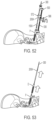
- FIG. 1 is a perspective view of a universal drill guide system according to one aspect of the present disclosure
- FIG. 2 is a front view of a set of drill tubes for use with the universal drill guide system of FIG. 1 ;
- FIG. 3 is a front view of a set of drill bits for use with the universal drill guide system of FIG. 1 ;
- FIG. 4 is a truncated perspective view of the universal drill guide system of FIG. 1 ;
- FIG. 5 is a truncated side view of the universal drill guide system of FIG. 1 , showing a spring loaded lock in a first state;
- FIG. 6 is a truncated side view of the universal drill guide system of FIG. 1 , showing the spring loaded lock in a second state;
- FIG. 7 is a truncated perspective view of a drill tube capture mechanism of the universal drill guide system of FIG. 1 , showing the drill tube capture mechanism in a first position;
- FIG. 8 is a truncated perspective view of the drill tube capture mechanism of the universal drill guide system of FIG. 1 , showing the drill tube capture mechanism in a second position;
- FIG. 9 A is a truncated perspective view of the drill tube capture mechanism of the universal drill guide system of FIG. 1 during a first step of inserting a drill tube;
- FIG. 9 B is a truncated perspective view of the drill tube capture mechanism of the universal drill guide system of FIG. 1 during a second step of inserting a drill tube;
- FIG. 9 C is a truncated perspective view of the drill tube capture mechanism of the universal drill guide system of FIG. 1 during a third step of inserting a drill tube;
- FIG. 9 D is a truncated perspective view of the drill tube capture mechanism of the universal drill guide system of FIG. 1 after a final step of inserting a drill tube;
- FIG. 10 is an enlarged truncated perspective view of the drill tube capture mechanism of the universal drill guide system of FIG. 1 in a locking orientation;
- FIG. 11 is an enlarged truncated perspective view of the drill tube capture mechanism of the universal drill guide system of FIG. 1 in a release orientation;
- FIG. 12 is an enlarged perspective view of components of the universal drill guide system of FIG. 1 , showing the components when the drill stop is in a position for engagement with a drill;
- FIG. 13 is an enlarged perspective view of components of the universal drill guide system of FIG. 1 , showing the components when the drill stop is in a position released from a drill;
- FIG. 14 is an truncated perspective view of the universal drill guide system of FIG. 1 , showing the universal drill guide system in a condition to be detached from a drill tube;
- FIG. 15 is another truncated perspective view of the universal drill guide system of FIG. 1 , showing the universal drill guide system being detached from the drill tube;
- FIG. 16 is a perspective view of a cannulated drill bit and K-wire according to another aspect of the present disclosure.
- FIG. 17 is an enlarged truncated view of a cannulated drill bit and K-wire according to another aspect of the present disclosure.
- FIG. 18 is an enlarged truncated cross section view of the cannulated drill bit and K-wire of FIG. 17 ;
- FIG. 19 is an enlarged perspective view of a cannulated drill bit according to another aspect of the present disclosure, showing a midsection of the drill bit;
- FIG. 20 is an enlarged perspective view of a component of a cannulated drill bit according to another aspect of the present disclosure.
- FIG. 21 is a truncated perspective view of a cannulated drill bit and K-wire according to another aspect of the present disclosure, with a force retention sleeve shown in a first position;
- FIG. 22 is a truncated perspective view of the cannulated drill bit and K-wire of FIG. 21 , with the force retention sleeve shown in a second position;
- FIG. 23 is an enlarged truncated perspective view of a cannulated drill bit according to another aspect of the present disclosure, with the cannulated drill bit attached to a drill driver;
- FIG. 24 is another enlarged truncated perspective view of the cannulated drill bit of FIG. 23 , with some features shown transparent for clarity;
- FIG. 25 is a perspective view of a drill removal tool according to another aspect of the present disclosure.
- FIG. 26 is a truncated perspective view of the drill removal tool of FIG. 25 during attachment to a cannulated drill bit and K-wire;
- FIG. 27 is a truncated side view of a wire clamp according to another aspect of the present disclosure, showing the wire clamp in an unclamped state;
- FIG. 28 is a truncated side view of the wire clamp of FIG. 27 , showing the wire clamp in a clamped state;
- FIG. 29 is an enlarged truncated cross section view of the wire clamp of FIG. 27 ;
- FIG. 30 is a truncated perspective view of components of the drill removal tool of FIG. 25 ;
- FIG. 31 is another truncated perspective view of components of the drill removal tool of FIG. 25 ;
- FIG. 32 is another truncated perspective view of the drill removal tool of FIG. 25 , shown during removal of the drill bit from the patient;
- FIG. 33 is a perspective view of a bone screw driver with K-wire retention module according to another aspect of the present disclosure, with the bone screw driver and K-wire retention module passed over a K-wire;
- FIG. 34 is an enlarged truncated side view of a distal end of the bone screw driver of FIG. 33 ;
- FIG. 35 is an enlarged truncated perspective view of the distal end of the bone screw driver of FIG. 33 ;
- FIG. 36 is another perspective view of the bone screw driver with K-wire retention module of FIG. 33 during advancement over a K-wire;
- FIG. 37 is an enlarged truncated perspective view of the bone screw driver with K-wire retention module of FIG. 33 , showing internal components of the K-wire retention module;
- FIG. 38 is a side view of the K-wire retention module of FIG. 33 , with some components removed for clarity, the K-wire retention module shown in a first mode of operation;
- FIG. 39 is an enlarged truncated perspective view of the K-wire retention module components of FIG. 38 in the first mode of operation;
- FIG. 40 is a side view of the K-wire retention module of FIG. 33 , with some components removed for clarity, the K-wire retention module shown in a second mode of operation;
- FIG. 41 is an enlarged truncated perspective view of the K-wire retention module components of FIG. 40 in the second mode of operation;
- FIG. 42 is a perspective view of an alternate bone screw driver with K-wire retention module according to another aspect of the present disclosure, with the bone screw driver and K-wire retention module passed over a K-wire;
- FIG. 43 is a perspective view of the bone screw driver with K-wire retention module of FIG. 42 , showing internal components of the K-wire retention module in a first mode of operation;
- FIG. 44 is an enlarged perspective view of the internal components of the K-wire retention module of FIG. 43 in the first mode of operation;
- FIG. 45 is an enlarged perspective view of the internal components of the K-wire retention module of FIG. 43 in a second mode of operation;
- FIG. 46 is an enlarged truncated perspective view of the drill removal tool of FIG. 25 , showing one step of an alternate technique for using the drill removal tool;
- FIG. 47 is another enlarged truncated perspective view of the drill removal tool of FIG. 25 , showing another step of the alternate technique;
- FIG. 48 is another truncated perspective view of the drill removal tool of FIG. 25 , showing another step of the alternate technique;
- FIG. 49 is another truncated perspective view of the drill removal tool of FIG. 25 , showing another step of the alternate technique;
- FIG. 50 is another enlarged truncated perspective view of the drill removal tool of FIG. 25 , showing another step of the alternate technique;
- FIG. 51 is another enlarged truncated perspective view of the drill removal tool of FIG. 25 , showing another step of the alternate technique;
- FIG. 52 is another truncated perspective view of the drill removal tool of FIG. 25 , showing another step of the alternate technique.
- FIG. 53 is another truncated perspective view of the drill removal tool of FIG. 25 , showing another step of the alternate technique.
- Universal drill guide system 100 features a universal drill guide 110 .
- Universal drill guide 110 includes a tubular guide body 120 and a handle 130 that extends obliquely from the guide body.
- Guide body 120 has a proximal end 122 defining a proximal opening 123 for receiving a drill bit, as will be described.
- Guide body 120 also has a distal end 124 defining a distal opening 125 for receiving a drill tube, as will be described.
- guide body 120 features a drill stop 140 that limits drilling depth by limiting how far a drill bit is advanced through the guide body.
- An optional navigation star unit 50 is attached to universal drill guide 110 in FIG. 1 , which can be calibrated and used with conventional navigation systems.
- Universal drill guide system 100 also includes a set of interchangeable drill tubes 150 and a set of interchangeable drill bits 200 .
- the set of interchangeable drill tubes 150 includes a first drill tube 150 A, second drill tube 150 B, and third drill tube 150 C.
- the set of interchangeable drill bits 200 includes a first drill bit 200 A, a second drill bit 200 B and a third drill bit 200 C. All of the drill tubes 150 A, 150 B and 150 C, and all of the drill bits 200 A, 200 B and 200 C are connectable to universal drill guide 110 .
- First, second and third drill bits 200 A, 200 B and 200 C are cannulated and have features designed to retain a K-wire, as will be explained in the next section of this description.
- First, second and third drill bits 200 A, 200 B and 200 C also have different drilling diameters. Each drilling diameter is configured to drill a screw hole of a specific size into a vertebral body.
- First, second and third drill bits 200 A, 200 B and 200 C each have a proximal end 202 for attachment to a drill driver and an opposite distal end 204 with cutting edges to drill a hole.
- First, second and third drill bits 200 A, 200 B and 200 C also have a reduced diameter section 205 adjacent an enlarged diameter section 207 , forming an abrupt transition.
- Stop surfaces 206 cooperate with drill stop 140 on guide body 120 to limit how far the drill bits can be advanced into the vertebral body during drilling. Stop surfaces 206 also play a role in removing the drill bits 200 A, 200 B and 200 C after a drilling operation, as will be explained in another section.
- First, second and third drill tubes 150 A, 150 B and 150 C are designed to guide the advancement of first, second and third drill bits 200 A, 200 B and 200 C, respectively, during drilling. First, second and third drill tubes 150 A, 150 B and 150 C also keep first, second and third drill bits 200 A, 200 B and 200 C axially stable during drilling.
- Each of the first, second and third drill tubes 150 A, 150 B and 150 C has a proximal end 152 for attachment to guide body 120 and an opposite distal end 154 that is inserted into the patient at the drilling location.
- Proximal end 152 of each drill tube 150 A, 150 B and 150 C includes a notch 157 that facilitates attachment to guide body 120 , as will be described in more detail.
- First, second and third drill tubes 150 A, 150 B and 150 C define drill bit passages 156 having inner diameters specially sized to receive first, second and third drill bits 200 A, 200 B and 200 C, respectively.
- first, second and third drill bits 200 A, 200 B and 200 C are designed to only work with first, second and third drill tubes 150 A, 150 B and 150 C, respectively.
- Indicia are provided on each of first, second and third drill tubes 150 A, 150 B and 150 C, and each of first, second and third drill bits 200 A, 200 B and 200 C, to assist the user in selecting the proper drill tube for the selected drill bit. Any type of indicia can be used.
- first drill tube 150 A and first drill bit 200 A have matching indicia 160 A
- second drill tube 150 B and second drill bit 200 B have matching indicia 160 B
- third drill tube 150 C and first drill bit 200 C have matching indicia 160 C.
- Indicia 160 A, 160 B and 160 C are unique and different from one another, and appear in the form of different colored bands around the circumference of each drill tube and drill bit.
- drill stop 140 has a shaft 142 and a stop plate 144 extending laterally from the shaft.
- Stop plate 144 has a slot 146 having a slot dimension that is wide enough to permit passage of the distal sections of first, second and third drill bits 200 A, 200 B and 200 C through the stop plate. Slot 146 is smaller than the cross sectional dimension of stop surfaces 206 of first, second and third drill bits 200 A, 200 B and 200 C.
- stop plate 144 is configured to permit advancement of each of first, second and third drill bits 200 A, 200 B and 200 C through the stop plate up until their respective stop surfaces 206 abut the stop plate. At such time, the drill bit has reached the selected drill depth, and further advancement of the drill bit through guide body 120 is prevented.
- drill stop 140 can be raised or lowered to set a desired drilling depth setting.
- a spring loaded lock 126 releasably engages shaft 142 of drill stop 140 to lock and unlock the shaft.
- Shaft 142 has a series of circumferential grooves 143 in one side.
- Spring loaded lock 126 is configured to engage one of grooves 143 to lock the position of shaft 142 under a spring bias.
- Spring loaded lock 126 includes a release button 127 that can be pressed inwardly as shown in FIG. 5 . Pressing release button 127 inwardly disengages spring loaded lock 126 from shaft 142 so the shaft can be raised or lowered relative to guide body 120 to set the depth setting.
- release button 127 is released as shown in FIG. 6 to allow spring loaded lock 126 to engage shaft 142 under spring bias. Engagement of spring loaded lock 126 with shaft 142 locks the vertical position of the shaft relative to guide body 120 and fixes the depth setting.
- Universal drill guide 110 includes two sets of indicia on the exterior that provide the user with a visual indicator of the selected depth setting.
- a first set of indicia 128 include a vertical series of markings 128 a on the side of guide body 120 .
- a second set of indicia 148 include a vertical series of markings 148 a on shaft 142 .
- Each marking 128 a , 148 a is labeled with a unique number corresponding to a depth in millimeters or other unit of measure. Markings 128 a are oriented on a different side of universal drill guide 110 than markings 148 a . This placement of redundant markings on two different sides addresses situations where the surgeon can only see one side of universal drill guide 110 .
- Guide body 120 includes an auto drill tube capture 170 that allows each of first, second and third drill tubes 150 A, 150 B and 150 C to be connected to distal opening 125 in a quick-connect coupling.
- Auto drill tube capture 170 allows a user to insert one of the drill tubes 150 A, 150 B and 150 C into guide body 120 and lock it in place without touching any locking mechanisms on the guide body. The drill tube is simply inserted into distal opening 125 until it engages an automatic lock.
- Each of the drill tubes 150 A, 150 B and 150 C has a different inner diameter to accommodate one of the drill bits, as noted above. However, all of the drill tubes 150 A, 150 B and 150 C have the same outer dimensions that engage the drill stop 140 and auto drill tube capture 170 . Therefore, all of the drill tubes 150 A, 150 B and 150 C interact with the auto drill tube capture 170 the same way.
- auto drill tube capture 170 includes a spring loaded locking ring 172 inside guide body 120 .
- Locking ring 172 is configured to snap into notches 157 formed in each drill tube 150 A, 150 B and 150 C.
- Locking ring 172 is rotatable in the guide body between a locking orientation and a release orientation.
- a pair of compression springs 174 exert a counterclockwise biasing force on locking ring 172 to bias the locking ring in the locking orientation.
- Each compression spring 174 bears against a locking tab 176 that extends in a proximal direction or upwardly from the rest of locking ring 172 .
- Locking tabs 176 and compression springs 174 are captive in a pair of slots 178 .
- One end of each compression spring 174 bears against an end wall 179 of a slot 178 , and the opposite end of the spring bears against a locking tab 176 .
- the locking ring 172 is maintained in the locking orientation unless the user manually rotates the locking ring to the release orientation.
- Locking ring 172 can be rotated by exerting a clockwise force on a switch 173 that is attached to the locking ring.
- Switch 173 extends through an elongated aperture 121 in guide body 120 and is exposed on the exterior of the guide body.
- FIGS. 9 A- 9 D show a sequence in which a drill tube, in this example drill tube 150 A, is inserted into guide body 120 and locked in place by locking ring 172 . The same sequence occurs when drill tube 150 B and drill tube 150 C are inserted into guide body 120 .
- Drill tube 150 A is inserted through distal opening 125 and into a passage 129 formed in guide body 120 , as shown in FIG. 9 A .
- Locking ring 172 is initially disposed in the locking orientation. Drill tube 150 A is advanced into passage 129 until it enters locking ring 172 , as shown in FIG. 9 B . As drill tube 150 A continues to advance, the drill tube contacts an interior surface of locking ring 172 , as shown in FIG. 9 C . This contact between drill tube 150 A and locking ring 172 causes the locking ring to rotate out of the locking orientation. Contact with locking ring 172 occurs at a chamfer 177 on the locking ring that extends into passage 129 .
- the proximal end and sidewall of drill tube 150 A contact chamfer 177 as the drill tube is advanced proximally in the passage 129 .
- the orientation of the chamfer 177 is such that the side wall of the drill tube 150 A deflects the locking ring a small distance in a counterclockwise direction against the bias of the compression springs, storing additional energy in the springs. This deflection begins in FIG. 9 B and continues in FIG. 9 C .
- the locking ring 172 remains deflected until the notch 157 in the drill tube aligns with the chamfer 177 , shown in FIG. 9 D .
- the force deflecting the locking ring 172 is temporarily released, allowing the compression springs 174 to expand and return to their relaxed state. This expansion causes locking ring 172 to rotate back toward the locking orientation.
- Chamfer 177 snaps radially inwardly into the notch 157 under the bias of the compression springs 175 .
- the axial dimension of the locking ring 172 is substantially equal to the axial dimension of the slot 157 , such that the axial position of the drill tube is fixed and locked in the guide body 120 .
- FIG. 10 shows a cross section showing locking ring 172 in the locking orientation.
- the portion of the locking ring 172 that engages notch 157 is circled.
- FIG. 11 shows a cross section showing locking ring 172 in the release orientation. In this condition, no portion of locking ring 172 extends into notch 157 .
- drill tube 150 A can be removed from guide body 120 by rotating the switch 173 in the counterclockwise direction against the bias of the compression springs. This rotation moves the chamfer 177 out of the notch 157 , as shown in FIG. 11 . In this state, the drill tube is no longer axially restrained by the locking ring 172 and can be pulled out of the guide body 120 .
- Drill bits 200 A, 200 B and 200 C each have an outer diameter that corresponds to the inner diameter of drill tubes 150 A, 150 B and 150 C, respectively.
- Each of drill bits 200 A, 200 B and 200 C is long enough to extend from above drill stop 140 to beyond the distal end of the drill tube when the drill tube is attached to guide body 120 .
- the universal drill guide 110 includes a mechanism that pivots the drill stop 140 counterclockwise and away from the drill bit as the universal drill guide is released from the drill tube. This is accomplished with a camming mechanism 190 that interconnects the locking ring 172 with the shaft 142 of the drill stop 140 , as shown in FIGS. 12 and 13 .
- Locking ring 172 includes a cam slot 181 that drives a cam following pin 145 at the bottom of the shaft 142 .
- rotation of the locking ring 172 clockwise (or left in the Figures) causes the shaft 142 and drill stop 140 to simultaneously rotate counterclockwise (or right in the Figures), moving the drill stop 140 away from the drill bit so that the universal drill guide 110 can be lifted off of the drill tube while the drill tube and drill bit remain in the patient.
- the process of lifting universal drill guide 110 off of drill tube 150 A is illustrated in FIGS. 14 and 15 .
- First, second and third drill bits 200 A, 200 B and 200 C are cannulated and have features designed to retain a K-wire, as described previously.
- Drill bits 200 A, 200 B and 200 C are generally the same, but have a few differences.
- the outer diameters of drill bits 200 A, 200 B and 200 C are different, with each outer diameter configured to drill a hole of a different size.
- the inner diameter of drill bit 200 A is smaller than the inner diameters of drill bits 200 B and 200 C, with the inner diameter of drill bit 200 A configured to allow a K-wire having a diameter of 1.0 mm to pass through the bit.
- the inner diameters of drill bits 200 B and 200 C are larger, each configured to allow a K-wire having a diameter of 1.5 mm to pass through the bit.
- Drill bits 200 A, 200 B and 200 C also have different colored indicia on their exterior to assist the user in pairing each drill bit with its corresponding drill tube.
- Drill bit 200 A is shown with a K-wire 300 .
- K-wire 300 extends through a passage 208 that extends through drill bit 200 A from proximal end 202 to distal end 204 .
- K-wire 300 has a proximal end 302 , a distal end 304 and wire body 306 extending between the proximal and distal ends.
- Distal end 304 has a sharp pointed end 308 that can be punched into bone at a selected location. Once K-wire 300 is punched into the bone, a surgeon can pass a cannulated bone screw, drill bit, or other instrument over the K-wire and advance it to the selected location to perform an operation.
- K-wire 300 is significantly longer than drill bit 200 A. Therefore, K-wire 300 can extend through drill bit 200 A with proximal end 302 of the K-wire projecting proximally and outside of proximal end 202 of the drill bit. At the same time, K-wire 300 can extend through drill bit 200 A with distal end 304 of the K-wire projecting distally and outside of distal end 204 of the drill bit. K-wire 300 is releasably securable inside in drill bit 200 A as an assembly that allows the K-wire and drill bit to be drilled into a bone together.
- K-wire 300 is releasably secured to the inside of drill bit 200 A during drilling by a retention mechanism 290 that is built into the drill bit.
- Retention mechanism 290 is configured to engage K-wire 300 to prevent axial advancement of the K-wire relative to drill bit 200 A during drilling. This retention ensures that K-wire 300 and drill bit 200 A are inserted together and advance the same amount into bone.
- Retention mechanism 290 also allows torque applied to drill bit 200 A to be transferred to K-wire 300 .
- K-wire 300 and drill bit 200 A rotate in unison when the retention features are engaged.
- a torque driver can apply torque to K-wire 300 and drill bit 200 A in unison to plant the K-wire in the bone and form a pilot hole for a bone screw. Once the pilot hole is drilled, drill bit 200 A can be disengaged from K-wire 300 and removed from the patient while leaving the K-wire in the bone.
- Retention mechanism 290 includes a retention clip 292 configured to releasably engage with a locking groove 308 on an exterior portion of K-wire 300 .
- Locking grooves and retention clips according to the present disclosure can have various forms and geometries.
- the locking groove can extend around a portion of the K-wire, or completely surround the K-wire in a circumferential manner.
- the retention clip can be clipped onto the exterior of the drill bit, or be formed integrally with the drill bit.
- the retention clip can also have an inward-extending retention end that can be pressed into the locking groove to limit axial displacement of the K-wire in the drill bit.
- Retention clip 292 has a hub portion 294 that attaches the retention clip to drill bit 200 A.
- Retention clip 292 also has a retention end 296 opposite the hub portion 294 .
- Retention end 296 projects radially inwardly through a sidewall of drill bit 200 to engage locking groove 308 of K-wire 300 .
- K-wires according to the present disclosure can have a geometry in the locking groove that allows torque to be transferred from the drill bit/retention clip to the K-wire.
- the K-wire can have a flat surface on a portion of its exterior in the groove that engages a flat edge on the retention end of the retention clip.
- FIG. 19 shows an example of a K-wire 300 with a locking groove 308 that has a four-sided square-shaped section 310 in the groove.
- K-wire 300 can work with a retention clip formed in a drill bit according to any of the previous examples, such as drill bit 200 A.
- Locking grooves can be bounded by a proximal end wall and a distal end wall.
- the proximal and distal end walls can have different geometries that control axial displacement of the K-wire relative to the surrounding drill bit.
- locking groove 308 has a proximal end wall 312 and a distal end wall 314 .
- Distal end wall 314 is substantially perpendicular to a longitudinal axis 301 of K-wire 300 . This forms a stop 316 that can abut the retention end 296 of retention clip 292 when the retention clip is engaged in the locking groove 308 , thereby preventing relative displacement of K-wire 300 in the distal direction.
- the proximal end wall 312 consists of inclined surfaces 318 extending at an acute angle relative to axis 301 .
- the inclined surfaces 318 form a ramped section 320 that allows retention end 296 of retention clip 292 to gradually deflect outwardly and slide out of locking groove 308 during withdrawal of drill bit 200 A from the K-wire 300 after drilling is completed.
- Retention clip 292 is operable in a locked mode and a released mode.
- the locked mode the retention end 296 is pressed and held inwardly in the locking groove, as shown in FIG. 18 . This locks the axial position of K-wire 300 relative to the drill bit 200 during drilling. After drilling is complete, the inward force on the retention end 296 can be removed, leaving the retention clip 292 in the released mode.
- the released mode it is possible to move the drill bit 200 in a proximal direction relative to the K-wire 300 until the drill bit is completely removed from the K-wire. This allows drill bit 200 A to be withdrawn from a patient while leaving the K-wire 300 in the patient for further use.
- retention clip 292 has a partially-cylindrical hub portion 294 configured to clip onto the rounded exterior of a drill bit, similar to a pocket clip on a pen.
- Retention clip 292 also has a flexible arm 295 between hub portion 294 and a retention end 296 .
- Flexible arm 295 allows retention end 296 to flex radially outwardly under stored energy as the drill bit is withdrawn from the K-wire.
- the retention end 296 remains deflected in an outward position as the drill bit is removed from the K-wire. Once the drill bit is removed from the K-wire, the retention end 296 snaps back in the radially inward direction to its relaxed state shown in FIG. 20 .
- FIGS. 21 and 22 show another example of drill bit 200 ′ with a removable sleeve 298 ′.
- Sleeve 298 ′ is slidable over the exterior of drill bit 200 ′ between a first position and a second position. In the first position ( FIG. 21 ), sleeve 298 ′ covers retention end 296 ′ and applies inward force to it to hold retention clip 292 ′ in the engaged mode. In the second position ( FIG. 22 ), sleeve 298 ′ is moved off of retention end 296 ′, allowing the retention end to flex outwardly to permit disengagement of retention clip 298 ′ from the locking groove on a K-wire 300 .
- FIGS. 23 and 24 show an example in which a retention clip 292 of a drill bit 200 A is maintained in the engaged mode by a drill driver 400 .
- Drill driver 400 is clamped over retention end 296 of retention clip 292 and applies external force to maintain the retention clip in the engaged mode in a four-sided locking groove 308 of a K-wire 300 .
- Drill removal tool 500 is designed to remove a cannulated drill bit from bone after a hole is drilled, while leaving the K-wire in place in the bone. Once the drill bit is removed from the K-wire, a bone screw can be advanced over the K-wire and driven into the screw hole. Drill removal tool 500 can be used with any combination of drill bit, drill tube and K-wire. For purposes of this description, drill removal tool 500 will be described in use with the same drill bit 200 A, drill tube 150 A and K-wire 300 described previously.
- Drill removal tool 500 includes a first support end 510 , a second support end 520 and a toothed rack 530 extending between the first support end and second support end.
- First support end 510 includes a wire clamp 540 operable to clamp onto K-wire 300 .
- Second support end 520 include a C-shaped base 522 configured to fit snugly around drill tube 150 A.
- a drill bit remover 570 is axially displaceable on toothed rack 530 between first support end 510 and second support end 520 .
- wire clamp 540 is configured to be passed over the exposed end of K-wire 300 in an unlocked state, and subsequently clamp the K-wire in a locked state.
- Clamp 540 includes a hollow housing 542 which extends from first support end 510 .
- Housing 542 defines a clamp passage 544 having a proximal end 546 , distal end 548 and a converging section 549 between the proximal and distal ends.
- Proximal end 546 has an internal thread 547 .
- a knob 550 includes a dial 552 and shaft 554 with an external thread 557 that mates with internal thread 547 in clamp passage 544 .
- Knob 550 defines a through bore 558 that axially receives a clamping pin 560 .
- Clamping pin 560 defines a through passage 562 and wedge shaped collet 564 at its distal end 566 .
- Collet 564 has an outer diameter that gradually decreases toward distal end 566 , forming a cone-shaped projection that conforms to the shape of converging section 549 .
- Through passage 562 has an inner diameter adapted to receive K-wire 300 .
- Knob 550 is rotatable about a knob axis 551 between the unlocked state and the locked state. Knob axis 551 aligns coaxially with through bore 558 and through passage 562 .
- FIG. 27 shows knob 550 in the unlocked state
- FIG. 28 shows the knob after it is rotated to the locked state.
- Internal thread 547 and external thread 557 promote axial displacement of knob 550 when the knob is rotated.
- Clamping pin 560 is axially fixed in knob 550 , with the distal end 556 of the knob abutting collet 564 . In this arrangement, knob 550 and clamping pin 560 move axially and in unison in clamp housing 544 when the knob is rotated.
- Internal and external threads 547 , 557 are oriented so that rotation of dial 552 in a clockwise direction CW causes knob 550 and collet 560 to move distally into converging section 549 .
- the tapered shape of converging section 549 exerts inward force on collet 564 as clamping pin 560 moves distally, compressing the collet 564 so that it locks against K-wire 300 in a locked state.
- Drill removal tool 500 is attachable over K-wire 300 , drill bit 200 A and drill tube in two steps.
- wire clamp 540 is passed over K-wire.
- knob 550 is rotated counterclockwise to the unlocked state so that collet 564 is not compressed in converging section 549 of clamp passage 544 .
- second support end 520 and C-shaped base 522 are pivoted toward drill tube 150 A in the direction shown by the curved arrow in FIG. 26 .
- C-shaped base 522 is pivoted until the opening 523 in C-shaped base receives drill tube 150 A in a snug fit.
- drill bit remover 570 includes a fork-shaped anvil 572 that defines a through slot 574 .
- Through slot 574 aligns with clamp passage 544 and opening 523 , forming a straight passage through all three parts of drill removal tool 500 .
- Anvil 572 has a flat fork-lift surface 576 above through slot 574 .
- Through slot 574 and fork-lift surface 576 are configured to engage drill bit 200 A beneath stop surface 206 , as mentioned earlier.
- Through slot 574 has a rounded end 575 with a diameter that is slightly larger than reduced diameter section 205 on drill bit 200 A, but smaller than enlarged diameter section 207 .
- anvil 572 is configured to receive reduced diameter section 205 of drill bit 200 A into through slot 574 , with fork-lift surface 576 positioned beneath or distally with respect to stop surface 206 . In this position, fork-lift surface 576 abuts enlarged diameter section 207 at stop surface 206 , as shown in FIG. 32 .
- Drill bit remover 570 includes a sleeve 573 connected to anvil 572 .
- Sleeve 573 surrounds rack 530 and interconnects anvil 572 with C-shaped base 522 .
- a pinion housing 582 extends from one side of sleeve 573 and contains a pinion 584 .
- Pinion 584 has a plurality of gear teeth 585 that mesh or engage with teeth 531 on rack 530 through an opening between the pinion housing 582 and rack.
- a wheel handle 586 is attached to pinion 584 and extends outside of pinion housing 582 . Wheel handle 586 and pinion 584 are rotatable in unison relative to pinion housing 582 . In this arrangement, wheel handle 586 can be rotated to move drill bit remover 570 up or down rack 530 .
- a spring loaded pawl 587 releasably engages teeth 531 on rack 530 .
- Pawl 587 is biased into engagement with teeth 531 by a spring 588 .
- Engagement of pawl 587 with teeth 531 occurs automatically after drill bit remover 570 is displaced along rack 530 , and serves to lock the position of the drill bit remover relative to the rack to maintain the position of anvil 572 .
- Pawl 587 is pivotable out of engagement with teeth 531 against the bias of the spring 588 to release the pawl and allow drill bit remover 570 to be moved on the rack.
- Pawl 587 can be pivoted out of engagement with teeth 531 by depressing a tab 589 that extends from the pawl.
- the strength of spring 588 can be designed to hold pawl 587 against rack 530 but allow the pawl to ride along the rack when wheel handle 586 is turned, in the manner of a ratchet.
- the strength of spring 588 can be selected so that pawl 587 will not disengage from teeth 531 when wheel handle 586 is turned, and only disengage from the teeth when the user depresses tab 589 .
- Pinion 584 is positioned on the left side of rack 530 when facing wheel handle 586 .
- rotation of wheel handle 586 in the clockwise direction CW raises anvil 572 upwardly, or toward first support end 510 .
- This causes fork-lift surface 576 to bear upwardly or proximally against stop surface 206 on drill bit 200 A, displacing drill bit 200 A in the proximal direction. Therefore, to remove drill bit 200 A from the patient, without removing K-wire 300 , the user first locks wire clamp 540 to axially fix K-wire 300 . Then, the user rotates wheel handle 586 clockwise to move drill bit 200 A in the proximal direction relative to K-wire 300 .
- drill bit 200 A This has the effect of withdrawing drill bit 200 A from the patient while not displacing K-wire 300 and keeping the K-wire in place.
- Wheel handle 586 is rotated until distal end 204 of drill bit 200 A is removed from the patient.
- wire clamp 540 is unlocked, and C-shaped base 522 is detached from drill tube 150 A.
- drill removal tool 500 to once again move along K-wire 300 .
- Drill bit removal tool 500 is then lifted off of K-wire 300 , with fork-lift surface 576 supporting drill bit 200 A such that the drill bit is also removed from the K-wire.
- drill tube 150 A can be removed from the patient, as well any tissue dilators. In the present example, drill tube 150 A extends through multiple telescopic dilators, the outermost dilator D being visible in FIG. 32 .
- the drill bit 200 A can be drilled into bone without K-wire 300 .
- drill removal tool 500 can be used to insert K-wire 300 into the bone through drill bit 200 A.
- a universal drill guide such as the embodiment previously described is attached to a navigation unit and calibrated. The drill stop height is set and the appropriate drill tube is attached to the universal drill guide. An obturator is then inserted into the universal drill guide and drill tube and locked in place. The universal drill guide and obturator are then probed to the desired drilling position in the patient. The obturator is then removed from the universal drill guide and drill tube, and replaced with a cortical punch.
- the cortical punch is used to create a start hole in the cortical layer, and then removed.
- the appropriate drill bit is then attached to a driver, inserted into the universal drill guide, and advanced through the drill tube to drill a hole into the bone. Once the drill bit is drilled into bone, the universal drill guide is detached and removed from the drill tube, leaving the drill bit and drill tube in place.
- a tissue dilator D is attached to a dilator handle and advanced over the drill tube until it contacts the tissue surrounding the drill tube. The dilator is then pushed and rotated to dilate tissue. A tissue protector P is then advanced over the dilator. A K-wire can be then be inserted into the bone through the drill bit.
- K-wire 300 is loaded into drill removal tool 500 .
- Knob 550 is rotated to an unlocked position, and K-wire 300 is inserted through the knob in the direction shown by the arrow in FIG. 46 .
- K-wire 300 is advanced through knob 550 until a long marking 303 on the K-wire is fully covered by the drill removal tool 500 .
- knob 550 is rotated to a locked position as shown by the arrow in FIG. 47 to lock the K-wire in the wire clamp 540 .
- Drill removal tool 500 and K-wire 300 are positioned over the proximal end 202 of drill bit 200 A. K-wire 300 is then guided down into drill bit 200 A. The bottom portion of drill removal tool 500 is pivoted toward drill bit 200 A and dilator D as shown in FIG. 48 until the drill bit is received in through slot 574 of anvil 572 . Drill removal tool 500 is pivoted while making sure that anvil 572 is positioned beneath stop surface 206 . Once drill removal tool 500 is mounted to drill bit 200 A and dilator D, knob 550 is rotated to the unlocked position in the direction shown in FIG. 49 .
- K-wire 300 is advanced downwardly into drill bit 200 A as shown in FIG. 50 .
- knob 550 is rotated to the locked position as shown in FIG. 51 .
- Wheel handle 586 is then rotated, as shown in FIG. 52 , to move anvil 572 upwardly relative to toothed rack 530 and pull drill bit 200 A out of the bone.
- drill removal tool 500 and the drill bit can be lifted and removed.
- Drill tube 150 A and dilator D can then be removed from protector P, as shown in FIG. 53 .
- Bone screw driver 600 is shown according to one example.
- Bone screw driver 600 is designed to advance a bone screw over a K-wire and drive the bone screw into bone while preventing forward (i.e. distal) advancement of the K-wire.
- bone screw driver 600 features a K-wire retention module 700 .
- K-wire retention module 700 For purposes of this description, bone screw driver 600 and K-wire retention module 700 will be described in use with the same K-wire 300 described previously.
- Bone screw driver 600 has a shaft 601 that defines a proximal end 602 , a distal end 604 opposite the proximal end, and a longitudinal passage 606 between the proximal and distal ends. Passage 606 is configured such that bone screw driver 600 can be passed over the proximal end of K-wire 300 and advanced toward the distal end of the K-wire.
- Proximal end 602 has an attachment mechanism (not visible) over which a handle 603 is attached.
- the attachment mechanism can be any suitable structure for receiving a handle, including but not limited to a hex shaped shaft.
- Handle 603 is configured to be gripped by a user and rotated to operate the bone screw driver 600 , much like a conventional screw driver.
- Distal end 604 has an external thread 605 configured to mate with an internal thread in a rod receiving component of a pedicle screw assembly.
- a knob 607 is provided on shaft 601 to facilitate rotation of the shaft to thread the external thread 605 into a rod receiving component.
- distal end 604 has a driver tip 610 .
- Driver tip 610 has a hexalobular extension 612 that fits into a similarly shaped recess in the head of the bone screw.
- Driver tip 610 also has a pair of tangs 614 located proximally relative to extension 612 . Tangs 614 are configured to slide into diametrically opposed slots in a rod receiving component when external thread 605 is threaded into the internal thread of the rod receiver component. In this arrangement, tangs 614 occupy the location where a fixation rod will be located.
- K-wire retention module 700 includes a housing 710 having a proximal end 712 , a distal end 714 , and a passage 716 extending between the proximal and distal ends. Passage 716 aligns with passage 606 of bone screw driver 600 .
- bone screw driver 600 and K-wire retention module 700 can be advanced over K-wire 300 as a unit.
- FIG. 36 shows bone screw driver 600 (without handle 603 attached) in the process of being advanced over an implanted K-wire 300 .
- Driver tip 610 is secured to a cannulated polyaxial screw assembly 800 and a tab protector sleeve 850 that also pass over K-wire 300 .
- K-wire retention module 700 has a roller assembly 720 contained within housing 710 .
- Roller assembly 720 is operable in a disengaged mode and an engaged (or drive) mode.
- roller assembly 720 allows K-wire retention module 700 and bone screw driver 600 to advance freely along the length of K-wire 300 .
- roller assembly 720 engages K-wire 300 and feeds the K-wire through housing 710 in a proximal direction as bone screw driver 600 advances polyaxial screw assembly 800 in a distal direction.
- Roller assembly 720 includes a first spur gear 722 a attached to the shaft 601 of bone screw driver 600 , and a second spur gear 722 b mated with first spur gear 722 a .
- Roller assembly 720 also includes third spur gear 722 c on shaft 601 that is mated with a fourth spur gear 722 d .
- Second spur gear 722 b and fourth spur gear 722 d are attached to a secondary shaft 721 that extends parallel to shaft 601 .
- Secondary shaft 721 has a worm gear 724 mated with a fifth spur gear 722 e .
- Fifth spur gear 722 e is attached to a first roller 726 , which is fixed to the fifth spur gear so that the fifth spur gear and first roller rotate in unison.
- a second roller 728 is positioned adjacent first roller 726 at a position to engage K-wire on a side opposite the first roller.
- Lever assembly 730 includes a spring-loaded lever 732 that is biased toward the engaged mode by a compression spring 734 .
- FIG. 38 shows components of roller assembly 720 about to be advanced over K-wire 300 .
- Lever 732 is positioned in the engaged mode by spring 734 , which is fully expanded. In this mode, first and second rollers 726 , 728 are positioned close together, with little or no clearance between them.
- lever 732 is pressed inwardly toward the K-wire, as shown in FIG. 40 .
- first and second rollers 726 , 728 apart, allowing the roller assembly 720 to advance over K-wire 300 .
- lever 732 can be released to allow roller assembly 720 to return to the engaged mode under the bias of spring 734 , which positions the rollers in direct engagement with the K-wire.
- Polyaxial screw assembly 800 is driven into bone over K-wire 300 by applying clockwise torque to proximal end 602 of bone screw driver 600 .
- clockwise torque is applied to proximal end 602 of screw driver 600 with roller assembly 720 in the engaged mode, the roller assembly will feed K-wire 300 through housing 710 in the proximal direction.
- Clockwise rotation of shaft 601 rotates first spur gear 722 a and third spur gear 722 c in a clockwise direction, which in turn impart torque to secondary shaft 721 through second spur gear 722 c and fourth spur gear 722 d .
- Secondary shaft 721 and worm gear 724 rotate in a counterclockwise direction, which imparts torque to fifth spur gear 722 e .
- Fifth spur gear 722 e drives first roller 726 in a first direction.
- Second roller 728 is biased into engagement with K-wire 300 and rotates in a second direction opposite first direction.
- the outer surfaces of first and second rollers 726 , 728 grip the surface of K-wire 300 to draw the K-wire in the proximal direction relative to housing 710 , so that the K-wire is fed proximally as polyaxial screw assembly 800 is driven distally into bone.
- Pawl 744 engages ratchet wheel 742 , as shown in FIG. 39 , to prevent shaft 601 from being rotated counterclockwise relative to housing 710 , which would rotate first and second rollers 726 , 728 in a reverse direction that feeds K-wire distally.
- Pawl 744 can be pivoted out of engagement with ratchet wheel 742 by pressing lever 732 inwardly against spring 724 , as shown in FIG. 41 . This switches the roller assembly 720 to the disengaged mode and releases K-wire 300 , allowing bone screw driver 600 and K-wire retention module 700 to be removed from K-wire without risk of distally advancing the K-wire.
- K-wire retention modules can be modular units that are detachably connectable to different types of instruments, including but not limited to instruments for tapping and driving.
- K-wire retention module 700 is detachably connected to bone screw driver 600 with a quick fit connection 650 represented in FIG. 33 .
- Shaft 601 of bone screw driver 600 snaps into housing 710 using quick fit connection 650 , which can be a hex drive, 1 ⁇ 4 inch drive or AO drive that controls rotation.
- Bone screw drivers can include various types of indicia for aiding the insertion of a bone screw.
- shaft 601 can have spaced lines that provide depth markings, similar to those on universal drill guide 110 . Depth markings can provide the user with a visual indication of the depth to which the tip of the bone screw is advanced.
- Bone screw drivers can also include various features to aid in sterilization.
- shaft 601 has a series of apertures 611 that allows steam to access the inside of the shaft during autoclaving and cleaning.
- FIGS. 42 - 45 show an alternate bone screw driver 900 and K-wire retention module 1000 according to another embodiment.
- K-wire retention module 1000 is similar to K-wire retention module 700 , but features a pinch lever 1032 and pinch rollers 1026 , 1028 .
- Pinch lever 1032 is normally in an open position to separate pinch rollers 1026 , 1028 , as shown in FIGS. 43 and 44 .
- Pinch lever 1032 can be moved to a closed position, as shown in FIG. 45 , to engage the rollers against K-wire 300 .
- Pinch lever 1032 can only stay closed (i.e. the drive can only remain engaged) when K-wire 300 is positioned between pinch rollers 1026 , 1028 .
- the instruments described herein can be manufactured using various materials, including but not limited to various alloys of stainless steel. Alloy grade can be selected based on desired strength, hardness, corrosion resistance, galling properties and other performance criteria.
Landscapes
- Health & Medical Sciences (AREA)
- Surgery (AREA)
- Life Sciences & Earth Sciences (AREA)
- Orthopedic Medicine & Surgery (AREA)
- Molecular Biology (AREA)
- Public Health (AREA)
- Engineering & Computer Science (AREA)
- Biomedical Technology (AREA)
- Heart & Thoracic Surgery (AREA)
- Medical Informatics (AREA)
- Nuclear Medicine, Radiotherapy & Molecular Imaging (AREA)
- Animal Behavior & Ethology (AREA)
- General Health & Medical Sciences (AREA)
- Veterinary Medicine (AREA)
- Oral & Maxillofacial Surgery (AREA)
- Dentistry (AREA)
- Neurology (AREA)
- Pathology (AREA)
- Surgical Instruments (AREA)
- Drilling And Boring (AREA)
- Earth Drilling (AREA)
- Holo Graphy (AREA)
Abstract
Description
Claims (7)
Priority Applications (1)
| Application Number | Priority Date | Filing Date | Title |
|---|---|---|---|
| US17/164,145 US11759280B2 (en) | 2020-02-06 | 2021-02-01 | Surgical instrumentation for fixation of cervical spine |
Applications Claiming Priority (2)
| Application Number | Priority Date | Filing Date | Title |
|---|---|---|---|
| US202062970850P | 2020-02-06 | 2020-02-06 | |
| US17/164,145 US11759280B2 (en) | 2020-02-06 | 2021-02-01 | Surgical instrumentation for fixation of cervical spine |
Publications (2)
| Publication Number | Publication Date |
|---|---|
| US20210244424A1 US20210244424A1 (en) | 2021-08-12 |
| US11759280B2 true US11759280B2 (en) | 2023-09-19 |
Family
ID=74556670
Family Applications (1)
| Application Number | Title | Priority Date | Filing Date |
|---|---|---|---|
| US17/164,145 Active 2041-04-10 US11759280B2 (en) | 2020-02-06 | 2021-02-01 | Surgical instrumentation for fixation of cervical spine |
Country Status (6)
| Country | Link |
|---|---|
| US (1) | US11759280B2 (en) |
| EP (5) | EP3861940B1 (en) |
| JP (3) | JP2023513884A (en) |
| CN (3) | CN115052536B (en) |
| ES (2) | ES2960328T3 (en) |
| WO (3) | WO2021156395A1 (en) |
Families Citing this family (4)
| Publication number | Priority date | Publication date | Assignee | Title |
|---|---|---|---|---|
| US20220183726A1 (en) * | 2020-12-10 | 2022-06-16 | K2M, Inc. | Screw Insertion Instrument And Methods Of Use |
| US20240090932A1 (en) * | 2021-12-01 | 2024-03-21 | Kevin T. Foley | Guidewire Retention Mechanism |
| DE102022104674A1 (en) * | 2022-02-28 | 2023-08-31 | Aesculap Ag | Medical drilling device and medical drilling system |
| CN114704214B (en) * | 2022-06-07 | 2022-09-02 | 西南石油大学 | Drill bit fastening and clamping structure and method |
Citations (5)
| Publication number | Priority date | Publication date | Assignee | Title |
|---|---|---|---|---|
| US6716215B1 (en) * | 1999-10-29 | 2004-04-06 | Image-Guided Neurologics | Cranial drill with sterile barrier |
| US20040146367A1 (en) * | 2001-05-24 | 2004-07-29 | Gerhardt Graham Patrick | Guide mechanism for power drill |
| US20060189997A1 (en) * | 2005-02-10 | 2006-08-24 | Zimmer Spine, Inc. | All through one drill guide for cervical plating |
| US20140228848A1 (en) * | 2011-03-09 | 2014-08-14 | Smith & Nephew, Inc. | Multiple portal guide |
| US20160367294A1 (en) * | 2015-06-16 | 2016-12-22 | Spine Wave, Inc. | Instrument and system for placing graft, implant and graft material for minimally invasive posterolateral fusion |
Family Cites Families (29)
| Publication number | Priority date | Publication date | Assignee | Title |
|---|---|---|---|---|
| GB8708076D0 (en) * | 1987-04-03 | 1987-05-07 | British Aerospace | Nose piece adaptors |
| DE69420947T2 (en) * | 1993-02-10 | 2000-05-18 | Sulzer Spine Tech Inc | TOOL SET TO STABILIZE THE SPINE |
| GB9325698D0 (en) * | 1993-12-15 | 1994-02-16 | Richardson James B | Patient-operated orthopedic device |
| GB0125749D0 (en) * | 2001-10-26 | 2001-12-19 | Black & Decker Inc | Power tool |
| US6827722B1 (en) * | 2001-12-11 | 2004-12-07 | Biomet, Inc. | Method and apparatus for use of a guide wire capturing surgical instrument |
| WO2005039651A2 (en) * | 2003-10-23 | 2005-05-06 | Trans1 Inc. | Tools and tool kits for performing minimally invasive procedures on the spine |
| US7207995B1 (en) * | 2004-01-29 | 2007-04-24 | Biomer Manufacturing Corp. | Method and apparatus for retaining a guide wire |
| EP2151202B1 (en) * | 2008-08-04 | 2011-02-16 | BrainLAB AG | Clamping piece for clamping a cannulated drill and a guide wire |
| CN103038009A (en) * | 2010-04-20 | 2013-04-10 | L.S.施泰力公司 | Hole saw arbor system |
| US11039889B2 (en) * | 2010-06-29 | 2021-06-22 | Mighty Oak Medical, Inc. | Patient-matched apparatus and methods for performing surgical procedures |
| JP5882340B2 (en) * | 2010-10-07 | 2016-03-09 | ビーダーマン・テクノロジーズ・ゲゼルシャフト・ミット・ベシュレンクテル・ハフツング・ウント・コンパニー・コマンディートゲゼルシャフトBiedermann Technologies Gmbh & Co. Kg | Osteosynthesis plate assembly with guide members |
| DE102011001446B4 (en) * | 2011-03-21 | 2022-06-23 | Wolfcraft Gmbh | Quick change adapter for a hole saw |
| CN104039252B (en) * | 2011-07-08 | 2019-10-15 | 史密夫和内修有限公司 | Orthopaedic instrumentation |
| EP2849656B1 (en) * | 2012-05-14 | 2017-10-04 | Synthes GmbH | Bone access instrument |
| DE102012104207A1 (en) * | 2012-05-15 | 2013-12-05 | Ulrich Gmbh & Co. Kg | assembly tool |
| EP2895084B1 (en) * | 2012-09-14 | 2020-10-28 | Synthes GmbH | Multihole drill sleeve with protection sleeve |
| US10194967B2 (en) * | 2012-09-21 | 2019-02-05 | Atlas Spine, Inc. | Minimally invasive spine surgery instruments: guide wire handle with a guide wire locking mechanism |
| JP6271592B2 (en) * | 2013-02-13 | 2018-01-31 | シンセス・ゲーエムベーハーSynthes GmbH | Control instrument for engaging pedicle screw with guidewire capture system |
| US9433445B2 (en) * | 2013-03-14 | 2016-09-06 | DePuy Synthes Products, Inc. | Bone anchors and surgical instruments with integrated guide tips |
| US9254160B2 (en) * | 2013-03-14 | 2016-02-09 | Aesculap Implant Systems, Llc | Driver assembly with guidewire control mechanism |
| US20140276880A1 (en) * | 2013-03-15 | 2014-09-18 | Blackstone Medical, Inc. | Locking assembly for a surgical drill bit guide |
| US9439658B2 (en) * | 2013-05-14 | 2016-09-13 | SpineDriver, LLC | Drill bit package assembly |
| WO2015006296A1 (en) * | 2013-07-09 | 2015-01-15 | Stryker Corporation | Surgical drill having brake that, upon the drill bit penetrating through bone, prevents further insertion of the drill bit |
| US9427274B1 (en) * | 2013-10-17 | 2016-08-30 | Z'egist Solutions, LLC | Surgical cutting system and method |
| US9427271B2 (en) * | 2014-03-18 | 2016-08-30 | Osteomed Llc | Percutaneous exchange tube and method of use |
| US10080583B2 (en) * | 2014-12-12 | 2018-09-25 | Depuy Mitel, Llc | Dilator for accessing a joint space |
| EP3361959A4 (en) * | 2015-10-14 | 2019-06-19 | Mighty Oak Medical, Inc. | Patient-matched apparatus and methods for performing surgical procedures |
| US10987116B2 (en) * | 2017-12-15 | 2021-04-27 | Medos International Sarl | Adjustable drill guides and related methods |
| CN208644148U (en) * | 2018-04-24 | 2019-03-26 | 米沃奇电动工具公司 | Electric drill rack |
-
2021
- 2021-02-01 US US17/164,145 patent/US11759280B2/en active Active
- 2021-02-04 EP EP21155339.1A patent/EP3861940B1/en active Active
- 2021-02-04 JP JP2022546711A patent/JP2023513884A/en active Pending
- 2021-02-04 JP JP2022546708A patent/JP2023513882A/en active Pending
- 2021-02-04 EP EP21704457.7A patent/EP4099930A1/en active Pending
- 2021-02-04 EP EP21155340.9A patent/EP3861941A1/en active Pending
- 2021-02-04 WO PCT/EP2021/052719 patent/WO2021156395A1/en unknown
- 2021-02-04 CN CN202180012910.XA patent/CN115052536B/en active Active
- 2021-02-04 EP EP21704725.7A patent/EP4099923A1/en active Pending
- 2021-02-04 WO PCT/EP2021/052718 patent/WO2021156394A1/en unknown
- 2021-02-04 ES ES21704456T patent/ES2960328T3/en active Active
- 2021-02-04 EP EP21704456.9A patent/EP4099925B1/en active Active
- 2021-02-04 JP JP2022546710A patent/JP2023513883A/en active Pending
- 2021-02-04 ES ES21155339T patent/ES2924757T3/en active Active
- 2021-02-04 CN CN202180012885.5A patent/CN115279285A/en active Pending
- 2021-02-04 WO PCT/EP2021/052720 patent/WO2021156396A1/en unknown
- 2021-02-04 CN CN202180012140.9A patent/CN115066215B/en active Active
Patent Citations (5)
| Publication number | Priority date | Publication date | Assignee | Title |
|---|---|---|---|---|
| US6716215B1 (en) * | 1999-10-29 | 2004-04-06 | Image-Guided Neurologics | Cranial drill with sterile barrier |
| US20040146367A1 (en) * | 2001-05-24 | 2004-07-29 | Gerhardt Graham Patrick | Guide mechanism for power drill |
| US20060189997A1 (en) * | 2005-02-10 | 2006-08-24 | Zimmer Spine, Inc. | All through one drill guide for cervical plating |
| US20140228848A1 (en) * | 2011-03-09 | 2014-08-14 | Smith & Nephew, Inc. | Multiple portal guide |
| US20160367294A1 (en) * | 2015-06-16 | 2016-12-22 | Spine Wave, Inc. | Instrument and system for placing graft, implant and graft material for minimally invasive posterolateral fusion |
Also Published As
| Publication number | Publication date |
|---|---|
| EP4099930A1 (en) | 2022-12-14 |
| EP3861941A1 (en) | 2021-08-11 |
| WO2021156394A1 (en) | 2021-08-12 |
| CN115279285A (en) | 2022-11-01 |
| WO2021156396A1 (en) | 2021-08-12 |
| CN115052536B (en) | 2023-06-02 |
| WO2021156395A1 (en) | 2021-08-12 |
| CN115066215A (en) | 2022-09-16 |
| EP3861940A1 (en) | 2021-08-11 |
| CN115066215B (en) | 2023-08-08 |
| CN115052536A (en) | 2022-09-13 |
| EP4099925A1 (en) | 2022-12-14 |
| JP2023513882A (en) | 2023-04-04 |
| EP4099923A1 (en) | 2022-12-14 |
| ES2960328T3 (en) | 2024-03-04 |
| JP2023513883A (en) | 2023-04-04 |
| US20210244424A1 (en) | 2021-08-12 |
| EP3861940B1 (en) | 2022-05-25 |
| EP4099925B1 (en) | 2023-07-19 |
| JP2023513884A (en) | 2023-04-04 |
| ES2924757T3 (en) | 2022-10-10 |
Similar Documents
| Publication | Publication Date | Title |
|---|---|---|
| US11759280B2 (en) | Surgical instrumentation for fixation of cervical spine | |
| US8123785B2 (en) | Minimally invasive spinal stabilization system | |
| US7621916B2 (en) | Cervical bone preparation tool and implant guide systems | |
| US11337736B2 (en) | Driver instruments and related methods | |
| US7918878B2 (en) | Minimally invasive surgical system | |
| EP4011306A1 (en) | Screw insertion instrument | |
| US20230149057A1 (en) | Instrument for use in surgery | |
| US20240050105A1 (en) | Systems and methods for providing access to within bony anatomy | |
| EP2288303B1 (en) | Minimally invasive spinal stabilization system |
Legal Events
| Date | Code | Title | Description |
|---|---|---|---|
| AS | Assignment |
Owner name: AESCULAP AG, GERMANY Free format text: ASSIGNMENT OF ASSIGNORS INTEREST;ASSIGNORS:SUCHOMEL, PETR;KOTE, RALPH;CORRAO, ERNIE;AND OTHERS;SIGNING DATES FROM 20200102 TO 20200204;REEL/FRAME:055099/0747 Owner name: AESCULAP IMPLANT SYSTEMS, LLC, PENNSYLVANIA Free format text: ASSIGNMENT OF ASSIGNORS INTEREST;ASSIGNORS:SUCHOMEL, PETR;KOTE, RALPH;CORRAO, ERNIE;AND OTHERS;SIGNING DATES FROM 20200102 TO 20200204;REEL/FRAME:055099/0747 |
|
| FEPP | Fee payment procedure |
Free format text: ENTITY STATUS SET TO UNDISCOUNTED (ORIGINAL EVENT CODE: BIG.); ENTITY STATUS OF PATENT OWNER: LARGE ENTITY |
|
| AS | Assignment |
Owner name: AESCULAP AG, GERMANY Free format text: ASSIGNMENT OF ASSIGNORS INTEREST;ASSIGNOR:AESCULAP IMPLANT SYSTEMS, LLC;REEL/FRAME:055158/0666 Effective date: 20210203 |
|
| STPP | Information on status: patent application and granting procedure in general |
Free format text: APPLICATION DISPATCHED FROM PREEXAM, NOT YET DOCKETED |
|
| STPP | Information on status: patent application and granting procedure in general |
Free format text: DOCKETED NEW CASE - READY FOR EXAMINATION |
|
| STPP | Information on status: patent application and granting procedure in general |
Free format text: NON FINAL ACTION MAILED |
|
| STPP | Information on status: patent application and granting procedure in general |
Free format text: PUBLICATIONS -- ISSUE FEE PAYMENT VERIFIED |
|
| STCF | Information on status: patent grant |
Free format text: PATENTED CASE |