US11751663B2 - Magnetic cap assembly and a container using the same - Google Patents
Magnetic cap assembly and a container using the same Download PDFInfo
- Publication number
- US11751663B2 US11751663B2 US16/684,571 US201916684571A US11751663B2 US 11751663 B2 US11751663 B2 US 11751663B2 US 201916684571 A US201916684571 A US 201916684571A US 11751663 B2 US11751663 B2 US 11751663B2
- Authority
- US
- United States
- Prior art keywords
- cap
- space
- magnetic
- internal
- external
- Prior art date
- Legal status (The legal status is an assumption and is not a legal conclusion. Google has not performed a legal analysis and makes no representation as to the accuracy of the status listed.)
- Active, expires
Links
Images


Classifications
-
- A—HUMAN NECESSITIES
- A45—HAND OR TRAVELLING ARTICLES
- A45D—HAIRDRESSING OR SHAVING EQUIPMENT; EQUIPMENT FOR COSMETICS OR COSMETIC TREATMENTS, e.g. FOR MANICURING OR PEDICURING
- A45D40/00—Casings or accessories specially adapted for storing or handling solid or pasty toiletry or cosmetic substances, e.g. shaving soaps or lipsticks
- A45D40/18—Casings combined with other objects
-
- A—HUMAN NECESSITIES
- A45—HAND OR TRAVELLING ARTICLES
- A45D—HAIRDRESSING OR SHAVING EQUIPMENT; EQUIPMENT FOR COSMETICS OR COSMETIC TREATMENTS, e.g. FOR MANICURING OR PEDICURING
- A45D2/00—Hair-curling or hair-waving appliances ; Appliances for hair dressing treatment not otherwise provided for
- A45D2/48—Eyelash curlers; Eyebrow curlers
-
- A—HUMAN NECESSITIES
- A45—HAND OR TRAVELLING ARTICLES
- A45D—HAIRDRESSING OR SHAVING EQUIPMENT; EQUIPMENT FOR COSMETICS OR COSMETIC TREATMENTS, e.g. FOR MANICURING OR PEDICURING
- A45D34/00—Containers or accessories specially adapted for handling liquid toiletry or cosmetic substances, e.g. perfumes
- A45D34/04—Appliances specially adapted for applying liquid, e.g. using roller or ball
- A45D34/042—Appliances specially adapted for applying liquid, e.g. using roller or ball using a brush or the like
- A45D34/045—Appliances specially adapted for applying liquid, e.g. using roller or ball using a brush or the like connected to the cap of the container
- A45D34/046—Appliances specially adapted for applying liquid, e.g. using roller or ball using a brush or the like connected to the cap of the container comprising a wiper
-
- A—HUMAN NECESSITIES
- A45—HAND OR TRAVELLING ARTICLES
- A45D—HAIRDRESSING OR SHAVING EQUIPMENT; EQUIPMENT FOR COSMETICS OR COSMETIC TREATMENTS, e.g. FOR MANICURING OR PEDICURING
- A45D40/00—Casings or accessories specially adapted for storing or handling solid or pasty toiletry or cosmetic substances, e.g. shaving soaps or lipsticks
- A45D40/26—Appliances specially adapted for applying pasty paint, e.g. using roller, using a ball
- A45D40/262—Appliances specially adapted for applying pasty paint, e.g. using roller, using a ball using a brush or the like
- A45D40/265—Appliances specially adapted for applying pasty paint, e.g. using roller, using a ball using a brush or the like connected to the cap of the container
- A45D40/267—Appliances specially adapted for applying pasty paint, e.g. using roller, using a ball using a brush or the like connected to the cap of the container comprising a wiper
-
- B—PERFORMING OPERATIONS; TRANSPORTING
- B65—CONVEYING; PACKING; STORING; HANDLING THIN OR FILAMENTARY MATERIAL
- B65D—CONTAINERS FOR STORAGE OR TRANSPORT OF ARTICLES OR MATERIALS, e.g. BAGS, BARRELS, BOTTLES, BOXES, CANS, CARTONS, CRATES, DRUMS, JARS, TANKS, HOPPERS, FORWARDING CONTAINERS; ACCESSORIES, CLOSURES, OR FITTINGS THEREFOR; PACKAGING ELEMENTS; PACKAGES
- B65D51/00—Closures not otherwise provided for
- B65D51/18—Arrangements of closures with protective outer cap-like covers or of two or more co-operating closures
-
- B—PERFORMING OPERATIONS; TRANSPORTING
- B65—CONVEYING; PACKING; STORING; HANDLING THIN OR FILAMENTARY MATERIAL
- B65D—CONTAINERS FOR STORAGE OR TRANSPORT OF ARTICLES OR MATERIALS, e.g. BAGS, BARRELS, BOTTLES, BOXES, CANS, CARTONS, CRATES, DRUMS, JARS, TANKS, HOPPERS, FORWARDING CONTAINERS; ACCESSORIES, CLOSURES, OR FITTINGS THEREFOR; PACKAGING ELEMENTS; PACKAGES
- B65D51/00—Closures not otherwise provided for
- B65D51/24—Closures not otherwise provided for combined or co-operating with auxiliary devices for non-closing purposes
- B65D51/28—Closures not otherwise provided for combined or co-operating with auxiliary devices for non-closing purposes with auxiliary containers for additional articles or materials
-
- A—HUMAN NECESSITIES
- A45—HAND OR TRAVELLING ARTICLES
- A45D—HAIRDRESSING OR SHAVING EQUIPMENT; EQUIPMENT FOR COSMETICS OR COSMETIC TREATMENTS, e.g. FOR MANICURING OR PEDICURING
- A45D2200/00—Details not otherwise provided for in A45D
- A45D2200/10—Details of applicators
- A45D2200/1009—Applicators comprising a pad, tissue, sponge, or the like
- A45D2200/1018—Applicators comprising a pad, tissue, sponge, or the like comprising a pad, i.e. a cushion-like mass of soft material, with or without gripping means
-
- B—PERFORMING OPERATIONS; TRANSPORTING
- B65—CONVEYING; PACKING; STORING; HANDLING THIN OR FILAMENTARY MATERIAL
- B65D—CONTAINERS FOR STORAGE OR TRANSPORT OF ARTICLES OR MATERIALS, e.g. BAGS, BARRELS, BOTTLES, BOXES, CANS, CARTONS, CRATES, DRUMS, JARS, TANKS, HOPPERS, FORWARDING CONTAINERS; ACCESSORIES, CLOSURES, OR FITTINGS THEREFOR; PACKAGING ELEMENTS; PACKAGES
- B65D2313/00—Connecting or fastening means
- B65D2313/04—Connecting or fastening means of magnetic type
Definitions
- the present invention relates to a container for cosmetics and, more particularly, to a container that includes a magnetic cap assembly.
- U.S. Pat. No. 7,467,440 discloses a virtual hinge 10 that includes two hinge plates 12 and 14, two magnets 16 and two magnets 18.
- the hinge plates 12 and 14 are made of a non-magnetic material.
- the magnets 16 are attached to the hinge plate 12, and the magnets 18 are attached to the hinge plate 14.
- the hinge plate 12 is connected to a cover 32 of the case 30 and the hinge plate 14 is connected to a base 34 of the case 30.
- the cover 32 can be pivoted relative to the base 34 about the hinge axis 20 between an open position and a closed position due to the use of the virtual hinge 10.
- US Patent Application Publication No. 20190133292 discloses a container for cosmetics.
- the container includes a body 1, a cover 2 pivotally connected to the body 1, a coupling member 3 connected to the body 1, and a fastening member 4 connected to the cover 2.
- the coupling member 3 is a magnet and the fastening member 4 is a piece of iron.
- the container is opened when the piece of iron is away from the magnet. When the container is closed, the piece of iron is attracted to the magnet so that the container is closed tightly.
- the magnetic cap assembly includes an external cap, magnets inserted in the external cap, and an internal cap fitted in the external cap, thereby keeping the magnets in the external cap.
- the magnetic container includes a magnetic cap assembly operable to close a bottle, grip or box.
- the magnetic cap assembly includes an external cap, magnets inserted in the external cap, and an internal cap fitted in the external cap, thereby keeping the magnets in the external cap.
- the internal cap is used to close the bottle, grip or box.
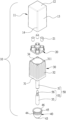
- FIG. 1 is an exploded view of a magnetic cap assembly according to the preferred embodiment of the present invention
- FIG. 2 is a top view of the magnetic cap assembly shown in FIG. 1 ;
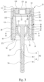
- FIG. 3 is a cross-sectional view of the magnetic cap assembly taken along a line A-A shown in FIG. 2 ;
- FIG. 4 is a cross-sectional view of an external cap of the magnetic cap assembly shown in FIG. 1 ;
- FIG. 5 is a cut-away view of a magnetic module of the magnetic cap assembly shown in FIG. 1 ;
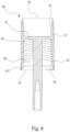
- FIG. 6 is a cross-sectional view of an internal cap of the magnetic cap assembly shown in FIG. 1 ;
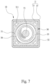
- FIG. 7 is a cross-sectional view of the magnetic cap assembly taken along a line B-B shown in FIG. 3 ;
- FIG. 8 is a cross-sectional view of a scrapper of the magnetic cap assembly shown in FIG. 1 ;
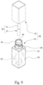
- FIG. 9 is an exploded view of a container for nail polish that includes a bottle and the magnetic cap assembly shown in FIG. 1 ;
- FIG. 10 is a perspective view of two containers as shown in FIG. 9 attracted to each other head to head;
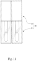
- FIG. 11 is a perspective view of two containers as shown in FIG. 9 attracted to each other side by side;
- FIG. 12 is a top view of a magnetic module of a magnetic cap assembly according to a second embodiment of the present invention.
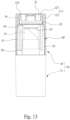
- FIG. 13 is a cross-sectional view of a magnetic cap assembly according to a third embodiment of the present invention.
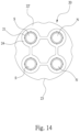
- FIG. 14 is a top view of a magnetic module of the magnetic cap assembly shown in FIG. 13 ;
- FIG. 15 is a perspective view of four containers equipped with magnetic cap assemblies as shown in FIG. 13 , attracted to one another side by side;
- FIG. 16 is a top view of a container including a magnetic cap assembly according to a fourth embodiment of the present invention.
- FIG. 17 is a cross-sectional view of the container taken along a line C-C shown in FIG. 16 ;
- FIG. 18 is a perspective view of five containers as shown in FIG. 16 , attracted to one another side by side.
- FIGS. 1 through 11 there is shown a magnetic cap assembly 10 according to a first embodiment of the present invention.
- the magnetic cap assembly 10 is used in a container for cosmetics so that the container attracts another container.
- the cosmetics can be mascara or lip gloss for example.
- the container can include a jar or bottle for instance.
- the magnetic cap assembly 10 includes an external cap 11 , a magnetic module (not numbered) and an internal cap 30 .
- the magnetic module includes a holder 20 and four magnets 21 for example.
- the internal cap 30 and the magnetic module are inserted in the external cap 11 .
- the magnetic module is located between the external cap 11 and the internal cap 30 .
- the magnetic cap assembly 10 can attract an object made of a ferromagnetic material such as iron, nickel, cobalt and any alloy of iron, nickel and/or cobalt.
- the external cap 11 includes a ceiling 12 , four walls 13 extending from the ceiling 12 , four corners 14 each of which extends between two adjacent ones of the walls 13 , and an open end 15 opposite to the ceiling 12 .
- the ceiling 12 is square portion.
- Each of the walls 13 is a rectangular portion.
- the corners 14 are preferably chamfered.
- At least the ceiling 12 and each of the walls 13 is coated with a protective film 17 .
- the protective films 17 are provided with a color corresponding to the cosmetics.
- the ceiling 12 includes a planar upper face. On a lower face, the ceiling 12 includes a boss 121 and four relatively thin portions 122 .
- the boss 121 extends from a center of the lower face of the ceiling 12 .
- the relatively thin portions 122 are located around the boss 121 .
- Each of the relatively thin portions 122 is located between a corresponding one of the corners 14 and the boss 121 .
- Each of the walls 13 includes a planar external face.
- An internal face of each of the walls 13 includes three sections so that the interior of the external cap 11 includes a lower space 131 in the vicinity of the ceiling 12 , an upper space 133 in the vicinity of the open end 15 , and a conical space 132 between the lower space 131 and the upper space 133 .
- the conical space 132 includes a large open end 134 next to the lower space 131 and a small open end 135 next to the upper space 133 .
- the external cap 11 further includes four tracks 16 located in the upper space 133 .
- Each of the tracks 16 extends along a boundary between the internal faces of two adjacent ones of the walls 13 .
- the tracks 16 , the ceiling 12 and the walls 13 are made in one piece.
- the magnetic module includes a holder 20 for holding four magnets 21 in position.
- the holder 20 includes a tray 22 , four sockets 24 and four walls 26 .
- the tray 22 , the sockets 24 and the walls 26 are made in one piece.
- the tray 22 is a square flat element.
- the tray 22 includes four cutouts 23 at four corners.
- the sockets 24 extend from an upper face of the tray 22 .
- Each of the socket 24 includes two external ribs 25 , a cave 27 and four internal ribs 28 .
- the external ribs 25 are used to enhance the strength of the sockets 24 .
- the cave 27 of each of the sockets 24 receives a corresponding one of the magnets 21 .
- the internal ribs 28 extend on the walls of the caves 27 of the sockets 24 .
- Each of the internal ribs 28 includes a sharp edge. The sharp edges of the internal ribs 28 contact the magnets 21 and hence keep them in position.
- the walls 26 extend from an upper face of the tray 22 . Each of the four walls 26 interconnects two adjacent ones of the sockets 24 .
- Each of the magnets 21 includes two magnetic poles, i.e., pole S and pole N.
- the poles N of two of the magnets 21 at a diagonal line of the tray 22 are located out of the corresponding caves 27 , and the poles S of these magnets 21 are inserted in the corresponding caves 27 .
- the poles S of the remaining ones of the magnets 21 are located out of the corresponding caves 27 , and the poles N of these two magnets 21 are inserted in the corresponding caves 27 .
- the magnetic module is inserted in the external cap 11 .
- the magnetic module which includes the holder 20 and the magnets 21 , is moved toward the ceiling 12 .
- the magnetic module is sequentially moved into the lower space 131 , the conical space 132 and the upper space 133 .
- the tracks 16 are inserted in the cutouts 23 so that the tray 22 is smoothly moved into the upper space 133 .
- Each of the magnets 21 includes a magnetic pole inserted in a corresponding one of the sockets 24 and another magnetic pole in contact with a corresponding one of the relatively thin portions 122 .
- Each of four edges (not numbered) of the tray 22 is in contact with a corresponding one of the walls 13 so that the holder 20 is not rotatable in the external cap 11 .
- the boss 121 is not in contact with the magnets 21 or the sockets 24 , and hence does not interfere with the insertion of the magnetic module into the external cap 11 .
- the internal cap 30 includes four walls 31 connected to one another and a partition 33 connected to the walls 31 .
- the partition 33 enhances the strength of the internal cap 30 .
- Each of the walls 31 is a rectangular portion that includes ribs 32 evenly formed on an internal face. The ribs 32 enhance the strength of the walls 31 .
- the walls 31 render the internal cap 30 a tubular element that includes an upper open end 36 , a lower open end 37 , a mass-reducing space 34 next to the upper open end 36 and an engaging space 35 next to the lower open end 37 .
- the mass-reducing space 34 is separated from the engaging space 35 by the partition 33 .
- the mass-reducing space 34 is used to reduce the mass of the internal cap 30 .
- the engaging space 35 is a stepped space that includes two sections divided by a shoulder 371 .
- the internal cap 30 further includes four recesses 311 , a thread 38 and elastic buckles 39 .
- the recesses 311 are located around the mass-reducing space 34 .
- the recesses 311 reduce the mass of the internal cap 30 like the mass-reducing space 34 .
- the thread 38 extends on an internal face of a section of the internal cap 30 in the engaging space 35 , between the partition 33 and the shoulder 371 .
- the elastic buckles 39 are separated from one another by a gap. Each of the elastic buckle 39 extends from an internal face of a corresponding one of the walls 31 , in the vicinity of the shoulder 371 .
- the internal cap 30 is inserted in the lower space 131 and the conical space 132 of the external cap 11 .
- the upper end of the internal cap 30 is sequentially moved through the open end 15 of the external cap 11 , the lower space 131 and the conical space 132 .
- the tracks 16 are abutted against the upper open end 36 of the internal cap 30 to prevent the internal cap 30 from moving further into the external cap 11 .
- the open end 15 is almost completely covered by the internal cap 30
- the lower open end 37 is the only passageway through which an object can be inserted in the engaging space 35 of the magnetic cap assembly 10 .
- the ribs 32 of the internal cap 30 contact the walls 13 of external cap 11 .
- the walls 13 of the external cap 11 squeeze the ribs 32 of the internal cap 30 while the ribs 32 of the internal cap 30 push the walls 13 of the external cap 11 .
- the ribs 32 are deformed to a limited extent. Friction between the ribs 32 and the walls 13 keep the internal cap 30 in the external cap 11 . That is, the internal cap 30 is fitted in the external cap 11 .
- the holder 20 is kept in the upper space 133 of the external cap 11 by the internal cap 30 .
- the magnets 21 are kept between the ceiling 12 of the external cap 11 and upper open end 36 of the internal cap 30 .
- the magnetic cap assembly 10 further includes a lash curler 50 according to the first embodiment of the present invention.
- the lash curler 50 includes a shank 51 and a bit 53 .
- the shank 51 includes an upper end made in one piece with a lower face of the partition 33 .
- the shank 51 extends along an axis of the engaging space 35 (or the thread 38 ) from the partition 33 .
- a lower end located out of the shank 51 extends beyond the lower open end 37 of the internal cap 30 of the magnetic cap assembly 10 because the length of the shank 51 is larger than the depth of the engaging space 35 .
- the shank 51 includes a bore 52 in the lower end.
- the bit 53 includes a rod 54 and a piece of sponge 55 .
- the rod 54 includes a mushroom-shaped portion 56 at an upper end.
- the mushroom-shaped portion 56 is made with a diameter marginally larger than a diameter of the bore 52 .
- the mushroom-shaped portion 56 is fitted in the bore 52 , thereby firmly connecting the bit 53 to the shank 51 .
- the piece of sponge 55 is in the form of a tube.
- a lower section of the rod 54 is fitted in the piece of sponge 55 .
- the magnetic cap assembly 10 further includes a scrapper 40 according to the first embodiment of the present invention.
- the scrapper 40 further includes a bowl 44 , a ferrule 43 extending from a lower end of the bowl 44 , a gasket 46 extending from an upper end of the bowl 44 , and a flange 45 extending from an external face of the bowl 44 in the vicinity of the gasket 46 .
- the ferrule 43 extends around a small open end 42 of the scrapper 40 .
- the gasket 46 extends around a large open end 41 of the scrapper 40 .
- the scrapper 40 is inserted in the engaging space 35 of the internal cap 30 .
- the bowl 44 of the scrapper 40 is located around the shank 51 of the lash curler 50 .
- the large open end 41 is located in the vicinity of the partition 33 .
- the gasket 46 is abutted against the partition 33 .
- the ferrule 43 tightly holds on to the shank 51 , thereby keeping the scrapper 40 on the shank 51 .
- the scrapper 40 is used to prevent leakage.
- a container 60 includes a bottle 61 in addition to the magnetic cap assembly 10 .
- the bottle 61 includes a hollow body 62 and a bottle neck 63 extending from an upper end of the hollow body 62 .
- the hollow body 62 includes a chamber 65 for containing mascara, lip gloss or any other proper type of cosmetics.
- the hollow body 62 is preferably transparent so that the mascara in the chamber 65 is visible through the hollow body 62 .
- the bottle neck 63 includes a bottle mouth 64 via which the mascara is filled in or poured from the chamber 65 .
- the bottle 61 further includes a thread 66 extending on an external face of the bottle neck 63 and locking portions 67 formed below the thread 66 .
- the lash curler 50 is inserted in the chamber 65 of the hollow body 62 via the bottle mouth 64 .
- the bottle neck 63 can be inserted in and covered by the magnetic cap assembly 10 by engaging the thread 38 with the thread 66 .
- the thread 38 is kept engaged with the thread 66 by engaging the elastic buckles 39 with the locking portions 67 , even in cases of vibration.
- the bottle 61 is firmly closed by the magnetic cap assembly 10 .
- the bit 53 is taken from the bottle 61 through the bottle mouth 64 , which is made in the bottle neck 63 .
- the sponge 55 may leave some of the mascara in the bottle mouth 64 .
- two containers 60 are attracted to each other, head to head. That is, the magnetic cap assemblies 10 are attracted to each other, head to head.
- two containers 60 are attracted to each other, side by side. That is, the magnetic cap assemblies 10 are attracted to each other, side by side.
- the containers 60 are arranged in good order when they are located in a backpack, a purse, a handbag or the like.
- the containers 60 leave more space in the backpack, the purse or the handbag in such good order than otherwise.
- FIG. 12 there is shown a magnetic cap assembly according to a second embodiment of the present invention.
- the second embodiment is identical to the first embodiment except for the arrangement of the magnets 21 in the holder 20 .
- the poles S of two of the magnets 21 arranged along a side of the holder 20 are located out of the corresponding sockets 24 and the poles N of the remaining ones of the magnets 21 are located out of the corresponding sockets 24 .
- FIGS. 13 and 14 there is shown a magnetic cap assembly 10 according to a third embodiment of the present invention.
- the third embodiment is identical to the second embodiment except for several features.
- an external cap 11 ′ is used instead of the external cap 11 .
- the external cap 11 ′ includes a circular ceiling 12 ′ and a cylindrical wall 13 ′ instead of the square ceiling 12 and the walls 13 .
- the external cap 11 ′ includes a circular upper space 133 ′ instead of the square upper space 133
- the holder 20 includes a circular tray 22 ′ inserted in the circular upper space 133 ′.
- an internal cap 30 ′ that includes a cylindrical wall 13 ′ instead of the walls 13 of the internal cap 30 .
- the internal cap 30 ′ includes a partition 33 ′ instead of the partition 33 .
- the partition 33 ′ is located higher in the internal cap 30 ′ than the partition 33 in the internal cap.
- the internal cap 30 ′ includes a mass-reducing space 34 ′ shallower than the mass-reducing space 34 and an engaging space 35 ′ deeper than the engaging space 35 .
- the internal cap 30 ′ does not include any thread, shoulder, elastic buckles, lash curler or scrapper.
- the magnetic cap assembly 10 is used in a container 70 .
- the container 70 further includes a grip 71 for holding cosmetics 72 such as lip gloss.
- a magnetic cap assembly 10 according to a fourth embodiment of the present invention is shown.
- the fourth embodiment is identical to the first embodiment except for several features.
- an external cap 11 ′′ is used instead of the external cap 11 .
- the external cap 11 ′′ includes a teardrop-shaped ceiling 12 ′′ and a wall 13 ′′ instead of the square ceiling 12 and the walls 13 .
- the external cap 11 ′′ includes a teardrop-shaped upper space 133 ′′.
- the ceiling 12 ′′ does not include any boss, relatively thin portions or ribs.
- the wall 13 ′′ does not include any lower space or conical space.
- an internal cap 30 ′′ is included instead of the internal cap 30 .
- the internal cap 30 ′′ is teardrop-shaped.
- the internal cap 30 ′′ includes a wall 31 ′′ and a partition 33 ′′.
- the partition 33 ′′ is in a different position in the wall 31 ′′ than the partition 33 in the wall 31 .
- the depth of the engaging space 35 ′′ is different from the depth of the engaging space 35 .
- the internal cap 30 ′′ does not include any mass-reducing space or thread.
- the partition 33 ′′ includes four bores 75 .
- Each of the bores 75 receives a magnetic module, which includes a holder 20 and four magnets 21 .
- the magnetic modules are inserted in the upper space 133 ′′ of the external cap 11 ′′ by the internal cap 30 ′′.
- each of the containers 70 ′ includes a box 73 and a magnetic cap assembly 10 .
- the wall 31 ′′ includes a lug 74 pivotally connected to a box 73 by a pin (not numbered).
- the box 73 and the magnetic cap assembly 10 form a container 70 ′.
- the box 73 can be used to contain cosmetics in the form of powder.
Landscapes
- Engineering & Computer Science (AREA)
- Mechanical Engineering (AREA)
- Closures For Containers (AREA)
Abstract
Description
Claims (3)
Priority Applications (1)
| Application Number | Priority Date | Filing Date | Title |
|---|---|---|---|
| US16/684,571 US11751663B2 (en) | 2019-11-14 | 2019-11-14 | Magnetic cap assembly and a container using the same |
Applications Claiming Priority (1)
| Application Number | Priority Date | Filing Date | Title |
|---|---|---|---|
| US16/684,571 US11751663B2 (en) | 2019-11-14 | 2019-11-14 | Magnetic cap assembly and a container using the same |
Publications (2)
| Publication Number | Publication Date |
|---|---|
| US20210145149A1 US20210145149A1 (en) | 2021-05-20 |
| US11751663B2 true US11751663B2 (en) | 2023-09-12 |
Family
ID=75908386
Family Applications (1)
| Application Number | Title | Priority Date | Filing Date |
|---|---|---|---|
| US16/684,571 Active 2041-12-09 US11751663B2 (en) | 2019-11-14 | 2019-11-14 | Magnetic cap assembly and a container using the same |
Country Status (1)
| Country | Link |
|---|---|
| US (1) | US11751663B2 (en) |
Citations (15)
| Publication number | Priority date | Publication date | Assignee | Title |
|---|---|---|---|---|
| FR2800040A1 (en) * | 1999-10-25 | 2001-04-27 | Pivaudran Dev G | PACKAGING DEVICE PROVIDED WITH A RELATIVE POSITIONING SYSTEM |
| US20080066774A1 (en) * | 2006-03-17 | 2008-03-20 | L'oreal | Packaging and applicator device |
| US20120294666A1 (en) * | 2011-05-17 | 2012-11-22 | Anisa International, Inc. | Multi-applicator tool |
| US9592935B1 (en) * | 2015-09-25 | 2017-03-14 | Elc Management, Llc | Screw-type container-closure systems with magnetic feature |
| US20170088305A1 (en) * | 2015-09-25 | 2017-03-30 | Elc Management Llc | Screw-Type Closure Systems With Magnetic Feature |
| US20170127802A1 (en) * | 2015-11-10 | 2017-05-11 | Wensheng Chen | Sealed packaging for cosmetics |
| US20170265618A1 (en) * | 2016-03-16 | 2017-09-21 | HCT Group Holdings Limited | Cosmetic container with closure |
| CN108041792A (en) * | 2018-02-09 | 2018-05-18 | 阿蓓亚塑料实业(上海)有限公司 | Lipstick tube |
| US20190239618A1 (en) * | 2018-02-08 | 2019-08-08 | Cosmopak U.S.A. LLC | Cosmetic container with magnetic closure |
| WO2019153167A1 (en) * | 2018-02-08 | 2019-08-15 | 陈文胜 | Cosmetics container |
| US20200146422A1 (en) * | 2017-06-02 | 2020-05-14 | Ejaz Kamboj | Cosmetic holder system |
| US20200383457A1 (en) * | 2019-06-04 | 2020-12-10 | L'oreal | Applicator cap with interconnect feature |
| US20210321747A1 (en) * | 2018-09-16 | 2021-10-21 | Yves Swiss Ag | Container for cosmetics and other products with a limited period of use, or for the time-controlled presentation of products, with integrated clock, electronics system and timer function |
| US11230464B2 (en) * | 2019-10-17 | 2022-01-25 | Elc Management Llc | Cosmetic dosing system |
| US20230002123A1 (en) * | 2021-07-05 | 2023-01-05 | Libo Cosmetics Co., Ltd. | Container for cosmetics |
-
2019
- 2019-11-14 US US16/684,571 patent/US11751663B2/en active Active
Patent Citations (15)
| Publication number | Priority date | Publication date | Assignee | Title |
|---|---|---|---|---|
| FR2800040A1 (en) * | 1999-10-25 | 2001-04-27 | Pivaudran Dev G | PACKAGING DEVICE PROVIDED WITH A RELATIVE POSITIONING SYSTEM |
| US20080066774A1 (en) * | 2006-03-17 | 2008-03-20 | L'oreal | Packaging and applicator device |
| US20120294666A1 (en) * | 2011-05-17 | 2012-11-22 | Anisa International, Inc. | Multi-applicator tool |
| US9592935B1 (en) * | 2015-09-25 | 2017-03-14 | Elc Management, Llc | Screw-type container-closure systems with magnetic feature |
| US20170088305A1 (en) * | 2015-09-25 | 2017-03-30 | Elc Management Llc | Screw-Type Closure Systems With Magnetic Feature |
| US20170127802A1 (en) * | 2015-11-10 | 2017-05-11 | Wensheng Chen | Sealed packaging for cosmetics |
| US20170265618A1 (en) * | 2016-03-16 | 2017-09-21 | HCT Group Holdings Limited | Cosmetic container with closure |
| US20200146422A1 (en) * | 2017-06-02 | 2020-05-14 | Ejaz Kamboj | Cosmetic holder system |
| US20190239618A1 (en) * | 2018-02-08 | 2019-08-08 | Cosmopak U.S.A. LLC | Cosmetic container with magnetic closure |
| WO2019153167A1 (en) * | 2018-02-08 | 2019-08-15 | 陈文胜 | Cosmetics container |
| CN108041792A (en) * | 2018-02-09 | 2018-05-18 | 阿蓓亚塑料实业(上海)有限公司 | Lipstick tube |
| US20210321747A1 (en) * | 2018-09-16 | 2021-10-21 | Yves Swiss Ag | Container for cosmetics and other products with a limited period of use, or for the time-controlled presentation of products, with integrated clock, electronics system and timer function |
| US20200383457A1 (en) * | 2019-06-04 | 2020-12-10 | L'oreal | Applicator cap with interconnect feature |
| US11230464B2 (en) * | 2019-10-17 | 2022-01-25 | Elc Management Llc | Cosmetic dosing system |
| US20230002123A1 (en) * | 2021-07-05 | 2023-01-05 | Libo Cosmetics Co., Ltd. | Container for cosmetics |
Also Published As
| Publication number | Publication date |
|---|---|
| US20210145149A1 (en) | 2021-05-20 |
Similar Documents
| Publication | Publication Date | Title |
|---|---|---|
| KR101347659B1 (en) | Cosmetic container | |
| US8371313B2 (en) | Brushes with interchangeable heads | |
| US7913849B2 (en) | Lunch box with configurable handle, accessories, containers, and display inserts | |
| US8141562B2 (en) | Cosmetic container system including tab-hinged cover | |
| WO2019046297A1 (en) | Cosmetic container with removable palette | |
| US7028843B2 (en) | Cosmetics case | |
| BRPI0714561A2 (en) | compact cosmetic container | |
| US20080000493A1 (en) | Flipping compact assembly | |
| US20080173324A1 (en) | Compact Case with Detachable Leaves | |
| KR200479844Y1 (en) | Cosmetic container having opening and shutting structure using magnetic force | |
| US20180064229A1 (en) | Compacts and apparatuses for holding cosmetics | |
| US11751663B2 (en) | Magnetic cap assembly and a container using the same | |
| CN111083921A (en) | Portable cosmetic box | |
| JP2016016879A (en) | Wide-mouthed container with auxiliary tool | |
| US20190142134A1 (en) | Cosmetics case | |
| US20220265022A1 (en) | An electronic device case and a make-up applicator assembly for use with an electronic device case | |
| US10143291B2 (en) | Cosmetic case and dispenser assembly | |
| US10653257B2 (en) | Wine bottle and glass carrier | |
| US20210137246A1 (en) | Cosmetic stamp configuration and method for using the same | |
| KR101412429B1 (en) | Color tone cosmetic vessel for putting brush on | |
| US20150274381A1 (en) | Apparatus for storage of materials | |
| KR101091881B1 (en) | Powder cosmetic case | |
| US20200029675A1 (en) | Compact cosmetic case | |
| KR20200038771A (en) | Cosmetic case preventing from being contaminated mirror | |
| WO2019153167A1 (en) | Cosmetics container |
Legal Events
| Date | Code | Title | Description |
|---|---|---|---|
| AS | Assignment |
Owner name: LIBO COSMETICS CO., LTD., TAIWAN Free format text: ASSIGNMENT OF ASSIGNORS INTEREST;ASSIGNOR:LIN, HSIAO-YUN;REEL/FRAME:051021/0261 Effective date: 20191025 |
|
| FEPP | Fee payment procedure |
Free format text: ENTITY STATUS SET TO UNDISCOUNTED (ORIGINAL EVENT CODE: BIG.); ENTITY STATUS OF PATENT OWNER: SMALL ENTITY |
|
| FEPP | Fee payment procedure |
Free format text: ENTITY STATUS SET TO SMALL (ORIGINAL EVENT CODE: SMAL); ENTITY STATUS OF PATENT OWNER: SMALL ENTITY |
|
| STPP | Information on status: patent application and granting procedure in general |
Free format text: NON FINAL ACTION MAILED |
|
| STPP | Information on status: patent application and granting procedure in general |
Free format text: RESPONSE TO NON-FINAL OFFICE ACTION ENTERED AND FORWARDED TO EXAMINER |
|
| STPP | Information on status: patent application and granting procedure in general |
Free format text: NON FINAL ACTION MAILED |
|
| STPP | Information on status: patent application and granting procedure in general |
Free format text: FINAL REJECTION MAILED |
|
| STPP | Information on status: patent application and granting procedure in general |
Free format text: RESPONSE AFTER FINAL ACTION FORWARDED TO EXAMINER |
|
| STPP | Information on status: patent application and granting procedure in general |
Free format text: PUBLICATIONS -- ISSUE FEE PAYMENT VERIFIED |
|
| STCF | Information on status: patent grant |
Free format text: PATENTED CASE |