US11738907B2 - Stackable and ventable containers - Google Patents
Stackable and ventable containers Download PDFInfo
- Publication number
- US11738907B2 US11738907B2 US16/445,638 US201916445638A US11738907B2 US 11738907 B2 US11738907 B2 US 11738907B2 US 201916445638 A US201916445638 A US 201916445638A US 11738907 B2 US11738907 B2 US 11738907B2
- Authority
- US
- United States
- Prior art keywords
- container
- base
- lid
- vent
- containers
- Prior art date
- Legal status (The legal status is an assumption and is not a legal conclusion. Google has not performed a legal analysis and makes no representation as to the accuracy of the status listed.)
- Active, expires
Links
Images


Classifications
-
- B—PERFORMING OPERATIONS; TRANSPORTING
- B65—CONVEYING; PACKING; STORING; HANDLING THIN OR FILAMENTARY MATERIAL
- B65D—CONTAINERS FOR STORAGE OR TRANSPORT OF ARTICLES OR MATERIALS, e.g. BAGS, BARRELS, BOTTLES, BOXES, CANS, CARTONS, CRATES, DRUMS, JARS, TANKS, HOPPERS, FORWARDING CONTAINERS; ACCESSORIES, CLOSURES, OR FITTINGS THEREFOR; PACKAGING ELEMENTS; PACKAGES
- B65D21/00—Nestable, stackable or joinable containers; Containers of variable capacity
- B65D21/02—Containers specially shaped, or provided with fittings or attachments, to facilitate nesting, stacking, or joining together
- B65D21/0209—Containers specially shaped, or provided with fittings or attachments, to facilitate nesting, stacking, or joining together stackable or joined together one-upon-the-other in the upright or upside-down position
- B65D21/0217—Containers with a closure presenting stacking elements
- B65D21/0222—Containers with a closure presenting stacking elements the closure and the bottom presenting co-operating peripheral ribs and grooves
-
- B—PERFORMING OPERATIONS; TRANSPORTING
- B65—CONVEYING; PACKING; STORING; HANDLING THIN OR FILAMENTARY MATERIAL
- B65D—CONTAINERS FOR STORAGE OR TRANSPORT OF ARTICLES OR MATERIALS, e.g. BAGS, BARRELS, BOTTLES, BOXES, CANS, CARTONS, CRATES, DRUMS, JARS, TANKS, HOPPERS, FORWARDING CONTAINERS; ACCESSORIES, CLOSURES, OR FITTINGS THEREFOR; PACKAGING ELEMENTS; PACKAGES
- B65D21/00—Nestable, stackable or joinable containers; Containers of variable capacity
- B65D21/02—Containers specially shaped, or provided with fittings or attachments, to facilitate nesting, stacking, or joining together
- B65D21/04—Open-ended containers shaped to be nested when empty and to be superposed when full
- B65D21/048—Identical stackable containers specially adapted for retaining the same orientation when nested, e.g. the upper container being fixed or slightly rotatable during the nesting operation
-
- B—PERFORMING OPERATIONS; TRANSPORTING
- B65—CONVEYING; PACKING; STORING; HANDLING THIN OR FILAMENTARY MATERIAL
- B65D—CONTAINERS FOR STORAGE OR TRANSPORT OF ARTICLES OR MATERIALS, e.g. BAGS, BARRELS, BOTTLES, BOXES, CANS, CARTONS, CRATES, DRUMS, JARS, TANKS, HOPPERS, FORWARDING CONTAINERS; ACCESSORIES, CLOSURES, OR FITTINGS THEREFOR; PACKAGING ELEMENTS; PACKAGES
- B65D43/00—Lids or covers for rigid or semi-rigid containers
- B65D43/14—Non-removable lids or covers
- B65D43/16—Non-removable lids or covers hinged for upward or downward movement
- B65D43/162—Non-removable lids or covers hinged for upward or downward movement the container, the lid and the hinge being made of one piece
-
- B—PERFORMING OPERATIONS; TRANSPORTING
- B65—CONVEYING; PACKING; STORING; HANDLING THIN OR FILAMENTARY MATERIAL
- B65D—CONTAINERS FOR STORAGE OR TRANSPORT OF ARTICLES OR MATERIALS, e.g. BAGS, BARRELS, BOTTLES, BOXES, CANS, CARTONS, CRATES, DRUMS, JARS, TANKS, HOPPERS, FORWARDING CONTAINERS; ACCESSORIES, CLOSURES, OR FITTINGS THEREFOR; PACKAGING ELEMENTS; PACKAGES
- B65D51/00—Closures not otherwise provided for
- B65D51/16—Closures not otherwise provided for with means for venting air or gas
- B65D51/1672—Closures not otherwise provided for with means for venting air or gas whereby venting occurs by manual actuation of the closure or other element
- B65D51/1677—Closures not otherwise provided for with means for venting air or gas whereby venting occurs by manual actuation of the closure or other element by rupturing a portion of the closure
-
- B—PERFORMING OPERATIONS; TRANSPORTING
- B65—CONVEYING; PACKING; STORING; HANDLING THIN OR FILAMENTARY MATERIAL
- B65D—CONTAINERS FOR STORAGE OR TRANSPORT OF ARTICLES OR MATERIALS, e.g. BAGS, BARRELS, BOTTLES, BOXES, CANS, CARTONS, CRATES, DRUMS, JARS, TANKS, HOPPERS, FORWARDING CONTAINERS; ACCESSORIES, CLOSURES, OR FITTINGS THEREFOR; PACKAGING ELEMENTS; PACKAGES
- B65D21/00—Nestable, stackable or joinable containers; Containers of variable capacity
- B65D21/02—Containers specially shaped, or provided with fittings or attachments, to facilitate nesting, stacking, or joining together
- B65D21/0233—Nestable containers
-
- B—PERFORMING OPERATIONS; TRANSPORTING
- B65—CONVEYING; PACKING; STORING; HANDLING THIN OR FILAMENTARY MATERIAL
- B65D—CONTAINERS FOR STORAGE OR TRANSPORT OF ARTICLES OR MATERIALS, e.g. BAGS, BARRELS, BOTTLES, BOXES, CANS, CARTONS, CRATES, DRUMS, JARS, TANKS, HOPPERS, FORWARDING CONTAINERS; ACCESSORIES, CLOSURES, OR FITTINGS THEREFOR; PACKAGING ELEMENTS; PACKAGES
- B65D2205/00—Venting means
-
- B—PERFORMING OPERATIONS; TRANSPORTING
- B65—CONVEYING; PACKING; STORING; HANDLING THIN OR FILAMENTARY MATERIAL
- B65D—CONTAINERS FOR STORAGE OR TRANSPORT OF ARTICLES OR MATERIALS, e.g. BAGS, BARRELS, BOTTLES, BOXES, CANS, CARTONS, CRATES, DRUMS, JARS, TANKS, HOPPERS, FORWARDING CONTAINERS; ACCESSORIES, CLOSURES, OR FITTINGS THEREFOR; PACKAGING ELEMENTS; PACKAGES
- B65D2543/00—Lids or covers essentially for box-like containers
- B65D2543/00009—Details of lids or covers for rigid or semi-rigid containers
- B65D2543/00018—Overall construction of the lid
- B65D2543/00064—Shape of the outer periphery
- B65D2543/00074—Shape of the outer periphery curved
- B65D2543/00101—Shape of the outer periphery curved square-like or rectangular-like
-
- B—PERFORMING OPERATIONS; TRANSPORTING
- B65—CONVEYING; PACKING; STORING; HANDLING THIN OR FILAMENTARY MATERIAL
- B65D—CONTAINERS FOR STORAGE OR TRANSPORT OF ARTICLES OR MATERIALS, e.g. BAGS, BARRELS, BOTTLES, BOXES, CANS, CARTONS, CRATES, DRUMS, JARS, TANKS, HOPPERS, FORWARDING CONTAINERS; ACCESSORIES, CLOSURES, OR FITTINGS THEREFOR; PACKAGING ELEMENTS; PACKAGES
- B65D2543/00—Lids or covers essentially for box-like containers
- B65D2543/00009—Details of lids or covers for rigid or semi-rigid containers
- B65D2543/00018—Overall construction of the lid
- B65D2543/00222—Hollow and made of one piece
-
- B—PERFORMING OPERATIONS; TRANSPORTING
- B65—CONVEYING; PACKING; STORING; HANDLING THIN OR FILAMENTARY MATERIAL
- B65D—CONTAINERS FOR STORAGE OR TRANSPORT OF ARTICLES OR MATERIALS, e.g. BAGS, BARRELS, BOTTLES, BOXES, CANS, CARTONS, CRATES, DRUMS, JARS, TANKS, HOPPERS, FORWARDING CONTAINERS; ACCESSORIES, CLOSURES, OR FITTINGS THEREFOR; PACKAGING ELEMENTS; PACKAGES
- B65D2543/00—Lids or covers essentially for box-like containers
- B65D2543/00009—Details of lids or covers for rigid or semi-rigid containers
- B65D2543/00018—Overall construction of the lid
- B65D2543/00259—Materials used
- B65D2543/00296—Plastic
-
- B—PERFORMING OPERATIONS; TRANSPORTING
- B65—CONVEYING; PACKING; STORING; HANDLING THIN OR FILAMENTARY MATERIAL
- B65D—CONTAINERS FOR STORAGE OR TRANSPORT OF ARTICLES OR MATERIALS, e.g. BAGS, BARRELS, BOTTLES, BOXES, CANS, CARTONS, CRATES, DRUMS, JARS, TANKS, HOPPERS, FORWARDING CONTAINERS; ACCESSORIES, CLOSURES, OR FITTINGS THEREFOR; PACKAGING ELEMENTS; PACKAGES
- B65D2543/00—Lids or covers essentially for box-like containers
- B65D2543/00009—Details of lids or covers for rigid or semi-rigid containers
- B65D2543/00342—Central part of the lid
- B65D2543/00351—Dome-like
-
- B—PERFORMING OPERATIONS; TRANSPORTING
- B65—CONVEYING; PACKING; STORING; HANDLING THIN OR FILAMENTARY MATERIAL
- B65D—CONTAINERS FOR STORAGE OR TRANSPORT OF ARTICLES OR MATERIALS, e.g. BAGS, BARRELS, BOTTLES, BOXES, CANS, CARTONS, CRATES, DRUMS, JARS, TANKS, HOPPERS, FORWARDING CONTAINERS; ACCESSORIES, CLOSURES, OR FITTINGS THEREFOR; PACKAGING ELEMENTS; PACKAGES
- B65D2543/00—Lids or covers essentially for box-like containers
- B65D2543/00009—Details of lids or covers for rigid or semi-rigid containers
- B65D2543/00444—Contact between the container and the lid
- B65D2543/00592—Snapping means
- B65D2543/00601—Snapping means on the container
- B65D2543/00611—Profiles
- B65D2543/00657—U-shaped or inverted U
-
- B—PERFORMING OPERATIONS; TRANSPORTING
- B65—CONVEYING; PACKING; STORING; HANDLING THIN OR FILAMENTARY MATERIAL
- B65D—CONTAINERS FOR STORAGE OR TRANSPORT OF ARTICLES OR MATERIALS, e.g. BAGS, BARRELS, BOTTLES, BOXES, CANS, CARTONS, CRATES, DRUMS, JARS, TANKS, HOPPERS, FORWARDING CONTAINERS; ACCESSORIES, CLOSURES, OR FITTINGS THEREFOR; PACKAGING ELEMENTS; PACKAGES
- B65D2543/00—Lids or covers essentially for box-like containers
- B65D2543/00009—Details of lids or covers for rigid or semi-rigid containers
- B65D2543/00444—Contact between the container and the lid
- B65D2543/00592—Snapping means
- B65D2543/00601—Snapping means on the container
- B65D2543/00675—Periphery concerned
- B65D2543/00694—Segments
-
- B—PERFORMING OPERATIONS; TRANSPORTING
- B65—CONVEYING; PACKING; STORING; HANDLING THIN OR FILAMENTARY MATERIAL
- B65D—CONTAINERS FOR STORAGE OR TRANSPORT OF ARTICLES OR MATERIALS, e.g. BAGS, BARRELS, BOTTLES, BOXES, CANS, CARTONS, CRATES, DRUMS, JARS, TANKS, HOPPERS, FORWARDING CONTAINERS; ACCESSORIES, CLOSURES, OR FITTINGS THEREFOR; PACKAGING ELEMENTS; PACKAGES
- B65D2543/00—Lids or covers essentially for box-like containers
- B65D2543/00009—Details of lids or covers for rigid or semi-rigid containers
- B65D2543/00444—Contact between the container and the lid
- B65D2543/00592—Snapping means
- B65D2543/00712—Snapping means on the lid
- B65D2543/00722—Profiles
- B65D2543/00768—U-shaped or inverted U
-
- B—PERFORMING OPERATIONS; TRANSPORTING
- B65—CONVEYING; PACKING; STORING; HANDLING THIN OR FILAMENTARY MATERIAL
- B65D—CONTAINERS FOR STORAGE OR TRANSPORT OF ARTICLES OR MATERIALS, e.g. BAGS, BARRELS, BOTTLES, BOXES, CANS, CARTONS, CRATES, DRUMS, JARS, TANKS, HOPPERS, FORWARDING CONTAINERS; ACCESSORIES, CLOSURES, OR FITTINGS THEREFOR; PACKAGING ELEMENTS; PACKAGES
- B65D2543/00—Lids or covers essentially for box-like containers
- B65D2543/00009—Details of lids or covers for rigid or semi-rigid containers
- B65D2543/00444—Contact between the container and the lid
- B65D2543/00592—Snapping means
- B65D2543/00712—Snapping means on the lid
- B65D2543/00787—Periphery concerned
- B65D2543/00805—Segments
-
- B—PERFORMING OPERATIONS; TRANSPORTING
- B65—CONVEYING; PACKING; STORING; HANDLING THIN OR FILAMENTARY MATERIAL
- B65D—CONTAINERS FOR STORAGE OR TRANSPORT OF ARTICLES OR MATERIALS, e.g. BAGS, BARRELS, BOTTLES, BOXES, CANS, CARTONS, CRATES, DRUMS, JARS, TANKS, HOPPERS, FORWARDING CONTAINERS; ACCESSORIES, CLOSURES, OR FITTINGS THEREFOR; PACKAGING ELEMENTS; PACKAGES
- B65D2543/00—Lids or covers essentially for box-like containers
- B65D2543/00009—Details of lids or covers for rigid or semi-rigid containers
- B65D2543/00824—Means for facilitating removing of the closure
- B65D2543/00833—Integral tabs, tongues, handles or similar
- B65D2543/00842—Integral tabs, tongues, handles or similar outside of the lid
Definitions
- the present disclosure generally relates to stackable containers having vents and to containers that are easily separated when nested together.
- FIG. 1 A is a perspective view of an embodiment of a stackable container in an open position with its vent in a closed configuration.
- FIG. 1 B is a perspective view of the container of FIG. 1 A after the lid has been moved to the base as shown in FIG. 1 A such that the container is in a closed position.
- FIG. 1 C is a perspective view of the container of FIG. 1 B turned upside down to show the configuration of the bottom end of the base when the container is in the closed position.
- FIG. 1 D is an enlarged perspective view of the section encircled at 1 D of the container of FIG. 1 B .
- FIG. 1 E is a cross-sectional view of the lid and the base of the containers of FIG. 1 D taken along cutting line 1 E- 1 E of FIG. 1 D to show the locking cover of the lid over the locking tab of the base.
- FIG. 1 F is a cross-sectional view of the lid and the base of the containers of FIG. 1 E to show the locking cover of the lid moving relative to the locking tab of the base.
- FIG. 1 G is a cross-sectional view of the lid and the base of the containers of FIG. 1 F showing the locking cover of the lid separated from the locking tab of the base.
- FIG. 2 A is a side view of a first container in the closed position stacked on a second container in the closed position that are in a stacked arrangement to show the vertical offset of the stacking structures relative to the adjacent platforms.
- FIG. 2 B is a perspective view of a first container in the closed position stacked on a second container in the closed position with a cut-away to show two of the vents of the first container and the corresponding vent portals of the second container.
- FIG. 2 C is an enlarged perspective view of the section encircled at 2 C of the containers of FIG. 2 B showing a vent in a closed configuration.
- FIG. 2 D is an enlarged perspective view corresponding to the enlarged perspective view of FIG. 2 C but showing the C-shaped vent in the open configuration with the flap separated from the surrounding lid platform.
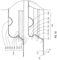
- FIG. 3 A is a perspective view of three containers as shown in FIG. 1 A in an open position, showing the containers positioned to be nested together.
- FIG. 3 B is an enlarged perspective view of the section encircled at 3 A of the containers of FIG. 3 A .
- FIG. 3 C shows the containers after being compressed towards each other in the nested arrangement.
- FIG. 3 D is a cross-sectional view of the locking tabs of three bases of the three stacked containers of FIG. 3 A after the bases have been compressed towards each other in the nested arrangement but not far enough for a bump in a flat top of a head of a locking tab to contact an adjacent flat top
- FIG. 3 E is a cross-sectional view of the locking tabs of three bases of the three stacked containers of FIG. 3 C after the bases have been further compressed towards each other relative to the cross-section view in FIG. 3 D such that a bump in a flat top of a head of a locking tab contacts an adjacent flat top.
- inventive concepts will now be described more fully hereinafter with reference to the accompanying drawings, in which exemplary embodiments of the inventive concepts are shown.
- inventive concepts are not limited to the following exemplary embodiments, and may be implemented in various forms. Accordingly, the exemplary embodiments are provided only to disclose the inventive concepts and let those skilled in the art know the category of the inventive concepts.
- embodiments of the inventive concepts are not limited to the specific examples provided herein.
- the same reference numerals or the same reference designators denote the same elements throughout the specification.
- exemplary embodiments are described herein with reference to cross-sectional views, perspective views, and/or top or plan views that are idealized exemplary views. Accordingly, variations from the shapes of the illustrations as a result, for example, of manufacturing techniques and/or tolerances, are to be expected. Thus, exemplary embodiments should not be construed as limited to the shapes of regions illustrated herein but are to include deviations in shapes that result, for example, from manufacturing. For example, an edge may be illustrated with sharp ends and without rounded or curved features even though such rounded or curved features may be preferable. Thus, the regions or elements illustrated in the figures may be schematic in nature and their shapes may not illustrate the actual shape of a region or an element of a container and are not intended to limit the scope of example embodiments.
- inventions disclosed herein relate to containers that may be used, for example, in the food industry.
- embodiments disclosed herein relate to containers that may be stored in a nested arrangement, may be used for containing and/or transporting food products in a stacked arrangement, and may vent heat and/or moisture while in a stacked arrangement.
- Food containers are used by consumers for packaging take-out items and/or leftovers.
- Such containers may contain hot food, which may warm the air within the container. The warm air in turn may cause moisture to condense onto the cooler sides and/or top of the container, which can drip onto the food. While condensation may not affect the quality of all hot food, items such as fried goods can become soggy upon exposure to such moisture. For example, if the hot food includes french fries and a hamburger with a bun, any condensation that forms can dampen the bun, rendering it unappetizing and/or unable to be held to physically support the hamburger for convenient consumption.
- the venting of the food containers to release the warm air from the interior of the container avoids undesirable condensation from affecting the food product.
- the vents prevent condensation that forms from hot food contents from adversely affect the quality of the food products contained therein.
- the container is stackable, including when closed and loaded with hot food, but still allow heat and/or moisture to vent from each of the containers when multiple containers are stacked together.
- Restaurants and other users of food packaging use containers to package a variety of food products having a variety of temperatures.
- the containers are used to package food products, and are ideally compact when open and nested, and when closed and stacked.
- the containers are easily separated when nested in the open position and then loaded with food.
- Such containers are also easy to load with food and are efficiently designed, such as being readily foldable.
- the containers are economically and/or environmentally appealing, and able to maintain the quality and temperature of the food product stored inside.
- the design of the disclosed containers permits the containers to be efficiently nested together when open, and multiple closed containers may be stacked together while maintaining their venting capacity. When stacked, the containers enable the stack to stay together without tipping. However, the stacked containers are easily separated from each other when desired such that the food loaded in the containers may be consumed.
- vented containers as disclosed herein can advantageously be supplied to a user in an open, loosely nested arrangement as shown, for example, in FIG. 3 A , or in an open, tightly nested stack as shown in FIG. 3 C .
- the user can load food into the container and can then close the container completely by folding the lid onto the base as shown in FIG. 1 B .
- embodiments are disclosed that enable the lid to couple with the base of the container as shown in FIGS. 2 A- 2 B .
- Some embodiments of the container may include a vent or multiple vents configured to release heat and/or moisture vapor that may form when a hot item is placed into the container.
- An end user e.g., the consumer
- Embodiments of the vented containers are stackable in a closed position. Further details of embodiments of the disclosed containers are provided below.
- FIGS. 1 A- 1 G depict a container 100 .
- FIGS. 2 A- 2 D depict closed containers in a stacked arrangement with a container 200 on the container 100 .
- FIGS. 3 A- 3 E depict open containers in a nested arrangement including the container 100 , the container 200 , and a container 300 .
- Containers corresponding with container 100 are also depicted in Design Application Ser. No. 29/695,419 titled Food Container, which is hereby incorporated by reference.
- Container 200 depicted in FIGS. 2 A- 3 E , is nearly identical with container 100 , as described below.
- Container 300 depicted in FIGS. 3 A- 3 E is identical to container 100 .
- FIG. 1 A depicts an embodiment of a container 100 shown in an open position with a base 110 and a lid 160 that are connected by a hinge 150 .
- the container 100 has a front end 102 , a back end 104 , a bottom end 106 , and a top end 108 .
- the hinge 150 is at the back end 104 , which is opposite from the front end 102 .
- the top end 108 is above the bottom end 106 .
- the bottom end 106 of the container 100 is also the bottom end of the base 110 .
- the top end 108 of the container 100 is also the top end of lid 160 .
- vents 170 a - d in the lid 160 that each cooperate with a vent portal 120 a - d in the base 110 , a pair of locking tabs 140 a - b of the base 110 that cooperate with a pair of locking covers 190 a - b of the lid 160 .
- the container 100 also includes a stacking receptacle 118 of the base 110 as shown in FIG. 1 C and a stacking protrusion 168 of the lid 160 as shown in FIG. 1 B .
- the containers may have any suitable shapes, such as those that are round, oval, rectangular, and irregular shapes. Additionally, the containers may have any suitable size. For example, the containers may hold volumes ranging from 4 ounces through 64 ounces.
- FIG. 1 C also depicts the container 100 in a closed position but the container 100 in FIG. 1 C is upside down.
- FIG. 1 C shows the base 110 having a center point, C B , which is also the center of the stacking receptacle 118 .
- the base 110 has a base sidewall 111 that transitions to a base shoulder 112 with chamfered corners 113 a - d .
- the base shoulder 112 extends to a base platform at the bottom end 106 of the container 100 . Because the base shoulder 112 may be considered as part of the base sidewall 111 , the base sidewall 111 extends to the base platform.
- the base platform comprises base platform segments 114 a - d .
- Each of the base platform segments 114 a - d has an inner wall 115 a - d that extends to a base face 116 .
- the base face 116 may be configured with ribs 117 .
- the stacking receptacle 118 is defined by the base face 116 and the inner walls 115 a - d of the base platform segment 114 a - d .
- the base platform segments 114 a - d are not connected to each other but work together to provide a vertical offset as measured from the base face 116 to the tops of the base platform segment 114 a - d .
- the depth of the stacking receptacle 118 corresponds to the vertical offset from the tops of the base platform segments 114 a - d to the base face 116 .
- the vertical offset also corresponds with the height of the inner walls 115 a - d .
- the base platform segments 114 a - d may have lengths and shapes such that the base face 116 is rectangular or a square, as shown.
- the base platform 114 , base face 116 , and stacking receptacle 118 can have any suitable shape and configuration.
- the base 110 and/or stacking receptacle 118 may be square in shape with rounded corners, as shown.
- the stacking receptacle 118 is an example of a stacking structure, as further discussed below with reference to FIGS. 2 A- 2 B .
- vent portals 120 a - d are positioned at the corners of bottom end 106 of base 110 . Each vent portal is at least partially located in the shoulder 112 . Each vent portal 120 a - d has a neck as shown at 122 a - d that extends to a mouth as shown at 124 a - d . Each neck 122 a - d extends from the base face 116 . Each mouth 124 a - d has a wider width relative to the corresponding neck 122 a - d . The mouths 124 a - d are in the base shoulder 112 and are each radially outward relative to the corresponding neck.
- Each vent portal 120 a - d has a ceiling as shown at 126 a - d .
- the ceilings 126 a - d may have the same vertical offset as measured to the tops of the base platform segments 114 a - d as the vertical offset as measured from the base face 116 to the tops of the base platform segments 114 a - d .
- Each vent portal 120 a - d is defined by a ceiling 126 a - d and a pair of walls of the two adjacent base platform segments.
- the pair of walls defining vent portal 120 a are walls 115 a and 115 c .
- the pair of walls defining vent portal 120 b are walls 115 a and 115 b .
- the pair of walls defining vent portal 120 c are walls 115 c and 115 d .
- the pair of walls defining vent portal 120 d are walls 115 b and 115 d .
- Each neck and mouth may be considered as zones of each vent portal wherein the inner walls 115 a - d transition from a narrow width to a wider width.
- Each vent portal 120 a - d is configured such that each neck 122 a - d is positioned more inward toward the center point of the base, C B , relative to the corresponding mouth while each mouth 124 a - d is oriented outward away from the center point of the base, C B .
- Each mouth 124 a - d is adjacent to and between two sections of shoulder 112 . Additionally, each mouth 124 a - d transitions to and is adjacent to a base chamfered corner as shown at 113 a - d.
- the base 100 has a base brim 130 .
- the base brim 130 extends from the base sidewall 111 , which extends upward from the bottom end 106 .
- the base brim 130 includes a base rim 131 .
- the base rim 131 extends between the base sidewall 111 and a raised connection interface 132 .
- a base flange 133 extends from the raised connection interface 132 and extends radially outward from the bottom of the locking tab 140 a .
- the base flange 133 terminates at a free edge 134 .
- the base brim 130 thus comprises the base rim 131 , the raised connection interface 132 , and the flange 133 .
- the raised connection interface 132 includes an inner wall 132 i , an upper wall 132 u , and an outer wall 132 o .
- the outer wall 132 o extends to the flange 133 .
- the flange 133 extends radially outward from outer wall 132 o with an orientation that is perpendicular relative to a center longitudinal axis of the container extending through center point, C B . Stated otherwise, the flange 133 extends horizontally outward relative to the center point, C B .
- the flange 133 is shown extending around the base 110 up to the hinge 150 .
- the flange 133 extends around locking tabs 140 a - b , as best seen in FIG. 1 A . More specifically, as shown in FIGS. 1 E- 1 G , the flange 133 extends from the bottom sections 141 a of the locking tab 140 a and also from the bottom section 141 b (not shown) of the locking tab 140 b . The flange 133 also extends between the locking tabs 140 a - b . Additionally, the flange 133 also extends from the outer wall 132 o of the base connection interface 132 around the circumference of the base 110 to the hinge 150 . The flange 133 may have a length of several millimeters such as 1-5 mm or about 3 mm.
- the grasping tabs 138 a - b extend from the flange 133 at the front 102 of the container 100 between the locking tabs 140 a - b .
- Each grasping tab 138 a - b extends from the flange 133 with a length that is sufficient for it to be easily grasped.
- each grasping tab 138 a - b has a length of 5-12 mm.
- the grasping tabs 138 a - b may extend in the same plane as the flange 133 such that the grasping tabs 138 a - b are perpendicular with respective to the center longitudinal axis and are horizontal when the container is in a closed position.
- the grasping tabs 138 a - b may have optional raised surfaces such as the ribs 139 to make it easier to grasp the grasping tabs 138 a - b .
- the raised surfaces may comprise text such as “PULL” or “LIFT” to indicate the direction in which the grasping tabs 138 a - b are to be moved.
- the pair of locking tabs 140 a - b extend from the base connection interface 132 near the corners of the front 102 of the container 100 as shown in FIG. 1 A .
- Each locking tab 140 a - b has a face between its bottom and its top and each face comprises a plurality of locking segments.
- the locking segments and other components of the locking tab 140 a are shown in FIGS. 1 E- 1 G .
- the locking segments and other components of locking tab 140 b are identical to those of the locking tab 140 a but are not depicted in the enlarged view of FIG. 1 D .
- the locking segments and other components of locking tab 140 b are the same as those of the locking tab 140 a .
- the locking segments of the locking tab 140 a include, starting at the bottom of the locking tab 140 a , a bottom section 141 a , a tab shoulder 143 a , a neck 144 a , and a head 145 a .
- the head 145 a has a nose 146 a that extends outward about as far outward as the tab shoulder 143 a .
- Each locking tab 140 a - b further comprises a flat top 148 a - b with a base indentation 149 a - b .
- Each base indentation 149 a - b has a top surface that acts as a recess and a bottom surface that acts as a bump.
- each locking cover 190 a - b has a face between its bottom and its top and each face comprises a plurality of segments.
- the lid indentation 199 a is in the base indentation 149 a and a segment of the face of the locking cover 190 a rests on a segment of the face of the locking tab 140 a.
- the bottom section 141 extends radially inward and upward from the flange 133 at an angle A, which is slightly obtuse such as an angle ranging from 95°-115°.
- the tab shoulder 143 a extends radially inward from the bottom section 141 a at an angle B relative to a plane parallel to the flange 133 that is more obtuse than angle A.
- Angle B may range from 100°-135°.
- the neck 144 a extends upward from the tab shoulder 143 a at an angle C relative to a plane parallel to the flange 133 .
- Angle C is just slightly obtuse such as an angle ranging from 91°-105°.
- the neck 144 a has a greater length than the tab shoulder 143 a but has a shorter length than the bottom section 141 a .
- the head 145 a extends upward from the neck 144 a and radially outward to a curved nose 146 a and then radially inward from the curved nose 146 a to the flat top 148 a .
- the flat top 148 a extends to the upper wall 132 u of the connection interface 132 . As shown in FIG.
- each locking tab 140 a - b extends to the outer wall 132 o of the connection interface 132 including the bottom sections 141 a - b , the tab shoulders 143 a - b , the necks 144 a - b , and the heads 145 a - b.
- the hinge 150 may be made from any suitable material that allows for rotation of the lid 160 and the base 110 relative to each other. In some embodiments, the hinge 150 may be made from the same piece of material that the base 110 and the lid 160 are made from. The base 110 , the hinge 150 , and the lid 160 , may all be formed from a unitary piece of material. The width and height of the hinge 150 may vary to accommodate different configurations of the base and the lid. As used herein, the width of a hinge refers to the length along the perimeter of the container 100 . The height of the hinge is perpendicular to the width of the hinge.
- the lid 160 has a center point, C L , which is also the center of the stacking protrusion 162 .
- Center point, C L may be coaxial with the center point of the base, C B , such that the centers C L and C B , are points along the center longitudinal axis of the container.
- the lid 160 has a lid sidewall 161 that extends to a lid shoulder 162 .
- the lid shoulder 162 has chamfered corners 163 a - d in the lid sidewall 161 below each C-shaped vent 170 a - d when the container 100 is in the closed position.
- the lid shoulder 162 extends to a lid platform 164 . Because the lid shoulder 162 may be considered as part of the lid sidewall 161 , the lid sidewall 161 extends to the lid platform 164 at the top end 108 of the container 100 .
- FIG. 1 B shows the lid platform 164 extending around the stacking protrusion 168 .
- Stacking protrusion 168 has a wall 165 and a lid face 166 .
- the wall 165 extends from and is surrounded by the lid platform 164 .
- the wall 165 extends perpendicularly upward to the lid face 166 .
- the stacking protrusion 168 is defined by the wall 165 and the lid face 166 .
- the stacking protrusion 168 has a height that is the same as the height of the wall 165 . Stated otherwise, the height of stacking protrusion 168 is the vertical offset from the lid platform 164 to the lid face 166 .
- the stacking protrusion 168 is another example of a stacking structure, as further discussed below with reference to FIGS. 2 A- 2 B .
- the lid of embodiments of the vented container disclosed herein includes a stacking structure, such as a stacking protrusion, that is configured to be mated with a stacking structure of another container to permit the container to be vertically stacked together with other containers.
- the lid platform 164 , lid face 166 , and the stacking protrusion 168 can have any suitable shape and configuration.
- the lid 160 and/or stacking protrusion 168 may be square in shape with rounded corners, as shown, with each side of the stacking protrusion 168 having a length that is the same.
- the lid 160 comprises a stacking protrusion 168 that is vertically offset from the lid platform 164 in an outward direction.
- the stacking structure may be a stacking receptacle that is vertically offset relative to the lid platform in an inward direction.
- the lid platform extends at least partially around a lid stacking structure and may extend around a majority, such as around all, of the lid stacking structure.
- the stacking structures on either the lid or base may be slightly offset from the stacking structure on the cooperative base or lid of an adjacent container, which permits the containers to be stably stacked upon a planar surface.
- the stackable protrusion 168 of the lid 160 may have a circumference only slightly smaller than the circumference of the stacking receptacle 118 of base 110 thereby enabling the containers to be packed tightly together when closed, as discussed in more detail below with reference to FIGS. 2 A- 2 B .
- the stacking receptacle 118 of the base 110 may be wider from the front to the back of the container and from side to side than the stackable protrusion 168 of lid 160 .
- a stack may be designed to be sufficiently tightly packed together such that a container stacked on another is resistant to separation even after the stack is tipped on its side.
- the stacking protrusions and receptacles enable closed containers to be stacked as shown in FIGS. 2 A- 2 D in a stacked arrangement with the stacking protrusion 168 of the lid 160 fitting within the stacking receptacle 218 of the base 210 of a second container 200 while the stacking receptacle 218 of the base 210 fits with a stacking protrusion of a lid of a third container.
- the vents such as the C-shaped vents 170 a - d
- the vents are positioned at the corners of the lid 160 in the lid platform 164 .
- Each of the C-shaped vents 170 a - d has a connecting portion as shown at 172 a - d that connects the flap with the surrounding region of the lid platform 164 .
- a weakened line as shown at 174 a - d in the lid platform 164 that temporarily connects the vent flap as shown at 176 a - d .
- Each vent flap is defined by a weakened line in the lid platform when the vent is in a closed configuration.
- Each C-shaped vent 170 a - d is moved from a closed configuration as shown in FIG.
- FIG. 2 D by applying pressure to the vent flap 176 a - d until the weakened line 174 a - d tears. After the weakened line 174 a - d tears then the vent flap 176 a - d remains connected to the lid platform 164 via the connecting portion 172 a - d like a swinging chad.
- the lid brim 180 of the lid 160 is best seen in FIG. 1 B .
- the lid brim 180 has shapes corresponding to the shapes of base brim 130 of base 110 .
- the lid brim 180 includes a brim trough 181 , a lid connection interface 182 , a lid flange 183 , and a lid free edge 184 .
- the lid connection interface 182 may be raised as shown to fit in a mated configuration with the base connection interface 132 , which has a recessed profile.
- the lid connection interface 182 has an inner wall 182 i , an upper wall 182 u , and an outer wall 182 o .
- At least one of the inner wall 182 i , the upper wall 182 u , and the outer wall 182 o abuts the corresponding inner wall 132 i , upper wall 132 u , and outer wall 132 o of the base connection interface 132 to form a seal.
- the brim trough 181 and the lid connection interface 182 may extend at least partially around the lid 160 or entirely around the lid 160 as depicted.
- the lid flange 183 extends from the outer wall 182 o of the lid connection interface 182 and terminates at the free edge 183 .
- the outer grasping tabs 186 a - b and the inner grasping tabs 188 a - b extend from the lid flange 184 .
- the grasping tabs 186 a - b and 188 a - b may have optional raised surfaces such as ribs 189 to make it easier to grasp the grasping tabs 186 a - b or 188 a - b .
- the raised surfaces may comprise text such as “PULL” or “LIFT” to indicate the direction in which the grasping tabs 186 a - b or 188 a - b are to be moved.
- outer and inner grasping tabs appear respectively on the outer and inner sides of a locking cover as shown at 190 a - b .
- outer grasping tab 186 a is on the outer side of locking cover 190 a and the inner grasping tab 190 a is on the inner side of locking cover 190 a .
- the outer grasping tab 186 b is on the outer side of the locking cover 190 b and the inner grasping tab 190 b is on the inner side of locking cover 190 b.
- the locking cover 190 a comprises a plurality of segments including a lower arm 191 a , an upper arm 192 a , a cover shoulder 193 a , a bend 194 a , and an arched section 195 a .
- the locking cover 190 a further comprises a pivot 196 a and a flat top 198 a with a lid indentation 199 a .
- Each lid indentation 199 a - b has a top surface that acts as a recess and a bottom surface that acts as a bump.
- the segments and other components of the locking cover 190 b are identical to those of the locking cover 190 a but are not depicted in an enlarged view so only the segments and other components of the locking cover 190 a are described with reference to the figures.
- the pair of locking covers 190 a - b extend from the connection interface 182 near the corners of the front 102 of the container 100 as shown in FIGS. 1 A- 1 B and 1 D- 1 G .
- a lower arm 191 a extends radially inward and upward from the flange 183 at an angle E, which is slightly obtuse such as an angle ranging from 95°-115°.
- Upper arm 192 a extends radially inward from lower arm 191 a at an angle F relative to a plane parallel to the flange 133 that is less obtuse than angle E.
- Angle E is slightly more obtuse than angle A and angle F.
- the upper arm 192 a is essentially parallel to the respective bottom section 141 a when the locking cover 190 a is positioned over the locking tab 140 a .
- the cover shoulder 193 a extends radially inward from the upper arm 192 a at an angle G that is about the same as angle B such that the cover shoulder 193 a is essentially parallel to the respective the tab shoulder 143 a when the locking cover 190 a is positioned over the locking tab 140 a . While the bend 194 a is essentially rounded, a lower portion of the arched section 195 a extends radially outward and defines an angle H. Angle H is acute and ranges from 45°-80°. The arched section 195 curves annually outward from its lower portion and then curves annually inward to the pivot 196 a.
- FIG. 1 E shows the locking cover 190 a covering the locking tab 140 a in a locked position with the lid indentation 199 a extending into the base indentation 149 a and the cover shoulder 193 a engaging the tab shoulder 143 a .
- the lid indentation 199 a of the first container 100 fits within the base indentation 149 a of the first container 100 when the first container 100 is in the closed position.
- At least one segment of the face of the locking cover 190 a of the first container 100 engages at least one segment of the face of the locking tab 140 a of the first container 100 to releasably lock the base 110 and the lid 160 together when the first container 100 is in the closed position.
- FIG. 1 E also shows the close tolerance between the lid flange 183 and the base flange 133 . There is also a close tolerance between the brim trough 181 and the base rim 131 while there is a greater separation between the inner wall 182 i of the lid connection interface 182 and the inner wall 132 i of the base connection interface 132 .
- FIGS. 1 F- 1 G show the locking cover 190 a after it has been lifted off the locking tab 140 a such that they are no longer in a locked position.
- the locking cover 190 a is moved to the unlocked position by flexing the locking cover 190 a at the pivot 196 a and along the arched section 195 a to permit the bend 194 a to move over the nose 146 a of the head 145 a.
- FIGS. 2 A- 2 D depict the second container 200 on the first container 100 in a stacked arrangement with the containers in the closed position. More particularly, the stacking protrusion 168 (not shown in FIGS. 2 A- 2 D ) of the lid 160 of the container 100 is positioned in the stacking receptacle 218 (shown in FIG. 2 B ) of the base 210 of container 200 .
- FIG. 2 A shows that when the containers are in the closed position, the lid stacking structure of the first container 100 may be mated with the base stacking structure of the second container 200 to permit the second container 200 to be stacked on the first container 100 in a stacked arrangement with the vent portal, such as 220 c , of the second container 200 over the vent 170 c of the first container 100 .
- the vent portal 170 c enables the vent 220 c to be in an open configuration such that heat and/or moisture may be vented from the first container 100 despite being stacked under the second container 200 . Because the number of vent portals equals the number of vents, each vent enables heat and/or moisture to be vented.
- vents 120 a and 120 c of the first container 100 are respectively directly above vent portals 170 a and 170 c ; and, as also shown in FIG. 2 A , vents 220 a and 220 c of the second container 200 are respectively directly above vent portals 270 a and 270 c with identical structures.
- FIG. 2 A depicts a length, L 1 , which is the height of the stacking protrusion 168 at the lid face 166 relative to the lid platform 164 and the depth of the stacking receptacle 218 at the base face 216 relative to the base platform segments 214 a - d (note that only 214 a and 214 d are shown in FIGS. 2 B- 2 D ). Because the height and depth are essentially the same, the base platform segments 214 a - d are able to rest on the lid platform 164 .
- the same result may be achieved when the height of the stacking protrusion 168 at the lid face 166 relative to the lid platform 164 is somewhat less than the depth of stacking receptacle 218 at the base face 216 relative to the base platform segments 214 a - d.
- the stacking structures may have any suitable shape and configuration, such as the elevated rectangular platform in the lid and the recessed rectangular indentation in the base of the container 100 depicted in the figures.
- the stacking structures may have four sides to form a rectangular shape.
- the stacking structures may have rounded corners.
- the stacking protrusion has a rectangular shape and rounded corners, as depicted.
- the stacking structures may have other shapes such as an elliptical or round shape.
- the base 110 comprises a stacking receptacle 118 that is vertically offset from the base platform 114 in an inward direction.
- the stacking structure of the base may be a stacking protrusion that is vertically offset relative to the lid platform in an outward direction.
- the base platform may extend at least partially around the base stacking structure or around a majority, such as around all, of the base stacking structure.
- Both the stacking protrusion and the stacking receptacle may be vertically offset from the end of the container to which they abut, including being vertically offset from a lid and/or base platform.
- the stacking structure may be vertically offset from the lid and/or base platform by between about 1 and about 10 mm.
- a container may be vertically stacked together with other containers because the base of embodiments of the vented container disclosed herein includes a stacking structure, such as a stacking receptacle, that is configured to be mated with a stacking structure of another container.
- the cooperating stacking structures such as a stacking protrusion 168 on the lid 160 of a first container and a stacking receptacle 218 on the base 210 of a second container 200 , may also interact to permit a stable and well-aligned (or vertically straight) stack to be formed as shown in FIGS. 2 A- 2 B .
- the interaction may include a tightly fitting cooperating stacking structures together, or by having a rimmed edge of one structure click into an indentation in the cooperating structure.
- the lid stacking structure in an embodiment, may fit in a friction-fit configuration with a base stacking structure of another container.
- the friction-fit is strong enough that some force must be applied to separate them, such as by manual separation by hand.
- the friction-fit may be strong enough that multiple containers, such as at least two, may be vertically stacked on top of each other to form a stable stack.
- a plurality of closed containers such as at least three, may be vertically stacked together such that the base stacking structure of the first container is mated with the lid stacking structure of the second container, and the base of the second container may be mated with the lid stacking structure of the third container such that the containers may be positioned in a stacked arrangement.
- a first container has a lid having a stacking protrusion that fits into a friction-fit configuration with a stacking receptacle of a base of a second container, and the stacking receptacle of the base fits into a friction-fit configuration with a stacking protrusion of a lid of a third container.
- This arrangement is particularly advantageous when moving multiple stacked containers such as in a vehicle.
- Each of the vents 170 a - d is configured to permit heat and/or moisture to be vented from the interior volume of the container to the external environment even when a second container 200 is stacked on the top end 108 of the lid 160 . Heat and/or moisture may thus be vented from the interior volume via each of the vents 170 a - d when the container 100 is closed and a second closed container 200 is stacked on the top end 108 of the lid 160 .
- FIGS. 2 C- 2 D are enlarged views depicting the vent portal 120 c and the vent 170 c .
- the vent 170 c is closed in FIGS. 2 A- 2 C and is open in FIG. 2 D .
- the vent 170 c is opened by applying pressure to the vent flap 176 c until the weakened line 174 c tears such that the vent flap 176 c is oriented upwards as shown in FIG. 2 D . Because of the vertical space between each vent flap and its corresponding vent portal, the vent flap may be pivoted upward without interference from the corresponding ceiling as shown in FIG. 2 D by the space between the vent flap 176 c and the ceiling 126 c.
- Each vent portal has an axis extending through its center to C B as exemplified by the axis 128 c shown in FIG. 1 C and FIG. 2 C extending through vent portal 120 c .
- Each vent has an axis extending through its center to C L as exemplified by the axis 178 c shown in FIG. 1 B and FIG. 2 C extending through the vent 170 c .
- the axis 128 c and axis 178 c are coaxial as shown in FIG. 2 C .
- the vents may be present in the container 100 as shown as a set of four vents 170 a - d in lid platform 164 in FIG. 1 B .
- the container includes only one vent, only two vents, or some other number of vents. The number and location of the vent or vents on a container may vary depending upon the intended food products to be packaged and/or the size of the container.
- vents 170 a - d The mechanical stability of the container is not compromised by each vent 170 a - d , even when multiple closed containers are stacked vertically together and vents 170 a - d are open.
- vents 170 a - d When two closed containers having stacking structures are stacked vertically, such as is illustrated in FIGS. 2 A- 2 B , the placement of vents 170 a - d at the corners of lid platform 164 permit the contents of the containers to remain vented while stacked, as the vents are not covered up or otherwise obstructed despite being in a stacked arrangement.
- neither the stacking receptacle 218 nor base platform segments 214 a - d of the base 210 of the container adversely affect the vents 170 a - d of the container 100 , and the contents of the container 100 can continue venting.
- FIGS. 3 A- 3 E show containers 100 , 200 , and 300 in a nested configuration.
- the container 100 has locking tabs 140 a and 140 b in which the base indentations 149 a and 149 b are on the exterior side of the locking tabs.
- the container 100 also has locking covers 190 a and 190 b in which the lid indentations 199 a and 199 b are also on the exterior side of the locking tabs to facilitate locking between the corresponding locking tab and locking cover.
- the container 200 has the opposite configuration relative to the container 100 because the base indentations 249 a - b are on the interior side of the respective locking tabs 240 a - b and the lid indentation 299 a (not shown) and the lid indentation 299 b are respectively on the interior side of the locking cover 290 a (not shown) and the locking cover 290 b .
- the container 300 has the identical configuration as container 100 .
- the container 300 thus has base indentations 249 a - b on the exterior side of the respective locking tabs 240 a - b and the lid indentations 399 a - b on the exterior side of the respective locking covers 390 a - b .
- the base indentation in each locking tab of the first container is located at either an exterior side of the top or an interior side of the top of the locking tab of the first container
- the base indentation of the locking tab of the second container is located at either an exterior side of the top or an interior side of the top of the locking tab of the second container that is an opposite side relative to the location of the base indentation of the first container.
- the base indentation 149 a - b in the top of the locking tab 140 a - b of the first container 100 is not aligned with the base indentation 249 a - b in the top of the locking tab 240 a - b of the second container, whereby spacing is maintained between the top of the locking tab 140 a - b of the first container 100 and the top of the locking tab 240 a - b of the second container 200 to facilitate separation of the second container 200 from the first container 100 .
- FIG. 3 A shows the containers 100 , 200 , and 300 lightly stacked together as the containers have not been compressed together.
- Lids 160 , 260 , 360 are sized and shaped such that when the containers 100 , 200 , and 300 are in a nested arrangement with the base 310 of the third container 300 in the base 210 of the second container, and the base 210 of the second container 200 nested in the base 110 of the first container 100 then the lids are also nested together with lid 360 of the third container 300 nested in the lid 260 of the second container 200 , and the lid 260 of the second container 200 nested in the lid 160 of the first container 100 .
- the lids may be sized and shaped such that when the bases are in a nested arrangement then the lid of the third container is not nested in the lid of the second container and the lid of the second container is not nested in the lid of the first container.
- the lids may have shorter sidewalls than the sidewalls of the lids 160 , 260 , and 360 . When the lids have shorter sidewalls than the bases as opposed to equal heights, it is easier to separate the containers.
- more force is required to separate the containers by hand when the containers are in the stacked arrangement than is required to separate the containers when the containers are in the nested arrangement.
- more force is required to separate the containers by hand when the containers are in the nested arrangement than is required to separate the containers when the containers are in the stacked arrangement.
- FIG. 3 B is an enlarged depiction of the locking tabs 140 b , 240 b , and 340 b .
- FIG. 3 C is a cross-sectional view of the lightly stacked locking tabs 140 b , 240 b , and 340 b to show the alternating arrangement of the base indentations 149 b , 249 b , and 349 b .
- a plurality of open containers are in a nested arrangement having the base sidewall 111 of the first container 100 abutting the base sidewall 211 of the second container 200 and the base sidewall 211 of the second container 200 abutting the base sidewall 311 of the third container 300 .
- a lid sidewall 161 of the first container 100 may abut the lid sidewall 261 of a second container 200 and the lid sidewall 261 of the second container 200 may abut the lid sidewall 361 of the third container 300 in a nested arrangement.
- the height of the lid sidewalls may be less than the height of the base sidewalls such that the lid sidewalls do not abut each other when the base sidewalls of the plurality of open containers are in a nested arrangement.
- FIG. 3 D is an enlarged cross-sectional view of the locking tabs 140 b , 240 b , and 340 b after the containers 100 , 200 , and 300 have been compressed together.
- the lid indentation 149 b has a top surface that acts as a recess and a bottom surface that acts as a bump.
- the bottom surface of the base indentation 249 b of the locking tab of the second container 200 is oriented toward the flat top 148 b of the corresponding locking tab 140 b of the first container.
- FIG. 3 E is also an enlarged cross-sectional view of the locking tabs 140 b , 240 b , and 340 b after the containers 100 , 200 , and 300 have been further compressed together such that they are tightly stacked.
- the locking tabs 140 b , 240 b , and 340 b have alternating arrangement of base indentations 149 b , 249 b , and 349 b .
- the indentation 249 a has a surface that contacts the flat top 148 b of the locking tab 140 b .
- the indentation 349 a has a surface that contacts the flat top 248 b of the locking tab 240 b .
- 3 E shows compression of the bottom surface of the base indentation 249 b of the locking tab 240 b of the second container 200 toward the flat top 148 b of the corresponding locking tab 140 b of the first container 100 to cause the face of the locking tab 240 b of the second container 200 to engage the face of the locking tab 140 b of the first container 100 without any segment of the face of the locking tab 240 b of the second container 200 locking with a segment of the face of the locking tab 140 b of the first container 100 .
- the face of the locking cover 240 b of the second container 200 flexes radially outward upon compression of the bottom surface of the base indentation of the locking tab 240 b of the second container 200 toward the flat top 148 b of the corresponding locking tab 140 b of the first container 100 .
- the terms “nested” and “nesting” generally refer to more than one of the vented containers that are placed on top of each other in an open configuration, such as illustrated in FIGS. 3 A- 3 E . This is in contrast to the terms “stacked” and “stacking,” which generally refer to more than one of the containers that are placed vertically on top of each other in a closed position as illustrated in FIGS. 2 A- 2 B .
- a plurality of open containers may be configured such that the first container may abut a surface of the second container and the second container may abut a surface of the third container in a nested arrangement.
- the mated stacking structures of a plurality of closed containers in a stacked arrangement as shown in FIGS. 2 A- 2 D have smaller tolerances than the abutting surfaces of the open containers in a nested arrangement, described with reference to FIGS. 3 A- 3 E .
- the height of the sidewalls 111 and 161 may vary, including to conform to the intended food products to be packaged therein.
- a container having a long and narrow lid and base with short sidewalls may be suitable for packaging hot dogs and onion rings, as compared to a container having a square or circular lid and base with tall sidewalls that may be suitable for packaging a hamburger.
- the height of the lid sidewall 161 may be between about 1 and about 3 inches, between about 1.75 and about 2.75 inches, or between about 2 and about 2.5 inches.
- the height of the base sidewall 111 may be between about 1 and about 4 inches, between about 1.5 and about 3 inches, or between about 2.5 and about 3 inches.
- the height of the base sidewall 111 and the height of the lid sidewall 161 may be approximately equal.
- the base sidewall 111 extends downwardly from the base brim 130 to the bottom end 106 in a configuration that is angled radially inward, as shown in FIG. 1 C . Stated otherwise, the base sidewall 111 extends upwardly from the bottom end 106 and is angled radially outwardly from the bottom end to the base brim 130 .
- the base sidewall 111 may extend upwardly in a radially outward direction at an angle such as an angle of about 5 to about 18 degrees, or from about 5 to about 10 degrees.
- the base sidewall 111 may extend downwardly in a substantially vertical manner that it is substantially perpendicular to the bottom end 106 .
- the base sidewall 111 may also extend in a curved or arcuate manner. Accordingly, as can be appreciated, the base sidewall 111 may extend in a variety of ways depending on the desired shape and characteristics of the container 100 .
- the lid sidewall 161 extends upwardly from lid brim 180 to the top end 108 and is also angled radially inward from lid brim 180 to the top end 108 . Stated otherwise, the lid sidewall 161 extends downwardly from the top end 108 and is angled radially outwardly from the top end 108 to the lid brim 180 .
- the lid sidewall 161 may extend downwardly in a radially outward direction at an angle such as an angle of about 5 to about 18 degrees, or from about 5 to about 10 degrees. In some embodiments, the lid sidewall 161 may extend upwardly in a substantially vertical manner that it is substantially perpendicular to the bottom end 108 .
- the base sidewall 111 and the lid sidewall 161 may extend in a curved or arcuate manner. Accordingly, as can be appreciated, the base sidewall 111 and the lid sidewall 161 may extend in a variety of ways depending on the desired shape and characteristics of the container 100 .
- the base sidewall 111 , the base platform segments 114 a - d , and the base face 116 may independently be substantially uniform or flat, or they may comprise one or more features for reinforcement, grip assistance, efficient stacking, venting, etc.
- base sidewall 111 comprises reinforced rounded corners.
- the reinforced rounded corners may provide the base 110 with strength and/or may augment its rigidity.
- at least a portion of the bottom end 106 such as the base face 116 of the base 110 may be substantially planar.
- the base platform segments 114 a - d have a contact surface and at least a portion of this contact surface is substantially planar such that the base 110 may readily rest upon a planar surface such as the lid platform of another container in a horizontal arrangement, as shown in FIGS. 2 A- 2 D .
- lid sidewall 161 , lid platform 164 , and lid face 166 of lid 160 may independently be substantially uniform or flat, or they may comprise one or more features for reinforcement, grip assistance, efficient stacking, venting, etc.
- lid sidewall 161 comprises reinforced rounded corners.
- the reinforced rounded corners may provide the lid 160 with strength and/or may augment its rigidity.
- at least a portion of the top end 108 such as the lid face 166 of the lid 160 may be substantially planar.
- the lid platform 164 has a contact surface and at least a portion of this contact surface is substantially planar such that the lid platform 164 may abut and support the planar surfaces of the base platform segments of another container in a horizontal arrangement, as shown in FIGS. 2 A- 2 D .
- the flexing portion of hinge 150 may include a region of reduced thickness compared to the thickness of the material used for the lid or base, and may be formed by any suitable method.
- the hinge may be formed by a molding technique referred to as “coining” which involves thinning by deformation of the sheet used to form the container such that the hinge is an area with a thinner cross-section than adjacent portions.
- the hinge is formed by a frangible line, a line of perforation, and/or a region of reduced thickness.
- the hinge may be formed with a single fold line or with multiple fold lines.
- a hinge may extend along the entire length of the side of the container to which it is connected, or it may extend along a portion of the length.
- the hinge may extend along a majority (that is, more than about half) of the length of the lid to which it is connected, as shown for hinge 150 in FIG. 1 A .
- the hinge 150 extends from the base brim 130 , namely the flange 133 .
- the hinge may extend about at least a minority (that is, less than about half) of the side of the container to which it is connected.
- the length of the hinge may be about at least about 1 ⁇ 2, 2 ⁇ 3, or 3 ⁇ 4 of the total length of a side (or of a 90 degree angle or quadrant portion, for circular containers) of the container to which it is connected.
- the length of hinge may be a smaller portion of the length of the container to which it is connected.
- the length of hinge 150 connecting the lid 160 and the base of container 100 may be between about 0.5 and about 6 inches long. In certain embodiments, the length of hinge 150 may be between about 1 and about 5 inches long, such as between about 1.5 and about 4.5 inches long, or it may between about 2.0 and about 4.0 inches long.
- the base 110 and the lid 160 may cooperate such that a cavity is defined by the interior volume of the container, or stated otherwise, is enclosed by the base 110 and the lid 160 . More specifically, the bottom end 106 of the base 110 , the base sidewall 111 , the lid sidewall 111 , and the top end 108 of the lid 160 are the main components cooperating to define an interior cavity.
- the base 110 and the lid 160 may be configured to sealingly engage with each other at their interfaces 132 and 182 to deter inadvertent opening of the container when the vented container is closed, and/or to limit leakage or loss of the container contents.
- the abutment of the interfaces 132 and 182 stabilizes the lid-base interface.
- the U-shape of interface 182 (as viewed in FIG. 1 A and in the cross-sectional view of FIGS. 1 E- 1 G ) and the inverted U-shape of interface 132 (as viewed in FIG. 1 A and in the cross-sectional view of FIGS.
- the cooperative connection that extends around all or some of the circumference of the container may have other configurations such as a W-shape or a V-shape.
- the interfaces 132 and 182 extend around the entire perimeter of the base 110 and the lid 160 . However, the interfaces may also extend around just a portion such as about at least 1 ⁇ 2, 2 ⁇ 3, or 3 ⁇ 4 of the total perimeter of the base and the lid.
- the lid flange 183 which extends radially outward from the bottom of the locking cover 190 a , may contact and rest upon the base flange 133 in the same horizontal plane or at least be adjacent to each other in the same horizontal plane.
- the free edge 184 of the lid flange 183 may extend radially beyond the free edge 134 of the base flange 133 as shown in FIG. 1 E , which eases grasping and flexing of the locking cover 190 a .
- the interaction of the base flange 133 and the lid flange 183 stabilizes the lid-base interface and provides additional dimensional stability to the container.
- the material used to form the vented containers disclosed herein may be any suitable material.
- the container may be formed of a polymeric foam, a thermoformed plastic, or a combination of a polymeric foam and a thermoformed plastic.
- suitable materials include polyethylene terephthalate (PET) and polypropylene (PP).
- Other materials suitable for forming the containers disclosed herein include polystyrene (PS) including expanded PS and oriented PS, crystalline polyethylene terephthalate (CPET), amorphous polyethylene terephthalate (APET), high density polyethylene (HDPE), polyvinyl chloride (PVC), polycarbonate (PC), polyester, polyolefin, and foamed polypropylene.
- PS polystyrene
- CPET crystalline polyethylene terephthalate
- APET amorphous polyethylene terephthalate
- HDPE high density polyethylene
- PVC polyvinyl chloride
- PC polycarbonate
- polyester polyolefin
- the materials used to form the vented containers may be generally transparent or clarified, to allow a user to view the contents, or they may be opaque.
- the materials used to form any one section or element of the container, such as the lid or the base, may independently be the same as, or may be different from, the material used to form any other section, such as a hinge.
- the material used to form the vented containers disclosed herein may also include paper, aluminum and/or a fiber.
- fibers include a fiber derived from a plant or animal such as cotton, cellulose, bamboo, or silk, and fibers derived via a chemical process in the laboratory, such as polyamide, polyester, polyolefin and acrylic fibers.
- Paper and/or aluminum may be used to strengthen the container and/or to provide the container with improved heat resistance or durability.
- the base 110 , hinge 150 , and lid 160 may be integrally formed from a unitary piece of material.
- the container may be formed from a single piece of thermoformed plastic.
- more than one material may also be used such as an embodiment where a different material is used for the hinges.
- claim 3 can depend from either of claims 1 and 2 , with these separate dependencies yielding two distinct embodiments; claim 4 can depend from any one of claim 1 , 2 , or 3 , with these separate dependencies yielding three distinct embodiments; claim 5 can depend from any one of claim 1 , 2 , 3 , or 4 , with these separate dependencies yielding four distinct embodiments; and so on.
Landscapes
- Engineering & Computer Science (AREA)
- Mechanical Engineering (AREA)
- Stackable Containers (AREA)
Abstract
Description
Claims (28)
Priority Applications (1)
| Application Number | Priority Date | Filing Date | Title |
|---|---|---|---|
| US16/445,638 US11738907B2 (en) | 2019-06-19 | 2019-06-19 | Stackable and ventable containers |
Applications Claiming Priority (1)
| Application Number | Priority Date | Filing Date | Title |
|---|---|---|---|
| US16/445,638 US11738907B2 (en) | 2019-06-19 | 2019-06-19 | Stackable and ventable containers |
Publications (2)
| Publication Number | Publication Date |
|---|---|
| US20200399018A1 US20200399018A1 (en) | 2020-12-24 |
| US11738907B2 true US11738907B2 (en) | 2023-08-29 |
Family
ID=74038479
Family Applications (1)
| Application Number | Title | Priority Date | Filing Date |
|---|---|---|---|
| US16/445,638 Active 2040-11-13 US11738907B2 (en) | 2019-06-19 | 2019-06-19 | Stackable and ventable containers |
Country Status (1)
| Country | Link |
|---|---|
| US (1) | US11738907B2 (en) |
Families Citing this family (6)
| Publication number | Priority date | Publication date | Assignee | Title |
|---|---|---|---|---|
| US11649087B2 (en) * | 2017-11-03 | 2023-05-16 | The Quaker Oats Company | Multi-compartment rigid tray with recloseable rigid dome lid |
| USD920100S1 (en) * | 2019-04-16 | 2021-05-25 | Pactiv LLC | Tamper-evident feature for a container |
| TWI700226B (en) * | 2019-11-08 | 2020-08-01 | 南部化成股份有限公司 | Unequal length identification open container |
| USD938274S1 (en) | 2020-02-21 | 2021-12-14 | Zume, Inc. | Food container |
| USD937672S1 (en) | 2020-02-21 | 2021-12-07 | Zume, Inc. | Food container |
| USD1022381S1 (en) * | 2020-06-04 | 2024-04-09 | Thomas Gerald M | Container |
Citations (55)
| Publication number | Priority date | Publication date | Assignee | Title |
|---|---|---|---|---|
| US2304912A (en) | 1940-12-09 | 1942-12-15 | Continental Can Co | Container |
| US3955710A (en) | 1974-06-03 | 1976-05-11 | Mobil Oil Corporation | Covered container for serving food with combination ventilation and finger holes |
| US4253600A (en) * | 1978-05-03 | 1981-03-03 | Standard Oil Company (Indiana) | Fast food container |
| US4375862A (en) * | 1981-12-14 | 1983-03-08 | Ekco Products, Inc. | Container with dome cover |
| US4530440A (en) | 1981-08-04 | 1985-07-23 | Buxdel Pty. Limited | Container lid with temperature responsive vents |
| US4535889A (en) | 1984-02-08 | 1985-08-20 | The Stouffer Corporation | Frozen food package and cover lid |
| US4687117A (en) | 1986-08-18 | 1987-08-18 | The Stouffer Corporation | Frozen food package and cover lid |
| USRE32739E (en) | 1984-02-08 | 1988-08-30 | The Stouffer Corporation | Frozen food package and cover lid |
| US4989748A (en) | 1990-04-04 | 1991-02-05 | Parr Jr Guy H | Moisture recirculating cover for microwave oven dish |
| US5069344A (en) * | 1990-06-04 | 1991-12-03 | Plexiform, Incorporated | Berry basket and cover |
| US5114766A (en) | 1990-07-13 | 1992-05-19 | Jacques Pierre J | Container provided with a multilayer cover with venting provisions and related method |
| USD361035S (en) | 1994-06-13 | 1995-08-08 | Ultra Pac, Inc. | Berry box |
| US5897011A (en) | 1997-08-19 | 1999-04-27 | Anchor Packaging, Inc. | Clamshell container with tear-away lid |
| US6134832A (en) * | 1999-04-27 | 2000-10-24 | Landmark Plastic Corporation | Nest and stack plant pot |
| US6257434B1 (en) * | 1999-07-16 | 2001-07-10 | Agape Trade Ag | Container for transporting heated food, particularly pizza and the like |
| US6305546B1 (en) | 1999-05-14 | 2001-10-23 | Edward S. Robbins, III | Food storage containers |
| US6644494B2 (en) * | 2001-09-14 | 2003-11-11 | Pactiv Corporation | Smoothwall hinged containers |
| US20050000966A1 (en) * | 2003-07-03 | 2005-01-06 | Nordland Kate E. | Containers with optional venting |
| US20050035118A1 (en) * | 2003-08-15 | 2005-02-17 | Anchor Packaging | Single point hinge |
| US20050247709A1 (en) | 2004-04-26 | 2005-11-10 | Dart Container Corporation | Container with one-step closing |
| US20060068063A1 (en) * | 2004-09-24 | 2006-03-30 | Zerfas Paul A | Multiple compartment package |
| US20070045317A1 (en) | 2005-08-31 | 2007-03-01 | Rosender Adam K | Tamper evident thermoformed containers |
| US20070138180A1 (en) | 2005-12-21 | 2007-06-21 | Terry Vovan | Enhanced tamper evident bowl with blocked tab |
| US7287660B2 (en) | 2004-03-16 | 2007-10-30 | Tekni-Plex, Inc. | Two-compartment container |
| EP2210819A1 (en) * | 2009-01-22 | 2010-07-28 | Inline Poland sp.z.o.o. | Tamper-resistant plastic container for foods |
| US7900793B2 (en) * | 2008-02-19 | 2011-03-08 | Pactiv Corporation | Multi-piece compartmented container with venting |
| US20120006842A1 (en) * | 2009-08-07 | 2012-01-12 | Peter Overgaag | Container for produce storage, packing & transport |
| US20120005994A1 (en) | 2010-07-09 | 2012-01-12 | Display Pack, Inc. | Thermoformed package with tamper evident seal |
| US8127961B2 (en) | 2007-11-10 | 2012-03-06 | Pwp Industries | Double ribbed secure container |
| US8272526B1 (en) | 2011-03-22 | 2012-09-25 | Vovan Jane N | Tamper evident pull-tab container |
| USD668536S1 (en) | 2011-12-01 | 2012-10-09 | D&W Fine Pack | Container |
| USD683623S1 (en) | 2012-10-16 | 2013-06-04 | Li-Hwa Chou | Food container |
| US8469217B2 (en) | 2010-10-13 | 2013-06-25 | Dart Container Corporation | Vented container |
| US20130313257A1 (en) | 2012-05-25 | 2013-11-28 | Pactiv LLC | Food Storage Container Closure |
| US8613368B2 (en) * | 2003-07-03 | 2013-12-24 | Pactiv LLC. | Containers with optional venting |
| USD697795S1 (en) | 2011-07-29 | 2014-01-21 | Dart Container Corporation | Container |
| US20140166659A1 (en) | 2012-12-19 | 2014-06-19 | Sonoco Development, Inc. | Package formed by container and overcap |
| US20140319137A1 (en) | 2013-04-29 | 2014-10-30 | Vigour Pak Co., Ltd. | Container with pre-guided alignment functions |
| US20150069064A1 (en) | 2013-09-12 | 2015-03-12 | Sophie J. Johnson | One-Piece Food Container having an Integral Hinge with Latching Mechanisms and a Full Perimeter Seal |
| USD742222S1 (en) | 2013-11-27 | 2015-11-03 | Scott P. Liu | Packaging device |
| US20150321799A1 (en) | 2014-05-08 | 2015-11-12 | Multisteps Pty Ltd | Produce container |
| USD749412S1 (en) | 2015-04-28 | 2016-02-16 | Taizhou Fuling Plastic Co., Ltd. | Clamshell container |
| US20160176573A1 (en) * | 2013-03-15 | 2016-06-23 | Pacific Agricultural Packaging, Inc. | Interlocking Stackable Produce Containers And High-Density Packing System Using Same |
| US9474420B2 (en) * | 2010-08-30 | 2016-10-25 | Dixie Consumer Products Llc | Sealable snack container |
| US20170144805A1 (en) | 2015-11-25 | 2017-05-25 | Min Zhou | Anti-leak food box |
| US20170158397A1 (en) | 2015-12-08 | 2017-06-08 | Inline Plastics Corp. | Child-resistant containers |
| USD793811S1 (en) | 2015-12-10 | 2017-08-08 | Tsing Kou Ng | Hinged clamshell food container |
| USD805857S1 (en) | 2016-10-12 | 2017-12-26 | Taishan Runcheng Plastics Co., Ltd | Lunch box |
| US10138020B2 (en) * | 2013-07-19 | 2018-11-27 | S. C. Johnson & Son, Inc. | Storage container systems |
| US20190352048A1 (en) * | 2018-05-18 | 2019-11-21 | Waddington North America, Inc. | Containers featuring improved food integrity and takeout experience |
| USD907482S1 (en) | 2019-04-11 | 2021-01-12 | Tsing Kou Ng | Food container |
| WO2022189904A1 (en) * | 2021-03-08 | 2022-09-15 | Stora Enso Oyj | Portable container |
| WO2022237203A1 (en) * | 2021-05-10 | 2022-11-17 | 魏宏华 | Air extraction structure and keep-fresh container having same |
| US11511910B1 (en) * | 2021-10-28 | 2022-11-29 | Rev 1, Llc | Nestable trays with minimum axial spacing |
| WO2022260826A1 (en) * | 2021-06-09 | 2022-12-15 | Waddington North America, Inc. | Stackable vented food container |
-
2019
- 2019-06-19 US US16/445,638 patent/US11738907B2/en active Active
Patent Citations (55)
| Publication number | Priority date | Publication date | Assignee | Title |
|---|---|---|---|---|
| US2304912A (en) | 1940-12-09 | 1942-12-15 | Continental Can Co | Container |
| US3955710A (en) | 1974-06-03 | 1976-05-11 | Mobil Oil Corporation | Covered container for serving food with combination ventilation and finger holes |
| US4253600A (en) * | 1978-05-03 | 1981-03-03 | Standard Oil Company (Indiana) | Fast food container |
| US4530440A (en) | 1981-08-04 | 1985-07-23 | Buxdel Pty. Limited | Container lid with temperature responsive vents |
| US4375862A (en) * | 1981-12-14 | 1983-03-08 | Ekco Products, Inc. | Container with dome cover |
| USRE32739E (en) | 1984-02-08 | 1988-08-30 | The Stouffer Corporation | Frozen food package and cover lid |
| US4535889A (en) | 1984-02-08 | 1985-08-20 | The Stouffer Corporation | Frozen food package and cover lid |
| US4687117A (en) | 1986-08-18 | 1987-08-18 | The Stouffer Corporation | Frozen food package and cover lid |
| US4989748A (en) | 1990-04-04 | 1991-02-05 | Parr Jr Guy H | Moisture recirculating cover for microwave oven dish |
| US5069344A (en) * | 1990-06-04 | 1991-12-03 | Plexiform, Incorporated | Berry basket and cover |
| US5114766A (en) | 1990-07-13 | 1992-05-19 | Jacques Pierre J | Container provided with a multilayer cover with venting provisions and related method |
| USD361035S (en) | 1994-06-13 | 1995-08-08 | Ultra Pac, Inc. | Berry box |
| US5897011A (en) | 1997-08-19 | 1999-04-27 | Anchor Packaging, Inc. | Clamshell container with tear-away lid |
| US6134832A (en) * | 1999-04-27 | 2000-10-24 | Landmark Plastic Corporation | Nest and stack plant pot |
| US6305546B1 (en) | 1999-05-14 | 2001-10-23 | Edward S. Robbins, III | Food storage containers |
| US6257434B1 (en) * | 1999-07-16 | 2001-07-10 | Agape Trade Ag | Container for transporting heated food, particularly pizza and the like |
| US6644494B2 (en) * | 2001-09-14 | 2003-11-11 | Pactiv Corporation | Smoothwall hinged containers |
| US8613368B2 (en) * | 2003-07-03 | 2013-12-24 | Pactiv LLC. | Containers with optional venting |
| US20050000966A1 (en) * | 2003-07-03 | 2005-01-06 | Nordland Kate E. | Containers with optional venting |
| US20050035118A1 (en) * | 2003-08-15 | 2005-02-17 | Anchor Packaging | Single point hinge |
| US7287660B2 (en) | 2004-03-16 | 2007-10-30 | Tekni-Plex, Inc. | Two-compartment container |
| US20050247709A1 (en) | 2004-04-26 | 2005-11-10 | Dart Container Corporation | Container with one-step closing |
| US20060068063A1 (en) * | 2004-09-24 | 2006-03-30 | Zerfas Paul A | Multiple compartment package |
| US20070045317A1 (en) | 2005-08-31 | 2007-03-01 | Rosender Adam K | Tamper evident thermoformed containers |
| US20070138180A1 (en) | 2005-12-21 | 2007-06-21 | Terry Vovan | Enhanced tamper evident bowl with blocked tab |
| US8127961B2 (en) | 2007-11-10 | 2012-03-06 | Pwp Industries | Double ribbed secure container |
| US7900793B2 (en) * | 2008-02-19 | 2011-03-08 | Pactiv Corporation | Multi-piece compartmented container with venting |
| EP2210819A1 (en) * | 2009-01-22 | 2010-07-28 | Inline Poland sp.z.o.o. | Tamper-resistant plastic container for foods |
| US20120006842A1 (en) * | 2009-08-07 | 2012-01-12 | Peter Overgaag | Container for produce storage, packing & transport |
| US20120005994A1 (en) | 2010-07-09 | 2012-01-12 | Display Pack, Inc. | Thermoformed package with tamper evident seal |
| US9474420B2 (en) * | 2010-08-30 | 2016-10-25 | Dixie Consumer Products Llc | Sealable snack container |
| US8469217B2 (en) | 2010-10-13 | 2013-06-25 | Dart Container Corporation | Vented container |
| US8272526B1 (en) | 2011-03-22 | 2012-09-25 | Vovan Jane N | Tamper evident pull-tab container |
| USD697795S1 (en) | 2011-07-29 | 2014-01-21 | Dart Container Corporation | Container |
| USD668536S1 (en) | 2011-12-01 | 2012-10-09 | D&W Fine Pack | Container |
| US20130313257A1 (en) | 2012-05-25 | 2013-11-28 | Pactiv LLC | Food Storage Container Closure |
| USD683623S1 (en) | 2012-10-16 | 2013-06-04 | Li-Hwa Chou | Food container |
| US20140166659A1 (en) | 2012-12-19 | 2014-06-19 | Sonoco Development, Inc. | Package formed by container and overcap |
| US20160176573A1 (en) * | 2013-03-15 | 2016-06-23 | Pacific Agricultural Packaging, Inc. | Interlocking Stackable Produce Containers And High-Density Packing System Using Same |
| US20140319137A1 (en) | 2013-04-29 | 2014-10-30 | Vigour Pak Co., Ltd. | Container with pre-guided alignment functions |
| US10138020B2 (en) * | 2013-07-19 | 2018-11-27 | S. C. Johnson & Son, Inc. | Storage container systems |
| US20150069064A1 (en) | 2013-09-12 | 2015-03-12 | Sophie J. Johnson | One-Piece Food Container having an Integral Hinge with Latching Mechanisms and a Full Perimeter Seal |
| USD742222S1 (en) | 2013-11-27 | 2015-11-03 | Scott P. Liu | Packaging device |
| US20150321799A1 (en) | 2014-05-08 | 2015-11-12 | Multisteps Pty Ltd | Produce container |
| USD749412S1 (en) | 2015-04-28 | 2016-02-16 | Taizhou Fuling Plastic Co., Ltd. | Clamshell container |
| US20170144805A1 (en) | 2015-11-25 | 2017-05-25 | Min Zhou | Anti-leak food box |
| US20170158397A1 (en) | 2015-12-08 | 2017-06-08 | Inline Plastics Corp. | Child-resistant containers |
| USD793811S1 (en) | 2015-12-10 | 2017-08-08 | Tsing Kou Ng | Hinged clamshell food container |
| USD805857S1 (en) | 2016-10-12 | 2017-12-26 | Taishan Runcheng Plastics Co., Ltd | Lunch box |
| US20190352048A1 (en) * | 2018-05-18 | 2019-11-21 | Waddington North America, Inc. | Containers featuring improved food integrity and takeout experience |
| USD907482S1 (en) | 2019-04-11 | 2021-01-12 | Tsing Kou Ng | Food container |
| WO2022189904A1 (en) * | 2021-03-08 | 2022-09-15 | Stora Enso Oyj | Portable container |
| WO2022237203A1 (en) * | 2021-05-10 | 2022-11-17 | 魏宏华 | Air extraction structure and keep-fresh container having same |
| WO2022260826A1 (en) * | 2021-06-09 | 2022-12-15 | Waddington North America, Inc. | Stackable vented food container |
| US11511910B1 (en) * | 2021-10-28 | 2022-11-29 | Rev 1, Llc | Nestable trays with minimum axial spacing |
Non-Patent Citations (6)
| Title |
|---|
| U.S. Appl. No. 16/445,543, Notice of Allowance dated Dec. 10, 2021. |
| U.S. Appl. No. 16/445,543, Office Action dated Jul. 8, 2021. |
| U.S. Appl. No. 16/445,543, Response dated Aug. 12, 2021. |
| U.S. Appl. No. 29/695,419, Notice of Allowance dated Mar. 1, 2021. |
| U.S. Appl. No. 29/695,419, Office Action dated Nov. 2, 2020. |
| U.S. Appl. No. 29/695,419, Response dated Feb. 2, 2021. |
Also Published As
| Publication number | Publication date |
|---|---|
| US20200399018A1 (en) | 2020-12-24 |
Similar Documents
| Publication | Publication Date | Title |
|---|---|---|
| US11738907B2 (en) | Stackable and ventable containers | |
| US10926913B2 (en) | Vented tri-fold containers | |
| CA2662232C (en) | Portable food dispenser | |
| US11434048B2 (en) | Nestable containers | |
| US10442581B2 (en) | Food storage container closure | |
| JP6697472B2 (en) | Free food container | |
| US20070196541A1 (en) | Domed food container system | |
| US9266646B2 (en) | Cutlery utensil dispensing package | |
| US7216769B2 (en) | Nestable containers | |
| US7097063B2 (en) | Plate container with detachable cover | |
| US7097066B2 (en) | Plate container with detachable cover | |
| CA2551095C (en) | Stackable container with secure sealing | |
| KR20200017455A (en) | Containers for transporting and storing food products | |
| JP4953986B2 (en) | Packaging container, lid, packaging container with lid, and food packaging body | |
| US20140262909A1 (en) | Cake base with recesses | |
| MX2007010251A (en) | A container. | |
| US20080011758A1 (en) | Folding combination food plate/tray and storage container | |
| US20240025595A1 (en) | Container formed from two identical trays with engagement, venting and stacking features | |
| CA2582313A1 (en) | Domed food container system | |
| US20170190501A1 (en) | Soup box container | |
| CA2425353C (en) | Plate container with detachable cover | |
| JP3060898U (en) | Packaging containers | |
| JP2002211568A (en) | Food packaging container | |
| WO2006085835A1 (en) | Nestable containers | |
| GB2226543A (en) | Packaging containers |
Legal Events
| Date | Code | Title | Description |
|---|---|---|---|
| AS | Assignment |
Owner name: GENPAK, LLC, NORTH CAROLINA Free format text: ASSIGNMENT OF ASSIGNORS INTEREST;ASSIGNOR:MUELLER, PAUL C., MR.;REEL/FRAME:049518/0750 Effective date: 20190619 |
|
| FEPP | Fee payment procedure |
Free format text: ENTITY STATUS SET TO UNDISCOUNTED (ORIGINAL EVENT CODE: BIG.); ENTITY STATUS OF PATENT OWNER: LARGE ENTITY |
|
| STPP | Information on status: patent application and granting procedure in general |
Free format text: DOCKETED NEW CASE - READY FOR EXAMINATION |
|
| STPP | Information on status: patent application and granting procedure in general |
Free format text: NON FINAL ACTION MAILED |
|
| STPP | Information on status: patent application and granting procedure in general |
Free format text: RESPONSE TO NON-FINAL OFFICE ACTION ENTERED AND FORWARDED TO EXAMINER |
|
| STPP | Information on status: patent application and granting procedure in general |
Free format text: FINAL REJECTION MAILED |
|
| STPP | Information on status: patent application and granting procedure in general |
Free format text: DOCKETED NEW CASE - READY FOR EXAMINATION |
|
| STPP | Information on status: patent application and granting procedure in general |
Free format text: NON FINAL ACTION MAILED |
|
| STPP | Information on status: patent application and granting procedure in general |
Free format text: NOTICE OF ALLOWANCE MAILED -- APPLICATION RECEIVED IN OFFICE OF PUBLICATIONS |
|
| STPP | Information on status: patent application and granting procedure in general |
Free format text: PUBLICATIONS -- ISSUE FEE PAYMENT RECEIVED |
|
| STCF | Information on status: patent grant |
Free format text: PATENTED CASE |