US11719063B2 - Freeing a stuck pipe from a wellbore - Google Patents

Freeing a stuck pipe from a wellbore Download PDF

Info

Publication number
US11719063B2
US11719063B2 US17/834,530 US202217834530A US11719063B2 US 11719063 B2 US11719063 B2 US 11719063B2 US 202217834530 A US202217834530 A US 202217834530A US 11719063 B2 US11719063 B2 US 11719063B2
Authority
US
United States
Prior art keywords
pipe
wellbore
stuck
freeing
tool
Prior art date
Legal status (The legal status is an assumption and is not a legal conclusion. Google has not performed a legal analysis and makes no representation as to the accuracy of the status listed.)
Active
Application number
US17/834,530
Other versions
US20220298880A1 (en
Inventor
Najeeb Al-Abdulrahman
Bandar S. Al-Malki
Magbel Alharbi
Zainab Alsaihati
Current Assignee (The listed assignees may be inaccurate. Google has not performed a legal analysis and makes no representation or warranty as to the accuracy of the list.)
Saudi Arabian Oil Co
Original Assignee
Saudi Arabian Oil Co
Priority date (The priority date is an assumption and is not a legal conclusion. Google has not performed a legal analysis and makes no representation as to the accuracy of the date listed.)
Filing date
Publication date
Application filed by Saudi Arabian Oil Co filed Critical Saudi Arabian Oil Co
Priority to US17/834,530 priority Critical patent/US11719063B2/en
Assigned to SAUDI ARABIAN OIL COMPANY reassignment SAUDI ARABIAN OIL COMPANY ASSIGNMENT OF ASSIGNORS INTEREST (SEE DOCUMENT FOR DETAILS). Assignors: AL-ABDULRAHMAN, Najeeb, ALHARBI, MAGBEL, AL-MALKI, BANDAR S., ALSAIHATI, Zainab
Publication of US20220298880A1 publication Critical patent/US20220298880A1/en
Application granted granted Critical
Publication of US11719063B2 publication Critical patent/US11719063B2/en
Active legal-status Critical Current
Anticipated expiration legal-status Critical

Links

Images

Classifications

    • EFIXED CONSTRUCTIONS
    • E21EARTH DRILLING; MINING
    • E21BEARTH DRILLING, e.g. DEEP DRILLING; OBTAINING OIL, GAS, WATER, SOLUBLE OR MELTABLE MATERIALS OR A SLURRY OF MINERALS FROM WELLS
    • E21B29/00Cutting or destroying pipes, packers, plugs, or wire lines, located in boreholes or wells, e.g. cutting of damaged pipes, of windows; Deforming of pipes in boreholes or wells; Reconditioning of well casings while in the ground
    • E21B29/10Reconditioning of well casings, e.g. straightening
    • EFIXED CONSTRUCTIONS
    • E21EARTH DRILLING; MINING
    • E21BEARTH DRILLING, e.g. DEEP DRILLING; OBTAINING OIL, GAS, WATER, SOLUBLE OR MELTABLE MATERIALS OR A SLURRY OF MINERALS FROM WELLS
    • E21B17/00Drilling rods or pipes; Flexible drill strings; Kellies; Drill collars; Sucker rods; Cables; Casings; Tubings
    • E21B17/10Wear protectors; Centralising devices, e.g. stabilisers
    • E21B17/1014Flexible or expansible centering means, e.g. with pistons pressing against the wall of the well
    • EFIXED CONSTRUCTIONS
    • E21EARTH DRILLING; MINING
    • E21BEARTH DRILLING, e.g. DEEP DRILLING; OBTAINING OIL, GAS, WATER, SOLUBLE OR MELTABLE MATERIALS OR A SLURRY OF MINERALS FROM WELLS
    • E21B29/00Cutting or destroying pipes, packers, plugs, or wire lines, located in boreholes or wells, e.g. cutting of damaged pipes, of windows; Deforming of pipes in boreholes or wells; Reconditioning of well casings while in the ground
    • E21B29/002Cutting, e.g. milling, a pipe with a cutter rotating along the circumference of the pipe
    • EFIXED CONSTRUCTIONS
    • E21EARTH DRILLING; MINING
    • E21BEARTH DRILLING, e.g. DEEP DRILLING; OBTAINING OIL, GAS, WATER, SOLUBLE OR MELTABLE MATERIALS OR A SLURRY OF MINERALS FROM WELLS
    • E21B31/00Fishing for or freeing objects in boreholes or wells
    • EFIXED CONSTRUCTIONS
    • E21EARTH DRILLING; MINING
    • E21BEARTH DRILLING, e.g. DEEP DRILLING; OBTAINING OIL, GAS, WATER, SOLUBLE OR MELTABLE MATERIALS OR A SLURRY OF MINERALS FROM WELLS
    • E21B31/00Fishing for or freeing objects in boreholes or wells
    • E21B31/12Grappling tools, e.g. tongs or grabs
    • E21B31/16Grappling tools, e.g. tongs or grabs combined with cutting or destroying means
    • EFIXED CONSTRUCTIONS
    • E21EARTH DRILLING; MINING
    • E21BEARTH DRILLING, e.g. DEEP DRILLING; OBTAINING OIL, GAS, WATER, SOLUBLE OR MELTABLE MATERIALS OR A SLURRY OF MINERALS FROM WELLS
    • E21B31/00Fishing for or freeing objects in boreholes or wells
    • E21B31/12Grappling tools, e.g. tongs or grabs
    • E21B31/18Grappling tools, e.g. tongs or grabs gripping externally, e.g. overshot
    • EFIXED CONSTRUCTIONS
    • E21EARTH DRILLING; MINING
    • E21BEARTH DRILLING, e.g. DEEP DRILLING; OBTAINING OIL, GAS, WATER, SOLUBLE OR MELTABLE MATERIALS OR A SLURRY OF MINERALS FROM WELLS
    • E21B47/00Survey of boreholes or wells
    • E21B47/09Locating or determining the position of objects in boreholes or wells, e.g. the position of an extending arm; Identifying the free or blocked portions of pipes

Landscapes

  • Life Sciences & Earth Sciences (AREA)
  • Engineering & Computer Science (AREA)
  • Geology (AREA)
  • Mining & Mineral Resources (AREA)
  • Physics & Mathematics (AREA)
  • Environmental & Geological Engineering (AREA)
  • Fluid Mechanics (AREA)
  • General Life Sciences & Earth Sciences (AREA)
  • Geochemistry & Mineralogy (AREA)
  • Marine Sciences & Fisheries (AREA)
  • Mechanical Engineering (AREA)
  • Geophysics (AREA)
  • Earth Drilling (AREA)
  • Drilling And Boring (AREA)
  • Processing Of Stones Or Stones Resemblance Materials (AREA)

Abstract

A method of freeing a stuck pipe in a wellbore includes positioning a pipe freeing tool within an annulus of the stuck pipe, the pipe freeing tool including a body and two or more arms coupled to and extending from the body, and activating the two or more arms of the pipe freeing tool to extend outwards from the body to apply a force to the stuck pipe. Another method of freeing a stuck pipe in a wellbore includes determining a stuck point along a drillstring comprising the stuck pipe, and activating a pipe freeing tool coupled to the stuck pipe to apply a force to the stuck pipe, wherein the force moves the stuck pipe away from a surface of the wellbore and towards a center of the wellbore, and the pipe freeing tool includes a plurality of expandable disc elements.

Description

CROSS REFERENCE TO RELATED APPLICATION
This application is a divisional of and claims priority to U.S. patent application Ser. No. 16/891,352, filed on Jun. 3, 2020, the entire contents of which is incorporated by reference herein
TECHNICAL FIELD
This disclosure relates to apparatus, systems, and method for freeing a stuck pipe from a wellbore, and, more particularly, to downhole tools for freeing a stuck pipe from a wellbore.
BACKGROUND
During drilling operations, a pipe can become stuck against the side of the wellbore, which restricts the movement of the pipe while drilling the wellbore. In order to continue drilling operations, the pipe must be freed from the wellbore. In addition, pipe can be stuck during production operations, causing the production operations in the wellbore to be delayed or terminated. Freeing a stuck pipe can be time sensitive, as the likelihood of freeing a stuck pipe decreases with the passage of time. In addition, if the stuck pipe is not freed from the side of the wellbore, a sidetracking operation often must be performed in order to continue drilling or production operations. Current methods of freeing a stuck pipe are time-consuming, resulting in significant amounts of non-productive time in drilling and production operations.
SUMMARY
In an example implementation, a method of freeing a stuck pipe in a wellbore includes positioning a pipe freeing tool within an annulus of the stuck pipe, the pipe freeing tool including a body and two or more arms coupled to and extending from the body, and activating the two or more arms of the pipe freeing tool to extend outwards from the body to apply a force to the stuck pipe, wherein the force moves the stuck pipe away from a surface of the wellbore and towards a center of the wellbore.
This, and other implementations, can include one or more of the following features. Activating the two or more arms of the pipe freeing tool can cause the two or more arms to perforate and extend through a wall of the stuck pipe. The pipe freeing tool can include a plurality of cutting surfaces, wherein each cutting surface of the plurality of cutting surfaces is disposed on an end of a respective arm of the two or more arms and is configured to pierce the wall of the stuck pipe as the two or more arms are extended outwards from the body. An outer diameter of the body can be smaller than an inner diameter of the stuck pipe. Positioning the pipe freeing tool within the annulus of the stuck pipe can include coupling the pipe freeing tool to a downhole conveyance, and lowering the pipe freeing tool through an annulus of the stuck pipe using the downhole conveyance. The downhole conveyance can include at least one of a pipe, a wireline, a working string, or coiled tubing. Activating the two or more arms of the pipe freeing tool can include activating the two or more arms using a power cable coupled to the pipe freeing tool. Activating the two or more arms can cause the two or arms to extend outwards from the body until each of the two or more arms contacts the surface of the wellbore. Activating the two or more arms can cause the two or arms to extend outwards from the body until each of the two or more arms extends to a predetermined extended length. The predetermined extended length can correspond to a size of the wellbore.
In some implementations, a method of freeing a stuck pipe in a wellbore includes determining a stuck point along a drillstring comprising the stuck pipe, and activating a pipe freeing tool coupled to the stuck pipe to apply a force to the stuck pipe, wherein the force moves the stuck pipe away from a surface of the wellbore and towards a center of the wellbore, and the pipe freeing tool includes a plurality of expandable disc elements.
This, and other implementations, can include one or more of the following features. Activating the pipe freeing tool can include causing at least one expandable disc element of the plurality of expandable disc elements to expand radially outward and encircle the stuck pipe. Expanding the at least one expandable disc element can cause the at least one expandable disc element to contact a surface of the wellbore. The method includes deactivating the pipe freeing tool after freeing the stuck pipe, wherein deactivating the pipe freeing tool causes the at least one expandable disc element to retract into an unexpanded position. Deactivating the pipe freeing tool can include increasing a pressure within the wellbore above a threshold pressure. Each expandable disc element of the plurality of expandable disc elements can include a seat within an annulus of the respective expandable disc element, and activating the pipe freeing tool can include seating a ball within the seat of an expandable disc element of the plurality of disc elements, wherein the ball is sized to correspond to a width of the respective seat. A first seat of a first expandable disc element of the plurality of disc elements can have a first width, and a second seat of a second expandable disc element of the plurality of disc elements can have a second width that is smaller than the first width, wherein the second expandable disc element is positioned downhole of the first expandable disc element. Activating the pipe freeing tool can include causing an expandable disc element of the plurality of expandable disc elements positioned along the drillstring closest to the stuck point to expand outward and encircle the stuck pipe. Each expandable disc element of the plurality of expandable disc elements can include an expandable metal. Determining the stuck point along the drillstring can include monitoring a weight indicator coupled to the drillstring.
Example embodiments of the present disclosure may include one, some, or all of the following features. For example, a pipe freeing tool according to the present disclosure may reduce downtime during drilling operations or production operations by reducing the time required to free a stuck pipe from against a surface of a wellbore. Further, a pipe freeing tool according to the present disclosure may free a stuck pipe without causing damage to the stuck pipe. In addition, a pipe freeing tool according to the present disclosure may allow for drilling operations or production operations within a wellbore to continue shortly after using the pipe freeing tool according to the present disclosure to free a stuck pipe from the surface of the wellbore.
The details of one or more embodiments of the disclosure are set forth in the accompanying drawings and the description below. Other features, objects, and advantages of the disclosure will be apparent from the description and drawings, and from the claims.
DESCRIPTION OF DRAWINGS
FIG. 1 is a schematic illustration of a wellbore system with a stuck pipe.
FIG. 2 is a schematic top view of a wellbore system with a stuck pipe.
FIG. 3A-3C are schematic illustrations on an example tool for freeing a stuck pipe in a wellbore.
FIGS. 4A-4D are schematic illustrations of a wellbore system that includes the example tool of FIGS. 3A-3C.
FIGS. 5A and 5B are schematic illustrations on an example tool for freeing a stuck pipe in a wellbore.
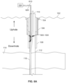
FIGS. 6A-6D are schematic illustrations of a wellbore system that includes the example tool of FIGS. 5A and 5B.
FIG. 7 is a schematic illustration of an example tool for freeing a stuck pipe in wellbore.
FIGS. 8A and 8B are schematic top views of a wellbore system that includes the example tool of FIG. 7 .
FIGS. 9A-9C are schematic illustrations of a wellbore system that includes an example tool for freeing a stuck pipe in a wellbore.
FIG. 10 is a schematic illustration of an example control system for a tool for freeing a stuck pipe from a wellbore according to the present disclosure.
DETAILED DESCRIPTION
The present disclosure describes tools and systems for freeing a stuck pipe from a wellbore.
FIG. 1 is a schematic illustration of an example wellbore system 100 including a drillstring 110. The drillstring 110 is operable to apply torque to a drill bit to form a wellbore 112, as well as convey formation fluid in the wellbore 112 to the terranean surface 102.
Although not shown, a drilling assembly deployed on the terranean surface 102 may be used in conjunction with the drillstring 110 to form the wellbore 112 through a particular location in the subterranean zone 114. The wellbore 112 may be formed to extend from the terranean surface 102 through one or more geological formations in the Earth. One or more subterranean formations, such as subterranean zone 114, are located under the terranean surface 102. One or more wellbore casings, such as surface casing 106 and intermediate casing 108, may be installed in at least a portion of the wellbore 112.
Although shown as a wellbore 112 that extends from land, the wellbore 112 may be formed under a body of water rather than the terranean surface 102. For instance, in some embodiments, the terranean surface 102 may be a surface under an ocean, gulf, sea, or any other body of water under which hydrocarbon-bearing, or water-bearing, formations may be found. In short, reference to the terranean surface 102 includes both land and underwater surfaces and contemplates forming or developing (or both) one or more wellbores 112 from either or both locations.
Generally, the wellbore 112 may be formed by any appropriate assembly or drilling rig used to form wellbores or boreholes in the Earth. A drilling assembly may use traditional techniques to form such wellbores or may use nontraditional or novel techniques. Although shown as a substantially vertical wellbore (for example, accounting for drilling imperfections), the wellbore 112, in alternative aspects, may be directional, horizontal, curved, multi-lateral, or other forms other than merely vertical.
One or more tubular casings may be installed in the wellbore 112 during portions of forming the wellbore 112. As illustrated, the wellbore 112 includes a conductor casing 104, which extends from the terranean surface 102 shortly into the Earth. A portion of the wellbore portion 112 enclosed by the conductor casing 104 may be a large diameter borehole.
Downhole of the conductor casing 104 may be the surface casing 106. The surface casing 106 may enclose a slightly smaller borehole and protect the wellbore 112 from intrusion of, for example, freshwater aquifers located near the terranean surface 102. The wellbore 112 may then extend vertically downward. This portion of the wellbore 112 may be enclosed by the intermediate casing 108. In some aspects, the wellbore 112 can include an open hole portion (for example, with no casing present).
The drillstring 110 may be made up of multiple sections of drill pipe 116. As can be seen in FIG. 1 , the drillstring 110 includes a section of drill pipe 116 that is stuck against a surface of the wellbore 112.
FIG. 2 depicts a top view of a wellbore 212 with a section of drill pipe 216 stuck in the wellbore 212. As can be seen in FIG. 2 , in some implementations, a section of drill pipe 216 can become lodged against a surface of the wellbore 212 during drilling operations, which prevents vertical and/or rotational movement of the drill pipe 216 within the wellbore 212, thus causing the drill pipe 216 to become “stuck” within the wellbore 212. In order to continue drilling operations within the wellbore 212, the stuck drill pipe 216 must be freed from the surface of the wellbore 212 to allow for movement of the drill pipe 216.
FIGS. 3A-3C are schematic illustrations of an example implementation of a tool 300 for freeing a stuck section of drill pipe in a wellbore. For example, in some aspects, the pipe freeing tool 300 may be used in the wellbore system 100 to free a stuck portion of the drill pipe 116 from the surface of the wellbore 112.
As can be seen in FIG. 3A, the illustrated implementation of the pipe freeing tool 300 includes a downhole conveyance 302 and a side arm 304 coupled to the downhole conveyance 302 near an end of the downhole conveyance 302. In some implementations, as depicted in FIGS. 3A-3C, the downhole conveyance 302 is a tubular pipe. In some implementations, the downhole conveyance 302 is a tubular pipe having an outer diameter that is smaller than the inner diameter of the stuck drill pipe 116 that the pipe freeing tool 300 is being used to free from the wellbore 112.
As depicted in FIGS. 3A-3C, a side arm 304 is coupled to the surface of the downhole conveyance 302 of the pipe freeing tool 300. In some implementations, the side arm 304 is pivotally coupled to the downhole conveyance 302 of the pipe freeing tool 300. In some implementations, the side arm 304 is configured pivot between a retracted position 306, as depicted in FIG. 3B, and an extended position 308, as depicted in FIG. 3C. The side arm 304 can be coupled to the downhole conveyance 302 using one or more mechanical connectors, such as a hinges, pivot joints, ball joints, etc. In some implementations, the side arm 304 and downhole conveyance 302 are one integral, unitary body. The side arm 304 can be made of any suitable material, including, for example, metal or expandable material.
In some implementations, the longitudinal axis 320 of the side arm 304 is substantially parallel with the longitudinal axis 322 of the downhole conveyance 302 when the side arm 304 is in the fully retracted position 306, as depicted in FIG. 3B. In some implementations, the longitudinal axis 320 of the side arm 304 is substantially perpendicular with the longitudinal axis 322 of the downhole conveyance 302 when the side arm 304 is in the fully extended position 308, as depicted in FIG. 3C.
In some implementations, the side arm 304 can be activated by a power cable (not shown) to pivot between the retracted position 306 and an extended position 308. For example, the side arm 304 can be coupled to a control system (not shown) on the terranean surface 102 by a power cable, and the control system can be used to activate the side arm 304 of the pipe freeing tool 300 into the retracted position 306 or the extended position 308. In some implementations, an operator can use a control system to activate the side arm 304 to position the longitudinal axis 320 of the side arm along to a particular angle 324 relative to the longitudinal axis 322 of downhole conveyance 302. In some implementations, the position of the side arm 304 relative to the downhole conveyance 302 can be adjusted in increments of about 10 degrees. In some implementations, the side arm 304 can be positioned such that the angle 324 between the longitudinal axis 320 of the side arm 304 and the longitudinal axis 322 of the downhole conveyance 302 ranges from about 0 degrees to about 90 degree. As will be described in further detail herein, the side arm 304 can be activated to pivot between the retracted position 306 and the extended position 308 in order to apply a force to a stuck drill pipe 116 and free the stuck drill pipe 116 from the wellbore 112.
In some implementations, the pipe freeing tool 300 includes a circulating valve 360 that can be used to pump fluids, such as lubricant fluids or acid, into the wellbore 112 to help assist in freeing the drill pipe 116. In some implementations, fluids, such as lubricant pills or acid, are pumped through the drillstring 110 into the wellbore 112 to help assist in freeing the drill pipe 116. In some implementations, as depicted in FIGS. 3A-3C, the circulating valve 360 is installed above the side arm 306.
An example operation of the pipe freeing tool 300 is described with reference to FIGS. 4A-4D.
In response to determining that a section of drill pipe 116 has become stuck against the side of the wellbore 112, the pipe freeing tool 300 can be conveyed through the annulus of the wellbore 112 to perform operations to free the stuck drill pipe 116. For example, as depicted in FIG. 4A, the downhole conveyance 302 can be lowered downhole through the annulus of the wellbore 112 to position the pipe freeing tool 300 between an open hole portion of the wellbore 112 and a section of the stuck drill pipe 116 proximate the stuck point. In some implementation, the pipe freeing tool 300 is positioned within the wellbore 112 as close as possible to the stuck point.
In some implementations, the pipe freeing tool 300 is continually lowered downhole into the wellbore 112 until it is determined that the pipe freeing tool 300 is positioned proximate the stuck point of the section of stuck drill pipe 116. In some implementations, the pipe freeing tool 300 is coupled to a surface weight indicator 404 that monitors the weight of the pipe freeing tool 300 as it is lowered through the wellbore 112. The weight of the pipe freeing tool 300 as measured by the weight indicator 404 will decrease once the pipe freeing tool 300 contacts the stuck section of drill pipe 116. Thus, by monitoring a weight indicator 404 coupled to the pipe freeing tool 300, an operator can determine when the pipe freeing tool 300 is positioned against the section of stuck drill pipe 116 proximate the stuck point. In some implementations, the weight indicator 404 is a Martin-Decker indicator. In some implementations, the pipe freeing tool 300 includes one or more sensors that can be used to determine whether the pipe freeing tool 300 is positioned against the section of stuck drill pipe 116 proximate the stuck point. In some implementations, a free point indicator tool is inserted downhole on a wireline to determine the stuck point prior to deployment of the pipe freeing tool 300 within the wellbore 112.
Once the pipe freeing tool 300 is positioned within the wellbore 112 in contact with the drill pipe 116 proximate the stuck point, the side arm 304 of the pipe freeing tool 300 can be activated to pivot and apply a force to the stuck drill pipe 116 in order to free the stuck drill pipe 116 from the surface of the wellbore 112. In some implementations, the pipe freeing tool 300 can be attached to a power cable 402, which can be used to active the side arm 304 to pivot inward or outward from the housing 102. As depicted in FIG. 4A, in some implementations, the pipe freeing tool 300 is communicably coupled to a control system 124 via the power cable 402, and the control system 124 can be used to activate the pipe freeing tool 300.
In some implementations, activating the pipe freeing tool 300 causes the side arm 304 to pivot away from the downhole conveyance 302 into an extended position 308, which causes the side arm 304 to push against the section of the stuck drill pipe 116 to push the stuck drill pipe 116 away from the surface of the wellbore 112. For example, as depicted in FIG. 4A, the pipe freeing tool 300 can be lowered into the wellbore 112 with the side arm 304 of the pipe freeing tool 300 in a retracted position 306 and the pipe freeing tool can be positioned within the wellbore 112 such that the side arm 304 of the pipe freeing tool 300 contacts the drill pipe 116 proximate the stuck point. Referring to FIG. 4B, once the pipe freeing tool 300 is positioned within the wellbore 112, the side arm 304 can be activated via the power cable 402 to pivot outwards to an extended position 308. As the side arm 304 pivots from the retracted position 306 depicted in FIG. 4A to the extended position 308 depicted in FIG. 4B, the side arm 304 applies a pushing force to the drill pipe 116 towards the center of the wellbore 112, which causes the section of stuck drill pipe 116 to be pushed away from the surface of the wellbore 112. As a result, the section of stuck drill pipe 116 is freed from the surface of the wellbore, as depicted in FIG. 4B.
In some implementations, the side arm 304 continues to pivot outwards until the side arm 304 is in a fully extended position 308.
Referring to FIG. 4C, in some implementations, the side arm 304 latches onto the drill pipe 116, and activating the pipe freeing tool 300 causes the side arm 304 to pull the stuck drill pipe 116 away from the surface of the wellbore 112. For example, as depicted in FIG. 4C, the pipe freeing tool 300 can be lowered into the wellbore 112 with the side arm 304 in an extended position 308 and the pipe freeing tool 300 can be positioned within the wellbore 112 such that the side arm 304 of the pipe freeing tool 300 latches onto or otherwise attaches to a portion of the drill pipe 116 proximate the stuck point. Referring to FIG. 4D, once the pipe freeing tool 300 is positioned within the wellbore 112 and the side arm 304 of pipe freeing tool 300 is latched onto or otherwise coupled to the stuck drill pipe 116, the side arm 304 can be activated via the power cable 402 to pivot inwards towards the downhole conveyance 302, as depicted in FIG. 4D. As the side arm 304 pivots from the extended position 308 depicted in FIG. 4C to the retracted positioned depicted in FIG. 4D while coupled to the drill pipe 116, the side arm 304 pulls the drill pipe 116 towards the center of the wellbore 112, which causes the section of stuck drill pipe 116 to be pulled away from the surface of the wellbore 112. As a result, the section of stuck drill pipe 116 is freed from the surface of the wellbore 112, as depicted in FIG. 4D. In some implementations, the side arm 304 continues to pivot inwards until the side arm 304 is in a fully retracted position 306 against the downhole conveyance 302.
Once the section of stuck drill pipe 116 has been freed from the surface of the wellbore 112, the pipe freeing tool 300 can be raised out of the wellbore 112 and drilling operations within the wellbore can proceed.
FIGS. 5A and 5B are schematic illustrations of example implementation of another tool 500 for freeing a stuck section of drill pipe from the surface of a wellbore. For example, in some aspects, the pipe freeing tool 500 may be used in the wellbore system 100 to free a stuck portion of the drill pipe 116 from the surface of the wellbore 112.
As can be seen in FIGS. 5A and 5B, the illustrated implementation of the pipe freeing tool 500 includes a jack 502 and a set of wheels 504, 506, 508, 510 coupled to the jack 502.
The jack 502 includes a base 512, a platform 514, and a set of lift arms 520, 522, 524, 526. As can be seen in FIGS. 5A and 5B, the lift arms 520, 522, 524, 526 are each pivotally coupled the base 512 at a first end to and are pivotally coupled to the platform 514 at a second, opposite end. The lift arms 520, 522, 524, 526 can be coupled to the downhole conveyance 302 using one or more mechanical fasteners, such as a screws, pins, etc.
As depicted in FIGS. 5A and 5B, each of the wheels 504, 506, 508, 510 are coupled to a respective corner of the base 512. As will be described in further detail herein, the wheels 504, 506, 508, 510 can enable the pipe freeing tool 500 to traverse along the surface of a wellbore to position the pipe freeing tool 500 proximate a stuck drill pipe. The wheels 504, 506, 508, 510 can be made of any suitable material, including, for example, rubber.
The pipe freeing tool can be raised and lowered between a lowered position and a raised position to apply a force to a stuck drill pipe. For example, as depicted in FIG. 5A, the lift arms 520, 522, 524, 526 be lowered to position the platform 514 of the pipe freeing tool 500 into a lowered position 530 against or close to the base 512 of the pipe freeing tool 500. As depicted in FIG. 5B, the lift arms 520, 522, 524, 526 can be raised to position the platform 514 of the pipe freeing tool 500 into a raised position 530 above the base 512 of the pipe freeing tool 500.
In some implementations, in additional to being raised and lowered, the platform 514 of the jack 502 can be rotated side to side about the base 512. In some implementations, the platform 514 can be rotated up to 180 degrees about the base 512. In some implementations, the rotation of the platform 514 about the base 512 is controlled by a control system (for example, control system 124 of FIGS. 6A-6D). Rotating the platform 514 about the base 512 can allow for improved positioning of the pipe freeing tool 500 against a stuck drill pipe 116 within the wellbore 112.
In some implementations, the pipe freeing tool 500 also includes a sand bailer 550 attached to the base 512 of the jack 502 and configured to remove debris from the wellbore 112. In some implementations, the sand bailer 550 is positioned on a front portion of the pipe freeing tool 500 and removes debris from the wellbore 112 in front of the pipe freeing tool 500 as the pipe freeing tool 500 traverses the wellbore 112. By removing debris from the wellbore 112, the sand bailer 550 allows for the pipe freeing tool 500 to travel more smoothly along the wellbore 112.
An example operation of the pipe freeing tool 500 is described with reference to FIGS. 6A-6D.
In response to determining that a section of drill pipe 116 has become stuck against the side of the wellbore 112, the pipe freeing tool 500 can be conveyed through the annulus of the wellbore 112 to perform operations to free the stuck drill pipe 116. For example, as depicted in FIG. 6A, the pipe freeing tool 500 can be lowered downhole through the annulus of the wellbore 112 to position the pipe freeing tool 500 between an open hole portion of the wellbore 112 and the stuck drill pipe 116 proximate the stuck point. In some implementation, the pipe freeing tool 500 is positioned within the wellbore 112 as close as possible to the stuck point
As depicted in FIGS. 6A-6D, in some implementations, the pipe freeing tool 500 is coupled to a downhole conveyance 610 and is lowered into the wellbore 112 using the downhole conveyance 610. In some implementations, the downhole conveyance 610 may be a tubular work string made up of multiple tubing joints. For example, a tubular work string typically consists of sections of steel pipe, which are threaded so that they can interlock together. In alternative embodiments, the downhole conveyance 610 may be a wireline. In some examples, the downhole conveyance 610 may be an e-line. In some implementations, the downhole conveyance 610 may be coiled tubing.
In addition to using a downhole conveyance 610 to lower the pipe freeing tool 500 into the wellbore 112, the wheels 504, 506, 508, 510 of the pipe freeing tool 500 allow the pipe freeing tool 500 to roll along the surface of the wellbore 112. By rolling the pipe freeing tool 500 along the surface of the wellbore 112 using wheels 504, 506, 508, 510, the risk of damage to the pipe freeing tool 500 can be minimized.
As previously discussed, in some implementations, the pipe freeing tool 500 also includes a sand bailer 550 configured to remove debris from the wellbore 112. For example, the sand bailer 550 can be positioned on a front portion of the pipe freeing tool 500 and can be operated as the pipe freeing tool 500 is lowered into the wellbore 112 in order to remove debris from the wellbore 112 in the path of travel of the pipe freeing tool 500. By removing debris from the wellbore 112, the sand bailer 550 allows for the pipe freeing tool 500 to travel more smoothly along the wellbore 112, further reducing the risk of damage to the pipe freeing tool 500.
In some implementations, the pipe freeing tool 500 is continually lowered downhole into the wellbore 112 and rolled along the surface of the wellbore 112 until it is determined that the pipe freeing tool 500 is positioned proximate the stuck point of the drill pipe 116. In some implementations, a caliber (not shown) coupled to the pipe freeing tool 500 can be used to determine that the pipe freeing tool 500 is positioned proximate the stuck point of the stuck drill pipe 116. As depicted in FIG. 6A, in some implementations, the pipe freeing tool 500 is lowered downhole through the wellbore 112 in the lowered position 530 with the lift arms 520, 522, 524, 526 lowered.
As depicted in FIG. 6B, once the pipe freeing tool 500 is positioned within the wellbore 112 proximate the stuck point of the drill pipe 116, the jack 502 of the pipe freeing tool 500 can be activated to raise the lift arms 520, 522, 524, 526 and position the jack 502 in the raised position 532. In some implementations, the jack 502 of the pipe freeing tool 500 is activated hydraulically. In some implementations, the jack 502 of the pipe freeing tool 500 is activated mechanically. For example, in some implementations, once the pipe freeing tool 500 is properly positioned in the wellbore 112 proximate the stuck point of the drill pipe 116, additional weight is added to the pipe freeing tool 500 and rotation is applied to the pipe freeing tool 500 using the downhole conveyance 600 to activate the jack 502 and raise the lift arms 520, 522, 524, 526, which raises the jack 502 from a lowered position 530 to a raised position 532. In some implementations, the jack 502 is activated and raised from the lowered position 530 to the raised position 532 by dropping a ball through an annulus of a downhole conveyance 610 coupled to the pipe freeing tool 500, which increases the pressure within the downhole conveyance 610 and activates the jack 502 into a raised position 532. In some implementations, the jack 502 is activated and raised from the lowered position 530 to the raised position 532 using a control line 620 coupled to the pipe freeing tool 500. In some implementations, the control line 620 communicably couples the pipe freeing tool 500 to a control system 124, and the control system 124 can be used to initiate activation of the jack 502. In some implementations, the control system 124 can control electrical power and/or hydraulics supplied to the pipe freeing tool 500.
Referring to FIG. 6B, as the jack 502 is activated and the lift arms 520, 522, 524, 526 raise the jack 502 from a lowered position 530 to a raised position 532, the platform 514 of the jack 502 contacts and applies a force to the drill pipe 116 proximate the stuck point. As the lift arm 520, 522, 524, 526 continue to be raised, the platform 514 of the jack 502 pushes the stuck drill pipe 116 away from the surface of the wellbore 112 to free the stuck drill pipe 116, as depicted in FIG. 6B.
In some implementations, the lift arms 520, 522, 524, 526 continue to raise until the platform 514 of the jack 502 is in a fully raised position 532. In some implementations, an operator can use the control system 124 to set a particular height for the platform 514 relative to the base 512 of the jack 502, and, once the jack 502 is activated, the lift arms 520, 522, 524, 526 continue to raise until the platform 514 is positioned at the selected height relative to the base 512.
Referring to FIGS. 6C and 6D, in some implementations, the jack 502 is lowered into the wellbore 112 in a raised position 532 and couples to the stuck drill pipe 116 to apply a pulling force to the drill pipe 116 to free the stuck drill pipe 116 from the surface of the wellbore 112. For example, as depicted in FIG. 6C, in some implementations, the pipe freeing tool 500 is lowered downhole through the wellbore 112 in the raised position 532 with the lift arms 520, 522, 524, 526 raised. The pipe freeing tool 500 can be continually lowered through the wellbore 112 using the downhole conveyance 610 until it is determined (for example, using a caliber) that the pipe freeing tool 500 is positioned proximate the stuck point of the stuck drill pipe 116 and the platform 514 of the jack 502 is in contact with the stuck drill pipe 116.
Once the pipe freeing tool 500 is lowered into the wellbore 112 with the jack 502 in an raised position 532 and positioned within the wellbore 112 such that platform 514 of the jack 502 is in contact with the stuck drill pipe 116, the platform 314 can latch onto or otherwise couple to a portion of the stuck drill pipe 116 proximate the stuck point.
As depicted in FIG. 6D, once the pipe freeing tool 500 is positioned within the wellbore 112 proximate the stuck point and the platform 514 is coupled to the stuck drill pipe 116, the jack 502 of the pipe freeing tool 500 can be activated to lower the lift arms 520, 522, 524, 526 of the jack 502, which lowers the platform 514 of the jack 502 into a lowered position 530. As the lift arm 520, 522, 524, 526 continue to be lowered, the platform 514 of the jack 502 coupled to the drill pipe 116 pulls the stuck drill pipe 116 away from the surface of the wellbore 112 to free the stuck drill pipe 116 from the surface of the wellbore 112, as depicted in FIG. 6D.
In some implementations, the lift arms 520, 522, 524, 526 continue to lower until the platform 514 of the jack 502 is in a fully lowered position 530. In some implementations, an operator can use the control system 124 to set a particular height for the platform 514 relative to the base 512 of the jack 502, and, once the jack 502 is activated, the lift arms 520, 522, 524, 526 continue to lower until the platform 514 is at the selected height relative to the base 512.
As the lift arms 520, 522, 524, 526 are raised or lowered during activation of the jack 502 within the wellbore 112, the wheels 504, 506, 508, 510 of the pipe freeing tool 500 remain in contact with the wellbore 112. In addition, the wheels 504, 506, 508, 510 of the pipe freeing tool 500 can function to reduce the amount of friction between the pipe freeing tool 500 and the wellbore 112.
Once the section of stuck drill pipe 116 has been freed from the surface of the wellbore 112, the pipe freeing tool 500 can be raised out of the wellbore 112 and drilling operations within the wellbore can proceed. In some implementations, the platform 514 of the pipe freeing tool 500 is lowered into the lowered position 530 prior to raising the pipe freeing tool 500 uphole out of the wellbore 112.
While the pipe freeing tool 500 has been depicted as including four wheels 504, 506, 508, 510, other numbers of wheels can be included in the pipe freeing tool 500. In addition, while the pipe freeing tool 500 has been depicted as including four lift arms 520, 522, 524, 526, other numbers of lift arms can be included in the pipe freeing tool 500
FIG. 7 is schematic illustration of a top view of an example implementation of another tool 700 for freeing a stuck section of drill pipe from the surface a wellbore. For example, in some aspects, the pipe freeing tool 700 may be used in the wellbore system 100 to free a stuck portion of the drill pipe 116 from the surface of the wellbore 112.
As can be seen in FIG. 7 , the illustrated implementation of the pipe freeing tool 700 includes a body 702 and a set of arms 712, 714, 716, 718 (or more or fewer arms) coupled to and projecting from the body 702. The body 702 of the pipe freeing tool 702 can be made of any suitable material, including, for example, metal or expandable materials.
As will be described in further detail herein, each of the arms 712, 714, 716, 718 of the pipe freeing tool 700 is configured to extend outward from the body 702 of the pipe freeing tool 700 into an extended position in order to apply a force to a stuck drill pipe 116 and push the stuck drill pipe 116 away from the surface of the wellbore 112. In some implementations, the length of the arms 704, 706 708, 710 of the pipe freeing tool 700 is sized based on the size of the wellbore 112 that the pipe freeing tool 700 is configured to be deployed within. For example, pipe freeing tools 700 configured to be used in wider wellbores 112 can have longer arms 712, 714, 716, 718, whereas pipe freeing tools 700 configured to be used in narrower wellbores can have shorter arms 712, 714, 716, 718. The fully extended length of the arms 712, 714, 716, 718 can range from about 0.5 in to approximately the diameter of the wellbore. The arms 712, 714, 716, 718 can be made of any suitable material, including, for example, metal or expandable materials.
As depicted in FIG. 7 , each arm 712, 714, 716, 718 of the pipe freeing tool 700 is coupled to the body 702 of the pipe freeing tool 500 at a first end and includes a cutting edge 722, 724, 726, 728 at a second, opposite end. The cutting edges 722, 724, 726, 728 of the arms 712, 714, 716, 718 of the pipe freeing tool 700 can be configured to pierce through the wall of a stuck drill pipe. In some implementations, the cutting edges 722, 724, 726, 728 are formed onto ends of the arms 712, 714, 716, 718 such that the cutting edges 722, 724, 726, 728 are integral with the arms 712, 714, 716, 718. The cutting edges 722, 724, 726, 728 can be made of any suitable material, including, for example, ceramic materials and ceramic composite materials.
An example operation of the pipe freeing tool 700 is described with reference to FIGS. 8A and 8B.
In response to determining that a section of drill pipe 116 along a drillstring has become stuck against the side of the wellbore 112, the pipe freeing tool 700 can be conveyed through the annulus of the drillstring (for example, drillstring 110 of FIG. 1 ) until the pipe freeing tool 700 is positioned within the annulus 802 of the stuck drill pipe 116. For example, as depicted in FIG. 8A, the pipe freeing tool 700 can be conveyed through the annulus of the drillstring until the pipe freeing tool 700 is positioned within the annulus 802 of the stuck drill pipe 116 proximate the stuck point. As can be seen in FIG. 8A, as the pipe freeing tool 700 is being lowered downhole into the annulus 802 of the stuck drill pipe 116, the arms 712, 714, 716, 718 of the pipe freeing tool 700 are maintained in a retracted position 730.
In some implementations, the body 702 of the pipe freeing tool 700 is coupled to a downhole conveyance 810 and the pipe freeing tool 700 is lowered into the wellbore 112 using the downhole conveyance 810. For example, in some implementations, the downhole conveyance 810 coupled to the body 702 of the pipe freeing tool 700 is a pipe with an outer diameter that is smaller than the inner diameter of the stuck drill pipe 116, and the downhole conveyance 810 is used to lower the pipe freeing tool 700 downhole through the annulus of the drillstring into the annulus 802 of the stuck drill pipe 116. In some implementations, the downhole conveyance 810 used to convey the pipe freeing tool 700 may be a tubular work string made up of multiple tubing joints. For example, a tubular work string typically consists of sections of steel pipe, which are threaded so that they can interlock together. In alternative embodiments, the downhole conveyance 810 used to convey the pipe freeing tool 700 may be a wireline. In some examples, the downhole conveyance 810 used to convey the pipe freeing tool 700 may be an e-line. In some implementations, the downhole conveyance 810 used to convey the pipe freeing tool 700 may be coiled tubing.
The pipe freeing tool 700 can be continually lowered downhole through the annulus of the drillstring until it is determined that the pipe freeing tool 700 is positioned within the annulus 802 of the stuck drill pipe 116 proximate the stuck point of the stuck drill pipe 116. In some implementations, the pipe freeing tool 700 is coupled to a surface weight indicator (for example, surface weight indicator 404 of FIGS. 4A-4D) that monitors the weight of the pipe freeing tool 700 as it is lowered into the annulus 802 of the stuck drill pipe 116. Upon the pipe freeing tool 700 being positioned within the stuck drill pipe 116, the weight of the pipe freeing tool 700 as measured by the weight indicator will decrease. Thus, by monitoring a weight indicator coupled to the pipe freeing tool 700, an operator can determine when the pipe freeing tool 700 is positioned within the section of stuck drill pipe 116 proximate the stuck point. In some implementations, the weight indicator is a Martin-Decker indicator. In some implementations, a free point indicator tool is run downhole on a wireline to determine the stuck point prior to positioning the pipe freeing tool 700 within the wellbore 112.
Once the pipe freeing tool 700 is positioned within the annulus 802 of the stuck drill pipe 116 proximate the stuck point with the arms 712, 714, 716, 718 in the retracted position 730, as depicted in FIG. 8A, the arms 712, 714, 716, 718 of the pipe freeing tool 700 can be activated to extend outward from the body 702 of the pipe freeing tool 700. As can be seen in FIG. 8B, as the arms 712, 714, 716, 718 extend outward from the body 702 of the pipe freeing tool 700, the cutting edges 722, 724, 726, 728 on the ends of each of the arms 712, 714, 716, 718 pierce through the wall of the stuck drill pipe 116, allowing the arms 712, 714, 716, 718 to extend through the wall of the stuck drill pipe 116 and outwards towards the surface of the wellbore 112. In some implementations, the arms 712, 714, 716, 718 are telescoping arms that telescope outwards from the body 702 of the pipe freeing tool 700 from a retracted position 730, as depicted in FIG. 8A, to an extended position 732, as depicted in FIG. 8B.
In some implementations, the arms 712, 714, 716, 718 of the pipe freeing tool 700 are activated to extend from a retracted position 730 to an extended position 732 using a power cable coupled to the pipe freeing tool 700. In some implementations, the arms 712, 714, 716, 718 of the pipe freeing tool 700 are activated to extend from a retracted position 730 to an extended position 732 by rotating a downhole conveyance coupled to the pipe freeing tool 700, which cause the arms 712, 714, 716, 718 to extend outward from the body 702 of the pipe freeing tool 700.
In some implementations, the arms 712, 714, 716, 718 of the pipe freeing tool 700 continue to extend outward until the cutting edge 722, 724, 726, 728 of each of the arms 712, 714, 716, 718 contacts the surface of the wellbore 112. In some implementations, the arms 712, 714, 716, 718 continue to extend outward until the arms 712, 714, 716, 718 are positioned in a fully extended position 732, as depicted in FIG. 8B. For example, as previously discussed, in some implementations, the length of the arms 704, 706 708, 710 of the pipe freeing tool 700 is sized based on the size of the wellbore 112 that the pipe freeing tool 700 is configured to be deployed within. As such, when the arms 712, 714, 716, 718 are in the fully extended position 732, the cutting edge 722, 724, 726, 728 of each of the arms 712, 714, 716, 718 contacts the surface of the wellbore 112, as depicted in FIG. 8B. In some implementations, an operator can use a control system to set a particular length for each of the arms 712, 714, 716, 718 to extend outward from the body 702 in the fully extended position 732 (for example, based on the size of the wellbore 112), and, once activated, the arms 712, 714, 716, 718 continue to extend outward from the body 702 until each arm 712, 714, 716, 718 has extended to the predetermined length relative to the body 702 of the pipe freeing tool 700. In some implementations, the predetermined extended length of the arms 712, 714, 716, 718 relative to the body 702 is based on the size of the wellbore 112.
As one or more of the arms 712, 714, 716, 718 extend outward and contact the surface of the wellbore 112, the arms 712, 714, 716, 718 contacting the wellbore will begin to apply a pushing force against the wall of the drill pipe 116, which pushes the stuck drill pipe 116 away from the surface of the wellbore 112 towards the center of the wellbore 112. For example, as depicted in FIG. 8A, arm 718 of the pipe freeing tool 700 is initially positioned closest to the surface of the wellbore 112 of arms 712, 714, 716, 718. As a result, as the arms 712, 714, 716, 718 of the pipe freeing tool 700 are activated and extend outward from the body 702, arm 718 contacts the wellbore 112 before arms 712, 714, 716 contact the wellbore 112. As arm 718 continues to extend outwards after contacting the wellbore 112, arm 718 applies a pushing force to the wall of the stuck pipe 116 that causes the stuck pipe 116 to be freed from the surface of the wellbore 112 and move towards the center of the wellbore 112, as depicted in FIG. 8B.
Once the section of stuck drill pipe 116 has been freed from the surface of the wellbore 112, the pipe freeing tool 700 can be raised out of the wellbore 112 and drilling operations within the wellbore can proceed. In some implementations, the arms 712, 714, 716, 178 of the pipe freeing tool 700 are returned to the retracted position 730, as shown in FIG. 8A, prior to raising the pipe freeing tool 700 uphole out of the wellbore 112.
FIGS. 9A-9C are schematic illustrations of an example implementation of another tool 900 for freeing a stuck section of drill pipe from the surface of a wellbore.
As can be seen in FIG. 9A, the illustrated implementation of the pipe freeing tool 900 includes a series of expandable disc elements 902, 904, 906, 908 positioned circumferentially along and coupled to one or more drill pipes 916 of a drillstring 910. Each of the expandable disc elements 902, 904, 906, 908 can be made of any expandable metal material. In some embodiments, the expandable disc elements 902, 904, 906, 908 are each made of an expandable metal material capable of withstanding high forces.
The expandable disc elements 902, 904, 906, 908 are each configured to be selectively activated into an expanded configuration in order to free stuck drill pipe 936 along the drillstring 910 from the surface of the wellbore 112. For example, as depicted in FIG. 9A, each of the expandable disc elements 902, 904, 906, 908 includes a respective internal seat 912, 914, 916, 918 that is configured to receive a ball of a particular size or diameter, which activates the respective expandable disc element 902, 904, 906, 908 into an expanded configuration. As can be seen in FIG. 9A, the width of the seat 912, 914, 916, 918 of each expandable disc element 902, 904, 906, 908 is different from the width of the seat 912, 914, 916, 918 of the other disc elements 902, 904, 906, 908 along the drillstring 910.
In some implementations, the uppermost (furthest uphole) disc element has the widest seat and the bottommost (furthest downhole) disc element has the narrowest seat, with the seats of the expandable disc elements between the uppermost element and lowermost element having seats that decrease in width for each successive element further downhole. As described below, in some implementations, the bottommost (furthest downhole) expandable disc element has the narrowest seat such that a small ball corresponding to the seat size of the bottommost expandable disc element can be dropped through the annulus without seating until it reaches the bottommost expandable disc element. As such, any number of the expandable disc elements 902, 904, 906, 908 of the pipe freeing tool 900 can be selectively and individually expanded. For example, as depicted in FIG. 9A, uppermost expandable disc element 902 has the widest seat 912, lowermost expandable disc element 908 has the narrowest seat 918, expandable disc element 914 has a seat 904 that is wider than the seats 916, 918 of disc elements 906 and 908, but narrower that seat 912, and disc element 916 has a seat that is wider than seat 918 of disc element 908, but narrower than seats 912, 914 of the expandable disc elements 902, 904.
An example operation of the pipe freeing tool 900 is described with reference to FIGS. 8A and 8B.
During drilling operations using a drillstring 910 coupled to the pipe freeing tool 900, an operator may determine that a section of drill pipe 936 along the drillstring 910 has become stuck against the surface of the wellbore 112, as depicted in FIG. 9A. In some implementations, a weight indicator (such as weight indicator 404 of FIGS. 4A-4D) or other downhole tool can be used to determine the depth of the stuck point within the wellbore 112. As can be seen in FIG. 9A, during normal drilling operations, each of the expandable disc elements 902, 904, 906, 908 is maintained in an unexpanded configuration 930.
In response to determining that a section of drill pipe 936 along the drillstring 910 has become stuck against the side of the wellbore 112, one or more of the expandable disc elements 902, 904, 906, 908 proximate the stuck point can be activated into an expanded configuration to free the stuck drill pipe 936 from the surface of the wellbore 112. For example, as depicted in FIG. 9B, expandable disc elements 906 and 908 proximate the stuck point of the stuck drill pipe 936 can be activated to expand outward from the drill pipe 936 into an expanded configuration 932.
As previously discussed, in some implementations, each of the expandable disc elements 902, 904, 906, 908 is expanded by seating a ball with a size corresponding to the width of the internal seat 912, 904, 906, 908 of the respective expandable disc element 902, 904, 906, 908 into the seat 912, 904, 906, 908 of the respective expandable disc element 902, 904, 906, 908. For example, as depicted in FIG. 9B, in order to active expandable disc elements 906 and 908, a first ball 920 with a diameter corresponding to the width of the internal seat 918 of expandable disc element 908 is dropped through the annulus of the drillstring 910 and seats within the internal seat 918 of expandable disc element 908. The diameter of the first ball 920 used to activate expandable disc element 908 is smaller than the width of the internal seats 912, 914, 916 of the other expandable disc elements 902, 904, 906, and, as a results, passes the through the annulus and seat 912, 914, 916 of each of the other expandable disc elements 902, 904, 906 without expanding the other expandable disc elements 904, 906, 908. By seating the first ball 920 within the seat 919 of expandable disc element 908 and then applying a pressure to the wellbore from the surface, the pressure within the expandable disc element 908 increases above a threshhold pressure and causes the expandable disc element 908 to expand outward into an circular expanded configuration 932, as can be seen in FIG. 9B.
Still referring to FIG. 9B, a second expandable disc element located uphole of the activated expandable disc element 908 can also be activated into an expanded configuration, if necessary, to free the stuck drill pipe 936. For example, a second ball 922 with a diameter corresponding to the width of the internal seat 916 of expandable disc element 906 is dropped through the annulus of the drillstring 910 and seats within the internal seat 916 of expandable disc element 906. The diameter of the second ball 922 used to activate expandable disc element 906 is smaller than the width of the internal seats 912, 914 of the expandable disc elements 902, 904 uphole of expandable disc element 906. As a result, the second ball 922 passes the through the annulus and seat 912, 914 of each of the other uphole expandable disc elements 902, 904 without expanding the uphole expandable disc elements 902, 904. By seating the second ball 922 within expandable disc element 906 and then applying a pressure to the wellbore from the surface, the pressure within the expandable disc element 906 increases above a threshold pressure and causes the expandable disc element 906 to expand outward into a circular expanded configuration 932, as can be seen in FIG. 9B.
As can be seen in FIG. 9B, as the activated expandable disc elements 906, 908 each expand outwards, the surface of each of the expandable disc elements 906, 908 presses against the surface of the wellbore 112. As the activated expandable disc elements 906, 908 continue to expand outward and press against the surface of the wellbore 112, the activated expandable disc elements 906, 908 apply a side force the stuck drill pipe 936 and push the stuck drill pipe 936 towards the center of the wellbore 112. As a result, the stuck drill pipe 936 is freed from the surface of the wellbore 112, as depicted in FIG. 9B. As can be seen in FIG. 9B, in some implementations, the expandable disc elements 902, 904, 906, 908 are configured to expand to a diameter that corresponds to the diameter of the wellbore 112.
As depicted in FIG. 9C, in some implementations, once the section of stuck drill pipe 116 has been freed from the surface of the wellbore 112, the activated expandable disc elements 906, 908 are returned to the unexpanded configuration 930. For example, in some implementations, after freeing the stuck drill pipe 916 from the surface of the wellbore 112, the pressure within the wellbore 112 is increased to a threshold pressure that exceeds the pressure within the activated expandable disc element 906, 908, which causes the internal seats 912, 914, 916, 918 to rupture, which in turn causes the activated expandable disc elements 906, 908 of retract back into an unexpanded configuration 930. In some implementations, each of the expandable disc elements 902, 904, 906, 908 is activated and expands in response to application of approximately 1,000 psi of pressure. In some implementations, each of the expandable disc elements 902, 904, 906, 908 is deactivated and retracts into an unexpanded configuration 930 in response to application of pressure over approximately 1,500 psi. Retracting the activated expandable disc elements 906, 908 into an unexpanded configuration 930 after freeing the stuck drill pipe 916 from the surface of the wellbore 112 allows for drillstring 910 to be rotated within the wellbore 112 and drilling operations to continue within the wellbore 112.
While the pipe freeing tool 900 has been depicted as including four expandable disc elements 902, 904, 906, 908, other numbers of expandable disc elements can be included in the pipe freeing tool 900. In addition, while the expandable disc elements 902, 904, 906, 908 have been described as being activated into a circular expanded configuration 932, other shapes of expanded configurations, such as oval-shaped configurations, can be used. Further, while FIG. 9B depicts activating two of the expandable disc elements 902, 904, 906, 908 to free the stuck drill pipe 916, other numbers of the expandable disc elements may be selectively activated to free stuck drill pipe.
FIG. 10 is a schematic illustration of an example controller 1000 (or control system 1000) for a downhole pipe freeing tool. For example, the controller 1000 can be used for the operations described previously, for example as or as part of the control system 124, or other controllers described herein. For example, the controller 1000 may be communicably coupled with, or as a part of, pipe freeing tool (such as pipe freeing tools 300, 500, 700, and 900) as described herein.
The controller 1000 is intended to include various forms of digital computers, such as printed circuit boards (PCB), processors, digital circuitry, or other hardware. Additionally the system can include portable storage media, such as, Universal Serial Bus (USB) flash drives. For example, the USB flash drives may store operating systems and other applications. The USB flash drives can include input/output components, such as a wireless transmitter or USB connector that may be inserted into a USB port of another computing device.
The controller 1000 includes a processor 1010, a memory 1020, a storage device 1030, and an input/output device 1040. Each of the components 1010, 1020, 1030, and 1040 are interconnected using a system bus 1050. The processor 1010 is capable of processing instructions for execution within the controller 1000. The processor may be designed using any of a number of architectures. For example, the processor 1010 may be a CISC (Complex Instruction Set Computers) processor, a RISC (Reduced Instruction Set Computer) processor, or a MISC (Minimal Instruction Set Computer) processor.
In one implementation, the processor 1010 is a single-threaded processor. In another implementation, the processor 1010 is a multi-threaded processor. The processor 1010 is capable of processing instructions stored in the memory 1020 or on the storage device 1030 to display graphical information for a user interface on the input/output device 1040.
The memory 1020 stores information within the controller 1000. In one implementation, the memory 1020 is a computer-readable medium. In one implementation, the memory 1020 is a volatile memory unit. In another implementation, the memory 1020 is a non-volatile memory unit.
The storage device 1030 is capable of providing mass storage for the controller 1000. In one implementation, the storage device 1030 is a computer-readable medium. In various different implementations, the storage device 1030 may be a floppy disk device, a hard disk device, an optical disk device, or a tape device.
The input/output device 1040 provides input/output operations for the controller 1000. In one implementation, the input/output device 1040 includes a keyboard, a pointing device, or both. In another implementation, the input/output device 1040 includes a display unit for displaying graphical user interfaces.
The features described can be implemented in digital electronic circuitry, or in computer hardware, firmware, software, or in combinations of them. The apparatus can be implemented in a computer program product tangibly embodied in an information carrier, for example, in a machine-readable storage device for execution by a programmable processor; and method steps can be performed by a programmable processor executing a program of instructions to perform functions of the described implementations by operating on input data and generating output. The described features can be implemented advantageously in one or more computer programs that are executable on a programmable system including at least one programmable processor coupled to receive data and instructions from, and to transmit data and instructions to, a data storage system, at least one input device, and at least one output device. A computer program is a set of instructions that can be used, directly or indirectly, in a computer to perform a certain activity or bring about a certain result. A computer program can be written in any form of programming language, including compiled or interpreted languages, and it can be deployed in any form, including as a stand-alone program or as a module, component, subroutine, or other unit suitable for use in a computing environment.
Suitable processors for the execution of a program of instructions include, by way of example, both general and special purpose microprocessors, and the sole processor or one of multiple processors of any kind of computer. Generally, a processor will receive instructions and data from a read-only memory or a random access memory or both. The essential elements of a computer are a processor for executing instructions and one or more memories for storing instructions and data. Generally, a computer will also include, or be operatively coupled to communicate with, one or more mass storage devices for storing data files; such devices include magnetic disks, such as internal hard disks and removable disks; magneto-optical disks; and optical disks. Storage devices suitable for tangibly embodying computer program instructions and data include all forms of non-volatile memory, including by way of example semiconductor memory devices, such as EPROM, EEPROM, and flash memory devices; magnetic disks such as internal hard disks and removable disks; magneto-optical disks; and CD-ROM and DVD-ROM disks. The processor and the memory can be supplemented by, or incorporated in, ASICs (application-specific integrated circuits).
To provide for interaction with a user, the features can be implemented on a computer having a display device such as a CRT (cathode ray tube) or LCD (liquid crystal display) monitor for displaying information to the user and a keyboard and a pointing device such as a mouse or a trackball by which the user can provide input to the computer. Additionally, such activities can be implemented via touchscreen flat-panel displays and other appropriate mechanisms.
The features can be implemented in a control system that includes a back-end component, such as a data server, or that includes a middleware component, such as an application server or an Internet server, or that includes a front-end component, such as a client computer having a graphical user interface or an Internet browser, or any combination of them. The components of the system can be connected by any form or medium of digital data communication such as a communication network. Examples of communication networks include a local area network (“LAN”), a wide area network (“WAN”), peer-to-peer networks (having ad-hoc or static members), grid computing infrastructures, and the Internet.
While certain embodiments have been described above, other embodiments are possible.
For example, while the pipe freeing tools 300, 500, 700, 900 have each been described as being used to free a stuck drill pipe along a drillstring, the tools 300, 500, 700, 900 can each be used to free stuck pipe along other types of strings, such as work strings.
While this specification contains many specific implementation details, these should not be construed as limitations on the scope of any claims or of what may be claimed, but rather as descriptions of features specific to particular implementations. Certain features that are described in this specification in the context of separate implementations can also be implemented in combination in a single implementation. Conversely, various features that are described in the context of a single implementation can also be implemented in multiple implementations separately or in any suitable subcombination. Moreover, although features may be described as acting in certain combinations and even initially claimed as such, one or more features from a claimed combination can in some cases be excised from the combination, and the claimed combination may be directed to a subcombination or variation of a subcombination.
Similarly, while operations are depicted in the drawings in a particular order, this should not be understood as requiring that such operations be performed in the particular order shown or in sequential order, or that all illustrated operations be performed, to achieve desirable results. In certain circumstances, multitasking and parallel processing may be advantageous. Moreover, the separation of various system components in the implementations described should not be understood as requiring such separation in all implementations, and it should be understood that the described program components and systems can generally be integrated together in a single software product or packaged into multiple software products.
A number of implementations have been described. Nevertheless, it will be understood that various modifications may be made without departing from the spirit and scope of the disclosure. For example, example operations, methods, or processes described herein may include more steps or fewer steps than those described. Further, the steps in such example operations, methods, or processes may be performed in different successions than that described or illustrated in the figures. Accordingly, other implementations are within the scope of the following claims.

Claims (9)

What is claimed is:
1. A method of freeing a stuck pipe in a wellbore, the method comprising:
determining a stuck point along a drillstring comprising the stuck pipe; and
activating a pipe freeing tool coupled to the stuck pipe to apply a force to the stuck pipe, wherein:
the force moves the stuck pipe away from a surface of the wellbore and towards a center of the wellbore; and
the pipe freeing tool comprises a plurality of expandable disc elements, wherein:
each expandable disc element of the plurality of expandable disc elements comprises a seat within an annulus of the respective expandable disc element, and
activating the pipe freeing tool comprises seating a ball within the seat of an expandable disc element of the plurality of disc elements, wherein the ball is sized to correspond to a width of the respective seat.
2. The method of claim 1, wherein activating the pipe freeing tool comprises causing at least one expandable disc element of the plurality of expandable disc elements to expand radially outward and encircle the stuck pipe.
3. The method of claim 2, wherein expanding the at least one expandable disc element causes the at least one expandable disc element to contact a surface of the wellbore.
4. The method of claim 2, further comprising:
deactivating the pipe freeing tool after freeing the stuck pipe, wherein deactivating the pipe freeing tool causes the at least one expandable disc element to retract into an unexpanded position.
5. The method of claim 4, wherein deactivating the pipe freeing tool comprises increasing a pressure within the wellbore above a threshold pressure.
6. The method of claim 1, wherein:
a first seat of a first expandable disc element of the plurality of disc elements has a first width; and
a second seat of a second expandable disc element of the plurality of disc elements has a second width that is smaller than the first width, wherein the second expandable disc element is positioned downhole of the first expandable disc element.
7. The method of claim 1, wherein activating the pipe freeing tool comprises causing an expandable disc element of the plurality of expandable disc elements positioned along the drillstring closest to the stuck point to expand outward and encircle the stuck pipe.
8. The method of claim 1, wherein each expandable disc element of the plurality of expandable disc elements comprises an expandable metal.
9. The method of claim 1, wherein determining the stuck point along the drillstring comprises monitoring a weight indicator coupled to the drillstring.
US17/834,530 2020-06-03 2022-06-07 Freeing a stuck pipe from a wellbore Active US11719063B2 (en)

Priority Applications (1)

Application Number Priority Date Filing Date Title
US17/834,530 US11719063B2 (en) 2020-06-03 2022-06-07 Freeing a stuck pipe from a wellbore

Applications Claiming Priority (2)

Application Number Priority Date Filing Date Title
US16/891,352 US11391104B2 (en) 2020-06-03 2020-06-03 Freeing a stuck pipe from a wellbore
US17/834,530 US11719063B2 (en) 2020-06-03 2022-06-07 Freeing a stuck pipe from a wellbore

Related Parent Applications (1)

Application Number Title Priority Date Filing Date
US16/891,352 Division US11391104B2 (en) 2020-06-03 2020-06-03 Freeing a stuck pipe from a wellbore

Publications (2)

Publication Number Publication Date
US20220298880A1 US20220298880A1 (en) 2022-09-22
US11719063B2 true US11719063B2 (en) 2023-08-08

Family

ID=76624229

Family Applications (2)

Application Number Title Priority Date Filing Date
US16/891,352 Active US11391104B2 (en) 2020-06-03 2020-06-03 Freeing a stuck pipe from a wellbore
US17/834,530 Active US11719063B2 (en) 2020-06-03 2022-06-07 Freeing a stuck pipe from a wellbore

Family Applications Before (1)

Application Number Title Priority Date Filing Date
US16/891,352 Active US11391104B2 (en) 2020-06-03 2020-06-03 Freeing a stuck pipe from a wellbore

Country Status (2)

Country Link
US (2) US11391104B2 (en)
WO (1) WO2021247698A1 (en)

Families Citing this family (2)

* Cited by examiner, † Cited by third party
Publication number Priority date Publication date Assignee Title
AU2010236832B2 (en) * 2009-03-31 2016-10-13 Epic Applied Technologies, Llc Method and apparatus of hot tapping multiple coaxial or nested strings of underwater piping and/or tubing for overturned wells or platforms
US11549315B2 (en) * 2020-06-26 2023-01-10 Aarbakke Innovation As Method for separating nested well tubulars in gravity contact with each other

Citations (337)

* Cited by examiner, † Cited by third party
Publication number Priority date Publication date Assignee Title
US891957A (en) 1907-06-24 1908-06-30 Otto Schubert Cowl.
US2286673A (en) 1941-06-10 1942-06-16 Leslie A Douglas Means for extracting the pore content of subterranean strata
US2305062A (en) 1940-05-09 1942-12-15 C M P Fishing Tool Corp Cementing plug
US2344120A (en) 1941-04-21 1944-03-14 Baker Oil Tools Inc Method and apparatus for cementing wells
US2509608A (en) 1947-04-28 1950-05-30 Shell Dev Formation tester
US2688369A (en) 1949-06-16 1954-09-07 W B Taylor Formation tester
US2719363A (en) 1953-01-19 1955-10-04 Montgomery Richard Franklin Calipering method and apparatus
US2757738A (en) 1948-09-20 1956-08-07 Union Oil Co Radiation heating
US2795279A (en) 1952-04-17 1957-06-11 Electrotherm Res Corp Method of underground electrolinking and electrocarbonization of mineral fuels
US2799641A (en) 1955-04-29 1957-07-16 John H Bruninga Sr Electrolytically promoting the flow of oil from a well
US2805045A (en) 1953-06-08 1957-09-03 Globe Oil Tools Co Well drilling bit
US2841226A (en) 1953-11-24 1958-07-01 Baker Oil Tools Inc Well bore conduit centering apparatus
US2927775A (en) 1957-12-10 1960-03-08 Jersey Prod Res Co Unconsolidated formation core barrel
US3016244A (en) 1954-07-29 1962-01-09 Protona Productionsgesellschaf Miniature magnetic sound recording and reproducing device
US3028915A (en) 1958-10-27 1962-04-10 Pan American Petroleum Corp Method and apparatus for lining wells
US3087552A (en) 1961-10-02 1963-04-30 Jersey Prod Res Co Apparatus for centering well tools in a well bore
US3102599A (en) 1961-09-18 1963-09-03 Continental Oil Co Subterranean drilling process
US3103975A (en) 1959-04-10 1963-09-17 Dow Chemical Co Communication between wells
US3104711A (en) 1963-09-24 haagensen
US3114875A (en) 1961-05-04 1963-12-17 Raytheon Co Microwave device for testing formations surrounding a borehole having means for measuring the standing wave ratio of energy incident to and reflected from the formations
US3133592A (en) 1959-05-25 1964-05-19 Petro Electronics Corp Apparatus for the application of electrical energy to subsurface formations
US3137347A (en) 1960-05-09 1964-06-16 Phillips Petroleum Co In situ electrolinking of oil shale
US3149672A (en) 1962-05-04 1964-09-22 Jersey Prod Res Co Method and apparatus for electrical heating of oil-bearing formations
US3169577A (en) 1960-07-07 1965-02-16 Electrofrac Corp Electrolinking by impulse voltages
US3170519A (en) 1960-05-11 1965-02-23 Gordon L Allot Oil well microwave tools
US3211220A (en) 1961-04-17 1965-10-12 Electrofrac Corp Single well subsurface electrification process
US3236307A (en) 1962-01-11 1966-02-22 Brown Oil Tools Method and apparatus for releasing wall-stuck pipe
US3268003A (en) 1963-09-18 1966-08-23 Shell Oil Co Method of releasing stuck pipe from wells
US3428125A (en) 1966-07-25 1969-02-18 Phillips Petroleum Co Hydro-electropyrolysis of oil shale in situ
US3522848A (en) 1967-05-29 1970-08-04 Robert V New Apparatus for production amplification by stimulated emission of radiation
US3547192A (en) 1969-04-04 1970-12-15 Shell Oil Co Method of metal coating and electrically heating a subterranean earth formation
US3547193A (en) 1969-10-08 1970-12-15 Electrothermic Co Method and apparatus for recovery of minerals from sub-surface formations using electricity
US3642066A (en) 1969-11-13 1972-02-15 Electrothermic Co Electrical method and apparatus for the recovery of oil
US3656564A (en) 1970-12-03 1972-04-18 Cicero C Brown Apparatus for rotary drilling of wells using casing as the drill pipe
US3696866A (en) 1971-01-27 1972-10-10 Us Interior Method for producing retorting channels in shale deposits
US3862662A (en) 1973-12-12 1975-01-28 Atlantic Richfield Co Method and apparatus for electrical heating of hydrocarbonaceous formations
US3874450A (en) 1973-12-12 1975-04-01 Atlantic Richfield Co Method and apparatus for electrically heating a subsurface formation
JPS5013156B1 (en) 1970-12-23 1975-05-17
US3931856A (en) 1974-12-23 1976-01-13 Atlantic Richfield Company Method of heating a subterranean formation
US3946809A (en) 1974-12-19 1976-03-30 Exxon Production Research Company Oil recovery by combination steam stimulation and electrical heating
US3948319A (en) 1974-10-16 1976-04-06 Atlantic Richfield Company Method and apparatus for producing fluid by varying current flow through subterranean source formation
US4008762A (en) 1976-02-26 1977-02-22 Fisher Sidney T Extraction of hydrocarbons in situ from underground hydrocarbon deposits
US4010799A (en) 1975-09-15 1977-03-08 Petro-Canada Exploration Inc. Method for reducing power loss associated with electrical heating of a subterranean formation
US4064211A (en) 1972-12-08 1977-12-20 Insituform (Pipes & Structures) Ltd. Lining of passageways
US4084637A (en) 1976-12-16 1978-04-18 Petro Canada Exploration Inc. Method of producing viscous materials from subterranean formations
US4135579A (en) 1976-05-03 1979-01-23 Raytheon Company In situ processing of organic ore bodies
US4140180A (en) 1977-08-29 1979-02-20 Iit Research Institute Method for in situ heat processing of hydrocarbonaceous formations
US4140179A (en) 1977-01-03 1979-02-20 Raytheon Company In situ radio frequency selective heating process
US4144935A (en) 1977-08-29 1979-03-20 Iit Research Institute Apparatus and method for in situ heat processing of hydrocarbonaceous formations
US4191493A (en) 1977-07-14 1980-03-04 Aktiebolaget Platmanufaktur Method for the production of a cavity limited by a flexible material
US4193448A (en) 1978-09-11 1980-03-18 Jeambey Calhoun G Apparatus for recovery of petroleum from petroleum impregnated media
US4193451A (en) 1976-06-17 1980-03-18 The Badger Company, Inc. Method for production of organic products from kerogen
US4196329A (en) 1976-05-03 1980-04-01 Raytheon Company Situ processing of organic ore bodies
US4199025A (en) 1974-04-19 1980-04-22 Electroflood Company Method and apparatus for tertiary recovery of oil
US4265307A (en) 1978-12-20 1981-05-05 Standard Oil Company Shale oil recovery
USRE30738E (en) 1980-02-06 1981-09-08 Iit Research Institute Apparatus and method for in situ heat processing of hydrocarbonaceous formations
US4301865A (en) 1977-01-03 1981-11-24 Raytheon Company In situ radio frequency selective heating process and system
US4320801A (en) 1977-09-30 1982-03-23 Raytheon Company In situ processing of organic ore bodies
US4334928A (en) 1976-12-21 1982-06-15 Sumitomo Electric Industries, Ltd. Sintered compact for a machining tool and a method of producing the compact
US4343651A (en) 1979-03-29 1982-08-10 Sumitomo Electric Industries, Ltd. Sintered compact for use in a tool
US4353585A (en) 1980-10-02 1982-10-12 Carver Herman C Fishing tool to retrieve cables from wells
US4354559A (en) 1980-07-30 1982-10-19 Tri-State Oil Tool Industries, Inc. Enlarged borehole drilling method and apparatus
US4373581A (en) 1981-01-19 1983-02-15 Halliburton Company Apparatus and method for radio frequency heating of hydrocarbonaceous earth formations including an impedance matching technique
US4394170A (en) 1979-11-30 1983-07-19 Nippon Oil And Fats Company, Limited Composite sintered compact containing high density boron nitride and a method of producing the same
US4396062A (en) 1980-10-06 1983-08-02 University Of Utah Research Foundation Apparatus and method for time-domain tracking of high-speed chemical reactions
US4412585A (en) 1982-05-03 1983-11-01 Cities Service Company Electrothermal process for recovering hydrocarbons
US4449585A (en) 1982-01-29 1984-05-22 Iit Research Institute Apparatus and method for in situ controlled heat processing of hydrocarbonaceous formations
US4457365A (en) 1978-12-07 1984-07-03 Raytheon Company In situ radio frequency selective heating system
US4470459A (en) 1983-05-09 1984-09-11 Halliburton Company Apparatus and method for controlled temperature heating of volumes of hydrocarbonaceous materials in earth formations
US4476926A (en) 1982-03-31 1984-10-16 Iit Research Institute Method and apparatus for mitigation of radio frequency electric field peaking in controlled heat processing of hydrocarbonaceous formations in situ
US4484627A (en) 1983-06-30 1984-11-27 Atlantic Richfield Company Well completion for electrical power transmission
US4485868A (en) 1982-09-29 1984-12-04 Iit Research Institute Method for recovery of viscous hydrocarbons by electromagnetic heating in situ
US4485869A (en) 1982-10-22 1984-12-04 Iit Research Institute Recovery of liquid hydrocarbons from oil shale by electromagnetic heating in situ
US4487257A (en) 1976-06-17 1984-12-11 Raytheon Company Apparatus and method for production of organic products from kerogen
US4495990A (en) 1982-09-29 1985-01-29 Electro-Petroleum, Inc. Apparatus for passing electrical current through an underground formation
US4498535A (en) 1982-11-30 1985-02-12 Iit Research Institute Apparatus and method for in situ controlled heat processing of hydrocarbonaceous formations with a controlled parameter line
US4499948A (en) 1983-12-12 1985-02-19 Atlantic Richfield Company Viscous oil recovery using controlled pressure well pair drainage
US4508168A (en) 1980-06-30 1985-04-02 Raytheon Company RF Applicator for in situ heating
US4513815A (en) 1983-10-17 1985-04-30 Texaco Inc. System for providing RF energy into a hydrocarbon stratum
US4524826A (en) 1982-06-14 1985-06-25 Texaco Inc. Method of heating an oil shale formation
US4524827A (en) 1983-04-29 1985-06-25 Iit Research Institute Single well stimulation for the recovery of liquid hydrocarbons from subsurface formations
US4545435A (en) 1983-04-29 1985-10-08 Iit Research Institute Conduction heating of hydrocarbonaceous formations
US4553592A (en) 1984-02-09 1985-11-19 Texaco Inc. Method of protecting an RF applicator
US4557327A (en) 1983-09-12 1985-12-10 J. C. Kinley Company Roller arm centralizer
US4576231A (en) 1984-09-13 1986-03-18 Texaco Inc. Method and apparatus for combating encroachment by in situ treated formations
US4583589A (en) 1981-10-22 1986-04-22 Raytheon Company Subsurface radiating dipole
US4592423A (en) 1984-05-14 1986-06-03 Texaco Inc. Hydrocarbon stratum retorting means and method
US4612988A (en) 1985-06-24 1986-09-23 Atlantic Richfield Company Dual aquafer electrical heating of subsurface hydrocarbons
US4620593A (en) 1984-10-01 1986-11-04 Haagensen Duane B Oil recovery system and method
US4660636A (en) 1981-05-20 1987-04-28 Texaco Inc. Protective device for RF applicator in in-situ oil shale retorting
US4705108A (en) 1986-05-27 1987-11-10 The United States Of America As Represented By The United States Department Of Energy Method for in situ heating of hydrocarbonaceous formations
US4817711A (en) 1987-05-27 1989-04-04 Jeambey Calhoun G System for recovery of petroleum from petroleum impregnated media
US4960173A (en) 1989-10-26 1990-10-02 Baker Hughes Incorporated Releasable well tool stabilizer
US5037704A (en) 1985-11-19 1991-08-06 Sumitomo Electric Industries, Ltd. Hard sintered compact for a tool
US5055180A (en) 1984-04-20 1991-10-08 Electromagnetic Energy Corporation Method and apparatus for recovering fractions from hydrocarbon materials, facilitating the removal and cleansing of hydrocarbon fluids, insulating storage vessels, and cleansing storage vessels and pipelines
US5068819A (en) 1988-06-23 1991-11-26 International Business Machines Corporation Floating point apparatus with concurrent input/output operations
US5082054A (en) 1990-02-12 1992-01-21 Kiamanesh Anoosh I In-situ tuned microwave oil extraction process
US5092056A (en) 1989-09-08 1992-03-03 Halliburton Logging Services, Inc. Reversed leaf spring energizing system for wellbore caliper arms
US5107705A (en) 1990-03-30 1992-04-28 Schlumberger Technology Corporation Video system and method for determining and monitoring the depth of a bottomhole assembly within a wellbore
US5107931A (en) 1990-11-14 1992-04-28 Valka William A Temporary abandonment cap and tool
US5228518A (en) 1991-09-16 1993-07-20 Conoco Inc. Downhole activated process and apparatus for centralizing pipe in a wellbore
US5236039A (en) 1992-06-17 1993-08-17 General Electric Company Balanced-line RF electrode system for use in RF ground heating to recover oil from oil shale
US5278550A (en) 1992-01-14 1994-01-11 Schlumberger Technology Corporation Apparatus and method for retrieving and/or communicating with downhole equipment
US5388648A (en) 1993-10-08 1995-02-14 Baker Hughes Incorporated Method and apparatus for sealing the juncture between a vertical well and one or more horizontal wells using deformable sealing means
US5490598A (en) 1994-03-30 1996-02-13 Drexel Oilfield Services, Inc. Screen for vibrating separator
US5501248A (en) 1994-06-23 1996-03-26 Lmk Enterprises, Inc. Expandable pipe liner and method of installing same
US5690826A (en) 1996-05-10 1997-11-25 Cravello; William Myron Shaker screen assembly
US5803666A (en) 1996-12-19 1998-09-08 Keller; Carl E. Horizontal drilling method and apparatus
US5813480A (en) 1995-02-16 1998-09-29 Baker Hughes Incorporated Method and apparatus for monitoring and recording of operating conditions of a downhole drill bit during drilling operations
US5853049A (en) 1997-02-26 1998-12-29 Keller; Carl E. Horizontal drilling method and apparatus
US5890540A (en) 1995-07-05 1999-04-06 Renovus Limited Downhole tool
US5899274A (en) 1996-09-18 1999-05-04 Alberta Oil Sands Technology And Research Authority Solvent-assisted method for mobilizing viscous heavy oil
US5947213A (en) 1996-12-02 1999-09-07 Intelligent Inspection Corporation Downhole tools using artificial intelligence based control
US5958236A (en) 1993-01-13 1999-09-28 Derrick Manufacturing Corporation Undulating screen for vibratory screening machine and method of fabrication thereof
USRE36362E (en) 1994-12-07 1999-11-02 Jackson; William Evans Polymer liners in rod pumping wells
US6012526A (en) 1996-08-13 2000-01-11 Baker Hughes Incorporated Method for sealing the junctions in multilateral wells
US6041860A (en) 1996-07-17 2000-03-28 Baker Hughes Incorporated Apparatus and method for performing imaging and downhole operations at a work site in wellbores
WO2000025942A1 (en) 1998-10-30 2000-05-11 Tuboscope I/P Inc. A screen for use in a shale shaker
US6096436A (en) 1996-04-04 2000-08-01 Kennametal Inc. Boron and nitrogen containing coating and method for making
US6170531B1 (en) 1997-05-02 2001-01-09 Karl Otto Braun Kg Flexible tubular lining material
US6173795B1 (en) 1996-06-11 2001-01-16 Smith International, Inc. Multi-cycle circulating sub
US6189611B1 (en) 1999-03-24 2001-02-20 Kai Technologies, Inc. Radio frequency steam flood and gas drive for enhanced subterranean recovery
WO2001042622A1 (en) 1999-12-09 2001-06-14 Oxford Instruments Superconductivity Limited Method and device for transferring data
GB2357305A (en) 1999-12-13 2001-06-20 George Stenhouse Lining bores, such as wells and pipelines
US6254844B1 (en) 1998-10-02 2001-07-03 Agency Of Industrial Science & Technology, Ministry Of International Trade & Industry Method for production of sintered lithium titaniumphosphate and sintered pellets obtained by the method
US6268726B1 (en) 1998-01-16 2001-07-31 Numar Corporation Method and apparatus for nuclear magnetic resonance measuring while drilling
US6269953B1 (en) 1993-04-30 2001-08-07 Tuboscope I/P, Inc. Vibratory separator screen assemblies
US6290068B1 (en) 1993-04-30 2001-09-18 Tuboscope I/P, Inc. Shaker screens and methods of use
US6325216B1 (en) 1993-04-30 2001-12-04 Tuboscope I/P, Inc. Screen apparatus for vibratory separator
US6328111B1 (en) 1999-02-24 2001-12-11 Baker Hughes Incorporated Live well deployment of electrical submersible pump
US6354371B1 (en) 2000-02-04 2002-03-12 O'blanc Alton A. Jet pump assembly
US6371302B1 (en) 1993-04-30 2002-04-16 Tuboscope I/P, Inc. Vibratory separator screens
US6413399B1 (en) 1999-10-28 2002-07-02 Kai Technologies, Inc. Soil heating with a rotating electromagnetic field
US6443228B1 (en) 1999-05-28 2002-09-03 Baker Hughes Incorporated Method of utilizing flowable devices in wellbores
WO2002068793A1 (en) 2001-02-22 2002-09-06 Paul Bernard Lee Ball activated tool for use in downhole drilling
US6454099B1 (en) 1993-04-30 2002-09-24 Varco I/P, Inc Vibrator separator screens
US6510947B1 (en) 1999-11-03 2003-01-28 Varco I/P, Inc. Screens for vibratory separators
US6534980B2 (en) 1998-11-05 2003-03-18 Schlumberger Technology Corporation Downhole NMR tool antenna design
US6544411B2 (en) 2001-03-09 2003-04-08 Exxonmobile Research And Engineering Co. Viscosity reduction of oils by sonic treatment
US6561269B1 (en) 1999-04-30 2003-05-13 The Regents Of The University Of California Canister, sealing method and composition for sealing a borehole
US6571877B1 (en) 1997-06-17 2003-06-03 Plexus Ocean Systems Limited Wellhead
US6607080B2 (en) 1993-04-30 2003-08-19 Varco I/P, Inc. Screen assembly for vibratory separators
US20030159776A1 (en) 2000-05-16 2003-08-28 Graham Neil Deryck Bray Apparatus for and method of lining passageways
US6612384B1 (en) 2000-06-08 2003-09-02 Smith International, Inc. Cutting structure for roller cone drill bits
US6623850B2 (en) 2000-08-31 2003-09-23 Sumitomo Electric Industries, Ltd. Tool of a surface-coated boron nitride sintered compact
US6629610B1 (en) 1993-04-30 2003-10-07 Tuboscope I/P, Inc. Screen with ramps for vibratory separator system
US6637092B1 (en) 1998-09-22 2003-10-28 Rib Loc Australia Pty Ltd. Method and apparatus for winding a helical pipe from its inside
US20030230526A1 (en) 2002-06-12 2003-12-18 Okabayshi Howard Hiroshi Separator screen with solids conveying end area
US6678616B1 (en) 1999-11-05 2004-01-13 Schlumberger Technology Corporation Method and tool for producing a formation velocity image data set
US6722504B2 (en) 1993-04-30 2004-04-20 Varco I/P, Inc. Vibratory separators and screens
US6761230B2 (en) 2002-09-06 2004-07-13 Schlumberger Technology Corporation Downhole drilling apparatus and method for using same
GB2399515A (en) 2001-03-28 2004-09-22 Varco Int A screen assembly
US20040182574A1 (en) 2003-03-18 2004-09-23 Sarmad Adnan Distributed control system
US6814141B2 (en) 2001-06-01 2004-11-09 Exxonmobil Upstream Research Company Method for improving oil recovery by delivering vibrational energy in a well fracture
US20040256103A1 (en) 2003-06-23 2004-12-23 Samih Batarseh Fiber optics laser perforation tool
US20040262005A1 (en) 2002-09-26 2004-12-30 Baker Hughes Incorporated Latch mechanism guide
US6845818B2 (en) 2003-04-29 2005-01-25 Shell Oil Company Method of freeing stuck drill pipe
US6850068B2 (en) 2001-04-18 2005-02-01 Baker Hughes Incorporated Formation resistivity measurement sensor contained onboard a drill bit (resistivity in bit)
US6895678B2 (en) 2002-08-01 2005-05-24 The Charles Stark Draper Laboratory, Inc. Borehole navigation system
US6912177B2 (en) 1990-09-29 2005-06-28 Metrol Technology Limited Transmission of data in boreholes
US20050211429A1 (en) 2001-08-03 2005-09-29 Gray Kevin L Dual sensor freepoint tool
US20050259512A1 (en) 2004-05-24 2005-11-24 Halliburton Energy Services, Inc. Acoustic caliper with transducer array for improved off-center performance
US6971265B1 (en) 1999-07-14 2005-12-06 Schlumberger Technology Corporation Downhole sensing apparatus with separable elements
US20060016592A1 (en) 2004-07-21 2006-01-26 Schlumberger Technology Corporation Kick warning system using high frequency fluid mode in a borehole
US6993432B2 (en) 2002-12-14 2006-01-31 Schlumberger Technology Corporation System and method for wellbore communication
US7000777B2 (en) 1998-10-30 2006-02-21 Varco I/P, Inc. Vibratory separator screens
US7013992B2 (en) 2001-07-18 2006-03-21 Tesco Corporation Borehole stabilization while drilling
US20060106541A1 (en) 2004-10-21 2006-05-18 Baker Hughes Incorporated Enhancing the quality and resolution of an image generated from single or multiple sources
US7048051B2 (en) 2003-02-03 2006-05-23 Gen Syn Fuels Recovery of products from oil shale
US20060144620A1 (en) 2002-12-21 2006-07-06 Iain Cooper Wellbore consolidating tool for rotary drilling applications
GB2422125A (en) 2004-12-18 2006-07-19 United Wire Ltd A screening device
US7091460B2 (en) 2004-03-15 2006-08-15 Dwight Eric Kinzer In situ processing of hydrocarbon-bearing formations with variable frequency automated capacitive radio frequency dielectric heating
US20060185843A1 (en) 2003-06-09 2006-08-24 Halliburton Energy Services, Inc. Assembly and method for determining thermal properties of a formation and forming a liner
RU2282708C1 (en) 2005-01-11 2006-08-27 Открытое акционерное общество "Научно-производственное объединение "Бурение" Downhole hydraulic jack for releasing of stuck pipes
US20060249307A1 (en) 2005-01-31 2006-11-09 Baker Hughes Incorporated Apparatus and method for mechanical caliper measurements during drilling and logging-while-drilling operations
US7216767B2 (en) 2000-11-17 2007-05-15 Varco I/P, Inc. Screen basket and shale shakers
US20070131591A1 (en) 2005-12-14 2007-06-14 Mobilestream Oil, Inc. Microwave-based recovery of hydrocarbons and fossil fuels
US20070137852A1 (en) 2005-12-20 2007-06-21 Considine Brian C Apparatus for extraction of hydrocarbon fuels or contaminants using electrical energy and critical fluids
US20070187089A1 (en) 2006-01-19 2007-08-16 Pyrophase, Inc. Radio frequency technology heater for unconventional resources
US20070204994A1 (en) 2006-03-04 2007-09-06 Hce, Llc IN-SITU EXTRACTION OF HYDROCARBONS FROM OlL SANDS
US20070227736A1 (en) 2006-03-31 2007-10-04 Sheiretov Todor K System and method for unsticking a tool stuck in a wellbore
US20070289736A1 (en) 2006-05-30 2007-12-20 Kearl Peter M Microwave process for intrinsic permeability enhancement and hydrocarbon extraction from subsurface deposits
US20080007421A1 (en) 2005-08-02 2008-01-10 University Of Houston Measurement-while-drilling (mwd) telemetry by wireless mems radio units
US7322776B2 (en) 2003-05-14 2008-01-29 Diamond Innovations, Inc. Cutting tool inserts and methods to manufacture
US7331385B2 (en) 2003-06-24 2008-02-19 Exxonmobil Upstream Research Company Methods of treating a subterranean formation to convert organic matter into producible hydrocarbons
US20080047337A1 (en) 2006-08-23 2008-02-28 Baker Hughes Incorporated Early Kick Detection in an Oil and Gas Well
US7376514B2 (en) 2005-09-12 2008-05-20 Schlumberger Technology Corporation Method for determining properties of earth formations using dielectric permittivity measurements
US7387174B2 (en) 2003-09-08 2008-06-17 Bp Exploration Operating Company Limited Device and method of lining a wellbore
US20080169107A1 (en) 2007-01-16 2008-07-17 Redlinger Thomas M Apparatus and method for stabilization of downhole tools
CA2669721A1 (en) 2007-01-10 2008-07-17 Baker Hughes Incorporated Method and apparatus for performing laser operations downhole
US20080173480A1 (en) 2007-01-23 2008-07-24 Pradeep Annaiyappa Method, device and system for drilling rig modification
US20080190822A1 (en) 2007-02-09 2008-08-14 Lumsden Corporation Screen for a Vibratory Separator Having Tension Reduction Feature
US7445041B2 (en) 2006-02-06 2008-11-04 Shale And Sands Oil Recovery Llc Method and system for extraction of hydrocarbons from oil shale
US7455117B1 (en) 2007-07-26 2008-11-25 Hall David R Downhole winding tool
WO2008146017A1 (en) 2007-06-01 2008-12-04 Statoilhydro Asa Method of well cementing
US7461693B2 (en) 2005-12-20 2008-12-09 Schlumberger Technology Corporation Method for extraction of hydrocarbon fuels or contaminants using electrical energy and critical fluids
US20080308282A1 (en) 2007-06-13 2008-12-18 Halliburton Energy Services, Inc. Hydraulic coiled tubing retrievable bridge plug
US7484561B2 (en) 2006-02-21 2009-02-03 Pyrophase, Inc. Electro thermal in situ energy storage for intermittent energy sources to recover fuel from hydro carbonaceous earth formations
WO2009020889A1 (en) 2007-08-09 2009-02-12 Thrubit Llc Through-mill wellbore optical inspection and remediation apparatus and methodology
JP2009067609A (en) 2007-09-11 2009-04-02 Sumitomo Electric Ind Ltd High purity diamond polycrystalline body and method of manufacturing the same
JP4275896B2 (en) 2002-04-01 2009-06-10 株式会社テクノネットワーク四国 Polycrystalline diamond and method for producing the same
US20090164125A1 (en) 2007-12-21 2009-06-25 Georgiy Bordakov Method and System to Automatically Correct LWD Depth Measurements
US20090178809A1 (en) 2005-12-14 2009-07-16 Benjamin Jeffryes Methods and Apparatus for Well Construction
US7562708B2 (en) 2006-05-10 2009-07-21 Raytheon Company Method and apparatus for capture and sequester of carbon dioxide and extraction of energy from large land masses during and after extraction of hydrocarbon fuels or contaminants using energy and critical fluids
WO2009113895A1 (en) 2008-02-27 2009-09-17 Schlumberger Canada Limited Use of electric submersible pumps for temporary well operations
US20090259446A1 (en) 2008-04-10 2009-10-15 Schlumberger Technology Corporation Method to generate numerical pseudocores using borehole images, digital rock samples, and multi-point statistics
US7631691B2 (en) 2003-06-24 2009-12-15 Exxonmobil Upstream Research Company Methods of treating a subterranean formation to convert organic matter into producible hydrocarbons
US7650269B2 (en) 2004-11-15 2010-01-19 Halliburton Energy Services, Inc. Method and apparatus for surveying a borehole with a rotating sensor package
US7677673B2 (en) 2006-09-26 2010-03-16 Hw Advanced Technologies, Inc. Stimulation and recovery of heavy hydrocarbon fluids
US20100089583A1 (en) 2008-05-05 2010-04-15 Wei Jake Xu Extendable cutting tools for use in a wellbore
US7730625B2 (en) 2004-12-13 2010-06-08 Icefield Tools Corporation Gyroscopically-oriented survey tool
WO2010105177A2 (en) 2009-03-13 2010-09-16 Saudi Arabian Oil Company System, method, and nanorobot to explore subterranean geophysical formations
US20100276209A1 (en) 2009-05-04 2010-11-04 Smith International, Inc. Roller Cones, Methods of Manufacturing Such Roller Cones, and Drill Bits Incorporating Such Roller Cones
US20100282511A1 (en) 2007-06-05 2010-11-11 Halliburton Energy Services, Inc. Wired Smart Reamer
US20110011576A1 (en) 2009-07-14 2011-01-20 Halliburton Energy Services, Inc. Acoustic generator and associated methods and well systems
WO2011038170A2 (en) 2009-09-26 2011-03-31 Halliburton Energy Services, Inc. Downhole optical imaging tools and methods
WO2011042622A2 (en) 2009-10-05 2011-04-14 Hitpool Systems Laser pointer device
EP2317068A1 (en) 2009-10-30 2011-05-04 Welltec A/S Scanning tool
US20110120732A1 (en) 2008-03-20 2011-05-26 Paul George Lurie Device and method of lining a wellbore
US7951482B2 (en) 2005-05-31 2011-05-31 Panasonic Corporation Non-aqueous electrolyte secondary battery and battery module
US7980392B2 (en) 2007-08-31 2011-07-19 Varco I/P Shale shaker screens with aligned wires
US20120012319A1 (en) 2010-07-16 2012-01-19 Dennis Tool Company Enhanced hydrocarbon recovery using microwave heating
US20120048542A1 (en) 2010-08-30 2012-03-01 Jacob Gregoire Anti-locking device for use with an arm system for logging a wellbore and method for using same
US20120111578A1 (en) 2009-04-03 2012-05-10 Statoil Asa Equipment and method for reinforcing a borehole of a well while drilling
US20120132418A1 (en) 2010-11-22 2012-05-31 Mcclung Iii Guy L Wellbore operations, systems, and methods with McNano devices
US20120173196A1 (en) 2009-08-21 2012-07-05 Antech Limited System for determination of downhole position
US8237444B2 (en) 2008-04-16 2012-08-07 Schlumberger Technology Corporation Electromagnetic logging apparatus and method
US8245792B2 (en) 2008-08-26 2012-08-21 Baker Hughes Incorporated Drill bit with weight and torque sensors and method of making a drill bit
JP5013156B2 (en) 2005-07-21 2012-08-29 住友電気工業株式会社 High hardness diamond polycrystal and method for producing the same
US20120222854A1 (en) 2010-11-22 2012-09-06 Mcclung Iii Guy L Shale shakers & separators with real time monitoring of operation & screens, killing of living things in fluids, and heater apparatus for heating fluids
US8275549B2 (en) 2009-08-12 2012-09-25 Instituto Mexicano Del Petroleo Online measurement system of radioactive tracers on oil wells head
US20120273187A1 (en) 2011-04-27 2012-11-01 Hall David R Detecting a Reamer Position through a Magnet Field Sensor
US20130008671A1 (en) 2011-07-07 2013-01-10 Booth John F Wellbore plug and method
US20130008653A1 (en) 2009-06-29 2013-01-10 Halliburton Energy Services, Inc. Wellbore laser operations
US20130025943A1 (en) 2011-07-28 2013-01-31 Baker Hughes Incorporated Apparatus and method for retrieval of downhole sample
US20130076525A1 (en) 2010-06-10 2013-03-28 George Hoang Vu System and method for remote well monitoring
EP2574722A1 (en) 2011-09-28 2013-04-03 Welltec A/S A downhole sampling tool
US20130125642A1 (en) 2010-05-25 2013-05-23 Imdex Technology Australia Pty Ltd. Sensor device for a down hole surveying tool
US20130126164A1 (en) 2011-11-22 2013-05-23 Halliburton Energy Services, Inc. Releasing activators during wellbore operations
US8484858B2 (en) 2009-06-17 2013-07-16 Schlumberger Technology Corporation Wall contact caliper instruments for use in a drill string
US8511404B2 (en) 2008-06-27 2013-08-20 Wajid Rasheed Drilling tool, apparatus and method for underreaming and simultaneously monitoring and controlling wellbore diameter
US20130213637A1 (en) 2012-02-17 2013-08-22 Peter M. Kearl Microwave system and method for intrinsic permeability enhancement and extraction of hydrocarbons and/or gas from subsurface deposits
US8526171B2 (en) 2010-06-22 2013-09-03 Pegatron Corporation Supporting structure module and electronic device using the same
WO2013148510A1 (en) 2012-03-27 2013-10-03 Baker Hughes Incorporated System and method to transport data from a downhole tool to the surface
US20130255936A1 (en) 2012-03-29 2013-10-03 Shell Oil Company Electrofracturing formations
US20140083771A1 (en) 2012-09-24 2014-03-27 Schlumberger Technology Corporation Mechanical Caliper System For A Logging While Drilling (LWD) Borehole Caliper
US20140138969A1 (en) * 2012-11-16 2014-05-22 Baker Hughes Incorporated Fishing Guide for Directing a Skewed Fish in a Wellbore
EP2737173A2 (en) 2011-05-30 2014-06-04 SLD Enhanced Recovery, Inc. A method of conditioning a wall of a bore section
US20140183143A1 (en) 2012-06-11 2014-07-03 United Wire, Ltd. Vibratory separator screen with multiple frame design
US8794062B2 (en) 2005-08-01 2014-08-05 Baker Hughes Incorporated Early kick detection in an oil and gas well
US20140231147A1 (en) 2011-09-15 2014-08-21 Sld Enhanced Recovery, Inc. Apparatus and system to drill a bore using a laser
US20140246235A1 (en) 2013-03-04 2014-09-04 Baker Hughes Incorporated Drill Bit With a Load Sensor on the Bit Shank
US20140251894A1 (en) 2013-03-08 2014-09-11 National Oilwell Varco, Lp Vector maximizing screen
US20140278111A1 (en) 2013-03-14 2014-09-18 DGI Geoscience Inc. Borehole instrument for borehole profiling and imaging
US20140291023A1 (en) 2010-07-30 2014-10-02 s Alston Edbury Monitoring of drilling operations with flow and density measurement
US8851193B1 (en) 2014-04-09 2014-10-07 Cary A. Valerio Self-centering downhole tool
US8884624B2 (en) 2009-05-04 2014-11-11 Schlumberger Technology Corporation Shielded antenna for a downhole logging tool
US20140333754A1 (en) 2011-12-13 2014-11-13 Halliburton Energy Services, Inc. Down hole cuttings analysis
US20140360778A1 (en) 2013-06-10 2014-12-11 Saudi Arabian Oil Company Downhole deep tunneling tool and method using high power laser beam
US20140375468A1 (en) 2012-01-17 2014-12-25 Globaltech Corporation Pty Ltd Equipment and Methods for Downhole Surveying and Data Acquisition for a Drilling Operation
US20150000987A1 (en) * 2013-06-27 2015-01-01 Weatherford/Lamb, Inc. Stabilizer
US8925213B2 (en) 2012-08-29 2015-01-06 Schlumberger Technology Corporation Wellbore caliper with maximum diameter seeking feature
US20150021240A1 (en) 2013-07-19 2015-01-22 Lumsden Corporation Woven wire screening and a method of forming the same
US20150020908A1 (en) 2013-06-07 2015-01-22 Danny Warren Pressure infusion lining system
US8960215B2 (en) 2012-08-02 2015-02-24 General Electric Company Leak plugging in components with fluid flow passages
US20150083422A1 (en) 2012-05-02 2015-03-26 Michael Pritchard Wellbore encasement
US20150091737A1 (en) 2013-09-27 2015-04-02 Well Checked Systems International LLC Remote visual and auditory monitoring system
US20150101864A1 (en) 2013-10-12 2015-04-16 Mark May Intelligent reamer for rotary/sliding drilling system and method
US20150159467A1 (en) 2012-05-08 2015-06-11 Shella Oil Company Method and system for sealing an annulus enclosing a tubular element
WO2015095155A1 (en) 2013-12-16 2015-06-25 Schlumberger Canada Limited Methods for well completion
US20150211362A1 (en) 2014-01-30 2015-07-30 Chevron U.S.A. Inc. Systems and methods for monitoring drilling fluid conditions
CN204627586U (en) 2015-04-23 2015-09-09 陈卫 Based on inspection and the measurement mechanism in medium-length hole inside aperture crack
US20150267500A1 (en) 2012-10-16 2015-09-24 Maersk Olie Og Gas A/S Sealing apparatus and method
US20150290878A1 (en) 2012-10-31 2015-10-15 Nederlandse Organisatie Voor Toegepast-Natuurwetenschappelijk Onderzoek Tno Method and apparatus for making tangible products by layerwise manufacturing
US20150337652A1 (en) * 2012-11-20 2015-11-26 Halliburton Energy Services, Inc. Acoustic signal enhancement apparatus, systems, and methods
US9222350B2 (en) 2011-06-21 2015-12-29 Diamond Innovations, Inc. Cutter tool insert having sensing device
US20160053572A1 (en) 2013-04-04 2016-02-25 Schlumberger Technology Corporation Applying coating downhole
US20160076357A1 (en) 2014-09-11 2016-03-17 Schlumberger Technology Corporation Methods for selecting and optimizing drilling systems
US20160115783A1 (en) 2013-05-22 2016-04-28 China Petroleum & Chemical Corporation Data Transmission System and Method for Transmission of Downhole Measurement-While-Drilling Data to Ground
US20160153240A1 (en) 2010-07-08 2016-06-02 FACULDADES CATÓLICAS, SOCIEDADE CIVIL MANTENEDORA DA PUC Rio Device for laser drilling
GB2532967A (en) 2014-12-03 2016-06-08 Schlumberger Holdings Determining Drill String Activity
US20160160106A1 (en) 2013-09-04 2016-06-09 Holliburton Energy Services, Inc. Nano-Carbohydrate Composites as a Lost Circulation Materials - LCM Origami and Other Drilling Fluid Applications
US9394782B2 (en) 2012-04-11 2016-07-19 Baker Hughes Incorporated Apparatuses and methods for at-bit resistivity measurements for an earth-boring drilling tool
US20160237810A1 (en) 2015-02-17 2016-08-18 Board Of Regents, The University Of Texas System Method and apparatus for early detection of kicks
US20160247316A1 (en) 2013-10-23 2016-08-25 Landmark Graphics Corporation Three dimensional wellbore visualization
US9435159B2 (en) 2009-01-16 2016-09-06 Baker Hughes Incorporated Methods of forming and treating polycrystalline diamond cutting elements, cutting elements so formed and drill bits equipped
US9464487B1 (en) 2015-07-22 2016-10-11 William Harrison Zurn Drill bit and cylinder body device, assemblies, systems and methods
US9470059B2 (en) 2011-09-20 2016-10-18 Saudi Arabian Oil Company Bottom hole assembly for deploying an expandable liner in a wellbore
US9482062B1 (en) 2015-06-11 2016-11-01 Saudi Arabian Oil Company Positioning a tubular member in a wellbore
WO2016178005A1 (en) 2015-05-01 2016-11-10 Churchill Drilling Tools Limited Downhole sealing and actuation
US9494032B2 (en) 2007-04-02 2016-11-15 Halliburton Energy Services, Inc. Methods and apparatus for evaluating downhole conditions with RFID MEMS sensors
US20160356125A1 (en) 2015-06-02 2016-12-08 Baker Hughes Incorporated System and method for real-time monitoring and estimation of well system production performance
US9528366B2 (en) 2011-02-17 2016-12-27 Selman and Associates, Ltd. Method for near real time surface logging of a geothermal well, a hydrocarbon well, or a testing well using a mass spectrometer
WO2017011078A1 (en) 2015-07-10 2017-01-19 Halliburton Energy Services, Inc. High quality visualization in a corrosion inspection tool for multiple pipes
US9562987B2 (en) 2011-04-18 2017-02-07 Halliburton Energy Services, Inc. Multicomponent borehole radar systems and methods
US9664011B2 (en) 2014-05-27 2017-05-30 Baker Hughes Incorporated High-speed camera to monitor surface drilling dynamics and provide optical data link for receiving downhole data
US20170161885A1 (en) 2015-12-04 2017-06-08 Schlumberger Technology Corporation Shale shaker imaging system
US9702211B2 (en) 2012-01-30 2017-07-11 Altus Intervention As Method and an apparatus for retrieving a tubing from a well
WO2017132297A2 (en) 2016-01-26 2017-08-03 Schlumberger Technology Corporation Tubular measurement
US9731471B2 (en) 2014-12-16 2017-08-15 Hrl Laboratories, Llc Curved high temperature alloy sandwich panel with a truss core and fabrication method
US20170234104A1 (en) 2014-08-01 2017-08-17 Schlumberger Technology Corporation Methods for well treatment
US20170292376A1 (en) 2010-04-28 2017-10-12 Baker Hughes Incorporated Pdc sensing element fabrication process and tool
US20170314335A1 (en) 2014-07-01 2017-11-02 Element Six (Uk) Limited Superhard constructions & methods of making same
US20170328197A1 (en) 2016-05-13 2017-11-16 Ningbo Wanyou Deepwater Energy Science & Technolog Co.,Ltd. Data Logger, Manufacturing Method Thereof and Real-time Measurement System Thereof
US20170328196A1 (en) 2016-05-13 2017-11-16 Ningbo Wanyou Deepwater Energy Science & Technology Co., Ltd. Data Logger, Manufacturing Method Thereof and Pressure Sensor Thereof
US20170342776A1 (en) 2016-05-24 2017-11-30 Radius Hdd Direct Llc Retractable Auger Head
US20170350241A1 (en) 2016-05-13 2017-12-07 Ningbo Wanyou Deepwater Energy Science & Technology Co.,Ltd. Data Logger and Charger Thereof
US20170350201A1 (en) 2016-05-13 2017-12-07 Ningbo Wanyou Deepwater Energy Science & Technology Co., Ltd. Data Logger, Manufacturing Method Thereof and Data Acquisitor Thereof
CN107462222A (en) 2017-07-25 2017-12-12 新疆国利衡清洁能源科技有限公司 A kind of underground coal gasification combustion space area mapping system and its mapping method
US20180010030A1 (en) 2016-07-06 2018-01-11 Saudi Arabian Oil Company Two-component lost circulation pill for seepage to moderate loss control
US20180010419A1 (en) 2016-07-11 2018-01-11 Baker Hughes, A Ge Company, Llc Treatment Methods for Water or Gas Reduction in Hydrocarbon Production Wells
NO20161842A1 (en) 2016-11-21 2018-05-22 Vinterfjord As Monitoring and audit system and method
US10000983B2 (en) 2014-09-02 2018-06-19 Tech-Flo Consulting, LLC Flow back jet pump
US20180171772A1 (en) 2015-06-29 2018-06-21 Halliburton Energy Services, Inc. Apparatus and Methods Using Acoustic and Electromagnetic Emissions
US20180187498A1 (en) 2017-01-03 2018-07-05 General Electric Company Systems and methods for early well kick detection
US20180230767A1 (en) * 2017-02-16 2018-08-16 Saudi Arabian Oil Company Method and Apparatus for Reducing Downhole Losses in Drilling Operations, Sticking Prevention, and Hole Cleaning Enhancement
WO2018169991A1 (en) 2017-03-14 2018-09-20 Saudi Arabian Oil Company; Downhole heat orientation and controlled fracture initiation using electromagnetic assisted ceramic materials
US20180265416A1 (en) 2015-02-04 2018-09-20 Sumitomo Electric Industries, Ltd. Cubic boron nitride polycrystalline material, cutting tool, wear resistant tool, grinding tool, and method of manufacturing cubic boron nitride polycrystalline material
US20180326679A1 (en) 2017-05-10 2018-11-15 Sipp Technologies, Llc Taping Apparatus, System and Method for Pipe Lining Applications
NO343139B1 (en) 2017-07-13 2018-11-19 Pipe Pilot As Method for aligning pipes coaxially
US10174577B2 (en) 2014-01-24 2019-01-08 Managed Pressure Operations Pte. Ltd. Sealing element wear indicator system
US20190049054A1 (en) 2016-02-24 2019-02-14 Isealate As Improvements Relating to Lining an Internal Wall of a Conduit
WO2019040091A1 (en) 2017-08-21 2019-02-28 Landmark Graphics Corporation Neural network models for real-time optimization of drilling parameters during drilling operations
US10233372B2 (en) 2016-12-20 2019-03-19 Saudi Arabian Oil Company Loss circulation material for seepage to moderate loss control
WO2019055240A1 (en) 2017-09-12 2019-03-21 Schlumberger Technology Corporation Well construction control system
US20190101872A1 (en) 2017-09-29 2019-04-04 Saudi Arabian Oil Company Wellbore non-retrieval sensing system
WO2019089926A1 (en) 2017-11-01 2019-05-09 University Of Virginia Patent Foundation Sintered electrode cells for high energy density batteries and related methods thereof
WO2019108931A1 (en) 2017-12-01 2019-06-06 Saudi Arabian Oil Company Systems and methods for pipe concentricity, zonal isolation, and stuck pipe prevention
US20190257180A1 (en) 2014-02-27 2019-08-22 Shell Oil Company Method and system for lining a tubular
WO2019169067A1 (en) 2018-02-28 2019-09-06 Schlumberger Technology Corporation Cctv system
US20190345787A1 (en) 2018-05-10 2019-11-14 Deep Casing Tools, Ltd. Method for removing casing from a wellbore
WO2019236288A1 (en) 2018-06-04 2019-12-12 Schlumberger Technology Corporation Blowout preventer control
CN110571475A (en) 2019-08-12 2019-12-13 华中科技大学 Method for preparing solid-state lithium ion battery through photocuring 3D printing
WO2019246263A1 (en) 2018-06-19 2019-12-26 University Of Washington Battery separator with lithium-ion conductor coating
US20200032638A1 (en) 2017-04-04 2020-01-30 Varel Europe (Société Par Actions Simplifée Method of optimizing drilling operation using empirical data
US20200165891A1 (en) 2017-12-01 2020-05-28 Saudi Arabian Oil Company Systems and methods for pipe concentricity, zonal isolation, and stuck pipe prevention
US20210270093A1 (en) * 2020-02-28 2021-09-02 Halliburton Energy Services, Inc. Textured surfaces of expanding metal for centralizer, mixing, and differential sticking

Patent Citations (349)

* Cited by examiner, † Cited by third party
Publication number Priority date Publication date Assignee Title
US3104711A (en) 1963-09-24 haagensen
US891957A (en) 1907-06-24 1908-06-30 Otto Schubert Cowl.
US2305062A (en) 1940-05-09 1942-12-15 C M P Fishing Tool Corp Cementing plug
US2344120A (en) 1941-04-21 1944-03-14 Baker Oil Tools Inc Method and apparatus for cementing wells
US2286673A (en) 1941-06-10 1942-06-16 Leslie A Douglas Means for extracting the pore content of subterranean strata
US2509608A (en) 1947-04-28 1950-05-30 Shell Dev Formation tester
US2757738A (en) 1948-09-20 1956-08-07 Union Oil Co Radiation heating
US2688369A (en) 1949-06-16 1954-09-07 W B Taylor Formation tester
US2795279A (en) 1952-04-17 1957-06-11 Electrotherm Res Corp Method of underground electrolinking and electrocarbonization of mineral fuels
US2719363A (en) 1953-01-19 1955-10-04 Montgomery Richard Franklin Calipering method and apparatus
US2805045A (en) 1953-06-08 1957-09-03 Globe Oil Tools Co Well drilling bit
US2841226A (en) 1953-11-24 1958-07-01 Baker Oil Tools Inc Well bore conduit centering apparatus
US3016244A (en) 1954-07-29 1962-01-09 Protona Productionsgesellschaf Miniature magnetic sound recording and reproducing device
US2799641A (en) 1955-04-29 1957-07-16 John H Bruninga Sr Electrolytically promoting the flow of oil from a well
US2927775A (en) 1957-12-10 1960-03-08 Jersey Prod Res Co Unconsolidated formation core barrel
US3028915A (en) 1958-10-27 1962-04-10 Pan American Petroleum Corp Method and apparatus for lining wells
US3103975A (en) 1959-04-10 1963-09-17 Dow Chemical Co Communication between wells
US3133592A (en) 1959-05-25 1964-05-19 Petro Electronics Corp Apparatus for the application of electrical energy to subsurface formations
US3137347A (en) 1960-05-09 1964-06-16 Phillips Petroleum Co In situ electrolinking of oil shale
US3170519A (en) 1960-05-11 1965-02-23 Gordon L Allot Oil well microwave tools
US3169577A (en) 1960-07-07 1965-02-16 Electrofrac Corp Electrolinking by impulse voltages
US3211220A (en) 1961-04-17 1965-10-12 Electrofrac Corp Single well subsurface electrification process
US3114875A (en) 1961-05-04 1963-12-17 Raytheon Co Microwave device for testing formations surrounding a borehole having means for measuring the standing wave ratio of energy incident to and reflected from the formations
US3102599A (en) 1961-09-18 1963-09-03 Continental Oil Co Subterranean drilling process
US3087552A (en) 1961-10-02 1963-04-30 Jersey Prod Res Co Apparatus for centering well tools in a well bore
US3236307A (en) 1962-01-11 1966-02-22 Brown Oil Tools Method and apparatus for releasing wall-stuck pipe
US3149672A (en) 1962-05-04 1964-09-22 Jersey Prod Res Co Method and apparatus for electrical heating of oil-bearing formations
US3268003A (en) 1963-09-18 1966-08-23 Shell Oil Co Method of releasing stuck pipe from wells
US3428125A (en) 1966-07-25 1969-02-18 Phillips Petroleum Co Hydro-electropyrolysis of oil shale in situ
US3522848A (en) 1967-05-29 1970-08-04 Robert V New Apparatus for production amplification by stimulated emission of radiation
US3547192A (en) 1969-04-04 1970-12-15 Shell Oil Co Method of metal coating and electrically heating a subterranean earth formation
US3547193A (en) 1969-10-08 1970-12-15 Electrothermic Co Method and apparatus for recovery of minerals from sub-surface formations using electricity
US3642066A (en) 1969-11-13 1972-02-15 Electrothermic Co Electrical method and apparatus for the recovery of oil
US3656564A (en) 1970-12-03 1972-04-18 Cicero C Brown Apparatus for rotary drilling of wells using casing as the drill pipe
JPS5013156B1 (en) 1970-12-23 1975-05-17
US3696866A (en) 1971-01-27 1972-10-10 Us Interior Method for producing retorting channels in shale deposits
US4064211A (en) 1972-12-08 1977-12-20 Insituform (Pipes & Structures) Ltd. Lining of passageways
US3862662A (en) 1973-12-12 1975-01-28 Atlantic Richfield Co Method and apparatus for electrical heating of hydrocarbonaceous formations
US3874450A (en) 1973-12-12 1975-04-01 Atlantic Richfield Co Method and apparatus for electrically heating a subsurface formation
US4199025A (en) 1974-04-19 1980-04-22 Electroflood Company Method and apparatus for tertiary recovery of oil
US3948319A (en) 1974-10-16 1976-04-06 Atlantic Richfield Company Method and apparatus for producing fluid by varying current flow through subterranean source formation
US3946809A (en) 1974-12-19 1976-03-30 Exxon Production Research Company Oil recovery by combination steam stimulation and electrical heating
US3931856A (en) 1974-12-23 1976-01-13 Atlantic Richfield Company Method of heating a subterranean formation
US4010799A (en) 1975-09-15 1977-03-08 Petro-Canada Exploration Inc. Method for reducing power loss associated with electrical heating of a subterranean formation
US4008762A (en) 1976-02-26 1977-02-22 Fisher Sidney T Extraction of hydrocarbons in situ from underground hydrocarbon deposits
US4135579A (en) 1976-05-03 1979-01-23 Raytheon Company In situ processing of organic ore bodies
US4196329A (en) 1976-05-03 1980-04-01 Raytheon Company Situ processing of organic ore bodies
US4193451A (en) 1976-06-17 1980-03-18 The Badger Company, Inc. Method for production of organic products from kerogen
US4487257A (en) 1976-06-17 1984-12-11 Raytheon Company Apparatus and method for production of organic products from kerogen
US4084637A (en) 1976-12-16 1978-04-18 Petro Canada Exploration Inc. Method of producing viscous materials from subterranean formations
US4334928A (en) 1976-12-21 1982-06-15 Sumitomo Electric Industries, Ltd. Sintered compact for a machining tool and a method of producing the compact
US4140179A (en) 1977-01-03 1979-02-20 Raytheon Company In situ radio frequency selective heating process
US4301865A (en) 1977-01-03 1981-11-24 Raytheon Company In situ radio frequency selective heating process and system
US4191493A (en) 1977-07-14 1980-03-04 Aktiebolaget Platmanufaktur Method for the production of a cavity limited by a flexible material
US4144935A (en) 1977-08-29 1979-03-20 Iit Research Institute Apparatus and method for in situ heat processing of hydrocarbonaceous formations
US4140180A (en) 1977-08-29 1979-02-20 Iit Research Institute Method for in situ heat processing of hydrocarbonaceous formations
US4320801A (en) 1977-09-30 1982-03-23 Raytheon Company In situ processing of organic ore bodies
US4193448A (en) 1978-09-11 1980-03-18 Jeambey Calhoun G Apparatus for recovery of petroleum from petroleum impregnated media
US4457365A (en) 1978-12-07 1984-07-03 Raytheon Company In situ radio frequency selective heating system
US4265307A (en) 1978-12-20 1981-05-05 Standard Oil Company Shale oil recovery
US4343651A (en) 1979-03-29 1982-08-10 Sumitomo Electric Industries, Ltd. Sintered compact for use in a tool
US4394170A (en) 1979-11-30 1983-07-19 Nippon Oil And Fats Company, Limited Composite sintered compact containing high density boron nitride and a method of producing the same
USRE30738E (en) 1980-02-06 1981-09-08 Iit Research Institute Apparatus and method for in situ heat processing of hydrocarbonaceous formations
US4508168A (en) 1980-06-30 1985-04-02 Raytheon Company RF Applicator for in situ heating
US4354559A (en) 1980-07-30 1982-10-19 Tri-State Oil Tool Industries, Inc. Enlarged borehole drilling method and apparatus
US4353585A (en) 1980-10-02 1982-10-12 Carver Herman C Fishing tool to retrieve cables from wells
US4396062A (en) 1980-10-06 1983-08-02 University Of Utah Research Foundation Apparatus and method for time-domain tracking of high-speed chemical reactions
US4373581A (en) 1981-01-19 1983-02-15 Halliburton Company Apparatus and method for radio frequency heating of hydrocarbonaceous earth formations including an impedance matching technique
US4660636A (en) 1981-05-20 1987-04-28 Texaco Inc. Protective device for RF applicator in in-situ oil shale retorting
US4583589A (en) 1981-10-22 1986-04-22 Raytheon Company Subsurface radiating dipole
US4449585A (en) 1982-01-29 1984-05-22 Iit Research Institute Apparatus and method for in situ controlled heat processing of hydrocarbonaceous formations
US4476926A (en) 1982-03-31 1984-10-16 Iit Research Institute Method and apparatus for mitigation of radio frequency electric field peaking in controlled heat processing of hydrocarbonaceous formations in situ
US4412585A (en) 1982-05-03 1983-11-01 Cities Service Company Electrothermal process for recovering hydrocarbons
US4524826A (en) 1982-06-14 1985-06-25 Texaco Inc. Method of heating an oil shale formation
US4485868A (en) 1982-09-29 1984-12-04 Iit Research Institute Method for recovery of viscous hydrocarbons by electromagnetic heating in situ
US4495990A (en) 1982-09-29 1985-01-29 Electro-Petroleum, Inc. Apparatus for passing electrical current through an underground formation
US4485869A (en) 1982-10-22 1984-12-04 Iit Research Institute Recovery of liquid hydrocarbons from oil shale by electromagnetic heating in situ
US4498535A (en) 1982-11-30 1985-02-12 Iit Research Institute Apparatus and method for in situ controlled heat processing of hydrocarbonaceous formations with a controlled parameter line
US4524827A (en) 1983-04-29 1985-06-25 Iit Research Institute Single well stimulation for the recovery of liquid hydrocarbons from subsurface formations
US4545435A (en) 1983-04-29 1985-10-08 Iit Research Institute Conduction heating of hydrocarbonaceous formations
US4470459A (en) 1983-05-09 1984-09-11 Halliburton Company Apparatus and method for controlled temperature heating of volumes of hydrocarbonaceous materials in earth formations
US4484627A (en) 1983-06-30 1984-11-27 Atlantic Richfield Company Well completion for electrical power transmission
US4557327A (en) 1983-09-12 1985-12-10 J. C. Kinley Company Roller arm centralizer
US4513815A (en) 1983-10-17 1985-04-30 Texaco Inc. System for providing RF energy into a hydrocarbon stratum
US4499948A (en) 1983-12-12 1985-02-19 Atlantic Richfield Company Viscous oil recovery using controlled pressure well pair drainage
US4553592A (en) 1984-02-09 1985-11-19 Texaco Inc. Method of protecting an RF applicator
US5055180A (en) 1984-04-20 1991-10-08 Electromagnetic Energy Corporation Method and apparatus for recovering fractions from hydrocarbon materials, facilitating the removal and cleansing of hydrocarbon fluids, insulating storage vessels, and cleansing storage vessels and pipelines
US4592423A (en) 1984-05-14 1986-06-03 Texaco Inc. Hydrocarbon stratum retorting means and method
US4576231A (en) 1984-09-13 1986-03-18 Texaco Inc. Method and apparatus for combating encroachment by in situ treated formations
US4620593A (en) 1984-10-01 1986-11-04 Haagensen Duane B Oil recovery system and method
US4612988A (en) 1985-06-24 1986-09-23 Atlantic Richfield Company Dual aquafer electrical heating of subsurface hydrocarbons
US5037704A (en) 1985-11-19 1991-08-06 Sumitomo Electric Industries, Ltd. Hard sintered compact for a tool
US4705108A (en) 1986-05-27 1987-11-10 The United States Of America As Represented By The United States Department Of Energy Method for in situ heating of hydrocarbonaceous formations
US4817711A (en) 1987-05-27 1989-04-04 Jeambey Calhoun G System for recovery of petroleum from petroleum impregnated media
US5068819A (en) 1988-06-23 1991-11-26 International Business Machines Corporation Floating point apparatus with concurrent input/output operations
US5092056A (en) 1989-09-08 1992-03-03 Halliburton Logging Services, Inc. Reversed leaf spring energizing system for wellbore caliper arms
US4960173A (en) 1989-10-26 1990-10-02 Baker Hughes Incorporated Releasable well tool stabilizer
US5082054A (en) 1990-02-12 1992-01-21 Kiamanesh Anoosh I In-situ tuned microwave oil extraction process
US5107705A (en) 1990-03-30 1992-04-28 Schlumberger Technology Corporation Video system and method for determining and monitoring the depth of a bottomhole assembly within a wellbore
US6912177B2 (en) 1990-09-29 2005-06-28 Metrol Technology Limited Transmission of data in boreholes
US5107931A (en) 1990-11-14 1992-04-28 Valka William A Temporary abandonment cap and tool
US5228518A (en) 1991-09-16 1993-07-20 Conoco Inc. Downhole activated process and apparatus for centralizing pipe in a wellbore
US5278550A (en) 1992-01-14 1994-01-11 Schlumberger Technology Corporation Apparatus and method for retrieving and/or communicating with downhole equipment
US5236039A (en) 1992-06-17 1993-08-17 General Electric Company Balanced-line RF electrode system for use in RF ground heating to recover oil from oil shale
US5958236A (en) 1993-01-13 1999-09-28 Derrick Manufacturing Corporation Undulating screen for vibratory screening machine and method of fabrication thereof
US6629610B1 (en) 1993-04-30 2003-10-07 Tuboscope I/P, Inc. Screen with ramps for vibratory separator system
US6325216B1 (en) 1993-04-30 2001-12-04 Tuboscope I/P, Inc. Screen apparatus for vibratory separator
US6454099B1 (en) 1993-04-30 2002-09-24 Varco I/P, Inc Vibrator separator screens
US6371302B1 (en) 1993-04-30 2002-04-16 Tuboscope I/P, Inc. Vibratory separator screens
US6607080B2 (en) 1993-04-30 2003-08-19 Varco I/P, Inc. Screen assembly for vibratory separators
US6722504B2 (en) 1993-04-30 2004-04-20 Varco I/P, Inc. Vibratory separators and screens
US6290068B1 (en) 1993-04-30 2001-09-18 Tuboscope I/P, Inc. Shaker screens and methods of use
US6269953B1 (en) 1993-04-30 2001-08-07 Tuboscope I/P, Inc. Vibratory separator screen assemblies
US5388648A (en) 1993-10-08 1995-02-14 Baker Hughes Incorporated Method and apparatus for sealing the juncture between a vertical well and one or more horizontal wells using deformable sealing means
US5490598A (en) 1994-03-30 1996-02-13 Drexel Oilfield Services, Inc. Screen for vibrating separator
US5501248A (en) 1994-06-23 1996-03-26 Lmk Enterprises, Inc. Expandable pipe liner and method of installing same
USRE36362E (en) 1994-12-07 1999-11-02 Jackson; William Evans Polymer liners in rod pumping wells
US5813480A (en) 1995-02-16 1998-09-29 Baker Hughes Incorporated Method and apparatus for monitoring and recording of operating conditions of a downhole drill bit during drilling operations
US5890540A (en) 1995-07-05 1999-04-06 Renovus Limited Downhole tool
US6096436A (en) 1996-04-04 2000-08-01 Kennametal Inc. Boron and nitrogen containing coating and method for making
US5690826A (en) 1996-05-10 1997-11-25 Cravello; William Myron Shaker screen assembly
US6173795B1 (en) 1996-06-11 2001-01-16 Smith International, Inc. Multi-cycle circulating sub
US6041860A (en) 1996-07-17 2000-03-28 Baker Hughes Incorporated Apparatus and method for performing imaging and downhole operations at a work site in wellbores
US6012526A (en) 1996-08-13 2000-01-11 Baker Hughes Incorporated Method for sealing the junctions in multilateral wells
US5899274A (en) 1996-09-18 1999-05-04 Alberta Oil Sands Technology And Research Authority Solvent-assisted method for mobilizing viscous heavy oil
US5947213A (en) 1996-12-02 1999-09-07 Intelligent Inspection Corporation Downhole tools using artificial intelligence based control
US5803666A (en) 1996-12-19 1998-09-08 Keller; Carl E. Horizontal drilling method and apparatus
US5853049A (en) 1997-02-26 1998-12-29 Keller; Carl E. Horizontal drilling method and apparatus
US6170531B1 (en) 1997-05-02 2001-01-09 Karl Otto Braun Kg Flexible tubular lining material
US6571877B1 (en) 1997-06-17 2003-06-03 Plexus Ocean Systems Limited Wellhead
US6268726B1 (en) 1998-01-16 2001-07-31 Numar Corporation Method and apparatus for nuclear magnetic resonance measuring while drilling
US6637092B1 (en) 1998-09-22 2003-10-28 Rib Loc Australia Pty Ltd. Method and apparatus for winding a helical pipe from its inside
US6254844B1 (en) 1998-10-02 2001-07-03 Agency Of Industrial Science & Technology, Ministry Of International Trade & Industry Method for production of sintered lithium titaniumphosphate and sintered pellets obtained by the method
US7000777B2 (en) 1998-10-30 2006-02-21 Varco I/P, Inc. Vibratory separator screens
WO2000025942A1 (en) 1998-10-30 2000-05-11 Tuboscope I/P Inc. A screen for use in a shale shaker
US6534980B2 (en) 1998-11-05 2003-03-18 Schlumberger Technology Corporation Downhole NMR tool antenna design
US6328111B1 (en) 1999-02-24 2001-12-11 Baker Hughes Incorporated Live well deployment of electrical submersible pump
US6189611B1 (en) 1999-03-24 2001-02-20 Kai Technologies, Inc. Radio frequency steam flood and gas drive for enhanced subterranean recovery
US6561269B1 (en) 1999-04-30 2003-05-13 The Regents Of The University Of California Canister, sealing method and composition for sealing a borehole
US6443228B1 (en) 1999-05-28 2002-09-03 Baker Hughes Incorporated Method of utilizing flowable devices in wellbores
US6971265B1 (en) 1999-07-14 2005-12-06 Schlumberger Technology Corporation Downhole sensing apparatus with separable elements
US6413399B1 (en) 1999-10-28 2002-07-02 Kai Technologies, Inc. Soil heating with a rotating electromagnetic field
US6510947B1 (en) 1999-11-03 2003-01-28 Varco I/P, Inc. Screens for vibratory separators
US6678616B1 (en) 1999-11-05 2004-01-13 Schlumberger Technology Corporation Method and tool for producing a formation velocity image data set
WO2001042622A1 (en) 1999-12-09 2001-06-14 Oxford Instruments Superconductivity Limited Method and device for transferring data
GB2357305A (en) 1999-12-13 2001-06-20 George Stenhouse Lining bores, such as wells and pipelines
US6354371B1 (en) 2000-02-04 2002-03-12 O'blanc Alton A. Jet pump assembly
US20030159776A1 (en) 2000-05-16 2003-08-28 Graham Neil Deryck Bray Apparatus for and method of lining passageways
US6612384B1 (en) 2000-06-08 2003-09-02 Smith International, Inc. Cutting structure for roller cone drill bits
US6623850B2 (en) 2000-08-31 2003-09-23 Sumitomo Electric Industries, Ltd. Tool of a surface-coated boron nitride sintered compact
US7216767B2 (en) 2000-11-17 2007-05-15 Varco I/P, Inc. Screen basket and shale shakers
WO2002068793A1 (en) 2001-02-22 2002-09-06 Paul Bernard Lee Ball activated tool for use in downhole drilling
US6544411B2 (en) 2001-03-09 2003-04-08 Exxonmobile Research And Engineering Co. Viscosity reduction of oils by sonic treatment
GB2399515A (en) 2001-03-28 2004-09-22 Varco Int A screen assembly
US6850068B2 (en) 2001-04-18 2005-02-01 Baker Hughes Incorporated Formation resistivity measurement sensor contained onboard a drill bit (resistivity in bit)
US6814141B2 (en) 2001-06-01 2004-11-09 Exxonmobil Upstream Research Company Method for improving oil recovery by delivering vibrational energy in a well fracture
US7013992B2 (en) 2001-07-18 2006-03-21 Tesco Corporation Borehole stabilization while drilling
US20050211429A1 (en) 2001-08-03 2005-09-29 Gray Kevin L Dual sensor freepoint tool
JP4275896B2 (en) 2002-04-01 2009-06-10 株式会社テクノネットワーク四国 Polycrystalline diamond and method for producing the same
US20030230526A1 (en) 2002-06-12 2003-12-18 Okabayshi Howard Hiroshi Separator screen with solids conveying end area
US6895678B2 (en) 2002-08-01 2005-05-24 The Charles Stark Draper Laboratory, Inc. Borehole navigation system
US6761230B2 (en) 2002-09-06 2004-07-13 Schlumberger Technology Corporation Downhole drilling apparatus and method for using same
US20040262005A1 (en) 2002-09-26 2004-12-30 Baker Hughes Incorporated Latch mechanism guide
US6993432B2 (en) 2002-12-14 2006-01-31 Schlumberger Technology Corporation System and method for wellbore communication
US20060144620A1 (en) 2002-12-21 2006-07-06 Iain Cooper Wellbore consolidating tool for rotary drilling applications
US7048051B2 (en) 2003-02-03 2006-05-23 Gen Syn Fuels Recovery of products from oil shale
US20040182574A1 (en) 2003-03-18 2004-09-23 Sarmad Adnan Distributed control system
US6845818B2 (en) 2003-04-29 2005-01-25 Shell Oil Company Method of freeing stuck drill pipe
US7322776B2 (en) 2003-05-14 2008-01-29 Diamond Innovations, Inc. Cutting tool inserts and methods to manufacture
US20060185843A1 (en) 2003-06-09 2006-08-24 Halliburton Energy Services, Inc. Assembly and method for determining thermal properties of a formation and forming a liner
US20040256103A1 (en) 2003-06-23 2004-12-23 Samih Batarseh Fiber optics laser perforation tool
US7631691B2 (en) 2003-06-24 2009-12-15 Exxonmobil Upstream Research Company Methods of treating a subterranean formation to convert organic matter into producible hydrocarbons
US7331385B2 (en) 2003-06-24 2008-02-19 Exxonmobil Upstream Research Company Methods of treating a subterranean formation to convert organic matter into producible hydrocarbons
US7387174B2 (en) 2003-09-08 2008-06-17 Bp Exploration Operating Company Limited Device and method of lining a wellbore
US7115847B2 (en) 2004-03-15 2006-10-03 Dwight Eric Kinzer In situ processing of hydrocarbon-bearing formations with variable frequency dielectric heating
US7312428B2 (en) 2004-03-15 2007-12-25 Dwight Eric Kinzer Processing hydrocarbons and Debye frequencies
US7109457B2 (en) 2004-03-15 2006-09-19 Dwight Eric Kinzer In situ processing of hydrocarbon-bearing formations with automatic impedance matching radio frequency dielectric heating
US7091460B2 (en) 2004-03-15 2006-08-15 Dwight Eric Kinzer In situ processing of hydrocarbon-bearing formations with variable frequency automated capacitive radio frequency dielectric heating
US20050259512A1 (en) 2004-05-24 2005-11-24 Halliburton Energy Services, Inc. Acoustic caliper with transducer array for improved off-center performance
US20060016592A1 (en) 2004-07-21 2006-01-26 Schlumberger Technology Corporation Kick warning system using high frequency fluid mode in a borehole
US20060106541A1 (en) 2004-10-21 2006-05-18 Baker Hughes Incorporated Enhancing the quality and resolution of an image generated from single or multiple sources
US7650269B2 (en) 2004-11-15 2010-01-19 Halliburton Energy Services, Inc. Method and apparatus for surveying a borehole with a rotating sensor package
US7730625B2 (en) 2004-12-13 2010-06-08 Icefield Tools Corporation Gyroscopically-oriented survey tool
GB2422125A (en) 2004-12-18 2006-07-19 United Wire Ltd A screening device
RU2282708C1 (en) 2005-01-11 2006-08-27 Открытое акционерное общество "Научно-производственное объединение "Бурение" Downhole hydraulic jack for releasing of stuck pipes
US20060249307A1 (en) 2005-01-31 2006-11-09 Baker Hughes Incorporated Apparatus and method for mechanical caliper measurements during drilling and logging-while-drilling operations
US7951482B2 (en) 2005-05-31 2011-05-31 Panasonic Corporation Non-aqueous electrolyte secondary battery and battery module
JP5013156B2 (en) 2005-07-21 2012-08-29 住友電気工業株式会社 High hardness diamond polycrystal and method for producing the same
US8794062B2 (en) 2005-08-01 2014-08-05 Baker Hughes Incorporated Early kick detection in an oil and gas well
US20080007421A1 (en) 2005-08-02 2008-01-10 University Of Houston Measurement-while-drilling (mwd) telemetry by wireless mems radio units
US7376514B2 (en) 2005-09-12 2008-05-20 Schlumberger Technology Corporation Method for determining properties of earth formations using dielectric permittivity measurements
US20070131591A1 (en) 2005-12-14 2007-06-14 Mobilestream Oil, Inc. Microwave-based recovery of hydrocarbons and fossil fuels
US7629497B2 (en) 2005-12-14 2009-12-08 Global Resource Corporation Microwave-based recovery of hydrocarbons and fossil fuels
US20090178809A1 (en) 2005-12-14 2009-07-16 Benjamin Jeffryes Methods and Apparatus for Well Construction
US20070137852A1 (en) 2005-12-20 2007-06-21 Considine Brian C Apparatus for extraction of hydrocarbon fuels or contaminants using electrical energy and critical fluids
US7461693B2 (en) 2005-12-20 2008-12-09 Schlumberger Technology Corporation Method for extraction of hydrocarbon fuels or contaminants using electrical energy and critical fluids
US20070187089A1 (en) 2006-01-19 2007-08-16 Pyrophase, Inc. Radio frequency technology heater for unconventional resources
US7445041B2 (en) 2006-02-06 2008-11-04 Shale And Sands Oil Recovery Llc Method and system for extraction of hydrocarbons from oil shale
US7484561B2 (en) 2006-02-21 2009-02-03 Pyrophase, Inc. Electro thermal in situ energy storage for intermittent energy sources to recover fuel from hydro carbonaceous earth formations
US20070204994A1 (en) 2006-03-04 2007-09-06 Hce, Llc IN-SITU EXTRACTION OF HYDROCARBONS FROM OlL SANDS
US20070227736A1 (en) 2006-03-31 2007-10-04 Sheiretov Todor K System and method for unsticking a tool stuck in a wellbore
US7562708B2 (en) 2006-05-10 2009-07-21 Raytheon Company Method and apparatus for capture and sequester of carbon dioxide and extraction of energy from large land masses during and after extraction of hydrocarbon fuels or contaminants using energy and critical fluids
US20070289736A1 (en) 2006-05-30 2007-12-20 Kearl Peter M Microwave process for intrinsic permeability enhancement and hydrocarbon extraction from subsurface deposits
US20080047337A1 (en) 2006-08-23 2008-02-28 Baker Hughes Incorporated Early Kick Detection in an Oil and Gas Well
US7677673B2 (en) 2006-09-26 2010-03-16 Hw Advanced Technologies, Inc. Stimulation and recovery of heavy hydrocarbon fluids
CA2669721A1 (en) 2007-01-10 2008-07-17 Baker Hughes Incorporated Method and apparatus for performing laser operations downhole
US20080169107A1 (en) 2007-01-16 2008-07-17 Redlinger Thomas M Apparatus and method for stabilization of downhole tools
US20080173480A1 (en) 2007-01-23 2008-07-24 Pradeep Annaiyappa Method, device and system for drilling rig modification
US20080190822A1 (en) 2007-02-09 2008-08-14 Lumsden Corporation Screen for a Vibratory Separator Having Tension Reduction Feature
US9494032B2 (en) 2007-04-02 2016-11-15 Halliburton Energy Services, Inc. Methods and apparatus for evaluating downhole conditions with RFID MEMS sensors
WO2008146017A1 (en) 2007-06-01 2008-12-04 Statoilhydro Asa Method of well cementing
US20100282511A1 (en) 2007-06-05 2010-11-11 Halliburton Energy Services, Inc. Wired Smart Reamer
US20080308282A1 (en) 2007-06-13 2008-12-18 Halliburton Energy Services, Inc. Hydraulic coiled tubing retrievable bridge plug
US7455117B1 (en) 2007-07-26 2008-11-25 Hall David R Downhole winding tool
WO2009020889A1 (en) 2007-08-09 2009-02-12 Thrubit Llc Through-mill wellbore optical inspection and remediation apparatus and methodology
US7980392B2 (en) 2007-08-31 2011-07-19 Varco I/P Shale shaker screens with aligned wires
JP2009067609A (en) 2007-09-11 2009-04-02 Sumitomo Electric Ind Ltd High purity diamond polycrystalline body and method of manufacturing the same
US20090164125A1 (en) 2007-12-21 2009-06-25 Georgiy Bordakov Method and System to Automatically Correct LWD Depth Measurements
WO2009113895A1 (en) 2008-02-27 2009-09-17 Schlumberger Canada Limited Use of electric submersible pumps for temporary well operations
US8567491B2 (en) 2008-03-20 2013-10-29 Bp Exploration Operating Company Limited Device and method of lining a wellbore
US20110120732A1 (en) 2008-03-20 2011-05-26 Paul George Lurie Device and method of lining a wellbore
US20090259446A1 (en) 2008-04-10 2009-10-15 Schlumberger Technology Corporation Method to generate numerical pseudocores using borehole images, digital rock samples, and multi-point statistics
US8237444B2 (en) 2008-04-16 2012-08-07 Schlumberger Technology Corporation Electromagnetic logging apparatus and method
US20100089583A1 (en) 2008-05-05 2010-04-15 Wei Jake Xu Extendable cutting tools for use in a wellbore
US8528668B2 (en) 2008-06-27 2013-09-10 Wajid Rasheed Electronically activated underreamer and calliper tool
US8511404B2 (en) 2008-06-27 2013-08-20 Wajid Rasheed Drilling tool, apparatus and method for underreaming and simultaneously monitoring and controlling wellbore diameter
US8245792B2 (en) 2008-08-26 2012-08-21 Baker Hughes Incorporated Drill bit with weight and torque sensors and method of making a drill bit
US9435159B2 (en) 2009-01-16 2016-09-06 Baker Hughes Incorporated Methods of forming and treating polycrystalline diamond cutting elements, cutting elements so formed and drill bits equipped
WO2010105177A2 (en) 2009-03-13 2010-09-16 Saudi Arabian Oil Company System, method, and nanorobot to explore subterranean geophysical formations
US20120111578A1 (en) 2009-04-03 2012-05-10 Statoil Asa Equipment and method for reinforcing a borehole of a well while drilling
US8884624B2 (en) 2009-05-04 2014-11-11 Schlumberger Technology Corporation Shielded antenna for a downhole logging tool
US20100276209A1 (en) 2009-05-04 2010-11-04 Smith International, Inc. Roller Cones, Methods of Manufacturing Such Roller Cones, and Drill Bits Incorporating Such Roller Cones
US8484858B2 (en) 2009-06-17 2013-07-16 Schlumberger Technology Corporation Wall contact caliper instruments for use in a drill string
US20130008653A1 (en) 2009-06-29 2013-01-10 Halliburton Energy Services, Inc. Wellbore laser operations
US20110011576A1 (en) 2009-07-14 2011-01-20 Halliburton Energy Services, Inc. Acoustic generator and associated methods and well systems
US8275549B2 (en) 2009-08-12 2012-09-25 Instituto Mexicano Del Petroleo Online measurement system of radioactive tracers on oil wells head
US20120173196A1 (en) 2009-08-21 2012-07-05 Antech Limited System for determination of downhole position
WO2011038170A2 (en) 2009-09-26 2011-03-31 Halliburton Energy Services, Inc. Downhole optical imaging tools and methods
WO2011042622A2 (en) 2009-10-05 2011-04-14 Hitpool Systems Laser pointer device
EP2317068A1 (en) 2009-10-30 2011-05-04 Welltec A/S Scanning tool
US20170292376A1 (en) 2010-04-28 2017-10-12 Baker Hughes Incorporated Pdc sensing element fabrication process and tool
US20130125642A1 (en) 2010-05-25 2013-05-23 Imdex Technology Australia Pty Ltd. Sensor device for a down hole surveying tool
US20130076525A1 (en) 2010-06-10 2013-03-28 George Hoang Vu System and method for remote well monitoring
US8526171B2 (en) 2010-06-22 2013-09-03 Pegatron Corporation Supporting structure module and electronic device using the same
US20160153240A1 (en) 2010-07-08 2016-06-02 FACULDADES CATÓLICAS, SOCIEDADE CIVIL MANTENEDORA DA PUC Rio Device for laser drilling
US20120012319A1 (en) 2010-07-16 2012-01-19 Dennis Tool Company Enhanced hydrocarbon recovery using microwave heating
US20140291023A1 (en) 2010-07-30 2014-10-02 s Alston Edbury Monitoring of drilling operations with flow and density measurement
US20120048542A1 (en) 2010-08-30 2012-03-01 Jacob Gregoire Anti-locking device for use with an arm system for logging a wellbore and method for using same
US20120222854A1 (en) 2010-11-22 2012-09-06 Mcclung Iii Guy L Shale shakers & separators with real time monitoring of operation & screens, killing of living things in fluids, and heater apparatus for heating fluids
US20120132418A1 (en) 2010-11-22 2012-05-31 Mcclung Iii Guy L Wellbore operations, systems, and methods with McNano devices
US9528366B2 (en) 2011-02-17 2016-12-27 Selman and Associates, Ltd. Method for near real time surface logging of a geothermal well, a hydrocarbon well, or a testing well using a mass spectrometer
US9562987B2 (en) 2011-04-18 2017-02-07 Halliburton Energy Services, Inc. Multicomponent borehole radar systems and methods
US20120273187A1 (en) 2011-04-27 2012-11-01 Hall David R Detecting a Reamer Position through a Magnet Field Sensor
EP2737173A2 (en) 2011-05-30 2014-06-04 SLD Enhanced Recovery, Inc. A method of conditioning a wall of a bore section
US9222350B2 (en) 2011-06-21 2015-12-29 Diamond Innovations, Inc. Cutter tool insert having sensing device
US20130008671A1 (en) 2011-07-07 2013-01-10 Booth John F Wellbore plug and method
US20130025943A1 (en) 2011-07-28 2013-01-31 Baker Hughes Incorporated Apparatus and method for retrieval of downhole sample
WO2013016095A2 (en) 2011-07-28 2013-01-31 Baker Hughes Incorporated Apparatus and method for retrieval of downhole sample
US20140231147A1 (en) 2011-09-15 2014-08-21 Sld Enhanced Recovery, Inc. Apparatus and system to drill a bore using a laser
US9470059B2 (en) 2011-09-20 2016-10-18 Saudi Arabian Oil Company Bottom hole assembly for deploying an expandable liner in a wellbore
EP2574722A1 (en) 2011-09-28 2013-04-03 Welltec A/S A downhole sampling tool
US20130126164A1 (en) 2011-11-22 2013-05-23 Halliburton Energy Services, Inc. Releasing activators during wellbore operations
US20140333754A1 (en) 2011-12-13 2014-11-13 Halliburton Energy Services, Inc. Down hole cuttings analysis
US20140375468A1 (en) 2012-01-17 2014-12-25 Globaltech Corporation Pty Ltd Equipment and Methods for Downhole Surveying and Data Acquisition for a Drilling Operation
US9702211B2 (en) 2012-01-30 2017-07-11 Altus Intervention As Method and an apparatus for retrieving a tubing from a well
US20130213637A1 (en) 2012-02-17 2013-08-22 Peter M. Kearl Microwave system and method for intrinsic permeability enhancement and extraction of hydrocarbons and/or gas from subsurface deposits
WO2013148510A1 (en) 2012-03-27 2013-10-03 Baker Hughes Incorporated System and method to transport data from a downhole tool to the surface
US9250339B2 (en) 2012-03-27 2016-02-02 Baker Hughes Incorporated System and method to transport data from a downhole tool to the surface
US20130255936A1 (en) 2012-03-29 2013-10-03 Shell Oil Company Electrofracturing formations
US9394782B2 (en) 2012-04-11 2016-07-19 Baker Hughes Incorporated Apparatuses and methods for at-bit resistivity measurements for an earth-boring drilling tool
US20150083422A1 (en) 2012-05-02 2015-03-26 Michael Pritchard Wellbore encasement
US20150159467A1 (en) 2012-05-08 2015-06-11 Shella Oil Company Method and system for sealing an annulus enclosing a tubular element
US20140183143A1 (en) 2012-06-11 2014-07-03 United Wire, Ltd. Vibratory separator screen with multiple frame design
US8960215B2 (en) 2012-08-02 2015-02-24 General Electric Company Leak plugging in components with fluid flow passages
US8925213B2 (en) 2012-08-29 2015-01-06 Schlumberger Technology Corporation Wellbore caliper with maximum diameter seeking feature
US20140083771A1 (en) 2012-09-24 2014-03-27 Schlumberger Technology Corporation Mechanical Caliper System For A Logging While Drilling (LWD) Borehole Caliper
US9217323B2 (en) 2012-09-24 2015-12-22 Schlumberger Technology Corporation Mechanical caliper system for a logging while drilling (LWD) borehole caliper
US20150267500A1 (en) 2012-10-16 2015-09-24 Maersk Olie Og Gas A/S Sealing apparatus and method
US20150290878A1 (en) 2012-10-31 2015-10-15 Nederlandse Organisatie Voor Toegepast-Natuurwetenschappelijk Onderzoek Tno Method and apparatus for making tangible products by layerwise manufacturing
US20140138969A1 (en) * 2012-11-16 2014-05-22 Baker Hughes Incorporated Fishing Guide for Directing a Skewed Fish in a Wellbore
US20150337652A1 (en) * 2012-11-20 2015-11-26 Halliburton Energy Services, Inc. Acoustic signal enhancement apparatus, systems, and methods
US20140246235A1 (en) 2013-03-04 2014-09-04 Baker Hughes Incorporated Drill Bit With a Load Sensor on the Bit Shank
US20140251894A1 (en) 2013-03-08 2014-09-11 National Oilwell Varco, Lp Vector maximizing screen
US20140278111A1 (en) 2013-03-14 2014-09-18 DGI Geoscience Inc. Borehole instrument for borehole profiling and imaging
US20160053572A1 (en) 2013-04-04 2016-02-25 Schlumberger Technology Corporation Applying coating downhole
US20160115783A1 (en) 2013-05-22 2016-04-28 China Petroleum & Chemical Corporation Data Transmission System and Method for Transmission of Downhole Measurement-While-Drilling Data to Ground
US9739141B2 (en) 2013-05-22 2017-08-22 China Petroleum & Chemical Corporation Data transmission system and method for transmission of downhole measurement-while-drilling data to ground
US20150020908A1 (en) 2013-06-07 2015-01-22 Danny Warren Pressure infusion lining system
US20140360778A1 (en) 2013-06-10 2014-12-11 Saudi Arabian Oil Company Downhole deep tunneling tool and method using high power laser beam
US20150000987A1 (en) * 2013-06-27 2015-01-01 Weatherford/Lamb, Inc. Stabilizer
US20150021240A1 (en) 2013-07-19 2015-01-22 Lumsden Corporation Woven wire screening and a method of forming the same
US20160160106A1 (en) 2013-09-04 2016-06-09 Holliburton Energy Services, Inc. Nano-Carbohydrate Composites as a Lost Circulation Materials - LCM Origami and Other Drilling Fluid Applications
US20150091737A1 (en) 2013-09-27 2015-04-02 Well Checked Systems International LLC Remote visual and auditory monitoring system
US20150101864A1 (en) 2013-10-12 2015-04-16 Mark May Intelligent reamer for rotary/sliding drilling system and method
US20160247316A1 (en) 2013-10-23 2016-08-25 Landmark Graphics Corporation Three dimensional wellbore visualization
WO2015095155A1 (en) 2013-12-16 2015-06-25 Schlumberger Canada Limited Methods for well completion
US10174577B2 (en) 2014-01-24 2019-01-08 Managed Pressure Operations Pte. Ltd. Sealing element wear indicator system
US20150211362A1 (en) 2014-01-30 2015-07-30 Chevron U.S.A. Inc. Systems and methods for monitoring drilling fluid conditions
US20190257180A1 (en) 2014-02-27 2019-08-22 Shell Oil Company Method and system for lining a tubular
US8851193B1 (en) 2014-04-09 2014-10-07 Cary A. Valerio Self-centering downhole tool
US9664011B2 (en) 2014-05-27 2017-05-30 Baker Hughes Incorporated High-speed camera to monitor surface drilling dynamics and provide optical data link for receiving downhole data
US20170314335A1 (en) 2014-07-01 2017-11-02 Element Six (Uk) Limited Superhard constructions & methods of making same
US20170234104A1 (en) 2014-08-01 2017-08-17 Schlumberger Technology Corporation Methods for well treatment
US10000983B2 (en) 2014-09-02 2018-06-19 Tech-Flo Consulting, LLC Flow back jet pump
US20160076357A1 (en) 2014-09-11 2016-03-17 Schlumberger Technology Corporation Methods for selecting and optimizing drilling systems
GB2532967A (en) 2014-12-03 2016-06-08 Schlumberger Holdings Determining Drill String Activity
US9731471B2 (en) 2014-12-16 2017-08-15 Hrl Laboratories, Llc Curved high temperature alloy sandwich panel with a truss core and fabrication method
US20180265416A1 (en) 2015-02-04 2018-09-20 Sumitomo Electric Industries, Ltd. Cubic boron nitride polycrystalline material, cutting tool, wear resistant tool, grinding tool, and method of manufacturing cubic boron nitride polycrystalline material
US20160237810A1 (en) 2015-02-17 2016-08-18 Board Of Regents, The University Of Texas System Method and apparatus for early detection of kicks
CN204627586U (en) 2015-04-23 2015-09-09 陈卫 Based on inspection and the measurement mechanism in medium-length hole inside aperture crack
WO2016178005A1 (en) 2015-05-01 2016-11-10 Churchill Drilling Tools Limited Downhole sealing and actuation
US20160356125A1 (en) 2015-06-02 2016-12-08 Baker Hughes Incorporated System and method for real-time monitoring and estimation of well system production performance
US9482062B1 (en) 2015-06-11 2016-11-01 Saudi Arabian Oil Company Positioning a tubular member in a wellbore
US20180171772A1 (en) 2015-06-29 2018-06-21 Halliburton Energy Services, Inc. Apparatus and Methods Using Acoustic and Electromagnetic Emissions
WO2017011078A1 (en) 2015-07-10 2017-01-19 Halliburton Energy Services, Inc. High quality visualization in a corrosion inspection tool for multiple pipes
US9464487B1 (en) 2015-07-22 2016-10-11 William Harrison Zurn Drill bit and cylinder body device, assemblies, systems and methods
US20170161885A1 (en) 2015-12-04 2017-06-08 Schlumberger Technology Corporation Shale shaker imaging system
WO2017132297A2 (en) 2016-01-26 2017-08-03 Schlumberger Technology Corporation Tubular measurement
US20190049054A1 (en) 2016-02-24 2019-02-14 Isealate As Improvements Relating to Lining an Internal Wall of a Conduit
US20170350201A1 (en) 2016-05-13 2017-12-07 Ningbo Wanyou Deepwater Energy Science & Technology Co., Ltd. Data Logger, Manufacturing Method Thereof and Data Acquisitor Thereof
US20170350241A1 (en) 2016-05-13 2017-12-07 Ningbo Wanyou Deepwater Energy Science & Technology Co.,Ltd. Data Logger and Charger Thereof
US20170328197A1 (en) 2016-05-13 2017-11-16 Ningbo Wanyou Deepwater Energy Science & Technolog Co.,Ltd. Data Logger, Manufacturing Method Thereof and Real-time Measurement System Thereof
US20170328196A1 (en) 2016-05-13 2017-11-16 Ningbo Wanyou Deepwater Energy Science & Technology Co., Ltd. Data Logger, Manufacturing Method Thereof and Pressure Sensor Thereof
US20170342776A1 (en) 2016-05-24 2017-11-30 Radius Hdd Direct Llc Retractable Auger Head
US20180010030A1 (en) 2016-07-06 2018-01-11 Saudi Arabian Oil Company Two-component lost circulation pill for seepage to moderate loss control
US20180010419A1 (en) 2016-07-11 2018-01-11 Baker Hughes, A Ge Company, Llc Treatment Methods for Water or Gas Reduction in Hydrocarbon Production Wells
NO20161842A1 (en) 2016-11-21 2018-05-22 Vinterfjord As Monitoring and audit system and method
US10233372B2 (en) 2016-12-20 2019-03-19 Saudi Arabian Oil Company Loss circulation material for seepage to moderate loss control
US20180187498A1 (en) 2017-01-03 2018-07-05 General Electric Company Systems and methods for early well kick detection
US20180230767A1 (en) * 2017-02-16 2018-08-16 Saudi Arabian Oil Company Method and Apparatus for Reducing Downhole Losses in Drilling Operations, Sticking Prevention, and Hole Cleaning Enhancement
WO2018169991A1 (en) 2017-03-14 2018-09-20 Saudi Arabian Oil Company; Downhole heat orientation and controlled fracture initiation using electromagnetic assisted ceramic materials
US20200032638A1 (en) 2017-04-04 2020-01-30 Varel Europe (Société Par Actions Simplifée Method of optimizing drilling operation using empirical data
US20180326679A1 (en) 2017-05-10 2018-11-15 Sipp Technologies, Llc Taping Apparatus, System and Method for Pipe Lining Applications
NO343139B1 (en) 2017-07-13 2018-11-19 Pipe Pilot As Method for aligning pipes coaxially
CN107462222A (en) 2017-07-25 2017-12-12 新疆国利衡清洁能源科技有限公司 A kind of underground coal gasification combustion space area mapping system and its mapping method
WO2019040091A1 (en) 2017-08-21 2019-02-28 Landmark Graphics Corporation Neural network models for real-time optimization of drilling parameters during drilling operations
WO2019055240A1 (en) 2017-09-12 2019-03-21 Schlumberger Technology Corporation Well construction control system
US20190227499A1 (en) 2017-09-29 2019-07-25 Saudi Arabian Oil Company Wellbore non-retrieval sensing system
US10394193B2 (en) 2017-09-29 2019-08-27 Saudi Arabian Oil Company Wellbore non-retrieval sensing system
US20190101872A1 (en) 2017-09-29 2019-04-04 Saudi Arabian Oil Company Wellbore non-retrieval sensing system
WO2019089926A1 (en) 2017-11-01 2019-05-09 University Of Virginia Patent Foundation Sintered electrode cells for high energy density batteries and related methods thereof
WO2019108931A1 (en) 2017-12-01 2019-06-06 Saudi Arabian Oil Company Systems and methods for pipe concentricity, zonal isolation, and stuck pipe prevention
US20200165891A1 (en) 2017-12-01 2020-05-28 Saudi Arabian Oil Company Systems and methods for pipe concentricity, zonal isolation, and stuck pipe prevention
WO2019169067A1 (en) 2018-02-28 2019-09-06 Schlumberger Technology Corporation Cctv system
US20190345787A1 (en) 2018-05-10 2019-11-14 Deep Casing Tools, Ltd. Method for removing casing from a wellbore
WO2019236288A1 (en) 2018-06-04 2019-12-12 Schlumberger Technology Corporation Blowout preventer control
WO2019246263A1 (en) 2018-06-19 2019-12-26 University Of Washington Battery separator with lithium-ion conductor coating
CN110571475A (en) 2019-08-12 2019-12-13 华中科技大学 Method for preparing solid-state lithium ion battery through photocuring 3D printing
US20210270093A1 (en) * 2020-02-28 2021-09-02 Halliburton Energy Services, Inc. Textured surfaces of expanding metal for centralizer, mixing, and differential sticking

Non-Patent Citations (49)

* Cited by examiner, † Cited by third party
Title
"IADC Dull Grading for PDC Drill Bits," Beste Bit, SPE/IADC 23939, 1992, 52 pages.
Akersolutions, Aker MH CCTC Improving Safety, Jan. 2008.
Anwar et al.,"Fog computing: an overview of big IoT data analytics," Wireless communications and mobile computing, May 2018, 2018: 1-22.
Artymiuk et al., "The new drilling control and monitoring system," Acta Montanistica Slovaca, Sep. 2004, 9(3): 145-151.
Ashby et al., "Coiled Tubing Conveyed Video Camera and Multi-Arm Caliper Liner Damage Diagnostics Post Plug and Perf Frac," Society of Petroleum Engineers, SPE-172622-MS, Mar. 2015, pp. 12.
Bilal et al., "Potentials, trends, and prospects in edge technologies: Fog, cloudlet, mobile edge, and micro datacenters," Computer Networks, Elsevier, Oct. 2017, 130: 94-120.
Carpenter, "Advancing Deepwater Kick Detection", JPT, vol. 68, Issue 5, May 2016, 2 pages.
Commer et al., "New advances in three-dimensional controlled-source electromagnetic inversion," Geophys. J. Int., 2008, 172: 513-535.
Dickens et al., "An LED array-based light induced fluorescence sensor for real-time process and field monitoring," Sensors and Actuators B: Chemical, Elsevier, Apr. 2011, 158(1): 35-42.
Dong et al., "Dual Substitution and Spark Plasma Sintering to Improve Ionic Conductivity of Garnet Li7La3Zr2O12," Nanomaterials, 9, 721, 2019, 10 pages.
Downholediagnostic.com [online] "Acoustic Fluid Level Surveys," retrieved from URL <https://www.downholediagnostic.com/fluid-level> retrieved on Mar. 27, 2020, available on or before 2018, 13 pages.
Edition.cnn.com [online], "Revolutionary gel is five times stronger than steel," retrieved from URL <https://edition.cnn.com/style/article/hydrogel-steel-japan/index.html>, retrieved on Apr. 2, 2020, available on or before Jul. 16, 2017, 6 pages.
Gemmeke and Ruiter, "3D ultrasound computer tomography for medical imagining," Nuclear Instruments and Methods in Physics Research A 580, Oct. 1, 2007, 9 pages.
Halliburton, "Drill Bits and Services Solutions Catalogs," retrieved from URL: <https://www.halliburton.com/content/dam/ps/public/sdbs/sdbs_contents/Books_and_Catalogs/web/DBS-Solution.pdf> on Sep. 26, 2019, Copyright 2014, 64 pages.
Ji et al., "Submicron Sized Nb Doped Lithium Garnet for High Ionic Conductivity Solid Electrolyte and Performance of All Solid-State Lithium Battery," doi:10.20944/preprints201912.0307.v1, Dec. 2019, 10 pages.
Johnson et al., "Advanced Deepwater Kick Detection," IADC/SPE 167990, presented at the 2014 IADC/SPE Drilling Conference and Exhibition, Mar. 4-6, 2014, 10 pages.
Johnson, "Design and Testing of a Laboratory Ultrasonic Data Acquisition System for Tomography" Thesis for the degree of Master of Science in Mining and Minerals Engineering, Virginia Polytechnic Institute and State University, Dec. 2, 2004, 108 pages.
King et al., "Atomic layer deposition of TiO2 films on particles in a fluidized bed reactor," Power Technology, vol. 183, Issue 3, Apr. 2008, 8 pages.
Li et al., 3D Printed Hybrid Electrodes for Lithium-ion Batteries, Missouri University of Science and Technology, Washington State University; ECS Transactions, 77 (11) 1209-1218 (2017), 11 pages.
Liu et al., "Flow visualization and measurement in flow field of a torque converter," Mechanic automation and control Engineering, Second International Conference on IEEE, Jul. 15, 2011, 1329-1331.
Liu et al., "Superstrong micro-grained polycrystalline diamond compact through work hardening under high pressure," Appl. Phys. Lett. Feb. 2018, 112: 6 pages.
Nature.com [online], "Mechanical Behavior of a Soft Hydrogel Reinforced with Three-Dimensional Printed Microfibre Scaffolds," retrieved from URL <https://www.nature.com/articles/s41598-018-19502-y>, retrieved on Apr. 2, 2020, available on or before Jan. 19, 2018, 47 pages.
Nuth, "Smart oil field distributed computing," The Industrial Ethernet Book, Nov. 2014, 85(14): 1-3.
Olver, "Compact Antenna Test Ranges," Seventh International Conference on Antennas and Propagation IEEE , Apr. 15-18, 1991, 10 pages.
Parini et al., "Chapter 3: Antenna measurements," in Theory and Practice of Modern Antenna Range Measurements, IET editorial, 2014, 30 pages.
PCT International Search Report and Written Opinion in International Appln. No. PCT/US2021/035441, dated Aug. 20, 2021, 14 pages.
Petrowiki.org [online], "Kicks," Petrowiki, available on or before Jun. 26, 2015, retrieved on Jan. 24, 2018, retrieved from URL <https://petrowiki.org/Kicks>, 6 pages.
Rigzone.com [online], "How does Well Control Work?" Rigzone, available on or before 1999, retrieved on Jan. 24, 2019, retrieved from URL <https://www.rigzone.com/training/insight.asp?insight_id=304&c_id>, 5 pages.
Ruiter et al., "3D ultrasound computer tomography of the breast: A new era?" European Journal of Radiology 81S1, Sep. 2012, 2 pages.
Sageoiltools.com [online] "Fluid Level & Dynamometer Instruments for Analysis due Optimization of Oil and Gas Wells," retrieved from URL <http://www.sageoiltools.com/>, retrieved on Mar. 27, 2020, available on or before 2019, 3 pages.
Schlumberger, "First Rigless ESP Retrieval and Replacement with Slickline, Offshore Congo: Zeitecs Shuttle System Eliminates Need to Mobilize a Workover Rig," slb.com/zeitecs, 2016, 1 page.
Schlumberger, "The Lifting Business," Offshore Engineer, Mar. 2017, 1 page.
Schlumberger, "Zeitecs Shuttle System Decreases ESP Replacement Time by 87%: Customer ESP riglessly retrieved in less than 2 days on coiled tubing," slb.com/zeitecs, 2015, 1 page.
Schlumberger, "Zeitecs Shuttle System Reduces Deferred Production Even Before ESP is Commissioned, Offshore Africa: Third Party ESP developed fault during installation and was retrieved on rods, enabling operator to continue running tubing without waiting on replacement," slb.com/zeitecs, 2016, 2 pages.
Schlumberger, "Zeitecs Shuttle: Rigless ESP replacement system," Brochure, 8 pages.
Schlumberger, "Zeitecs Shuttle: Rigless ESP replacement system," Schlumberger, 2017, 2 pages.
Slb.com [online] "Technical Paper: ESP Retrievable Technology: A Solution to Enhance ESP Production While Minimizing Costs," SPE 156189 presented in 2012, retrieved from URL <http://www.slb.com/resources/technical_papers/artificial_lift/156189.aspx>, retrieved on Nov. 2, 2018, 1 pages.
Slb.com [online], "Zeitecs Shuttle Rigless ESP Replacement System," retrieved from URL <http://www.slb.com/services/production/artificial_lift/submersible/zeitecs-shuttle.aspx?t=3>, available on or before May 31, 2017, retrieved on Nov. 2, 2018, 3 pages.
Sulzer Metco, "An Introduction to Thermal Spray," Issue 4, 2013, 24 pages.
Wei et al., "The Fabrication of All-Solid-State Lithium-Ion Batteries via Spark Plasma Sintering," Metals, 7, 372, 2017, 9 pages.
Wikipedia.org [online] "Optical Flowmeters," retrieved from URL <https://en.wikipedia.org/wiki/Flow_measurement#Optical_flowmeters>, retrieved on Mar. 27, 2020, available on or before Jan. 2020, 1 page.
Wikipedia.org [online] "Ultrasonic Flow Meter," retrieved from URL <https://en.wikipedia.org/wiki/Ultrasonic_flow_meter> retrieved on Mar. 27, 2020, available on or before Sep. 2019, 3 pages.
Wikipedia.org [online], "Surface roughness," retrieved from URL <https://en.wikipedia.org/wiki/Surface_roughness> retrieved on Apr. 2, 2020, available on or before Oct. 2017, 6 pages.
Xue et al., "Spark plasma sintering plus heat-treatment of Ta-doped Li7La3Zr2O12 solid electrolyte and its ionic conductivity," Mater. Res. Express 7 (2020) 025518, 8 pages.
Zhan et al. "Effect of β-to-α Phase Transformation on the Microstructural Development and Mechanical Properties of Fine-Grained Silicon Carbide Ceramics." Journal of the American Ceramic Society 84.5, May 2001, 6 pages.
Zhan et al. "Single-wall carbon nanotubes as attractive toughening agents in alumina-based nanocomposites." Nature Materials 2.1, Jan. 2003, 6 pages.
Zhan et al., "Atomic Layer Deposition on Bulk Quantities of Surfactant Modified Single-Walled Carbon Nanotubes," Journal of American Ceramic Society, vol. 91, Issue 3, Mar. 2008, 5 pages.
Zhang et al, "Increasing Polypropylene High Temperature Stability by Blending Polypropylene-Bonded Hindered Phenol Antioxidant," Macromolecules, 51(5), pp. 1927-1936, 2018, 10 pages.
Zhu et al., "Spark Plasma Sintering of Lithium Aluminum Germanium Phosphate Solid Electrolyte and its Electrochemical Properties," University of British Columbia; Nanomaterials, 9, 1086, 2019, 10 pages.

Also Published As

Publication number Publication date
WO2021247698A1 (en) 2021-12-09
US11391104B2 (en) 2022-07-19
US20210381330A1 (en) 2021-12-09
US20220298880A1 (en) 2022-09-22

Similar Documents

Publication Publication Date Title
US11421497B2 (en) Freeing a stuck pipe from a wellbore
US11719063B2 (en) Freeing a stuck pipe from a wellbore
US6419033B1 (en) Apparatus and method for simultaneous drilling and casing wellbores
US7637321B2 (en) Apparatus and method for unsticking a downhole tool
CA3089466C (en) Determining in-situ rock stress
US10036222B2 (en) Bottom hole assembly retrieval for casing-while-drilling operations using a tethered float valve
US5469925A (en) Downhole tube turning tool
US11773674B2 (en) Apparatus, systems, and methods for sealing a wellbore
US10184306B2 (en) Detecting and remediating downhole excessive pressure condition
US20170335647A1 (en) Single-pass milling assembly
Saiood et al. Pioneering Technology Solutions for Extended Reach Wells-High Expansion Coiled Tubing Tractor
AU2005319151B2 (en) Enlarging well bores having tubing therein
US10822905B2 (en) Milling apparatus with stabilization feature
Dewey et al. Planning for successful window milling operation
US20230279732A1 (en) Method of Milling a Mounting Location for an Adaptive Support and Setting the Adaptive Support in a Tubular Located in a Borehole
Long et al. Inaccessible drilling targets and completions operation made possible by the alleviation of excessive torque and drag
Bhosale et al. Navigating Complexity: Planning and Execution of the Longest ERD Well with Open Hole Completion Design in India's West Coast Cambay Offshore Field
US10808481B2 (en) Apparatus and method for cutting casings
Isehunwa et al. A case study of the successful deployment of tractor conveyed perforation in highly inclined well
Long et al. Sub-based Roller Tools Enable Effective Extended-Reach Completions Operations: Offshore West Africa

Legal Events

Date Code Title Description
FEPP Fee payment procedure

Free format text: ENTITY STATUS SET TO UNDISCOUNTED (ORIGINAL EVENT CODE: BIG.); ENTITY STATUS OF PATENT OWNER: LARGE ENTITY

AS Assignment

Owner name: SAUDI ARABIAN OIL COMPANY, SAUDI ARABIA

Free format text: ASSIGNMENT OF ASSIGNORS INTEREST;ASSIGNORS:AL-ABDULRAHMAN, NAJEEB;AL-MALKI, BANDAR S.;ALHARBI, MAGBEL;AND OTHERS;REEL/FRAME:060131/0721

Effective date: 20220602

STPP Information on status: patent application and granting procedure in general

Free format text: DOCKETED NEW CASE - READY FOR EXAMINATION

STPP Information on status: patent application and granting procedure in general

Free format text: NON FINAL ACTION MAILED

STPP Information on status: patent application and granting procedure in general

Free format text: PUBLICATIONS -- ISSUE FEE PAYMENT VERIFIED

STCF Information on status: patent grant

Free format text: PATENTED CASE