US11705707B2 - Automated installation and reconfiguration of fiber optic and copper cables in large scale data centers - Google Patents
Automated installation and reconfiguration of fiber optic and copper cables in large scale data centers Download PDFInfo
- Publication number
- US11705707B2 US11705707B2 US16/958,704 US201716958704A US11705707B2 US 11705707 B2 US11705707 B2 US 11705707B2 US 201716958704 A US201716958704 A US 201716958704A US 11705707 B2 US11705707 B2 US 11705707B2
- Authority
- US
- United States
- Prior art keywords
- cable
- fiber optic
- tray
- length
- robot
- Prior art date
- Legal status (The legal status is an assumption and is not a legal conclusion. Google has not performed a legal analysis and makes no representation as to the accuracy of the status listed.)
- Active, expires
Links
Images


Classifications
-
- H—ELECTRICITY
- H02—GENERATION; CONVERSION OR DISTRIBUTION OF ELECTRIC POWER
- H02G—INSTALLATION OF ELECTRIC CABLES OR LINES, OR OF COMBINED OPTICAL AND ELECTRIC CABLES OR LINES
- H02G3/00—Installations of electric cables or lines or protective tubing therefor in or on buildings, equivalent structures or vehicles
- H02G3/36—Installations of cables or lines in walls, floors or ceilings
- H02G3/38—Installations of cables or lines in walls, floors or ceilings the cables or lines being installed in preestablished conduits or ducts
- H02G3/381—Installations of cables or lines in walls, floors or ceilings the cables or lines being installed in preestablished conduits or ducts in ceilings
-
- G—PHYSICS
- G02—OPTICS
- G02B—OPTICAL ELEMENTS, SYSTEMS OR APPARATUS
- G02B6/00—Light guides; Structural details of arrangements comprising light guides and other optical elements, e.g. couplings
- G02B6/46—Processes or apparatus adapted for installing or repairing optical fibres or optical cables
- G02B6/48—Overhead installation
-
- H—ELECTRICITY
- H02—GENERATION; CONVERSION OR DISTRIBUTION OF ELECTRIC POWER
- H02G—INSTALLATION OF ELECTRIC CABLES OR LINES, OR OF COMBINED OPTICAL AND ELECTRIC CABLES OR LINES
- H02G1/00—Methods or apparatus specially adapted for installing, maintaining, repairing or dismantling electric cables or lines
- H02G1/06—Methods or apparatus specially adapted for installing, maintaining, repairing or dismantling electric cables or lines for laying cables, e.g. laying apparatus on vehicle
Definitions
- the present invention relates to methods and apparatus to automate the installation of fiber optic cables within a data center or telecommunications facility utilizing robotics and cable routing algorithms.
- the cables are installed by a dispensing robot in a deterministic and optimized configuration within an interlocking cable tray system, with integral track on which the robot is attached, such that localized cable clustering within the tray system is eliminated.
- Data centers today can have over a hundred thousand physical fiber optic cables connecting most if not all devices (servers, storage, switches, routers). These cables are typically installed within overhead cable trays, or optionally underneath floor tiles in a raised floor facility. The installation of cables is highly labor intensive, and may require multiple technicians on ladders at one time to install cables into elevated cable trays. 100-meter lengths of cable are not uncommon and can take nearly a day to install. As facilities require equipment upgrades every 3 years to manage obsolescence, the volume and weight of cables within the tray system can become excessive, requiring a major overhaul of the fiber-cabling infrastructure.
- the subject invention comprises an automated physical cable installation system for data centers, in which interconnected cable trays are provided incorporating an internal track system with a guided cable dispensing or laying robot under computer control.
- This system fully automates the provisioning, expansion, upgrade and operation of the data centers.
- the robotic cable dispenser travels within the system of cable trays above the equipment racks in a data center.
- the system utilizes cable dispensing or laying robots, which are preferably battery-powered, that traverse these trays while carrying and laying fiber optic cables within the bases of the trays and under wireless control by a remote server.
- fixed length fiber optic and copper links are installed and reconfigured automatically by the system under the direction of an algorithm that deploys cables in a fashion that eliminates or minimizes localized cable clustering within the trays.
- Routing algorithms utilize a set of standard length cables (10 m, 25 m, 50 m, 100 m) to optimally lay fibers within the trays, laying down fibers with a potentially oscillatory path to retain and distribute slack within the trays.
- the determination and distribution of slack by a server helps to prevent excess bulk of cable at any one location, which would otherwise prevent the further laying of cable within the shared trays.
- One or more cable dispensing robots lay out cables as needed to establish physical network links between pairs of devices.
- This system reduces the labor required to install and operate data centers and eliminates errors associated with fiber optic cable bend radius management, labeling and documentation.
- the use of automation further enables the use of reduced diameter optical fiber cabling without bulky strength members and jacketing, which allows the density of fibers with a given cable tray volume to increase by potentially a factor of ten.
- FIG. 1 is a block diagram of the elements comprising an automated cable installation system configured in accordance with a preferred embodiment of the present invention.
- FIG. 2 illustrates the configuration of two example cables directly connecting equipment in different bays, wherein cables are installed at bases of the cable trays with a programmed transverse oscillation with programmable spatial period to take up the needed slack resulting from the difference between the actual distance between bays and the predetermined, fixed, standardized selection of cable lengths installed by a cable dispensing robot.
- FIG. 3 is a flow diagram of the algorithm used to determine the oscillatory path length of a dispensed cable within a cable tray segment, based upon input parameters.
- FIG. 4 A is a graph illustrating an example of the oscillatory path of a cable within a cable tray for two different spatial periods as dictated by slack take-up length requirements;
- FIG. 4 B is a top view illustrating the cables within the cable tray;
- FIG. 4 C is a cross-sectional view of the cables within the cable tray; and
- FIG. 4 D depicts an example of variable cable density within a cable tray network, and the corresponding path of a particular cable to distribute slack cable selectively in lower density regions to achieve improved balance of cable density throughout.
- FIG. 5 is a graph of the path length as a function of oscillation period of a cable which illustrates calculation of the path length of the oscillatory path for a fixed 25 cm oscillation amplitude and with a programmable spatial period varying from 10 cm to 100 cm in this example.
- FIG. 6 A illustrates an example data center in top view, illustrating the 2D grid of support wires, cable trays, and underlying equipment racks with network interface ports; and FIG. 6 B is a perspective view along an aisle of a data center, with the cable tray network spanning the area above the network and computer equipment being served by an overhead cabling system.
- FIG. 7 illustrates an example pay-out spool and robotic shuttle (robot) within a partially cutaway of a cable tray, the cable tray including integral track which guides the robot.
- FIG. 8 illustrates a portion of the modular, interlocking cable tray system with a programmable, switchable crossing point controlled through a communication interface and spaced apart cable ingress and egress points with waterfall bend management features.
- FIG. 9 illustrates the cable crossing point with a robot at a rotating switch crossing section.
- FIG. 10 illustrates the cable crossing point with switch section rotated by 45-degrees.
- FIG. 11 illustrates the oscillatory path in which cable is laid in a tray, with the pattern of the cable path having an amplitude a and spatial period b that are predetermined to take up a pre-programmed amount of slack cable.
- FIG. 12 is a bottom cutaway view of a robot upon entry to a tray crossing point.
- FIG. 13 is a bottom cutaway view of a robot at a motorized tray crossing point.
- FIG. 14 is a bottom cutaway view of a robot while rotating along a motorized tray crossing point to make a change in direction.
- FIG. 15 is a top cutaway view of robot maneuvering around a right angle curved section of a cable tray.
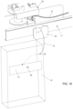
- FIG. 16 illustrates a fiber optic cable exiting the cable tray system to an equipment bay thereunder.
- the present invention comprises a large scale, automated physical cabling system for data centers to reduce the labor required to install and operate data centers and to eliminate errors associated with fiber optic cable bend radius management, labeling and documentation.
- the invention further enables the use of reduced diameter optical fiber cabling without bulky strength members and jacketing, which allows the density of fibers with a given cable tray volume to increase by a factor of ten. This translates directly to increased network bandwidth and compute capacity within a data center of a given size.
- the cables are installed along pre-calculated paths, such that excess cable lengths are distributed optimally along the cable tray system based on factors including the local volume of pre-existing cables within the cable trays.
- FIG. 1 A block diagram of this automated and computer controlled cable deployment system constructed in accordance with a preferred embodiment of the invention is illustrated in FIG. 1 .
- This system consists of one or more motorized, self-powered cable dispensing robots or shuttles 19 that dispense fiber optic cable that is pre-spooled on a cable cartridge 20 - 1 , by programmatically unspooling the cable from the cable cartridge and paying the cable out along a potentially transverse oscillatory path (e.g. sinusoidal curve) of fiber 12 as the robot 19 moves down a cable tray network comprised of a plurality of straight track segments 26 - 1 , 26 - 2 etc. and a plurality of switchable intersecting track segments 23 - 1 and 23 - 2 that are arranged adjacent and above large numbers of equipment bays 10 .
- a potentially transverse oscillatory path e.g. sinusoidal curve
- the cable-dispensing robot 19 is preferably powered by a battery 16 that is periodically charged by docking with a charging system 38 and communicates wirelessly via a wireless module 40 with a controller 36 .
- the controller 36 accesses a database 34 which stores the state of all cables within the cable tray network, including their start and stop locations, cable lengths and potentially manufacturing data (insertion loss, serial number, lot number, etc.).
- the database 34 further stores information regarding the availability of cable cartridges 20 of standard cable lengths, potentially stored within a cable cassette loading/unloading system, and raises an alert indicating the need to replenish certain pre-determined, standard cable lengths based on automatic inventory tracking.
- the controller 36 includes a user interface or programming interface that allows it to receive instructions on where and how to spatially deploy a fiber optic interconnect cable within the tray network of a data center facility.
- the system of interconnected, potentially oscillatory cable paths ( 12 , 14 ) resides above (or in some cases below) the equipment racks and the nominal location of cables follows a substantially rectilinear grid parallel to the array of network equipment cabinets 10 .
- the locations of the wireless transmitter 37 , controller 36 , charging stations 38 , and equipment bays 10 are shown by way of example in this figure.
- the fiber optic cable path 12 with first spatial period and path 14 with second spatial period follow an oscillatory pattern, wherein the spatial period of the oscillation is computed based on the excess cable length to be managed and the preexisting, locally varying density of cables along the tray system.
- the shortest path-length between two network device ports requiring a connection is equal to the nearest available length of fiber cable cartridge 20 that is greater than the shortest path length and that does not cause the local cable density in the tray to exceed the rated limits.
- FIG. 3 is a flow diagram of the algorithm used to compute the optimal physical path of each fiber interconnection within the fixed cable tray network.
- the goal of the algorithm is to distribute the excess cable length uniformly within the cable tray system to avoid clustering or bunching of cables at certain locations, which is a common concern when large numbers of cables are manually installed with all the slack bunched in the vicinity of one or both cable endpoints.
- the algorithm further tries to avoid local spots in the cable tray system for which the cable fill factor is approaching 100%.
- the first step in the routing process is to enter the start and stop locations of the cable as required to connect a pair of network devices at step 100 and determine the location of start and stop points on cable tray map at step 102 . This may be performed by an operator, engineer, or programmatically by reading in, for example, a spreadsheet with required connections and physical coordinates for each connection.
- the next step 104 is to compute the shortest possible cable length between the two endpoints by following straight-line paths along the rectilinear array of cable trays/tracks. This calculation includes the determination of the density of pre-existing cables within the tray system and the identification of any cable clusters that may be clogging or overfilling the tray system.
- the system checks the inventory of available cable cartridges in different lengths at step 108 and selects the shortest available cable length that is longer than the computed shortest possible cable length. The difference between the two lengths is what determines the period and potentially the amplitude of the oscillatory path.
- the cartridge can be loaded manually or automatically by cassette loader 41 .
- the oscillatory path y(x) is described by one or more sinusoidally varying segments characterized mathematically and physically by an amplitude of oscillation a and spatial period of oscillation b.
- the oscillatory path length is computed at step 110 , for example, with amplitude of 25 cm while the period of oscillation is decreased from 10 meters to 1 cm. This selection for amplitude translates into a cable tray with an inside width of at least 50 cm.
- the path length calculation in step 110 is typically iterative and based on numerical integration and differentiation of the cable path function y(x), as shown in FIG. 3 .
- the local period of oscillation is calculated by setting the corresponding path-length with oscillations equal to the cable length of the available cable cartridge.
- the next step is to load the selected cable cartridge into the dispensing robot, by manual or automatic means.
- the cable is then deployed in the cable tray system at step 112 , wherein the system lays out the cable according to the calculated oscillatory path.
- FIG. 4 A is an example graph of a sinusoidal oscillatory path segment with substantially constant 25 cm amplitude a and a variable spatial period b, the period being set to produce the desired path-length.
- the sinusoidal path versus a square wave is desirable because it subjects the fiber optic cable to minimal bending stress where it turns around.
- the optimal path is a slight variation of a sinusoid, in which the path consists of rectangular segments with substantially rounded corners, as shown in the dotted line in FIG. 4 A .
- the radius of rounded corners is selected based on the minimum acceptable bend radius for that particular fiber.
- the minimum acceptable radius (while maintaining low optical insertion loss and low bending stress in glass fiber) varies from >25 mm down to ⁇ 5 mm.
- FIGS. 4 B and 4 C illustrate a top view and a cross-sectional view, respectively, of multiple independent cables with different periods of oscillation, laid upon one another within a straight segment of the cable tray.
- FIG. 4 D illustrates an extended cable tray network 17 with localized high cable density 29 , medium cable density 30 , and low cable density 31 regions.
- the local period of oscillation of each cable laid therein varies based upon the local cable density.
- the distribution of pre-existing cable density is entered into the cable calculation process (step 110 ) of flow chart ( FIG. 3 ). For example, the cable segment 12 exhibits a short oscillation period within the low-density region 31 and the cable segment 14 exhibits a longer oscillation period within the medium cable density regions 30 to tend to even out the fill factor.
- the cable period of oscillation is very long or infinite (no oscillation), so that a minimal volume of cable is dispensed in this already full region 29 .
- it is preferred that subsequent cables laid therein are dispensed with a trajectory that reduces the variation in the cable tray fill factor along its length.
- FIG. 5 is a graph illustrating path length as a function of oscillation period of the oscillatory path for a fixed 25-cm oscillation amplitude a and with a programmable spatial period b varying from 10-cm to 100-cm for an individual installed fiber cable path within the cable tray.
- This path length calculation is based on a specific example: a 100-meter long cable tray with 25-cm transverse oscillation amplitude.
- the horizontal axis in FIG. 5 is the spatial period of oscillation in cm, and the vertical axis is the path-length in meters of the oscillatory path as a function of the spatial period. It can be seen that the amount of slack cable distributed along the 100-m length is significant.
- an oscillation period of 10-m maintains the path length at only slightly more than 100-m, the straight-line length of the cable tray segment.
- the path length increases to 150-m.
- the path length increases to nearly 500-m. Therefore, this oscillatory approach is very effective at managing and distributing slack cable within the cable tray system.
- FIG. 6 A illustrates a rectilinear cable tray/track system 17 installed above and parallel to aisles of the equipment bays 10 within a data center.
- one or more of the charging stations 38 are disposed to charge the robot battery (not shown) in between reconfigurations.
- the robot communication to the server 36 is via a wireless connection, so a wireless signal distribution antenna 37 with sufficient range is required in proximity to the track segments.
- cable tray systems 17 are typically elevated and run above the tops of the equipment racks 10 . Technicians must use ladders to access trays and run cables therein, which is a time consuming, labor-intensive process.
- Fiber optic cables within these trays takes several forms, including individual duplex or simplex cables with 0.9-mm, 1.6-mm, 2.0-mm or 3.0-mm outer diameters. Moreover, larger diameter structured cabling with outer diameters ranging from 3-mm to 10-mm and fiber counts of 12 to 96 per jacket may be used up to limits in diameter of fiber bundle that can be dispensed. Cable tray systems can be complex, including two tiers of cable trays at different heights, with each tray being utilized for a different type of cable (e.g. optical fiber vs. copper).
- the cable tray system 17 includes a bottom cable tray section 21 and further incorporates an upper track system 26 integral with a tray cover 18 to support and guide the cable dispensing robot 19 .
- the cable dispensing robot 19 accepts a standard patchcord cartridge 20 and then travels down the track system autonomously with the intelligence to optimally dispense/route cable to minimize clustering of the cables within the trays and to automatically manage excess cable lengths.
- Fiber optic cables with protective jackets and KEVLAR strength reinforcement are typically 1.6 to 3.0-mm in diameter. This structure is required to protect the internal optical fiber during manual installation into trays. This manual process involves pulling the cable, which would otherwise damage cables if they did not have protective jackets and KEVLAR strength reinforcement. The added size and mass of the cable is significant and limits the cable density within the cable tray.
- Bend insensitive optical fiber e.g. Corning CLEARCURVE ZBL, single mode and multimode
- the fiber diameter of a tight buffered or loose tube optical fiber is typically only 0.5 to 0.9-mm in diameter. This significantly increases the density achievable within the cable tray system by a factor of ten or more.
- deployable fiber cassettes in accordance with this invention would include two fibers that are deployed substantially parallel to one another. In the preferred embodiment, this miniature fiber 11 is spooled on the cable cartridges 20 in FIG. 7 and is ready for deployment.
- the small outer diameter facilitates spooling and deployment by the cabling robot 19 .
- the cable tray system as illustrated in FIG. 8 consists of multiple interlocking cable tray segments typically constructed of injection molded plastic or metal wire mesh tray segments with suitable hardware to suspend from a ceiling or mount to the top of the racks and/or enclosures.
- Cable trays include a bottom section 21 or trough for storage of cables and an upper section 18 forming a top cover. This top cover must have an integral track structure.
- Cable tray sections further include outlet ports 22 from which cables exit the tray and connect to equipment thereunder.
- the cable trays 17 built up of interlocking cable tray segments 26 may intersect at right angles, and at the switch segments 23 an actuator element 24 is provided to turn/redirect the cable dispensing robot 19 along a different substantially straight line path as required.
- FIG. 9 illustrates the cable tray system with two cables 12 - 1 and 12 - 3 disposed therein. Cables will typically cross over one another at intersection points in the switch segments 23 .
- FIG. 11 illustrates a reciprocating arm 25 of cable dispensing robot 19 suspended from track segment 26 , wherein the arm with feed rollers 27 is used to deploy the cable 11 from the spool 20 to the cable tray (not shown here for clarity) in the shape of the oscillatory path 12 with period b and amplitude a.
- the robot 19 further includes first and second drive motors 35 - 1 , 35 - 2 that transport the robot 19 down curved track section 33 , as shown in FIG. 15 . Power is supplied by internal battery 16 . Once the robot 19 reaches the destination point ( FIG.
- the reciprocating arm 25 moves to the outlet port 22 and feeds the remaining cable 12 and its connectorized end 32 off of the spool 20 , so that the cable's connector 32 drops out of cable tray port 22 and a drop down cable segment 13 of cable 12 has sufficient length to reach the corresponding port 42 of a network device 41 within the rack 10 below.
- FIGS. 12 - 14 detail the robot 19 as it travels through an intersection or crossing-point segment 23 , in which a switchable track segment 28 allows the dispensing robot 19 to change direction while deploying the cable.
- the cable can then be routed through a 90 or 180-degree angle through the switch section.
- the autonomous cabling system comprises the following elements:
- the robotic dispenser includes the following features in addition to those set forth above:
- the robotic cable dispenser 19 or shuttle carries one or more small diameter fiber optic cables pre-wound on a spool 20 .
- a technician selects and installs a pre-loaded spool with correct cable length into the dispenser at a starting point.
- the spool is configured to allow the dispenser to pay out cable by rotating the spool in coordination with its travel down the cable tray system 17 .
- Both ends of cable on spool may further include a unique label, barcode or RFID identifier in the vicinity of the connector that is automatically entered into the management system at the time of installation.
- the shuttle travels on guide tracks 26 laid out parallel and/or perpendicular to the aisles.
- the shuttle is controlled wirelessly and is battery powered.
- the fiber optic tray system 17 is arranged in a rectangular grid and the trays define the paths over which the cables may be routed. Routing is based on computation of the optimal path based on current fill state of cable tray system so that congestion of the cable tray at any particular location is avoided. Cabling system's software engine residing on management server 36 performs the routing calculation.
- the fiber optic connectors 32 at both ends of each cable 12 include an RFID reader and/or barcode.
- the shuttle includes an RFID reader and/or a camera scanning system to read the barcodes.
- the shuttle pays-out fiber from a spool cartridge 20 .
- the load produced by the fiber optic cable is relatively low and the suspended shuttle can be relatively small, compact and inexpensive.
- this interconnect architecture and system reduces the need for intermediate distribution frames and main distribution frames (IDFs and MDFs, respectively).
- IDFs and MDFs main distribution frames
- Programmable, direct fiber optic cable connections 12 , 14 can be made between all equipment bays. This allows for significant space and cost reduction.
- One robot or shuttle 19 can replace all the distribution frames and technicians normally deployed in the data center.
- the optimal path to route each cable 12 along the cable tray grid is selected by a network management controller, based on the three-dimensional locations of cable endpoints and on available lengths of the cable provided in spool form and loaded into the cable dispensing robot 19 .
- An algorithm is used by controller to automatically manage and distribute the slack cable within the cable track so that the cable installation is highly organized. For example, the spatial period and amplitude of repeated transverse oscillation pattern of cable is computed by the control system to uniformly distribute slack along the cable tray and reduce excessive bunching and overfilling at certain locations along the tray.
- the system for automated data center cabling installation thus includes the following key elements of the system:
- the cable-laying robot can also remove a specific cable from the cable tray by re-spooling it into the cable-laying robot.
- This cable can potentially be re-used.
- connectors may be removed and the cable may be cut into substantially straight sub-sections, with the cuts located at positions along the cable trays where the cable undergoes a change of direction, say by 90-degrees or 180-degrees. These cable sub-sections can then be removed by re-spooling it into the cable-laying robot.
- a segment of track network 17 may extend into a cable cassette loading/unloading system 41 , said loading/unloading system including actuation means to select and present a particular cassette 20 with length of cable 11 to the cable dispensing robot 19 so that further actuation installs a new cassette 20 into robot 19 .
- the loading/unloading system 41 may also include actuation means to remove spool of cassette 20 once the cable 11 is fully dispensed.
Landscapes
- Physics & Mathematics (AREA)
- Engineering & Computer Science (AREA)
- Architecture (AREA)
- Civil Engineering (AREA)
- Structural Engineering (AREA)
- General Physics & Mathematics (AREA)
- Optics & Photonics (AREA)
- Manipulator (AREA)
- Electric Cable Arrangement Between Relatively Moving Parts (AREA)
Abstract
Description
-
- 1. A network of fiber
optic cable trays 17 situated above theracks 10 of a data center; - 2. Cable tray covers 18 with integrated robotic
dispenser guidance track 26; - 3. Crossing sections with switchable
robot track segment 28; - 4. One or more
robotic cable dispensers 19 that move along track; - 5. Fiber cable routing algorithm to connect any two ports based on three-dimensional coordinates of ports being connected with an oscillatory path to accommodate slack cable length;
- 6. A further algorithm to enable multiple
robotic dispensers 19 to operate concurrently within the same cable tray network; - 7. Robotic dispensers including a reciprocating fiber payout means 25;
- 8. Robot track segments having radiused ingress and
egress ports 22 oriented normal to longitudinal axis of track to allow fiber optic cables to drop down out of trays so they can be routed down side of equipment rack and terminated on network equipment port; - 9.
Central management server 36 coordinating movement of one or morerobotic dispensers 19 and preventing collisions while optimizing paths taken; and - 10. Docking charge station(s) 38 distributed along cable tray system for charging of robotic dispenser.
- 1. A network of fiber
-
- 1. Pivoting, wheeled truck assemblies 39 with traction wheels and motorized propulsion means 35 for engagement onto track integral to cable tray;
- 2. RFID reader to read identity of cable;
- 3. Machine vision subsystem with built-in lighting;
- 4. Rechargeable battery to power dispenser; and
- 5.
Wireless communications module 40 to communicate withserver 36.
-
- 1. Overhead fiber
optic cable trays 17 with integral guidingtrack 26 on which self powered dispensing robot travels; - 2. Wheeled
cable dispensing robot 19 that lays small diameter simplex, duplex ormicro-distribution fiber 12 for maximum density within a cable tray; - 3. Cable laying robot is able to navigate right angle turns and/or switches 23;
- 4. Management system and algorithm residing on
server 36 that automatically computes cable path (e.g. 12, 14) in trays based on desired endpoints of cable, wherein software management and control system calculates transverse wiggle amplitude and period of cable. This accommodates slack of a given prepared and connectorized cable length while laying the cable between different racks as shown inFIG. 6 .
- 1. Overhead fiber
Claims (21)
Applications Claiming Priority (1)
| Application Number | Priority Date | Filing Date | Title |
|---|---|---|---|
| PCT/US2017/069160 WO2019133021A1 (en) | 2017-12-30 | 2017-12-30 | Automated installation and reconfiguration of fiber optic and copper cables in large scale data centers |
Publications (2)
| Publication Number | Publication Date |
|---|---|
| US20200358277A1 US20200358277A1 (en) | 2020-11-12 |
| US11705707B2 true US11705707B2 (en) | 2023-07-18 |
Family
ID=67068034
Family Applications (1)
| Application Number | Title | Priority Date | Filing Date |
|---|---|---|---|
| US16/958,704 Active 2038-07-07 US11705707B2 (en) | 2017-12-30 | 2017-12-30 | Automated installation and reconfiguration of fiber optic and copper cables in large scale data centers |
Country Status (3)
| Country | Link |
|---|---|
| US (1) | US11705707B2 (en) |
| EP (1) | EP3732520B1 (en) |
| WO (1) | WO2019133021A1 (en) |
Families Citing this family (14)
| Publication number | Priority date | Publication date | Assignee | Title |
|---|---|---|---|---|
| US11252488B2 (en) | 2017-10-09 | 2022-02-15 | Telescent Inc. | Incrementally scalable, two-tier system of robotic, fiber optic interconnect units enabling any-to-any connectivity |
| WO2018071341A2 (en) | 2016-10-10 | 2018-04-19 | Telescent Inc. | System of large scale robotic fiber cross-connects using multi-fiber trunk reservation |
| WO2019068052A1 (en) | 2017-09-30 | 2019-04-04 | Telescent Inc. | Low loss optical monitors, optical monitor arrays and optical monitor patch-panels |
| EP3732520B1 (en) | 2017-12-30 | 2024-01-24 | Telescent Inc. | Automated installation and reconfiguration of fiber optic and copper cables in large scale data centers |
| US11650598B2 (en) | 2017-12-30 | 2023-05-16 | Telescent Inc. | Automated physical network management system utilizing high resolution RFID, optical scans and mobile robotic actuator |
| US11327264B2 (en) | 2019-09-05 | 2022-05-10 | Telescent Inc. | Fiber optic tensioning reel sub-system in robotic fiber optic cross-connect systems, sub-systems, devices and methods |
| US11866079B2 (en) * | 2020-02-14 | 2024-01-09 | Georgia Tech Research Corporation | Wire-traversing robot and method of operation |
| US11347955B2 (en) | 2020-03-09 | 2022-05-31 | Panduit Corp. | Cable management system and method |
| CN111716351A (en) * | 2020-05-08 | 2020-09-29 | 南方电网科学研究院有限责任公司 | Control system of wire construction robot |
| CN113945178B (en) * | 2020-07-15 | 2023-10-20 | 中国电信股份有限公司 | Computer room fiber jumping length calculation method and system |
| CN113595565B (en) * | 2021-07-29 | 2022-11-29 | 四川省大见通信技术有限公司 | Micro-distribution equipment supporting remote frequency conversion |
| DE102021132837A1 (en) | 2021-12-13 | 2023-06-15 | Goodville Gmbh | Cable laying system for the automated laying of cables in a building with a cable laying device and cable laying device |
| US20230298488A1 (en) * | 2022-03-18 | 2023-09-21 | CyberSecure IPS, LLC | Facilitating installation of cables within datacenters |
| US20240126040A1 (en) * | 2022-10-13 | 2024-04-18 | Corning Research & Development Corporation | Routing tool for installation of fiber optic cables and method of using same |
Citations (38)
| Publication number | Priority date | Publication date | Assignee | Title |
|---|---|---|---|---|
| FR2650922A1 (en) | 1989-08-08 | 1991-02-15 | Pecot Alain | Intermediate cable drivers with automatic control |
| FR2653946A1 (en) * | 1989-10-31 | 1991-05-03 | Dehe Entreprises A | Method for unreeling and installing a fibre-optic cable and installation for the implementation of this method |
| US5551545A (en) * | 1994-03-18 | 1996-09-03 | Gelfman; Stanley | Automatic deployment and retrieval tethering system |
| US6584267B1 (en) | 2000-06-02 | 2003-06-24 | Panduit Corp. | Cable management system |
| US6603907B2 (en) | 2001-03-16 | 2003-08-05 | Neutron Media, Llc | Communications network and method of installing the same |
| US7289197B2 (en) | 2004-12-22 | 2007-10-30 | Anthony Stephen Kewitsch | Transmissive optical detector |
| US7315681B2 (en) | 2004-08-09 | 2008-01-01 | Anthony Kewitsch | Fiber optic rotary coupling and devices |
| US7331436B1 (en) * | 2003-03-26 | 2008-02-19 | Irobot Corporation | Communications spooler for a mobile robot |
| US7460753B2 (en) | 2006-07-06 | 2008-12-02 | Anthony Stephen Kewitsch | Shape-retaining fiber optic cables having limited bend radius |
| US20090003761A1 (en) * | 2004-09-29 | 2009-01-01 | Yasunobu Matsuoka | Optoelectronic Integrated Circuit Device and Communications Equipment Using Same |
| US20090097797A1 (en) * | 2007-10-15 | 2009-04-16 | Anthony Stephen Kewitsch | Methods to reconfigure all-fiber optical cross-connects |
| US7665901B2 (en) | 2006-02-17 | 2010-02-23 | Telescent Inc. | Protective fiber optic union adapters |
| US20100278500A1 (en) | 2009-04-30 | 2010-11-04 | Campos Cesar Alejandro De Los Santos | Mounting Assembly for Fiber Optic Equipment |
| US20100329621A1 (en) * | 2009-06-26 | 2010-12-30 | Elli Makrides-Saravanos | Fiber Optic Cable Slack Storage Module |
| US7920764B2 (en) | 2007-05-04 | 2011-04-05 | Anthony Stephen Kewitsch | Electrically traceable and identifiable fiber optic cables and connectors |
| AU2010262903A1 (en) * | 2009-06-19 | 2012-02-02 | Corning Cable Systems Llc | High capacity fiber optic connection infrastructure apparatus |
| US20130064506A1 (en) * | 2011-09-12 | 2013-03-14 | Tyco Electronics Corporation | Flexible lensed optical interconnect device for signal distribution |
| US8488938B2 (en) | 2008-08-21 | 2013-07-16 | Telescent Inc. | Braided fiber optic cross-connect switches |
| US8554033B2 (en) | 2008-05-02 | 2013-10-08 | Telescent Inc. | Radio frequency identification overlay network for fiber optic communication systems |
| CN103427371A (en) * | 2013-08-16 | 2013-12-04 | 中冶南方工程技术有限公司 | Intelligent cable path optimizing method |
| CN203786352U (en) * | 2014-01-27 | 2014-08-20 | 西安海驰通信科技有限公司 | LC type small diameter optical fiber patch cord |
| KR20140133286A (en) * | 2013-05-10 | 2014-11-19 | 주식회사 로보게이트 | Robot for Cable Tray |
| KR20150030043A (en) | 2013-09-11 | 2015-03-19 | 삼성중공업 주식회사 | System for cable feeding |
| KR20150087043A (en) * | 2014-01-21 | 2015-07-29 | 대우조선해양 주식회사 | Apparatus for cable twist detecting and method thereof |
| US9110249B2 (en) | 2007-10-02 | 2015-08-18 | Telescent Inc. | In-line fiber optic monitors responsive to optical intensity |
| US20150331200A1 (en) * | 2012-12-20 | 2015-11-19 | Wave2Wave Solution Inc. | Switching patch cord fibers |
| US20160107312A1 (en) * | 2014-10-21 | 2016-04-21 | Centurylink Intellectual Property Llc | Automated Data Center |
| US20160140259A1 (en) * | 2014-11-13 | 2016-05-19 | Lenovo Enterprise Solutions (Singapore) Pte. Ltd. | Optimized placement design of network and infrastructure components |
| WO2016099831A1 (en) * | 2014-12-14 | 2016-06-23 | Telescent Inc. | High reliability robotic cross-connect systems |
| US20170193134A1 (en) * | 2015-12-31 | 2017-07-06 | Beijing Institute Of Technology | Method and device for automatically routing multi-branch cable |
| US9703060B2 (en) | 2013-10-04 | 2017-07-11 | Telescent Inc. | Ultra-compact, software-defined fiber optic patch-panels |
| US20190293875A1 (en) | 2016-10-10 | 2019-09-26 | Telescent Inc. | System of large scale robotic fiber cross-connects using multi-fiber trunk reservation |
| US20200003978A1 (en) | 2017-09-30 | 2020-01-02 | Telescent Inc. | Low Loss Optical Monitors, Optical Monitor Arrays and Optical Monitor Patch-panels |
| US20200041725A1 (en) | 2016-10-10 | 2020-02-06 | Telescent Inc. | Ultra-Scalable, Multi-Tiered, Robotic Fiber Optic Cross-Connect Utilizing Trunk Line Physical Aggregation |
| US20200358277A1 (en) | 2017-12-30 | 2020-11-12 | Telescent Inc. | Automated installation and reconfiguration of fiber optic and copper cables in large scale data centers |
| US20200359117A1 (en) | 2017-10-09 | 2020-11-12 | Telescent, Inc. | Incrementally scalable, two-tier system of robotic, fiber optic interconnect units enabling any-to-any connectivity |
| US20210072483A1 (en) | 2019-09-05 | 2021-03-11 | Telescent Inc. | Fiber Optic Tensioning Reel Sub-System In Robotic Fiber Optic Cross-Connect Systems, Sub-Systems, Devices And Methods |
| US10977458B2 (en) | 2017-12-30 | 2021-04-13 | Telescent Inc. | Automated physical network management system utilizing high resolution RFID and optical scanning for RFID tag spatial localization |
-
2017
- 2017-12-30 EP EP17936770.1A patent/EP3732520B1/en active Active
- 2017-12-30 US US16/958,704 patent/US11705707B2/en active Active
- 2017-12-30 WO PCT/US2017/069160 patent/WO2019133021A1/en unknown
Patent Citations (54)
| Publication number | Priority date | Publication date | Assignee | Title |
|---|---|---|---|---|
| FR2650922A1 (en) | 1989-08-08 | 1991-02-15 | Pecot Alain | Intermediate cable drivers with automatic control |
| FR2653946A1 (en) * | 1989-10-31 | 1991-05-03 | Dehe Entreprises A | Method for unreeling and installing a fibre-optic cable and installation for the implementation of this method |
| US5551545A (en) * | 1994-03-18 | 1996-09-03 | Gelfman; Stanley | Automatic deployment and retrieval tethering system |
| US6584267B1 (en) | 2000-06-02 | 2003-06-24 | Panduit Corp. | Cable management system |
| US6603907B2 (en) | 2001-03-16 | 2003-08-05 | Neutron Media, Llc | Communications network and method of installing the same |
| US7331436B1 (en) * | 2003-03-26 | 2008-02-19 | Irobot Corporation | Communications spooler for a mobile robot |
| US7315681B2 (en) | 2004-08-09 | 2008-01-01 | Anthony Kewitsch | Fiber optic rotary coupling and devices |
| US20090003761A1 (en) * | 2004-09-29 | 2009-01-01 | Yasunobu Matsuoka | Optoelectronic Integrated Circuit Device and Communications Equipment Using Same |
| US7289197B2 (en) | 2004-12-22 | 2007-10-30 | Anthony Stephen Kewitsch | Transmissive optical detector |
| US7665901B2 (en) | 2006-02-17 | 2010-02-23 | Telescent Inc. | Protective fiber optic union adapters |
| US8480310B2 (en) | 2006-02-17 | 2013-07-09 | Telescent Inc. | Protective fiber optic union adapters |
| US7460753B2 (en) | 2006-07-06 | 2008-12-02 | Anthony Stephen Kewitsch | Shape-retaining fiber optic cables having limited bend radius |
| US8150227B2 (en) | 2007-05-04 | 2012-04-03 | Telescent Inc. | Electrically traceable and identifiable fiber optic cables and connectors |
| US7920764B2 (en) | 2007-05-04 | 2011-04-05 | Anthony Stephen Kewitsch | Electrically traceable and identifiable fiber optic cables and connectors |
| US8428405B2 (en) | 2007-05-04 | 2013-04-23 | Telescent Inc. | Electrically traceable and identifiable fiber optic cables and connectors |
| US9110249B2 (en) | 2007-10-02 | 2015-08-18 | Telescent Inc. | In-line fiber optic monitors responsive to optical intensity |
| US10895691B2 (en) | 2007-10-15 | 2021-01-19 | Telescent Inc. | Scalable and modular automated fiber optic cross-connect systems |
| US10042122B2 (en) | 2007-10-15 | 2018-08-07 | Telescent Inc. | Scalable and modular automated fiber optic cross-connect systems |
| US9052465B2 (en) | 2007-10-15 | 2015-06-09 | Telescent Inc. | Methods to reconfigure all-fiber optical cross-connects |
| US8068715B2 (en) * | 2007-10-15 | 2011-11-29 | Telescent Inc. | Scalable and modular automated fiber optic cross-connect systems |
| US8463091B2 (en) | 2007-10-15 | 2013-06-11 | Telescent Inc. | Methods to reconfigure all-fiber optical cross-connects |
| US9411108B2 (en) | 2007-10-15 | 2016-08-09 | Telescent Inc. | Scalable and modular automated fiber optic cross-connect systems |
| US20090097797A1 (en) * | 2007-10-15 | 2009-04-16 | Anthony Stephen Kewitsch | Methods to reconfigure all-fiber optical cross-connects |
| US8805155B2 (en) | 2007-10-15 | 2014-08-12 | Telescent Inc. | Scalable and modular automated fiber optic cross-connect systems |
| US8554033B2 (en) | 2008-05-02 | 2013-10-08 | Telescent Inc. | Radio frequency identification overlay network for fiber optic communication systems |
| US8488938B2 (en) | 2008-08-21 | 2013-07-16 | Telescent Inc. | Braided fiber optic cross-connect switches |
| US9052490B2 (en) | 2008-08-21 | 2015-06-09 | Telescent Inc. | Braided fiber optic cross-connect switches |
| US9188748B2 (en) | 2008-12-03 | 2015-11-17 | Telescent Inc. | Radio frequency identification overlay network for fiber optic communication systems |
| US20100278500A1 (en) | 2009-04-30 | 2010-11-04 | Campos Cesar Alejandro De Los Santos | Mounting Assembly for Fiber Optic Equipment |
| AU2010262903A1 (en) * | 2009-06-19 | 2012-02-02 | Corning Cable Systems Llc | High capacity fiber optic connection infrastructure apparatus |
| US20100329621A1 (en) * | 2009-06-26 | 2010-12-30 | Elli Makrides-Saravanos | Fiber Optic Cable Slack Storage Module |
| US20130064506A1 (en) * | 2011-09-12 | 2013-03-14 | Tyco Electronics Corporation | Flexible lensed optical interconnect device for signal distribution |
| US9575258B2 (en) * | 2012-12-20 | 2017-02-21 | Wave2Wave Solution Inc. | Switching patch cord fibers |
| US20150331200A1 (en) * | 2012-12-20 | 2015-11-19 | Wave2Wave Solution Inc. | Switching patch cord fibers |
| KR20140133286A (en) * | 2013-05-10 | 2014-11-19 | 주식회사 로보게이트 | Robot for Cable Tray |
| CN103427371A (en) * | 2013-08-16 | 2013-12-04 | 中冶南方工程技术有限公司 | Intelligent cable path optimizing method |
| KR20150030043A (en) | 2013-09-11 | 2015-03-19 | 삼성중공업 주식회사 | System for cable feeding |
| US9703060B2 (en) | 2013-10-04 | 2017-07-11 | Telescent Inc. | Ultra-compact, software-defined fiber optic patch-panels |
| KR20150087043A (en) * | 2014-01-21 | 2015-07-29 | 대우조선해양 주식회사 | Apparatus for cable twist detecting and method thereof |
| CN203786352U (en) * | 2014-01-27 | 2014-08-20 | 西安海驰通信科技有限公司 | LC type small diameter optical fiber patch cord |
| US20160107312A1 (en) * | 2014-10-21 | 2016-04-21 | Centurylink Intellectual Property Llc | Automated Data Center |
| US20160140259A1 (en) * | 2014-11-13 | 2016-05-19 | Lenovo Enterprise Solutions (Singapore) Pte. Ltd. | Optimized placement design of network and infrastructure components |
| US20160202424A1 (en) * | 2014-12-14 | 2016-07-14 | Telescent Inc. | High reliability robotic cross-connect systems |
| US10345526B2 (en) | 2014-12-14 | 2019-07-09 | Telescent Inc. | High reliability robotic cross-connect systems |
| US10649149B2 (en) | 2014-12-14 | 2020-05-12 | Telescent Inc. | High reliability robotic cross-connect systems |
| WO2016099831A1 (en) * | 2014-12-14 | 2016-06-23 | Telescent Inc. | High reliability robotic cross-connect systems |
| US20170193134A1 (en) * | 2015-12-31 | 2017-07-06 | Beijing Institute Of Technology | Method and device for automatically routing multi-branch cable |
| US20190293875A1 (en) | 2016-10-10 | 2019-09-26 | Telescent Inc. | System of large scale robotic fiber cross-connects using multi-fiber trunk reservation |
| US20200041725A1 (en) | 2016-10-10 | 2020-02-06 | Telescent Inc. | Ultra-Scalable, Multi-Tiered, Robotic Fiber Optic Cross-Connect Utilizing Trunk Line Physical Aggregation |
| US20200003978A1 (en) | 2017-09-30 | 2020-01-02 | Telescent Inc. | Low Loss Optical Monitors, Optical Monitor Arrays and Optical Monitor Patch-panels |
| US20200359117A1 (en) | 2017-10-09 | 2020-11-12 | Telescent, Inc. | Incrementally scalable, two-tier system of robotic, fiber optic interconnect units enabling any-to-any connectivity |
| US20200358277A1 (en) | 2017-12-30 | 2020-11-12 | Telescent Inc. | Automated installation and reconfiguration of fiber optic and copper cables in large scale data centers |
| US10977458B2 (en) | 2017-12-30 | 2021-04-13 | Telescent Inc. | Automated physical network management system utilizing high resolution RFID and optical scanning for RFID tag spatial localization |
| US20210072483A1 (en) | 2019-09-05 | 2021-03-11 | Telescent Inc. | Fiber Optic Tensioning Reel Sub-System In Robotic Fiber Optic Cross-Connect Systems, Sub-Systems, Devices And Methods |
Non-Patent Citations (7)
| Title |
|---|
| EPO, Provisional Opinion Accompanying the Partial Search Result for European Application No. EP17936770 (dated Aug. 12, 2021) pp. 1-5. |
| EPO, Supplementary Partial European Search Report for European Application No. EP17936770 (dated Aug. 12, 2021) pp. 1-5. |
| FibreFab Fibre Optic Cable Catalogue, ver7.11, 2011 (Year: 2011). * |
| Legrand PW cable tray systems catalog Jun. 23, 2016, https://catalogos-web.s3.amazonaws.com/PW-2017-2018.pdf (Year: 2016). * |
| PCT, International Preliminary Report on Patentability for International Application No. PCT/US2017/069160 (dated Jun. 30, 2020). |
| PCT, International Search Report for International Application No. PCT/US2017/069160 (dated Mar. 29, 2018). |
| PCT, Written Opinion of the International Searching Authority for International Application No. PCT/US2017/069160 (dated Mar. 29, 2018). |
Also Published As
| Publication number | Publication date |
|---|---|
| US20200358277A1 (en) | 2020-11-12 |
| EP3732520B1 (en) | 2024-01-24 |
| EP3732520A1 (en) | 2020-11-04 |
| EP3732520A4 (en) | 2021-12-29 |
| WO2019133021A1 (en) | 2019-07-04 |
Similar Documents
| Publication | Publication Date | Title |
|---|---|---|
| US11705707B2 (en) | Automated installation and reconfiguration of fiber optic and copper cables in large scale data centers | |
| RU2670183C2 (en) | Distribution device with incrementally added splitters | |
| KR100399659B1 (en) | Fiber distribution system | |
| US4948220A (en) | Module for distributing and connecting optical fibers | |
| CA1250135A (en) | Method and apparatus for handling and storing cabled spliced ends of fiber optics | |
| US6721482B1 (en) | Telecommunications fiber optic infrastructure | |
| EP2033033B1 (en) | A cable loop device for optical systems | |
| US8953920B2 (en) | Semi-automated optical fiber distribution system | |
| CN110456471B (en) | Telecommunications tray with cable routing pathways extending through pivoting hinges | |
| US20190072736A1 (en) | High density distribution frame with an integrated splicing compartment | |
| CN102844690A (en) | High density optical fiber distribution system | |
| KR101201989B1 (en) | Optical fibre coupling device and method | |
| TWI488395B (en) | Lateral storage spool for overhead cable pathway | |
| WO2002021186A1 (en) | High density fiber optic cable distribution frame system | |
| EP3230780B1 (en) | Fiber optic cable slack management module | |
| CN102089692A (en) | Optical fibre distribution module with storage reels and organiser | |
| US6487356B1 (en) | Fiber optic cable segregation and slack storage apparatus and method | |
| CN114026476A (en) | Pre-patch cable assembly for indoor/outdoor/data center applications | |
| US20190250351A1 (en) | Optical fiber rack | |
| US10481358B2 (en) | Termination unit | |
| WO2010001155A2 (en) | Improvements in or relating to optical fibre distribution systems | |
| US20230189468A1 (en) | Managing cables in fiber installation | |
| US9904028B2 (en) | Ultra-high density splice systems | |
| WO2002021181A1 (en) | Fiber optic cable bend radius management system | |
| US7200315B2 (en) | Dynamic fiber slack management for telecom racks |
Legal Events
| Date | Code | Title | Description |
|---|---|---|---|
| FEPP | Fee payment procedure |
Free format text: ENTITY STATUS SET TO UNDISCOUNTED (ORIGINAL EVENT CODE: BIG.); ENTITY STATUS OF PATENT OWNER: SMALL ENTITY |
|
| FEPP | Fee payment procedure |
Free format text: ENTITY STATUS SET TO SMALL (ORIGINAL EVENT CODE: SMAL); ENTITY STATUS OF PATENT OWNER: SMALL ENTITY |
|
| STPP | Information on status: patent application and granting procedure in general |
Free format text: DOCKETED NEW CASE - READY FOR EXAMINATION |
|
| AS | Assignment |
Owner name: TELESCENT INC., CALIFORNIA Free format text: ASSIGNMENT OF ASSIGNORS INTEREST;ASSIGNOR:KEWITSCH, ANTHONY STEPHEN;REEL/FRAME:057749/0705 Effective date: 20211009 Owner name: TELESCENT INC., CALIFORNIA Free format text: ASSIGNMENT OF ASSIGNORS INTEREST;ASSIGNOR:KEWITSCH, ANTHONY STEPHEN;REEL/FRAME:057749/0667 Effective date: 20211009 |
|
| STPP | Information on status: patent application and granting procedure in general |
Free format text: NON FINAL ACTION MAILED |
|
| STPP | Information on status: patent application and granting procedure in general |
Free format text: RESPONSE TO NON-FINAL OFFICE ACTION ENTERED AND FORWARDED TO EXAMINER |
|
| STPP | Information on status: patent application and granting procedure in general |
Free format text: FINAL REJECTION MAILED |
|
| STCF | Information on status: patent grant |
Free format text: PATENTED CASE |
|
| STCF | Information on status: patent grant |
Free format text: PATENTED CASE |