US11684182B2 - Weekender style floor display - Google Patents
Weekender style floor display Download PDFInfo
- Publication number
- US11684182B2 US11684182B2 US16/933,487 US202016933487A US11684182B2 US 11684182 B2 US11684182 B2 US 11684182B2 US 202016933487 A US202016933487 A US 202016933487A US 11684182 B2 US11684182 B2 US 11684182B2
- Authority
- US
- United States
- Prior art keywords
- panel
- display
- shelf
- fold line
- configuration
- Prior art date
- Legal status (The legal status is an assumption and is not a legal conclusion. Google has not performed a legal analysis and makes no representation as to the accuracy of the status listed.)
- Active
Links
- 230000000712 assembly Effects 0.000 claims description 19
- 238000000429 assembly Methods 0.000 claims description 19
- 239000000463 material Substances 0.000 claims description 15
- 238000000034 method Methods 0.000 abstract description 16
- 238000003197 gene knockdown Methods 0.000 description 29
- 239000003292 glue Substances 0.000 description 3
- 239000011087 paperboard Substances 0.000 description 3
- 239000000853 adhesive Substances 0.000 description 2
- 230000001070 adhesive effect Effects 0.000 description 2
- 230000009286 beneficial effect Effects 0.000 description 2
- 230000002093 peripheral effect Effects 0.000 description 2
- 238000003860 storage Methods 0.000 description 2
- 238000004026 adhesive bonding Methods 0.000 description 1
- 238000005452 bending Methods 0.000 description 1
- 230000003247 decreasing effect Effects 0.000 description 1
- 239000011094 fiberboard Substances 0.000 description 1
- 238000005304 joining Methods 0.000 description 1
- 238000004519 manufacturing process Methods 0.000 description 1
- 230000013011 mating Effects 0.000 description 1
- 238000012856 packing Methods 0.000 description 1
- 230000001932 seasonal effect Effects 0.000 description 1
- 235000011888 snacks Nutrition 0.000 description 1
- 239000011800 void material Substances 0.000 description 1
Images


Classifications
-
- A—HUMAN NECESSITIES
- A47—FURNITURE; DOMESTIC ARTICLES OR APPLIANCES; COFFEE MILLS; SPICE MILLS; SUCTION CLEANERS IN GENERAL
- A47F—SPECIAL FURNITURE, FITTINGS, OR ACCESSORIES FOR SHOPS, STOREHOUSES, BARS, RESTAURANTS OR THE LIKE; PAYING COUNTERS
- A47F5/00—Show stands, hangers, or shelves characterised by their constructional features
- A47F5/10—Adjustable or foldable or dismountable display stands
- A47F5/11—Adjustable or foldable or dismountable display stands made of cardboard, paper or the like
- A47F5/112—Adjustable or foldable or dismountable display stands made of cardboard, paper or the like hand-folded from sheet material
- A47F5/114—Adjustable or foldable or dismountable display stands made of cardboard, paper or the like hand-folded from sheet material in the form of trays with a base
-
- A—HUMAN NECESSITIES
- A47—FURNITURE; DOMESTIC ARTICLES OR APPLIANCES; COFFEE MILLS; SPICE MILLS; SUCTION CLEANERS IN GENERAL
- A47F—SPECIAL FURNITURE, FITTINGS, OR ACCESSORIES FOR SHOPS, STOREHOUSES, BARS, RESTAURANTS OR THE LIKE; PAYING COUNTERS
- A47F5/00—Show stands, hangers, or shelves characterised by their constructional features
- A47F5/10—Adjustable or foldable or dismountable display stands
- A47F5/11—Adjustable or foldable or dismountable display stands made of cardboard, paper or the like
- A47F5/112—Adjustable or foldable or dismountable display stands made of cardboard, paper or the like hand-folded from sheet material
- A47F5/116—Shelving racks
-
- A—HUMAN NECESSITIES
- A47—FURNITURE; DOMESTIC ARTICLES OR APPLIANCES; COFFEE MILLS; SPICE MILLS; SUCTION CLEANERS IN GENERAL
- A47F—SPECIAL FURNITURE, FITTINGS, OR ACCESSORIES FOR SHOPS, STOREHOUSES, BARS, RESTAURANTS OR THE LIKE; PAYING COUNTERS
- A47F5/00—Show stands, hangers, or shelves characterised by their constructional features
- A47F5/16—Platform-type show stands with flat, inclined, or curved upper surface
-
- A—HUMAN NECESSITIES
- A47—FURNITURE; DOMESTIC ARTICLES OR APPLIANCES; COFFEE MILLS; SPICE MILLS; SUCTION CLEANERS IN GENERAL
- A47B—TABLES; DESKS; OFFICE FURNITURE; CABINETS; DRAWERS; GENERAL DETAILS OF FURNITURE
- A47B43/00—Cabinets, racks or shelf units, characterised by features enabling folding of the cabinet or the like
- A47B43/02—Cabinets, racks or shelf units, characterised by features enabling folding of the cabinet or the like made of cardboard or the like
Definitions
- the present invention relates generally to point of purchase merchandise displays. More specifically, the present invention is concerned with a corrugated, paperboard display that is manufactured in a fold and/or glue assembly process and that is traditionally provided to an end user in a collapsed or knockdown configuration for setup.
- Corrugated displays and containers are often made from pieces of flat paperboard stock material that are die cut into shapes that define various panels.
- the shapes are folded along predefined lines between the panels, often with at least one overlapping strip or panel that is glued, taped or otherwise affixed to another panel to form an enclosed boundary.
- the panels are folded and/or glued into place to become the walls of the display or container.
- the displays or containers are traditionally provided to product manufacturers and/or retailers in a collapsed or knockdown configuration for storage, handling and shipping. The manufacturer and/or retailers open the knockdown containers and fold appropriately to utilize the assembled display or container for display and/or packing products therein.
- the knockdown displays or containers are typically manufactured by feeding flat die cut sheets through a fold-and-glue machine.
- the fold-and-glue machine applies adhesive and folds over select panels so that the panels are in the knockdown configuration.
- One common knockdown display is a weekender style display.
- a corrugated weekender display is typically used to display products to consumers at a point-of-sale location. In some instances, several weekender displays are utilized at a single location, often requiring significant resources to purchase, erect, locate, and load the same.
- weekender displays are specialized displays, such as displays that are designed for a specific limited-time promotion, such as for a seasonal promotion, a product promotion (such as on a release date, during a sale, or other times during which demand is higher than normal), a product clearance event (or other circumstance during which temporary display options are desired), and/or the like. Consequently, it is desirable to minimize the time and effort necessary to manufacture the weekender display and/or to erect the display from its knockdown configuration.
- weekender displays provide support on only the front and back of the shelf.
- weekender displays have relatively weak shelves that cannot support much weight, thereby limiting the versatility and/or decreasing their useful life.
- the weekender display has two opposed shelving scenes that share a rear panel and two side panels.
- “rear” means behind each shelf but within the central plane bisecting the display and each side panel.
- the opposed shelves are back-to-back or coplanar. In another embodiment, the opposed shelves are off-set or alternating.
- the weekender display is in a single-piece knock-down configuration.
- FIG. 1 is a plan view of a weekender style display according to embodiments of the present invention, the display shown in a knockdown configuration.
- FIG. 2 is a perspective view of the weekender style display of FIG. 1 , the display shown in an erected configuration.
- FIG. 5 is a partial perspective view showing an intermediate stage of moving a shelf assembly from a stowed configuration to a deployed configuration, the shelf assembly shown just after rotating support panels relative to side panels.
- FIG. 8 is a plan view of a weekender style display according to other embodiments of the present invention.
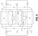
- FIG. 9 is a plan view of a weekender style display according to still other embodiments of the present invention.
- FIG. 10 is a perspective view of a weekender style display according to yet other embodiments of the present invention, the display shown in an erected configuration.
- FIG. 11 is a plan view of the weekender style display of FIG. 10 shown in a knockdown configuration.
- FIG. 12 is a perspective view of a weekender style display according to other embodiments of the present invention, the display shown in an erected configuration.
- FIG. 13 is a perspective view of the weekender style display of FIG. 12 , shown from a different angle.
- FIG. 14 is a plan view of the weekender style display of FIG. 12 , shown in a knockdown configuration.
- the present invention comprises a display having a base and a plurality of shelf assemblies, each formed from a single piece of material.
- the base includes a plurality of panels separated by respective fold lines so as to facilitate moving the display from a knockdown configuration to an erected configuration.
- Each shelf assembly includes a shelf member flanked by opposed side support panels, the shelf assembly being moved between a stowed configuration and a deployed configuration as the display is moved between the knockdown configuration and the erected configuration, respectively.
- the display is moveable to one or more flat configurations, such as by folding and gluing one or more panel together such that the display maintains a relatively low profile to facilitate shipping and storage while being readily moveable to an erected configuration.
- embodiments of the present invention include a weekender style display 10 having a base 100 and a plurality of shelf assemblies 200 for accommodating and displaying products such as, for instance, bagged snacks, pouches, or the like.
- the display 10 is formed from corrugated material, such as paperboard.
- other embodiments provide for the corrugated material to include other similar type materials, such as cardboard, fiberboard, or the like.
- the display is operable to be provided in a knockdown configuration (i.e., a generally flat, two-dimensional form), such as illustrated in FIGS. 1 , 8 , 9 , 11 , and 14 . From the knockdown configuration, the display is operable to be transformed into an erected configuration, such as shown in FIGS. 2 , 10 , 12 , and 13 .
- the first 130 a and second 130 b rear panels define a plurality of support apertures 150 sized and shaped to engage with respective shelve assemblies 200 of the display 10 , such as by receiving respective tab members 255 of respective shelf assemblies 200 .
- each side panel 120 a , 120 b is segmented into respective front 121 a , 121 b and rear 122 a , 122 b portions, thereby facilitating folding of the same onto each other.
- the display comprises a plurality of bottom panels 140 , each bottom panel extending from a bottom edge of a respective rear panel, side panel, front panel, or the like.
- each side panel is hingedly coupled to each shelf assembly 200 at a line of weakness 225 (each a “support hinge” 225 ), such as, e.g., an 8-point roundtop rule foldable crease, each support hinge 225 extending from the fold line 124 a and/or 124 b separating the side panel from the front panel to a lateral mid-point 240 a/b in the middle of the side panel.
- a line of weakness 225 each support hinge 225 extending from the fold line 124 a and/or 124 b separating the side panel from the front panel to a lateral mid-point 240 a/b in the middle of the side panel.
- the support hinge 225 does not extend into the rear portion 122 a , 122 b of the respective side panel.
- the support hinge 225 shown extends 45 degrees from horizontal when the display is erected.
- the plurality of panels defines a plurality of shelf assemblies 200 , each shelf assembly 200 having a shelf member 210 extending between opposed front and rear edges.
- the front edge of each shelf member is hingedly coupled to the front panel (the “front hinge” 212 ), thereby facilitating movement of each shelf member 210 between a stowed position and a deployed position, each such position being associated with a respective stowed and deployed configuration of the shelf assembly.
- the stowed and deployed configurations of the shelf assemblies are associated with a flat configuration and the erected configuration of the display, respectively.
- Each shelf member defines opposed left and right side edges, each such side edge being hingedly coupled to a respective left and right side support panel 220 .
- each support panel 220 is defined by an area positioned between a cut line (such as the S-shaped cuts shown), a support hinge 225 , and a longitudinal fold line (a “side hinge” 215 ) separating the shelf member 210 from the support panel 220 .
- the side hinge 215 is colinear with a longitudinal fold line 124 a and/or 124 b that separates the front panel 110 from a respective side panel when the display is in the knockdown configuration.
- the method includes folding each side panel in half such that an inner surface of the front panel is folded against an inner surface of the rear panel.
- the back panel 130 is a continuous panel and subpanels 130 a and 130 b merely refer to each half of the back panel 130 .
- each rear panel is folded along the longitudinal fold line 132 a and 132 b approximately 90 degrees with respect to its adjacent side panel.
- Each side panel is folded along the longitudinal fold line 124 a and 124 b approximately 90 degrees with respect to the front panel.
- the display is folded along the longitudinal fold lines to form a box with an interior, with the front panel 110 at the front, the rear panels at the rear 130 , and the two side panels 120 a and 120 b on each side of the interior of the box.
- the rear of the shelf is separated from the front panel at the cut line 218 and pulled outward, away from the interior of the box.
- the shelf panel is pulled farther outward, away from the interior of the box.
- the shelf side panel 220 separates from the side panel 120 at the S-shaped cut 260 and folds along the crease 225 and the longitudinal fold line 215 .
- the shelf member 210 folds along each of the two fold lines 214 .
- the shelf is pulled outward to the point where a portion of the shelf between the shelf fold line 214 and the longitudinal fold line 215 and the shelf side panel 220 are parallel.
- the shelf side panel 220 and shelf portion 210 are popped inward and pushed inward as the shelf is pushed inward toward the rear panel 130 .
- the shelf 210 is pushed farther inward until it is substantially horizontal and perpendicular to the rear 130 , side 120 , and front panels 110 .
- the shelf tab panel 250 is folded along the tab panel fold 252 and engaged with the respective hole 150 on the rear panel 130 .
- the tabs at the rear of the shelf provide support at the rear.
- the fold 212 at the front of the shelf provides support at the front.
- the fold 225 along the crease provides support at the sides of the shelf. The process is repeated for each shelf until the display is in its erected configuration.
- the embodiment shown in FIG. 8 is shown in its knockdown configuration.
- the embodiment shown in FIG. 8 includes a top panel 310 separated by a lateral fold line 312 from the front panel 110 and a bottom panel 410 separated by a lateral fold line 412 from the front panel 110 .
- the display also includes top side panels 320 a and 320 b separated by a fold line 322 a and 322 b from the respective side panels 120 a and 120 b and separated by a cut line 314 a and 314 b from the top panel 310 .
- the display also includes bottom side panels 420 a and 420 b separated by a fold line 422 a and 422 b from the respective side panels 120 a and 120 b and separated by a cut line 411 a and 414 b from the bottom panel.
- the erected configuration is substantially similar to the erected configuration previously discussed, but with the top 310 , top side 320 , bottom 410 , and bottom side panels 420 providing additional structural support to the erected display.
- the process of converting the display from the knockdown configuration to the erected configuration is substantially similar to the process discussed with respect to other embodiments, but also includes folding the top panel 310 and top side panels 320 a and 320 b along the lateral fold lines 312 and 322 a and 322 b , respectively, and affixing the panels to each other, via tabs and holes, adhesive, or other similar means.
- FIG. 9 is shown in its knockdown configuration.
- the embodiment shown in FIG. 9 is substantially similar to the embodiment shown in FIG. 8 , but the shelf members 210 shown in FIG. 9 have the lateral fold 212 at the top and the cut 218 at the bottom, while the embodiment shown in FIGS. 8 and 1 show the shelf members with the fold 212 at the bottom and the cut 218 at the top.
- some embodiments include a display, as depicted in FIG. 10 , in a knockdown configuration.
- said knockdown configuration includes a continuous piece of material.
- said continuous piece of material includes one or more fold lines and/or one or more cut lines.
- such fold lines and/or cut lines define one or more shelving members 210 .
- some embodiments include fold lines which define one or more panels.
- said panels are associated with one or more side-walls 520 of a display.
- said panels are associated with one or more shelving scene 510 a and/or 510 b , where in some embodiments each scene is defined by one or more panels which are associated with one or more shelf members 210 .
- at least one of said panels is associated with an intermediary element, which when in an assembled configuration serves as a back wall 610 for at least one shelf member.
- said intermediary element serves as a back wall 610 for at least two opposing shelf members. In this way, such an intermediary element serves as a single element with opposing faces, each face serving as the back wall 610 to at least one corresponding shelf member.
- a shelf assembly 200 includes fold lines and/or cut lines and/or cut outs which correspond to locking tabs 630 .
- said locking tabs 630 are configured to engage with a corresponding receiving element 620 , such as an aperture defined by an intermediate panel, a rear panel, or the like (each a “vertical panel”) (e.g., back wall 610 ).
- the receiving element 620 includes a support flap 640 , such as a support flap formed from the vertical panel, the support flap 640 being hingedly coupled to the vertical panel 610 such that the receiving element 620 is moveable between an open configuration and a closed configuration.
- the receiving element 620 defines a support slot that is configured to receive a tab member 630 from each of two opposed shelf assemblies 200 (front and rear shelf member), such as by allowing the tab members 630 to extend past each other.
- the receiving element 620 defines a large aperture that is configured to allow the tab members to move in and out of the support slot, the large aperture being formed by folding the support flap 640 away from the vertical panel 610 , thereby defining a void in the vertical panel.
- the support flap 640 is configured to restrain the tab members 630 in the support slot when the receiving element 620 is in the closed configuration, thereby moving the display to a locked configuration.
- some embodiments of the present invention include a display with alternating opposing shelf members 210 when in an assembled configuration.
- the display is assembled from a continuous piece of material, typically (but not always) corrugated cardboard.
- the display in the assembled configuration possesses one or more alternating opposing shelf members 210 .
- said shelf members are formed from folded cardboard.
- angled folds are utilized to create opposed first shelving scene 510 a and second shelving scene 510 b , said scenes each being defined by one or more shelf members 210 which oppose the orientation of one or more corresponding shelf members 210 associated with the other scene.
- the scenes are separated by at least one connected sidewall 720 and a backwall 810 , and in other embodiments there are at least two connected sidewalls 720 and a backwall 810 .
- the entire display consists of a single, continuous piece of material that is folded to create opposing shelving scenes, each scene with one or more shelf member.
- the knockdown configuration includes a continuous piece of material.
- the continuous piece of material includes one or more fold lines and/or one or more cut lines.
- fold lines and/or cut lines define one or more shelving members 210 .
- said shelving members 210 are configured such that when in an assembled configuration, said shelving members are in an opposing, alternating configuration, such as depicted, e.g., in FIGS. 12 and 13 .
- some embodiments include fold lines which define one or more panels.
- said panels are associated with one or more side-walls 720 of a display.
- said panels are associated with one or more shelving scene 510 a and or 510 b , where in some embodiments each scene is defined by one or more panels which are associated with one or more shelves.
- at least one of said panels is associated with an intermediary element, which when in an assembled configuration serves as a back wall 810 for at least one shelf member 210 .
- said intermediary element serves as a back wall 810 for at least two opposing, alternating shelf members 210 . In this way, such an intermediary element serves as a single element with opposing faces, each face serving as the back wall 810 to at least one corresponding alternating shelf member 210 .
- a shelf assembly 200 includes fold lines and/or cut lines and/or cut outs which correspond to locking tabs 670 .
- said locking tabs 670 are configured to engage with a corresponding receiving element 680 .
- said receiving element 680 is associated with one or more fold lines and/or cut lines and/or cut outs, which in some embodiments are located on an intermediary element 810 .
- said receiving elements 680 receive only a single tab 670 , while in other embodiments said receiving elements 680 are configured to receive more than one tab 670 .
- said receiving elements 680 are configured to receive more than one tab 670 from any given direction, and/or said receiving elements 680 are configured to receive more than one tab 670 from opposing directions.
- said intermediary element 810 with its receiving elements 680 is capable of supporting one or more opposing shelf members 210 by receiving one or more locking tabs 670 and subsequently supporting said one or more shelf members 210 .
- some embodiments of the display in an assembled configuration have shelving members which are directly opposed from one another across an intermediate element.
- said opposing shelving members 210 are positioned equidistant from the bottom of the shelving unit.
- the display in an assembled configuration has shelving members 210 are opposed from one another but are not directly opposed.
- said opposing shelving members are positioned at different distances from the bottom of the shelving unit.
- the display in an assembled configuration includes both shelving members which are directly opposed from one another and which are opposed from one another but not directly opposed.
- the display in an assembled configuration includes pairs of shelving members that are directly opposed from one another and individual, unpaired shelving members that are opposed from one another but not directly opposed.
- the present invention further includes a process for moving a multi-sided display from a knockdown configuration to an erected configuration.
- the process includes additional and/or different considerations beyond those discussed above for single-sided displays.
- the process includes securing the intermediate element between two or more shelving scenes 510 a and/or 510 b .
- the shelving scenes comprise one or more shelf members 210 , each shelving member having one or more locking tabs 630 or 670 .
- the intermediary element 610 or 810 is situated between the two shelving scenes 510 a and 510 b such that said locking tabs 630 or 670 align with one or more receiving elements 620 or 680 of the respective intermediary element 610 or 810 .
- the process includes mating or joining the one or more receiving elements 620 or 680 to the one or more locking tabs 630 or 670 such that the intermediary element serves as a back wall 610 or 810 for one or more shelf members 210 of the display.
- the assembled configuration results in pairwise opposing shelf members 210 , while in other configurations the assembled configuration results in opposing, alternating height shelf members 210 .
- the process includes moving a receiving element 620 to an open configuration so as to allow one or more tab member 630 to move into engagement with a respective tab slot. In some embodiments, the process includes moving the receiving element 620 to a closed configuration, thereby preventing or otherwise habiting the tab member 630 from moving out of the respective tab slot.
Abstract
Description
Claims (6)
Priority Applications (2)
| Application Number | Priority Date | Filing Date | Title |
|---|---|---|---|
| US16/933,487 US11684182B2 (en) | 2019-07-19 | 2020-07-20 | Weekender style floor display |
| US18/196,233 US20230363555A1 (en) | 2019-07-19 | 2023-05-11 | Weekender style floor display |
Applications Claiming Priority (3)
| Application Number | Priority Date | Filing Date | Title |
|---|---|---|---|
| US201962876478P | 2019-07-19 | 2019-07-19 | |
| US202062979191P | 2020-02-20 | 2020-02-20 | |
| US16/933,487 US11684182B2 (en) | 2019-07-19 | 2020-07-20 | Weekender style floor display |
Related Child Applications (1)
| Application Number | Title | Priority Date | Filing Date |
|---|---|---|---|
| US18/196,233 Division US20230363555A1 (en) | 2019-07-19 | 2023-05-11 | Weekender style floor display |
Publications (2)
| Publication Number | Publication Date |
|---|---|
| US20210015273A1 US20210015273A1 (en) | 2021-01-21 |
| US11684182B2 true US11684182B2 (en) | 2023-06-27 |
Family
ID=74180841
Family Applications (2)
| Application Number | Title | Priority Date | Filing Date |
|---|---|---|---|
| US16/933,487 Active US11684182B2 (en) | 2019-07-19 | 2020-07-20 | Weekender style floor display |
| US18/196,233 Pending US20230363555A1 (en) | 2019-07-19 | 2023-05-11 | Weekender style floor display |
Family Applications After (1)
| Application Number | Title | Priority Date | Filing Date |
|---|---|---|---|
| US18/196,233 Pending US20230363555A1 (en) | 2019-07-19 | 2023-05-11 | Weekender style floor display |
Country Status (1)
| Country | Link |
|---|---|
| US (2) | US11684182B2 (en) |
Families Citing this family (5)
| Publication number | Priority date | Publication date | Assignee | Title |
|---|---|---|---|---|
| US10568422B2 (en) | 2016-04-15 | 2020-02-25 | Menasha Corporation | Corrugated hutch |
| USD935243S1 (en) * | 2020-03-04 | 2021-11-09 | Target Brands, Inc. | Display unit |
| US11154145B1 (en) * | 2020-07-29 | 2021-10-26 | Menasha Corporation | Corrugated shelving display with two-piece shelves |
| US11576504B1 (en) * | 2021-09-15 | 2023-02-14 | Diamond Display Group, Inc. | Freestanding point of purchase merchandise display shelving unit and method of assembling the same |
| US11540652B1 (en) * | 2021-12-17 | 2023-01-03 | Abbott-Action, Inc. | Erectable shelf display |
Citations (34)
| Publication number | Priority date | Publication date | Assignee | Title |
|---|---|---|---|---|
| US2051093A (en) * | 1936-03-26 | 1936-08-18 | Einson Freeman Co Inc | Display rack |
| US2173917A (en) * | 1938-07-11 | 1939-09-26 | Will A Ryan | Display rack |
| US2918178A (en) * | 1958-04-08 | 1959-12-22 | New Haven Board And Carton Com | Display stands |
| US4311100A (en) * | 1979-10-29 | 1982-01-19 | Container Corporation Of America | Multi-shelf display stand |
| US4570805A (en) * | 1981-10-09 | 1986-02-18 | Irving Smith | Foldable display stand |
| US5161699A (en) * | 1992-04-13 | 1992-11-10 | The Mead Corporation | Display stand having stair-like multiple box structure |
| US5213220A (en) * | 1992-06-03 | 1993-05-25 | O'brien Industries, Inc. | Display rack and blank for forming same |
| US5322172A (en) * | 1993-01-04 | 1994-06-21 | Maglione Stephen T | Collapsible display stand |
| USD363840S (en) * | 1993-06-14 | 1995-11-07 | Display Systems, Inc. | Display stand |
| US5758783A (en) * | 1996-11-07 | 1998-06-02 | Maglione; Stephen Thomas | Stackable tray and display stand |
| US20050274684A1 (en) * | 2004-06-08 | 2005-12-15 | Swanson John L | Method and apparatus for a collapsible multi-compartment storage and display center |
| US20060151407A1 (en) * | 2004-12-07 | 2006-07-13 | Alexander Virvo | Dual container display with center panel |
| US7252200B1 (en) * | 2003-04-30 | 2007-08-07 | Hester Thomas F | Display assembly |
| US20080169339A1 (en) * | 2007-01-16 | 2008-07-17 | James Moser | Folded and glued display container having integral shelf elements erected by displacement of support panel |
| US20080169340A1 (en) * | 2007-01-12 | 2008-07-17 | Sheffer Phil B | Folded and glued display container having shelf elements |
| WO2008127499A1 (en) * | 2007-02-15 | 2008-10-23 | Alexander Virvo | Foldable dual shelf presentation system |
| US20100006527A1 (en) * | 2008-07-10 | 2010-01-14 | Interstate Container Reading Llc | Collapsible merchandising display |
| US7677433B2 (en) * | 2008-06-06 | 2010-03-16 | York Container Company | Materials for and method for manufacturing container and resulting container |
| US20110049072A1 (en) * | 2009-09-02 | 2011-03-03 | Menasha Corporation | Corrugated Shelving Display System with Two-Piece Shelves |
| US20130213915A1 (en) * | 2012-02-20 | 2013-08-22 | Menasha Corporation | Corrugated Hutch |
| US8875908B2 (en) * | 2010-01-27 | 2014-11-04 | Francois L'Hotel | Item display stand |
| US8944260B2 (en) * | 2013-02-19 | 2015-02-03 | Target Brands, Inc. | Free-standing display fixture |
| US20150122694A1 (en) * | 2013-11-01 | 2015-05-07 | Altria Client Services Inc. | Display tray for displaying a plurality of containers |
| US20150374146A1 (en) * | 2014-06-25 | 2015-12-31 | The Dial Corporation | Device with a number of stations for displaying a number of containers |
| US20170079449A1 (en) * | 2015-09-17 | 2017-03-23 | Sonoco Development, Inc. | Two Piece Collapsible Display Hutch |
| US20170265655A1 (en) * | 2016-03-17 | 2017-09-21 | Great Northern Corporation | Foldable display units |
| US20180160825A1 (en) * | 2016-12-09 | 2018-06-14 | Sonoco Development, Inc. | Three side shoppable quick assembling display hutch |
| US20180293919A1 (en) * | 2017-04-10 | 2018-10-11 | KapStone Container Corporation | Product display |
| US20190008290A1 (en) * | 2017-07-10 | 2019-01-10 | KapStone Container Corporation | Product display |
| US20200024027A1 (en) * | 2018-07-17 | 2020-01-23 | International Paper Company | Shipping insert and blank for forming same |
| US20200260866A1 (en) * | 2016-04-15 | 2020-08-20 | Menasha Corporation | Corrugated hutch |
| US20200297132A1 (en) * | 2019-03-19 | 2020-09-24 | Westrock Shared Services, Llc | Floorstand with shelf support |
| US20210076818A1 (en) * | 2019-09-18 | 2021-03-18 | Whitmor, Inc. | Shelf for shoes and other articles |
| US11154145B1 (en) * | 2020-07-29 | 2021-10-26 | Menasha Corporation | Corrugated shelving display with two-piece shelves |
-
2020
- 2020-07-20 US US16/933,487 patent/US11684182B2/en active Active
-
2023
- 2023-05-11 US US18/196,233 patent/US20230363555A1/en active Pending
Patent Citations (38)
| Publication number | Priority date | Publication date | Assignee | Title |
|---|---|---|---|---|
| US2051093A (en) * | 1936-03-26 | 1936-08-18 | Einson Freeman Co Inc | Display rack |
| US2173917A (en) * | 1938-07-11 | 1939-09-26 | Will A Ryan | Display rack |
| US2918178A (en) * | 1958-04-08 | 1959-12-22 | New Haven Board And Carton Com | Display stands |
| US4311100A (en) * | 1979-10-29 | 1982-01-19 | Container Corporation Of America | Multi-shelf display stand |
| US4570805A (en) * | 1981-10-09 | 1986-02-18 | Irving Smith | Foldable display stand |
| US5161699A (en) * | 1992-04-13 | 1992-11-10 | The Mead Corporation | Display stand having stair-like multiple box structure |
| US5213220A (en) * | 1992-06-03 | 1993-05-25 | O'brien Industries, Inc. | Display rack and blank for forming same |
| US5322172A (en) * | 1993-01-04 | 1994-06-21 | Maglione Stephen T | Collapsible display stand |
| USD363840S (en) * | 1993-06-14 | 1995-11-07 | Display Systems, Inc. | Display stand |
| US5758783A (en) * | 1996-11-07 | 1998-06-02 | Maglione; Stephen Thomas | Stackable tray and display stand |
| US7252200B1 (en) * | 2003-04-30 | 2007-08-07 | Hester Thomas F | Display assembly |
| US20050274684A1 (en) * | 2004-06-08 | 2005-12-15 | Swanson John L | Method and apparatus for a collapsible multi-compartment storage and display center |
| US20060151407A1 (en) * | 2004-12-07 | 2006-07-13 | Alexander Virvo | Dual container display with center panel |
| US20080169340A1 (en) * | 2007-01-12 | 2008-07-17 | Sheffer Phil B | Folded and glued display container having shelf elements |
| US20080169339A1 (en) * | 2007-01-16 | 2008-07-17 | James Moser | Folded and glued display container having integral shelf elements erected by displacement of support panel |
| WO2008127499A1 (en) * | 2007-02-15 | 2008-10-23 | Alexander Virvo | Foldable dual shelf presentation system |
| US7677433B2 (en) * | 2008-06-06 | 2010-03-16 | York Container Company | Materials for and method for manufacturing container and resulting container |
| US20100006527A1 (en) * | 2008-07-10 | 2010-01-14 | Interstate Container Reading Llc | Collapsible merchandising display |
| US20110049072A1 (en) * | 2009-09-02 | 2011-03-03 | Menasha Corporation | Corrugated Shelving Display System with Two-Piece Shelves |
| US20130277324A1 (en) * | 2009-09-02 | 2013-10-24 | Menasha Corporation | Corrugated Shelving Display System with Two-Piece Shelves |
| US8875908B2 (en) * | 2010-01-27 | 2014-11-04 | Francois L'Hotel | Item display stand |
| US20130213915A1 (en) * | 2012-02-20 | 2013-08-22 | Menasha Corporation | Corrugated Hutch |
| US8944260B2 (en) * | 2013-02-19 | 2015-02-03 | Target Brands, Inc. | Free-standing display fixture |
| US20150122694A1 (en) * | 2013-11-01 | 2015-05-07 | Altria Client Services Inc. | Display tray for displaying a plurality of containers |
| US20150374146A1 (en) * | 2014-06-25 | 2015-12-31 | The Dial Corporation | Device with a number of stations for displaying a number of containers |
| US20180070747A1 (en) * | 2015-09-17 | 2018-03-15 | Sonoco Development, Inc. | Two piece collapsible display hutch |
| US20170079449A1 (en) * | 2015-09-17 | 2017-03-23 | Sonoco Development, Inc. | Two Piece Collapsible Display Hutch |
| US20190069694A1 (en) * | 2015-09-17 | 2019-03-07 | Sonoco Development, Inc. | Two piece collapsible display hutch |
| US20170265655A1 (en) * | 2016-03-17 | 2017-09-21 | Great Northern Corporation | Foldable display units |
| US20200260866A1 (en) * | 2016-04-15 | 2020-08-20 | Menasha Corporation | Corrugated hutch |
| US20210244178A1 (en) * | 2016-04-15 | 2021-08-12 | Menasha Corporation | Corrugated hutch |
| US20180160825A1 (en) * | 2016-12-09 | 2018-06-14 | Sonoco Development, Inc. | Three side shoppable quick assembling display hutch |
| US20180293919A1 (en) * | 2017-04-10 | 2018-10-11 | KapStone Container Corporation | Product display |
| US20190008290A1 (en) * | 2017-07-10 | 2019-01-10 | KapStone Container Corporation | Product display |
| US20200024027A1 (en) * | 2018-07-17 | 2020-01-23 | International Paper Company | Shipping insert and blank for forming same |
| US20200297132A1 (en) * | 2019-03-19 | 2020-09-24 | Westrock Shared Services, Llc | Floorstand with shelf support |
| US20210076818A1 (en) * | 2019-09-18 | 2021-03-18 | Whitmor, Inc. | Shelf for shoes and other articles |
| US11154145B1 (en) * | 2020-07-29 | 2021-10-26 | Menasha Corporation | Corrugated shelving display with two-piece shelves |
Also Published As
| Publication number | Publication date |
|---|---|
| US20230363555A1 (en) | 2023-11-16 |
| US20210015273A1 (en) | 2021-01-21 |
Similar Documents
| Publication | Publication Date | Title |
|---|---|---|
| US11684182B2 (en) | Weekender style floor display | |
| US10390634B2 (en) | Modular greeting card rack | |
| US10306999B2 (en) | Two piece collapsible display hutch | |
| US9907414B2 (en) | Two component shelving system | |
| US20080169340A1 (en) | Folded and glued display container having shelf elements | |
| US10888180B2 (en) | Quick setup hutch unit | |
| US7703864B2 (en) | Folded and glued display container having integral shelf elements erected by displacement of support panel | |
| US6948617B2 (en) | Stackable container with support flanges | |
| US9826843B1 (en) | Stackable shelf tray for a retail display | |
| US6793070B2 (en) | Shipping and display case | |
| US20190014927A1 (en) | Merchandising display having quick shelf set up | |
| CA2952391C (en) | Shipping container convertible into a display configuration | |
| US10081451B2 (en) | Portable display containers and methods of making and using the same | |
| US20230276957A1 (en) | Divided shelf for modular greeting card rack | |
| WO2008124452A1 (en) | Shelf-ready point of sale display | |
| US20210261285A1 (en) | Stackable shelf tray | |
| US11383878B2 (en) | Box container and display | |
| US20220340325A1 (en) | Modular greeting card rack |
Legal Events
| Date | Code | Title | Description |
|---|---|---|---|
| FEPP | Fee payment procedure |
Free format text: ENTITY STATUS SET TO UNDISCOUNTED (ORIGINAL EVENT CODE: BIG.); ENTITY STATUS OF PATENT OWNER: SMALL ENTITY |
|
| FEPP | Fee payment procedure |
Free format text: ENTITY STATUS SET TO SMALL (ORIGINAL EVENT CODE: SMAL); ENTITY STATUS OF PATENT OWNER: SMALL ENTITY |
|
| STPP | Information on status: patent application and granting procedure in general |
Free format text: NON FINAL ACTION MAILED |
|
| STPP | Information on status: patent application and granting procedure in general |
Free format text: RESPONSE TO NON-FINAL OFFICE ACTION ENTERED AND FORWARDED TO EXAMINER |
|
| STPP | Information on status: patent application and granting procedure in general |
Free format text: RESPONSE TO NON-FINAL OFFICE ACTION ENTERED AND FORWARDED TO EXAMINER |
|
| STPP | Information on status: patent application and granting procedure in general |
Free format text: FINAL REJECTION MAILED |
|
| AS | Assignment |
Owner name: VANGUARD PACKAGING, LLC, MISSOURI Free format text: ASSIGNMENT OF ASSIGNORS INTEREST;ASSIGNOR:NELSON, KENT;REEL/FRAME:063494/0549 Effective date: 20200720 |
|
| STCF | Information on status: patent grant |
Free format text: PATENTED CASE |
|
| AS | Assignment |
Owner name: TWIN BROOK CAPITAL PARTNERS, LLC, AS AGENT, ILLINOIS Free format text: SECURITY INTEREST;ASSIGNOR:VANGUARD PACKAGING, LLC;REEL/FRAME:066857/0760 Effective date: 20190809 |