US11678607B2 - Apparatus, systems and methods for eliminating cross-track error - Google Patents

Apparatus, systems and methods for eliminating cross-track error Download PDF

Info

Publication number
US11678607B2
US11678607B2 US16/918,300 US202016918300A US11678607B2 US 11678607 B2 US11678607 B2 US 11678607B2 US 202016918300 A US202016918300 A US 202016918300A US 11678607 B2 US11678607 B2 US 11678607B2
Authority
US
United States
Prior art keywords
resilient member
deflection
row unit
resilient
stalk
Prior art date
Legal status (The legal status is an assumption and is not a legal conclusion. Google has not performed a legal analysis and makes no representation as to the accuracy of the status listed.)
Active, expires
Application number
US16/918,300
Other versions
US20220000024A1 (en
Inventor
Roger Zielke
Scott Eichhorn
Current Assignee (The listed assignees may be inaccurate. Google has not performed a legal analysis and makes no representation or warranty as to the accuracy of the list.)
AG Leader Technology Inc
Original Assignee
AG Leader Technology Inc
Priority date (The priority date is an assumption and is not a legal conclusion. Google has not performed a legal analysis and makes no representation as to the accuracy of the date listed.)
Filing date
Publication date
Application filed by AG Leader Technology Inc filed Critical AG Leader Technology Inc
Priority to US16/918,300 priority Critical patent/US11678607B2/en
Assigned to AG LEADER TECHNOLOGY reassignment AG LEADER TECHNOLOGY ASSIGNMENT OF ASSIGNORS INTEREST (SEE DOCUMENT FOR DETAILS). Assignors: EICHHORN, SCOTT, ZIELKE, ROGER
Publication of US20220000024A1 publication Critical patent/US20220000024A1/en
Priority to US18/132,088 priority patent/US20230240185A1/en
Application granted granted Critical
Publication of US11678607B2 publication Critical patent/US11678607B2/en
Active legal-status Critical Current
Adjusted expiration legal-status Critical

Links

Images

Classifications

    • AHUMAN NECESSITIES
    • A01AGRICULTURE; FORESTRY; ANIMAL HUSBANDRY; HUNTING; TRAPPING; FISHING
    • A01DHARVESTING; MOWING
    • A01D41/00Combines, i.e. harvesters or mowers combined with threshing devices
    • A01D41/12Details of combines
    • A01D41/127Control or measuring arrangements specially adapted for combines
    • A01D41/1271Control or measuring arrangements specially adapted for combines for measuring crop flow
    • AHUMAN NECESSITIES
    • A01AGRICULTURE; FORESTRY; ANIMAL HUSBANDRY; HUNTING; TRAPPING; FISHING
    • A01DHARVESTING; MOWING
    • A01D41/00Combines, i.e. harvesters or mowers combined with threshing devices
    • A01D41/12Details of combines
    • A01D41/127Control or measuring arrangements specially adapted for combines
    • A01D41/1278Control or measuring arrangements specially adapted for combines for automatic steering
    • AHUMAN NECESSITIES
    • A01AGRICULTURE; FORESTRY; ANIMAL HUSBANDRY; HUNTING; TRAPPING; FISHING
    • A01DHARVESTING; MOWING
    • A01D45/00Harvesting of standing crops
    • A01D45/02Harvesting of standing crops of maize, i.e. kernel harvesting
    • A01D45/021Cornheaders

Definitions

  • the disclosure relates to devices, systems, and methods for elimination or reduction of cross-track error in agricultural applications.
  • One general aspect includes a cross track error system including: a row unit; a set of stripper plates disposed on the row unit, the stripper plates defining a stripper plate gap; at least one resilient member disposed on the row unit proximal to an entrance to the stripper plate gap; and a sensor in communication with the at least one resilient member, where the sensor is constructed and arranged to measure deflection of the at least one resilient member as a stalk passes through the row unit.
  • Implementations may include one or more of the following features.
  • the system where the deflection of the at least one resilient member corresponds to cross track error.
  • the system where the row unit is disposed on a corn head attached to a harvester.
  • the system where the system is further configured to command an automated steering system to steer the harvester to correct cross track error.
  • the system where the system is configured to command an automated steering system to align the stripper plate gap with an incoming plant row.
  • the system further including a display in communication with the sensor.
  • the system where the at least one resilient member is comprised of polyurethane rubber.
  • Another general aspect includes a method of detecting cross track error including measuring magnitude and duration of deflection of a first resilient member and a second resilient member via a sensor, the first and second resilient members disposed on a row unit, the row unit disposed on a harvester.
  • Other embodiments of this aspect include corresponding computer systems, apparatus, and computer programs recorded on one or more computer storage devices, each configured to perform the actions of the method.
  • Implementations may include one or more of the following features.
  • the method where the row unit further includes a set of stripper plates defining a gap.
  • the method where the first and second resilient members are proximal to the set of stripper plates.
  • the method where first and second resilient members are deflected when corn stalks enter the row unit.
  • the method further including adjusting a width of the stripper plate gap.
  • the method further including detecting heading error.
  • a cross track error system including: a corn head; at least one row unit disposed on the corn head.
  • the at least one row unit including a set of stripper plates, at least one resilient member disposed proximal to the stripper plates, and at least one sensor unit in communication with the at least one resilient member.
  • the cross track error system also includes a processor where the processor is constructed and arranged to process signals generated by the at least one sensor unit in response to deflection of the at least one resilient member.
  • Other embodiments of this aspect include corresponding computer systems, apparatus, and computer programs recorded on one or more computer storage devices, each configured to perform the actions of the methods.
  • Implementations may include one or more of the following features.
  • the system further including a first resilient member and a second resilient member.
  • the system where the first resilient member and second resilient member are disposed across a gap defined by the set of stripper plates.
  • the system configured to command an automated steering system to align the gap with an incoming plant row.
  • FIG. 1 is a front view schematic of an agricultural vehicle with a corn head.
  • FIG. 2 is a top view schematic of an agricultural vehicle with a corn head.
  • FIG. 5 A is a perspective view of a prior art corn head.
  • FIG. 6 is a is a rear perspective view of the snoots of the corn head showing the entry of corn rows illustrating snoot front offset and stripper plate gap alignment.
  • FIG. 8 is top view of the cross track error system showing a stalk in motion through the resilient members, according to an exemplary embodiment.
  • FIG. 9 is top view of the cross track error system showing the resilient members and a mis-aligned row, according to an exemplary embodiment.
  • FIG. 11 is another top view of the cross track error system showing the resilient members and a mis-aligned row, according to an exemplary embodiment.
  • FIG. 12 is another graphical representation of individual resilient member deflection, according to one exemplary implementation.
  • FIG. 14 is a close-up perspective view of resilient member calibration according to certain implementations of the cross track error system.
  • XTE corn head cross track error
  • FIGS. 1 and 2 depict exemplary vehicles 1 having a corn head 2 and assisted steering system 100 configured to harvest row crops.
  • a harvester 1 is configured to harvest crops through the row units 6 disposed on the corn head 2 , as would be readily appreciated.
  • the disclosed implementations of the XTE system 10 measure deflection, distance, and or other parameters at the point where stalks enter row unit 6 on the corn head 2 . As would be readily appreciated, stalks typically enter the row unit 6 at the stripper deck plate gap 5 .
  • the system 10 may further include a storage medium 16 to store data.
  • the storage 16 may be located on the harvester 1 or alternatively the storage 16 may be cloud 18 based.
  • the resilient members 20 are mounted under the front of the stripper plates 4 , as disclosed in provisional patent application 62/895,676 filed on Sep. 4, 2019, entitled “Apparatus, Systems and Method for Stalk Sensing,” which is incorporated by reference herein.
  • XTE is measured by comparing the resilient member 20 deflection magnitude and/or duration, as will be discussed further below.
  • FIGS. 3 and 4 depict exemplary row units 6 of a corn head 2 on a row crop harvester (shown in FIG. 1 at 1 ).
  • each row unit 6 includes a set of stripper plates 4 between dividers 8 .
  • stripper plates 4 are configured to break corn or other crops from the stalks as the individual row plants enter the gap 5 defined in the stripper plates 4 .
  • the one or more resilient members 20 are constructed of resilient, elastic material.
  • the resilient members 20 are disposed within the gap 5 and are constructed and arranged to be deflected as stalks pass through the stripper plate gap 5 , and more specifically in some implementations as the stalks pass through the entrance to the stripper plates 5 A.
  • the resilient members 20 in communication with the sensor units 22 A, 22 B detect the presence and position of individual stalks as they pass through the row units 6 .
  • Placement of the resilient members 20 A, 20 B at the entrance 5 A to the stripper plates 4 is advantageous because it allows for the assisted steering system 100 to align the stripper plate gap 5 with the row. This alignment between the stripper plate gap 5 and the incoming row of stalks is important for efficient harvesting and maintenance of upright stalks, as described herein.
  • the corn head 2 includes feelers 102 disposed at the front 8 A of the snoot (also referred to herein as a “divider” or “row divider”) 8 , such as shown in FIG. 5 A .
  • snoot also referred to herein as a “divider” or “row divider”
  • FIG. 5 A These known systems measure XTE at the snoot front 8 A ahead of the stripper plate gap 5 and entrance 5 A to the stripper plates 4 .
  • this snoot front 8 A is about three (3) feet ahead of the stripper plate entrance 5 A.
  • the snoots 8 are straight and thus on curved rows the snoot 8 must be offset in the inter-row space in order to align the stripper plate gap 5 with the incoming stalk row, as shown in FIG. 6 .
  • these prior known systems cause the stripper plate gap 5 to be misaligned with the incoming rows, which can cause the stalks to be pushed to the edges of the stripper plates 4 effecting crop yield.
  • the geometry and stiffness of the resilient members 20 A, 20 B and their material composition are configured to provide sufficient restoring force to return the resilient members 20 A, 20 B to their starting, or neutral position rapidly. It is understood that insufficient restoring force will result in a sluggish return of the resilient members 20 A, 20 B to their neutral position. For example, if a harvester 1 is traveling at six (6) miles per hour and is harvesting stalks spaced one (1) inch apart the system 10 has about 0.01 seconds to differentiate between the stalks. Accordingly, in certain implementations the resilient members 20 A, 20 B are configured to have between about 0.25 to about 4 pounds of restoring force urging them back into the neutral position. It is appreciated that certain implementations have a total of about 2 pounds of restoring force applied by the resilient members 20 A, 20 B.
  • While a resilient member 20 A, 20 B may not need to return to the fully neutral position in between stalks, the restoring force must urge the resilient members 20 A, 20 B far enough toward their neutral position to distinguish between individual stalks. If the system 10 , cannot distinguish between individual stalks the signals may appear the same as a corn ear or a mass of vegetation.
  • the resilient members 20 A, 20 B should not be constructed to have excessive restoring force. Excessive restoring force may increase the likelihood of pushing over incoming stalks and/or causing stalks to bunch and potentially plug the corn head, leading to malfunctions. Proper restoring force will not impede crop flow, but be sufficient to still be capable of detecting closely spaced corn stalks.
  • the one or more resilient members 20 are made of polyurethane rubber, but may also be constructed of other elastic, viscoelastic, or even metal materials. Exemplary materials include, but are not limited to, nitrile, ethylene propylene diene terpolymer (EPDM), neoprene, natural rubber, silicone, fluro-elastomer, and spring steel.
  • EPDM ethylene propylene diene terpolymer
  • the resilient member(s) 20 composition may include the addition of other materials that alter the physical properties of the resulting composite material, as would be recognized by those skilled in the art. Examples include, but are not limited to, inclusion of cellulose, aramid, nylon, glass, or carbon fibers.
  • the XTE system 10 is further constructed and arranged to ensure that stalks pass through the stripper plate gap 5 vertically.
  • the stalks 3 pass through the gap 5 at a stalk axis Sc that is along or substantially aligned with a row unit 6 central axis A.
  • the stalks deflect each of the resilient members 20 A, 20 B approximately equally.
  • misalignment of the stalk axis S from the central axis A causes the stripper plate 4 edges to urge the stalks 3 left or right as they pass through the row unit 6 .
  • This misalignment results in XTE shown for example in FIGS. 9 - 12 .
  • Such misalignments are considered steering errors, because they can cause ears to fall off the stalk 3 or push stalks 3 over before the row unit 6 has a chance to strip and gather the ear. These ears may end up on the ground, never to be threshed. As such, to the farmer, they are lost yield and thereby lost profit.
  • FIGS. 9 - 10 are examples of a left XTE with respect to forward harvester 1 travel.
  • the stalk axis S l is misaligned to the left of the row unit 6 central axis.
  • the XTE caused by the misalignment is measured by the resilient members 20 A, 20 B and sensor units 22 A, 22 B.
  • the sensor units 22 A, 22 B measure the amount of deflection over time.
  • FIG. 10 is a graph of the right and left resilient member 20 B, 20 A deflection signal.
  • the x-axis is time
  • the y-axis is resilient member 20 A, 20 B deflection distance (magnitude).
  • the line with dots on the graph relates to the left resilient member 20 B and the line with diamonds relates to the right resilient member 20 A. Because plant stalks 3 are fixed to the ground, when there is a left XTE the right stripper plate 4 pushes the stalk 3 to the left as shown in FIG. 9 .
  • a left XTE causes the right resilient member 20 A to deflect more and for a longer time than the left resilient member 20 B, as shown in FIG. 10 .
  • the right resilient member 20 A is typically the first to deflect and the last to return towards a neutral position, resulting in a longer signal duration.
  • the difference between the right resilient member 20 B signal and left resilient member 20 A signal deflection is proportional to the extent of the actual left XTE.
  • a XTE calibration curve mathematically relates the difference between left and right resilient member 20 A, 20 B signal deflection to actual left XTE.
  • the system 10 determines the difference in signal deflection and then calculates an estimated left XTE through the XTE calibration curve. Further, in some implementations, the estimated left XTE is inputted to the steering system 100 .
  • FIGS. 11 - 12 are examples of a right XTE with respect to forward harvester 1 travel.
  • the descriptions for left XTE above also apply to FIGS. 11 - 12 .
  • the stalk axis S r is misaligned to the right of the row unit 6 central axis A such that the stalk 3 is pushed to the right, and the left resilient member 20 B deflection signal is larger than the right resilient member's 20 A deflection signal.
  • the difference between the left resilient member 20 B signal and right resilient member 20 A signal deflection is proportional to the extent of the actual right XTE.
  • a XTE calibration curve mathematically relates the difference between left and right resilient member 20 A, 20 B signal deflection to actual right XTE.
  • the system 10 determines the difference in signal deflection and then calculates an estimated right XTE through the XTE calibration curve. Further, in some implementations, the estimated right XTE is inputted to the steering system 100 .
  • a mathematical value can be calculated and calibrated to an accurate XTE.
  • Several other mathematical techniques may exist to compare the left and right resilient member 20 A, 20 B deflection signals.
  • the ground speed, stalk 3 population per area, header 2 height, and stalk 3 size (e.g. diameter) variations can cause variations in the deflection signals. All these parameters may change during a harvest operation. A system requiring unique XTE calibrations for all of these parameter variations is likely too burdensome for the harvester 1 operator to perform. Further accounting for each of these parameters introduces too many sources of potential error.
  • mathematical left and right resilient member 20 A, 20 B comparison technique that requires only one XTE calibration is used by the system 10 .
  • a ratio method of area under the curve of each resilient member 20 A, 20 B deflection signal can utilize one XTE calibration for ground speed, stalk population, header height and stalk size variations.
  • Exemplary ratios may be:
  • the stripper plates 4 can be manually or automatically adjusted to increase or decrease the stripper plate gap 5 , as discussed in U.S. Provisional Patent Application 63/006,774, filed Apr. 8, 2020, and entitled “Agricultural Devices, Systems, and Methods”.
  • the stripper plate gap 5 width is adjusted in accordance with stalk 3 size variations.
  • Various corn head 2 configurations may adjust one or both plates 4 .
  • adjustment of the stripper plate 4 gap may change the XTE calibration if the resilient members 20 A, 20 B do not move with the stripper plates 4 . In this case, a new calibration may be performed manually at the sensor as shown in FIGS. 13 - 14 .
  • each resilient member 20 A, 20 B may detect the location of the stripper plate 4 edge relative to the resilient member 20 A, 20 B using a stripper plate 4 edge sensor affixed to the resilient member 20 A, 20 B or to the stripper plate 4 .
  • the system 10 may automatically obtain the stripper plate gap 5 setting/resilient member set points from a storage 16 or memory.
  • the XTE system 10 applies predetermined calibrations unique to each harvester 1 stripper plate 4 edge or gap 5 setting as appropriate. These calibrations may be stored in a look up table in the storage 16 or other memory.
  • the harvester automatic steering system 100 and the XTE system 10 disclosed herein may be used in conjunction with various heading error detection methods to improve performance on curves, certain exemplary heading error detection methods are set forth below.
  • One exemplary heading error detection method includes the use of GPS path recordings from prior machine operations. This includes, but is not limited to, path recordings from prior planting, pesticide, and fertilizer machine operations. In some of these implementations, the path recordings are from prior machines automatically steered by row recognition systems similar to those taught in U.S. Pat. No. 9,964,559, which is incorporated here by reference in its entirety. In these implementations, to determine heading error, the automatic steering system 100 selects a near prior machine path and assumes the harvester path curvature will be the same as the prior path curvature.
  • Another exemplary heading error detection method includes the use of GPS path recordings of the in-situ harvester 1 .
  • the harvester steering system 100 selects a near prior harvester 1 pass from the current harvest operation and assumes the harvester 1 path curvature will be the same as the prior path curvature.
  • the automatic steering system 100 may steer solely on XTE feedback from the resilient members 20 A, 20 B and sensor units 22 A, 22 B. This is possible because the XTE system 10 measures XTE at the target steering point. That is, in various implementations, the steering system 100 is able to steer without heading error.
  • the resilient members 20 A, 20 B, sensor units 22 A, 22 B, and system 10 may be used simultaneously to perform various other functions. For example, counting and sizing stalks, detecting a plugged row unit, detecting ear shelling, and other functions as would be recognized. Further, any combination of these functions may be used in conjunction with the disclosed XTE system 10 and steering system 100 .

Landscapes

  • Life Sciences & Earth Sciences (AREA)
  • Environmental Sciences (AREA)
  • Guiding Agricultural Machines (AREA)

Abstract

The disclosed apparatus, systems and methods relate to devices, systems and methods for reducing cross-track error in harvesting row crops such as corn. A cross track error system including a corn head, a row unit disposed on the corn head. The row unit including a set of stripper plates, a resilient member disposed proximal to the stripper plates, a sensor unit in communication with the resilient member, and a processor. The processor is constructed and arranged to process signals generated by the sensor unit in response to deflection of the resilient member.

Description

TECHNICAL FIELD
The disclosed technology relates generally to devices, systems and methods for steering row crop harvesters and a system for determining cross track error. This has implications in many agricultural applications.
BACKGROUND
The disclosure relates to devices, systems, and methods for elimination or reduction of cross-track error in agricultural applications.
BRIEF SUMMARY
One general aspect includes a cross track error system including: a row unit; a set of stripper plates disposed on the row unit, the stripper plates defining a stripper plate gap; at least one resilient member disposed on the row unit proximal to an entrance to the stripper plate gap; and a sensor in communication with the at least one resilient member, where the sensor is constructed and arranged to measure deflection of the at least one resilient member as a stalk passes through the row unit.
Implementations may include one or more of the following features. The system where the deflection of the at least one resilient member corresponds to cross track error. The system where the row unit is disposed on a corn head attached to a harvester. The system where the system is further configured to command an automated steering system to steer the harvester to correct cross track error. The system where the system is configured to command an automated steering system to align the stripper plate gap with an incoming plant row. The system further including a display in communication with the sensor. The system where the at least one resilient member is comprised of polyurethane rubber.
Another general aspect includes a method of detecting cross track error including measuring magnitude and duration of deflection of a first resilient member and a second resilient member via a sensor, the first and second resilient members disposed on a row unit, the row unit disposed on a harvester. Other embodiments of this aspect include corresponding computer systems, apparatus, and computer programs recorded on one or more computer storage devices, each configured to perform the actions of the method.
Implementations may include one or more of the following features. The method where the row unit further includes a set of stripper plates defining a gap. The method where the first and second resilient members are proximal to the set of stripper plates. The method where first and second resilient members are deflected when corn stalks enter the row unit. The method further including adjusting a width of the stripper plate gap. The method further including detecting heading error. The method further including determining a difference between the deflection of the first resilient member and the deflection of the second resilient member; and steering the harvester in response to the difference. Implementations of the described techniques may include hardware, a method or process, or computer software on a computer-accessible medium.
Another general aspect includes a cross track error system including: a corn head; at least one row unit disposed on the corn head. The at least one row unit including a set of stripper plates, at least one resilient member disposed proximal to the stripper plates, and at least one sensor unit in communication with the at least one resilient member. The cross track error system also includes a processor where the processor is constructed and arranged to process signals generated by the at least one sensor unit in response to deflection of the at least one resilient member. Other embodiments of this aspect include corresponding computer systems, apparatus, and computer programs recorded on one or more computer storage devices, each configured to perform the actions of the methods.
Implementations may include one or more of the following features. The system further including a first resilient member and a second resilient member. The system where the first resilient member and second resilient member are disposed across a gap defined by the set of stripper plates. The system where the processor measures cross track error. The system configured to command an automated steering system to align the gap with an incoming plant row. The system where the at least one resilient member is comprised of polyurethane rubber. Implementations of the described techniques may include hardware, a method or process, or computer software on a computer-accessible medium.
While multiple embodiments are disclosed, still other embodiments of the disclosure will become apparent to those skilled in the art from the following detailed description, which shows and describes illustrative embodiments of the disclosed apparatus, systems and methods. As will be realized, the disclosed apparatus, systems and methods are capable of modifications in various obvious aspects, all without departing from the spirit and scope of the disclosure. Accordingly, the drawings and detailed description are to be regarded as illustrative in nature and not restrictive.
BRIEF DESCRIPTION OF THE DRAWINGS
FIG. 1 is a front view schematic of an agricultural vehicle with a corn head.
FIG. 2 is a top view schematic of an agricultural vehicle with a corn head.
FIG. 3 is a close-up perspective view of resilient members disposed within the stripper plate gap according to certain implementations of the cross track error system.
FIG. 4 is top view schematic of resilient members disposed within the stripper plate gap according to certain implementations of the cross track error system.
FIG. 5A is a perspective view of a prior art corn head.
FIG. 5B is a rear perspective view of the snoots of the corn head showing the entry of corn rows, according to prior art implementations.
FIG. 6 is a is a rear perspective view of the snoots of the corn head showing the entry of corn rows illustrating snoot front offset and stripper plate gap alignment.
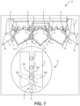
FIG. 7 is top view of the cross track error system showing the resilient members and an aligned row, according to an exemplary embodiment.
FIG. 8 is top view of the cross track error system showing a stalk in motion through the resilient members, according to an exemplary embodiment.
FIG. 9 is top view of the cross track error system showing the resilient members and a mis-aligned row, according to an exemplary embodiment.
FIG. 10 is a graphical representation of individual resilient member deflection, according to one exemplary implementation.
FIG. 11 is another top view of the cross track error system showing the resilient members and a mis-aligned row, according to an exemplary embodiment.
FIG. 12 is another graphical representation of individual resilient member deflection, according to one exemplary implementation.
FIG. 13 is a close-up perspective view of resilient member calibration according to certain implementations of the cross track error system.
FIG. 14 is a close-up perspective view of resilient member calibration according to certain implementations of the cross track error system.
DETAILED DESCRIPTION
The various embodiments disclosed or contemplated herein relate to a corn head cross track error (XTE) sensor and associated systems, methods, and devices for use with an agricultural vehicle, such as a harvester, having an automatic or assisted steering system.
Turning to the figures in greater detail, FIGS. 1 and 2 depict exemplary vehicles 1 having a corn head 2 and assisted steering system 100 configured to harvest row crops. In various implementations such as that of FIG. 2 , a harvester 1 is configured to harvest crops through the row units 6 disposed on the corn head 2, as would be readily appreciated.
The disclosed implementations of the XTE system 10 measure deflection, distance, and or other parameters at the point where stalks enter row unit 6 on the corn head 2. As would be readily appreciated, stalks typically enter the row unit 6 at the stripper deck plate gap 5.
Further, the system 10 in some implementations includes resilient members 20 in communication with and/or disposed on sensor units 22A, 22B. In various implementations, the sensor units 22A, 22B are in communication with a display 12 and/or processor 14 for processing of signals generated by the resilient members 20 and sensor units 22A, 22B. In alternate implementations, the sensor units 22A, 22B can be constructed and arranged like those taught in U.S. patent application Ser. No. 16/445,161, which is incorporated herein by reference for all purposes.
In various implementations, the system 10 may further include a storage medium 16 to store data. In some implementations, the storage 16 may be located on the harvester 1 or alternatively the storage 16 may be cloud 18 based.
Turning to FIG. 3 , in certain implementations, the resilient members 20 are mounted under the front of the stripper plates 4, as disclosed in provisional patent application 62/895,676 filed on Sep. 4, 2019, entitled “Apparatus, Systems and Method for Stalk Sensing,” which is incorporated by reference herein. In these implementations, XTE is measured by comparing the resilient member 20 deflection magnitude and/or duration, as will be discussed further below.
FIGS. 3 and 4 depict exemplary row units 6 of a corn head 2 on a row crop harvester (shown in FIG. 1 at 1). In these implementations of the XTE system 10, each row unit 6 includes a set of stripper plates 4 between dividers 8. As would be understood, stripper plates 4 are configured to break corn or other crops from the stalks as the individual row plants enter the gap 5 defined in the stripper plates 4.
In various implementations, the one or more resilient members 20 are constructed of resilient, elastic material. In these implementations, the resilient members 20 are disposed within the gap 5 and are constructed and arranged to be deflected as stalks pass through the stripper plate gap 5, and more specifically in some implementations as the stalks pass through the entrance to the stripper plates 5A. The resilient members 20 in communication with the sensor units 22A, 22B detect the presence and position of individual stalks as they pass through the row units 6.
Placement of the resilient members 20A, 20B at the entrance 5A to the stripper plates 4 is advantageous because it allows for the assisted steering system 100 to align the stripper plate gap 5 with the row. This alignment between the stripper plate gap 5 and the incoming row of stalks is important for efficient harvesting and maintenance of upright stalks, as described herein.
In various prior known XTE systems, the corn head 2 includes feelers 102 disposed at the front 8A of the snoot (also referred to herein as a “divider” or “row divider”) 8, such as shown in FIG. 5A. These known systems measure XTE at the snoot front 8A ahead of the stripper plate gap 5 and entrance 5A to the stripper plates 4. On most corn heads 3 this snoot front 8A is about three (3) feet ahead of the stripper plate entrance 5A. These prior known XTE systems automatically command a harvester steering system to align the snoot front 8A with the middle of the intermediary space between plant rows, such as to provide equal spacing between the snoot front 8A and the adjacent rows, shown for example in FIG. 5B.
The snoots 8 are straight and thus on curved rows the snoot 8 must be offset in the inter-row space in order to align the stripper plate gap 5 with the incoming stalk row, as shown in FIG. 6 . As such, these prior known systems cause the stripper plate gap 5 to be misaligned with the incoming rows, which can cause the stalks to be pushed to the edges of the stripper plates 4 effecting crop yield.
FIG. 6 illustrates how the snoot front 8A must be offset within the row space to align the stripper plate gap 5 with a curved stalk row. By locating the resilient members 20 and measuring XTE at the target steering point, where stalks enter the stripper plate gap 5, the system 10 keeps the stripper plate gap 5 properly aligned on curved and straight rows.
In various implementations, the geometry and stiffness of the resilient members 20A, 20B and their material composition are configured to provide sufficient restoring force to return the resilient members 20A, 20B to their starting, or neutral position rapidly. It is understood that insufficient restoring force will result in a sluggish return of the resilient members 20A, 20B to their neutral position. For example, if a harvester 1 is traveling at six (6) miles per hour and is harvesting stalks spaced one (1) inch apart the system 10 has about 0.01 seconds to differentiate between the stalks. Accordingly, in certain implementations the resilient members 20A, 20B are configured to have between about 0.25 to about 4 pounds of restoring force urging them back into the neutral position. It is appreciated that certain implementations have a total of about 2 pounds of restoring force applied by the resilient members 20A, 20B.
While a resilient member 20A, 20B may not need to return to the fully neutral position in between stalks, the restoring force must urge the resilient members 20A, 20B far enough toward their neutral position to distinguish between individual stalks. If the system 10, cannot distinguish between individual stalks the signals may appear the same as a corn ear or a mass of vegetation.
Conversely, the resilient members 20A, 20B should not be constructed to have excessive restoring force. Excessive restoring force may increase the likelihood of pushing over incoming stalks and/or causing stalks to bunch and potentially plug the corn head, leading to malfunctions. Proper restoring force will not impede crop flow, but be sufficient to still be capable of detecting closely spaced corn stalks.
In various implementations, the one or more resilient members 20 are made of polyurethane rubber, but may also be constructed of other elastic, viscoelastic, or even metal materials. Exemplary materials include, but are not limited to, nitrile, ethylene propylene diene terpolymer (EPDM), neoprene, natural rubber, silicone, fluro-elastomer, and spring steel. In various additional implementations, the resilient member(s) 20 composition may include the addition of other materials that alter the physical properties of the resulting composite material, as would be recognized by those skilled in the art. Examples include, but are not limited to, inclusion of cellulose, aramid, nylon, glass, or carbon fibers.
Turning now to FIGS. 7 and 8 , the XTE system 10 is further constructed and arranged to ensure that stalks pass through the stripper plate gap 5 vertically. In an exemplary implementation, when there is no XTE the stalks 3 pass through the gap 5 at a stalk axis Sc that is along or substantially aligned with a row unit 6 central axis A. In these implementations, as the stalks 3 pass through the resilient members 20A, 20B, the stalks deflect each of the resilient members 20A, 20B approximately equally.
It is understood that a misalignment of the stalk axis S from the central axis A causes the stripper plate 4 edges to urge the stalks 3 left or right as they pass through the row unit 6. This misalignment results in XTE shown for example in FIGS. 9-12 . Such misalignments are considered steering errors, because they can cause ears to fall off the stalk 3 or push stalks 3 over before the row unit 6 has a chance to strip and gather the ear. These ears may end up on the ground, never to be threshed. As such, to the farmer, they are lost yield and thereby lost profit.
FIGS. 9-10 are examples of a left XTE with respect to forward harvester 1 travel. In this example, the stalk axis Sl is misaligned to the left of the row unit 6 central axis. The XTE caused by the misalignment is measured by the resilient members 20A, 20B and sensor units 22A, 22B. In these implementations, as the resilient members are deflected by the stalks 3 the sensor units 22A, 22B measure the amount of deflection over time. FIG. 10 is a graph of the right and left resilient member 20B, 20A deflection signal. The x-axis is time, the y-axis is resilient member 20A, 20B deflection distance (magnitude). The line with dots on the graph relates to the left resilient member 20B and the line with diamonds relates to the right resilient member 20A. Because plant stalks 3 are fixed to the ground, when there is a left XTE the right stripper plate 4 pushes the stalk 3 to the left as shown in FIG. 9 .
A left XTE, as described above, causes the right resilient member 20A to deflect more and for a longer time than the left resilient member 20B, as shown in FIG. 10 . In a left XTE scenario, the right resilient member 20A is typically the first to deflect and the last to return towards a neutral position, resulting in a longer signal duration. In these implementations, the difference between the right resilient member 20B signal and left resilient member 20A signal deflection is proportional to the extent of the actual left XTE. In some implementations, a XTE calibration curve mathematically relates the difference between left and right resilient member 20A, 20B signal deflection to actual left XTE. In various implementations, the system 10 determines the difference in signal deflection and then calculates an estimated left XTE through the XTE calibration curve. Further, in some implementations, the estimated left XTE is inputted to the steering system 100.
FIGS. 11-12 are examples of a right XTE with respect to forward harvester 1 travel. The descriptions for left XTE above also apply to FIGS. 11-12 . In this example, the stalk axis Sr is misaligned to the right of the row unit 6 central axis A such that the stalk 3 is pushed to the right, and the left resilient member 20B deflection signal is larger than the right resilient member's 20A deflection signal. The difference between the left resilient member 20B signal and right resilient member 20A signal deflection is proportional to the extent of the actual right XTE. In some implementations, a XTE calibration curve mathematically relates the difference between left and right resilient member 20A, 20B signal deflection to actual right XTE. In various implementations, the system 10 determines the difference in signal deflection and then calculates an estimated right XTE through the XTE calibration curve. Further, in some implementations, the estimated right XTE is inputted to the steering system 100.
By computing or integrating the area under the curve value of each resilient member 20A, 20B deflection signal, a mathematical value can be calculated and calibrated to an accurate XTE. Several other mathematical techniques may exist to compare the left and right resilient member 20A, 20B deflection signals. In various implementations, the ground speed, stalk 3 population per area, header 2 height, and stalk 3 size (e.g. diameter) variations can cause variations in the deflection signals. All these parameters may change during a harvest operation. A system requiring unique XTE calibrations for all of these parameter variations is likely too burdensome for the harvester 1 operator to perform. Further accounting for each of these parameters introduces too many sources of potential error. In various implementations, mathematical left and right resilient member 20A, 20B comparison technique that requires only one XTE calibration is used by the system 10.
A ratio method of area under the curve of each resilient member 20A, 20B deflection signal can utilize one XTE calibration for ground speed, stalk population, header height and stalk size variations. Exemplary ratios may be:
Right Resilient Member Deflection Signal Left Resilient Member Deflection Signal or Left Resilient Member Deflection Signal Right Resilient Member Deflection Signal
In various implementations, the stripper plates 4 can be manually or automatically adjusted to increase or decrease the stripper plate gap 5, as discussed in U.S. Provisional Patent Application 63/006,774, filed Apr. 8, 2020, and entitled “Agricultural Devices, Systems, and Methods”. In various implementations, the stripper plate gap 5 width is adjusted in accordance with stalk 3 size variations. Various corn head 2 configurations may adjust one or both plates 4. In these implementations, adjustment of the stripper plate 4 gap may change the XTE calibration if the resilient members 20A, 20B do not move with the stripper plates 4. In this case, a new calibration may be performed manually at the sensor as shown in FIGS. 13-14 .
In these implementations, to calibrate the system 10 the outside edge of each resilient member 20A, 20B is held vertically flush to the stripper plate 4 edge with a straight edge 7 or jig 7. The system 10 may then record a resilient member 20A, 20B deflection signal set point that corresponds to the stripper plate 4 edge position relative to the resilient member. This process is independently performed for the left and right resilient members 20A, 20B.
In various implementations, the system 10 uses the resilient member 20A, 20B set points to switch to a different predetermined XTE calibration that corresponds to the stripper plate 4 edge position/stripper plate gap 5. The calibration from one row unit 6 may be applied to all other row units 6, or separate calibrations can be performed on each row unit 6.
In a further implementation, each resilient member 20A, 20B may detect the location of the stripper plate 4 edge relative to the resilient member 20A, 20B using a stripper plate 4 edge sensor affixed to the resilient member 20A, 20B or to the stripper plate 4.
In various of these implementations, the system 10 may automatically obtain the stripper plate gap 5 setting/resilient member set points from a storage 16 or memory. In these implementations, the XTE system 10 applies predetermined calibrations unique to each harvester 1 stripper plate 4 edge or gap 5 setting as appropriate. These calibrations may be stored in a look up table in the storage 16 or other memory.
The harvester automatic steering system 100 and the XTE system 10 disclosed herein may be used in conjunction with various heading error detection methods to improve performance on curves, certain exemplary heading error detection methods are set forth below.
One exemplary heading error detection method includes the use of GPS path recordings from prior machine operations. This includes, but is not limited to, path recordings from prior planting, pesticide, and fertilizer machine operations. In some of these implementations, the path recordings are from prior machines automatically steered by row recognition systems similar to those taught in U.S. Pat. No. 9,964,559, which is incorporated here by reference in its entirety. In these implementations, to determine heading error, the automatic steering system 100 selects a near prior machine path and assumes the harvester path curvature will be the same as the prior path curvature.
Another exemplary heading error detection method includes the use of GPS path recordings of the in-situ harvester 1. To determine heading error, the harvester steering system 100 selects a near prior harvester 1 pass from the current harvest operation and assumes the harvester 1 path curvature will be the same as the prior path curvature.
In various implementations, the automatic steering system 100 may steer solely on XTE feedback from the resilient members 20A, 20B and sensor units 22A, 22B. This is possible because the XTE system 10 measures XTE at the target steering point. That is, in various implementations, the steering system 100 is able to steer without heading error.
As would be appreciated, the resilient members 20A, 20B, sensor units 22A, 22B, and system 10 may be used simultaneously to perform various other functions. For example, counting and sizing stalks, detecting a plugged row unit, detecting ear shelling, and other functions as would be recognized. Further, any combination of these functions may be used in conjunction with the disclosed XTE system 10 and steering system 100.
Although the disclosure has been described with reference to preferred embodiments, persons skilled in the art will recognize that changes may be made in form and detail without departing from the spirit and scope of the disclosed apparatus, systems and methods.

Claims (16)

What is claimed is:
1. A system comprising:
a) a row unit;
b) a set of stripper plates disposed on the row unit, the stripper plates defining a stripper plate gap;
c) a pair of resilient members disposed on the row unit and extending into the stripper plate gap configured to contact stalks as stalks enter the row unit;
d) a sensor in communication with each resilient member of the pair of resilient members, the sensors constructed and arranged to measure deflection of each of the resilient members as a stalk passes through the row unit; and
(e) a processor in communication with each sensor,
wherein the processor is configured process deflection signals generated by the sensor, and wherein the processor is configured to sense misalignment of the stalk relative to the stripper plate gap as the stalk passes through the row unit via comparison of deflection of individual resilient members of the pair of resilient members.
2. The system of claim 1, wherein misalignment of the stalk corresponds to cross track error.
3. The system of claim 2, wherein the row unit is disposed on a corn head attached to a harvester.
4. The system of claim 3, wherein the system is further configured to command an automated steering system to steer the harvester to correct cross track error.
5. The system of claim 3, wherein the system is configured to command an automated steering system to align the stripper plate gap with an incoming plant row comprising one or more stalks.
6. The system of claim 5, further comprising a display in communication with the sensor.
7. The system of claim 6, wherein the pair of resilient members is comprised of polyurethane rubber.
8. A method comprising:
measuring magnitude or duration of deflection of a first resilient member and a second resilient member via a sensor, the first and second resilient members disposed on a row unit comprising a set of stripper plates defining a stripper plate gap and wherein the first resilient member and second resilient member extend into the stripper plate gap, the row unit disposed on a harvester, and
sensing alignment of a stalk with the stripper plate gap as the stalk passes though the row unit via comparison of the magnitude or duration of deflection of the first resilient member with the magnitude or duration of deflection of the second resilient member.
9. The method of claim 8, wherein the first and second resilient members are deflected when corn stalks enter the row unit.
10. The method of claim 8, further comprising:
determining a difference between the deflection of the first resilient member and the deflection of the second resilient member; and
steering the harvester in response to the difference.
11. The method of claim 8, further comprising adjusting a width of the stripper plate gap.
12. The method of claim 8, further comprising detecting heading error.
13. A system comprising:
(a) a corn head;
(b) at least one row unit disposed on the corn head, the at least one row unit comprising:
(i) a set of stripper plates;
(ii) a first resilient member and a second resilient member each disposed proximal to the stripper plates and extending into a gap between the stripper plates; and
(iii) at least one sensor unit in communication with the first resilient member and second resilient member; and
(c) a processor;
wherein the processor is constructed and arranged to process signals generated by the at least one sensor unit in response to deflection of the first resilient member and second resilient member, wherein the processor is configured to detect a stalk alignment with the gap between the stripper plates as a stalk passes through the at least one row unit via comparison of deflection of the first resilient member with deflection of the second resilient member.
14. The system of claim 13, wherein alignment of the stalk corresponds to cross track error.
15. The system of claim 13, configured to command an automated steering system to align the gap between the stripper plates with an incoming plant row comprising one or more stalks.
16. The system of claim 13, wherein the first resilient member and second resilient member are comprised of polyurethane rubber.
US16/918,300 2020-07-01 2020-07-01 Apparatus, systems and methods for eliminating cross-track error Active 2040-10-31 US11678607B2 (en)

Priority Applications (2)

Application Number Priority Date Filing Date Title
US16/918,300 US11678607B2 (en) 2020-07-01 2020-07-01 Apparatus, systems and methods for eliminating cross-track error
US18/132,088 US20230240185A1 (en) 2020-07-01 2023-04-07 Apparatus, Systems And Methods For Eliminating Cross-Track Error

Applications Claiming Priority (1)

Application Number Priority Date Filing Date Title
US16/918,300 US11678607B2 (en) 2020-07-01 2020-07-01 Apparatus, systems and methods for eliminating cross-track error

Related Child Applications (1)

Application Number Title Priority Date Filing Date
US18/132,088 Continuation US20230240185A1 (en) 2020-07-01 2023-04-07 Apparatus, Systems And Methods For Eliminating Cross-Track Error

Publications (2)

Publication Number Publication Date
US20220000024A1 US20220000024A1 (en) 2022-01-06
US11678607B2 true US11678607B2 (en) 2023-06-20

Family

ID=79166262

Family Applications (2)

Application Number Title Priority Date Filing Date
US16/918,300 Active 2040-10-31 US11678607B2 (en) 2020-07-01 2020-07-01 Apparatus, systems and methods for eliminating cross-track error
US18/132,088 Pending US20230240185A1 (en) 2020-07-01 2023-04-07 Apparatus, Systems And Methods For Eliminating Cross-Track Error

Family Applications After (1)

Application Number Title Priority Date Filing Date
US18/132,088 Pending US20230240185A1 (en) 2020-07-01 2023-04-07 Apparatus, Systems And Methods For Eliminating Cross-Track Error

Country Status (1)

Country Link
US (2) US11678607B2 (en)

Cited By (1)

* Cited by examiner, † Cited by third party
Publication number Priority date Publication date Assignee Title
US20220317688A1 (en) * 2021-04-01 2022-10-06 Fj Dynamics Technology Co., Ltd Automatic row alignment driving system and method for high stem crop harvester

Families Citing this family (4)

* Cited by examiner, † Cited by third party
Publication number Priority date Publication date Assignee Title
US20210059114A1 (en) * 2019-09-04 2021-03-04 Ag Leader Technology Apparatus, Systems And Methods For Stalk Sensing
US20210329838A1 (en) * 2019-09-04 2021-10-28 Ag Leader Technology Apparatus, Systems And Methods For Stalk Sensing
US20240049638A1 (en) * 2022-08-12 2024-02-15 Cnh Industrial America Llc Active deck plate opening
US20240125661A1 (en) * 2022-10-14 2024-04-18 Cnh Industrial America Llc Damping systems and methods for impact sensing on an agricultural header

Citations (60)

* Cited by examiner, † Cited by third party
Publication number Priority date Publication date Assignee Title
US3038544A (en) * 1958-11-03 1962-06-12 Ford Motor Co Tractor steering means
US3178873A (en) * 1961-08-04 1965-04-20 Lester L Meyer Tobacco cutter and spudder
DE1928065A1 (en) * 1968-07-17 1970-05-14 Epple Buxbaum Werke Automatic side control for a self-propelled machine for harvesting plants standing in rows
US3972381A (en) * 1974-07-17 1976-08-03 Maschinenfabrik Fahr Aktiengesellschaft Sensor arrangement for harvester of stalk-type row crop
US4126984A (en) * 1975-12-09 1978-11-28 Maschinenfabrik Fahr Ag Gottmadingen Apparatus for the automatic lateral guidance of agricultural machines
US4166349A (en) 1977-02-10 1979-09-04 Firma Gebr. Claas Maschinenfabrik GmbH Sensing device for guiding a harvest machine
US4295323A (en) * 1979-03-30 1981-10-20 Klockner-Humboldt-Deutz AG (Zweigniederlassung Fahr) Towed crop harvester
US4505094A (en) * 1983-09-06 1985-03-19 Deere & Company Row crop harvester guidance system control circuit
US4528804A (en) * 1983-09-06 1985-07-16 Deere & Company Sensing unit for row crop harvester guidance system
US4883964A (en) 1988-12-22 1989-11-28 Ford New Holland, Inc. Optical method and apparatus for discriminating between crop stalks and weed stalks in a non-contact row crop harvester guidance system
US4918441A (en) 1988-12-22 1990-04-17 Ford New Holland, Inc. Non-contact sensing unit for row crop harvester guidance system
US4967362A (en) * 1989-01-30 1990-10-30 Eaton Corporation Automatic steering apparatus for crop vehicle
US5044210A (en) 1990-11-01 1991-09-03 Pioneer Hi-Bred International, Inc. Method and means for testing the strength of plant stalks
US5568405A (en) 1994-11-23 1996-10-22 Easton Goers, Inc. Device to measure and provide data for plant population and spacing variability
US5598794A (en) 1995-02-13 1997-02-04 Fluid Power Industries, Inc. High accuracy automatically controlled variable linear seed spacing planting apparatus
US5790428A (en) 1994-11-23 1998-08-04 Easton Goers, Inc. Device to measure and provide data for plant population and spacing variability
US5878561A (en) 1996-10-31 1999-03-09 Gunn; Ira I. Row crop harvester
US5991694A (en) 1995-11-13 1999-11-23 Caterpillar Inc. Method and apparatus for determining the location of seedlings during agricultural production
US6073427A (en) 1998-06-11 2000-06-13 Nichols; Stephen W. Method and apparatus for counting crops
US6085846A (en) 1999-07-01 2000-07-11 Automatic Depth Control, Llc Potentiometer-based gauge wheel device positioning system and method
US6119442A (en) 1999-05-14 2000-09-19 Case Corporation Combine setting autoadjust with machine vision
CA2313376A1 (en) 1999-07-01 2001-01-01 Andrew F. Buchl Automatic depth control system and method
US6216795B1 (en) 1999-07-01 2001-04-17 Andrew F. Buchl Ultrasonic transducer based device positioning system and method
US6584390B2 (en) 2001-06-28 2003-06-24 Deere & Company System for measuring the amount of crop to be harvested
US6668223B2 (en) 2001-03-08 2003-12-23 Deere & Company Crop width measuring apparatus
US6983582B1 (en) 2003-08-01 2006-01-10 Muckler Gregory A Stalk strength tester
US7401528B2 (en) 2006-06-22 2008-07-22 Monsanto Technology Llc Apparatus and methods for evaluating plant stalk strength
US7716905B2 (en) * 2008-05-16 2010-05-18 Deere & Company Sensing assembly for detection of one or more plants
US7916898B2 (en) 2003-09-15 2011-03-29 Deere & Company Method and system for identifying an edge of a crop
US8010261B2 (en) 2007-05-23 2011-08-30 Cnh America Llc Automatic steering correction of an agricultural harvester using integration of harvester header row sensors and harvester auto guidance system
US8196380B2 (en) 2009-12-18 2012-06-12 Olimac S.R.L. Machine for decreasing force exerted on maize during harvesting
US8224534B2 (en) 2010-07-27 2012-07-17 Cnh America Llc System and method for automatically controlling deck plate position on a corn header
US8220235B2 (en) 2010-01-19 2012-07-17 Cnh America Llc Corn head stripper plate adjusting mechanism
US8418636B2 (en) 2010-08-20 2013-04-16 Deere & Company In-ground seed spacing monitoring system for use in an agricultural seeder
US9030549B2 (en) 2012-03-07 2015-05-12 Blue River Technology, Inc. Method and apparatus for automated plant necrosis
US9066463B2 (en) 2012-10-02 2015-06-30 Trimble Navigation Limited Crop feeler system and method
US20150334920A1 (en) * 2014-05-20 2015-11-26 Deere & Company Method and system for sensing a position of a vehicle or guiding a vehicle with respect to one or more plant rows
US9232693B2 (en) 2014-05-08 2016-01-12 Deere & Company System and method for sensing and mapping stalk diameter
US9282693B2 (en) 2013-02-20 2016-03-15 Deere & Company Data encoding with planting attributes
US9310329B2 (en) 2013-03-15 2016-04-12 Raven Industries, Inc. Remote moisture sensor and methods for the same
US9320196B2 (en) 2013-02-20 2016-04-26 Deere & Company Stripper plate adjustment
US9322629B2 (en) 2011-11-22 2016-04-26 Precision Planting Llc Stalk sensor apparatus, systems, and methods
US9372109B2 (en) 2013-03-15 2016-06-21 Raven Industires, Inc. Harvester elevator in-flow weight sensor and methods for the same
US9410840B2 (en) 2013-03-15 2016-08-09 Raven Industries, Inc. Multi-variable yield monitor and methods for the same
US9565802B2 (en) 2014-05-20 2017-02-14 Deere & Company Crop sensing system and method with immediate gap detection
US9658201B2 (en) 2013-03-07 2017-05-23 Blue River Technology Inc. Method for automatic phenotype measurement and selection
US9717171B2 (en) 2013-03-07 2017-08-01 Blue River Technology Inc. System and method for automated odometry calibration for precision agriculture systems
US9867335B1 (en) 2016-02-01 2018-01-16 Brian R. Obbink Automatic tensioning control deck plate system
US9867334B2 (en) 2014-10-27 2018-01-16 Cnh Industrial America Llc Corn header including a kernel sensor and a control unit for controlling desk plates of the corn header
US9921064B2 (en) 2015-10-30 2018-03-20 Deere & Company Method and system for guidance of off-road vehicles
US9936631B1 (en) 2016-09-30 2018-04-10 Deere & Company Device and method for detecting and reporting seed placement
US9936637B2 (en) 2015-05-14 2018-04-10 Deere & Company Combine harvester combining row crop guidance and plant attribute measurement
US10034424B2 (en) 2016-05-24 2018-07-31 Deere & Company Crop attribute sensing with crop loss inhibitors
US10039231B2 (en) 2015-05-19 2018-08-07 Deere & Company System for measuring plant attributes using a priori plant maps
US20180373259A1 (en) * 2017-06-22 2018-12-27 360 Yield Center, Llc Enhanced automated steering system for a vehicle
US20190000007A1 (en) * 2017-06-30 2019-01-03 Deere & Company Crop row sensing on vehicle with multiple, independently steerable axles/wheels
US10820508B2 (en) 2018-08-20 2020-11-03 Cnh Industrial America Llc System and method for operating an agricultural harvester
US10859479B2 (en) 2017-12-21 2020-12-08 Pioneer Hi-Bred International, Inc. Non-destructive stalk and root contact sensor with variable rate tensioner
US20210168991A1 (en) * 2019-12-05 2021-06-10 Cnh Industrial America Llc System and method for controlling the direction of travel of a work vehicle based on an adjusted guidance line
US20210329838A1 (en) * 2019-09-04 2021-10-28 Ag Leader Technology Apparatus, Systems And Methods For Stalk Sensing

Patent Citations (67)

* Cited by examiner, † Cited by third party
Publication number Priority date Publication date Assignee Title
US3038544A (en) * 1958-11-03 1962-06-12 Ford Motor Co Tractor steering means
US3178873A (en) * 1961-08-04 1965-04-20 Lester L Meyer Tobacco cutter and spudder
DE1928065A1 (en) * 1968-07-17 1970-05-14 Epple Buxbaum Werke Automatic side control for a self-propelled machine for harvesting plants standing in rows
US3972381A (en) * 1974-07-17 1976-08-03 Maschinenfabrik Fahr Aktiengesellschaft Sensor arrangement for harvester of stalk-type row crop
US4126984A (en) * 1975-12-09 1978-11-28 Maschinenfabrik Fahr Ag Gottmadingen Apparatus for the automatic lateral guidance of agricultural machines
US4166349A (en) 1977-02-10 1979-09-04 Firma Gebr. Claas Maschinenfabrik GmbH Sensing device for guiding a harvest machine
US4295323A (en) * 1979-03-30 1981-10-20 Klockner-Humboldt-Deutz AG (Zweigniederlassung Fahr) Towed crop harvester
US4528804A (en) * 1983-09-06 1985-07-16 Deere & Company Sensing unit for row crop harvester guidance system
US4505094A (en) * 1983-09-06 1985-03-19 Deere & Company Row crop harvester guidance system control circuit
US4883964A (en) 1988-12-22 1989-11-28 Ford New Holland, Inc. Optical method and apparatus for discriminating between crop stalks and weed stalks in a non-contact row crop harvester guidance system
US4918441A (en) 1988-12-22 1990-04-17 Ford New Holland, Inc. Non-contact sensing unit for row crop harvester guidance system
US4967362A (en) * 1989-01-30 1990-10-30 Eaton Corporation Automatic steering apparatus for crop vehicle
US5044210A (en) 1990-11-01 1991-09-03 Pioneer Hi-Bred International, Inc. Method and means for testing the strength of plant stalks
US5568405A (en) 1994-11-23 1996-10-22 Easton Goers, Inc. Device to measure and provide data for plant population and spacing variability
US5790428A (en) 1994-11-23 1998-08-04 Easton Goers, Inc. Device to measure and provide data for plant population and spacing variability
US5598794A (en) 1995-02-13 1997-02-04 Fluid Power Industries, Inc. High accuracy automatically controlled variable linear seed spacing planting apparatus
US5991694A (en) 1995-11-13 1999-11-23 Caterpillar Inc. Method and apparatus for determining the location of seedlings during agricultural production
US5878561A (en) 1996-10-31 1999-03-09 Gunn; Ira I. Row crop harvester
US6073427A (en) 1998-06-11 2000-06-13 Nichols; Stephen W. Method and apparatus for counting crops
US6119442A (en) 1999-05-14 2000-09-19 Case Corporation Combine setting autoadjust with machine vision
US6085846A (en) 1999-07-01 2000-07-11 Automatic Depth Control, Llc Potentiometer-based gauge wheel device positioning system and method
CA2313376A1 (en) 1999-07-01 2001-01-01 Andrew F. Buchl Automatic depth control system and method
US6216795B1 (en) 1999-07-01 2001-04-17 Andrew F. Buchl Ultrasonic transducer based device positioning system and method
US6668223B2 (en) 2001-03-08 2003-12-23 Deere & Company Crop width measuring apparatus
US6584390B2 (en) 2001-06-28 2003-06-24 Deere & Company System for measuring the amount of crop to be harvested
US6983582B1 (en) 2003-08-01 2006-01-10 Muckler Gregory A Stalk strength tester
US7916898B2 (en) 2003-09-15 2011-03-29 Deere & Company Method and system for identifying an edge of a crop
US7401528B2 (en) 2006-06-22 2008-07-22 Monsanto Technology Llc Apparatus and methods for evaluating plant stalk strength
US8010261B2 (en) 2007-05-23 2011-08-30 Cnh America Llc Automatic steering correction of an agricultural harvester using integration of harvester header row sensors and harvester auto guidance system
US7716905B2 (en) * 2008-05-16 2010-05-18 Deere & Company Sensing assembly for detection of one or more plants
US8196380B2 (en) 2009-12-18 2012-06-12 Olimac S.R.L. Machine for decreasing force exerted on maize during harvesting
US8220235B2 (en) 2010-01-19 2012-07-17 Cnh America Llc Corn head stripper plate adjusting mechanism
US8224534B2 (en) 2010-07-27 2012-07-17 Cnh America Llc System and method for automatically controlling deck plate position on a corn header
US8418636B2 (en) 2010-08-20 2013-04-16 Deere & Company In-ground seed spacing monitoring system for use in an agricultural seeder
US10537060B2 (en) 2011-11-22 2020-01-21 The Climate Corporation Stalk sensor apparatus, systems, and methods
US9894835B2 (en) 2011-11-22 2018-02-20 The Climate Corporation Stalk sensor apparatus, systems, and methods
US9322629B2 (en) 2011-11-22 2016-04-26 Precision Planting Llc Stalk sensor apparatus, systems, and methods
US9030549B2 (en) 2012-03-07 2015-05-12 Blue River Technology, Inc. Method and apparatus for automated plant necrosis
US9064173B2 (en) 2012-03-07 2015-06-23 Blue River Technology, Inc. Method and apparatus for automated plant necrosis
US9756771B2 (en) 2012-03-07 2017-09-12 Blue River Technology Inc. Method and apparatus for automated plant necrosis
US9066463B2 (en) 2012-10-02 2015-06-30 Trimble Navigation Limited Crop feeler system and method
US9320196B2 (en) 2013-02-20 2016-04-26 Deere & Company Stripper plate adjustment
US9693503B2 (en) 2013-02-20 2017-07-04 Deere & Company Crop sensing
US9282693B2 (en) 2013-02-20 2016-03-15 Deere & Company Data encoding with planting attributes
US9832928B2 (en) 2013-02-20 2017-12-05 Deere & Company Crop sensing
US9658201B2 (en) 2013-03-07 2017-05-23 Blue River Technology Inc. Method for automatic phenotype measurement and selection
US9717171B2 (en) 2013-03-07 2017-08-01 Blue River Technology Inc. System and method for automated odometry calibration for precision agriculture systems
US9372109B2 (en) 2013-03-15 2016-06-21 Raven Industires, Inc. Harvester elevator in-flow weight sensor and methods for the same
US9410840B2 (en) 2013-03-15 2016-08-09 Raven Industries, Inc. Multi-variable yield monitor and methods for the same
US9310329B2 (en) 2013-03-15 2016-04-12 Raven Industries, Inc. Remote moisture sensor and methods for the same
US9232693B2 (en) 2014-05-08 2016-01-12 Deere & Company System and method for sensing and mapping stalk diameter
US9565802B2 (en) 2014-05-20 2017-02-14 Deere & Company Crop sensing system and method with immediate gap detection
US20150334920A1 (en) * 2014-05-20 2015-11-26 Deere & Company Method and system for sensing a position of a vehicle or guiding a vehicle with respect to one or more plant rows
US9867334B2 (en) 2014-10-27 2018-01-16 Cnh Industrial America Llc Corn header including a kernel sensor and a control unit for controlling desk plates of the corn header
US9936637B2 (en) 2015-05-14 2018-04-10 Deere & Company Combine harvester combining row crop guidance and plant attribute measurement
US10039231B2 (en) 2015-05-19 2018-08-07 Deere & Company System for measuring plant attributes using a priori plant maps
US9921064B2 (en) 2015-10-30 2018-03-20 Deere & Company Method and system for guidance of off-road vehicles
US9927242B2 (en) 2015-10-30 2018-03-27 Deere & Company Method and system for guidance of off-road vehicles
US9867335B1 (en) 2016-02-01 2018-01-16 Brian R. Obbink Automatic tensioning control deck plate system
US10034424B2 (en) 2016-05-24 2018-07-31 Deere & Company Crop attribute sensing with crop loss inhibitors
US9936631B1 (en) 2016-09-30 2018-04-10 Deere & Company Device and method for detecting and reporting seed placement
US20180373259A1 (en) * 2017-06-22 2018-12-27 360 Yield Center, Llc Enhanced automated steering system for a vehicle
US20190000007A1 (en) * 2017-06-30 2019-01-03 Deere & Company Crop row sensing on vehicle with multiple, independently steerable axles/wheels
US10859479B2 (en) 2017-12-21 2020-12-08 Pioneer Hi-Bred International, Inc. Non-destructive stalk and root contact sensor with variable rate tensioner
US10820508B2 (en) 2018-08-20 2020-11-03 Cnh Industrial America Llc System and method for operating an agricultural harvester
US20210329838A1 (en) * 2019-09-04 2021-10-28 Ag Leader Technology Apparatus, Systems And Methods For Stalk Sensing
US20210168991A1 (en) * 2019-12-05 2021-06-10 Cnh Industrial America Llc System and method for controlling the direction of travel of a work vehicle based on an adjusted guidance line

Non-Patent Citations (20)

* Cited by examiner, † Cited by third party
Title
"AutoTrac RowSense", Precision AG,, Page(s) https://www.deere.com/sub-saharan/en/technology-products/precision-ag/autotrac-rowsense/, Publisher: John Deere SSA, Jan. 20, 2021.
"Harvest Study Reveals most corn heads leaving yield in the field.", 2020 Special Report, 2020, Row by Row.
Baweja et al., "StalkNet: A Deep Learning Pipeline for High-throughput Measurement of Plant Stalk Count and Stalk Width", 2018.
Birrell et al., "Corn Population Sensor for Precision Farming", American Society of Agricultural Engineers. Annual Meeting, 1995, vol. 95, No. 1334, Publisher: ASAE.
D. Easton, "Corn Population and Plant Spacing Variability: The Next Mapping Layer", 1996, pp. 723-727, Publisher: ASA-CSSA-SSSA, Published in: Madison, WI.
FARM SHOW, "Easton Goers, Inc. Space Wheel Checks Seed Placement In Field—Space Cadet", 1996, Publisher: FARM SHOW.
Haizhou Li, "Design and Evaluation of a Non-Intrusive Con Population Sensor", Trace: Tennessee Research and Creative Exchange, Doctoral Dissertations, Graduate School, Aug. 2007, Publisher: University of Tennessee, Knoxville.
Headsight, Inc., "Row Guidance for Corn", Jan. 2021, https://headsight.com/row-guidance-corn.
Headsight, Inc., Row Guidance for Corn, Jan. 2021, Page(s) https://headsight.com/row-guidance-com, Publisher: Headsight, Inc.
Hummel et al., "Sensing Corn Population—Another Variable in the Yield Equation", Jan. 19, 2015.
John Deere SSA, "AutoTrac RowSense | Precision AG | John Deere SSA", Jan. 2021, https://www.deere.com/sub-saharan/en/technology-products/precision-ag/autotrac-rowsense/.
Jonathan P. Kelly, "By-Plant Prediction of Corn Grain Yield Using Height and Stalk Diameter", 2009, Publisher: Faculty of the Graduate College of the Oklahoma State University.
Luck et al., "Sensor Ranging Technique for Determining Com Plant Population", Faculty Papers and Publications in Animal Science—Animal Science Department, 2008, vol. 920, Publisher: University of Nebraska—Lincoln.
Plattner et al., "Corn Plant Population Sensor for Precision Agriculture", 1996.
Reichhardt Electronic Innovations, "PSR Sensor Guidance", , Page(s) www.reichhardt.com/us_products_autosteer-systems_autoguidance-tac.html, Publisher: Reichhardt Electronic Innovations, Jan. 20, 2021.
Reichhardt Electronic Innovations, "PSR Sensor Guidance", Jan. 2021, www.reichhardt.com/us_products_autosteer-system_autoguidance-tac.html.
Shrestha et al., "Automatic Corn Plant Population Measurement Using Machine Vision", Transactions of the ASAE, 2003, pp. 559-565, vol. 46(2), Publisher: American Society of Agricultural Engineers.
Sudduth et al., "Field Evaluation of a Corn Population Sensor", 2000.
Yeyin Shi, "Corn Plant Location, Spacing and Stalk Diameter Measurements Using Optical Sensing Technologies", May 2014, Publisher: Faculty of the Graduate College of the Oklahoma State University.
Yu et al., "Outlier Elimination for Robust Ellipse and Ellipsoid Fitting", Oct. 24, 2009.

Cited By (1)

* Cited by examiner, † Cited by third party
Publication number Priority date Publication date Assignee Title
US20220317688A1 (en) * 2021-04-01 2022-10-06 Fj Dynamics Technology Co., Ltd Automatic row alignment driving system and method for high stem crop harvester

Also Published As

Publication number Publication date
US20220000024A1 (en) 2022-01-06
US20230240185A1 (en) 2023-08-03

Similar Documents

Publication Publication Date Title
US11678607B2 (en) Apparatus, systems and methods for eliminating cross-track error
US9936637B2 (en) Combine harvester combining row crop guidance and plant attribute measurement
US11950529B2 (en) Stalk sensor apparatus, systems, and methods
EP3095313B1 (en) System for measuring plant attributes using a priori plant maps
US8010261B2 (en) Automatic steering correction of an agricultural harvester using integration of harvester header row sensors and harvester auto guidance system
BR102015011138B1 (en) Crop yield sensing apparatus and method
US11687083B2 (en) Comparative agricultural obstacle monitor and guidance system and method for same
US9485914B2 (en) Method and system for sensing a position of a vehicle or guiding a vehicle with respect to one or more plant rows
EP2020168A1 (en) Control system for agricultural working vehicles
BR102015017990B1 (en) biomass sensing apparatus
US10267820B2 (en) Apparatus, systems and methods for cross track error calculation from active sensors
US20210329838A1 (en) Apparatus, Systems And Methods For Stalk Sensing
US4197690A (en) Position detector for row-crop harvester
JP2003070339A (en) Yield-measuring device in combine harvester
EP3000304B1 (en) Aggregate yield allocation
EP0381073B1 (en) Automatic guidance apparatus for a vehicule
US20210059114A1 (en) Apparatus, Systems And Methods For Stalk Sensing
US11589511B2 (en) Control system and method for controlling a position of a header of an agricultural harvester
US20230292664A1 (en) Cross track error sensor and related devices, systems, and methods
CN115373397A (en) Automatic right-to-go control method and device, working vehicle and storage medium
US5419105A (en) Structure for and method of bunching limbs of cotton plants
JPS6150561B1 (en)
JPS6143914A (en) Automatic steering controller of moving harvester
JPH11346506A (en) Direction controlling apparatus for combine

Legal Events

Date Code Title Description
FEPP Fee payment procedure

Free format text: ENTITY STATUS SET TO UNDISCOUNTED (ORIGINAL EVENT CODE: BIG.); ENTITY STATUS OF PATENT OWNER: SMALL ENTITY

FEPP Fee payment procedure

Free format text: ENTITY STATUS SET TO SMALL (ORIGINAL EVENT CODE: SMAL); ENTITY STATUS OF PATENT OWNER: SMALL ENTITY

AS Assignment

Owner name: AG LEADER TECHNOLOGY, IOWA

Free format text: ASSIGNMENT OF ASSIGNORS INTEREST;ASSIGNORS:ZIELKE, ROGER;EICHHORN, SCOTT;REEL/FRAME:053420/0499

Effective date: 20200805

STPP Information on status: patent application and granting procedure in general

Free format text: DOCKETED NEW CASE - READY FOR EXAMINATION

STPP Information on status: patent application and granting procedure in general

Free format text: NON FINAL ACTION MAILED

STPP Information on status: patent application and granting procedure in general

Free format text: RESPONSE TO NON-FINAL OFFICE ACTION ENTERED AND FORWARDED TO EXAMINER

STPP Information on status: patent application and granting procedure in general

Free format text: FINAL REJECTION MAILED

STCF Information on status: patent grant

Free format text: PATENTED CASE