US11669210B2 - Optical touch sensor - Google Patents
Optical touch sensor Download PDFInfo
- Publication number
- US11669210B2 US11669210B2 US17/487,195 US202117487195A US11669210B2 US 11669210 B2 US11669210 B2 US 11669210B2 US 202117487195 A US202117487195 A US 202117487195A US 11669210 B2 US11669210 B2 US 11669210B2
- Authority
- US
- United States
- Prior art keywords
- light
- beams
- lenses
- detection area
- detectors
- Prior art date
- Legal status (The legal status is an assumption and is not a legal conclusion. Google has not performed a legal analysis and makes no representation as to the accuracy of the status listed.)
- Active
Links
Images


Classifications
-
- G—PHYSICS
- G06—COMPUTING; CALCULATING OR COUNTING
- G06F—ELECTRIC DIGITAL DATA PROCESSING
- G06F3/00—Input arrangements for transferring data to be processed into a form capable of being handled by the computer; Output arrangements for transferring data from processing unit to output unit, e.g. interface arrangements
- G06F3/01—Input arrangements or combined input and output arrangements for interaction between user and computer
- G06F3/03—Arrangements for converting the position or the displacement of a member into a coded form
- G06F3/041—Digitisers, e.g. for touch screens or touch pads, characterised by the transducing means
- G06F3/042—Digitisers, e.g. for touch screens or touch pads, characterised by the transducing means by opto-electronic means
- G06F3/0421—Digitisers, e.g. for touch screens or touch pads, characterised by the transducing means by opto-electronic means by interrupting or reflecting a light beam, e.g. optical touch-screen
-
- G—PHYSICS
- G02—OPTICS
- G02B—OPTICAL ELEMENTS, SYSTEMS OR APPARATUS
- G02B5/00—Optical elements other than lenses
- G02B5/02—Diffusing elements; Afocal elements
- G02B5/0205—Diffusing elements; Afocal elements characterised by the diffusing properties
Definitions
- the field of the present invention is touchscreens, particularly optical touchscreens.
- FIG. 1 is a simplified illustration of a first prior art optical touchscreen, described in U.S. Pat. No. 9,471,170, entitled LIGHT-BASED TOUCH SCREEN WITH SHIFT-ALIGNED EMITTER AND RECEIVER LENSES, and assigned to the assignee of the present invention.
- This touchscreen 900 is surrounded by lens arrays 300 - 303 .
- Emitters 100 - 121 are arranged along two adjacent edges of the touchscreen, and detectors 200 - 223 are arranged along the remaining two edges.
- the emitters along edges of the touchscreen are shift-aligned with respect to the detectors along the opposite edges of the touchscreen.
- Lenses 300 and 301 are configured to spread light from each emitter to arrive at two opposite detectors, and lenses 302 and 303 are configured such that each detector receives light from two opposite emitters.
- FIG. 1 shows horizontal light beams 400 - 407 and vertical light beams 408 - 421 , each beam originating at a respective emitter and reaching two detectors. Each emitter is synchronously activated with its corresponding detectors by processor 901 . Processor 901 also stores the detector outputs and calculates touch locations based on these outputs.
- FIG. 2 is a simplified illustration of a second prior art optical touchscreen, described in U.S. Pat. No. 9,063,614, entitled OPTICAL TOUCH SCREENS, and assigned to the assignee of the present invention.
- This touchscreen 902 is surrounded by lens arrays 304 - 307 .
- Emitters 122 - 174 are arranged along two adjacent edges of the touchscreen, and detectors 224 - 278 are arranged along the remaining two edges.
- lenses 305 and 306 are configured to spread light from each emitter to arrive at numerous detectors.
- lenses 304 and 307 are configured such that each detector receives light from numerous emitters, e.g., ⁇ 8 channels per diode.
- FIG. 2 illustrates the dense mesh of detected light beams 422 - 474 .
- Each emitter is synchronously activated with its corresponding detectors by processor 903 .
- Processor 903 also stores the detector outputs and calculates touch locations based on these outputs.
- the touchscreen system illustrated in FIG. 1 has relatively narrow light channels which provide good signal levels for touch detection. Furthermore, each light beam is shaped to provide signal gradients across the width of the beam. These signal gradients enable identifying precisely where within the beam the blocking object is located by comparing the amounts of blocked light detected by different emitter-detector pairs. Thus, this system provides excellent information from each light channel. In addition, this system works well with a large pitch (denoted p) between components (e.g., p is between 15 mm and 18 mm). However, this system is not optimal for suppressing ghost touches, as the vertical light beams are nearly parallel, as are the horizontal light beams.
- FIG. 3 is a simplified illustration of the ghost touch problem.
- Blocked beams (detections) 725 - 728 create ambiguity as to which of locations 910 - 913 contain a touch object. In this case, the actual objects are located at locations 910 and 911 .
- the ghost touch problem exists in the touchscreen of FIG. 1 .
- the touchscreen system illustrated in FIG. 2 provides a range of different angles for the horizontal light beams and for the vertical light beams, e.g., ⁇ 20°. This enables the system to suppress ghost touches well.
- This system works best with slightly more components, e.g., p ⁇ 12.5 mm, making this system more expensive.
- the wide angle of the emitter beams provides lower signal levels for each emitter-detector pair, and furthermore, each emitter-detector light channel does not feature the signal gradients across the width of the beam as in the system of FIG. 1 , making touch location calculation less exact.
- the touchscreen system of FIG. 2 also features many more light channels and therefore is more costly in terms of activating all of the emitter-detector channels and storing and processing the detection signals.
- FIG. 1 good gradients no gradients good signal levels low signal levels few components intermediate number of components few channels many channels bad angles for ghost touch excellent angles for ghost touch suppression suppression
- the solution proposed in the '206 publication is to provide more detection channels, i.e., more grids of light beams. The more different the grids are, the better the information content. So, an added grid skewed at 45 degrees to the existing grid gives the most information without adding many channels.
- the additional 45-degree grid requires that the detector photodiodes (PDs) be placed along all four edges of the screen, and thus, the configuration of FIG. 1 with LEDs on two edges of the touchscreen and PDs along the opposite edges of the touchscreen cannot be used. This leads to a configuration of alternating LEDs and PDs along the edges of the screen.
- PDs detector photodiodes
- the aligned configuration of lenses on opposite edges of the screen means that the LED and PD components on opposite edges of the screen are aligned as well. However, it had to be determined whether each LED is opposite another LED or opposite a PD. Assuming the central beam from each LED expands as it crosses the screen and therefore reaches three components along the opposite edge of the screen—if each LED is opposite another LED, then the central beam from one LED reaches two PDs. However, this causes trouble with bad information in the center, since the middle of this central beam is directed at an LED, not a PD.
- each LED is opposite a PD
- the channel is straight across from LED to PD, but the central beam spanning three opposite components arrives at only one PD (and the two LEDs on either side of that PD).
- the benefits of interpolating overlapping channels is discussed inter alia in U.S. Pat. No. 9,471,170.
- the configuration aligning each LED opposite a PD and not featuring overlapping channels can be used for relatively large objects, as is indicated in '206 publication, paragraph [0332].
- the present invention addresses the shortcomings of the prior art. Other advantages of the present invention will become apparent from the description below.
- an optical sensor for detecting locations of objects including a plurality of lenses arranged along two opposite edges of a rectangular detection area, a circuit board mounted underneath the lenses, a plurality of light emitters mounted on the circuit board along a specific one of the two opposite edges of the rectangular detection area, each light emitter operable when activated to project light beams through a respective one of the lenses, wherein the lenses are configured to split the light beam projected from each light emitter into a plurality of divergent light beams directed across the rectangular detection area to respective pluralities of the lenses that are arranged along the edge of the rectangular detection area that is opposite the specific edge, wherein a light intensity of each directed beam is maximized along the center of the directed beam and a distribution of light intensity within each thus directed beam is known, a plurality of light detectors mounted on the circuit board along the edge of the rectangular detection area that is opposite the specific edge, each detector receiving the light beams directed across the rectangular detection area through a respective one of the lenses that are arranged along the
- the plurality of light emitters is shift-aligned with respect to the plurality of light detectors.
- the lenses are designed such that light beams of different widths are directed by the lenses across the rectangular detection area.
- the lenses are designed such that those of the lenses that are arranged near corners of the rectangular detection area direct light beams across the rectangular detection area that are narrower than the light beams directed across the rectangular detection area by the others of said lenses.
- those of the lenses that are arranged near corners of the rectangular detection area are smaller than the others of the lenses.
- those of the lenses that are arranged near corners of the rectangular detection area are designed to split the light beams from respective ones of the light emitters into fewer divergent light beams than the others of the lenses.
- the lenses spread the pluralities of divergent light beams in fan-like shapes, each fan having an apex angle, wherein those of the lenses that are arranged near corners of the rectangular detection area generate fans of light beams having apex angles that are smaller than the apex angles of the fans of light beams generated by the others of the lenses.
- FIG. 1 is a simplified illustration of a first prior art optical touchscreen
- FIG. 2 is a simplified illustration of a second prior art optical touchscreen
- FIG. 3 is a simplified illustration of ghost touches
- FIG. 4 is a simplified illustration of the principles of calculating a touch location based on optical signals, in the optical touchscreen of FIG. 1 , according to the present invention
- FIG. 5 is a simplified illustration of light from an emitter being split into three optical channels, in accordance with an embodiment of the present invention
- FIG. 6 is a simplified illustration of light from an emitter being split into two optical channels, in accordance with an embodiment of the present invention.
- FIG. 7 is a simplified illustration of distinguishing an actual touch from a ghost touch, in accordance with embodiments of the present invention.
- FIG. 8 is a simplified illustration of five different beams that may be created by a lens, in accordance with embodiments of the present invention.
- FIGS. 9 - 12 are illustrations of lenses used in an optical sensor, in accordance with an embodiment of the present invention.
- FIG. 13 is a simplified illustration of an optical touchscreen detection area, in accordance with an embodiment of the present invention.
- FIGS. 14 - 16 are simplified illustrations of partially overlapping central light beams in an optical touchscreen, in accordance with an embodiment of the present invention.
- FIGS. 17 - 19 are simplified illustrations of partially overlapping left-leaning light beams in an optical touchscreen, in accordance with an embodiment of the present invention.
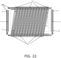
- FIGS. 20 - 22 are simplified illustrations of partially overlapping right-leaning light beams in an optical touchscreen, in accordance with an embodiment of the present invention.
- FIGS. 23 and 24 are simplified illustrations of the number of overlapping light beams provided for touch detection in different portions of a touchscreen that features the beams of FIGS. 14 - 22 , in accordance with an embodiment of the present invention
- FIGS. 25 - 27 are simplified illustrations of partially overlapping far left-leaning light beams in an optical touchscreen, in accordance with an embodiment of the present invention.
- FIGS. 28 and 29 are simplified illustrations of partially overlapping far right-leaning light beams in an optical touchscreen, in accordance with an embodiment of the present invention.
- FIGS. 30 and 31 are simplified illustrations of the number of overlapping light beams provided for touch detection in different portions of a touchscreen, featuring the beams of FIGS. 4 , 14 , 15 and 25 - 29 , in accordance with an embodiment of the present invention
- FIG. 32 is a simplified illustration of an optical touchscreen having different optics for outer and inner beams crossing the screen, in accordance with an embodiment of the present invention
- FIG. 33 A is a map showing different screen sections in an optical touchscreen, the sections having different numbers of overlapping detection channels, in accordance with an embodiment of the present invention
- FIG. 33 B illustrates the different screen sections of FIG. 33 A using text and arrows, in accordance with an embodiment of the present invention.
- FIG. 34 is a simplified illustration of the number of overlapping light beams provided for touch detection in different portions of a touchscreen for a touchscreen whose lenses are configured to split each emitter beam into two diverging beams, not three, in accordance with an embodiment of the present invention.
- FIG. 1 good gradients good gradients no gradients good signal levels intermediate signal low signal levels levels few components few components intermediate number of components few channels intermediate no. many channels channels bad angles for ghost excellent angles for excellent angles for touch suppression ghost touch ghost touch suppression suppression
- FIG. 4 is a simplified illustration of the principles of calculating a touch location based on optical signals, in the optical touchscreen of FIG. 1 , according to the present invention.
- FIG. 4 illustrates signal gradients in a touchscreen embodiment.
- Emitter 109 projects vertical light beam 409 across detection area 900 , detected by neighboring detectors 221 and 222 . Specifically, beam portion 475 is detected by detector 222 and beam portion 476 is detected by detector 221 .
- Beam portion 475 is shown as a parallelogram that extends from the lens at emitter 109 to the lens at detector 222
- beam portion 476 is shown as a parallelogram that extends from the lens at emitter 109 to the lens at detector 221 ; the dashed lines in beam portions 475 and 476 indicate the center of each beam portion.
- Lenses 301 shape beam 409 such that maximum intensity is along the center of the beam, and the intensity gradient is reduced toward the edges of the beam, as represented by detections 709 and 708 .
- Lenses 303 are similar to lenses 301 and collect the incoming light onto the detectors.
- the location of the object along the width of beam 409 is determined by comparing the detections at detectors 221 and 222 : if the detections are equal, the object is along the beam's central axis, and if the detections are unequal, their ratio indicates how far the object is shifted to one side of the beam's center.
- FIG. 4 also shows detector 219 receiving light from two emitters 111 and 112 , specifically, portion 477 of the beam from emitter 111 and portion 478 of the beam from emitter 112 arrive at detector 219 .
- the system determines where along the width of the overlap an object is positioned by comparing the detections of emitter-detector pair 111 - 219 with the detections of emitter-detector pair 112 - 219 .
- FIG. 4 shows vertical beams 417 - 419 from emitters 117 - 119 to detectors 211 - 214 . Overlapping detected portions 479 of these beams illustrate that an object placed in detection area 900 will be detected by at least two emitter-detector pairs, i.e., ⁇ (e,d), (e,d+1) ⁇ or ⁇ (e,d), (e+1,d) ⁇ , where e and e+1 are two neighboring emitters and d and d+1 are two neighboring detectors.
- the overlapping detections and the shaped light beams provide signal gradients that enable precise calculations of locations of objects touching the screen, or otherwise entering the plane of these light beams, by comparing the magnitude of detections of a single object by several emitter-detector pairs.
- One method of comparing these detections is by interpolation.
- the synchronized activation of emitter-detector pairs is controlled by processor 903 .
- Processor 903 also stores detector outputs and calculates a location of a detected object based on those outputs.
- FIG. 4 shows that the emitter lenses along two edges of detection area 900 are shift-aligned with the detector lenses along the opposite edges of detection area 900 , and the beam from each emitter detected by two opposite detectors can be expressed as being detected by detectors that are offset+/ ⁇ 0.5 lens pitch from opposite the emitter.
- light from each emitter is split into several beams detected by additional pairs of detectors to provide additional detection channels and more angles for ghost touch suppression.
- a first additional beam is directed towards detectors, along the opposite edge of the detection area, that are offset 1.5 and 2.5 lens pitches from opposite the emitter
- a second additional beam is directed towards detectors, along the opposite edge of the detection area, that are offset ⁇ 1.5 and ⁇ 2.5 lens pitches from opposite the emitter.
- different additional beams are used to provide a wider range of angles for ghost touch suppression; namely, a first additional beam is directed towards neighboring detectors that are offset 3.5 and 4.5 lens pitches from opposite the emitter, and a second additional beam is directed towards detectors that are offset ⁇ 3.5 and ⁇ 4.5 lens pitches from opposite the emitter.
- These additional beams are illustrated in FIGS. 25 - 29 .
- six sets of detection channels are provided, as illustrated in FIGS. 30 and 31 .
- Still other embodiments of the invention provide additional beams with larger emitter-detector offsets, as illustrated in FIGS. 25 - 29 , but provide additional beams with smaller emitter-detector offsets near the edges of the detection area, as illustrated in FIGS. 32 and 33 .
- FIG. 5 is a simplified illustration of light from an emitter being split into three optical channels, in accordance with an embodiment of the present invention.
- FIG. 5 illustrates splitting each emitter beam into three separate, diverging beams 484 - 486 , each separate beam being shaped with a gradient as described hereinabove with respect to FIG. 4 , such that the highest intensity is along the center of each of separate beam, and the light intensity is reduced from the center of the beam outward.
- These split, shaped beams are formed by lenses 309 , and similar lenses 311 are provided at the detectors for directing beams in each of the three directions onto each detector.
- Each of beams 484 - 486 arrives at two detectors.
- beam 484 arrives at detectors 214 and 215 ; beam 485 arrives at detectors 212 and 213 ; and beam 486 arrives at detectors 210 and 211 .
- the minimum angle between beams 484 and 485 , and between beams 485 and 486 is
- ⁇ min tan - 1 ⁇ ( 2 ⁇ p L ) where p is the pitch between neighboring components and L is the distance between the row of emitters and the opposite row of detectors.
- FIG. 5 shows each beam split into three separate, shaped beams
- each beam is split into only two separate, shaped beams, providing a greater amount of light for each separate beam.
- FIG. 6 illustrating light from emitter 118 being split into two separate beams 484 and 485 , each separate beam being shaped with a gradient as described hereinabove with respect to FIGS. 4 and 5 , such that the highest intensity is along the center of each separate beam, and the light intensity is reduced from the center of the beam outward.
- These split, shaped beams are formed by lenses 309 , and similar lenses 311 are provided at the detectors for directing beams in each of the two directions onto the detectors.
- Each of beams 484 and 485 arrives at two detectors. Specifically, beam 484 arrives at detectors 213 and 214 , and beam 485 arrives at detectors 211 and 212 . As such, the minimum angle between beams 484 and 485 , is
- ⁇ min tan - 1 ⁇ ( 2 ⁇ p L ) where p is the pitch between neighboring components and L is the distance between the row of emitters and the opposite row of detectors.
- Beams 484 and 485 are both projected by emitter 118 .
- Lenses 309 split and shape these two beams and direct them at detectors 211 - 214 , via lenses 311 .
- the detections at detectors 211 - 214 are indicated by sloping curves 711 - 714 .
- the maximum intensity for each beam is along its center, indicated by the maximum of each curve 711 - 714 being near the beam center and declining outward.
- FIG. 7 is a simplified illustration of distinguishing an actual touch from a ghost touch, in accordance with embodiments of the present invention.
- FIG. 7 shows two touches in detection area 904 and illustrates that, in a system with two diverging beams for each emitter as illustrated in FIG. 6 , the locations of the four candidate touch points indicated by blocked left-sloping beams 484 of FIG. 6 are slightly different than the four candidate touch points indicated by the blocked right-sloping beams 485 of FIG. 6 .
- Arrows 931 indicate the directions of the right-sloping vertical and horizontal beams
- arrows 932 indicate the directions of the left-sloping vertical and horizontal beams.
- the right-sloping beams indicate possible touch locations 910 , 911 , 912 ′ and 913 ′
- the left-sloping beams indicate possible touch locations 910 , 911 , 912 ′′ and 913 ′′.
- locations 910 and 911 at which actual objects are present are identical for both sets of beams, whereas the ghost locations 912 and 913 are not the same. Accordingly, by comparing the touch locations indicated by the different sets of beams, it is determined that locations that are identical for the different sets of beams are actual touch locations, and locations that are not identical for the different sets of beams are not touch locations.
- splitting the light from each emitter into two or three beams provides different angled beams that resolve many ghost touch situations that the touchscreen of FIG. 1 cannot similarly resolve.
- the split beams cover most of the display area with many different overlapping beams, providing greater resolution and precision for calculating touch locations.
- FIG. 8 is a simplified illustration of five different beams that may be created by a lens, in accordance with embodiments of the present invention.
- FIG. 8 shows five different beams 487 - 491 that may be created from emitter 118 by a lens.
- each of the five beams is shaped to have maximum intensity along the center with the intensity decreasing further from the central line. This beam shape enables identifying where within the width of the beam an object is located based on the amount of light it blocks.
- Each beam is directed toward a pair of detectors at the opposite edge of the detection area.
- each lens creates three of these five beams.
- the lenses farther from the corners of detection area 904 generate the central beam 489 and the two outer beams 487 and 491 , in order to provide beams separated by large angles, whereas lenses closer to the corners of the detection area are configured to generate the three inner beams 488 - 490 , as an outer beam 487 or 491 would be directed outside detection area 904 and would not reach a detector on the opposite edge.
- FIGS. 9 - 12 are illustrations of lenses used in an optical sensor, in accordance with an embodiment of the present invention.
- FIG. 9 shows a touchscreen having detection area 904 surrounded by lens structures 309 - 312 , and cross-sections thereof.
- FIG. 10 shows lens structure 309 of the touchscreen in FIG. 9 .
- This lens structure is mounted above a series of light emitters, and it splits the light from each emitter into three separate beams.
- FIG. 10 shows focusing lenses 324 and 325 , and lenses 327 and 328 that split the light into separate beams.
- FIG. 11 shows one of focusing lenses 325 and the associated portion of lens 327 , having a repeating three-facet pattern indicated by three arrows that split the light into three separate beams.
- lens 327 has a repeating sawtooth pattern of facets in two directions to create two diverging beams.
- FIG. 12 shows a section of lens structure 309 near the corner of the touch detection area.
- This section includes focusing lens 324 and associated lens 328 for splitting the light. Because this lens is near a corner of the detection area, lens 328 is configured to direct the light so that the rightmost beam arrives at a detector on the opposite edge of the detection area, and in some embodiments this section splits the light into fewer beams than the other sections. In certain embodiments, this section of lenses is smaller than the others and is thus configured to create more concentrated beams of light than the other sections because an edge of the screen is covered by fewer overlapping beams than other screen sections.
- FIG. 13 is a simplified illustration of an optical touchscreen detection area, in accordance with an embodiment of the present invention.
- FIG. 13 shows a frame of lenses 308 - 311 surrounding detection area 904 , in accordance with an embodiment of the present invention.
- Each lens in lens array 308 directs beams from a respective one of emitters 100 - 107 across detection area 904 .
- Each lens in lens array 310 directs incoming light onto a respective one of detectors 200 - 208 .
- the number of detectors 200 - 208 is greater than the number of opposite emitters 100 - 107 , as the emitters and detectors are shift-aligned.
- lens array 310 which features seven full-lenses and two half-lenses at either end of array 310
- lens array 308 features eight full lenses.
- Each lens in lens array 309 directs light beams from a respective one of emitters 108 - 121 across detection area 904 .
- Each lens, or half-lens at either end, in lens array 311 directs incoming light onto a respective one of detectors 209 - 223 .
- the number of detectors 209 - 223 is greater than the number of opposite emitters 108 - 121 , as the emitters and detectors are shift-aligned.
- lens array 311 which features thirteen full-lenses and two half-lenses at either end of array 311
- lens array 309 features fourteen full lenses.
- light from each emitter is split into multiple separate shaped beams, and each beam arrives at two neighboring detectors along the opposite edge of detection area 904 .
- An emitter-detector pair refers to a portion of the light beam from one emitter that arrives at one opposite detector. The following figures illustrate these portions to indicate the various emitter-detector pairs providing detection information in accordance with embodiments of the present invention.
- FIGS. 14 - 16 are simplified illustrations of partially overlapping central light beams in an optical touchscreen, in accordance with an embodiment of the present invention.
- FIG. 14 shows a first set of beam portions 500 - 513 , namely, the left-hand portion of the central beam from each emitter. These beam portions provide a first set of emitter-detector detection channels.
- FIG. 15 shows a second set of beam portions 514 - 527 , namely, the right-hand portion of the central beam from each emitter. These beam portions provide a second set of emitter-detector detection channels.
- FIG. 16 shows coverage of detection area 904 by beam portions 500 - 527 shown in FIGS. 14 and 15 .
- FIG. 16 indicates that most of detection area 904 is covered by two beam portions; i.e., two detection channels, except for two narrow triangular sections at the outer edges of detection area 904 , which are only covered by one detection channel.
- a similar coverage map exists for the horizontal beams traveling from emitters 100 - 107 to detectors 200 - 208 .
- FIGS. 17 - 19 are simplified illustrations of partially overlapping left-leaning light beams in an optical touchscreen, in accordance with an embodiment of the present invention.
- FIG. 17 shows a third set of beam portions 528 - 539 , namely, the left-hand portion of the left-leaning beam from each emitter. These beam portions provide a third set of emitter-detector detection channels.
- FIG. 18 shows a fourth set of beam portions 540 - 551 , namely, the right-hand portion of the left-leaning beam from each emitter. These beam portions provide a fourth set of emitter-detector detection channels.
- FIG. 19 shows additional coverage of detection area 904 by the left-leaning beams; i.e., beam portions 528 - 551 shown in FIGS. 17 and 18 .
- FIG. 19 indicates that most of detection area 904 is covered by two beam portions; i.e., two detection channels, except for a first narrow triangular section along the outer left edge of left-leaning beam 528 , and a wider triangular section at the outer right edge of left-leaning beam 551 , which are only covered by one detection channel.
- FIG. 19 also illustrates two triangular sections at the outer edges of detection area 904 that are not covered by these left-leaning beams.
- a similar coverage map exists for the horizontal beams traveling from emitters 100 - 107 to detectors 200 - 208 .
- FIG. 19 indicates series 921 of emitters and series 920 of detectors that are active in providing the illustrated detection channels 528 - 551 .
- FIGS. 20 - 22 are simplified illustrations of partially overlapping right-leaning light beams in an optical touchscreen, in accordance with an embodiment of the present invention.
- FIG. 20 shows a fifth set of beam portions 563 - 574 ; namely, the left-hand portion of the right-leaning beam from each emitter. These beam portions provide a fifth set of emitter-detector detection channels.
- FIG. 21 shows a sixth set of beam portions 575 - 586 , namely, the right-hand portion of the right-leaning beam from each emitter. These beam portions provide a sixth set of emitter-detector detection channels.
- FIG. 22 shows additional coverage of detection area 904 by the right-leaning beams; i.e., beam portions 563 - 586 shown in FIGS. 20 and 21 .
- FIG. 22 indicates that most of detection area 904 is covered by two beam portions; i.e., two detection channels, except for a first narrow triangular section along the outer right edge of right-leaning beam 586 , and a wider triangular section at the outer left edge of right-leaning beam 563 , which are only covered by one detection channel.
- FIG. 22 also illustrates two triangular sections at the outer edges of detection area 904 that are not covered by these right-leaning beams.
- a similar coverage map exists for the horizontal beams traveling from emitters 100 - 107 to detectors 200 - 208 .
- FIG. 22 indicates series 923 of emitters and series 922 of detectors that are active in providing the illustrated detection channels 563 - 586 .
- FIGS. 23 and 24 are simplified illustrations of the number of overlapping light beams provided for touch detection in different portions of a touchscreen that features the beams of FIGS. 14 - 22 , in accordance with an embodiment of the present invention.
- FIG. 23 shows coverage of detection area 904 when all six sets of detection channels discussed hereinabove with reference to FIGS. 14 - 22 are combined.
- the central portion of detection area 904 is covered by multiple detection signals from all six sets of detection beams—the central, left-leaning and right-leaning beams.
- FIG. 23 indicates areas near the edges of detection area 904 that are covered by only three or four sets of detection signals, and areas covered by only one or two detection signals.
- FIG. 24 indicates the number of detection channels covering different portions of detection area 904 , in the embodiment illustrated in FIG. 23 .
- the number of detection channels varies between 1-6.
- a similar map of detection channels applies to the horizontal beams, from emitters 100 - 107 to detectors 200 - 208 .
- FIGS. 25 - 27 are simplified illustrations of partially overlapping far left-leaning light beams in an optical touchscreen, in accordance with an embodiment of the present invention.
- FIG. 25 illustrates detection channels between each emitter and a respective detector that is offset 4.5 lens pitches from opposite the emitter;
- FIG. 26 illustrates detection channels between each emitter and a respective detector that is offset 3.5 lens pitches from opposite the emitter; and FIG. 27 illustrates the combined area covered by these two detection channels.
- FIG. 27 indicates series 925 of emitters and series 924 of detectors that are active in providing the illustrated detection channels 600 - 619 .
- FIGS. 28 and 29 are simplified illustrations of partially overlapping far right-leaning light beams in an optical touchscreen, in accordance with an embodiment of the present invention.
- FIG. 28 illustrates detection channels between each emitter and a respective detector that is offset ⁇ 3.5 lens pitches from opposite the emitter;
- FIG. 29 illustrates detection channels between each emitter and a respective detector that is offset ⁇ 4.5 lens pitches from opposite the emitter.
- FIGS. 30 and 31 are simplified illustrations of the number of overlapping light beams provided for touch detection in different portions of a touchscreen, featuring the beams of FIGS. 4 , 14 , 15 and 25 - 29 , in accordance with an embodiment of the present invention.
- FIGS. 30 and 31 show the number of channels covering different portions of the detection area that utilize the beams illustrated in FIGS. 4 , 14 , 15 and 25 - 29 .
- FIGS. 30 and 31 show that the outer portions of the detection area have fewer detection channels than the central portion of the detection area.
- FIGS. 30 and 31 indicate series 925 , 927 of emitters and series 924 , 926 of detectors that are active in providing the illustrated detection channels 600 - 619 .
- FIGS. 32 and 33 are simplified illustrations of optical touchscreens having different optics for outer and inner beams crossing the screen, in accordance with an embodiment of the present invention.
- FIG. 32 shows detection channels provided along the outer edges of a detection area by beams similar to beams 484 and 486 in FIG. 5 . Adding these beams to the system illustrated in FIGS. 30 and 31 , provides the outer edge-related portions of the detection area with additional detection channels.
- FIGS. 33 A and 33 B are two views of detection channel coverage in the system of FIGS. 30 and 31 when the additional beams and channels shown in FIG. 32 are provided along the edges of the detection area.
- FIG. 33 A is color-coded
- FIG. 33 B uses text and arrows to indicate the number of detection channels for each section of the touchscreen.
- FIGS. 33 A and 33 B show that portions of the detection area have up to nine detection channels. Additional beams with even larger emitter-detector offsets can be added to the optical sensor by modifying the lenses and the emitter-detector activation sequence, and such systems are also within the scope of the present invention.
- FIG. 34 is a simplified illustration of the number of overlapping light beams provided for touch detection in different portions of a touchscreen for a touchscreen whose lenses are configured to split each emitter beam into two diverging beams, not three, in accordance with an embodiment of the present invention.
- FIG. 34 shows the number of beams, or detection channels, that cover each part of a touchscreen when light from each emitter is split into four beams, namely, the two beams 484 and 485 of FIG. 6 and one beam to the left of beam 484 and another beam to the right of beam 485 .
- the edge portions of the touchscreen have fewer beams, or detection channels, than the center of the screen.
- a smaller portion of light from the emitters near the corners is used for touch detection as fewer channels can be used along the screen edges. Therefore, in certain embodiments of the invention, the light channels traversing the screen along the screen edges are shaped to be wider and therefore contain more signal strength than the channels in the middle of the screen. This requires that the lenses near the screen corners are longer than the other lenses, and the light channel is spread across a larger segment of the edge near the corner than the other light channels.
- each beam is assigned coordinates based on its center line and a weighted sum of all of these coordinates is calculated according to the amount that the signal is blocked.
- coordinates are also assigned to the edge beams and they are added to the weighted average, in the same way as the other beams.
- the distance between the central line of a beam near an edge of the screen and its neighboring beam is greater than the distance between the central lines of other neighboring beams.
Abstract
Description
| TABLE I |
| Features of touchscreen systems in FIGS. 1 and 2 |
| FIG. 1 | FIG. 2 |
| good gradients | no gradients |
| good signal levels | low signal levels |
| few components | intermediate number of components |
| few channels | many channels |
| bad angles for ghost touch | excellent angles for ghost touch |
| suppression | suppression |
| TABLE II |
| Elements of Figures |
| Type of element | Numbering range | FIGS. |
| light emitters | 100-199 | 1, 2, 4-6, 8, 13-32, 34 |
| light detectors | 200-299 | 1, 2, 4-6, 13-32, 34 |
| lenses | 300-399 | 1, 2, 4-6, 9-32, 34 |
| light beams | 400-699 | 1, 2, 4-6, 8, 14, 15, 17-23, 25-30 |
| light detection | 700-799 | 3-6 |
| other items | 900-999 | 1-5, 7-9, 13-32, 34 |
| TABLE III |
| Features of the Present Invention |
| FIG. 1 | Present invention | FIG. 2 |
| good gradients | good gradients | no gradients |
| good signal levels | intermediate signal | low signal levels |
| levels | ||
| few components | few components | intermediate number |
| of components | ||
| few channels | intermediate no. | many channels |
| channels | ||
| bad angles for ghost | excellent angles for | excellent angles for |
| touch suppression | ghost touch | ghost touch |
| suppression | suppression | |
where p is the pitch between neighboring components and L is the distance between the row of emitters and the opposite row of detectors.
where p is the pitch between neighboring components and L is the distance between the row of emitters and the opposite row of detectors.
Claims (14)
Priority Applications (2)
| Application Number | Priority Date | Filing Date | Title |
|---|---|---|---|
| US17/487,195 US11669210B2 (en) | 2020-09-30 | 2021-09-28 | Optical touch sensor |
| US18/327,419 US20230325035A1 (en) | 2020-09-30 | 2023-06-01 | Optical touch sensor |
Applications Claiming Priority (2)
| Application Number | Priority Date | Filing Date | Title |
|---|---|---|---|
| US202063085838P | 2020-09-30 | 2020-09-30 | |
| US17/487,195 US11669210B2 (en) | 2020-09-30 | 2021-09-28 | Optical touch sensor |
Related Child Applications (1)
| Application Number | Title | Priority Date | Filing Date |
|---|---|---|---|
| US18/327,419 Continuation US20230325035A1 (en) | 2020-09-30 | 2023-06-01 | Optical touch sensor |
Publications (2)
| Publication Number | Publication Date |
|---|---|
| US20220100313A1 US20220100313A1 (en) | 2022-03-31 |
| US11669210B2 true US11669210B2 (en) | 2023-06-06 |
Family
ID=80821219
Family Applications (2)
| Application Number | Title | Priority Date | Filing Date |
|---|---|---|---|
| US17/487,195 Active US11669210B2 (en) | 2020-09-30 | 2021-09-28 | Optical touch sensor |
| US18/327,419 Pending US20230325035A1 (en) | 2020-09-30 | 2023-06-01 | Optical touch sensor |
Family Applications After (1)
| Application Number | Title | Priority Date | Filing Date |
|---|---|---|---|
| US18/327,419 Pending US20230325035A1 (en) | 2020-09-30 | 2023-06-01 | Optical touch sensor |
Country Status (6)
| Country | Link |
|---|---|
| US (2) | US11669210B2 (en) |
| EP (1) | EP4222586A1 (en) |
| JP (1) | JP2023544332A (en) |
| KR (1) | KR20230074269A (en) |
| CN (1) | CN116420125A (en) |
| WO (1) | WO2022072331A1 (en) |
Citations (387)
| Publication number | Priority date | Publication date | Assignee | Title |
|---|---|---|---|---|
| US4243879A (en) | 1978-04-24 | 1981-01-06 | Carroll Manufacturing Corporation | Touch panel with ambient light sampling |
| US4267443A (en) | 1978-04-24 | 1981-05-12 | Carroll Manufacturing Corporation | Photoelectric input apparatus |
| US4301447A (en) | 1979-12-12 | 1981-11-17 | Sperry Corporation | Scan control for light beam position indicator |
| US4518249A (en) | 1982-11-30 | 1985-05-21 | Minolta Camera Kabushiki Kaisha | Slit illumination system for copying machine and the like |
| US4550250A (en) | 1983-11-14 | 1985-10-29 | Hei, Inc. | Cordless digital graphics input device |
| WO1986000447A1 (en) | 1984-06-18 | 1986-01-16 | Amp Incorporated | Touch input device having digital ambient light sampling |
| WO1986000446A1 (en) | 1984-06-18 | 1986-01-16 | Amp Incorporated | Touch input device |
| US4588258A (en) | 1983-09-12 | 1986-05-13 | Minnesota Mining And Manufacturing Company | Cube-corner retroreflective articles having wide angularity in multiple viewing planes |
| US4641426A (en) | 1985-06-21 | 1987-02-10 | Associated Enterprises, Inc. | Surface mount compatible connector system with mechanical integrity |
| US4645920A (en) | 1984-10-31 | 1987-02-24 | Carroll Touch, Inc. | Early fault detection in an opto-matrix touch input device |
| US4672364A (en) | 1984-06-18 | 1987-06-09 | Carroll Touch Inc | Touch input device having power profiling |
| US4703316A (en) | 1984-10-18 | 1987-10-27 | Tektronix, Inc. | Touch panel input apparatus |
| US4710760A (en) | 1985-03-07 | 1987-12-01 | American Telephone And Telegraph Company, At&T Information Systems Inc. | Photoelastic touch-sensitive screen |
| US4737626A (en) | 1985-02-15 | 1988-04-12 | Alps Electric Co., Ltd. | Photoelectric touch panel having reflector and transparent photoconductive plate |
| US4737631A (en) | 1985-05-17 | 1988-04-12 | Alps Electric Co., Ltd. | Filter of photoelectric touch panel with integral spherical protrusion lens |
| US4761637A (en) | 1984-06-18 | 1988-08-02 | Carroll Touch Inc. | Touch input device |
| US4782328A (en) | 1986-10-02 | 1988-11-01 | Product Development Services, Incorporated | Ambient-light-responsive touch screen data input method and system |
| US4790028A (en) | 1986-09-12 | 1988-12-06 | Westinghouse Electric Corp. | Method and apparatus for generating variably scaled displays |
| US4847606A (en) | 1987-08-25 | 1989-07-11 | Oak Industries Inc. | Control and display system |
| EP0330767A1 (en) | 1987-01-10 | 1989-09-06 | Pioneer Electronic Corporation | Touch panel control device with touch time and finger direction discrimination |
| US4868912A (en) | 1986-11-26 | 1989-09-19 | Digital Electronics | Infrared touch panel |
| US4880969A (en) | 1986-04-30 | 1989-11-14 | Litton Systems, Inc. | Optical touch panel with heat sink |
| US4905174A (en) | 1987-09-07 | 1990-02-27 | Alps Electric Co., Ltd. | Optical coordinate input apparatus |
| US4928094A (en) | 1988-01-25 | 1990-05-22 | The Boeing Company | Battery-operated data collection apparatus having an infrared touch screen data entry device |
| US5003505A (en) | 1984-05-07 | 1991-03-26 | Hewlett-Packard Company | Touchscreen/keyboard scanner |
| US5016008A (en) | 1987-05-25 | 1991-05-14 | Sextant Avionique | Device for detecting the position of a control member on a touch-sensitive pad |
| US5036187A (en) | 1989-05-08 | 1991-07-30 | Dowa Mining Co., Ltd. | Photodetecting circuit with compensated integration signal |
| JPH03216719A (en) | 1990-01-22 | 1991-09-24 | Fujitsu Ltd | Position instruction device |
| US5053758A (en) | 1988-02-01 | 1991-10-01 | Sperry Marine Inc. | Touchscreen control panel with sliding touch control |
| US5119079A (en) | 1990-09-17 | 1992-06-02 | Xerox Corporation | Touch screen user interface with expanding touch locations for a reprographic machine |
| US5162783A (en) | 1990-07-23 | 1992-11-10 | Akzo N.V. | Infrared touch screen device for a video monitor |
| JPH04322204A (en) | 1991-04-23 | 1992-11-12 | Sumitomo Chem Co Ltd | Plane lighting device |
| EP0513694A2 (en) | 1991-05-09 | 1992-11-19 | Sony Corporation | Apparatus and method for inputting data |
| US5179369A (en) | 1989-12-06 | 1993-01-12 | Dale Electronics, Inc. | Touch panel and method for controlling same |
| US5194863A (en) | 1989-04-10 | 1993-03-16 | International Business Machines Corporation | Touch panel display |
| US5196835A (en) | 1988-09-30 | 1993-03-23 | International Business Machines Corporation | Laser touch panel reflective surface aberration cancelling |
| US5220409A (en) | 1988-12-19 | 1993-06-15 | Amp Incorporated | Light beam detection utilizing hologram |
| JPH05173699A (en) | 1991-12-20 | 1993-07-13 | Fujitsu Ltd | Coordinate input device |
| US5283558A (en) | 1989-10-16 | 1994-02-01 | Chan James K | Low-cost devices for touch control |
| JPH0639621U (en) | 1992-10-30 | 1994-05-27 | 日本精機株式会社 | Vehicle switch device |
| EP0601651A1 (en) | 1992-12-10 | 1994-06-15 | Koninklijke Philips Electronics N.V. | Optical touch tablet based on sector cross bearing |
| EP0618528A1 (en) | 1993-04-01 | 1994-10-05 | International Business Machines Corporation | Dynamic touchscreen button adjustment mechanism |
| US5406307A (en) | 1989-12-05 | 1995-04-11 | Sony Corporation | Data processing apparatus having simplified icon display |
| US5414413A (en) | 1988-06-14 | 1995-05-09 | Sony Corporation | Touch panel apparatus |
| US5422494A (en) | 1992-10-16 | 1995-06-06 | The Scott Fetzer Company | Barrier transmission apparatus |
| US5463725A (en) | 1992-12-31 | 1995-10-31 | International Business Machines Corp. | Data processing system graphical user interface which emulates printed material |
| EP0703525A1 (en) | 1994-09-22 | 1996-03-27 | Aisin Aw Co., Ltd. | Touch display type information input system |
| US5559727A (en) | 1994-02-24 | 1996-09-24 | Quad Systems Corporation | Apparatus and method for determining the position of a component prior to placement |
| US5579035A (en) | 1991-07-05 | 1996-11-26 | Technomarket, L.P. | Liquid crystal display module |
| US5577733A (en) | 1994-04-08 | 1996-11-26 | Downing; Dennis L. | Targeting system |
| US5603053A (en) | 1993-05-10 | 1997-02-11 | Apple Computer, Inc. | System for entering data into an active application currently running in the foreground by selecting an input icon in a palette representing input utility |
| US5605406A (en) | 1992-08-24 | 1997-02-25 | Bowen; James H. | Computer input devices with light activated switches and light emitter protection |
| US5612719A (en) | 1992-12-03 | 1997-03-18 | Apple Computer, Inc. | Gesture sensitive buttons for graphical user interfaces |
| US5618232A (en) | 1995-03-23 | 1997-04-08 | Martin; John R. | Dual mode gaming device methods and systems |
| US5729250A (en) | 1995-05-08 | 1998-03-17 | International Business Machines Corporation | Front cover assembly for a touch sensitive device |
| US5748185A (en) | 1996-07-03 | 1998-05-05 | Stratos Product Development Group | Touchpad with scroll and pan regions |
| JPH10269012A (en) | 1997-03-28 | 1998-10-09 | Yazaki Corp | Touch panel controller and information display device using the same |
| US5825352A (en) | 1996-01-04 | 1998-10-20 | Logitech, Inc. | Multiple fingers contact sensing method for emulating mouse buttons and mouse operations on a touch sensor pad |
| US5838308A (en) | 1991-04-17 | 1998-11-17 | U.S. Philips Corporation | Optical touch input device |
| EP0884691A2 (en) | 1997-06-13 | 1998-12-16 | Kabushiki Kaisha Tokai-Rika-Denki-Seisakusho | Touch operation signal output device |
| US5880462A (en) | 1995-08-24 | 1999-03-09 | Hsia; Chih-Yu | Keying apparatus with thumb gap |
| US5880743A (en) | 1995-01-24 | 1999-03-09 | Xerox Corporation | Apparatus and method for implementing visual animation illustrating results of interactive editing operations |
| US5886697A (en) | 1993-05-24 | 1999-03-23 | Sun Microsystems, Inc. | Method and apparatus for improved graphical user interface having anthropomorphic characters |
| US5889236A (en) | 1992-06-08 | 1999-03-30 | Synaptics Incorporated | Pressure sensitive scrollbar feature |
| US5900863A (en) | 1995-03-16 | 1999-05-04 | Kabushiki Kaisha Toshiba | Method and apparatus for controlling computer without touching input device |
| US5900875A (en) | 1997-01-29 | 1999-05-04 | 3Com Corporation | Method and apparatus for interacting with a portable computer system |
| US5914709A (en) | 1997-03-14 | 1999-06-22 | Poa Sana, Llc | User input device for a computer system |
| US5936615A (en) | 1996-09-12 | 1999-08-10 | Digital Equipment Corporation | Image-based touchscreen |
| US5943043A (en) | 1995-11-09 | 1999-08-24 | International Business Machines Corporation | Touch panel "double-touch" input method and detection apparatus |
| US5943044A (en) | 1996-08-05 | 1999-08-24 | Interlink Electronics | Force sensing semiconductive touchpad |
| JPH11232024A (en) | 1998-02-13 | 1999-08-27 | Alpine Electron Inc | Optical position detector |
| US5946134A (en) | 1993-10-20 | 1999-08-31 | Minnesota Mining & Manufacturing Company | Raised structure retroreflective article |
| US5956030A (en) | 1993-06-11 | 1999-09-21 | Apple Computer, Inc. | Computer system with graphical user interface including windows having an identifier within a control region on the display |
| US6010061A (en) | 1998-03-27 | 2000-01-04 | Micron Custom Manufacturing Services Inc. | Reflow soldering method |
| US6023265A (en) | 1996-08-28 | 2000-02-08 | Lg Industrial Systems Co., Ltd. | Touched state recognition apparatus for matrix type touch panel and a control method thereof |
| US6031989A (en) | 1997-02-27 | 2000-02-29 | Microsoft Corporation | Method of formatting and displaying nested documents |
| US6035180A (en) | 1997-10-07 | 2000-03-07 | Ericsson Inc. | Communication module having selectively programmable exterior surface |
| US6052279A (en) | 1996-12-05 | 2000-04-18 | Intermec Ip Corp. | Customizable hand-held computer |
| US6073036A (en) | 1997-04-28 | 2000-06-06 | Nokia Mobile Phones Limited | Mobile station with touch input having automatic symbol magnification function |
| US6085204A (en) | 1996-09-27 | 2000-07-04 | Sharp Kabushiki Kaisha | Electronic dictionary and information displaying method, incorporating rotating highlight styles |
| US6091405A (en) | 1992-06-30 | 2000-07-18 | International Business Machines Corporation | Input device |
| EP1059603A2 (en) | 1999-06-07 | 2000-12-13 | Kabushiki Kaisha Tokai-Rika-Denki-Seisakusho | Touch position determining method |
| WO2001002949A1 (en) | 1999-07-06 | 2001-01-11 | Chuang Li | Methods and apparatus for controlling a portable electronic device using a touchpad |
| WO2001040922A2 (en) | 1999-12-02 | 2001-06-07 | Elo Touchsystems, Inc. | Apparatus and method to improve resolution of infrared touch systems |
| US20010002694A1 (en) | 1998-08-18 | 2001-06-07 | Fujitsu Limited | Optical scanning-type touch panel |
| US6246395B1 (en) | 1998-12-17 | 2001-06-12 | Hewlett-Packard Company | Palm pressure rejection method and apparatus for touchscreens |
| US6259436B1 (en) | 1998-12-22 | 2001-07-10 | Ericsson Inc. | Apparatus and method for determining selection of touchable items on a computer touchscreen by an imprecise touch |
| US6292179B1 (en) | 1998-05-12 | 2001-09-18 | Samsung Electronics Co., Ltd. | Software keyboard system using trace of stylus on a touch screen and method for recognizing key code using the same |
| US20010022579A1 (en) | 2000-03-16 | 2001-09-20 | Ricoh Company, Ltd. | Apparatus for inputting coordinates |
| US20010026268A1 (en) | 2000-03-31 | 2001-10-04 | Ricoh Company, Ltd. | Coordiante input and detection device and information display and input apparatus |
| US20010028344A1 (en) | 1998-11-20 | 2001-10-11 | Fujitsu Limited | Optical scanning-type touch panel |
| US20010030641A1 (en) | 2000-03-14 | 2001-10-18 | Alps Electric Co., Ltd. | Input control system with the ability of setting arbitrary switch functions of the switch input section |
| US20010043189A1 (en) | 1998-06-12 | 2001-11-22 | Michel A. Brisebois | Active edge user interface |
| US6323846B1 (en) | 1998-01-26 | 2001-11-27 | University Of Delaware | Method and apparatus for integrating manual input |
| US6333735B1 (en) | 1999-03-16 | 2001-12-25 | International Business Machines Corporation | Method and apparatus for mouse positioning device based on infrared light sources and detectors |
| US20010055006A1 (en) | 1999-02-24 | 2001-12-27 | Fujitsu Limited | Optical scanning-type touch panel |
| US20020002326A1 (en) | 1998-08-18 | 2002-01-03 | Causey James D. | Handheld personal data assistant (PDA) with a medical device and method of using the same |
| US6337873B1 (en) | 1998-01-09 | 2002-01-08 | Jenoptik Aktiengesellschaft | Optical arrangement for balancing the beam of one or more high power diode lasers arranged one above another |
| US6340979B1 (en) | 1997-12-04 | 2002-01-22 | Nortel Networks Limited | Contextual gesture interface |
| US6346935B1 (en) | 1998-09-14 | 2002-02-12 | Matsushita Electric Industrial Co., Ltd. | Touch-sensitive tablet |
| US20020018824A1 (en) | 1999-03-19 | 2002-02-14 | Buazza Omar M. | Plastic lens systems, compositions, and methods |
| US20020027549A1 (en) | 2000-03-03 | 2002-03-07 | Jetway Technologies Ltd. | Multifunctional keypad on touch screen |
| US6356287B1 (en) | 1998-03-20 | 2002-03-12 | Nuvomedia, Inc. | Citation selection and routing feature for hand-held content display device |
| US6359632B1 (en) | 1997-10-24 | 2002-03-19 | Sony United Kingdom Limited | Audio processing system having user-operable controls |
| US20020033805A1 (en) | 2000-09-20 | 2002-03-21 | Susumu Fujioka | Coordinate input detection device and method for electronic blackboard |
| US6362468B1 (en) | 1999-06-10 | 2002-03-26 | Saeilo Japan, Inc. | Optical unit for detecting object and coordinate input apparatus using same |
| US20020046353A1 (en) | 2000-08-18 | 2002-04-18 | Sony Corporation | User authentication method and user authentication server |
| US20020060699A1 (en) | 2000-01-26 | 2002-05-23 | D'agostini Giovanni | Character input device based on a two-dimensional movememt sensor |
| US20020067346A1 (en) | 2000-09-22 | 2002-06-06 | Eric Mouton | Graphical user interface for devices having small tactile displays |
| US20020075244A1 (en) | 1991-04-08 | 2002-06-20 | Masayuki Tani | Video or information processing method and processing apparatus, and monitoring method and monitoring apparatus using the same |
| US20020075243A1 (en) | 2000-06-19 | 2002-06-20 | John Newton | Touch panel display system |
| US6411283B1 (en) | 1999-05-20 | 2002-06-25 | Micron Technology, Inc. | Computer touch screen adapted to facilitate selection of features at edge of screen |
| US6421042B1 (en) | 1998-06-09 | 2002-07-16 | Ricoh Company, Ltd. | Coordinate position inputting/detecting device, a method for inputting/detecting the coordinate position, and a display board system |
| US20020108693A1 (en) | 1998-07-16 | 2002-08-15 | Veligdan James T. | Light redirective display panel and a method of making a light redirective display panel |
| US20020109843A1 (en) | 2001-02-13 | 2002-08-15 | Applied Materials, Inc. | Method and system for registering fiducials employing backlighting techniques |
| US20020118177A1 (en) | 2000-05-24 | 2002-08-29 | John Newton | Protected touch panel display system |
| US6456952B1 (en) | 2000-03-29 | 2002-09-24 | Ncr Coporation | System and method for touch screen environmental calibration |
| US20020171691A1 (en) | 2001-05-18 | 2002-11-21 | Currans Kevin G. | Personal digital assistant with streaming information display |
| US20020173300A1 (en) | 2001-05-21 | 2002-11-21 | Yuri Shtivelman | Method and system for completing incomplete addressing data sent to a communication device |
| WO2002095668A1 (en) | 2001-05-22 | 2002-11-28 | Palm, Inc. | Touch display assembly |
| US20020175900A1 (en) | 2001-04-04 | 2002-11-28 | Armstrong Donald B. | Touch input system |
| US20020191029A1 (en) | 2001-05-16 | 2002-12-19 | Synaptics, Inc. | Touch screen with user interface enhancement |
| US20030002809A1 (en) | 1998-06-08 | 2003-01-02 | Jian Benjamin B. | Vertically integrated optical devices coupled to optical fibers |
| US20030013483A1 (en) | 2001-07-06 | 2003-01-16 | Ausems Michiel R. | User interface for handheld communication device |
| US20030010043A1 (en) | 2001-07-16 | 2003-01-16 | Ferragut Nelson J. | Menu-based control system for refrigerator that predicts order and replace dates for filters |
| US20030030656A1 (en) | 2001-06-12 | 2003-02-13 | Darwin Ang | Method and system for dynamic hierarchical data display |
| US6529920B1 (en) | 1999-03-05 | 2003-03-04 | Audiovelocity, Inc. | Multimedia linking device and method |
| US20030043207A1 (en) | 2001-09-06 | 2003-03-06 | Matias Duarte | Method of scrolling a display window |
| US6542191B1 (en) | 1996-04-23 | 2003-04-01 | Canon Kabushiki Kaisha | Image display apparatus, camera control apparatus and method |
| US6549217B1 (en) | 2000-03-23 | 2003-04-15 | Koninklijke Philips Electronics N.V. | System and method for computer system management using bookmarks |
| US20030076306A1 (en) | 2001-10-22 | 2003-04-24 | Zadesky Stephen Paul | Touch pad handheld device |
| WO2003038592A1 (en) | 2001-11-02 | 2003-05-08 | Magnus George Goertz | On a substrate formed or resting display arrangement |
| US20030095102A1 (en) | 2001-11-19 | 2003-05-22 | Christian Kraft | Communication terminal having a predictive character editor application |
| US6570557B1 (en) | 2001-02-10 | 2003-05-27 | Finger Works, Inc. | Multi-touch system and method for emulating modifier keys via fingertip chords |
| US20030098803A1 (en) | 2001-09-18 | 2003-05-29 | The Research Foundation Of The City University Of New York | Tactile graphic-based interactive overlay assembly and computer system for the visually impaired |
| US20030122787A1 (en) | 2001-12-28 | 2003-07-03 | Philips Electronics North America Corporation | Touch-screen image scrolling system and method |
| US6628268B1 (en) | 1999-07-30 | 2003-09-30 | Matsushita Electric Industrial Co., Ltd. | Transparent touch panel and electronic equipment using the same |
| WO2003083767A2 (en) | 2002-03-27 | 2003-10-09 | Nellcor Puritan Bennett Incorporated | Infrared touchframe system |
| US20030231308A1 (en) | 2001-11-21 | 2003-12-18 | Granger Edward M. | Refractive-diffractive spectrometer |
| US20030234346A1 (en) | 2002-06-21 | 2003-12-25 | Chi-Lei Kao | Touch panel apparatus with optical detection for location |
| US6677932B1 (en) | 2001-01-28 | 2004-01-13 | Finger Works, Inc. | System and method for recognizing touch typing under limited tactile feedback conditions |
| US20040021681A1 (en) | 2002-07-30 | 2004-02-05 | Liao Chin-Hua Arthur | Dual-touch-screen mobile computer |
| US20040021643A1 (en) | 2002-08-02 | 2004-02-05 | Takeshi Hoshino | Display unit with touch panel and information processing method |
| US6690365B2 (en) | 2001-08-29 | 2004-02-10 | Microsoft Corporation | Automatic scrolling |
| US20040046960A1 (en) | 2002-09-11 | 2004-03-11 | Wagner Mark Donald | Lens blank alignment and blocking device and method |
| US6707449B2 (en) | 2000-08-30 | 2004-03-16 | Microsoft Corporation | Manual controlled scrolling |
| US6727917B1 (en) | 2000-01-06 | 2004-04-27 | Microsoft Corporation | User interface for palm-sized computing devices and method and apparatus for displaying the same |
| US6734883B1 (en) | 2000-05-25 | 2004-05-11 | International Business Machines Corporation | Spinlist graphical user interface control with preview and postview |
| US20040100510A1 (en) | 2002-11-27 | 2004-05-27 | Natasa Milic-Frayling | User interface for a resource search tool |
| US20040109013A1 (en) | 2002-12-10 | 2004-06-10 | Magnus Goertz | User interface |
| US6757002B1 (en) | 1999-11-04 | 2004-06-29 | Hewlett-Packard Development Company, L.P. | Track pad pointing device with areas of specialized function |
| US20040125143A1 (en) | 2002-07-22 | 2004-07-01 | Kenneth Deaton | Display system and method for displaying a multi-dimensional file visualizer and chooser |
| US6762077B2 (en) | 2001-05-11 | 2004-07-13 | Melexis Nv | Integrated sensor packages and methods of making the same |
| US20040140961A1 (en) | 2003-01-17 | 2004-07-22 | Eastman Kodak Company | Oled display and touch screen |
| US6788292B1 (en) | 1998-02-25 | 2004-09-07 | Sharp Kabushiki Kaisha | Display device |
| US6803906B1 (en) | 2000-07-05 | 2004-10-12 | Smart Technologies, Inc. | Passive touch system and method of detecting user input |
| US20040201579A1 (en) | 2003-04-08 | 2004-10-14 | Poa Sana, Inc., A California Corporation | Apparatus and method for a data input device using a light lamina screen and an optical position digitizer |
| US6833827B2 (en) | 1999-01-07 | 2004-12-21 | Microsoft Corporation | System and method for automatically switching between writing and text input modes |
| US6836367B2 (en) | 2001-02-28 | 2004-12-28 | Japan Aviation Electronics Industry, Limited | Optical touch panel |
| US20050035956A1 (en) | 2001-03-30 | 2005-02-17 | Microsoft Corporation | Capacitance touch slider |
| US6857746B2 (en) | 2002-07-01 | 2005-02-22 | Io2 Technology, Llc | Method and system for free-space imaging display and interface |
| US20050046621A1 (en) | 2003-08-29 | 2005-03-03 | Nokia Corporation | Method and device for recognizing a dual point user input on a touch based user input device |
| WO2005026938A2 (en) | 2003-09-12 | 2005-03-24 | O-Pen Aps | A system and method of determining a position of a radiation scattering/reflecting element |
| US6874683B2 (en) | 1999-10-08 | 2005-04-05 | Canon Kabushiki Kaisha | User programmable smart card interface system for an image album |
| US20050073508A1 (en) | 1998-08-18 | 2005-04-07 | Digital Ink, Inc., A Massachusetts Corporation | Tracking motion of a writing instrument |
| US20050091612A1 (en) | 2003-10-23 | 2005-04-28 | Stabb Charles W. | System and method for navigating content in an item |
| US20050122308A1 (en) | 2002-05-28 | 2005-06-09 | Matthew Bell | Self-contained interactive video display system |
| US20050133702A1 (en) | 2003-12-19 | 2005-06-23 | Sick Ag | Method and apparatus for monitoring surfaces |
| US20050165615A1 (en) | 2003-12-31 | 2005-07-28 | Nelson Minar | Embedding advertisements in syndicated content |
| US20050174473A1 (en) | 1999-11-18 | 2005-08-11 | Color Kinetics, Inc. | Photography methods and systems |
| US20050190162A1 (en) | 2003-02-14 | 2005-09-01 | Next Holdings, Limited | Touch screen signal processing |
| US6944557B2 (en) | 2002-01-31 | 2005-09-13 | Fujitsu Limited | Ultrasonic length measuring apparatus and method for coordinate input |
| US6947032B2 (en) | 2003-03-11 | 2005-09-20 | Smart Technologies Inc. | Touch system and method for determining pointer contacts on a touch surface |
| US6954197B2 (en) | 2002-11-15 | 2005-10-11 | Smart Technologies Inc. | Size/scale and orientation determination of a pointer in a camera-based touch system |
| US6958749B1 (en) | 1999-11-04 | 2005-10-25 | Sony Corporation | Apparatus and method for manipulating a touch-sensitive display panel |
| US20050253818A1 (en) | 2002-06-25 | 2005-11-17 | Esa Nettamo | Method of interpreting control command, and portable electronic device |
| US6972401B2 (en) | 2003-01-30 | 2005-12-06 | Smart Technologies Inc. | Illuminated bezel and touch system incorporating the same |
| US6972834B1 (en) | 2000-12-11 | 2005-12-06 | Mitsubishi Denki Kabushiki Kaisha | Optical distance sensor |
| US20050271319A1 (en) | 2004-06-04 | 2005-12-08 | National Semiconductor Corporation, A Delaware Corporation | Apparatus and method for a molded waveguide for use with touch screen displays |
| US20060001654A1 (en) | 2004-06-30 | 2006-01-05 | National Semiconductor Corporation | Apparatus and method for performing data entry with light based touch screen displays |
| US6985137B2 (en) | 2001-08-13 | 2006-01-10 | Nokia Mobile Phones Ltd. | Method for preventing unintended touch pad input due to accidental touching |
| US6988246B2 (en) | 2000-05-31 | 2006-01-17 | Airbus Deutschland Gmbh | Touch sensitive input and display arrangement for controlling and monitoring aircraft cabin systems |
| US20060018586A1 (en) | 2002-11-01 | 2006-01-26 | Kinzo Kishida | Distributed optical fiber sensor system |
| US6992660B2 (en) | 2001-11-22 | 2006-01-31 | Lenovo (Singapore) Pte Ltd | Information processing apparatus, program and coordinate input method |
| US7007239B1 (en) | 2000-09-21 | 2006-02-28 | Palm, Inc. | Method and apparatus for accessing a contacts database and telephone services |
| US7006077B1 (en) | 1999-11-30 | 2006-02-28 | Nokia Mobile Phones, Ltd. | Electronic device having touch sensitive slide |
| US7030861B1 (en) | 2001-02-10 | 2006-04-18 | Wayne Carl Westerman | System and method for packing multi-touch gestures onto a hand |
| US20060132454A1 (en) | 2004-12-16 | 2006-06-22 | Deng-Peng Chen | Systems and methods for high resolution optical touch position systems |
| US20060161871A1 (en) | 2004-07-30 | 2006-07-20 | Apple Computer, Inc. | Proximity detector in handheld device |
| US20060161870A1 (en) | 2004-07-30 | 2006-07-20 | Apple Computer, Inc. | Proximity detector in handheld device |
| US7099553B1 (en) | 2003-04-08 | 2006-08-29 | Poa Sona, Inc. | Apparatus and method for generating a lamina of light |
| US20060229509A1 (en) | 2005-03-01 | 2006-10-12 | Ammar Al-Ali | Multiple wavelength sensor attachment |
| US7133032B2 (en) | 2003-04-24 | 2006-11-07 | Eastman Kodak Company | OLED display and touch screen |
| US7155683B1 (en) | 1999-02-22 | 2006-12-26 | Nokia Corporation | Communication terminal having a predictive editor application |
| US7159763B2 (en) | 2000-09-12 | 2007-01-09 | Canon Kabushiki Kaisha | Card reading device for service access |
| US20070024598A1 (en) | 2005-07-29 | 2007-02-01 | Miller Jeffrey N | Methods and systems for detecting selections on a touch screen display |
| US7176905B2 (en) | 2003-02-19 | 2007-02-13 | Agilent Technologies, Inc. | Electronic device having an image-based data input system |
| US7184030B2 (en) | 2002-06-27 | 2007-02-27 | Smart Technologies Inc. | Synchronization of cameras in camera-based touch system to enhance position determination of fast moving objects |
| CN1924620A (en) | 2006-09-28 | 2007-03-07 | 颖台科技股份有限公司 | Trapezoid lens high brightness diffusion plate |
| US20070052693A1 (en) | 2005-08-29 | 2007-03-08 | Pioneer Corporation | Coordinate position detecting apparatus and control method thereof |
| US20070082707A1 (en) | 2005-09-16 | 2007-04-12 | Microsoft Corporation | Tile space user interface for mobile devices |
| US20070084989A1 (en) | 2003-09-22 | 2007-04-19 | Koninklijke Philips Electronics N.V. | Light guide touch screen |
| US20070103436A1 (en) | 2005-11-08 | 2007-05-10 | Microsoft Corporation | Optical tracker with tilt angle detection |
| US7225408B2 (en) | 2001-04-27 | 2007-05-29 | Siemens Medical Solutions Health Services Corporation | System and user interface for communicating and processing patient record information |
| US7232986B2 (en) | 2004-02-17 | 2007-06-19 | Smart Technologies Inc. | Apparatus for detecting a pointer within a region of interest |
| US20070150842A1 (en) | 2005-12-23 | 2007-06-28 | Imran Chaudhri | Unlocking a device by performing gestures on an unlock image |
| US20070146318A1 (en) | 2004-03-11 | 2007-06-28 | Mobisol Inc. | Pointing device with an integrated optical structure |
| US20070152984A1 (en) | 2005-12-30 | 2007-07-05 | Bas Ording | Portable electronic device with multi-touch input |
| US20070165008A1 (en) | 2006-01-17 | 2007-07-19 | International Business Machines Corporation | Compact infrared touch screen apparatus |
| US20070164201A1 (en) | 2004-02-09 | 2007-07-19 | Koninklijke Philips Electronic, N.V. | Optical input device based on doppler shift and laser self-mixing |
| US20070176908A1 (en) | 2004-04-01 | 2007-08-02 | Power 2B, Inc. | Control apparatus |
| US7254775B2 (en) | 2001-10-03 | 2007-08-07 | 3M Innovative Properties Company | Touch panel system and method for distinguishing multiple touch inputs |
| US7265748B2 (en) | 2003-12-11 | 2007-09-04 | Nokia Corporation | Method and device for detecting touch pad input |
| US7283845B2 (en) | 2000-02-18 | 2007-10-16 | Vtech Mobile Limited | Mobile telephone with improved man machine interface |
| US7286063B2 (en) | 2002-11-26 | 2007-10-23 | Asulab S.A. | Method of input of a security code by means of a touch screen for access to a function, an apparatus or a given location, and device for implementing the same |
| US20080008472A1 (en) | 2002-11-05 | 2008-01-10 | Dress William B | Distribution optical elements and compound collecting lenses for broadcast optical interconnect |
| WO2008004103A2 (en) | 2006-07-06 | 2008-01-10 | Flatfrog Laboratories Ab | Optical touchpad with three-dimensional position determination |
| US20080013913A1 (en) | 2006-07-12 | 2008-01-17 | Lumio | Optical touch screen |
| US20080012850A1 (en) | 2003-12-30 | 2008-01-17 | The Trustees Of The Stevens Institute Of Technology | Three-Dimensional Imaging System Using Optical Pulses, Non-Linear Optical Mixers And Holographic Calibration |
| US20080049341A1 (en) | 2001-08-03 | 2008-02-28 | 3M Innovative Propperties Company | Optical film having microreplicated structures and methods |
| US20080055273A1 (en) | 2006-09-06 | 2008-03-06 | Scott Forstall | Web-Clip Widgets on a Portable Multifunction Device |
| US20080056068A1 (en) | 2006-08-31 | 2008-03-06 | Egalax_Empia Technology, Inc. | Apparatus and method for detecting position, and touch panel using the same |
| US20080074402A1 (en) | 2006-09-22 | 2008-03-27 | Rpo Pty Limited | Waveguide configurations for optical touch systems |
| US7352940B2 (en) | 2005-02-07 | 2008-04-01 | Rpo Pty Limited | Waveguide design incorporating reflective optics |
| EP1906632A2 (en) | 2006-09-29 | 2008-04-02 | LG Electronics Inc. | Mobile phone with illuminated touch screen |
| US20080080811A1 (en) | 2006-10-03 | 2008-04-03 | National Semiconductor Corporation, A Delaware Corporation | Apparatus and method for an improved lens structure for polymer wave guides which maximizes free space light coupling |
| US7355594B2 (en) | 2004-09-30 | 2008-04-08 | Symbol Technologies, Inc. | Optical touch screen arrangement |
| US20080086703A1 (en) | 2006-10-06 | 2008-04-10 | Microsoft Corporation | Preview expansion of list items |
| US20080093542A1 (en) | 2006-07-12 | 2008-04-24 | Lumio Inc. | Device and Method for Optical Touch Panel Illumination |
| US20080100593A1 (en) | 2006-10-31 | 2008-05-01 | Peter Skillman | Light sensitive display interface for computing devices |
| US7372456B2 (en) | 2004-07-07 | 2008-05-13 | Smart Technologies Inc. | Method and apparatus for calibrating an interactive touch system |
| US20080111797A1 (en) | 2006-11-15 | 2008-05-15 | Yu-Sheop Lee | Touch screen |
| US20080117183A1 (en) | 2006-11-20 | 2008-05-22 | Samsung Electronics Co., Ltd | Touch screen using image sensor |
| US20080117176A1 (en) | 2006-11-20 | 2008-05-22 | Hon Hai Precision Industry Co., Ltd. | Electronic devices having a touch screen and method for starting the electronic devices |
| US20080122792A1 (en) | 2006-11-27 | 2008-05-29 | Microsoft Corporation | Communication with a Touch Screen |
| US20080122796A1 (en) | 2006-09-06 | 2008-05-29 | Jobs Steven P | Touch Screen Device, Method, and Graphical User Interface for Determining Commands by Applying Heuristics |
| US20080122803A1 (en) | 2006-11-27 | 2008-05-29 | Microsoft Corporation | Touch Sensing Using Shadow and Reflective Modes |
| US20080121442A1 (en) | 2006-11-27 | 2008-05-29 | Microsoft Corporation | Infrared sensor integrated in a touch panel |
| US20080136790A1 (en) | 2006-12-12 | 2008-06-12 | Sony Corporation | Video signal output device and operation input processing method |
| US20080158174A1 (en) | 2007-01-03 | 2008-07-03 | Apple Computer, Inc. | Storing baseline information in EEPROM |
| US20080165190A1 (en) | 2007-01-09 | 2008-07-10 | Samsung Electronics Co., Ltd. | Apparatus and method of displaying overlaid image |
| US20080168404A1 (en) | 2007-01-07 | 2008-07-10 | Apple Inc. | List Scrolling and Document Translation, Scaling, and Rotation on a Touch-Screen Display |
| US20080192025A1 (en) | 2007-02-13 | 2008-08-14 | Denny Jaeger | Touch input devices for display/sensor screen |
| US20080221711A1 (en) | 2004-03-06 | 2008-09-11 | Michael Trainer | Methods and apparatus for determining characteristics of particles |
| US7429706B2 (en) | 2002-12-27 | 2008-09-30 | Wai Ho | Interactive IR electronic white board |
| US7435940B2 (en) | 2003-03-12 | 2008-10-14 | Flatfrog Laboratories Ab | System and a method of determining the position of a radiation emitting element |
| US7441196B2 (en) | 1999-11-15 | 2008-10-21 | Elliot Gottfurcht | Apparatus and method of manipulating a region on a wireless device screen for viewing, zooming and scrolling internet content |
| US20080259053A1 (en) | 2007-04-11 | 2008-10-23 | John Newton | Touch Screen System with Hover and Click Input Methods |
| US7442914B2 (en) | 2003-09-12 | 2008-10-28 | Flatfrog Laboratories Ab | System and method of determining a position of a radiation emitting element |
| US20080266266A1 (en) | 2007-04-25 | 2008-10-30 | Tyco Electronics Corporation | Touchscreen for detecting multiple touches |
| US20080273019A1 (en) | 2007-05-02 | 2008-11-06 | National Semiconductor Corporation | Shadow detection in optical touch sensor through the linear combination of optical beams and grey-scale determination of detected shadow edges |
| US20080278460A1 (en) | 2007-05-11 | 2008-11-13 | Rpo Pty Limited | Transmissive Body |
| WO2008147266A1 (en) | 2007-05-30 | 2008-12-04 | Neonode Ab | Multi-function input device |
| US20080297409A1 (en) | 2007-05-29 | 2008-12-04 | Research In Motion Limited | System and method for selecting a geographic location to associate with an object |
| US20080297487A1 (en) | 2007-01-03 | 2008-12-04 | Apple Inc. | Display integrated photodiode matrix |
| US7464110B2 (en) | 2004-06-30 | 2008-12-09 | Nokia Corporation | Automated grouping of image and other user data |
| US20090006418A1 (en) | 2002-12-10 | 2009-01-01 | O'malley Matt | Content creation, distribution, interaction, and monitoring system |
| US7474816B2 (en) | 2004-06-04 | 2009-01-06 | Poa Sana Liquidating Trust | Waveguide with a three dimensional lens |
| US20090009944A1 (en) | 2007-07-05 | 2009-01-08 | Sony Corporation | Electronic apparatus |
| WO2009008786A1 (en) | 2007-07-06 | 2009-01-15 | Neonode Inc. | Scanning of a touch screen |
| US20090031208A1 (en) | 2007-07-26 | 2009-01-29 | International Business Machines Corporation | Expanding Rows and Cells Within a Table |
| US20090027357A1 (en) | 2007-07-23 | 2009-01-29 | Smart Technologies, Inc. | System and method of detecting contact on a display |
| US20090064055A1 (en) | 2007-09-04 | 2009-03-05 | Apple Inc. | Application Menu User Interface |
| US20090058833A1 (en) | 2007-08-30 | 2009-03-05 | John Newton | Optical Touchscreen with Improved Illumination |
| US20090066673A1 (en) | 2007-09-07 | 2009-03-12 | Molne Anders L | Integrated force sensitive lens and software |
| CN101387930A (en) | 2007-09-12 | 2009-03-18 | 许军 | Electronic white board electronic white board |
| US20090096994A1 (en) | 2007-10-10 | 2009-04-16 | Gerard Dirk Smits | Image projector with reflected light tracking |
| US20090102815A1 (en) | 2007-10-23 | 2009-04-23 | Nitto Denko Corporation | Optical waveguide for touch panel and touch panel using the same |
| US20090135162A1 (en) | 2005-03-10 | 2009-05-28 | Koninklijke Philips Electronics, N.V. | System and Method For Detecting the Location, Size and Shape of Multiple Objects That Interact With a Touch Screen Display |
| US20090139778A1 (en) | 2007-11-30 | 2009-06-04 | Microsoft Corporation | User Input Using Proximity Sensing |
| US20090153519A1 (en) | 2007-12-17 | 2009-06-18 | Suarez Rovere Victor Manuel | Method and apparatus for tomographic touch imaging and interactive system using same |
| US20090167724A1 (en) | 2007-12-28 | 2009-07-02 | International Business Machines Corporation | Optical Touch Panel |
| US20090187840A1 (en) | 2008-01-17 | 2009-07-23 | Vahid Moosavi | Side-bar menu and menu on a display screen of a handheld electronic device |
| US20090189878A1 (en) | 2004-04-29 | 2009-07-30 | Neonode Inc. | Light-based touch screen |
| US20090192849A1 (en) | 2007-11-09 | 2009-07-30 | Hughes John M | System and method for software development |
| US20090285383A1 (en) | 2008-05-13 | 2009-11-19 | Htc Corporation | Electronic device, imcoming call answering and rejection method and digital data storage media |
| US7633300B2 (en) | 2005-08-29 | 2009-12-15 | Frequentis Gmbh | Method for using touch signals and a touch unit |
| US20090322701A1 (en) | 2008-06-30 | 2009-12-31 | Tyco Electronics Corporation | Method and apparatus for detecting two simultaneous touches and gestures on a resistive touchscreen |
| US20090322699A1 (en) | 2008-06-25 | 2009-12-31 | Sony Ericsson Mobile Communications Ab | Multiple input detection for resistive touch panel |
| US20100002291A1 (en) | 2006-08-18 | 2010-01-07 | Hiroya Fukuyama | Lighting system, method of lighting, and scanning optical microscope |
| US20100017872A1 (en) | 2002-12-10 | 2010-01-21 | Neonode Technologies | User interface for mobile computer unit |
| US20100023895A1 (en) | 2008-07-25 | 2010-01-28 | Microsoft Corporation | Touch Interaction with a Curved Display |
| WO2010015408A1 (en) | 2008-08-07 | 2010-02-11 | Owen Drumm | Method and apparatus for detecting a multitouch event in an optical touch-sensitive device |
| US7663607B2 (en) | 2004-05-06 | 2010-02-16 | Apple Inc. | Multipoint touchscreen |
| US20100079407A1 (en) | 2008-09-26 | 2010-04-01 | Suggs Bradley N | Identifying actual touch points using spatial dimension information obtained from light transceivers |
| US20100079409A1 (en) | 2008-09-29 | 2010-04-01 | Smart Technologies Ulc | Touch panel for an interactive input system, and interactive input system incorporating the touch panel |
| US20100079412A1 (en) | 2008-10-01 | 2010-04-01 | Quanta Computer Inc. | Calibrating apparatus and method |
| US20100095234A1 (en) | 2008-10-07 | 2010-04-15 | Research In Motion Limited | Multi-touch motion simulation using a non-touch screen computer input device |
| US7705835B2 (en) | 2005-03-28 | 2010-04-27 | Adam Eikman | Photonic touch screen apparatus and method of use |
| US20100133424A1 (en) | 2007-05-26 | 2010-06-03 | Norman Matheson Lindsay | Electro-optical sensors |
| US20100149073A1 (en) | 2008-11-02 | 2010-06-17 | David Chaum | Near to Eye Display System and Appliance |
| US20100193259A1 (en) | 2007-10-10 | 2010-08-05 | Ola Wassvik | Touch pad and a method of operating the touch pad |
| US7800594B2 (en) | 2005-02-03 | 2010-09-21 | Toshiba Matsushita Display Technology Co., Ltd. | Display device including function to input information from screen by light |
| US20100238138A1 (en) | 2009-02-15 | 2010-09-23 | Neonode Inc. | Optical touch screen systems using reflected light |
| US20100238139A1 (en) | 2009-02-15 | 2010-09-23 | Neonode Inc. | Optical touch screen systems using wide light beams |
| US7818691B2 (en) | 2000-05-11 | 2010-10-19 | Nes Stewart Irvine | Zeroclick |
| WO2010121031A1 (en) | 2009-04-16 | 2010-10-21 | Neonode Inc. | Optical touch screen systems using reflected light |
| US20100289755A1 (en) | 2009-05-15 | 2010-11-18 | Honh Kong Applied Science and Technology Research Institute Co., Ltd. | Touch-Sensing Liquid Crystal Display |
| WO2010134865A1 (en) | 2009-05-18 | 2010-11-25 | Flatfrog Laboratories Ab | Determining the location of an object on a touch surface |
| US20100295821A1 (en) | 2009-05-20 | 2010-11-25 | Tom Chang | Optical touch panel |
| US20100302185A1 (en) | 2009-06-01 | 2010-12-02 | Perceptive Pixel Inc. | Touch Sensing |
| US20100321344A1 (en) | 2009-06-23 | 2010-12-23 | Meng-Shin Yen | Optical touch system and operating method thereof |
| US7880724B2 (en) | 2001-11-30 | 2011-02-01 | Hewlett-Packard Development Company, L.P. | Integrated handheld data processing device having a sliding form factor |
| US20110043826A1 (en) | 2009-08-21 | 2011-02-24 | Seiko Epson Corporation | Optical information input device, electronic device with optical input function, and optical information input method |
| US20110044579A1 (en) | 2009-08-21 | 2011-02-24 | Microsoft Corporation | Efficient collimation of light with optical wedge |
| US20110050639A1 (en) | 2009-09-02 | 2011-03-03 | Lenovo (Singapore) Pte, Ltd. | Apparatus, method, and system for touch and gesture detection |
| US20110050650A1 (en) | 2009-09-01 | 2011-03-03 | Smart Technologies Ulc | Interactive input system with improved signal-to-noise ratio (snr) and image capture method |
| US20110057906A1 (en) | 2009-09-09 | 2011-03-10 | Stmicroelectronics (Research & Development) Limited | Pointing devices |
| US20110063214A1 (en) | 2008-09-05 | 2011-03-17 | Knapp David J | Display and optical pointer systems and related methods |
| US20110075418A1 (en) | 2009-09-25 | 2011-03-31 | CoreLed Systems, LLC | Illuminating optical lens for light emitting diode (LED) |
| US20110074735A1 (en) | 2008-06-23 | 2011-03-31 | Flatfrog Laboratories Ab | Detecting the locations of a plurality of objects on a touch surface |
| US20110074734A1 (en) | 2008-06-23 | 2011-03-31 | Ola Wassvik | Detecting the location of an object on a touch surface |
| US20110074736A1 (en) | 2009-09-25 | 2011-03-31 | Hideya Takakura | Optical pointing device and electronic equipments |
| US20110090176A1 (en) | 2008-06-23 | 2011-04-21 | Flatfrog Laboratories Ab | Determining the location of one or more objects on a touch surface |
| CN102053762A (en) | 2009-10-30 | 2011-05-11 | 北京汇冠新技术股份有限公司 | Infrared touch screen and touch positioning method thereof |
| US20110116104A1 (en) | 2009-11-16 | 2011-05-19 | Pixart Imaging Inc. | Locating Method of Optical Touch Device and Optical Touch Device |
| US20110115748A1 (en) | 2009-11-18 | 2011-05-19 | Amlogic Co., Ltd. | Infrared Touch Screen |
| US20110128554A1 (en) | 2009-12-01 | 2011-06-02 | Seiko Epson Corporation | Optical position detection device, hand device, and display device with position detection function |
| US7957615B2 (en) | 2007-12-25 | 2011-06-07 | Nitto Denko Corporation | Optical waveguide for touch panel, touch panel using the optical waveguide and manufacturing method of the optical waveguide |
| US20110148820A1 (en) | 2009-12-17 | 2011-06-23 | Shi-Cheol Song | Method for detecting touch and optical touch sensing system |
| US20110157097A1 (en) | 2008-08-29 | 2011-06-30 | Sharp Kabushiki Kaisha | Coordinate sensor, electronic device, display device, light-receiving unit |
| US20110163956A1 (en) | 2008-09-12 | 2011-07-07 | James Franklin Zdralek | Bimanual Gesture Based Input and Device Control System |
| US20110163998A1 (en) | 2002-11-04 | 2011-07-07 | Neonode, Inc. | Light-based touch screen with shift-aligned emitter and receiver lenses |
| US20110163996A1 (en) | 2008-06-23 | 2011-07-07 | Ola Wassvik | Determining the location of one or more objects on a touth surface |
| US20110169780A1 (en) | 2002-12-10 | 2011-07-14 | Neonode, Inc. | Methods for determining a touch location on a touch screen |
| US20110167628A1 (en) | 2002-12-10 | 2011-07-14 | Neonode, Inc. | Component bonding using a capillary effect |
| US20110169781A1 (en) | 2002-11-04 | 2011-07-14 | Neonode, Inc. | Touch screen calibration and update methods |
| US20110169782A1 (en) | 2002-12-10 | 2011-07-14 | Neonode, Inc. | Optical touch screen using a mirror image for determining three-dimensional position information |
| US20110179368A1 (en) | 2010-01-19 | 2011-07-21 | King Nicholas V | 3D View Of File Structure |
| US20110175852A1 (en) | 2002-11-04 | 2011-07-21 | Neonode, Inc. | Light-based touch screen using elliptical and parabolic reflectors |
| US20110175533A1 (en) | 2008-10-10 | 2011-07-21 | Qualcomm Mems Technologies, Inc | Distributed illumination system |
| US20110181552A1 (en) | 2002-11-04 | 2011-07-28 | Neonode, Inc. | Pressure-sensitive touch screen |
| US20110205186A1 (en) | 2009-12-04 | 2011-08-25 | John David Newton | Imaging Methods and Systems for Position Detection |
| US20110205175A1 (en) | 2010-02-25 | 2011-08-25 | Egalax_Empia Technology Inc. | Method and device for determining rotation gesture |
| US20110210946A1 (en) | 2002-12-10 | 2011-09-01 | Neonode, Inc. | Light-based touch screen using elongated light guides |
| CN201965588U (en) | 2011-03-04 | 2011-09-07 | 湖州佳格电子科技有限公司 | Round infrared touch screen |
| US20110216040A1 (en) | 2009-04-15 | 2011-09-08 | Meng-Shin Yen | Optical touch apparatus and operating method thereof |
| US20110221706A1 (en) | 2008-09-15 | 2011-09-15 | Smart Technologies Ulc | Touch input with image sensor and signal processor |
| US8023780B2 (en) | 2008-11-18 | 2011-09-20 | Nitto Denko Corporation | Touch panel |
| US8022941B2 (en) | 2006-10-12 | 2011-09-20 | Disney Enterprises, Inc. | Multi-user touch screen |
| US20110227487A1 (en) | 2007-10-09 | 2011-09-22 | Flex Lighting Ii, Llc | Light emitting display with light mixing within a film |
| US20110227874A1 (en) | 2008-12-05 | 2011-09-22 | Flatfrog Laboratories Ab | Touch sensing apparatus and method of operating the same |
| US20110242056A1 (en) | 2008-10-02 | 2011-10-06 | Korea Institute Of Science And Technology | Optical Recognition User Input Device And Method Of Recognizing Input From User |
| US20110248151A1 (en) | 2010-04-13 | 2011-10-13 | Holcombe Wayne T | System and Circuit Including Multiple Photo Detectors |
| US20110261020A1 (en) | 2009-11-18 | 2011-10-27 | Lg Display Co., Ltd. | Touch panel, method for driving touch panel, and display apparatus having touch panel |
| US20120038584A1 (en) | 2010-08-15 | 2012-02-16 | Tpk Touch Solutions (Xiamen) Inc. | Touch panel for determining real coordinates of the multiple touch points and method thereof |
| US8120595B2 (en) | 2006-05-01 | 2012-02-21 | Rpo Pty Limited | Waveguide materials for optical touch screens |
| US8120625B2 (en) | 2000-07-17 | 2012-02-21 | Microsoft Corporation | Method and apparatus using multiple sensors in a device with a display |
| US20120045170A1 (en) | 2010-08-18 | 2012-02-23 | Nitto Denko Corporation | Optical waveguide for touch panel |
| US20120050226A1 (en) | 2010-09-01 | 2012-03-01 | Toshiba Tec Kabushiki Kaisha | Display input apparatus and display input method |
| US8130210B2 (en) | 2004-11-30 | 2012-03-06 | Avago Technologies Ecbu Ip (Singapore) Pte. Ltd. | Touch input system using light guides |
| US20120056821A1 (en) | 2010-09-07 | 2012-03-08 | Stmicroelectronics Asia Pacific Pte Ltd. | Method to parameterize and recognize circular gestures on touch sensitive surfaces |
| US8139045B2 (en) | 2006-12-15 | 2012-03-20 | Lg Display Co., Ltd. | Display device having multi-touch recognizing function and driving method thereof |
| US20120068971A1 (en) | 2010-09-17 | 2012-03-22 | Nigel Patrick Pemberton-Pigott | Touch-sensitive display with optical sensor and method |
| US20120086672A1 (en) | 2010-10-08 | 2012-04-12 | Au Optronics Corporation | Method of locating touch position |
| US20120098794A1 (en) | 2008-10-31 | 2012-04-26 | Rpo Pty Limited | Transmissive Body |
| US20120098753A1 (en) | 2010-10-22 | 2012-04-26 | Pq Labs, Inc. | System and method for providing multi-dimensional touch input vector |
| US8193498B2 (en) | 2006-03-31 | 2012-06-05 | H2I Technologies | Method and device for optically determining the position of an object |
| US20120176343A1 (en) | 2001-11-02 | 2012-07-12 | Neonode, Inc. | Optical elements with alternating reflective lens facets |
| US20120188203A1 (en) | 2011-01-25 | 2012-07-26 | Yao wen-han | Image sensing module and optical sensing system |
| US20120188206A1 (en) | 2001-11-02 | 2012-07-26 | Neonode, Inc. | Optical touch screen with tri-directional micro-lenses |
| US20120200536A1 (en) | 2006-11-06 | 2012-08-09 | Rpo Pty Limited | Waveguide Configurations for Minimising Substrate Area |
| US20120212458A1 (en) | 2008-08-07 | 2012-08-23 | Rapt Ip Limited | Detecting Multitouch Events in an Optical Touch-Sensitive Device by Combining Beam Information |
| US20120212456A1 (en) | 2004-06-30 | 2012-08-23 | Poa Sana Liquidating Trust | Apparatus and method for a folded optical element waveguide for use with light based touch screens |
| US20120218229A1 (en) | 2008-08-07 | 2012-08-30 | Rapt Ip Limited | Detecting Multitouch Events in an Optical Touch-Sensitive Device Using Touch Event Templates |
| US20120218226A1 (en) | 2011-02-28 | 2012-08-30 | Hon Hai Precision Industry Co., Ltd. | Light directing element and infrared touch screen device having same |
| US20120223916A1 (en) | 2009-11-17 | 2012-09-06 | Dax Kukulj | Apparatus and method for receiving a touch input |
| US8269740B2 (en) | 2008-12-18 | 2012-09-18 | Lg Display Co., Ltd. | Liquid crystal display |
| US20120306793A1 (en) | 2009-09-21 | 2012-12-06 | Xiangtao Liu | Electronic Device and Method, Cell Phone, Program to Achieve Preset Operation Command Thereof |
| US20120327039A1 (en) | 2011-06-27 | 2012-12-27 | Rpo Pty Ltd | Infrared touch screen with simplified components |
| US20130021302A1 (en) | 2011-07-22 | 2013-01-24 | Rapt Ip Limited | Optical coupler for use in an optical touch sensitive device |
| US20130027352A1 (en) | 2009-09-22 | 2013-01-31 | Rpo Pty Limited | Projection Systems for Touch Input Devices |
| US20130044071A1 (en) | 2010-10-19 | 2013-02-21 | Zte Corporation | Method and mobile terminal for automatically recognizing a rotation gesture |
| US8426799B2 (en) | 2008-08-07 | 2013-04-23 | Rapt Ip Limited | Optical control system with feedback control |
| US20130135259A1 (en) | 2011-11-28 | 2013-05-30 | Jeffrey Stapleton King | Robust Optical Touch - Screen Systems And Methods Using A Planar Transparent Sheet |
| US20130141395A1 (en) | 2008-06-19 | 2013-06-06 | Neonode Inc. | Light-based touch surface with curved borders and sloping bezel |
| US8508505B2 (en) | 2008-02-05 | 2013-08-13 | Lg Electronics Inc. | Virtual optical input device for providing various types of interfaces and method of controlling the same |
| US20130215034A1 (en) | 2010-10-29 | 2013-08-22 | Industry Foundation Of Chonnam National University | Extraction method for multi-touch feature information and recognition method for multi-touch gestures using multi-touch feature information |
| US8520323B2 (en) | 2011-08-31 | 2013-08-27 | Prysm, Inc. | Reducing micro-defects in Fresnel lenses |
| US8674966B2 (en) | 2001-11-02 | 2014-03-18 | Neonode Inc. | ASIC controller for light-based touch screen |
| US20140320459A1 (en) | 2009-02-15 | 2014-10-30 | Neonode Inc. | Optical touch screens |
| US8933876B2 (en) | 2010-12-13 | 2015-01-13 | Apple Inc. | Three dimensional user interface session control |
| US9207800B1 (en) * | 2014-09-23 | 2015-12-08 | Neonode Inc. | Integrated light guide and touch screen frame and multi-touch determination method |
| US9292132B2 (en) | 2011-07-01 | 2016-03-22 | Rndplus Co., Ltd. | Multitouch recognizing device |
| US20180292053A1 (en) | 2014-08-14 | 2018-10-11 | Mtt Innovation Incorporated | Multiple-laser light source |
| US20180296915A1 (en) | 2012-10-14 | 2018-10-18 | Neonode Inc. | Optical proximity sensors |
| US20190011567A1 (en) | 2017-07-05 | 2019-01-10 | Ouster, Inc. | Light ranging device with mems scanned emitter array and synchronized electronically scanned sensor array |
-
2021
- 2021-09-28 CN CN202180075793.1A patent/CN116420125A/en active Pending
- 2021-09-28 JP JP2023519843A patent/JP2023544332A/en active Pending
- 2021-09-28 KR KR1020237014590A patent/KR20230074269A/en active Search and Examination
- 2021-09-28 US US17/487,195 patent/US11669210B2/en active Active
- 2021-09-28 WO PCT/US2021/052370 patent/WO2022072331A1/en unknown
- 2021-09-28 EP EP21876288.8A patent/EP4222586A1/en active Pending
-
2023
- 2023-06-01 US US18/327,419 patent/US20230325035A1/en active Pending
Patent Citations (433)
| Publication number | Priority date | Publication date | Assignee | Title |
|---|---|---|---|---|
| US4267443A (en) | 1978-04-24 | 1981-05-12 | Carroll Manufacturing Corporation | Photoelectric input apparatus |
| US4243879A (en) | 1978-04-24 | 1981-01-06 | Carroll Manufacturing Corporation | Touch panel with ambient light sampling |
| US4301447A (en) | 1979-12-12 | 1981-11-17 | Sperry Corporation | Scan control for light beam position indicator |
| US4518249A (en) | 1982-11-30 | 1985-05-21 | Minolta Camera Kabushiki Kaisha | Slit illumination system for copying machine and the like |
| US4588258A (en) | 1983-09-12 | 1986-05-13 | Minnesota Mining And Manufacturing Company | Cube-corner retroreflective articles having wide angularity in multiple viewing planes |
| US4550250A (en) | 1983-11-14 | 1985-10-29 | Hei, Inc. | Cordless digital graphics input device |
| US5003505A (en) | 1984-05-07 | 1991-03-26 | Hewlett-Packard Company | Touchscreen/keyboard scanner |
| WO1986000446A1 (en) | 1984-06-18 | 1986-01-16 | Amp Incorporated | Touch input device |
| US4761637A (en) | 1984-06-18 | 1988-08-02 | Carroll Touch Inc. | Touch input device |
| US4672364A (en) | 1984-06-18 | 1987-06-09 | Carroll Touch Inc | Touch input device having power profiling |
| WO1986000447A1 (en) | 1984-06-18 | 1986-01-16 | Amp Incorporated | Touch input device having digital ambient light sampling |
| US4703316A (en) | 1984-10-18 | 1987-10-27 | Tektronix, Inc. | Touch panel input apparatus |
| US4645920A (en) | 1984-10-31 | 1987-02-24 | Carroll Touch, Inc. | Early fault detection in an opto-matrix touch input device |
| US4737626A (en) | 1985-02-15 | 1988-04-12 | Alps Electric Co., Ltd. | Photoelectric touch panel having reflector and transparent photoconductive plate |
| US4710760A (en) | 1985-03-07 | 1987-12-01 | American Telephone And Telegraph Company, At&T Information Systems Inc. | Photoelastic touch-sensitive screen |
| US4737631A (en) | 1985-05-17 | 1988-04-12 | Alps Electric Co., Ltd. | Filter of photoelectric touch panel with integral spherical protrusion lens |
| US4641426A (en) | 1985-06-21 | 1987-02-10 | Associated Enterprises, Inc. | Surface mount compatible connector system with mechanical integrity |
| US4880969A (en) | 1986-04-30 | 1989-11-14 | Litton Systems, Inc. | Optical touch panel with heat sink |
| US4790028A (en) | 1986-09-12 | 1988-12-06 | Westinghouse Electric Corp. | Method and apparatus for generating variably scaled displays |
| US4782328A (en) | 1986-10-02 | 1988-11-01 | Product Development Services, Incorporated | Ambient-light-responsive touch screen data input method and system |
| US4868912A (en) | 1986-11-26 | 1989-09-19 | Digital Electronics | Infrared touch panel |
| EP0330767A1 (en) | 1987-01-10 | 1989-09-06 | Pioneer Electronic Corporation | Touch panel control device with touch time and finger direction discrimination |
| US5016008A (en) | 1987-05-25 | 1991-05-14 | Sextant Avionique | Device for detecting the position of a control member on a touch-sensitive pad |
| US4847606A (en) | 1987-08-25 | 1989-07-11 | Oak Industries Inc. | Control and display system |
| US4905174A (en) | 1987-09-07 | 1990-02-27 | Alps Electric Co., Ltd. | Optical coordinate input apparatus |
| US4928094A (en) | 1988-01-25 | 1990-05-22 | The Boeing Company | Battery-operated data collection apparatus having an infrared touch screen data entry device |
| US5053758A (en) | 1988-02-01 | 1991-10-01 | Sperry Marine Inc. | Touchscreen control panel with sliding touch control |
| US5414413A (en) | 1988-06-14 | 1995-05-09 | Sony Corporation | Touch panel apparatus |
| US5196835A (en) | 1988-09-30 | 1993-03-23 | International Business Machines Corporation | Laser touch panel reflective surface aberration cancelling |
| US5220409A (en) | 1988-12-19 | 1993-06-15 | Amp Incorporated | Light beam detection utilizing hologram |
| US5194863A (en) | 1989-04-10 | 1993-03-16 | International Business Machines Corporation | Touch panel display |
| US5036187A (en) | 1989-05-08 | 1991-07-30 | Dowa Mining Co., Ltd. | Photodetecting circuit with compensated integration signal |
| US5283558A (en) | 1989-10-16 | 1994-02-01 | Chan James K | Low-cost devices for touch control |
| US5406307A (en) | 1989-12-05 | 1995-04-11 | Sony Corporation | Data processing apparatus having simplified icon display |
| US5179369A (en) | 1989-12-06 | 1993-01-12 | Dale Electronics, Inc. | Touch panel and method for controlling same |
| JPH03216719A (en) | 1990-01-22 | 1991-09-24 | Fujitsu Ltd | Position instruction device |
| US5162783A (en) | 1990-07-23 | 1992-11-10 | Akzo N.V. | Infrared touch screen device for a video monitor |
| US5119079A (en) | 1990-09-17 | 1992-06-02 | Xerox Corporation | Touch screen user interface with expanding touch locations for a reprographic machine |
| US20020075244A1 (en) | 1991-04-08 | 2002-06-20 | Masayuki Tani | Video or information processing method and processing apparatus, and monitoring method and monitoring apparatus using the same |
| US5838308A (en) | 1991-04-17 | 1998-11-17 | U.S. Philips Corporation | Optical touch input device |
| JPH04322204A (en) | 1991-04-23 | 1992-11-12 | Sumitomo Chem Co Ltd | Plane lighting device |
| EP0513694A2 (en) | 1991-05-09 | 1992-11-19 | Sony Corporation | Apparatus and method for inputting data |
| US5579035A (en) | 1991-07-05 | 1996-11-26 | Technomarket, L.P. | Liquid crystal display module |
| JPH05173699A (en) | 1991-12-20 | 1993-07-13 | Fujitsu Ltd | Coordinate input device |
| US5889236A (en) | 1992-06-08 | 1999-03-30 | Synaptics Incorporated | Pressure sensitive scrollbar feature |
| US6091405A (en) | 1992-06-30 | 2000-07-18 | International Business Machines Corporation | Input device |
| US5785439A (en) | 1992-08-24 | 1998-07-28 | Product Engineering & Manufacturing, Inc. | Environmentally safe machine control security switch |
| US5605406A (en) | 1992-08-24 | 1997-02-25 | Bowen; James H. | Computer input devices with light activated switches and light emitter protection |
| US5422494A (en) | 1992-10-16 | 1995-06-06 | The Scott Fetzer Company | Barrier transmission apparatus |
| JPH0639621U (en) | 1992-10-30 | 1994-05-27 | 日本精機株式会社 | Vehicle switch device |
| US5612719A (en) | 1992-12-03 | 1997-03-18 | Apple Computer, Inc. | Gesture sensitive buttons for graphical user interfaces |
| EP0601651A1 (en) | 1992-12-10 | 1994-06-15 | Koninklijke Philips Electronics N.V. | Optical touch tablet based on sector cross bearing |
| US5463725A (en) | 1992-12-31 | 1995-10-31 | International Business Machines Corp. | Data processing system graphical user interface which emulates printed material |
| EP0618528A1 (en) | 1993-04-01 | 1994-10-05 | International Business Machines Corporation | Dynamic touchscreen button adjustment mechanism |
| US5603053A (en) | 1993-05-10 | 1997-02-11 | Apple Computer, Inc. | System for entering data into an active application currently running in the foreground by selecting an input icon in a palette representing input utility |
| US5886697A (en) | 1993-05-24 | 1999-03-23 | Sun Microsystems, Inc. | Method and apparatus for improved graphical user interface having anthropomorphic characters |
| US5956030A (en) | 1993-06-11 | 1999-09-21 | Apple Computer, Inc. | Computer system with graphical user interface including windows having an identifier within a control region on the display |
| US5946134A (en) | 1993-10-20 | 1999-08-31 | Minnesota Mining & Manufacturing Company | Raised structure retroreflective article |
| US5559727A (en) | 1994-02-24 | 1996-09-24 | Quad Systems Corporation | Apparatus and method for determining the position of a component prior to placement |
| US5577733A (en) | 1994-04-08 | 1996-11-26 | Downing; Dennis L. | Targeting system |
| US5988645A (en) | 1994-04-08 | 1999-11-23 | Downing; Dennis L. | Moving object monitoring system |
| EP0703525A1 (en) | 1994-09-22 | 1996-03-27 | Aisin Aw Co., Ltd. | Touch display type information input system |
| US5880743A (en) | 1995-01-24 | 1999-03-09 | Xerox Corporation | Apparatus and method for implementing visual animation illustrating results of interactive editing operations |
| US5900863A (en) | 1995-03-16 | 1999-05-04 | Kabushiki Kaisha Toshiba | Method and apparatus for controlling computer without touching input device |
| US5618232A (en) | 1995-03-23 | 1997-04-08 | Martin; John R. | Dual mode gaming device methods and systems |
| US5729250A (en) | 1995-05-08 | 1998-03-17 | International Business Machines Corporation | Front cover assembly for a touch sensitive device |
| US5880462A (en) | 1995-08-24 | 1999-03-09 | Hsia; Chih-Yu | Keying apparatus with thumb gap |
| US5943043A (en) | 1995-11-09 | 1999-08-24 | International Business Machines Corporation | Touch panel "double-touch" input method and detection apparatus |
| US5825352A (en) | 1996-01-04 | 1998-10-20 | Logitech, Inc. | Multiple fingers contact sensing method for emulating mouse buttons and mouse operations on a touch sensor pad |
| US6542191B1 (en) | 1996-04-23 | 2003-04-01 | Canon Kabushiki Kaisha | Image display apparatus, camera control apparatus and method |
| US5748185A (en) | 1996-07-03 | 1998-05-05 | Stratos Product Development Group | Touchpad with scroll and pan regions |
| US5943044A (en) | 1996-08-05 | 1999-08-24 | Interlink Electronics | Force sensing semiconductive touchpad |
| US6023265A (en) | 1996-08-28 | 2000-02-08 | Lg Industrial Systems Co., Ltd. | Touched state recognition apparatus for matrix type touch panel and a control method thereof |
| US5936615A (en) | 1996-09-12 | 1999-08-10 | Digital Equipment Corporation | Image-based touchscreen |
| US6085204A (en) | 1996-09-27 | 2000-07-04 | Sharp Kabushiki Kaisha | Electronic dictionary and information displaying method, incorporating rotating highlight styles |
| US6052279A (en) | 1996-12-05 | 2000-04-18 | Intermec Ip Corp. | Customizable hand-held computer |
| US5900875A (en) | 1997-01-29 | 1999-05-04 | 3Com Corporation | Method and apparatus for interacting with a portable computer system |
| US6031989A (en) | 1997-02-27 | 2000-02-29 | Microsoft Corporation | Method of formatting and displaying nested documents |
| US5914709A (en) | 1997-03-14 | 1999-06-22 | Poa Sana, Llc | User input device for a computer system |
| JPH10269012A (en) | 1997-03-28 | 1998-10-09 | Yazaki Corp | Touch panel controller and information display device using the same |
| US6073036A (en) | 1997-04-28 | 2000-06-06 | Nokia Mobile Phones Limited | Mobile station with touch input having automatic symbol magnification function |
| EP0884691A2 (en) | 1997-06-13 | 1998-12-16 | Kabushiki Kaisha Tokai-Rika-Denki-Seisakusho | Touch operation signal output device |
| US6035180A (en) | 1997-10-07 | 2000-03-07 | Ericsson Inc. | Communication module having selectively programmable exterior surface |
| US6359632B1 (en) | 1997-10-24 | 2002-03-19 | Sony United Kingdom Limited | Audio processing system having user-operable controls |
| US6340979B1 (en) | 1997-12-04 | 2002-01-22 | Nortel Networks Limited | Contextual gesture interface |
| US6337873B1 (en) | 1998-01-09 | 2002-01-08 | Jenoptik Aktiengesellschaft | Optical arrangement for balancing the beam of one or more high power diode lasers arranged one above another |
| US7812828B2 (en) | 1998-01-26 | 2010-10-12 | Apple Inc. | Ellipse fitting for multi-touch surfaces |
| US7339580B2 (en) | 1998-01-26 | 2008-03-04 | Apple Inc. | Method and apparatus for integrating manual input |
| US6888536B2 (en) | 1998-01-26 | 2005-05-03 | The University Of Delaware | Method and apparatus for integrating manual input |
| US6323846B1 (en) | 1998-01-26 | 2001-11-27 | University Of Delaware | Method and apparatus for integrating manual input |
| JPH11232024A (en) | 1998-02-13 | 1999-08-27 | Alpine Electron Inc | Optical position detector |
| US6788292B1 (en) | 1998-02-25 | 2004-09-07 | Sharp Kabushiki Kaisha | Display device |
| US6356287B1 (en) | 1998-03-20 | 2002-03-12 | Nuvomedia, Inc. | Citation selection and routing feature for hand-held content display device |
| US6010061A (en) | 1998-03-27 | 2000-01-04 | Micron Custom Manufacturing Services Inc. | Reflow soldering method |
| US6292179B1 (en) | 1998-05-12 | 2001-09-18 | Samsung Electronics Co., Ltd. | Software keyboard system using trace of stylus on a touch screen and method for recognizing key code using the same |
| US20030002809A1 (en) | 1998-06-08 | 2003-01-02 | Jian Benjamin B. | Vertically integrated optical devices coupled to optical fibers |
| US6421042B1 (en) | 1998-06-09 | 2002-07-16 | Ricoh Company, Ltd. | Coordinate position inputting/detecting device, a method for inputting/detecting the coordinate position, and a display board system |
| US20010043189A1 (en) | 1998-06-12 | 2001-11-22 | Michel A. Brisebois | Active edge user interface |
| US20020108693A1 (en) | 1998-07-16 | 2002-08-15 | Veligdan James T. | Light redirective display panel and a method of making a light redirective display panel |
| US20020002326A1 (en) | 1998-08-18 | 2002-01-03 | Causey James D. | Handheld personal data assistant (PDA) with a medical device and method of using the same |
| US20010002694A1 (en) | 1998-08-18 | 2001-06-07 | Fujitsu Limited | Optical scanning-type touch panel |
| US20050073508A1 (en) | 1998-08-18 | 2005-04-07 | Digital Ink, Inc., A Massachusetts Corporation | Tracking motion of a writing instrument |
| US6346935B1 (en) | 1998-09-14 | 2002-02-12 | Matsushita Electric Industrial Co., Ltd. | Touch-sensitive tablet |
| US20010028344A1 (en) | 1998-11-20 | 2001-10-11 | Fujitsu Limited | Optical scanning-type touch panel |
| US6246395B1 (en) | 1998-12-17 | 2001-06-12 | Hewlett-Packard Company | Palm pressure rejection method and apparatus for touchscreens |
| US6259436B1 (en) | 1998-12-22 | 2001-07-10 | Ericsson Inc. | Apparatus and method for determining selection of touchable items on a computer touchscreen by an imprecise touch |
| US6833827B2 (en) | 1999-01-07 | 2004-12-21 | Microsoft Corporation | System and method for automatically switching between writing and text input modes |
| US7155683B1 (en) | 1999-02-22 | 2006-12-26 | Nokia Corporation | Communication terminal having a predictive editor application |
| US20010055006A1 (en) | 1999-02-24 | 2001-12-27 | Fujitsu Limited | Optical scanning-type touch panel |
| US6529920B1 (en) | 1999-03-05 | 2003-03-04 | Audiovelocity, Inc. | Multimedia linking device and method |
| US6333735B1 (en) | 1999-03-16 | 2001-12-25 | International Business Machines Corporation | Method and apparatus for mouse positioning device based on infrared light sources and detectors |
| US20020018824A1 (en) | 1999-03-19 | 2002-02-14 | Buazza Omar M. | Plastic lens systems, compositions, and methods |
| US6411283B1 (en) | 1999-05-20 | 2002-06-25 | Micron Technology, Inc. | Computer touch screen adapted to facilitate selection of features at edge of screen |
| EP1059603A2 (en) | 1999-06-07 | 2000-12-13 | Kabushiki Kaisha Tokai-Rika-Denki-Seisakusho | Touch position determining method |
| US6362468B1 (en) | 1999-06-10 | 2002-03-26 | Saeilo Japan, Inc. | Optical unit for detecting object and coordinate input apparatus using same |
| US6639584B1 (en) | 1999-07-06 | 2003-10-28 | Chuang Li | Methods and apparatus for controlling a portable electronic device using a touchpad |
| WO2001002949A1 (en) | 1999-07-06 | 2001-01-11 | Chuang Li | Methods and apparatus for controlling a portable electronic device using a touchpad |
| US6628268B1 (en) | 1999-07-30 | 2003-09-30 | Matsushita Electric Industrial Co., Ltd. | Transparent touch panel and electronic equipment using the same |
| US6874683B2 (en) | 1999-10-08 | 2005-04-05 | Canon Kabushiki Kaisha | User programmable smart card interface system for an image album |
| US6757002B1 (en) | 1999-11-04 | 2004-06-29 | Hewlett-Packard Development Company, L.P. | Track pad pointing device with areas of specialized function |
| US6958749B1 (en) | 1999-11-04 | 2005-10-25 | Sony Corporation | Apparatus and method for manipulating a touch-sensitive display panel |
| US7441196B2 (en) | 1999-11-15 | 2008-10-21 | Elliot Gottfurcht | Apparatus and method of manipulating a region on a wireless device screen for viewing, zooming and scrolling internet content |
| US20050174473A1 (en) | 1999-11-18 | 2005-08-11 | Color Kinetics, Inc. | Photography methods and systems |
| US7006077B1 (en) | 1999-11-30 | 2006-02-28 | Nokia Mobile Phones, Ltd. | Electronic device having touch sensitive slide |
| US6429857B1 (en) | 1999-12-02 | 2002-08-06 | Elo Touchsystems, Inc. | Apparatus and method to improve resolution of infrared touch systems |
| US20020067348A1 (en) | 1999-12-02 | 2002-06-06 | Masters Timothy E. | Apparatus and method to improve resolution of infrared touch systems |
| WO2001040922A2 (en) | 1999-12-02 | 2001-06-07 | Elo Touchsystems, Inc. | Apparatus and method to improve resolution of infrared touch systems |
| US6727917B1 (en) | 2000-01-06 | 2004-04-27 | Microsoft Corporation | User interface for palm-sized computing devices and method and apparatus for displaying the same |
| US20020060699A1 (en) | 2000-01-26 | 2002-05-23 | D'agostini Giovanni | Character input device based on a two-dimensional movememt sensor |
| US7283845B2 (en) | 2000-02-18 | 2007-10-16 | Vtech Mobile Limited | Mobile telephone with improved man machine interface |
| US6597345B2 (en) | 2000-03-03 | 2003-07-22 | Jetway Technologies Ltd. | Multifunctional keypad on touch screen |
| US20020027549A1 (en) | 2000-03-03 | 2002-03-07 | Jetway Technologies Ltd. | Multifunctional keypad on touch screen |
| US20010030641A1 (en) | 2000-03-14 | 2001-10-18 | Alps Electric Co., Ltd. | Input control system with the ability of setting arbitrary switch functions of the switch input section |
| US20010022579A1 (en) | 2000-03-16 | 2001-09-20 | Ricoh Company, Ltd. | Apparatus for inputting coordinates |
| US6549217B1 (en) | 2000-03-23 | 2003-04-15 | Koninklijke Philips Electronics N.V. | System and method for computer system management using bookmarks |
| US6456952B1 (en) | 2000-03-29 | 2002-09-24 | Ncr Coporation | System and method for touch screen environmental calibration |
| US20010026268A1 (en) | 2000-03-31 | 2001-10-04 | Ricoh Company, Ltd. | Coordiante input and detection device and information display and input apparatus |
| US7818691B2 (en) | 2000-05-11 | 2010-10-19 | Nes Stewart Irvine | Zeroclick |
| US6864882B2 (en) | 2000-05-24 | 2005-03-08 | Next Holdings Limited | Protected touch panel display system |
| US20020118177A1 (en) | 2000-05-24 | 2002-08-29 | John Newton | Protected touch panel display system |
| US6734883B1 (en) | 2000-05-25 | 2004-05-11 | International Business Machines Corporation | Spinlist graphical user interface control with preview and postview |
| US6988246B2 (en) | 2000-05-31 | 2006-01-17 | Airbus Deutschland Gmbh | Touch sensitive input and display arrangement for controlling and monitoring aircraft cabin systems |
| US20020075243A1 (en) | 2000-06-19 | 2002-06-20 | John Newton | Touch panel display system |
| US6803906B1 (en) | 2000-07-05 | 2004-10-12 | Smart Technologies, Inc. | Passive touch system and method of detecting user input |
| US8120625B2 (en) | 2000-07-17 | 2012-02-21 | Microsoft Corporation | Method and apparatus using multiple sensors in a device with a display |
| US20020046353A1 (en) | 2000-08-18 | 2002-04-18 | Sony Corporation | User authentication method and user authentication server |
| US6707449B2 (en) | 2000-08-30 | 2004-03-16 | Microsoft Corporation | Manual controlled scrolling |
| US7159763B2 (en) | 2000-09-12 | 2007-01-09 | Canon Kabushiki Kaisha | Card reading device for service access |
| US20020033805A1 (en) | 2000-09-20 | 2002-03-21 | Susumu Fujioka | Coordinate input detection device and method for electronic blackboard |
| US7007239B1 (en) | 2000-09-21 | 2006-02-28 | Palm, Inc. | Method and apparatus for accessing a contacts database and telephone services |
| US20020067346A1 (en) | 2000-09-22 | 2002-06-06 | Eric Mouton | Graphical user interface for devices having small tactile displays |
| US6972834B1 (en) | 2000-12-11 | 2005-12-06 | Mitsubishi Denki Kabushiki Kaisha | Optical distance sensor |
| US6677932B1 (en) | 2001-01-28 | 2004-01-13 | Finger Works, Inc. | System and method for recognizing touch typing under limited tactile feedback conditions |
| US7030861B1 (en) | 2001-02-10 | 2006-04-18 | Wayne Carl Westerman | System and method for packing multi-touch gestures onto a hand |
| US6570557B1 (en) | 2001-02-10 | 2003-05-27 | Finger Works, Inc. | Multi-touch system and method for emulating modifier keys via fingertip chords |
| US20020109843A1 (en) | 2001-02-13 | 2002-08-15 | Applied Materials, Inc. | Method and system for registering fiducials employing backlighting techniques |
| US6836367B2 (en) | 2001-02-28 | 2004-12-28 | Japan Aviation Electronics Industry, Limited | Optical touch panel |
| US20050035956A1 (en) | 2001-03-30 | 2005-02-17 | Microsoft Corporation | Capacitance touch slider |
| US20020175900A1 (en) | 2001-04-04 | 2002-11-28 | Armstrong Donald B. | Touch input system |
| US7225408B2 (en) | 2001-04-27 | 2007-05-29 | Siemens Medical Solutions Health Services Corporation | System and user interface for communicating and processing patient record information |
| US6762077B2 (en) | 2001-05-11 | 2004-07-13 | Melexis Nv | Integrated sensor packages and methods of making the same |
| US20020191029A1 (en) | 2001-05-16 | 2002-12-19 | Synaptics, Inc. | Touch screen with user interface enhancement |
| US20020171691A1 (en) | 2001-05-18 | 2002-11-21 | Currans Kevin G. | Personal digital assistant with streaming information display |
| US20020173300A1 (en) | 2001-05-21 | 2002-11-21 | Yuri Shtivelman | Method and system for completing incomplete addressing data sent to a communication device |
| WO2002095668A1 (en) | 2001-05-22 | 2002-11-28 | Palm, Inc. | Touch display assembly |
| US20030030656A1 (en) | 2001-06-12 | 2003-02-13 | Darwin Ang | Method and system for dynamic hierarchical data display |
| US20030013483A1 (en) | 2001-07-06 | 2003-01-16 | Ausems Michiel R. | User interface for handheld communication device |
| US20030010043A1 (en) | 2001-07-16 | 2003-01-16 | Ferragut Nelson J. | Menu-based control system for refrigerator that predicts order and replace dates for filters |
| US20080049341A1 (en) | 2001-08-03 | 2008-02-28 | 3M Innovative Propperties Company | Optical film having microreplicated structures and methods |
| US6985137B2 (en) | 2001-08-13 | 2006-01-10 | Nokia Mobile Phones Ltd. | Method for preventing unintended touch pad input due to accidental touching |
| US6690365B2 (en) | 2001-08-29 | 2004-02-10 | Microsoft Corporation | Automatic scrolling |
| US20030043207A1 (en) | 2001-09-06 | 2003-03-06 | Matias Duarte | Method of scrolling a display window |
| US20030098803A1 (en) | 2001-09-18 | 2003-05-29 | The Research Foundation Of The City University Of New York | Tactile graphic-based interactive overlay assembly and computer system for the visually impaired |
| US7254775B2 (en) | 2001-10-03 | 2007-08-07 | 3M Innovative Properties Company | Touch panel system and method for distinguishing multiple touch inputs |
| US20030076306A1 (en) | 2001-10-22 | 2003-04-24 | Zadesky Stephen Paul | Touch pad handheld device |
| US7880732B2 (en) | 2001-11-02 | 2011-02-01 | Neonode Inc. | Touch screen for mobile telephone |
| US20110134064A1 (en) | 2001-11-02 | 2011-06-09 | Neonode, Inc. | On a substrate formed or resting display arrangement |
| US20110007032A1 (en) | 2001-11-02 | 2011-01-13 | Neonode, Inc. | On a substrate formed or resting display arrangement |
| US8068101B2 (en) | 2001-11-02 | 2011-11-29 | Neonode Inc. | On a substrate formed or resting display arrangement |
| US20040263482A1 (en) | 2001-11-02 | 2004-12-30 | Magnus Goertz | On a substrate formed or resting display arrangement |
| WO2003038592A1 (en) | 2001-11-02 | 2003-05-08 | Magnus George Goertz | On a substrate formed or resting display arrangement |
| US8674966B2 (en) | 2001-11-02 | 2014-03-18 | Neonode Inc. | ASIC controller for light-based touch screen |
| US20120176343A1 (en) | 2001-11-02 | 2012-07-12 | Neonode, Inc. | Optical elements with alternating reflective lens facets |
| US20120188206A1 (en) | 2001-11-02 | 2012-07-26 | Neonode, Inc. | Optical touch screen with tri-directional micro-lenses |
| US20030095102A1 (en) | 2001-11-19 | 2003-05-22 | Christian Kraft | Communication terminal having a predictive character editor application |
| US20030231308A1 (en) | 2001-11-21 | 2003-12-18 | Granger Edward M. | Refractive-diffractive spectrometer |
| US6992660B2 (en) | 2001-11-22 | 2006-01-31 | Lenovo (Singapore) Pte Ltd | Information processing apparatus, program and coordinate input method |
| US7880724B2 (en) | 2001-11-30 | 2011-02-01 | Hewlett-Packard Development Company, L.P. | Integrated handheld data processing device having a sliding form factor |
| US20030122787A1 (en) | 2001-12-28 | 2003-07-03 | Philips Electronics North America Corporation | Touch-screen image scrolling system and method |
| US6690387B2 (en) | 2001-12-28 | 2004-02-10 | Koninklijke Philips Electronics N.V. | Touch-screen image scrolling system and method |
| US6944557B2 (en) | 2002-01-31 | 2005-09-13 | Fujitsu Limited | Ultrasonic length measuring apparatus and method for coordinate input |
| US20050104860A1 (en) | 2002-03-27 | 2005-05-19 | Nellcor Puritan Bennett Incorporated | Infrared touchframe system |
| WO2003083767A2 (en) | 2002-03-27 | 2003-10-09 | Nellcor Puritan Bennett Incorporated | Infrared touchframe system |
| US7855716B2 (en) | 2002-03-27 | 2010-12-21 | Nellcor Puritan Bennett Llc | Infrared touchframe system |
| US20050122308A1 (en) | 2002-05-28 | 2005-06-09 | Matthew Bell | Self-contained interactive video display system |
| US20030234346A1 (en) | 2002-06-21 | 2003-12-25 | Chi-Lei Kao | Touch panel apparatus with optical detection for location |
| US20050253818A1 (en) | 2002-06-25 | 2005-11-17 | Esa Nettamo | Method of interpreting control command, and portable electronic device |
| US7184030B2 (en) | 2002-06-27 | 2007-02-27 | Smart Technologies Inc. | Synchronization of cameras in camera-based touch system to enhance position determination of fast moving objects |
| US6857746B2 (en) | 2002-07-01 | 2005-02-22 | Io2 Technology, Llc | Method and system for free-space imaging display and interface |
| US20040125143A1 (en) | 2002-07-22 | 2004-07-01 | Kenneth Deaton | Display system and method for displaying a multi-dimensional file visualizer and chooser |
| US20040021681A1 (en) | 2002-07-30 | 2004-02-05 | Liao Chin-Hua Arthur | Dual-touch-screen mobile computer |
| US20040021643A1 (en) | 2002-08-02 | 2004-02-05 | Takeshi Hoshino | Display unit with touch panel and information processing method |
| US20040046960A1 (en) | 2002-09-11 | 2004-03-11 | Wagner Mark Donald | Lens blank alignment and blocking device and method |
| US20060018586A1 (en) | 2002-11-01 | 2006-01-26 | Kinzo Kishida | Distributed optical fiber sensor system |
| US7170590B2 (en) | 2002-11-01 | 2007-01-30 | Kinzo Kishida | Distributed optical fiber sensor system |
| US20110163998A1 (en) | 2002-11-04 | 2011-07-07 | Neonode, Inc. | Light-based touch screen with shift-aligned emitter and receiver lenses |
| US20110181552A1 (en) | 2002-11-04 | 2011-07-28 | Neonode, Inc. | Pressure-sensitive touch screen |
| US20110169781A1 (en) | 2002-11-04 | 2011-07-14 | Neonode, Inc. | Touch screen calibration and update methods |
| US20110175852A1 (en) | 2002-11-04 | 2011-07-21 | Neonode, Inc. | Light-based touch screen using elliptical and parabolic reflectors |
| US8587562B2 (en) | 2002-11-04 | 2013-11-19 | Neonode Inc. | Light-based touch screen using elliptical and parabolic reflectors |
| US20080008472A1 (en) | 2002-11-05 | 2008-01-10 | Dress William B | Distribution optical elements and compound collecting lenses for broadcast optical interconnect |
| US6954197B2 (en) | 2002-11-15 | 2005-10-11 | Smart Technologies Inc. | Size/scale and orientation determination of a pointer in a camera-based touch system |
| US7286063B2 (en) | 2002-11-26 | 2007-10-23 | Asulab S.A. | Method of input of a security code by means of a touch screen for access to a function, an apparatus or a given location, and device for implementing the same |
| US20040100510A1 (en) | 2002-11-27 | 2004-05-27 | Natasa Milic-Frayling | User interface for a resource search tool |
| US20120094723A1 (en) | 2002-12-10 | 2012-04-19 | Neonode, Inc. | User interface |
| US20110210946A1 (en) | 2002-12-10 | 2011-09-01 | Neonode, Inc. | Light-based touch screen using elongated light guides |
| US8095879B2 (en) | 2002-12-10 | 2012-01-10 | Neonode Inc. | User interface for mobile handheld computer unit |
| US20110169782A1 (en) | 2002-12-10 | 2011-07-14 | Neonode, Inc. | Optical touch screen using a mirror image for determining three-dimensional position information |
| US20110167628A1 (en) | 2002-12-10 | 2011-07-14 | Neonode, Inc. | Component bonding using a capillary effect |
| US20100017872A1 (en) | 2002-12-10 | 2010-01-21 | Neonode Technologies | User interface for mobile computer unit |
| US20110169780A1 (en) | 2002-12-10 | 2011-07-14 | Neonode, Inc. | Methods for determining a touch location on a touch screen |
| US20040109013A1 (en) | 2002-12-10 | 2004-06-10 | Magnus Goertz | User interface |
| US20090006418A1 (en) | 2002-12-10 | 2009-01-01 | O'malley Matt | Content creation, distribution, interaction, and monitoring system |
| US7429706B2 (en) | 2002-12-27 | 2008-09-30 | Wai Ho | Interactive IR electronic white board |
| US7042444B2 (en) | 2003-01-17 | 2006-05-09 | Eastman Kodak Company | OLED display and touch screen |
| US20040140961A1 (en) | 2003-01-17 | 2004-07-22 | Eastman Kodak Company | Oled display and touch screen |
| US6972401B2 (en) | 2003-01-30 | 2005-12-06 | Smart Technologies Inc. | Illuminated bezel and touch system incorporating the same |
| US20050190162A1 (en) | 2003-02-14 | 2005-09-01 | Next Holdings, Limited | Touch screen signal processing |
| US8289299B2 (en) | 2003-02-14 | 2012-10-16 | Next Holdings Limited | Touch screen signal processing |
| US7176905B2 (en) | 2003-02-19 | 2007-02-13 | Agilent Technologies, Inc. | Electronic device having an image-based data input system |
| US6947032B2 (en) | 2003-03-11 | 2005-09-20 | Smart Technologies Inc. | Touch system and method for determining pointer contacts on a touch surface |
| US7435940B2 (en) | 2003-03-12 | 2008-10-14 | Flatfrog Laboratories Ab | System and a method of determining the position of a radiation emitting element |
| US7099553B1 (en) | 2003-04-08 | 2006-08-29 | Poa Sona, Inc. | Apparatus and method for generating a lamina of light |
| US20040201579A1 (en) | 2003-04-08 | 2004-10-14 | Poa Sana, Inc., A California Corporation | Apparatus and method for a data input device using a light lamina screen and an optical position digitizer |
| US7133032B2 (en) | 2003-04-24 | 2006-11-07 | Eastman Kodak Company | OLED display and touch screen |
| US20050046621A1 (en) | 2003-08-29 | 2005-03-03 | Nokia Corporation | Method and device for recognizing a dual point user input on a touch based user input device |
| WO2005026938A2 (en) | 2003-09-12 | 2005-03-24 | O-Pen Aps | A system and method of determining a position of a radiation scattering/reflecting element |
| US7465914B2 (en) | 2003-09-12 | 2008-12-16 | Flatfrog Laboratories Ab | System and method of determining a position of a radiation scattering/reflecting element |
| US7442914B2 (en) | 2003-09-12 | 2008-10-28 | Flatfrog Laboratories Ab | System and method of determining a position of a radiation emitting element |
| US20070084989A1 (en) | 2003-09-22 | 2007-04-19 | Koninklijke Philips Electronics N.V. | Light guide touch screen |
| US20050091612A1 (en) | 2003-10-23 | 2005-04-28 | Stabb Charles W. | System and method for navigating content in an item |
| US7265748B2 (en) | 2003-12-11 | 2007-09-04 | Nokia Corporation | Method and device for detecting touch pad input |
| US20050133702A1 (en) | 2003-12-19 | 2005-06-23 | Sick Ag | Method and apparatus for monitoring surfaces |
| US20080012850A1 (en) | 2003-12-30 | 2008-01-17 | The Trustees Of The Stevens Institute Of Technology | Three-Dimensional Imaging System Using Optical Pulses, Non-Linear Optical Mixers And Holographic Calibration |
| US20050165615A1 (en) | 2003-12-31 | 2005-07-28 | Nelson Minar | Embedding advertisements in syndicated content |
| US20070164201A1 (en) | 2004-02-09 | 2007-07-19 | Koninklijke Philips Electronic, N.V. | Optical input device based on doppler shift and laser self-mixing |
| US7232986B2 (en) | 2004-02-17 | 2007-06-19 | Smart Technologies Inc. | Apparatus for detecting a pointer within a region of interest |
| US20080221711A1 (en) | 2004-03-06 | 2008-09-11 | Michael Trainer | Methods and apparatus for determining characteristics of particles |
| US20070146318A1 (en) | 2004-03-11 | 2007-06-28 | Mobisol Inc. | Pointing device with an integrated optical structure |
| US20070176908A1 (en) | 2004-04-01 | 2007-08-02 | Power 2B, Inc. | Control apparatus |
| US20090189878A1 (en) | 2004-04-29 | 2009-07-30 | Neonode Inc. | Light-based touch screen |
| US7663607B2 (en) | 2004-05-06 | 2010-02-16 | Apple Inc. | Multipoint touchscreen |
| US20050271319A1 (en) | 2004-06-04 | 2005-12-08 | National Semiconductor Corporation, A Delaware Corporation | Apparatus and method for a molded waveguide for use with touch screen displays |
| US7474816B2 (en) | 2004-06-04 | 2009-01-06 | Poa Sana Liquidating Trust | Waveguide with a three dimensional lens |
| US7520050B2 (en) | 2004-06-04 | 2009-04-21 | Poasana Liquidating Trust | Apparatus and method for a molded waveguide for use with touch screen displays |
| US20060001654A1 (en) | 2004-06-30 | 2006-01-05 | National Semiconductor Corporation | Apparatus and method for performing data entry with light based touch screen displays |
| US20120212456A1 (en) | 2004-06-30 | 2012-08-23 | Poa Sana Liquidating Trust | Apparatus and method for a folded optical element waveguide for use with light based touch screens |
| US7464110B2 (en) | 2004-06-30 | 2008-12-09 | Nokia Corporation | Automated grouping of image and other user data |
| US7372456B2 (en) | 2004-07-07 | 2008-05-13 | Smart Technologies Inc. | Method and apparatus for calibrating an interactive touch system |
| US20060161870A1 (en) | 2004-07-30 | 2006-07-20 | Apple Computer, Inc. | Proximity detector in handheld device |
| US20060161871A1 (en) | 2004-07-30 | 2006-07-20 | Apple Computer, Inc. | Proximity detector in handheld device |
| US7355594B2 (en) | 2004-09-30 | 2008-04-08 | Symbol Technologies, Inc. | Optical touch screen arrangement |
| US8130210B2 (en) | 2004-11-30 | 2012-03-06 | Avago Technologies Ecbu Ip (Singapore) Pte. Ltd. | Touch input system using light guides |
| US20060132454A1 (en) | 2004-12-16 | 2006-06-22 | Deng-Peng Chen | Systems and methods for high resolution optical touch position systems |
| US7800594B2 (en) | 2005-02-03 | 2010-09-21 | Toshiba Matsushita Display Technology Co., Ltd. | Display device including function to input information from screen by light |
| US7352940B2 (en) | 2005-02-07 | 2008-04-01 | Rpo Pty Limited | Waveguide design incorporating reflective optics |
| US20060229509A1 (en) | 2005-03-01 | 2006-10-12 | Ammar Al-Ali | Multiple wavelength sensor attachment |
| US20090135162A1 (en) | 2005-03-10 | 2009-05-28 | Koninklijke Philips Electronics, N.V. | System and Method For Detecting the Location, Size and Shape of Multiple Objects That Interact With a Touch Screen Display |
| US7705835B2 (en) | 2005-03-28 | 2010-04-27 | Adam Eikman | Photonic touch screen apparatus and method of use |
| US20070024598A1 (en) | 2005-07-29 | 2007-02-01 | Miller Jeffrey N | Methods and systems for detecting selections on a touch screen display |
| US20070052693A1 (en) | 2005-08-29 | 2007-03-08 | Pioneer Corporation | Coordinate position detecting apparatus and control method thereof |
| US7633300B2 (en) | 2005-08-29 | 2009-12-15 | Frequentis Gmbh | Method for using touch signals and a touch unit |
| US20070082707A1 (en) | 2005-09-16 | 2007-04-12 | Microsoft Corporation | Tile space user interface for mobile devices |
| US20070103436A1 (en) | 2005-11-08 | 2007-05-10 | Microsoft Corporation | Optical tracker with tilt angle detection |
| US20070150842A1 (en) | 2005-12-23 | 2007-06-28 | Imran Chaudhri | Unlocking a device by performing gestures on an unlock image |
| US20070152984A1 (en) | 2005-12-30 | 2007-07-05 | Bas Ording | Portable electronic device with multi-touch input |
| US20070165008A1 (en) | 2006-01-17 | 2007-07-19 | International Business Machines Corporation | Compact infrared touch screen apparatus |
| US8193498B2 (en) | 2006-03-31 | 2012-06-05 | H2I Technologies | Method and device for optically determining the position of an object |
| US8120595B2 (en) | 2006-05-01 | 2012-02-21 | Rpo Pty Limited | Waveguide materials for optical touch screens |
| WO2008004103A2 (en) | 2006-07-06 | 2008-01-10 | Flatfrog Laboratories Ab | Optical touchpad with three-dimensional position determination |
| US20080093542A1 (en) | 2006-07-12 | 2008-04-24 | Lumio Inc. | Device and Method for Optical Touch Panel Illumination |
| US20080068353A1 (en) | 2006-07-12 | 2008-03-20 | Lumio | Optical Touch Panel |
| US7477241B2 (en) | 2006-07-12 | 2009-01-13 | Lumio Inc. | Device and method for optical touch panel illumination |
| US20080013913A1 (en) | 2006-07-12 | 2008-01-17 | Lumio | Optical touch screen |
| US20100002291A1 (en) | 2006-08-18 | 2010-01-07 | Hiroya Fukuyama | Lighting system, method of lighting, and scanning optical microscope |
| US20080056068A1 (en) | 2006-08-31 | 2008-03-06 | Egalax_Empia Technology, Inc. | Apparatus and method for detecting position, and touch panel using the same |
| US7479949B2 (en) | 2006-09-06 | 2009-01-20 | Apple Inc. | Touch screen device, method, and graphical user interface for determining commands by applying heuristics |
| US20080055273A1 (en) | 2006-09-06 | 2008-03-06 | Scott Forstall | Web-Clip Widgets on a Portable Multifunction Device |
| US20080122796A1 (en) | 2006-09-06 | 2008-05-29 | Jobs Steven P | Touch Screen Device, Method, and Graphical User Interface for Determining Commands by Applying Heuristics |
| US20080074402A1 (en) | 2006-09-22 | 2008-03-27 | Rpo Pty Limited | Waveguide configurations for optical touch systems |
| US8674963B2 (en) | 2006-09-22 | 2014-03-18 | Zetta Research and Development LLC—RPO Series | Waveguide configurations for optical touch systems |
| CN1924620A (en) | 2006-09-28 | 2007-03-07 | 颖台科技股份有限公司 | Trapezoid lens high brightness diffusion plate |
| EP1906632A2 (en) | 2006-09-29 | 2008-04-02 | LG Electronics Inc. | Mobile phone with illuminated touch screen |
| US7369724B2 (en) | 2006-10-03 | 2008-05-06 | National Semiconductor Corporation | Apparatus and method for an improved lens structure for polymer wave guides which maximizes free space light coupling |
| US20080080811A1 (en) | 2006-10-03 | 2008-04-03 | National Semiconductor Corporation, A Delaware Corporation | Apparatus and method for an improved lens structure for polymer wave guides which maximizes free space light coupling |
| US20080086703A1 (en) | 2006-10-06 | 2008-04-10 | Microsoft Corporation | Preview expansion of list items |
| US8022941B2 (en) | 2006-10-12 | 2011-09-20 | Disney Enterprises, Inc. | Multi-user touch screen |
| US20080100593A1 (en) | 2006-10-31 | 2008-05-01 | Peter Skillman | Light sensitive display interface for computing devices |
| US20120200536A1 (en) | 2006-11-06 | 2012-08-09 | Rpo Pty Limited | Waveguide Configurations for Minimising Substrate Area |
| US20080111797A1 (en) | 2006-11-15 | 2008-05-15 | Yu-Sheop Lee | Touch screen |
| US20080117176A1 (en) | 2006-11-20 | 2008-05-22 | Hon Hai Precision Industry Co., Ltd. | Electronic devices having a touch screen and method for starting the electronic devices |
| US20080117183A1 (en) | 2006-11-20 | 2008-05-22 | Samsung Electronics Co., Ltd | Touch screen using image sensor |
| US20080122803A1 (en) | 2006-11-27 | 2008-05-29 | Microsoft Corporation | Touch Sensing Using Shadow and Reflective Modes |
| US20080121442A1 (en) | 2006-11-27 | 2008-05-29 | Microsoft Corporation | Infrared sensor integrated in a touch panel |
| US20080122792A1 (en) | 2006-11-27 | 2008-05-29 | Microsoft Corporation | Communication with a Touch Screen |
| US20080136790A1 (en) | 2006-12-12 | 2008-06-12 | Sony Corporation | Video signal output device and operation input processing method |
| US8139045B2 (en) | 2006-12-15 | 2012-03-20 | Lg Display Co., Ltd. | Display device having multi-touch recognizing function and driving method thereof |
| US20080297487A1 (en) | 2007-01-03 | 2008-12-04 | Apple Inc. | Display integrated photodiode matrix |
| US20080158174A1 (en) | 2007-01-03 | 2008-07-03 | Apple Computer, Inc. | Storing baseline information in EEPROM |
| US7469381B2 (en) | 2007-01-07 | 2008-12-23 | Apple Inc. | List scrolling and document translation, scaling, and rotation on a touch-screen display |
| US20080168404A1 (en) | 2007-01-07 | 2008-07-10 | Apple Inc. | List Scrolling and Document Translation, Scaling, and Rotation on a Touch-Screen Display |
| US20080165190A1 (en) | 2007-01-09 | 2008-07-10 | Samsung Electronics Co., Ltd. | Apparatus and method of displaying overlaid image |
| US20080192025A1 (en) | 2007-02-13 | 2008-08-14 | Denny Jaeger | Touch input devices for display/sensor screen |
| US20080259053A1 (en) | 2007-04-11 | 2008-10-23 | John Newton | Touch Screen System with Hover and Click Input Methods |
| WO2008133941A2 (en) | 2007-04-25 | 2008-11-06 | Tyco Electronics Corporation | A touchscreen for detecting multiple touches |
| US8243048B2 (en) | 2007-04-25 | 2012-08-14 | Elo Touch Solutions, Inc. | Touchscreen for detecting multiple touches |
| US20120280942A1 (en) | 2007-04-25 | 2012-11-08 | Elo Touch Solutions, Inc. | Touchscreen for detecting multiple touchscreens |
| US20080266266A1 (en) | 2007-04-25 | 2008-10-30 | Tyco Electronics Corporation | Touchscreen for detecting multiple touches |
| US20080273019A1 (en) | 2007-05-02 | 2008-11-06 | National Semiconductor Corporation | Shadow detection in optical touch sensor through the linear combination of optical beams and grey-scale determination of detected shadow edges |
| US20080278460A1 (en) | 2007-05-11 | 2008-11-13 | Rpo Pty Limited | Transmissive Body |
| US20100133424A1 (en) | 2007-05-26 | 2010-06-03 | Norman Matheson Lindsay | Electro-optical sensors |
| US20080297409A1 (en) | 2007-05-29 | 2008-12-04 | Research In Motion Limited | System and method for selecting a geographic location to associate with an object |
| WO2008147266A1 (en) | 2007-05-30 | 2008-12-04 | Neonode Ab | Multi-function input device |
| US20090009944A1 (en) | 2007-07-05 | 2009-01-08 | Sony Corporation | Electronic apparatus |
| US20110043485A1 (en) | 2007-07-06 | 2011-02-24 | Neonode Inc. | Scanning of a touch screen |
| US8471830B2 (en) | 2007-07-06 | 2013-06-25 | Neonode Inc. | Scanning of a touch screen |
| WO2009008786A1 (en) | 2007-07-06 | 2009-01-15 | Neonode Inc. | Scanning of a touch screen |
| US20090027357A1 (en) | 2007-07-23 | 2009-01-29 | Smart Technologies, Inc. | System and method of detecting contact on a display |
| US20090031208A1 (en) | 2007-07-26 | 2009-01-29 | International Business Machines Corporation | Expanding Rows and Cells Within a Table |
| US20090058833A1 (en) | 2007-08-30 | 2009-03-05 | John Newton | Optical Touchscreen with Improved Illumination |
| US20090064055A1 (en) | 2007-09-04 | 2009-03-05 | Apple Inc. | Application Menu User Interface |
| US20090066673A1 (en) | 2007-09-07 | 2009-03-12 | Molne Anders L | Integrated force sensitive lens and software |
| CN101387930A (en) | 2007-09-12 | 2009-03-18 | 许军 | Electronic white board electronic white board |
| US20110227487A1 (en) | 2007-10-09 | 2011-09-22 | Flex Lighting Ii, Llc | Light emitting display with light mixing within a film |
| US20100193259A1 (en) | 2007-10-10 | 2010-08-05 | Ola Wassvik | Touch pad and a method of operating the touch pad |
| US20090096994A1 (en) | 2007-10-10 | 2009-04-16 | Gerard Dirk Smits | Image projector with reflected light tracking |
| US20090102815A1 (en) | 2007-10-23 | 2009-04-23 | Nitto Denko Corporation | Optical waveguide for touch panel and touch panel using the same |
| US20090192849A1 (en) | 2007-11-09 | 2009-07-30 | Hughes John M | System and method for software development |
| US20090139778A1 (en) | 2007-11-30 | 2009-06-04 | Microsoft Corporation | User Input Using Proximity Sensing |
| US20090153519A1 (en) | 2007-12-17 | 2009-06-18 | Suarez Rovere Victor Manuel | Method and apparatus for tomographic touch imaging and interactive system using same |
| US7957615B2 (en) | 2007-12-25 | 2011-06-07 | Nitto Denko Corporation | Optical waveguide for touch panel, touch panel using the optical waveguide and manufacturing method of the optical waveguide |
| US20090167724A1 (en) | 2007-12-28 | 2009-07-02 | International Business Machines Corporation | Optical Touch Panel |
| US20090187840A1 (en) | 2008-01-17 | 2009-07-23 | Vahid Moosavi | Side-bar menu and menu on a display screen of a handheld electronic device |
| US8508505B2 (en) | 2008-02-05 | 2013-08-13 | Lg Electronics Inc. | Virtual optical input device for providing various types of interfaces and method of controlling the same |
| US20090285383A1 (en) | 2008-05-13 | 2009-11-19 | Htc Corporation | Electronic device, imcoming call answering and rejection method and digital data storage media |
| US20130141395A1 (en) | 2008-06-19 | 2013-06-06 | Neonode Inc. | Light-based touch surface with curved borders and sloping bezel |
| US20110074734A1 (en) | 2008-06-23 | 2011-03-31 | Ola Wassvik | Detecting the location of an object on a touch surface |
| US8482547B2 (en) | 2008-06-23 | 2013-07-09 | Flatfrog Laboratories Ab | Determining the location of one or more objects on a touch surface |
| US20110074735A1 (en) | 2008-06-23 | 2011-03-31 | Flatfrog Laboratories Ab | Detecting the locations of a plurality of objects on a touch surface |
| US20110090176A1 (en) | 2008-06-23 | 2011-04-21 | Flatfrog Laboratories Ab | Determining the location of one or more objects on a touch surface |
| US20110163996A1 (en) | 2008-06-23 | 2011-07-07 | Ola Wassvik | Determining the location of one or more objects on a touth surface |
| US20090322699A1 (en) | 2008-06-25 | 2009-12-31 | Sony Ericsson Mobile Communications Ab | Multiple input detection for resistive touch panel |
| US20090322701A1 (en) | 2008-06-30 | 2009-12-31 | Tyco Electronics Corporation | Method and apparatus for detecting two simultaneous touches and gestures on a resistive touchscreen |
| US20100023895A1 (en) | 2008-07-25 | 2010-01-28 | Microsoft Corporation | Touch Interaction with a Curved Display |
| US8426799B2 (en) | 2008-08-07 | 2013-04-23 | Rapt Ip Limited | Optical control system with feedback control |
| US8350831B2 (en) | 2008-08-07 | 2013-01-08 | Rapt Ip Limited | Method and apparatus for detecting a multitouch event in an optical touch-sensitive device |
| US20120212458A1 (en) | 2008-08-07 | 2012-08-23 | Rapt Ip Limited | Detecting Multitouch Events in an Optical Touch-Sensitive Device by Combining Beam Information |
| US8531435B2 (en) | 2008-08-07 | 2013-09-10 | Rapt Ip Limited | Detecting multitouch events in an optical touch-sensitive device by combining beam information |
| US20130127788A1 (en) | 2008-08-07 | 2013-05-23 | Owen Drumm | Method and apparatus for detecting a multitouch event in an optical touch-sensitive device |
| US20120212457A1 (en) | 2008-08-07 | 2012-08-23 | Rapt Ip Limited | Detecting Multitouch Events in an Optical Touch-Sensitive Device Using Line Images |
| WO2010015408A1 (en) | 2008-08-07 | 2010-02-11 | Owen Drumm | Method and apparatus for detecting a multitouch event in an optical touch-sensitive device |
| US20120218229A1 (en) | 2008-08-07 | 2012-08-30 | Rapt Ip Limited | Detecting Multitouch Events in an Optical Touch-Sensitive Device Using Touch Event Templates |
| US20110157097A1 (en) | 2008-08-29 | 2011-06-30 | Sharp Kabushiki Kaisha | Coordinate sensor, electronic device, display device, light-receiving unit |
| US20110063214A1 (en) | 2008-09-05 | 2011-03-17 | Knapp David J | Display and optical pointer systems and related methods |
| US20110163956A1 (en) | 2008-09-12 | 2011-07-07 | James Franklin Zdralek | Bimanual Gesture Based Input and Device Control System |
| US20110221706A1 (en) | 2008-09-15 | 2011-09-15 | Smart Technologies Ulc | Touch input with image sensor and signal processor |
| US20100079407A1 (en) | 2008-09-26 | 2010-04-01 | Suggs Bradley N | Identifying actual touch points using spatial dimension information obtained from light transceivers |
| US20100079409A1 (en) | 2008-09-29 | 2010-04-01 | Smart Technologies Ulc | Touch panel for an interactive input system, and interactive input system incorporating the touch panel |
| US20100079412A1 (en) | 2008-10-01 | 2010-04-01 | Quanta Computer Inc. | Calibrating apparatus and method |
| US8243047B2 (en) | 2008-10-01 | 2012-08-14 | Quanta Computer Inc. | Calibrating apparatus and method |
| US20110242056A1 (en) | 2008-10-02 | 2011-10-06 | Korea Institute Of Science And Technology | Optical Recognition User Input Device And Method Of Recognizing Input From User |
| US20100095234A1 (en) | 2008-10-07 | 2010-04-15 | Research In Motion Limited | Multi-touch motion simulation using a non-touch screen computer input device |
| US20110175533A1 (en) | 2008-10-10 | 2011-07-21 | Qualcomm Mems Technologies, Inc | Distributed illumination system |
| US20120098794A1 (en) | 2008-10-31 | 2012-04-26 | Rpo Pty Limited | Transmissive Body |
| US20100149073A1 (en) | 2008-11-02 | 2010-06-17 | David Chaum | Near to Eye Display System and Appliance |
| US8023780B2 (en) | 2008-11-18 | 2011-09-20 | Nitto Denko Corporation | Touch panel |
| US8581884B2 (en) | 2008-12-05 | 2013-11-12 | Flatfrog Laboratories Ab | Touch sensing apparatus and method of operating the same |
| US20110227874A1 (en) | 2008-12-05 | 2011-09-22 | Flatfrog Laboratories Ab | Touch sensing apparatus and method of operating the same |
| US8269740B2 (en) | 2008-12-18 | 2012-09-18 | Lg Display Co., Ltd. | Liquid crystal display |
| US20140320459A1 (en) | 2009-02-15 | 2014-10-30 | Neonode Inc. | Optical touch screens |
| US20100238139A1 (en) | 2009-02-15 | 2010-09-23 | Neonode Inc. | Optical touch screen systems using wide light beams |
| US20100238138A1 (en) | 2009-02-15 | 2010-09-23 | Neonode Inc. | Optical touch screen systems using reflected light |
| WO2010093570A1 (en) | 2009-02-15 | 2010-08-19 | Neonode Inc. | Light-based touch screen |
| US20110216040A1 (en) | 2009-04-15 | 2011-09-08 | Meng-Shin Yen | Optical touch apparatus and operating method thereof |
| WO2010121031A1 (en) | 2009-04-16 | 2010-10-21 | Neonode Inc. | Optical touch screen systems using reflected light |
| US20100289755A1 (en) | 2009-05-15 | 2010-11-18 | Honh Kong Applied Science and Technology Research Institute Co., Ltd. | Touch-Sensing Liquid Crystal Display |
| US20120068973A1 (en) | 2009-05-18 | 2012-03-22 | Flatfrog Laboratories Ab | Determining The Location Of An Object On A Touch Surface |
| WO2010134865A1 (en) | 2009-05-18 | 2010-11-25 | Flatfrog Laboratories Ab | Determining the location of an object on a touch surface |
| US20100295821A1 (en) | 2009-05-20 | 2010-11-25 | Tom Chang | Optical touch panel |
| US20100302185A1 (en) | 2009-06-01 | 2010-12-02 | Perceptive Pixel Inc. | Touch Sensing |
| US20100321344A1 (en) | 2009-06-23 | 2010-12-23 | Meng-Shin Yen | Optical touch system and operating method thereof |
| US20110043826A1 (en) | 2009-08-21 | 2011-02-24 | Seiko Epson Corporation | Optical information input device, electronic device with optical input function, and optical information input method |
| US20110044579A1 (en) | 2009-08-21 | 2011-02-24 | Microsoft Corporation | Efficient collimation of light with optical wedge |
| US20110050650A1 (en) | 2009-09-01 | 2011-03-03 | Smart Technologies Ulc | Interactive input system with improved signal-to-noise ratio (snr) and image capture method |
| US20110050639A1 (en) | 2009-09-02 | 2011-03-03 | Lenovo (Singapore) Pte, Ltd. | Apparatus, method, and system for touch and gesture detection |
| US20110057906A1 (en) | 2009-09-09 | 2011-03-10 | Stmicroelectronics (Research & Development) Limited | Pointing devices |
| US20120306793A1 (en) | 2009-09-21 | 2012-12-06 | Xiangtao Liu | Electronic Device and Method, Cell Phone, Program to Achieve Preset Operation Command Thereof |
| US20130027352A1 (en) | 2009-09-22 | 2013-01-31 | Rpo Pty Limited | Projection Systems for Touch Input Devices |
| US20110075418A1 (en) | 2009-09-25 | 2011-03-31 | CoreLed Systems, LLC | Illuminating optical lens for light emitting diode (LED) |
| US20110074736A1 (en) | 2009-09-25 | 2011-03-31 | Hideya Takakura | Optical pointing device and electronic equipments |
| CN102053762A (en) | 2009-10-30 | 2011-05-11 | 北京汇冠新技术股份有限公司 | Infrared touch screen and touch positioning method thereof |
| US20110116104A1 (en) | 2009-11-16 | 2011-05-19 | Pixart Imaging Inc. | Locating Method of Optical Touch Device and Optical Touch Device |
| US20120223916A1 (en) | 2009-11-17 | 2012-09-06 | Dax Kukulj | Apparatus and method for receiving a touch input |
| US20110115748A1 (en) | 2009-11-18 | 2011-05-19 | Amlogic Co., Ltd. | Infrared Touch Screen |
| US20110261020A1 (en) | 2009-11-18 | 2011-10-27 | Lg Display Co., Ltd. | Touch panel, method for driving touch panel, and display apparatus having touch panel |
| US20110128554A1 (en) | 2009-12-01 | 2011-06-02 | Seiko Epson Corporation | Optical position detection device, hand device, and display device with position detection function |
| US20110205186A1 (en) | 2009-12-04 | 2011-08-25 | John David Newton | Imaging Methods and Systems for Position Detection |
| US20110148820A1 (en) | 2009-12-17 | 2011-06-23 | Shi-Cheol Song | Method for detecting touch and optical touch sensing system |
| US20110179368A1 (en) | 2010-01-19 | 2011-07-21 | King Nicholas V | 3D View Of File Structure |
| US20110205175A1 (en) | 2010-02-25 | 2011-08-25 | Egalax_Empia Technology Inc. | Method and device for determining rotation gesture |
| US20110248151A1 (en) | 2010-04-13 | 2011-10-13 | Holcombe Wayne T | System and Circuit Including Multiple Photo Detectors |
| US20120038584A1 (en) | 2010-08-15 | 2012-02-16 | Tpk Touch Solutions (Xiamen) Inc. | Touch panel for determining real coordinates of the multiple touch points and method thereof |
| US20120045170A1 (en) | 2010-08-18 | 2012-02-23 | Nitto Denko Corporation | Optical waveguide for touch panel |
| US20120050226A1 (en) | 2010-09-01 | 2012-03-01 | Toshiba Tec Kabushiki Kaisha | Display input apparatus and display input method |
| US20120056821A1 (en) | 2010-09-07 | 2012-03-08 | Stmicroelectronics Asia Pacific Pte Ltd. | Method to parameterize and recognize circular gestures on touch sensitive surfaces |
| US20120068971A1 (en) | 2010-09-17 | 2012-03-22 | Nigel Patrick Pemberton-Pigott | Touch-sensitive display with optical sensor and method |
| US20120086672A1 (en) | 2010-10-08 | 2012-04-12 | Au Optronics Corporation | Method of locating touch position |
| US20130044071A1 (en) | 2010-10-19 | 2013-02-21 | Zte Corporation | Method and mobile terminal for automatically recognizing a rotation gesture |
| US20120098753A1 (en) | 2010-10-22 | 2012-04-26 | Pq Labs, Inc. | System and method for providing multi-dimensional touch input vector |
| US20130215034A1 (en) | 2010-10-29 | 2013-08-22 | Industry Foundation Of Chonnam National University | Extraction method for multi-touch feature information and recognition method for multi-touch gestures using multi-touch feature information |
| US8933876B2 (en) | 2010-12-13 | 2015-01-13 | Apple Inc. | Three dimensional user interface session control |
| US20120188203A1 (en) | 2011-01-25 | 2012-07-26 | Yao wen-han | Image sensing module and optical sensing system |
| US20120218226A1 (en) | 2011-02-28 | 2012-08-30 | Hon Hai Precision Industry Co., Ltd. | Light directing element and infrared touch screen device having same |
| CN201965588U (en) | 2011-03-04 | 2011-09-07 | 湖州佳格电子科技有限公司 | Round infrared touch screen |
| US20120327039A1 (en) | 2011-06-27 | 2012-12-27 | Rpo Pty Ltd | Infrared touch screen with simplified components |
| US9292132B2 (en) | 2011-07-01 | 2016-03-22 | Rndplus Co., Ltd. | Multitouch recognizing device |
| US20130021302A1 (en) | 2011-07-22 | 2013-01-24 | Rapt Ip Limited | Optical coupler for use in an optical touch sensitive device |
| US8520323B2 (en) | 2011-08-31 | 2013-08-27 | Prysm, Inc. | Reducing micro-defects in Fresnel lenses |
| US20130135259A1 (en) | 2011-11-28 | 2013-05-30 | Jeffrey Stapleton King | Robust Optical Touch - Screen Systems And Methods Using A Planar Transparent Sheet |
| US20180296915A1 (en) | 2012-10-14 | 2018-10-18 | Neonode Inc. | Optical proximity sensors |
| US20180292053A1 (en) | 2014-08-14 | 2018-10-11 | Mtt Innovation Incorporated | Multiple-laser light source |
| US9207800B1 (en) * | 2014-09-23 | 2015-12-08 | Neonode Inc. | Integrated light guide and touch screen frame and multi-touch determination method |
| US20190011567A1 (en) | 2017-07-05 | 2019-01-10 | Ouster, Inc. | Light ranging device with mems scanned emitter array and synchronized electronically scanned sensor array |
Non-Patent Citations (27)
| Title |
|---|
| Final Office action received for U.S. Appl. No. 13/053,229 dated Aug. 15, 2014, 15 pages. |
| Final Office action received for U.S. Appl. No. 14/730,880 dated Sep. 22, 2016, 9 pages. |
| First Office action for Korean patent application No. 10-2015-7036757 dated Nov. 2, 2016, 4 pages. |
| Goertz, Magnus, "Optical Touch Screen with Wide Beam Transmitters and Receivers", U.S. Appl. No. 61/317,255, filed Mar. 24, 2010. |
| Hodges, S., Izadi, S., Butler, A., Rrustemi A., Buxton, B., "ThinSight: Versatile Multitouch Sensing for Thin Form-Factor Displays." UIST'07, Oct. 7-10, 2007. <http://www.hci.iastate.edu/REU09/pub/main/telerobotics_team_papers/thinsight_versatile_multitouch_sensing_for_thin_formfactor_displays.pdf>. |
| International Patent Application No. PCT/US2021/052370.Search Report and Written Opinion, dated Dec. 23, 2021, 7 pages. |
| International Preliminary Report on Patentability for PCT application No. PCT/US2011/029191 dated Sep. 25, 2012, 17 pages. |
| International Preliminary Report on Patentability for PCT application No. PCT/US2014/040579 dated Dec. 8, 2015, 8 pages. |
| John Wallace, "LED Optics: Efficient LED collimators have simple design" available at http://www.laserfocusworld.com/articles/print/volume-48/issue-06/world-news/efficient-led-collimators-have-simple-design.html [Jun. 1, 2014 11:00:04 am]. |
| Johnson, M., "Enhanced Optical Touch Input Panel", IBM Technical Disclosure Bulletin vol. 28, No. 4, Sep. 1985 pp. 1760-1762. |
| Moeller, J. et al., IntangibleCanvas: Free-Air Finger Painting on a Projected Canvas, CHI EA '11 Proceedings of the 2011 annual conference extended abstracts on Human factors in computing systems, May 2011, pp. 1615-1620. ACM New York, NY, USA. |
| Moeller, J. et al., Scanning FTIR: Unobtrusive Optoelectronic Multi-Touch Sensing through Waveguide Transmissivity Imaging,TEI '10 Proceedings of the fourth international conference on Tangible, embedded, and embodied interaction, Jan. 2010, pp. 73-76. ACM New York, NY, USA. |
| Moeller, J. et al., ZeroTouch: A Zero-Thickness Optical Multi-Touch Force Field, CHI EA '11 Proceedings of the 2011 annual conference extended abstracts on Human factors in computing systems, May 2011, pp. 1165-1170. ACM New York, NY, USA. |
| Moeller, J. et al., ZeroTouch: An Optical Multi-Touch and Free-Air Interaction Architecture, Proc. CHI 2012 Proceedings of the 2012 annual conference extended abstracts on Human factors in computing systems, May 5, 2012, pp. 2165-2174. ACM New York, NY, USA. |
| Non-Final Office action received for U.S. Appl. No. 13/053,229 dated Nov. 27, 2013, 11 pages. |
| Non-Final Office action received for U.S. Appl. No. 14/588,462 dated Apr. 8, 2015, 11 pages. |
| Non-final Office action received for U.S. Appl. No. 14/730,765 dated May 17, 2017, 12 pages. |
| Non-final Office action received for U.S. Appl. No. 14/730,765 dated Sep. 22, 2016, 10 pages. |
| Non-final Office action received for U.S. Appl. No. 14/730,880 dated Dec. 14, 2015, 8 pages. |
| Non-final Office action received for U.S. Appl. No. 14/730,880 dated Mar. 9, 2017, 14 pages. |
| Notice of Allowance for U.S. Appl. No. 13/311,366 dated Jan. 12, 2015, 10 pages. |
| Notice of Allowance for U.S. Appl. No. 14/588,462 dated Aug. 14, 2015, 8 pages. |
| Notice of Allowance for U.S. Appl. No. 14/960,369 dated Jan. 3, 2017, 9 pages. |
| Search Report and Written Opinion for PCT application No. PCT/US2011/029191 dated Jul. 26, 2011, 38 pages. |
| Search Report and Written Opinion for PCT application No. PCT/US2014/040579 dated Dec. 5, 2014, 11 pages. |
| Sumriddetchkajorn, Sarun & Amarit, Ratthasart. (2005). "Optical Touch Sensor Technology", 2005 IEEE LEOS Annual Meeting Conference Proceedings, pp. 824-825. |
| Van Loenen, Evert, et al., Entertable: A Solution for Social Gaming Experiences, Tangible Play Workshop, Jan. 28, 2007, pp. 16-19, Tangible Play Research and Design for Tangible and Tabletop Games, Workshop at the 2007 Intelligent User Interfaces Conference, Workshop Proceedings. |
Also Published As
| Publication number | Publication date |
|---|---|
| EP4222586A1 (en) | 2023-08-09 |
| US20230325035A1 (en) | 2023-10-12 |
| JP2023544332A (en) | 2023-10-23 |
| US20220100313A1 (en) | 2022-03-31 |
| CN116420125A (en) | 2023-07-11 |
| KR20230074269A (en) | 2023-05-26 |
| WO2022072331A1 (en) | 2022-04-07 |
Similar Documents
| Publication | Publication Date | Title |
|---|---|---|
| US8451235B2 (en) | Optical touch panel | |
| CN102203707B (en) | Multi-touch optical touch panel | |
| US20110115748A1 (en) | Infrared Touch Screen | |
| US20020053635A1 (en) | Arrangement for determining the angle of incidence of light | |
| JP4208394B2 (en) | Coordinate input device | |
| GB2214637A (en) | Touch panel apparatus | |
| JP2013511100A (en) | Apparatus and method for receiving touch input | |
| JP2016527464A (en) | Measuring frame and corresponding measuring method for optically determining the penetration position without contact | |
| US11669210B2 (en) | Optical touch sensor | |
| US20120162136A1 (en) | Optical touch panel and method of detecting touch point positions on an optical touch panel | |
| KR101789906B1 (en) | Optical touch screens | |
| JP2011081740A (en) | Optical touch panel | |
| US6455829B1 (en) | Head unit of photo detector | |
| US10634773B2 (en) | Monitoring sensor and floor-bound vehicle | |
| US20140267173A1 (en) | Touch control apparatus and associated selection method | |
| KR20190048282A (en) | Light selecting film capable of implementing finger-print detection in a display and display capable of detecting finger-print | |
| JPH0337071Y2 (en) | ||
| JP5876689B2 (en) | Automatic door open / close control sensor | |
| JP2000088519A (en) | Optical sensor | |
| JP2001175416A (en) | Method for detecting coordinate position and display device using the same | |
| WO2017044316A1 (en) | Optical multi-touch sensor | |
| JP2020063970A (en) | Light projecting/receiving device and distance measuring apparatus | |
| JP2513148B2 (en) | Optical beam position detector | |
| JP2014228351A (en) | Object recognition device | |
| JP4167789B2 (en) | Display device |
Legal Events
| Date | Code | Title | Description |
|---|---|---|---|
| FEPP | Fee payment procedure |
Free format text: ENTITY STATUS SET TO UNDISCOUNTED (ORIGINAL EVENT CODE: BIG.); ENTITY STATUS OF PATENT OWNER: LARGE ENTITY |
|
| STPP | Information on status: patent application and granting procedure in general |
Free format text: NON FINAL ACTION MAILED |
|
| AS | Assignment |
Owner name: NEONODE INC., CALIFORNIA Free format text: ASSIGNMENT OF ASSIGNORS INTEREST;ASSIGNOR:HOLMGREN, STEFAN JOHANNES;REEL/FRAME:060239/0509 Effective date: 20220614 |
|
| STPP | Information on status: patent application and granting procedure in general |
Free format text: RESPONSE TO NON-FINAL OFFICE ACTION ENTERED AND FORWARDED TO EXAMINER |
|
| STPP | Information on status: patent application and granting procedure in general |
Free format text: FINAL REJECTION MAILED |
|
| STPP | Information on status: patent application and granting procedure in general |
Free format text: ADVISORY ACTION MAILED |
|
| STPP | Information on status: patent application and granting procedure in general |
Free format text: DOCKETED NEW CASE - READY FOR EXAMINATION |
|
| STCF | Information on status: patent grant |
Free format text: PATENTED CASE |