US11653280B2 - Device-to-device and device to network wireless communication apparatus, wireless communication system, and processing method - Google Patents
Device-to-device and device to network wireless communication apparatus, wireless communication system, and processing method Download PDFInfo
- Publication number
- US11653280B2 US11653280B2 US16/025,479 US201816025479A US11653280B2 US 11653280 B2 US11653280 B2 US 11653280B2 US 201816025479 A US201816025479 A US 201816025479A US 11653280 B2 US11653280 B2 US 11653280B2
- Authority
- US
- United States
- Prior art keywords
- wireless communication
- communication channel
- communication
- channel
- base station
- Prior art date
- Legal status (The legal status is an assumption and is not a legal conclusion. Google has not performed a legal analysis and makes no representation as to the accuracy of the status listed.)
- Active
Links
- 238000004891 communication Methods 0.000 title claims abstract description 1318
- 238000003672 processing method Methods 0.000 title claims description 10
- 238000005259 measurement Methods 0.000 claims abstract description 21
- 238000012545 processing Methods 0.000 claims description 47
- 230000004044 response Effects 0.000 claims description 20
- 238000000034 method Methods 0.000 abstract description 3
- 238000010586 diagram Methods 0.000 description 42
- 230000015556 catabolic process Effects 0.000 description 39
- 238000006731 degradation reaction Methods 0.000 description 39
- 230000010267 cellular communication Effects 0.000 description 14
- 230000006870 function Effects 0.000 description 11
- 230000005540 biological transmission Effects 0.000 description 7
- 238000005516 engineering process Methods 0.000 description 6
- 230000001413 cellular effect Effects 0.000 description 2
- 230000003247 decreasing effect Effects 0.000 description 2
- 230000007246 mechanism Effects 0.000 description 2
- 238000012805 post-processing Methods 0.000 description 2
- 230000001629 suppression Effects 0.000 description 2
- 230000004913 activation Effects 0.000 description 1
- 230000004075 alteration Effects 0.000 description 1
- 238000012986 modification Methods 0.000 description 1
- 230000004048 modification Effects 0.000 description 1
- 230000008520 organization Effects 0.000 description 1
- 238000006467 substitution reaction Methods 0.000 description 1
Images


Classifications
-
- H—ELECTRICITY
- H04—ELECTRIC COMMUNICATION TECHNIQUE
- H04W—WIRELESS COMMUNICATION NETWORKS
- H04W36/00—Hand-off or reselection arrangements
- H04W36/24—Reselection being triggered by specific parameters
- H04W36/30—Reselection being triggered by specific parameters by measured or perceived connection quality data
-
- H—ELECTRICITY
- H04—ELECTRIC COMMUNICATION TECHNIQUE
- H04W—WIRELESS COMMUNICATION NETWORKS
- H04W28/00—Network traffic management; Network resource management
- H04W28/02—Traffic management, e.g. flow control or congestion control
- H04W28/0252—Traffic management, e.g. flow control or congestion control per individual bearer or channel
-
- H—ELECTRICITY
- H04—ELECTRIC COMMUNICATION TECHNIQUE
- H04W—WIRELESS COMMUNICATION NETWORKS
- H04W36/00—Hand-off or reselection arrangements
- H04W36/03—Reselecting a link using a direct mode connection
-
- H—ELECTRICITY
- H04—ELECTRIC COMMUNICATION TECHNIQUE
- H04W—WIRELESS COMMUNICATION NETWORKS
- H04W36/00—Hand-off or reselection arrangements
- H04W36/03—Reselecting a link using a direct mode connection
- H04W36/033—Reselecting a link using a direct mode connection in pre-organised networks
-
- H—ELECTRICITY
- H04—ELECTRIC COMMUNICATION TECHNIQUE
- H04W—WIRELESS COMMUNICATION NETWORKS
- H04W36/00—Hand-off or reselection arrangements
- H04W36/24—Reselection being triggered by specific parameters
- H04W36/30—Reselection being triggered by specific parameters by measured or perceived connection quality data
- H04W36/302—Reselection being triggered by specific parameters by measured or perceived connection quality data due to low signal strength
-
- H—ELECTRICITY
- H04—ELECTRIC COMMUNICATION TECHNIQUE
- H04W—WIRELESS COMMUNICATION NETWORKS
- H04W40/00—Communication routing or communication path finding
- H04W40/34—Modification of an existing route
-
- H—ELECTRICITY
- H04—ELECTRIC COMMUNICATION TECHNIQUE
- H04W—WIRELESS COMMUNICATION NETWORKS
- H04W92/00—Interfaces specially adapted for wireless communication networks
- H04W92/16—Interfaces between hierarchically similar devices
- H04W92/18—Interfaces between hierarchically similar devices between terminal devices
Definitions
- the embodiments discussed herein are related to a wireless communication apparatus, a wireless communication system, and a processing method.
- LTE-Advanced LTE-Advanced
- D2D communication There is a direct communication between user terminals called “Device-to-Device (D2D) communication” that has the likelihood of being introduced in LTE-A in future and that is one of the communication technologies on which a basic technical discussion has been made in 3GPP.
- D2D communication In a cellular communication in the related art, although user terminals are present close to each other, communication is performed with a base station being involved. In contrast, in the D2D communication, the user terminals that are present close to each other perform direct communication without the base station being involved.
- the cellular communication is performed with the base station being involved
- setting of a communication channel for performing the D2D communication and the D2D communication is performed via the communication channel that is set.
- the terminal that possibly performs both the cellular communication and the D2D communication while the D2D communication is in progress, in a case where a quality of the communication channel that is used for the D2D communication is degraded, switching is caused to occur from the D2D communication to the cellular communication with the base station being involved.
- Examples of the related art include Japanese National Publication No. 2014-504814 and International Publication Pamphlet No. 2014/065167.
- Non-Patent Literature 1 [3GPP TS 36.300 V12.5.0 (2015 March), 3rd Generation Partnership Project; Technical Specification Group Radio Access Network; Evolved Universal Terrestrial Radio Access (E-UTRA) and Evolved Universal Terrestrial Radio Access Network (E-UTRAN); Overall description; Stage 2], Non-Patent Literature 2 [3GPP TS 36.211 V12.5.0 (2015 March), 3rd Generation Partnership Project; Technical Specification Group Radio Access Network; Evolved Universal Terrestrial Radio Access (E-UTRA); Physical channels and modulation], Non-Patent Literature 3 [3GPP TS 36.212 V12.4.0 (2015 March), 3rd Generation Partnership Project; Technical Specification Group Radio Access Network; Evolved Universal Terrestrial Radio Access (E-UTRA); Multiplexing and channel coding], Non-Patent Literature 4 [3GPP TS 36.213 V12.5.0 (2015 March), 3rd Generation Partnership Project; Technical Specification Group Radio Access Network; Evolved Universal Terrestrial Radio Access (E
- a wireless communication apparatus that is used as a second wireless communication apparatus in a wireless communication system that includes a first wireless communication apparatus and a plurality of the second wireless communication apparatuses.
- the wireless communication apparatus includes: a communication circuit configured to perform wireless communication via a first communication channel between the wireless communication apparatus and one other second wireless communication apparatus, and wireless communication via a second communication channel between the wireless communication apparatus and the first wireless communication apparatus; and a control circuit configured to control the communication circuit to establish the second communication channel between the wireless communication apparatus and the first wireless communication apparatus and switch from wireless communication with the one other second wireless communication apparatus via the first communication channel to wireless communication via the second communication channel, in a case where a quality of the first communication channel is poorer than a prescribed quality, or in a case where a switching instruction that is a signal at Layer 2 or Layer 3 is received from the one other second wireless communication apparatus or the first wireless communication apparatus, during wireless communication with the one other second wireless communication apparatus via the first communication channel.
- FIG. 1 is a diagram illustrating an example of a wireless communication system according to a first embodiment
- FIG. 2 is a diagram illustrating an example of a wireless communication system according to a second embodiment
- FIG. 3 is a diagram illustrating an example of a format of a synchronization frame that is transmitted and received during D2D communication
- FIG. 4 is a diagram illustrating an example of a flow of data after switching
- FIG. 5 is a sequence diagram illustrating an example of operation of the wireless communication system according to the second embodiment
- FIG. 6 is a sequence diagram illustrating an example of operation of the wireless communication system in a case where a quality of a communication channel in one direction is degraded, in the second embodiment
- FIG. 7 is a sequence diagram illustrating an example of operation of a wireless communication system according to a third embodiment
- FIG. 8 is a sequence diagram illustrating an example of operation of the wireless communication system in a case where a switching instruction is not received, in the third embodiment
- FIG. 9 is a sequence diagram illustrating an example of operation of the wireless communication system in the case where the quality of the communication channel in one direction is degraded, in the third embodiment
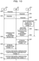
- FIG. 10 is a sequence diagram illustrating an example of operation of the wireless communication system in a case where the quality of the communication channel in one direction is degraded and where the switching instruction is not received, in the third embodiment;
- FIG. 11 is a sequence diagram illustrating an example of operation of a wireless communication system according to a fourth embodiment
- FIG. 12 is a sequence diagram illustrating an example of operation of the wireless communication system in the case where the switching instruction is not received, in the fourth embodiment
- FIG. 13 is a sequence diagram illustrating an example of operation of the wireless communication system in the case where the quality of the communication channel in one direction is degraded, in the fourth embodiment
- FIG. 14 is a sequence diagram illustrating an example of operation of the wireless communication system in the case where the quality of the communication channel in one direction is degraded and where the switching instruction is not received in any UE, in the fourth embodiment;
- FIG. 15 is a diagram illustrating an example of a wireless communication system according to a fifth embodiment
- FIG. 16 is a diagram illustrating an example of a wireless communication system according to a sixth embodiment.
- FIG. 17 is a sequence diagram illustrating an example of operation of the wireless communication system according to the sixth embodiment.
- FIG. 18 is a sequence diagram illustrating an example of operation of a wireless communication system according to a seventh embodiment
- FIG. 19 is a sequence diagram illustrating an example of operation of a wireless communication system according to an eighth embodiment.
- FIG. 20 is a diagram illustrating an example of first wireless communication apparatuses that are described in the first to ninth embodiments and of a communication apparatus that realizes a function of an eNB;
- FIG. 21 is a diagram illustrating an example of a communication apparatus that realizes a function of a second wireless communication apparatus or UE that is described in the first to ninth embodiments.
- An object of the technology disclosed in the present application is to provide a wireless communication apparatus, a wireless communication system, and a processing method that are capable of realizing switching between a communication channel that is used for cellular communication or the like and a communication channel that is used for D2D communication or the like.
- FIG. 1 is a diagram illustrating an example of a wireless communication system 10 according to a first embodiment.
- the wireless communication system 10 according to the first embodiment includes a first wireless communication apparatus 1 , a second wireless communication apparatus 4 - 1 , and a second wireless communication apparatus 4 - 2 .
- the first wireless communication apparatus 1 has a control unit 2 and a communication unit 3 .
- the second wireless communication apparatus 4 - 1 has a control unit 5 - 1 and a communication unit 6 - 1 .
- the second wireless communication apparatus 4 - 2 has a control unit 5 - 2 and a communication unit 6 - 2 .
- the second wireless communication apparatus 4 - 1 and the second wireless communication apparatus 4 - 2 possibly performs wireless communication via a first communication channel 7 .
- the second wireless communication apparatus 4 - 1 possibly performs wireless communication with the first wireless communication apparatus 1 via a second communication channel 8 - 1 between the second wireless communication apparatus 4 - 1 itself and the first wireless communication apparatus 1
- the second wireless communication apparatus 4 - 2 possibly performs wireless communication with the first wireless communication apparatus 1 via a second communication channel 8 - 2 between the second wireless communication apparatus 4 - 2 itself and the first wireless communication apparatus 1
- the first communication channel 7 is used, for example, for the D2D communication
- the second communication channels 8 - 1 and 8 - 2 are used, for example for the cellular communication.
- the second wireless communication apparatus 4 - 1 and the second wireless communication apparatus 4 - 2 are collectively referred to without being distinguished from each other, the second wireless communication apparatus 4 - 1 and the second wireless communication apparatus 4 - 2 will be collectively described below as the second wireless communication apparatus 4 .
- the control unit 5 - 1 and the control unit 5 - 2 are collectively referred to without being distinguished from each other, the control unit 5 - 1 and the control unit 5 - 2 will be described below as the control unit 5 .
- the communication unit 6 - 1 and the communication unit 6 - 2 are collectively referred to without being distinguished from each other, the communication unit 6 - 1 and the communication unit 6 - 2 will be collectively described below as the communication unit 6 . Furthermore, in a case where the second communication channel 8 - 1 and the second communication channel 8 - 2 are collectively referred to without being distinguished from each other, the second communication channel 8 - 1 and the second communication channel 8 - 2 will be collectively described below as the second communication channel 8 .
- the communication unit 6 of each second wireless communication apparatus 4 possibly performs wireless communication via the first communication channel 7 between the second wireless communication apparatus 4 itself and one other second wireless communication apparatus 4 , and possibly performs wireless communication via the second communication channel 8 between the second wireless communication apparatus 4 itself and the first wireless communication apparatus 1 .
- the control unit 5 of each second wireless communication apparatus 4 controls the communication unit 6 and thus establishes the second communication channel 8 .
- the switching instruction for example, is a signal at Layer 2 or Layer 3 of Open Systems Interconnection (OSI) Reference Model.
- OSI Open Systems Interconnection
- the control unit 5 performs control that causes switching to occur from the wireless communication with one other second wireless communication apparatus 4 via the first communication channel 7 to the wireless communication via the second communication channel 8 .
- each second wireless communication apparatus 4 can realize switching between the first communication channel 7 that is used for the D2D communication or the like and the second communication channel 8 that is used for the cellular communication or the like.
- control unit 5 of each second wireless communication apparatus 4 controls the communication unit 6 and thus establishes the second communication channel 8 between the second wireless communication apparatus itself and the first wireless communication apparatus 1 . Then, the control unit 5 controls the communication unit 6 and thus causes the switching to occur from the communication with one other second wireless communication apparatus 4 via the first communication channel 7 to the wireless communication via the second communication channel 8 . Accordingly, the second wireless communication apparatus 4 can suppress occurrence of interruption of communication with one other second wireless communication apparatus 4 .
- the control unit 5 controls the communication unit 6 and thus transmits the switching instruction to one other the second wireless communication apparatus 4 via the first communication channel 7 . Then, in a case where a response to the switching instruction is received, the control unit 5 controls the communication unit 6 , and thus establishes the second communication channel 8 between the second wireless communication apparatus 4 itself and the first wireless communication apparatus 1 and causes the switching to occur from the communication with one other second wireless communication apparatus 4 via the first communication channel 7 to the wireless communication via the second communication channel 8 .
- a plurality of second wireless communication apparatuses 4 can synchronize communication channels that are used for communication, to each other, and can switch between the communication channels. Accordingly, the time for which transmission data stays within each second wireless communication apparatus 4 can be shortened, and a size of a transmission buffer that is provided within each second wireless communication apparatus 4 can be decreased.
- the control unit 5 controls the communication unit 6 , and thus establishes the second communication channel 8 between the second wireless communication apparatus 4 itself and the first wireless communication apparatus 1 . Then, the control unit 5 controls the communication unit 6 and thus causes the switching to occur from the communication with one other second wireless communication apparatus 4 via the first communication channel 7 to the wireless communication via the second communication channel 8 . Accordingly, the second wireless communication apparatus 4 can suppress more reliably the occurrence of the interruption of the communication with one other second wireless communication apparatus 4 .
- the control unit 5 controls the communication unit 6 and thus transmits a result of determination of the quality of the first communication channel 7 to the first wireless communication apparatus 1 .
- the communication unit 3 of the first wireless communication apparatus 1 receives the result of the determination that is transmitted from the second wireless communication apparatus 4 .
- the control unit 2 of the first wireless communication apparatus 1 controls the communication units 3 , and thus transmits the switching instruction that is a signal at Layer 2 or Layer 3, to each of the plurality of second wireless communication apparatuses, for example, to the second wireless communication apparatuses 4 - 1 and 4 - 2 . Then, the control unit 2 controls the communication unit 3 , and thus performs control that establishes the second communication channel 8 between each of the plurality of second wireless communication apparatuses, for example, between the second wireless communication apparatuses 4 - 1 and 4 - 2 .
- the control unit 5 of the second wireless communication apparatus 4 controls the communication unit 6 , and thus the second communication channel 8 between the second wireless communication apparatus 4 itself and the first wireless communication apparatus 1 . Then, the control unit 5 controls the communication unit 6 and thus causes the switching to occur from the communication with one other second wireless communication apparatus 4 via the first communication channel 7 to the wireless communication via the second communication channel 8 .
- the switching is caused to occur between the communication channels that are used by the second wireless communication apparatuses 4 for communication, according to the switching instructions that are received from the first wireless communication apparatus 1 , and thus the suppression of the occurrence of the interruption of the communication between the second wireless communication apparatuses 4 can be realized with high reliability.
- the control unit 5 may control the communication unit 6 and thus may establish the second communication channel 8 between the second wireless communication apparatus 4 itself and the first wireless communication apparatus 1 . Then, the control unit 5 controls the communication unit 6 and thus causes the switching to occur from the wireless communication with the second wireless communication apparatus 4 via the first communication channel 7 to the wireless communication via the second communication channel 8 . Accordingly, the second wireless communication apparatus 4 can suppress more reliably the occurrence of the interruption of the communication with one other second wireless communication apparatus 4 .
- FIG. 2 is a diagram illustrating an example of a wireless communication system 10 according to a second embodiment.
- the second embodiment is equivalent to an embodiment that is more specific in concept than the first embodiment.
- the wireless communication system 10 according to the second embodiment includes an evolved Node B (eNB) 20 , user equipment (UE) 30 - 1 , and UE 30 - 2 .
- the UE 30 - 1 has a control unit 31 - 1 and a communication unit 32 - 1 .
- the UE 30 - 2 has a control unit 31 - 2 and a communication unit 32 - 2 .
- the UE 30 - 1 and the UE 30 - 2 possibly perform the D2D communication via the communication channel 15 .
- the communication channel 15 is also referred to as a sidelink radio bearer (SLRB).
- SLRB sidelink radio bearer
- the UE 30 - 1 possibly performs the cellular communication with the eNB 20 via a communication channel 14 - 1 between the UE 30 - 1 itself and the eNB 20
- the UE 30 - 2 possibly performs the cellular communication with eNB 20 via a communication channel 14 - 2 between the UE 30 - 2 itself and the eNB 20 .
- the UE 30 - 1 and the UE 30 - 2 will be collectively described below as the UE 30 .
- the control unit 31 - 1 and the control unit 31 - 2 are collectively referred to without being distinguished from each other, the control unit 31 - 1 and the control unit 31 - 2 will be collectively described below as the control unit 31
- the communication unit 32 - 1 and the communication unit 32 - 2 will be collectively described below as the communication unit 32 .
- the communication channel 14 - 1 and the communication channel 14 - 2 will be collectively described below as the communication channel 14 .
- the eNB 20 is an example of a base station, and the UE 30 is an example of a terminal or a mobile station.
- the eNB 20 is an example of the first wireless communication apparatus 1 according to the first embodiment, and the UE 30 is an example of the second wireless communication apparatus 4 according to the first embodiment.
- the communication channel 15 is an example of the first communication channel 7 according to the first embodiment, and each communication channel 14 is an example of the second communication channel 8 .
- the eNB 20 is connected, for example, to a core network 12 such as an evolved packet core (EPC).
- EPC evolved packet core
- the eNB 20 establishes the communication channel 14 between the eNB 20 itself and the UE 30 and establishes a communication channel 13 between the eNB 20 itself and a packet data network gateway (PGW) 11 on the core network 12 .
- the communication channel 13 and the communication channel 14 is also referred to, for example, as an evolved packet system (EPS).
- EPS evolved packet system
- a default bearer is included in, and an individual bearer, as occasion demands, is added to the communication channel 13 and the communication channel 14 .
- the communication channel 14 is also referred to as a wireless bearer.
- the communication channel 13 , the communication channel 14 , and the communication channel 15 may be referred to as calls.
- a communication channel 13 - 1 and the communication channel 14 - 1 are established between the UE 30 - 1 and the PGW 11
- a communication channel 13 - 2 and the communication channel 14 - 2 are established between the UE 30 - 2 and the PGW 11 .
- the UE 30 proceeds to an RRC connection mode.
- the communication channel 13 - 1 and the communication channel 13 - 2 are collectively referred to without being distinguished from each other, the communication channel 13 - 1 and the communication channel 13 - 2 will be collectively described below as the communication channel 13 .
- the control unit 31 of the UE 30 controls the communication unit 32 and thus establishes the communication channel 15 between the UE 30 itself and the one other piece of UE 30 .
- the control unit 31 establishes the communication channel 15 , for example, using a resource that is allocated from the eNB 20 . Then, the control unit 31 of the UE 30 controls the communication unit 32 and thus performs the D2D communication with the one other piece of UE 30 via the established communication channel 15 .
- FIG. 3 is a diagram illustrating an example of a format of a synchronization frame 40 that is transmitted and received during the D2D communication.
- PSBCH, PSSS, DMRS, SSSS, and a guard are included in the synchronization frame 40 .
- the PSBCH is an acronym for Physical Sidelink Broadcast Channel
- the PSSS is an acronym for Primary Sidelink Synchronization Signal.
- the DMRS is an acronym for Demodulation Reference Signal
- the SSSS is an acronym for Secondary Sidelink Synchronization Signal.
- the control unit 31 of the UE 30 measures a quality of the communication channel 15 .
- the control unit 31 measures reception qualities of the PSSS and the SSSS that are included in the synchronization frame 40 , as the quality of the communication channel 15 . For example, based on error rates of the PSSS and the SSSS, or the like, the control unit 31 measures a reception quality of the synchronization frame 40 . In a case where the quality of the communication channel 15 is poorer than a predetermined quality, the control unit 31 causes a timer to be reset for restarting.
- the time that is measured by the timer is the time that is equal to or smaller than the processing time that is allowed for processing for a handover, and for example, is the time in a range for several tens milliseconds to 200 milliseconds.
- the control unit 31 causes the timer to stop.
- the control unit 31 controls the communication unit 32 and thus transmits a communication channel establishment request to the eNB 20 and establishes the communication channel 14 between the UE 30 itself and the eNB 20 .
- the communication channel establishment request is a signal at Layer 2 or Layer 3 of the OSI reference model.
- the default bearer is included in, and the individual bearer, as occasion demands, is added to the communication channel 14 that is established by the control unit 31 between the UE 30 itself and the eNB 20 . Furthermore, when the communication channel 14 is established between the UE 30 itself and the eNB 20 , the control unit 31 performs processing such as semi-persistent scheduling (SPS) activation.
- SPS semi-persistent scheduling
- the control unit 31 controls the communication unit 32 and thus causes switching to occur from wireless communication with one other piece of UE 30 via the communication channel 15 to wireless communication via the communication channel 14 that is established between the UE 30 itself and the eNB 20 .
- wireless communication between the UE 30 - 1 and the UE 30 - 2 switches from the wireless communication via the communication channel 15 to the wireless communication via the communication channel 13 and the communication channel 14 .
- FIG. 4 is a diagram illustrating an example of a flow of data after the switching.
- FIG. 5 is a sequence diagram illustrating an example of operation of the wireless communication system 10 according to the second embodiment. It is noted that, before a sequence that is illustrated in FIG. 5 , each of the UE 30 - 1 and the UE 30 - 2 performs the initial access between each of the UE 30 - 1 and the UE 30 - 2 themselves and the eNB 20 , and proceeds to a connection mode. Furthermore, before the sequence that is illustrated in FIG. 5 , the UE 30 - 1 and the UE 30 - 2 establish the communication channel 15 and perform the D2D communication via the communication channel 15 .
- the UE 30 - 1 and the UE 30 - 2 periodically transmit the synchronization frame 40 including the PSSS and the SSSS, via the communication channel 15 (S 100 and S 101 ).
- the UE 30 - 2 measures the quality of the communication channel 15 based on the reception quality of the synchronization frame 40 that is transmitted from the UE 30 - 1 , and determines whether or not the measured quality of the communication channel 15 is poorer than the predetermined quality.
- the UE 30 - 2 detects a degradation in the quality of the communication channel 15 (S 104 ). In a case where the degradation in the quality of the communication channel 15 is detected, the UE 30 - 2 causes a timer 2 that measures a predetermined time, to be reset for restarting. Then, in a case where the timer 2 expires, the UE 30 - 2 transmits the communication channel establishment request to the eNB 20 (S 105 ). Then, the UE 30 - 2 establishes the communication channel 14 - 2 between the UE 30 - 2 itself and the eNB 20 (S 106 ).
- the UE 30 - 1 measures the quality of the communication channel 15 based on the reception quality of the synchronization frame 40 that is transmitted from the UE 30 - 2 , and determines whether or not the measured quality of the communication channel 15 is poorer than the predetermined quality. In the case where the quality of the communication channel 15 is poorer than the predetermined quality (S 103 ), the UE 30 - 1 detects the degradation in the quality of the communication channel 15 (S 107 ).
- the UE 30 - 1 causes a timer 1 that measures a predetermined time, to be reset for restarting. Then, in a case where the timer 1 expires, the UE 30 - 1 transmits the communication channel establishment request to the eNB 20 (S 108 ). Then, the UE 30 - 1 establishes the communication channel 14 - 1 between the UE 30 - 1 itself and the eNB 20 ( 8109 ).
- each of the UE 30 - 1 and the UE 30 - 2 causes switching to occur from communication via the communication channel 15 to communication via the communication channel 14 that is established between each of the UE 30 - 1 and the UE 30 - 2 themselves and the eNB 20 , and continues performing the communication ( 8110 ).
- the UE 30 in a case where, during wireless communication with one other piece of UE 30 via the communication channel 15 , a state where the quality of the communication channel 15 is poorer than the predetermined quality continues for a predetermined time or longer, the UE 30 according to the present embodiment establishes the communication channel 14 between the UE 30 itself and the eNB 20 . Then, the UE 30 causes the switching to occur from the wireless communication with one other piece of UE 30 via the communication channel 15 to the wireless communication via the communication channel 14 . Accordingly, the UE 30 can suppress occurrence of interruption of communication with one other piece of UE 30 due to the degradation in the quality of the communication channel 15 .
- FIG. 6 is a sequence diagram illustrating an example of operation of the wireless communication system 10 in a case where the quality of the communication channel 15 in one direction is degraded, in the second embodiment. It is noted that, in an example that is illustrated in FIG.
- the communication channel 14 and the communication channel 15 via which a signal is transmitted from the UE 30 - 1 to the UE 30 - 2 , and the communication channel 14 and the communication channel 15 via which a signal is transmitted from the UE 30 - 2 to the UE 30 - 1 are separately managed.
- the UE 30 - 1 and the UE 30 - 2 periodically transmit the synchronization frame 40 including the PSSS and the SSSS, via the communication channel 15 (S 120 and S 121 ).
- the UE 30 - 2 measures the quality of the communication channel 15 based on the reception quality of the synchronization frame 40 that is transmitted from the UE 30 - 1 , and determines whether or not the measured quality of the communication channel 15 is poorer than the predetermined quality. In the example that is illustrated in FIG.
- the UE 30 - 2 Because the quality of the communication channel 15 via which a signal is transmitted from the UE 30 - 1 to the UE 30 - 2 is better than the predetermined quality, the UE 30 - 2 does not detect the degradation in the quality of the communication channel 15 . On the other hand, because the quality of the communication channel 15 via which a signal is transmitted from UE 30 - 2 to UE 30 - 1 is poorer than the predetermined quality, the UE 30 - 1 detects the degradation in the quality of the communication channel 15 (S 124 ). In the case where the degradation in the quality of the communication channel 15 is detected, the UE 30 - 1 causes the timer 1 to start.
- the UE 30 - 1 transmits the communication channel establishment request that requests establishment of the communication channel 14 - 1 via which a signal is transmitted from the UE 30 - 2 to the UE 30 - 1 , to the eNB 20 (S 125 ). Then, the UE 30 - 1 establishes the communication channel 14 - 1 via which a signal is transmitted from the UE 30 - 2 to the UE 30 - 1 , between the UE 30 - 1 itself and the eNB 20 (S 126 ).
- the eNB 20 transmits a communication channel establishment instruction that instructs the UE 30 - 2 to establish the communication channel 14 - 2 via which a signal is transmitted from the UE 30 - 2 to the UE 30 - 1 , to the UE 30 - 2 (S 127 ).
- the communication channel establishment instruction for example, is a signal at Layer 2 or Layer 3 of the OSI reference model.
- the UE 30 - 2 establishes the communication channel 14 - 2 via which data is transmitted from the UE 30 - 2 to the UE 30 - 1 , between the UE 30 - 2 itself and the eNB 20 (S 128 ).
- each of the UE 30 - 1 and the UE 30 - 2 continues performing the communication from the UE 30 - 2 to the UE 30 - 1 via the communication channel 14 that is established between each of the UE 30 - 1 and the UE 30 - 2 themselves and the eNB 20 (S 129 ).
- the UE 30 - 2 transmits data, which is destined for UE 30 - 1 , via the communication channel 14 - 2 that is established between the UE 30 - 2 itself and the eNB 20
- the UE 30 - 1 receives the data from the UE 30 - 2 via the communication channel 14 - 1 that is established between the UE 30 - 1 itself and the eNB 20 .
- the communication from the UE 30 - 1 to the UE 30 - 2 is continuously performed via the communication channel 15 that is established between the UE 30 - 1 and the UE 30 - 2 (S 130 ).
- the UE 30 in a case where, during the wireless communication with one other piece of UE 30 via the communication channel 15 , the quality of the communication channel 15 in one direction is degraded, the UE 30 establishes the communication channel 14 between the UE 30 itself and the eNB 20 for the wireless communication in the one direction, of which the quality is degraded. Then, the UE 30 switches the wireless communication in the one direction, of which the quality is degraded, from the wireless communication via the communication channel 15 to the wireless communication via the communication channel 14 . Accordingly, the UE 30 can suppress the occurrence of the interruption of the communication with one other piece of UE 30 due to the degradation in the quality of the communication channel 15 in the one direction.
- the UE 30 transmits the switching instruction to the one other piece of UE 30 in communication, via the communication channel 15 . Then, the UE 30 in transmission via the communication channel 15 establishes the communication channel 14 between the UE 30 itself and the eNB 20 . Then, the UE 30 causes the switching to occur from the wireless communication via the communication channel 15 to the wireless communication via the communication channel 14 that is established between the UE 30 itself and the eNB 20 .
- a configuration of a wireless communication system 10 according to the present embodiment is the same as that of the wireless communication system 10 according to the second embodiment, which is described with reference to FIG. 2 , and thus that a detailed description thereof is omitted.
- the third embodiment is equivalent to an embodiment that is more specific in concept than the first embodiment.
- FIG. 7 is a sequence diagram illustrating an example of operation of the wireless communication system 10 according to the third embodiment. It is noted that, before a sequence that is illustrated in FIG. 7 , each of the UE 30 - 1 and the UE 30 - 2 performs the initial access between each of the UE 30 - 1 and the UE 30 - 2 themselves and the eNB 20 , and proceeds to the connection mode. Furthermore, before the sequence that is illustrated in FIG. 7 , the UE 30 - 1 and the UE 30 - 2 establish the communication channel 15 and perform the D2D communication via the communication channel 15 .
- the UE 30 - 1 and the UE 30 - 2 periodically transmit the synchronization frame 40 including the PSSS and the SSSS, via the communication channel 15 (S 140 and S 141 ).
- the UE 30 - 2 measures the quality of the communication channel 15 based on the reception quality of the synchronization frame 40 that is transmitted from one other piece of UE 30 , and determines whether or not the measured quality of the communication channel 15 is poorer than the predetermined quality. Then, the quality of the communication channel 15 is degraded (S 142 and S 143 ).
- the UE 30 - 2 detects that the quality of the communication channel 15 is degraded to a degree that is lower than the predetermined quality, and thus detects the degradation in the quality of the communication channel 15 (S 144 ). In the case where the degradation in the quality of the communication channel 15 is detected, the UE 30 - 2 transmits the switching instruction to the UE 30 - 1 via the communication channel 15 (S 145 ).
- the switching instruction for example, is a signal at Layer 2 or Layer 3 of the OSI reference.
- the UE 30 - 1 replies to the UE 30 - 2 with a switching response via the communication channel 15 (S 146 ). It is noted that, in a case where there is a master-slave relationship between the UE 30 - 1 and the UE 30 - 2 , in which one is a master and the other is a slave, the UE 30 that operates as a master may detect the degradation in the quality of the communication channel 15 and may transmit the switching instruction to the UE 30 that operates as a slave.
- the UE 30 may detect the degradation in the quality of the communication channel 15 and may transmit the switching instruction to one other piece of UE 30 , and the one other piece of UE 30 may reply with the switching response.
- Step S 146 the UE 30 - 2 receives the switching response from the UE 30 - 1 , the UE 30 - 2 replies to the eNB 20 with the communication channel establishment request (S 150 ). Then, the UE 30 - 2 establishes the communication channel 14 - 2 between the UE 30 - 2 itself and the eNB 20 (S 151 ). Furthermore, the UE 30 - 1 replies to the UE 30 - 2 with the switching response in Step S 146 , and then transmits the communication channel establishment request to the eNB 20 ( 152 ). Then, the UE 30 - 2 establishes the communication channel 14 - 1 between the UE 30 - 1 itself and the eNB 20 (S 153 ).
- each of the UE 30 - 1 and the UE 30 - 2 causes the switching to occur from the communication via the communication channel 15 to the communication via the communication channel 14 that is established between each of the UE 30 - 1 and the UE 30 - 2 themselves and the eNB 20 , and continues performing the communication (S 154 ).
- the UE 30 transmits the switching instruction to the one other piece of UE 30 via the communication channel 15 . Then, in the case where the response to the switching instruction is received, the UE 30 establishes the communication channel 14 between the UE 30 itself and the eNB 20 , and causes the switching to occur from the wireless communication with one other piece of UE 30 via the communication channel 15 to the wireless communication via the communication channel 14 . Accordingly, the UE 30 can synchronize communication channels that are used for communication, to each other, and can switch between the communication channels. Accordingly, the time for which the transmission data stays within the UE 30 can be shortened, and the size of the transmission buffer that is provided within the UE 30 can be decreased.
- FIG. 8 is a sequence diagram illustrating an example of operation of the wireless communication system 10 in a case where the switching instruction is not received, in the third embodiment.
- the UE 30 - 1 and the UE 30 - 2 periodically transmit the synchronization frame 40 including the PSSS and the SSSS, via the communication channel 15 (S 160 and S 161 ).
- the UE 30 - 2 measures the quality of the communication channel 15 based on the reception quality of the synchronization frame 40 that is transmitted from one other piece of UE 30 , and determines whether or not the measured quality of the communication channel 15 is poorer than the predetermined quality. Then, the quality of the communication channel 15 is degraded (S 162 and S 163 ).
- the UE 30 - 2 detects that the quality of the communication channel 15 is degraded to a degree that is lower than the predetermined quality, and thus detects the degradation in the quality of the communication channel 15 (S 164 ).
- the UE 30 - 2 causes the timer 2 to be reset for restarting. Then, the UE 30 - 2 transmits the switching instruction to the UE 30 - 1 via the communication channel 15 (S 165 ).
- the switching instruction that is transmitted from the UE 30 - 2 is not received in the UE 30 - 1 . For this reason, the UE 30 - 1 does not reply with the switching response.
- the UE 30 - 2 transmits the communication channel establishment request to the eNB 20 (S 166 ). Then, the UE 30 - 2 establishes the communication channel 14 - 2 between the UE 30 - 2 itself and the eNB 20 (S 167 ).
- the UE 30 - 1 detects the degradation in the quality of the communication channel 15 (S 168 ). In the case where the degradation in the quality of the communication channel 15 is detected, the UE 30 - 1 causes the timer 1 to be reset for restarting. Then, even in a case where the switching response is not received from the UE 30 - 2 , if the timer 1 expires, the UE 30 - 1 transmits the communication channel establishment request to the eNB 20 (S 169 ).
- the UE 30 - 1 establishes the communication channel 14 - 1 between the UE 30 - 1 itself and the eNB 20 (S 170 ). Then, each of the UE 30 - 1 and UE 30 - 2 causes the switching to occur from the communication via the communication channel 15 to the communication via the communication channel 14 that is established between each of the UE 30 - 1 and the UE 30 - 2 themselves and the eNB 20 , and continues performing the communication (S 171 ).
- the UE 30 in this manner, even in a case where the response to the switching instruction that is transmitted to the one other piece of UE 30 via the communication channel 15 is not received, if the state where the quality of the communication channel 15 is poorer than the predetermined quality continues for the predetermined time or longer, the UE 30 according to the present embodiment establishes the communication channel 14 between the UE 30 itself and the eNB 20 . Then, UE 30 causes the switching to occur from the wireless communication with one other piece of UE 30 via the communication channel 15 to the wireless communication via the communication channel 14 . Accordingly, the UE 30 can suppress the occurrence of the interruption of the communication with one other piece of UE 30 due to the degradation in the quality of the communication channel 15 .
- FIG. 9 is a sequence diagram illustrating an example of operation of the wireless communication system 10 in the case where the quality of the communication channel 15 in one direction is degraded, in the third embodiment. It is noted that, in an example that is illustrated in FIG.
- the communication channel 14 and the communication channel 15 via which a signal is transmitted from the UE 30 - 1 to the UE 30 - 2 , and the communication channel 14 and the communication channel 15 via which a signal is transmitted from the UE 30 - 2 to the UE 30 - 1 are separately managed.
- the UE 30 - 1 and the UE 30 - 2 periodically transmit the synchronization frame 40 including the PSSS and the SSSS, via the communication channel 15 (S 180 and S 181 ).
- the UE 30 - 2 measures the quality of the communication channel 15 based on the reception quality of the synchronization frame 40 that is transmitted from the UE 30 - 1 , and determines whether or not the measured quality of the communication channel 15 is poorer than the predetermined quality. In the example that is illustrated in FIG.
- the UE 30 - 2 detects that the quality of the communication channel 15 via which a signal is transmitted from the UE 30 - 1 to UE 30 - 2 is degraded to a degree that is lower than the predetermined quality, and thus detects the degradation in the quality of the communication channel 15 (S 184 ). In the case where the degradation in the quality of the communication channel 15 is detected, the UE 30 - 2 transmits the switching instruction to the UE 30 - 1 via the communication channel 15 (S 185 ). In a case where the switching instruction is received from the UE 30 - 2 via the communication channel 15 , the UE 30 - 1 replies to the UE 30 - 2 with the switching response via the communication channel 15 (S 186 ).
- the UE 30 - 2 transmits the communication channel establishment request that requests the establishment of the communication channel 14 - 2 via which a signal is transmitted from the UE 30 - 1 to the UE 30 - 2 , to the eNB 20 (S 187 ). Then, the UE 30 - 2 establishes the communication channel 14 - 2 via which a signal is transmitted from the UE 30 - 1 to the UE 30 - 2 , between the UE 30 - 2 itself and the eNB 20 (S 188 ).
- the UE 30 - 1 transmits the communication channel establishment request that requests the eNB 20 to establish the communication channel 14 - 1 via which a signal is transmitted from the UE 30 - 1 to the UE 30 - 2 , the eNB 20 (S 189 ). Then, the UE 30 - 2 establishes the communication channel 14 - 1 via which a signal is transmitted from the UE 30 - 1 to the UE 30 - 2 , between the UE 30 - 2 itself and the eNB 20 (S 190 ).
- each of the UE 30 - 1 and the UE 30 - 2 continues performing the communication from the UE 30 - 1 to the UE 30 - 2 via the communication channel 14 that is established between each of the UE 30 - 1 and the UE 30 - 2 themselves and the eNB 20 (S 191 ).
- the UE 30 - 1 transmits data, which is destined for the UE 30 - 2 , via the communication channel 14 - 1 that is established between the UE 30 - 1 itself and the eNB 20
- the UE 30 - 2 receives the data from the UE 30 - 1 via the communication channel 14 - 2 that is established between the UE 30 - 2 itself and the eNB 20 .
- the communication from the UE 30 - 2 to the UE 30 - 1 is continuously performed via the communication channel 15 that is already established between the UE 30 - 1 and the UE 30 - 2 (S 192 ).
- the UE 30 transmits the switching instruction to the one other piece of UE 30 via the communication channel 15 . Then, in the case where the response to the switching instruction is received, the UE 30 establishes the communication channel 14 between the UE 30 itself and the eNB 20 for the wireless communication in the one direction, of which the quality is degraded. Then, the UE 30 switches the wireless communication in the one direction, of which the quality is degraded, from the wireless communication via the communication channel 15 to the wireless communication via the communication channel 14 . Accordingly, the UE 30 can suppress the occurrence of the interruption of the communication with one other piece of UE 30 due to the degradation in the quality of the communication channel 15 in the one direction.
- FIG. 10 is a sequence diagram illustrating an example of operation of the wireless communication system 10 in a case where the quality of the communication channel in one direction is degraded and where the switching instruction is not received, in the third embodiment. It is noted that, in an example that is illustrated in FIG.
- the communication channel 14 and the communication channel 15 via which a signal is transmitted from the UE 30 - 1 to the UE 30 - 2 , and the communication channel 14 and the communication channel 15 via which a signal is transmitted from the UE 30 - 2 to the UE 30 - 1 are separately managed.
- the UE 30 - 1 and the UE 30 - 2 periodically transmit the synchronization frame 40 including the PSSS and the SSSS, via the communication channel 15 (S 200 and S 201 ).
- the UE 30 - 2 measures the quality of the communication channel 15 based on the reception quality of the synchronization frame 40 that is transmitted from the UE 30 - 1 , and determines whether or not the measured quality of the communication channel 15 is poorer than the predetermined quality. In the example that is illustrated in FIG.
- the quality of the communication channel 15 via which a signal is transmitted from the UE 30 - 1 to the UE 30 - 2 is degraded to a degree that is lower than the quality of the predetermined quality (S 202 ), but that the quality of the communication channel 15 via which a signal is transmitted from the UE 30 - 2 to the UE 30 - 1 is better than the predetermined quality (S 203 ).
- the UE 30 - 2 detects that the quality of the communication channel 15 via which a signal is transmitted from the UE 30 - 1 to UE 30 - 2 is degraded to a degree that is lower than the predetermined quality, and thus detects the degradation in the quality of the communication channel 15 (S 204 ). In the case where the degradation in the quality of the communication channel 15 is detected, the UE 30 - 2 causes the timer 2 to be reset for restarting. Then, the UE 30 - 2 transmits the switching instruction to the UE 30 - 1 via the communication channel 15 (S 205 ). In the example in FIG.
- the UE 30 - 1 does not reply with the switching response. However, even in the case where the switching response is not received, in the case where the timer 2 expires, the UE 30 - 2 transmits the communication channel establishment request that requests the establishment of the communication channel 14 - 2 via which a signal is transmitted from the UE 30 - 1 to the UE 30 - 2 , to the eNB 20 (S 206 ).
- the UE 30 - 2 establishes the communication channel 14 - 2 via which a signal is transmitted from the UE 30 - 1 to the UE 30 - 2 , between the UE 30 - 2 itself and the eNB 20 (S 207 ).
- the eNB 20 transmits the communication channel establishment instruction that instructs the UE 30 - 1 to establish the communication channel 14 - 1 via which a signal is transmitted from the UE 30 - 1 to the UE 30 - 2 , to the UE 30 - 1 (S 208 ).
- the UE 30 - 1 establishes the communication channel 14 - 1 via which a signal is transmitted from the UE 30 - 1 to the UE 30 - 2 , between the UE 30 - 1 itself and the eNB 20 (S 209 ).
- each of the UE 30 - 1 and the UE 30 - 2 continues performing the communication from the UE 30 - 1 to the UE 30 - 2 via the communication channel 14 that is established between each of the UE 30 - 1 and the UE 30 - 2 themselves and the eNB 20 (S 210 ).
- the UE 30 - 1 transmits data, which is destined for the UE 30 - 2 , via the communication channel 14 - 1 that is established between the UE 30 - 1 itself and the eNB 20
- the UE 30 - 2 receives the data from the UE 30 - 1 via the communication channel 14 - 2 that is established between the UE 30 - 2 itself and the eNB 20 .
- the communication from the UE 30 - 2 to the UE 30 - 1 is continuously performed via the communication channel 15 that is already established between the UE 30 - 1 and the UE 30 - 2 (S 211 ).
- the UE 30 in this manner, even in the case where the response to the switching instruction is not received, if the state where the quality of the communication channel 15 is poorer than the predetermined quality continues for the predetermined time or longer, the UE 30 according to the present embodiment establishes the communication channel 14 between the UE 30 itself and the eNB 20 . Then, UE 30 causes the switching to occur from the wireless communication with one other piece of UE 30 via the communication channel 15 to the wireless communication via the communication channel 14 . Accordingly, the UE 30 can suppress the occurrence of the interruption of the communication with one other piece of UE 30 due to the degradation in the quality of the communication channel 15 .
- a result of the measurement of the quality of the communication channel 15 is transmitted to the eNB 20 .
- the eNB 20 establishes the communication channel 14 between the eNB 20 itself and the UE 30 . Then, the eNB 20 instructs the UE 30 to cause the switching to occur from the wireless communication between the piece of UE 30 themselves via the communication channel 15 to the wireless communication via the communication channel 14 between eNBs 20 themselves.
- a configuration of a wireless communication system 10 according to the present embodiment is the same as that of the wireless communication system 10 according to the second embodiment, which is described with reference to FIG. 2 , and thus that a detailed description thereof is omitted.
- the fourth embodiment is equivalent to an embodiment that is more specific in concept than the first embodiment.
- FIG. 11 is a sequence diagram illustrating an example of operation of the wireless communication system 10 according to the fourth embodiment. It is noted that, before a sequence that is illustrated in FIG. 11 , each of the UE 30 - 1 and the UE 30 - 2 performs the initial access between each of the UE 30 - 1 and the UE 30 - 2 themselves and the eNB 20 , and proceeds to the connection mode. Furthermore, before the sequence that is illustrated in FIG. 11 , the UE 30 - 1 and the UE 30 - 2 establish the communication channel 15 and perform the D2D communication via the communication channel 15 .
- the UE 30 - 1 and the UE 30 - 2 periodically transmit the synchronization frame 40 including the PSSS and the SSSS, via the communication channel 15 (S 220 and S 221 ).
- the UE 30 - 2 measures the quality of the communication channel 15 based on the reception quality of the synchronization frame 40 that is transmitted from one other piece of UE 30 , and determines whether or not the measured quality of the communication channel 15 is poorer than the predetermined quality. Then, the quality of the communication channel 15 is degraded (S 222 and S 223 ).
- the UE 30 - 2 detects that the quality of the communication channel 15 is degraded to a degree that is lower than the predetermined quality, and thus detects the degradation in the quality of the communication channel 15 (S 224 ). Then, the UE 30 - 2 transmits a result of measurement of the reception quality of the synchronization frame 40 to the eNB 20 (S 225 ).
- the UE 30 - 1 detects that the quality of the communication channel 15 is degraded to a degree that is lower than the predetermined quality, and thus detects the degradation in the quality of the communication channel 15 (S 226 ). Then, the UE 30 - 1 transmits the result of the measurement of the quality of the communication channel 15 to the eNB 20 (S 227 ).
- the result of the measurement is transmitted, for example, using a measurement report that is an RRC signal. It is noted that as another example, the result of the measurement may be transmitted using any other signal that is used at Layer 2 or Layer 3 of the OSI reference model.
- the eNB 20 transmits the switching instruction to the UE 30 - 1 and the UE 30 - 2 (S 228 and S 229 ).
- the switching instruction for example, is a signal at Layer 2 or Layer 3 of the OSI reference.
- the UE 30 - 2 establishes the communication channel 14 - 2 between the UE 30 - 2 itself and the eNB 20 (S 230 ).
- the UE 30 - 1 establishes the communication channel 14 - 1 between the UE 30 - 1 itself and the eNB 20 (S 231 ).
- each of the UE 30 - 1 and the UE 30 - 2 causes the switching to occur from the communication via the communication channel 15 to the communication via the communication channel 14 that is established between each of the UE 30 - 1 and the UE 30 - 2 themselves and the eNB 20 , and continues performing the communication (S 232 ).
- the UE 30 transmits the result of the measurement of the quality of the communication channel 15 to the eNB 20 .
- the eNB 20 transmits the switching instruction to the UE 30 , and establishes the communication channel 14 between the eNB 20 itself and the UE 30 .
- the UE 30 causes the switching to occur from the wireless communication with one other piece of UE 30 via the communication channel 15 to the wireless communication via the communication channel 14 that is established between the UE 30 itself and the eNB 20 .
- the switching is caused to occur between the communication channels that are used by the pieces of UE 30 for communication, according to the switching instructions that are received from the eNB 20 , and thus the suppression of the occurrence of the interruption of the communication between the pieces of UE 30 themselves can be realized with high reliability.
- FIG. 12 is a sequence diagram illustrating an example of operation of the wireless communication system 10 in the case where the switching instruction is not received, in the fourth embodiment.
- the UE 30 - 1 and the UE 30 - 2 periodically transmit the synchronization frame 40 including the PSSS the SSSS, via the communication channel 15 (S 240 and S 241 ).
- the UE 30 - 2 measures the quality of the communication channel 15 based on the reception quality of the synchronization frame 40 that is transmitted from one other piece of UE 30 , and determines whether or not the measured quality of the communication channel 15 is poorer than the predetermined quality. Then, the quality of the communication channel 15 is degraded (S 242 and S 243 ).
- the UE 30 - 1 and the UE 30 - 2 detect that the quality of the communication channel 15 is degraded to a degree that is lower than the predetermined quality, and thus detect the degradation in the quality of the communication channel 15 (S 244 and S 245 ).
- the UE 30 - 1 causes the timer 1 to be reset for restarting
- the UE 30 - 2 causes the timer 2 to be reset for restarting.
- the UE 30 - 1 and the UE 30 - 2 transmit the result of the measurement of the quality of the communication channel 15 to the eNB 20 (S 246 and S 247 ).
- the eNB 20 transmits the switching instruction to the UE 30 - 1 and the UE 30 - 2 (S 248 and S 249 ).
- the switching instruction that is transmitted from the eNB 20 is received in the UE 30 - 2 , but is not received in the UE 30 - 1 .
- the UE 30 - 2 establishes the communication channel 14 - 2 between the UE 30 - 2 itself and the eNB 20 (S 250 ).
- the UE 30 - 1 does not receive the switching instruction from the eNB 20 , but, due to the expiration of the timer 1 , transmits the communication channel establishment request to the eNB 20 (S 251 ). Then, the UE 30 - 1 establishes the communication channel 14 - 1 between the UE 30 - 1 itself and the eNB 20 (S 252 ). Then, each of the UE 30 - 1 and the UE 30 - 2 causes the switching to occur from the communication via the communication channel 15 to the communication via the communication channel 14 that is established between each of the UE 30 - 1 and the UE 30 - 2 themselves and the eNB 20 and continues performing the communication (S 253 ).
- the UE 30 in this manner, even in the case where the switching instruction is not received from the eNB 20 , if the state where the quality of the communication channel 15 is poorer than the predetermined quality continues for the predetermined time or longer, the UE 30 establishes the communication channel 14 between the UE 30 itself and the eNB 20 . Then, the UE 30 causes the switching to occur from the wireless communication with one other piece of UE 30 via the communication channel 15 to the wireless communication via the communication channel 14 . Accordingly, even in a case where the reception of the switching instruction from the eNB 20 fails, the UE 30 can suppress the occurrence of the interruption of the communication with one other piece of UE 30 due to the degradation in the quality of the communication channel 15 .
- FIG. 13 is a sequence diagram illustrating an example of operation of the wireless communication system 10 in the case where the quality of the communication channel 15 in one direction is degraded, in the fourth embodiment. It is noted that, in an example that is illustrated in FIG.
- the communication channel 14 and the communication channel 15 via which a signal is transmitted from the UE 30 - 1 to the UE 30 - 2 , and the communication channel 14 and the communication channel 15 via which a signal is transmitted from the UE 30 - 2 to the UE 30 - 1 are separately managed.
- the UE 30 - 1 and the UE 30 - 2 periodically transmit the synchronization frame 40 including the PSSS and the SSSS, via the communication channel 15 (S 260 and S 261 ).
- the UE 30 - 2 measures the quality of the communication channel 15 based on the reception quality of the synchronization frame 40 that is transmitted from the UE 30 - 1 , and determines whether or not the measured quality of the communication channel 15 is poorer than the predetermined quality. In the example that is illustrated in FIG.
- the UE 30 - 2 detects that the quality of the communication channel 15 via which a signal is transmitted from the UE 30 - 1 to UE 30 - 2 is degraded to a degree that is lower than the predetermined quality, and thus detects the degradation in the quality of the communication channel 15 (S 264 ). In the case where the degradation in the quality of the communication channel 15 is detected, the UE 30 - 2 transmits the result of the measurement of the quality of the communication channel 15 to the eNB 20 (S 265 ).
- the eNB 20 receives the result of the measurement from the UE 30 - 2 , but does not receive the result of the measurement from the UE 30 - 1 .
- the fact that the result of the measurement is not received from the UE 30 - 1 means that the degradation in the quality of the communication channel 15 is not detected in the UE 30 - 1 .
- the eNB 20 transmits the switching instruction that instructs the UE 30 - 2 to establish the communication channel 14 - 2 via which a signal is transmitted from the UE 30 - 1 to the UE 30 - 2 , to the UE 30 - 2 (S 266 ).
- the UE 30 - 2 establishes the communication channel 14 - 2 via which a signal is transmitted from the UE 30 - 1 to the UE 30 - 2 , between the UE 30 - 2 itself and the eNB 20 (S 267 ).
- the eNB 20 transmits the switching instruction that instructs the UE 30 - 1 to establish the communication channel 14 - 1 via which a signal is transmitted from the UE 30 - 1 to the UE 30 - 2 , to the UE 30 - 1 (S 268 ).
- the UE 30 - 1 establishes the communication channel 14 - 1 via which a signal is transmitted from the UE 30 - 1 to the UE 30 - 2 , between the UE 30 - 1 itself and the eNB 20 (S 269 ).
- each of the UE 30 - 1 and the UE 30 - 2 continues performing the communication from the UE 30 - 1 to the UE 30 - 2 via the communication channel 14 that is established between each of the UE 30 - 1 and the UE 30 - 2 themselves and the eNB 20 (S 270 ).
- the UE 30 - 1 transmits data, which is destined for the UE 30 - 2 , via the communication channel 14 - 1 that is established between the UE 30 - 1 itself and the eNB 20
- the UE 30 - 2 receives the data from the UE 30 - 1 via the communication channel 14 - 2 that is established between the UE 30 - 2 itself and the eNB 20 .
- the communication from the UE 30 - 2 to the UE 30 - 1 is continuously performed via the communication channel 15 that is already established between the UE 30 - 1 and the UE 30 - 2 (S 271 ).
- the eNB 20 establishes the communication channel 14 between the eNB 20 itself and the UE 30 for the wireless communication in the one direction, of which the quality is degraded. Then, the UE 30 switches the wireless communication in the one direction, of which the quality is degraded, from the wireless communication via the communication channel 15 to the wireless communication via the communication channel 14 . Accordingly, the eNB 20 can suppress the occurrence of the interruption of the communication between the pieces of UE 30 themselves due to the degradation in the quality of the communication channel 15 in the one direction.
- FIG. 14 is a sequence diagram illustrating an example of operation of the wireless communication system 10 in the case where the quality of the communication channel in one direction is degraded and where the switching instruction is not received, in the fourth embodiment. It is noted that, in an example that is illustrated in FIG.
- the communication channel 14 and the communication channel 15 via which a signal is transmitted from the UE 30 - 1 to the UE 30 - 2 , and the communication channel 14 and the communication channel 15 via which a signal is transmitted from the UE 30 - 2 to the UE 30 - 1 are separately managed.
- the UE 30 - 1 and the UE 30 - 2 periodically transmit the synchronization frame 40 including the PSSS and the SSSS, via the communication channel 15 (S 280 and S 281 ).
- the UE 30 - 2 measures the quality of the communication channel 15 based on the reception quality of the synchronization frame 40 that is transmitted from the UE 30 - 1 , and determines whether or not the measured quality of the communication channel 15 is poorer than the predetermined quality. In the example that is illustrated in FIG.
- the UE 30 - 2 detects that the quality of the communication channel 15 via which a signal is transmitted from the UE 30 - 1 to UE 30 - 2 is degraded to a degree that is lower than the predetermined quality, and thus detects the degradation in the quality of the communication channel 15 (S 284 ). In the case where the degradation in the quality of the communication channel 15 is detected, the UE 30 - 2 causes the timer 2 to be reset for restarting. Then, the UE 30 - 2 transmits the result of the measurement of the quality of the communication channel 15 to the eNB 20 (S 285 ). The eNB 20 receives the result of the measurement from the UE 30 - 2 , but does not receive the result of the measurement from the UE 30 - 1 .
- the eNB 20 transmits the switching instruction that instructs the UE 30 - 2 to establish the communication channel 14 - 2 via which a signal is transmitted from the UE 30 - 1 to the UE 30 - 2 , to the UE 30 - 2 (S 286 ). Furthermore, the eNB 20 transmits the switching instruction that instructs the UE 30 - 1 to establish the communication channel 14 - 1 via which a signal is transmitted from the UE 30 - 1 to the UE 30 - 2 , to the UE 30 - 1 (S 287 ). However, the switching instruction that is transmitted from the eNB 20 is not received in any one of the UE 30 - 1 and the UE 30 - 2 .
- the UE 30 - 2 transmits the communication channel establishment request that requests the establishment of the communication channel 14 - 2 via which a signal is transmitted from the UE 30 - 1 to UE 30 - 2 , to the eNB 20 (S 288 ). Then, the UE 30 - 2 establishes the communication channel 14 - 2 via which a signal is transmitted from the UE 30 - 1 to the UE 30 - 2 , between the UE 30 - 2 itself and the eNB 20 (S 289 ).
- the eNB 20 transmits the communication channel establishment instruction that instructs the UE 30 - 1 to establish the communication channel 14 - 1 via which a signal is transmitted from the UE 30 - 1 to the UE 30 - 2 , to the UE 30 - 1 (S 290 ). Then, the UE 30 - 1 establishes the communication channel 14 - 1 via which a signal is transmitted from the UE 30 - 1 to the UE 30 - 2 , between the UE 30 - 1 itself and the eNB 20 (S 291 ).
- each of the UE 30 - 1 and the UE 30 - 2 continues performing the communication from the UE 30 - 1 to the UE 30 - 2 via the communication channel 14 that is established between each of the UE 30 - 1 and the UE 30 - 2 themselves and the eNB 20 (S 292 ).
- the UE 30 - 1 transmits data, which is destined for the UE 30 - 2 , via the communication channel 14 - 1 that is established between the UE 30 - 1 itself and the eNB 20
- the UE 30 - 2 receives the data from the UE 30 - 1 via the communication channel 14 - 2 that is established between the UE 30 - 2 itself and the eNB 20 .
- the communication from the UE 30 - 2 to the UE 30 - 1 is continuously performed via the communication channel 15 that is already established between the UE 30 - 1 and the UE 30 - 2 (S 293 ).
- the UE 30 in this manner, even in the case where the switching instruction is not received from the eNB 20 , if the state where the quality of the communication channel 15 is poorer than the predetermined quality continues for the predetermined time or longer, the UE 30 establishes the communication channel 14 between the UE 30 itself and the eNB 20 . Then, the UE 30 causes the switching to occur from the wireless communication with one other piece of UE 30 via the communication channel 15 to the wireless communication via the communication channel 14 . Accordingly, the UE 30 can suppress the occurrence of the interruption of the communication with one other piece of UE 30 due to the degradation in the quality of the communication channel 15 .
- FIG. 15 is a diagram illustrating an example of a wireless communication system 10 according to a fifth embodiment.
- the wireless communication system 10 according to the fifth embodiment includes a plurality of first wireless communication apparatuses 1 - 1 and a plurality of first wireless communication apparatuses 1 - 2 , and a plurality of second wireless communication apparatuses 4 - 1 and a plurality of second wireless communication apparatuses 4 - 2 .
- the first wireless communication apparatus 1 - 1 has a control unit 2 - 1 and a communication unit 3 - 1 .
- the first wireless communication apparatus 1 - 2 has a control unit 2 - 2 and a communication unit 3 - 2 .
- the second wireless communication apparatus 4 - 1 has the control unit 5 - 1 and the communication unit 6 - 1 .
- the second wireless communication apparatus 4 - 2 has the control unit 5 - 2 and the communication unit 6 - 2 .
- the second wireless communication apparatuses 4 - 1 and 4 - 2 possibly perform communication through the first wireless communication apparatus 1 - 1 within a cell of the first wireless communication apparatus 1 - 1 , and possibly perform communication through the first wireless communication apparatus 1 - 2 within a cell of the first wireless communication apparatus 1 - 2 .
- the second wireless communication apparatuses 4 - 1 and 4 - 2 possibly perform communication via the first communication channel 7 .
- the first communication channel 7 for example, is used for the D2D communication.
- the first wireless communication apparatuses 1 - 1 and 1 - 2 will be described below as the first wireless communication apparatus 1 .
- the control unit 2 - 1 and the control unit 2 - 2 are collectively referred to without being distinguished from each other, the control unit 2 - 1 and the control unit 2 - 2 will be collectively described below as the control unit 2
- the communication unit 3 - 1 and the communication unit 3 - 2 are collectively named without being distinguished from each other, the communication unit 3 - 1 and the communication unit 3 - 2 will be collectively described below as the communication unit 3 .
- the second wireless communication apparatuses 4 - 1 and 4 - 2 belong to the first wireless communication apparatus 1 - 1 , and perform wireless communication via the first communication channel 7 . Then, a handover occurs from the second wireless communication apparatus 4 - 2 to one other first wireless communication apparatus 1 - 2 , and the second wireless communication apparatuses 4 - 1 and 4 - 2 updates a resource for the first communication channel 7 , based on information on a resource that is allocated from the first wireless communication apparatus 1 - 2 that is a handover destination. Accordingly, communication between the second wireless communication apparatus 4 - 1 and the second wireless communication apparatus 4 - 2 is continuously performed via the first communication channel 7 .
- each second wireless communication apparatus 4 possibly performs wireless communication between the first wireless communication apparatus 1 and one other second wireless communication apparatus 4 .
- the communication unit 6 possibly performs the wireless communication via the first communication channel 7 between the second wireless communication apparatus 4 itself and the one other second wireless communication apparatus 4 .
- the control unit 5 - 2 of the second wireless communication apparatus 4 - 2 that performs the wireless communication via the first communication channel 7 between the second wireless communication apparatus 4 - 2 itself and the second wireless communication apparatus 4 - 1 receives information on a resource that is allocated by the first wireless communication apparatus 1 - 2 , from the first wireless communication apparatus 1 - 1 or the first wireless communication apparatus 1 - 2 .
- control unit 5 - 1 of the second wireless communication apparatus 4 - 1 receives the information on the resource that is allocated by the first wireless communication apparatus 1 - 2 which is the handover destination of the second wireless communication apparatus 4 - 2 , from the second wireless communication apparatus 4 - 2 or the first wireless communication apparatus 1 - 1 . Then, the control unit 5 - 1 of the second wireless communication apparatus 4 - 1 and the control unit 5 - 2 of the second wireless communication apparatus 4 - 2 updates resources, such as frequency bands, that are used for the first communication channel 7 , based on the received information on the resource.
- resources such as frequency bands
- the second wireless communication apparatus 4 - 1 and the second wireless communication apparatus 4 - 2 can continue performing the wireless communication via the first communication channel 7 , the resource for which is updated, without contending for the source that is allocated by the first wireless communication apparatus 1 - 2 which is the handover destination.
- the control unit 2 - 1 of the first wireless communication apparatus 1 - 1 receives the information on the resource that is allocated from the first wireless communication apparatus 1 - 2 that is the handover designation, from the first wireless communication apparatus 1 - 2 through the communication unit 3 - 1 . Then, the control unit 2 - 1 transmits the information on the resource that is allocated from the first wireless communication apparatus 1 - 2 , to the second wireless communication apparatus 4 - 2 through the communication unit 3 - 1 .
- the control unit 5 - 2 of the second wireless communication apparatus 4 - 2 receives the information on the resource that is allocated from the first wireless communication apparatus 1 - 2 that is the handover destination, from the first wireless communication apparatus 1 - 1 through the communication unit 6 - 2 . Then, the control unit 5 - 2 transmits information on a resource, which is received from the first wireless communication apparatus 1 - 1 , to the second wireless communication apparatus 4 - 1 via the first communication channel 7 , using the communication unit 6 - 2 . Then, the control unit 5 - 2 updates the resource that is used for the first communication channel 7 , based on the information on the resource, which is received from the first wireless communication apparatus 1 - 1 .
- the control unit 5 - 1 of the second wireless communication apparatus 4 - 1 updates the resource that is used for the first communication channel 7 , based on the received information on the resource. Accordingly, even in the case where the second wireless communication apparatus 4 - 2 performs a handover, the second wireless communication apparatus 4 - 1 and the second wireless communication apparatus 4 - 2 can continue performing the D2D communication via the first communication channel 7 , the resource for which is updated, without contending for the resource that is allocated by the first wireless communication apparatus 1 - 2 which is the handover destination.
- the control unit 2 - 1 of the first wireless communication apparatus 1 - 1 receives the information on the resource that is allocated from the first wireless communication apparatus 1 - 2 that is the handover designation, from the first wireless communication apparatus 1 - 2 through the communication unit 3 - 1 . Then, the control unit 2 - 1 transmits the information on the resource that is allocated from the first wireless communication apparatus 1 - 2 , to each of the second wireless communication apparatus 4 - 1 and the second wireless communication apparatus 4 - 2 through the communication unit 3 - 1 .
- the control unit 5 - 1 of the second wireless communication apparatus 4 - 1 receives the information on the resource that is allocated by the first wireless communication apparatus 1 - 2 which is the handover destination, from the first wireless communication apparatus 1 - 1 through the communication unit 6 - 1 , and, based on the received information on the resource, updates the resource that is used for the first communication channel 7 .
- the control unit 5 - 2 of the second wireless communication apparatus 4 - 2 receives the information on the resource that is allocated by the first wireless communication apparatus 1 - 2 which is the handover destination, from the first wireless communication apparatus 1 - 1 through the communication unit 6 - 2 , and, based on the received information on the resource, updates the resource that is used from the first communication channel 7 .
- the second wireless communication apparatus 4 - 1 and the second wireless communication apparatus 4 - 2 can continue performing the D2D communication via the first communication channel 7 , the resource for which is updated. Furthermore, the first wireless communication apparatus 1 - 1 transmits the information on the resource that is allocated from the first wireless communication apparatus 1 - 2 that is the handover destination, to each of the second wireless communication apparatus 4 - 1 and the second wireless communication apparatus 4 - 2 . For this reason, the second wireless communication apparatus 4 - 1 and the second wireless communication apparatus 4 - 2 can receive the information on the resource that is allocated from the first wireless communication apparatus 1 - 2 which is the handover destination, with high reliability.
- the control unit 2 - 1 of the first wireless communication apparatus 1 - 1 receives the information on the resource that is allocated from the first wireless communication apparatus 1 - 2 which is the handover designation, from the first wireless communication apparatus 1 - 2 through the communication unit 3 - 1 . Then, the control unit 2 - 1 transmits the information on the resource, which is received from the first wireless communication apparatus 1 - 2 , to the second wireless communication apparatus 4 - 1 through the communication unit 3 - 1 .
- the control unit 2 - 2 of the first wireless communication apparatus 1 - 2 transmits the information on the resource to the second wireless communication apparatus 4 - 2 through the communication unit 3 - 2 .
- the control unit 5 - 1 of the second wireless communication apparatus 4 - 1 updates the resource that is used for the first communication channel 7 , through the communication unit 6 - 1 .
- the control unit 5 - 2 of the second wireless communication apparatus 4 - 2 updates the resource that is used for the first communication channel 7 , through the communication unit 6 - 2 .
- the second wireless communication apparatus 4 - 1 and the second wireless communication apparatus 4 - 2 can continue performing the D2D communication via the first communication channel 7 , the resource for which is updated. Furthermore, the information on the resource that is allocated by the first wireless communication apparatus 1 - 2 which is a handover source is transmitted from the first wireless communication apparatus 1 - 1 to the second wireless communication apparatus 4 - 1 , and is transmitted from the first wireless communication apparatus 1 - 2 that is handover destination, to the second wireless communication apparatus 4 - 2 . Accordingly, a processing load on each first wireless communication apparatus 1 , which results when the information on the resource is transmitted to each wireless communication apparatus 4 can be distributed.
- FIG. 16 is a diagram illustrating an example of a wireless communication system 10 according to a sixth embodiment.
- the sixth embodiment is equivalent to an embodiment that is more specific in concept than the fifth embodiment.
- the wireless communication system 10 according to the sixth embodiment includes an eNB 20 - 1 , an eNB 20 - 2 , the UE 30 - 1 , and the UE 30 - 2 .
- the eNB 20 - 1 has a control unit 21 - 1 and a communication unit 22 - 1 .
- the eNB 20 - 2 has a control unit 21 - 2 and a communication unit 22 - 2 .
- the UE 30 - 1 has the control unit 31 - 1 and the communication unit 32 - 1 .
- the UE 30 - 2 has a control unit 31 - 2 and a communication unit 32 - 2 .
- the UE 30 - 1 and the UE 30 - 2 possibly perform the D2D communication via the communication channel 15 .
- the communication channel 15 is also referred to as an SLRB.
- the UE 30 - 1 possibly performs the cellular communication with the eNB 20 - 1 via the communication channel 14 - 1 between the UE 30 - 1 itself and the eNB 20 - 1
- the UE 30 - 2 possibly performs the cellular communication with the communication channel 14 - 2 between the UE 30 - 2 itself and the eNB 20 - 1 or the eNB 20 - 2 .
- the eNB 20 - 1 and the eNB 20 - 2 are collectively referred to without being distinguished from each other, the eNB 20 - 1 and the eNB 20 - 2 are collectively expressed as the eNB 20 .
- the control unit 21 - 1 and the control unit 21 - 2 are collectively referred to without being distinguished from each other, the control unit 21 - 1 and the control unit 21 - 2 will be collectively described below as the control unit 21
- the communication units 22 - 1 and 22 - 2 are collectively named without being distinguished from each other, the communication units 22 - 1 and 22 - 2 will be collectively described below as the communication unit 22 .
- the eNB 20 is an example of a base station, and the UE 30 is an example of a terminal or a mobile station. Furthermore, the eNB 20 is an example of the first wireless communication apparatus 1 according to the fifth embodiment, and the UE 30 is an example of the second wireless communication apparatus 4 according to the fifth embodiment. Furthermore, the communication channel 15 is an example of the first communication channel 7 according to the fifth embodiment.
- the eNB 20 - 1 and the eNB 20 - 2 are connected to the core network 12 such as an EPC.
- the eNB 20 - 1 establishes the communication channel 14 between the eNB 20 - 1 itself and the UE 30 within a cell 23 - 1 and establishes the communication channel 13 between the eNB 20 - 1 itself and the PGW 11 on the core network 12 .
- a default bearer is included in, and an individual bearer, as occasion demands, is added to the communication channel 14 and the communication channel 13 .
- an individual bearer is added to the communication channel 14 and the communication channel 13 .
- the communication channel 13 - 1 and the communication channel 14 - 1 are established between the UE 30 - 1 and the PGW 11
- the communication channel 13 - 2 and the communication channel 14 - 2 are established between the UE 30 - 2 and the PGW 11 .
- the UE 30 - 2 performs a handover to the eNB 20 - 2 .
- the communication channel 13 - 2 and the communication channel 14 - 2 between the UE 30 - 2 and the PGW 11 , as illustrated in FIG.
- the communication channel 14 between the eNB 20 and the UE 30 is released, but the communication channel 13 between the eNB 20 and the PGW 11 is maintained.
- the control unit 21 - 2 of the eNB 20 - 2 that is the handover destination creates the information on the resource, which allocates a resource, such as a frequency, for the communication channel 15 that is used for the D2D communication. Then, the control unit 21 - 2 transmits the created information on the resource to the eNB 20 - 1 that is the handover source, through the communication unit 22 - 2 .
- the control unit 21 - 1 of the eNB 20 - 1 transmits the received information on the resource to the UE 30 - 2 that performs the handover.
- the control unit 31 of the UE 30 controls the communication unit 32 and thus establishes the communication channel 15 between the UE 30 itself and the one other piece of UE 30 .
- the control unit 31 establishes the communication channel 15 .
- the control unit 31 of the UE 30 controls the communication unit 32 and thus performs the D2D communication with the one other piece of UE 30 via the established communication channel 15 .
- control unit 31 - 2 of the UE 30 - 2 that performs the handover from the eNB 20 - 1 to the eNB 20 - 2 receives the information on the resource that is allocated by the eNB 20 - 2 which is the handover destination, from the eNB 20 - 1 that is the handover source, through the communication unit 32 - 2 . Then, the control unit 31 - 2 controls the communication unit 32 - 2 and thus transmits the information on the resource, which is received from the eNB 20 - 1 , to the UE 30 - 1 through the communication channel 15 .
- the control unit 31 - 2 updates the resource that is used for the communication channel 15 .
- the control unit 31 - 2 controls the communication unit 32 - 2 , and thus transmits a signal to the UE 30 - 1 via the communication channel 15 that uses a resource that is allocated from the eNB 20 - 2 and receives a signal from the UE 30 - 1 via the communication channel 15 that uses a resource which is allocated from the eNB 20 - 2 .
- control unit 31 - 1 of the UE 30 - 1 that performs the D2D communication with the UE 30 - 2 that performs the handover, via the communication channel 15 receives the information on the resource from the UE 30 - 2 via the communication channel 15 and the communication unit 32 - 1 . Then, based on the information on the resource, which is received from the UE 30 - 2 , the control unit 31 - 1 updates the resource that is used for the communication channel 15 . Accordingly, the UE 30 - 1 and the UE 30 - 2 can continue performing the D2D communication via the communication channel 15 , the resource for which is updated based on the information on the resource that is allocated from the eNB 20 - 2 which is the handover destination.
- FIG. 17 is a sequence diagram illustrating an example of operation of the wireless communication system 10 according to the sixth embodiment.
- the UE 30 - 1 and the UE 30 - 2 perform processing for connection to the eNB 20 - 1 , and proceed to the connected node (S 300 and S 301 ). Then, the UE 30 - 1 and the UE 30 - 2 establish the communication channel 15 and start to perform the D2D communication with each other via the communication channel 15 (S 302 ).
- a handover (HO) command is transmitted from the eNB 20 - 2 that is the handover destination, to the eNB 20 - 1 that is the handover source (S 303 ). Furthermore, the eNB 20 - 2 that is the handover destination creates the information on the resource that allocates a resource that is used for the communication channel 15 , and transmits the created information on the resource to the eNB 20 - 1 that is the handover source (S 304 ).
- the eNB 20 - 1 that is the handover source transmits the HO command and the information on the resource, which are received from the eNB 20 - 2 that is the handover destination, to the UE 30 - 2 (S 305 and S 306 ).
- the UE 30 - 2 transmits the information on the resource, which is received from the eNB 20 - 1 that is the handover source, to the UE 30 - 1 via the communication channel 15 (S 307 ). Then, based on the information on the resource, which is received from the eNB 20 - 1 that is the handover source, the UE 30 - 2 updates the resource that is used for the communication channel 15 (S 308 ). Furthermore, based on the information on the resource, which is received from the UE 30 - 2 , the UE 30 - 1 updates the resource that is used for the communication channel 15 (S 309 ). Then, the UE 30 - 1 and the UE 30 - 2 continue performing the D2D communication via the communication channel 15 , the resource for which is updated (S 310 ).
- the eNB 20 - 1 that is the handover source transmits the information on the resource that is allocated from the eNB 20 - 2 which is the handover destination, to the UE 30 - 2 that performs the handover. Then, the UE 30 - 2 transmits the information on the resource, which is received from the eNB 20 - 1 that is the handover source, to the UE 30 - 1 that performs the D2D communication via the communication channel 15 .
- each of the UE 30 - 1 and the UE 30 - 2 updates the resource that is used for the communication channel 15 . Accordingly, even in a case where any one of the pieces of UE 30 that perform the D2D communication via the communication channel 15 performs a handover, the UE 30 can continue performing the D2D communication via the communication channel 15 , the resource for which is updated, without contending for the resource that is allocated by the eNB 20 which is the handover destination.
- the eNB 20 - 1 that is the handover source transmits the information on the resource that is allocated from the eNB 20 - 2 which is the handover destination, to each of the UE 30 - 1 and the UE 30 - 2 .
- a configuration of a wireless communication system 10 according to the present embodiment is the same as that of the wireless communication system 10 according to the sixth embodiment, which is described with reference to FIG. 16 , and thus a detailed description thereof is omitted.
- the seventh embodiment is equivalent to an embodiment that is more specific in concept than the fifth embodiment.
- FIG. 18 is a sequence diagram illustrating an example of operation of the wireless communication system 10 according to the seventh embodiment.
- the UE 30 - 1 and the UE 30 - 2 perform processing for connection to the eNB 20 - 1 , and proceed to the connection mode (S 320 and S 321 ). Then, the UE 30 - 1 and the UE 30 - 2 establish the communication channel 15 and start to perform the D2D communication with each other via the communication channel 15 (S 322 ).
- the HD command is transmitted from the eNB 20 - 2 that is the handover destination, to the eNB 20 - 1 that is the handover source (S 323 ). Furthermore, the eNB 20 - 2 that is the handover destination transmits the information on the resource that allocates the resource that is used for the communication channel 15 , to the eNB 20 - 1 that is the handover source (S 324 ). The eNB 20 - 1 that is the handover source transmits the HO command that is received from the eNB 20 - 2 that is the handover destination, to the UE 30 - 2 (S 325 ).
- the eNB 20 - 1 that is the handover source transmits the information on the resource, which is received from the eNB 20 - 2 that is the handover destination, to the UE 30 - 1 and the UE 30 - 2 (S 326 and S 327 ).
- each of the UE 30 - 1 and the UE 30 - 2 updates the resource that is used for the communication channel 15 (S 328 and S 329 ). Then, the UE 30 - 1 and the UE 30 - 2 continue performing the D2D communication via the communication channel 15 , the resource for which is updated (S 330 ).
- the eNB 20 - 1 that is the handover source transmits the information on the resource that is allocated from the eNB 20 - 2 which is the handover destination, to each of the UE 30 - 1 and the UE 30 - 2 . Then, based on the information on the resource, each of the UE 30 - 1 and the UE 30 - 2 updates the resource that is used for the communication channel 15 .
- the UE 30 can continue performing the D2D communication via the communication channel 15 , the resource for which is updated, without contending for the resource that is allocated by the eNB 20 which is the handover destination. Furthermore, because the eNB 20 - 1 that is the handover source transmits to each of the UE 30 - 1 and the UE 30 - 2 , the UE 30 - 1 and the UE 30 - 2 can receive the information on the resource that is allocated from the eNB 20 - 2 that is the handover destination, with high reliability.
- the eNB 20 - 1 that is the handover source transmits the information on the resource that is allocated from the eNB 20 - 2 which is the handover destination, to the UE 30 - 1 , and the eNB 20 - 2 that is the handover destination transmits the information on the resource, to the UE 30 - 2 that performs the handover.
- a configuration of a wireless communication system 10 according to the present embodiment is the same as that of the wireless communication system 10 according to the sixth embodiment, which is described with reference to FIG. 16 , and thus a detailed description thereof is omitted.
- the eighth embodiment is equivalent to an embodiment that is more specific in concept than the fifth embodiment.
- FIG. 19 is a sequence diagram illustrating an example of operation of the wireless communication system 10 according to the eighth embodiment.
- the UE 30 - 1 and the UE 30 - 2 perform the processing the connection to the eNB 20 - 1 and the eNB 20 - 1 , and proceed to the connection node (S 340 and S 341 ). Then, the UE 30 - 1 and the UE 30 - 2 establish the communication channel 15 and start to perform the D2D communication with each other via the communication channel 15 (S 342 ).
- the HD command is transmitted from the eNB 20 - 2 that is the handover destination, to the eNB 20 - 1 that is the handover source (S 343 ). Furthermore, the eNB 20 - 2 that is the handover destination creates the information on the resource that allocates the resource that is used for the communication channel 15 , and transmits the created information on the resource to the eNB 20 - 1 that is the handover source (S 344 ).
- the eNB 20 - 1 that is the handover source transmits the HO command that is received from the eNB 20 - 2 that is the handover destination, to the UE 30 - 2 (S 345 ). Then, the eNB 20 - 1 that is the handover source transmits the information on the resource, which is received from the eNB 20 - 2 that is the handover destination, to the UE 30 - 1 and the UE 30 - 2 (S 346 ). Based on the information on the resource, which is received from the eNB 20 - 1 that is the handover source, the UE 30 - 1 updates the resource that is used for the communication channel 15 (S 347 ).
- the eNB 20 - 2 that is the handover destination transmits the information on the resource that is used for the communication channel 15 , to the UE 30 - 2 (S 349 ).
- the UE 30 - 2 that performs the handover updates the resource that is used for the communication channel 15 (S 350 ).
- the UE 30 - 1 and the UE 30 - 2 continue performing the D2D communication via the communication channel 15 , the resource for which is updated (S 351 ).
- the eNB 20 - 1 that is the handover source transmits the information on the resource that is allocated from the eNB 20 - 2 which is the handover destination, to the UE 30 - 1 . Furthermore, the eNB 20 - 2 that is the handover destination transmits the information on the resource, to the UE 30 - 2 that performs the handover. Then, based on the information on the resource, each of the UE 30 - 1 and the UE 30 - 2 updates the resource that is used for the communication channel 15 .
- the UE 30 can continue performing the D2D communication via the communication channel 15 , the resource for which is updated, without contending for the resource that is allocated by the eNB 20 which is the handover destination. Furthermore, the information on the resource that is allocated by the eNB 20 - 2 which is the handover destination is transmitted from the eNB 20 - 1 that is the handover source to the UE 30 - 1 , and is transmitted from the eNB 20 - 2 that is the handover destination to the UE 30 - 2 . Accordingly, the processing load on the eNB 20 that results when the resource information is transmitted to the UE 30 can be distributed.
- a ninth embodiment is an embodiment relating to a combination of the first embodiment and the fifth embodiment.
- a configuration of a wireless communication system 10 according to the ninth embodiment is the same as that of the wireless communication system 10 that is described with reference to FIG. 1 or 15 , and thus a description thereof is omitted.
- each second wireless communication apparatus 4 in a case where wireless communication is performed via the first communication channel 7 , if the degradation in the quality of the first communication channel 7 is detected, each second wireless communication apparatus 4 establishes the second communication channel 8 between the second wireless communication apparatus 4 itself and the first wireless communication apparatus 1 in the same manner as in the first embodiment. Then, each second wireless communication apparatus 4 cause the switching to occurs from the wireless communication via the first communication channel 7 to the wireless communication via the second communication channel 8 .
- each second wireless communication apparatus 4 updates the resource for the first communication channel 7 based on the information on the resource that is allocated from the first wireless communication apparatus 1 which is the handover destination, in the same manner as in the fifth embodiment. Accordingly, even in a case where the quality of the first communication channel 7 is degraded, or in a case where the second wireless communication apparatus 4 performs a handover, the wireless communication system 10 can suppress the occurrence of the interruption of the communication with the second wireless communication apparatus 4 .
- the second to fourth embodiments are embodiments that are more specific in concept than the first embodiment
- the sixth to eighth embodiments are embodiments that are more specific in concept than the fifth embodiment. For this reason, as in the ninth embodiment that results from combining the first embodiment and the fifth embodiment, combinations of the second to fourth embodiments and the sixth to eighth embodiments, respectively, are possible.
- FIG. 20 is a diagram illustrating an example of the first wireless communication apparatuses that are described in the first to ninth embodiments or of a communication apparatus 50 that realizes a function of the eNB 20 .
- the communication apparatus 50 as illustrated in FIG. 20 , has an antenna 51 , an RF circuit 52 , a memory 53 , a processor 54 , and a network interface circuit 55 .
- the RF circuit 52 performs predetermined processing, such as modulation, on a signal that is output from the processor 54 , and transmits the post-processing signal through the antenna 51 . Furthermore, the RF circuit 52 performs the predetermined processing, such as the modulation, on the signal that is received through the antenna 51 , and outputs the resulting signal to the processor 54 .
- the processor 54 for example, realizes functions of the control unit 2 of the first wireless communication apparatus 1 and the control unit 21 of the eNB 20 .
- the network interface circuit 55 is an interface for connecting to the core network 12 using a wired connection, or one other communication apparatus 50 .
- the RF circuit 52 , the memory 53 , and the processor 54 for example, realize the communication unit 3 of the first wireless communication apparatus 1 and the communication unit 22 of the eNB 20 .
- various programs or the like for realizing the function of the communication unit 3 or the communication unit 22 are stored in the memory 53 .
- the processor 54 performs a program that is read from the memory 53 , and realizes the function of the communication unit 3 or the communication unit 22 in cooperation with the RF circuit 52 or the like.
- FIG. 21 is a diagram illustrating an example of a communication apparatus 60 that realizes a function of the second wireless communication apparatus 4 or the UE 30 that is described in the first to ninth embodiments.
- the communication apparatus 60 as illustrated in FIG. 21 , has an antenna 61 , an RF circuit 62 , a memory 63 , and a processor 64 .
- the RF circuit 62 performs predetermined processing, such as modulation, on a signal that is output from the processor 64 , and transmits the post-processing signal through the antenna 61 . Furthermore, the RF circuit 62 performs the predetermined processing, such as the modulation, on the signal that is received through the antenna 61 , and outputs the resulting signal to the processor 64 .
- the processor 64 for example, realizes functions of the control unit 5 of the second wireless communication apparatus 4 and the control unit 31 of the UE 30 .
- the RF circuit 62 , the memory 63 , and the processor 64 for example, realize functions of the communication unit 6 of the second wireless communication apparatus 4 and the communication unit 32 of the UE 30 .
- various programs or the like for realizing the function of the communication unit 6 or the communication unit 32 are stored in the memory 63 .
- the processor 64 performs a program that is read from the memory 63 , and realizes the function of the communication unit 6 or the communication unit 32 in cooperation with the RF circuit 62 or the like.
- the UE 30 transmits the switching instruction to one other piece of UE 30 in communication via the communication channel 15 , but the disclosed technology is not limited to this.
- the UE 30 may stop the transmission of the synchronization frame 40 that is periodically transmitted via the communication channel 15 .
- the one other piece of UE 30 in communication via the communication channel 15 detects the degradation in the quality of the communication channel 15 due to a failure in the reception of the synchronization frame 40 , and establishes the communication channel 14 between the one other piece of UE 30 itself and the eNB 20 . Accordingly, the UE 30 can cause the switching to occur from the wireless communication via the communication channel 15 to the wireless communication via the communication channel 14 that is established between the UE 30 itself and the eNB 20 .
- RRC connection re-establishment that is the RRC signal is used for the communication channel establishment request that is transmitted from the UE 30 to the eNB 20 .
- any other signal that is used at Layer 2 or Layer 3 of the OSI reference model may be used as the communication channel establishment request. It is noted that, even in the case of the existing cellular system, the RRC connection reestablishment is used.
- the RRC connection re-establishment is used for the communication channel establishment request, it is preferable that information which distinguishes between an RLF in the communication channel 14 between the eNB 20 and the UE 30 , and an RLF in the communication channel 15 between the pieces of UE 30 themselves is added to the RRC connection re-establishment.
- the RLF is an acronym for radio link failure.
- the information that is added to the RRC connection re-establishment for example, may be a one-bit flag.
- a new message such as the RRC D2D connection re-establishment may be defined as a signal that is used for the communication channel establishment request.
- an RRC connection reconfiguration that does not include MobilityControlInfo which is the RRC signal
- an RRC connection reconfiguration that does not include MobilityControlInfo which is the RRC signal
- the information on the resource that is allocated from the eNB 20 - 2 which is the handover destination may be transmitted using an RRC connection reconfiguration that includes MobilityControlInfo, which is the RRC signal.
- a signal that is used for the transmission of the information on the resource may be any other signal that is used at Layer 2 or Layer 3 of the OSI reference mode.
- the communication channel establishment request, the communication channel establishment instruction, and the switching instruction may be transmitted using a channel that is newly defined for a physical layer.
Abstract
Description
Claims (15)
Applications Claiming Priority (1)
| Application Number | Priority Date | Filing Date | Title |
|---|---|---|---|
| PCT/JP2016/050581 WO2017119140A1 (en) | 2016-01-08 | 2016-01-08 | Wireless communication device, wireless communication system, and processing method |
Related Parent Applications (1)
| Application Number | Title | Priority Date | Filing Date |
|---|---|---|---|
| PCT/JP2016/050581 Continuation WO2017119140A1 (en) | 2016-01-08 | 2016-01-08 | Wireless communication device, wireless communication system, and processing method |
Publications (2)
| Publication Number | Publication Date |
|---|---|
| US20180310217A1 US20180310217A1 (en) | 2018-10-25 |
| US11653280B2 true US11653280B2 (en) | 2023-05-16 |
Family
ID=59274157
Family Applications (1)
| Application Number | Title | Priority Date | Filing Date |
|---|---|---|---|
| US16/025,479 Active US11653280B2 (en) | 2016-01-08 | 2018-07-02 | Device-to-device and device to network wireless communication apparatus, wireless communication system, and processing method |
Country Status (3)
| Country | Link |
|---|---|
| US (1) | US11653280B2 (en) |
| JP (1) | JP6763404B2 (en) |
| WO (1) | WO2017119140A1 (en) |
Cited By (1)
| Publication number | Priority date | Publication date | Assignee | Title |
|---|---|---|---|---|
| US20220330144A1 (en) * | 2016-09-30 | 2022-10-13 | Telefonaktiebolaget Lm Ericsson (Publ) | Methods and apparatuses for network selection |
Families Citing this family (2)
| Publication number | Priority date | Publication date | Assignee | Title |
|---|---|---|---|---|
| EP3447936A1 (en) * | 2017-08-22 | 2019-02-27 | Fraunhofer-Gesellschaft zur Förderung der angewandten Forschung e.V. | Wireless communication system, base-station and user-side-device |
| CN113630128A (en) * | 2020-05-06 | 2021-11-09 | 展讯通信(上海)有限公司 | Frequency processing method and device, terminal equipment and storage medium |
Citations (73)
| Publication number | Priority date | Publication date | Assignee | Title |
|---|---|---|---|---|
| JP2005151383A (en) | 2003-11-19 | 2005-06-09 | Hitachi Communication Technologies Ltd | Radio communications system, radio channel control method |
| US20080311926A1 (en) | 2007-06-15 | 2008-12-18 | Lg Electronics Inc. | Network signaling for point-to-multipoint service over single frequency network mode |
| US20100009675A1 (en) * | 2008-07-14 | 2010-01-14 | Nokia Corporation | Setup of device-to-device connection |
| US20100034163A1 (en) | 2008-08-11 | 2010-02-11 | Qualcomm Incorporated | Anchor carrier in a multiple carrier wireless communication system |
| US20100261469A1 (en) * | 2009-04-08 | 2010-10-14 | Nokia Corporation | Apparatus and method for mode selection for device-to-device communications |
| US20100279672A1 (en) * | 2009-04-29 | 2010-11-04 | Nokia Corporation | Apparatus and Method for Flexible Switching Between Device-to-Device Communication Mode and Cellular Communication Mode |
| US7831252B2 (en) * | 2003-11-27 | 2010-11-09 | St-Ericsson Sa | Method, user equipment and network for performing a handover for user equipments in peer-to-peer communication mode, to a cell whose link performance is a predefined value higher than that of the active cell |
| US20110176450A1 (en) * | 2008-10-02 | 2011-07-21 | Mitsuhiro Kubota | Radio base station, scheduling system, allocation control method and recording medium |
| US20110228666A1 (en) * | 2010-03-17 | 2011-09-22 | Qualcomm Incorporated | Method and apparatus for establishing and maintaining peer-to-peer (p2p) communication on unlicensed spectrum |
| US20120002643A1 (en) * | 2009-03-13 | 2012-01-05 | Lg Electronics Inc | Handover performed in consideration of uplink/downlink component carrier setup |
| US20120163235A1 (en) | 2008-11-24 | 2012-06-28 | Qualcomm Incorporated | Configuration of user equipment for peer-to-peer communication |
| US20120208571A1 (en) * | 2011-02-15 | 2012-08-16 | Samsung Electronics Co., Ltd. | Method and apparatus for peer-to-peer service in wireless communication system |
| US20130003541A1 (en) | 2011-07-01 | 2013-01-03 | Intellectual Ventures Holding 81 Llc | Mobile Communications Device and Method |
| US20130064226A1 (en) * | 2011-09-12 | 2013-03-14 | Esmael Dinan | Handover in Heterogeneous Wireless Networks |
| US20130156008A1 (en) * | 2011-12-19 | 2013-06-20 | Esmael Hejazi Dinan | Handover Signaling for Beamforming Communications |
| US20130195026A1 (en) * | 2012-01-27 | 2013-08-01 | Kerstin Johnsson | Centralized control of intra-cell device-to-device communication |
| US20130223356A1 (en) | 2012-02-29 | 2013-08-29 | Sharp Laboratories Of America, Inc. | Allocating and determining resources for a device-to-device link |
| US20130242866A1 (en) * | 2012-03-19 | 2013-09-19 | Industrial Technology Research Institute | Method for device to device communication and base station and user equipment using the same |
| US20130244661A1 (en) * | 2012-03-19 | 2013-09-19 | Industrial Technology Research Institute | Method for device to device communication and control node using the same |
| US20130322388A1 (en) * | 2010-12-27 | 2013-12-05 | Jae-Young Ahn | Device-to-device communication and terminal relay method |
| US20130322413A1 (en) * | 2012-05-31 | 2013-12-05 | Interdigital Patent Holdings, Inc. | Methods to enable scheduling and control of direct link communication in cellular communication systems |
| WO2013183732A1 (en) | 2012-06-06 | 2013-12-12 | 京セラ株式会社 | Communication control method and base station |
| US20130336230A1 (en) * | 2012-06-14 | 2013-12-19 | Alcatel-Lucent Usa Inc. | Methods and apparatus for opportunistic offloading of network communications to device-to-device communication |
| US20140071950A1 (en) * | 2011-05-16 | 2014-03-13 | Lg Electronics Inc. | Method for performing handover in wireless access system for supporting communication between devices and apparatus for supporting same |
| US20140105178A1 (en) * | 2011-05-25 | 2014-04-17 | Lg Electronics Inc. | Method for simultaneous handover in a wireless access system that supports device-to-device communication and apparatus for supporting the method |
| US20140112194A1 (en) * | 2012-10-19 | 2014-04-24 | Samsung Electronics Co., Ltd | System and method for ad-hoc/network assisted device discovery protocol for device to device communications |
| WO2014065167A1 (en) | 2012-10-26 | 2014-05-01 | 京セラ株式会社 | Mobile communication system, user terminal, base station, processor, and communication control method |
| US20140122607A1 (en) * | 2011-06-17 | 2014-05-01 | Telefonaktiebolaget L M Ericsson (Publ) | Method and Radio Base Station in a Cellular Communications Network for Device-to-Device Communications |
| US20140135019A1 (en) * | 2011-07-15 | 2014-05-15 | Lg Electronics Inc. | Method for performing handover during device-to-device communication in wireless access system and device for same |
| US20140153390A1 (en) * | 2011-06-01 | 2014-06-05 | Ntt Docomo, Inc. | Enhanced local access in mobile communications |
| US20140185587A1 (en) * | 2011-08-31 | 2014-07-03 | Lg Electronics Inc. | Method for performing a change of mode in devices directly communicating with each other in a wireless connection system, and apparatus for same |
| US20140213221A1 (en) * | 2011-09-29 | 2014-07-31 | Huawei Technologies Co., Ltd. | Method and apparatus for communication mode switching |
| US20140243038A1 (en) * | 2013-02-28 | 2014-08-28 | Intel Mobile Communications GmbH | Radio communication devices and cellular wide area radio base station |
| US20140242963A1 (en) * | 2013-02-22 | 2014-08-28 | Samsung Electronics Co., Ltd. | Network-assisted multi-cell device discovery protocol for device-to-device communications |
| US20140243040A1 (en) * | 2013-02-28 | 2014-08-28 | Maik Bienas | Radio communication devices and cellular wide area radio base station |
| WO2014129452A1 (en) | 2013-02-19 | 2014-08-28 | 京セラ株式会社 | Mobile communication system, user terminal, and base station |
| US20140243039A1 (en) * | 2013-02-28 | 2014-08-28 | Intel Mobile Communications GmbH | Communication terminal device, communication device, communication network server and method for controlling |
| US20140254523A1 (en) * | 2011-11-22 | 2014-09-11 | Huawei Technologies Co., Ltd. | Connection establishment method and user equipment |
| US20140274066A1 (en) * | 2011-10-14 | 2014-09-18 | Telefonaktiebolaget L M Ericsson (Publ) | User Equipment and a Radio Network Node, and Methods Therein for Device-to-Device Communication |
| US20140307611A1 (en) | 2013-04-10 | 2014-10-16 | Fujitsu Limited | D2d communication in wireless networks |
| US20140314039A1 (en) * | 2011-11-18 | 2014-10-23 | Lg Electronics Inc. | Method for requesting device-to-device communication in wireless access system and apparatus for same |
| US20140321452A1 (en) * | 2011-11-29 | 2014-10-30 | Lg Electronics Inc. | Method for supporting device to device synchronization and identification in wireless access system that supports device to device communication |
| US20140321314A1 (en) | 2011-12-29 | 2014-10-30 | Telefonaktiebolaget L M Ericsson (Publ) | User equipment and a radio network node, and methods therein |
| US20140334446A1 (en) | 2011-12-13 | 2014-11-13 | Lg Electronics Inc. | Method for data offloading in wireless communication system, and device for same |
| US20140348079A1 (en) * | 2013-05-21 | 2014-11-27 | Broadcom Corporation | Method, Apparatus and Computer Program for Controlling a User Equipment |
| JP2015012344A (en) | 2013-06-26 | 2015-01-19 | 京セラ株式会社 | Mobile communication system, user terminal, and processor |
| US20150094064A1 (en) * | 2012-05-18 | 2015-04-02 | Yixue Lei | Method and apparatus for switch |
| US20150124735A1 (en) * | 2012-07-02 | 2015-05-07 | Lg Electronics Inc. | Method and apparatus for switching connection in wireless communication system |
| US20150156693A1 (en) * | 2013-12-03 | 2015-06-04 | Apple Inc. | Device to Device Communications with Carrier Aggregation |
| US20150163770A1 (en) * | 2012-08-28 | 2015-06-11 | Huawei Technologies Co., Ltd. | Resource negotiation method, device, and system for d2d communication |
| US20150181546A1 (en) * | 2012-07-23 | 2015-06-25 | Interdigital Patent Holdings, Inc. | Methods and apparatus for frequency synchronization, power control, and cell configuration for ul-only operation in dss bands |
| US20150215981A1 (en) * | 2014-01-28 | 2015-07-30 | Qualcomm Incorporated | Switching mode of operation in d2d communications |
| US20150222401A1 (en) * | 2012-09-18 | 2015-08-06 | China Academy Of Telecommunications Technology | Method and device for sending signals and configuration information and finding terminals |
| US20150237555A1 (en) * | 2012-09-27 | 2015-08-20 | Kyocera Corporation | Mobile communication system |
| US20150245272A1 (en) * | 2012-10-05 | 2015-08-27 | Telefonaktiebolaget L M Ericsson | Method, Apparatus and Computer Program for Backhaul Management |
| US20150271860A1 (en) * | 2014-03-18 | 2015-09-24 | Qualcomm Incorporated | Signaling flows and buffer status report for a group in device-to-device broadcast communication |
| WO2015139609A1 (en) | 2014-03-17 | 2015-09-24 | 电信科学技术研究院 | Method and device for indicating d2d related information and determining d2d transmission resource |
| US20150271861A1 (en) * | 2014-03-21 | 2015-09-24 | Samsung Electronics Co., Ltd. | Methods and apparatus for device to device synchronization priority |
| US20150271859A1 (en) * | 2012-12-03 | 2015-09-24 | Intel Corporation | Measurement reporting in d2d communication |
| US20150282234A1 (en) * | 2014-03-25 | 2015-10-01 | Futurewei Technologies, Inc. | Systems and Methods for Control Plane for D2D Communications |
| US20150289127A1 (en) * | 2014-04-02 | 2015-10-08 | Innovative Sonic Corporation | Method and apparatus for providing proximity information in a wireless communication system |
| US20150304902A1 (en) * | 2012-10-26 | 2015-10-22 | Nokia Solutions And Networks Oy | Configuration of Handovers in Communication Systems |
| US20150327312A1 (en) * | 2014-05-08 | 2015-11-12 | Intel IP Corporation | Device-to-device (d2d) communications |
| US20150327314A1 (en) * | 2014-05-09 | 2015-11-12 | Institute For Information Industry | Base station, device to device user equipment, transmission method, report method and resource adjustment method for wireless communication system |
| JP2015536620A (en) | 2012-11-15 | 2015-12-21 | アルカテル−ルーセント | Method for inter-device communication and corresponding control method |
| US20160057795A1 (en) | 2013-04-01 | 2016-02-25 | Samsung Electronics Co., Ltd. | Method and Apparatus for Performing State Transition for Device-to-Device Communication |
| US20160255638A1 (en) * | 2013-10-31 | 2016-09-01 | Sony Corporation | Communications system, communications device and method of communicating |
| US20160270088A1 (en) * | 2013-10-31 | 2016-09-15 | Sony Corporation | Communications system, communications device, infrastructure equipment and method of communicating |
| US20170055240A1 (en) * | 2014-05-09 | 2017-02-23 | Lg Electronics Inc. | Method for allocating resources for communication between transceiving terminals in communication system supporting device-to-device communication, and apparatus therefor |
| US20170064534A1 (en) * | 2014-05-09 | 2017-03-02 | Sun Patent Trust | Resource allocation for d2d discovery transmission |
| US20170142692A1 (en) * | 2014-06-24 | 2017-05-18 | Lg Electronics Inc. | Resource allocation method for communication between transceiving terminals in communication system supporting device to device communication, and apparatus therefor |
| US20170150421A1 (en) | 2014-05-09 | 2017-05-25 | Sharp Kabushiki Kaisha | Communication control method, terminal device, server device, and communication system |
| US20170311309A1 (en) * | 2013-10-11 | 2017-10-26 | Kyocera Corporation | Communication control method, user terminal, and communication apparatus |
Family Cites Families (1)
| Publication number | Priority date | Publication date | Assignee | Title |
|---|---|---|---|---|
| EP2918134A4 (en) * | 2012-11-06 | 2016-07-06 | Nokia Technologies Oy | Method and apparatus for device-to-device communication |
-
2016
- 2016-01-08 WO PCT/JP2016/050581 patent/WO2017119140A1/en active Application Filing
- 2016-01-08 JP JP2017560027A patent/JP6763404B2/en active Active
-
2018
- 2018-07-02 US US16/025,479 patent/US11653280B2/en active Active
Patent Citations (90)
| Publication number | Priority date | Publication date | Assignee | Title |
|---|---|---|---|---|
| JP2005151383A (en) | 2003-11-19 | 2005-06-09 | Hitachi Communication Technologies Ltd | Radio communications system, radio channel control method |
| US7831252B2 (en) * | 2003-11-27 | 2010-11-09 | St-Ericsson Sa | Method, user equipment and network for performing a handover for user equipments in peer-to-peer communication mode, to a cell whose link performance is a predefined value higher than that of the active cell |
| US20080311926A1 (en) | 2007-06-15 | 2008-12-18 | Lg Electronics Inc. | Network signaling for point-to-multipoint service over single frequency network mode |
| JP2010529731A (en) | 2007-06-15 | 2010-08-26 | エルジー エレクトロニクス インコーポレイティド | Network signaling for one-to-many service in single frequency network mode |
| US20100009675A1 (en) * | 2008-07-14 | 2010-01-14 | Nokia Corporation | Setup of device-to-device connection |
| US20100034163A1 (en) | 2008-08-11 | 2010-02-11 | Qualcomm Incorporated | Anchor carrier in a multiple carrier wireless communication system |
| JP2013211858A (en) | 2008-08-11 | 2013-10-10 | Qualcomm Inc | Anchor carrier in multiple carrier wireless communication system |
| US20110176450A1 (en) * | 2008-10-02 | 2011-07-21 | Mitsuhiro Kubota | Radio base station, scheduling system, allocation control method and recording medium |
| US20120163235A1 (en) | 2008-11-24 | 2012-06-28 | Qualcomm Incorporated | Configuration of user equipment for peer-to-peer communication |
| US20120002643A1 (en) * | 2009-03-13 | 2012-01-05 | Lg Electronics Inc | Handover performed in consideration of uplink/downlink component carrier setup |
| US20100261469A1 (en) * | 2009-04-08 | 2010-10-14 | Nokia Corporation | Apparatus and method for mode selection for device-to-device communications |
| US20100279672A1 (en) * | 2009-04-29 | 2010-11-04 | Nokia Corporation | Apparatus and Method for Flexible Switching Between Device-to-Device Communication Mode and Cellular Communication Mode |
| US20110228666A1 (en) * | 2010-03-17 | 2011-09-22 | Qualcomm Incorporated | Method and apparatus for establishing and maintaining peer-to-peer (p2p) communication on unlicensed spectrum |
| JP2014504814A (en) | 2010-12-22 | 2014-02-24 | クゥアルコム・インコーポレイテッド | Configuration of user equipment for peer-to-peer communication |
| US20130322388A1 (en) * | 2010-12-27 | 2013-12-05 | Jae-Young Ahn | Device-to-device communication and terminal relay method |
| US20120208571A1 (en) * | 2011-02-15 | 2012-08-16 | Samsung Electronics Co., Ltd. | Method and apparatus for peer-to-peer service in wireless communication system |
| US20140071950A1 (en) * | 2011-05-16 | 2014-03-13 | Lg Electronics Inc. | Method for performing handover in wireless access system for supporting communication between devices and apparatus for supporting same |
| US20140105178A1 (en) * | 2011-05-25 | 2014-04-17 | Lg Electronics Inc. | Method for simultaneous handover in a wireless access system that supports device-to-device communication and apparatus for supporting the method |
| US20140153390A1 (en) * | 2011-06-01 | 2014-06-05 | Ntt Docomo, Inc. | Enhanced local access in mobile communications |
| JP2014522601A (en) | 2011-06-01 | 2014-09-04 | 株式会社Nttドコモ | Extended local access in mobile communications |
| JP2014522602A (en) | 2011-06-01 | 2014-09-04 | 株式会社Nttドコモ | Extended local access in mobile communications using small node devices |
| US20140122607A1 (en) * | 2011-06-17 | 2014-05-01 | Telefonaktiebolaget L M Ericsson (Publ) | Method and Radio Base Station in a Cellular Communications Network for Device-to-Device Communications |
| US20130003541A1 (en) | 2011-07-01 | 2013-01-03 | Intellectual Ventures Holding 81 Llc | Mobile Communications Device and Method |
| US20140135019A1 (en) * | 2011-07-15 | 2014-05-15 | Lg Electronics Inc. | Method for performing handover during device-to-device communication in wireless access system and device for same |
| US20140185587A1 (en) * | 2011-08-31 | 2014-07-03 | Lg Electronics Inc. | Method for performing a change of mode in devices directly communicating with each other in a wireless connection system, and apparatus for same |
| US20130064226A1 (en) * | 2011-09-12 | 2013-03-14 | Esmael Dinan | Handover in Heterogeneous Wireless Networks |
| US20140213221A1 (en) * | 2011-09-29 | 2014-07-31 | Huawei Technologies Co., Ltd. | Method and apparatus for communication mode switching |
| JP2014532372A (en) | 2011-10-14 | 2014-12-04 | テレフオンアクチーボラゲット エル エム エリクソン(パブル) | User equipment and wireless network nodes and methods for device-to-device communication in them |
| US20140274066A1 (en) * | 2011-10-14 | 2014-09-18 | Telefonaktiebolaget L M Ericsson (Publ) | User Equipment and a Radio Network Node, and Methods Therein for Device-to-Device Communication |
| US20140314039A1 (en) * | 2011-11-18 | 2014-10-23 | Lg Electronics Inc. | Method for requesting device-to-device communication in wireless access system and apparatus for same |
| US20140254523A1 (en) * | 2011-11-22 | 2014-09-11 | Huawei Technologies Co., Ltd. | Connection establishment method and user equipment |
| US20140321452A1 (en) * | 2011-11-29 | 2014-10-30 | Lg Electronics Inc. | Method for supporting device to device synchronization and identification in wireless access system that supports device to device communication |
| US20140334446A1 (en) | 2011-12-13 | 2014-11-13 | Lg Electronics Inc. | Method for data offloading in wireless communication system, and device for same |
| US20130156008A1 (en) * | 2011-12-19 | 2013-06-20 | Esmael Hejazi Dinan | Handover Signaling for Beamforming Communications |
| JP2015508598A (en) | 2011-12-29 | 2015-03-19 | テレフオンアクチーボラゲット エル エム エリクソン(パブル) | User apparatus, radio network node, and method thereof |
| US20140321314A1 (en) | 2011-12-29 | 2014-10-30 | Telefonaktiebolaget L M Ericsson (Publ) | User equipment and a radio network node, and methods therein |
| US20130195026A1 (en) * | 2012-01-27 | 2013-08-01 | Kerstin Johnsson | Centralized control of intra-cell device-to-device communication |
| US20130223356A1 (en) | 2012-02-29 | 2013-08-29 | Sharp Laboratories Of America, Inc. | Allocating and determining resources for a device-to-device link |
| JP2015508943A (en) | 2012-02-29 | 2015-03-23 | シャープ株式会社 | Resource allocation and commitment for device-to-device links |
| US20130242866A1 (en) * | 2012-03-19 | 2013-09-19 | Industrial Technology Research Institute | Method for device to device communication and base station and user equipment using the same |
| US20130244661A1 (en) * | 2012-03-19 | 2013-09-19 | Industrial Technology Research Institute | Method for device to device communication and control node using the same |
| US20150094064A1 (en) * | 2012-05-18 | 2015-04-02 | Yixue Lei | Method and apparatus for switch |
| US20130322413A1 (en) * | 2012-05-31 | 2013-12-05 | Interdigital Patent Holdings, Inc. | Methods to enable scheduling and control of direct link communication in cellular communication systems |
| US20150245342A1 (en) * | 2012-06-06 | 2015-08-27 | Kyocera Corporation | Communication control method and base station |
| US20150126211A1 (en) | 2012-06-06 | 2015-05-07 | Kyocera Corporation | Communication control method and base station |
| WO2013183732A1 (en) | 2012-06-06 | 2013-12-12 | 京セラ株式会社 | Communication control method and base station |
| US20130336230A1 (en) * | 2012-06-14 | 2013-12-19 | Alcatel-Lucent Usa Inc. | Methods and apparatus for opportunistic offloading of network communications to device-to-device communication |
| US20150124735A1 (en) * | 2012-07-02 | 2015-05-07 | Lg Electronics Inc. | Method and apparatus for switching connection in wireless communication system |
| US20150181546A1 (en) * | 2012-07-23 | 2015-06-25 | Interdigital Patent Holdings, Inc. | Methods and apparatus for frequency synchronization, power control, and cell configuration for ul-only operation in dss bands |
| US20150163770A1 (en) * | 2012-08-28 | 2015-06-11 | Huawei Technologies Co., Ltd. | Resource negotiation method, device, and system for d2d communication |
| US20150222401A1 (en) * | 2012-09-18 | 2015-08-06 | China Academy Of Telecommunications Technology | Method and device for sending signals and configuration information and finding terminals |
| US20150237555A1 (en) * | 2012-09-27 | 2015-08-20 | Kyocera Corporation | Mobile communication system |
| US20150245272A1 (en) * | 2012-10-05 | 2015-08-27 | Telefonaktiebolaget L M Ericsson | Method, Apparatus and Computer Program for Backhaul Management |
| US20140112194A1 (en) * | 2012-10-19 | 2014-04-24 | Samsung Electronics Co., Ltd | System and method for ad-hoc/network assisted device discovery protocol for device to device communications |
| US20150304902A1 (en) * | 2012-10-26 | 2015-10-22 | Nokia Solutions And Networks Oy | Configuration of Handovers in Communication Systems |
| WO2014065167A1 (en) | 2012-10-26 | 2014-05-01 | 京セラ株式会社 | Mobile communication system, user terminal, base station, processor, and communication control method |
| US20150282232A1 (en) * | 2012-10-26 | 2015-10-01 | Kyocera Corporation | Mobile communication system, user terminal, base station, processor, and communication control method |
| JP5852261B2 (en) | 2012-10-26 | 2016-02-03 | 京セラ株式会社 | Mobile communication system, user terminal, base station, processor, and communication control method |
| US20160295621A1 (en) | 2012-11-15 | 2016-10-06 | Alcatel Lucent | Method for device-to-device communication and a corresponding control method |
| JP2015536620A (en) | 2012-11-15 | 2015-12-21 | アルカテル−ルーセント | Method for inter-device communication and corresponding control method |
| US20150271859A1 (en) * | 2012-12-03 | 2015-09-24 | Intel Corporation | Measurement reporting in d2d communication |
| US20160007336A1 (en) | 2013-02-19 | 2016-01-07 | Kyocera Corporation | Mobile communication system, user terminal, and base station |
| WO2014129452A1 (en) | 2013-02-19 | 2014-08-28 | 京セラ株式会社 | Mobile communication system, user terminal, and base station |
| US20140242963A1 (en) * | 2013-02-22 | 2014-08-28 | Samsung Electronics Co., Ltd. | Network-assisted multi-cell device discovery protocol for device-to-device communications |
| US20140243039A1 (en) * | 2013-02-28 | 2014-08-28 | Intel Mobile Communications GmbH | Communication terminal device, communication device, communication network server and method for controlling |
| US20140243040A1 (en) * | 2013-02-28 | 2014-08-28 | Maik Bienas | Radio communication devices and cellular wide area radio base station |
| US20140243038A1 (en) * | 2013-02-28 | 2014-08-28 | Intel Mobile Communications GmbH | Radio communication devices and cellular wide area radio base station |
| US20160057795A1 (en) | 2013-04-01 | 2016-02-25 | Samsung Electronics Co., Ltd. | Method and Apparatus for Performing State Transition for Device-to-Device Communication |
| US20140307611A1 (en) | 2013-04-10 | 2014-10-16 | Fujitsu Limited | D2d communication in wireless networks |
| JP2014207669A (en) | 2013-04-10 | 2014-10-30 | 富士通株式会社 | Link formation method, radio communication system, terminal and base station |
| US20140348079A1 (en) * | 2013-05-21 | 2014-11-27 | Broadcom Corporation | Method, Apparatus and Computer Program for Controlling a User Equipment |
| US20160157292A1 (en) | 2013-06-26 | 2016-06-02 | Kyocera Corporation | Mobile communication system, user terminal, and processor |
| JP2015012344A (en) | 2013-06-26 | 2015-01-19 | 京セラ株式会社 | Mobile communication system, user terminal, and processor |
| US20170311309A1 (en) * | 2013-10-11 | 2017-10-26 | Kyocera Corporation | Communication control method, user terminal, and communication apparatus |
| US20160270088A1 (en) * | 2013-10-31 | 2016-09-15 | Sony Corporation | Communications system, communications device, infrastructure equipment and method of communicating |
| US20160255638A1 (en) * | 2013-10-31 | 2016-09-01 | Sony Corporation | Communications system, communications device and method of communicating |
| US20150156693A1 (en) * | 2013-12-03 | 2015-06-04 | Apple Inc. | Device to Device Communications with Carrier Aggregation |
| US20150215981A1 (en) * | 2014-01-28 | 2015-07-30 | Qualcomm Incorporated | Switching mode of operation in d2d communications |
| US20170019822A1 (en) | 2014-03-17 | 2017-01-19 | China Academy Of Telecommunications Technology | Method and device for indicating d2d related information and determining d2d transmission resource |
| WO2015139609A1 (en) | 2014-03-17 | 2015-09-24 | 电信科学技术研究院 | Method and device for indicating d2d related information and determining d2d transmission resource |
| US20150271860A1 (en) * | 2014-03-18 | 2015-09-24 | Qualcomm Incorporated | Signaling flows and buffer status report for a group in device-to-device broadcast communication |
| US20150271861A1 (en) * | 2014-03-21 | 2015-09-24 | Samsung Electronics Co., Ltd. | Methods and apparatus for device to device synchronization priority |
| US20150282234A1 (en) * | 2014-03-25 | 2015-10-01 | Futurewei Technologies, Inc. | Systems and Methods for Control Plane for D2D Communications |
| US20150289127A1 (en) * | 2014-04-02 | 2015-10-08 | Innovative Sonic Corporation | Method and apparatus for providing proximity information in a wireless communication system |
| US20150327312A1 (en) * | 2014-05-08 | 2015-11-12 | Intel IP Corporation | Device-to-device (d2d) communications |
| US20150327314A1 (en) * | 2014-05-09 | 2015-11-12 | Institute For Information Industry | Base station, device to device user equipment, transmission method, report method and resource adjustment method for wireless communication system |
| US20170055240A1 (en) * | 2014-05-09 | 2017-02-23 | Lg Electronics Inc. | Method for allocating resources for communication between transceiving terminals in communication system supporting device-to-device communication, and apparatus therefor |
| US20170064534A1 (en) * | 2014-05-09 | 2017-03-02 | Sun Patent Trust | Resource allocation for d2d discovery transmission |
| US20170150421A1 (en) | 2014-05-09 | 2017-05-25 | Sharp Kabushiki Kaisha | Communication control method, terminal device, server device, and communication system |
| US20170142692A1 (en) * | 2014-06-24 | 2017-05-18 | Lg Electronics Inc. | Resource allocation method for communication between transceiving terminals in communication system supporting device to device communication, and apparatus therefor |
Non-Patent Citations (26)
| Title |
|---|
| 3GPP TR 36.842 V12.0.0, "3rd Generation Partnership Project; Technical Specification Group Radio Access Network; Study on Small Cell enhancements for E-UTRA and E-UTRAN; Higher layer aspects (Release 12)", Dec. 2013. |
| 3GPP TS 36.211 V12.5.0, "3rd Generation Partnership Project; Technical Specification Group Radio Access Network; Evolved Universal Terrestrial Radio Access (E-UTRA); Physical channels and modulation (Release 12)", Mar. 2015. |
| 3GPP TS 36.212 V12.4.0, "3rd Generation Partnership Project; Technical Specification Group Radio Access Network; Evolved Universal Terrestrial Radio Access (E-UTRA); Multiplexing and channel coding (Release 12)", Mar. 2015. |
| 3GPP TS 36.213 V12.5.0, "3rd Generation Partnership Project; Technical Specification Group Radio Access Network; Evolved Universal Terrestrial Radio Access (E-UTRA); Physical layer procedures (Release 12)", Mar. 2015. |
| 3GPP TS 36.300 V12.5.0, "3rd Generation Partnership Project; Technical Specification Group Radio Access Network; Evolved Universal Terrestrial Radio Access (E-UTRA) and Evolved Universal Terrestrial Radio Access Network (E-UTRAN); Overall description; Stage 2 (Release 12)", Mar. 2015. |
| 3GPP TS 36.321 V12.5.0, "3rd Generation Partnership Project; Technical Specification Group Radio Access Network; Evolved Universal Terrestrial Radio Access (E-UTRA); Medium Access Control (MAC) protocol specification (Release 12)", Mar. 2015. |
| 3GPP TS 36.322 V12.2.0, "3rd Generation Partnership Project; Technical Specification Group Radio Access Network; Evolved Universal Terrestrial Radio Access (E-UTRA); Radio Link Control (RLC) protocol specification (Release 12)", Mar. 2015. |
| 3GPP TS 36.323 V12.3.0, "3rd Generation Partnership Project; Technical Specification Group Radio Access Network; Evolved Universal Terrestrial Radio Access (E-UTRA); Packet Data Convergence Protocol (PDCP) specification Release 12)", Mar. 2015. |
| 3GPP TS 36.331 V12.5.0, "3rd Generation Partnership Project; Technical Specification Group Radio Access Network; Evolved Universal Terrestrial Radio Access (E-UTRA); Radio Resource Control (RRC); Protocol specification (Release 12)", Mar. 2015. |
| 3GPP TS 36.413 V12.5.0, "3rd Generation Partnership Project; Technical Specification Group Radio Access Network; Evolved Universal Terrestrial Radio Access Network (E-UTRAN); S1 Application Protocol (S1AP) (Release 12)", Mar. 2015. |
| 3GPP TS 36.423 V12.5.0, "3rd Generation Partnership Project; Technical Specification Group Radio Access Network; Evolved Universal Terrestrial Radio Access Network (E-UTRAN); X2 application protocol (X2AP) (Release 12)", Mar. 2015. |
| Decision of Dismissal of Amendment issued by the Japan Patent Office for corresponding Japanese Patent Application No. 2017-560027, dated Mar. 24, 2020, with an English machine translation. |
| Final Office Action issued by the United States Patent and Trademark Office for corresponding U.S. Appl. No. 16/025,475, dated Mar. 16, 2023. |
| Final Office Action issued by the United States Patent and Trademark office for corresponding U.S. Appl. No. 16/025,475, electronically delivered dated Feb. 3, 2022. |
| Final Office Action issued by the United States Patent and Trademark Office for corresponding U.S. Appl. No. 16/025,475, electronically delivered dated Oct. 1, 2020. |
| International Search Report with Written Opinion of the International Searching Authority issued by the Japan Patent Office for corresponding International Patent Application No. PCT/JP2016/050569, dated Mar. 8, 2016, with a partial English translation. |
| International Search Report with Written Opinion of the International Searching Authority issued by the Japan Patent Office for corresponding International Patent Application No. PCT/JP2016/050581, dated Mar. 8, 2016, with a partial English translation. |
| Non-Final Office Action issued by the United States Patent and Trademark Office for corresponding U.S. Appl. No. 16/025,475, dated Jun. 24, 2021. |
| Non-Final Office Action issued by the United States Patent and Trademark Office for corresponding U.S. Appl. No. 16/025,475, electronically delivered dated Mar. 20, 2020. |
| Non-Final Office Action issued by the United States Patent and Trademark Office for corresponding U.S. Appl. No. 16/025,475, electronically delivered dated Sep. 2, 2022. |
| Non-final Office Action issued by the USPTO for co-pending U.S. Appl. No. 16/025,475 dated Sep. 6, 2019. |
| Notice of Reasons for Refusal issued by the Japan Patent Office for corresponding Japanese Patent Application No. 2019-192332, dated Oct. 13, 2020, with a full English machine translation. |
| Notice of Reasons for Refusal issued for corresponding Japanese Patent Application No. 2017-560027 dated Aug. 20, 2019; Full English translation attached. |
| Notification of Reasons for Refusal issued by the Japan Patent Office for corresponding Japanese Patent Application No. 2017-560019, dated Apr. 2, 2019, with an English translation. |
| Notification of Reasons for Refusal issued by the Japan Patent Office for corresponding Japanese Patent Application No. 2017-560019, dated Feb. 5, 2019, with an English translation. |
| Notification of Reasons for Refusal issued by the Japan Patent Office for corresponding Japanese Patent Application No. 2017-560027, dated Feb. 5, 2019, with an English translation. |
Cited By (1)
| Publication number | Priority date | Publication date | Assignee | Title |
|---|---|---|---|---|
| US20220330144A1 (en) * | 2016-09-30 | 2022-10-13 | Telefonaktiebolaget Lm Ericsson (Publ) | Methods and apparatuses for network selection |
Also Published As
| Publication number | Publication date |
|---|---|
| JP6763404B2 (en) | 2020-09-30 |
| WO2017119140A1 (en) | 2017-07-13 |
| JPWO2017119140A1 (en) | 2018-10-11 |
| US20180310217A1 (en) | 2018-10-25 |
Similar Documents
| Publication | Publication Date | Title |
|---|---|---|
| JP7302648B2 (en) | Wireless terminal and method | |
| US10750414B2 (en) | System and method for handovers in a dual connectivity communications system | |
| US10200916B2 (en) | Method of distributing security key context, mobility management entity, and base station | |
| US20150195750A1 (en) | User equipment, port control protocol server, and methods for signaling device and application feedback | |
| US10064115B2 (en) | Method and apparatus for handover in dual connectivity user equipment and base station | |
| RU2763519C2 (en) | Service transfer method, terminal device and network device | |
| US10470246B2 (en) | First radio access node, a second radio access node, a first core network node and methods therein for preparing handover | |
| EP2777326A1 (en) | Methods and arrangement for handling a data transferral in a cellular network | |
| US11653280B2 (en) | Device-to-device and device to network wireless communication apparatus, wireless communication system, and processing method | |
| JP2023500137A (en) | MOBILITY OPTIMIZATION METHOD AND RELATED APPARATUS | |
| US20240107611A1 (en) | Method and apparatus for path switch in a wireless communication system | |
| WO2023050182A1 (en) | Method and apparatus for wireless communication | |
| US20240121677A1 (en) | Method and apparatus for handover and reestablishment in a wireless communication system | |
| US20240057203A1 (en) | Method and apparatus for path switch in a wireless communication system | |
| US11968731B2 (en) | Wireless communication apparatus, wireless communication system, and processing method | |
| US20180242201A1 (en) | Radio terminal, control device, and method therefor | |
| US8964792B2 (en) | Method and system for controlling compressed mode in macro-diversity state | |
| WO2022160249A1 (en) | Methods, devices, and computer readable medium for communication | |
| CN116325905A (en) | Method and apparatus for mobility robustness optimization mechanism for conditional handover procedure | |
| CN117337598A (en) | Message sending method, device and system |
Legal Events
| Date | Code | Title | Description |
|---|---|---|---|
| AS | Assignment |
Owner name: FUJITSU LIMITED, JAPAN Free format text: ASSIGNMENT OF ASSIGNORS INTEREST;ASSIGNORS:OHTA, YOSHIAKI;AIKAWA, SHINICHIRO;ODE, TAKAYOSHI;SIGNING DATES FROM 20180619 TO 20180626;REEL/FRAME:046254/0148 |
|
| FEPP | Fee payment procedure |
Free format text: ENTITY STATUS SET TO UNDISCOUNTED (ORIGINAL EVENT CODE: BIG.); ENTITY STATUS OF PATENT OWNER: LARGE ENTITY |
|
| STPP | Information on status: patent application and granting procedure in general |
Free format text: DOCKETED NEW CASE - READY FOR EXAMINATION |
|
| STPP | Information on status: patent application and granting procedure in general |
Free format text: NON FINAL ACTION MAILED |
|
| STPP | Information on status: patent application and granting procedure in general |
Free format text: RESPONSE TO NON-FINAL OFFICE ACTION ENTERED AND FORWARDED TO EXAMINER |
|
| STPP | Information on status: patent application and granting procedure in general |
Free format text: FINAL REJECTION MAILED |
|
| STPP | Information on status: patent application and granting procedure in general |
Free format text: RESPONSE AFTER FINAL ACTION FORWARDED TO EXAMINER |
|
| STPP | Information on status: patent application and granting procedure in general |
Free format text: ADVISORY ACTION MAILED |
|
| STPP | Information on status: patent application and granting procedure in general |
Free format text: DOCKETED NEW CASE - READY FOR EXAMINATION |
|
| STPP | Information on status: patent application and granting procedure in general |
Free format text: NON FINAL ACTION MAILED |
|
| STPP | Information on status: patent application and granting procedure in general |
Free format text: RESPONSE TO NON-FINAL OFFICE ACTION ENTERED AND FORWARDED TO EXAMINER |
|
| STPP | Information on status: patent application and granting procedure in general |
Free format text: FINAL REJECTION MAILED |
|
| STPP | Information on status: patent application and granting procedure in general |
Free format text: RESPONSE AFTER FINAL ACTION FORWARDED TO EXAMINER |
|
| STPP | Information on status: patent application and granting procedure in general |
Free format text: ADVISORY ACTION MAILED |
|
| STPP | Information on status: patent application and granting procedure in general |
Free format text: DOCKETED NEW CASE - READY FOR EXAMINATION |
|
| STPP | Information on status: patent application and granting procedure in general |
Free format text: NON FINAL ACTION MAILED |
|
| STPP | Information on status: patent application and granting procedure in general |
Free format text: RESPONSE TO NON-FINAL OFFICE ACTION ENTERED AND FORWARDED TO EXAMINER |
|
| STPP | Information on status: patent application and granting procedure in general |
Free format text: NOTICE OF ALLOWANCE MAILED -- APPLICATION RECEIVED IN OFFICE OF PUBLICATIONS |
|
| STCF | Information on status: patent grant |
Free format text: PATENTED CASE |