US11652300B2 - Radiating elements having angled feed stalks and base station antennas including same - Google Patents
Radiating elements having angled feed stalks and base station antennas including same Download PDFInfo
- Publication number
- US11652300B2 US11652300B2 US17/205,122 US202117205122A US11652300B2 US 11652300 B2 US11652300 B2 US 11652300B2 US 202117205122 A US202117205122 A US 202117205122A US 11652300 B2 US11652300 B2 US 11652300B2
- Authority
- US
- United States
- Prior art keywords
- printed circuit
- circuit board
- base station
- sheet metal
- station antenna
- Prior art date
- Legal status (The legal status is an assumption and is not a legal conclusion. Google has not performed a legal analysis and makes no representation as to the accuracy of the status listed.)
- Active
Links
Images


Classifications
-
- H—ELECTRICITY
- H01—ELECTRIC ELEMENTS
- H01Q—ANTENNAS, i.e. RADIO AERIALS
- H01Q1/00—Details of, or arrangements associated with, antennas
- H01Q1/12—Supports; Mounting means
- H01Q1/22—Supports; Mounting means by structural association with other equipment or articles
- H01Q1/24—Supports; Mounting means by structural association with other equipment or articles with receiving set
- H01Q1/241—Supports; Mounting means by structural association with other equipment or articles with receiving set used in mobile communications, e.g. GSM
- H01Q1/246—Supports; Mounting means by structural association with other equipment or articles with receiving set used in mobile communications, e.g. GSM specially adapted for base stations
-
- H—ELECTRICITY
- H01—ELECTRIC ELEMENTS
- H01Q—ANTENNAS, i.e. RADIO AERIALS
- H01Q21/00—Antenna arrays or systems
- H01Q21/06—Arrays of individually energised antenna units similarly polarised and spaced apart
- H01Q21/061—Two dimensional planar arrays
- H01Q21/062—Two dimensional planar arrays using dipole aerials
-
- H—ELECTRICITY
- H01—ELECTRIC ELEMENTS
- H01Q—ANTENNAS, i.e. RADIO AERIALS
- H01Q1/00—Details of, or arrangements associated with, antennas
- H01Q1/52—Means for reducing coupling between antennas; Means for reducing coupling between an antenna and another structure
- H01Q1/521—Means for reducing coupling between antennas; Means for reducing coupling between an antenna and another structure reducing the coupling between adjacent antennas
-
- H—ELECTRICITY
- H01—ELECTRIC ELEMENTS
- H01Q—ANTENNAS, i.e. RADIO AERIALS
- H01Q21/00—Antenna arrays or systems
- H01Q21/24—Combinations of antenna units polarised in different directions for transmitting or receiving circularly and elliptically polarised waves or waves linearly polarised in any direction
- H01Q21/26—Turnstile or like antennas comprising arrangements of three or more elongated elements disposed radially and symmetrically in a horizontal plane about a common centre
-
- H—ELECTRICITY
- H01—ELECTRIC ELEMENTS
- H01Q—ANTENNAS, i.e. RADIO AERIALS
- H01Q5/00—Arrangements for simultaneous operation of antennas on two or more different wavebands, e.g. dual-band or multi-band arrangements
- H01Q5/40—Imbricated or interleaved structures; Combined or electromagnetically coupled arrangements, e.g. comprising two or more non-connected fed radiating elements
- H01Q5/48—Combinations of two or more dipole type antennas
-
- H—ELECTRICITY
- H01—ELECTRIC ELEMENTS
- H01Q—ANTENNAS, i.e. RADIO AERIALS
- H01Q9/00—Electrically-short antennas having dimensions not more than twice the operating wavelength and consisting of conductive active radiating elements
- H01Q9/04—Resonant antennas
- H01Q9/06—Details
Definitions
- the present invention generally relates to radio communications and, more particularly, to base station antennas for cellular communications systems.
- Cellular communications systems are well known in the art.
- a geographic area is divided into a series of regions that are referred to as “cells,” and each cell is served by a base station.
- the base station may include baseband equipment, radios and base station antennas that are configured to provide two-way radio frequency (“RF”) communications with subscribers that are positioned throughout the cell.
- RF radio frequency
- the cell may be divided into a plurality of “sectors,” and separate base station antennas provide coverage to each of the sectors.
- the antennas are often mounted on a tower, with the radiation beam (“antenna beam”) that is generated by each antenna directed outwardly to serve a respective sector.
- a base station antenna typically includes one or more phase-controlled arrays of radiating elements, with the radiating elements arranged in one or more vertical columns when the antenna is mounted for use.
- vertical refers to a direction that is perpendicular to the horizontal plane that is defined by the horizon.
- azimuth plane which is a horizontal plane that bisects the base station antenna
- elevation plane which is a plane extending along the boresight pointing direction of the antenna that is perpendicular to the azimuth plane.
- a common base station configuration is the “three sector” configuration in which a cell is divided into three 120° sectors in the azimuth plane.
- a base station antenna is provided for each sector.
- the antenna beams generated by each base station antenna typically have a Half Power Beamwidth (“HPBW”) in the azimuth plane of about 65° so that each antenna beam provides good coverage throughout a 120° sector.
- HPBW Half Power Beamwidth
- Three such base station antennas provide full 360° coverage in the azimuth plane.
- each base station antenna will include one or more so-called “linear arrays” of radiating elements that includes a plurality of radiating elements that are arranged in a generally vertically-extending column.
- Each radiating element may have an azimuth HPBW of approximately 65° so that the antenna beam generated by the linear array will have a HPBW of about 65° in the azimuth plane.
- the HPBW of the antenna beam in the elevation plane may be narrowed to be significantly less than 65°, with the amount of narrowing increasing with the length of the column in the vertical direction.
- multiband base station antennas that include multiple linear arrays of radiating elements that communicate in different frequency bands to support multiple different cellular services.
- 5G fifth generation
- MIMO massive multi-input-multi-output
- One multiband base station antenna that is currently of interest includes two linear arrays of “low-band” radiating elements that are used to provide service in some or all of the 617-960 MHz frequency band, as well as a massive MIMO array of “high-band” radiating elements that operate in, for example, some or all of the 2.5-2.7 GHz frequency band, the 3.4-3.8 GHz frequency band, or the 5.1-5.8 GHz frequency band.
- Massive MIMO arrays typically have at least four columns of radiating elements, and as many as thirty-two columns of radiating elements. Most proposed implementations include eight columns of radiating elements (or vertically stacked sets of eight column arrays to obtain sixteen or thirty-two column arrays).
- FIG. 1 One example of such a base station antenna 10 is shown schematically in FIG. 1 .
- the base station antenna 10 includes first and second linear arrays 20 - 1 , 20 - 2 of low-band radiating elements 22 and a multi-column array 40 of high-band radiating elements 42 , here shown with eight columns.
- the multi-column array 40 of high-band radiating elements 42 may be a massive MIMO high-band array.
- the radiating elements 22 , 42 may be mounted to extend forwardly from a reflector 12 which may serve as a ground plane for the radiating elements 22 , 42 .
- the low-band linear arrays 20 typically extend for the full length of the base station antenna 10 .
- like elements may be assigned two-part reference numerals. These elements may be referred to individually by their full reference numeral (e.g., low-band linear array 20 - 2 ) and collectively by the first part of their reference numeral (e.g., the low-band linear arrays 20 ).
- the base station antenna 10 further includes a front 10 f with a radome 11 and a rear 10 r and a reflector 12 .
- the radiating elements 22 , 42 face the radome 11 at the front 10 f of the base station antenna 10 .
- the radiating elements 22 of the first linear array 20 - 1 are arranged in a first column and the radiating elements 22 of the second linear array 20 - 2 are arranged in a second, laterally spaced apart column.
- the columns of radiating elements 42 of the massive MIMO array 40 can be vertically offset from each other to increase the distance between the radiating elements 42 in adjacent columns.
- the base station antenna 10 can have a maximal width of about 500 mm, in some embodiments to meet commercially acceptable configurations.
- the base station antenna 10 can be challenging to implement in a commercially acceptable manner because achieving a 65° azimuth HPBW antenna beam in the low-band typically requires low-band radiating elements that are, for example, about 200 mm (or more) wide.
- Embodiments of the invention provide base station antennas with angled feed stalks coupled to radiating elements.
- Embodiments of the invention are directed to a radiating element for a base station antenna that has a plurality of dipole arms and a feed stalk coupled to the dipole arms.
- the feed stalk has longitudinally spaced apart opposing first and second end portions.
- the second end portion is adjacent the dipole arms and the first end portion is behind the second end portion.
- the second end portion resides at a first lateral position and is configured to reside closer to a front of the base station antenna than the first end portion.
- the first end portion is laterally offset from the first lateral position and is configured to reside closer to a right or left side of the base station antenna.
- the feed stalk can have at least one angled segment that resides between the first and second end portions and the at least one angled segment can extends at an angle ⁇ measured between the at least one angled segment and a reflector that is in a range of about 30-60 degrees.
- the at least one angled segment can be a single angled segment that extends at a constant angle between the first and second end portions at the angle ⁇ .
- the plurality of dipole arms can be provided by a printed circuit board that is coupled to the second end portion of the feed stalk, optionally at a medial location thereof.
- the first and second end portions of the feed stalk can have at least an end segment that is perpendicular to the printed circuit board.
- the feed stalk can include first and second segments as the at least one segment that reside between the first and second end portions and that are at different angles from each other.
- the feed stalk can include an RF transmission line that is coupled to a conductive feed member at the first end portion of the feed stalk.
- the feed stalk can have at least one leg of sheet metal and can have a first printed circuit board coupled to the at least one leg of sheet metal.
- the feed stalk can have a first printed circuit board that is coupled to a pair of spaced apart cooperating sheet metal legs.
- the feed stalk can further include a second printed circuit board that is orthogonal to the first printed circuit board.
- the first and second printed circuit boards can each include a respective hook balun.
- the at least one leg of sheet metal can be arranged as a plurality of cooperating legs of sheet metal.
- the first and second legs of the plurality of cooperating legs of sheet metal can include an RF transmission line coupled thereto.
- the feed stalk can have at least two elongate legs of sheet metal that can extend at least a major length of the feed stalk between the first and second end portions.
- the at least two legs can extend an entire length thereof to also define at least part of the first and second end portions.
- the feed stalk can have first and second cooperating sheet metal legs and a printed circuit board comprising an RF transmission line that can be held conformally to a sub-length of the first and second sheet metal legs.
- the printed circuit board can have a cross-segment that spans across a gap space between the first and second legs that can be at a location closer to and below the second end portion of the feed stalk than the first end portion of the feed stalk.
- the at least two elongate legs of sheet metal can be provided as four elongate legs of sheet metal arranged in first and second pairs of elongate legs of sheet metal.
- the first pair of legs of sheet metal can be coupled to a first printed circuit board and the second pair of elongate legs of sheet metal can be coupled to a second printed circuit board.
- the first printed circuit board can be orthogonal to the second printed circuit board.
- the printed circuit board can be a first printed circuit board.
- the feed stalk can further include a second printed circuit board having a rigid or semi-rigid and self-supporting shape that is spaced apart from the at least two sheet metal legs and comprises an RF transmission line.
- the second printed circuit board can be orthogonal to the first printed circuit board.
- the second printed circuit board can be coupled to the first and second sheet metal legs and can include a slot.
- the cross-segment of the first printed circuit board can extend through the slot of the second printed circuit board.
- the radiating element can be provided as a first dipole radiator and a second dipole radiator.
- the first dipole radiator can include a first dipole arm that extends in a first direction and a second dipole arm that extends in a second direction.
- the second dipole radiator can include a third dipole arm that extends in a third direction and a fourth dipole arm that extends in a fourth direction.
- the first dipole radiator is configured to transmit RF radiation having slant ⁇ 45° polarization
- the second dipole radiator is configured to transmit RF radiation having slant +45° polarization.
- a base station antenna that includes: a reflector; a first array comprising a first vertically-extending column of radiating elements and mounted to be forward of the reflector; a second array comprising a second vertically-extending column of radiating elements and mounted to be forward of the reflector; and a multiple column array of radiating elements.
- a least some of the radiating elements of the first and second arrays each comprise a feed stalk that extends in a front-to-back direction of the base station antenna.
- the feed stalk has spaced apart opposing first and second end portions.
- the first end portion is rearward of the second end portion and is configured to couple to a feed network.
- the second end portion is closer to a front of the base station antenna than the first end portion.
- the first end portion resides at a lateral position that is laterally offset from a lateral position of the second end portion to reside closer to a right or left side of the base station antenna than the first end portion.
- the multiple column array can be positioned laterally between the first array and the second array of radiating elements at an upper portion of the base station antenna.
- the radiating elements of the first array and the second array can be low-band radiating elements.
- the radiating elements of the multiple column array can be higher-band radiating elements than the low-band radiating elements.
- the feed stalk can have at least one angled segment that resides between the first and second end portions.
- the at least one angled segment can extends at an angle ⁇ measured between the at least one angled segment and a reflector that can be in a range of about 30-60 degrees.
- the at least one angled segment can be a single angled segment that extends at a constant angle between the first and second end portions at the angle ⁇ .
- the dipole arms of the radiating elements of the first and second arrays can be provided by a respective printed circuit board.
- the first and second end portions of the feed stalk can have an end segment that is perpendicular to the printed circuit board.
- the feed stalk can have first and second segments that reside between the first and second end portions and that can beat different angles to each other.
- the feed stalk can have at least one leg of sheet metal coupled to a first printed circuit board.
- the feed stalk can have a first printed circuit board that can be coupled to a pair of spaced apart cooperating sheet metal legs.
- the feed stalk can also have a second printed circuit board that is orthogonal to the first printed circuit board.
- the first and second printed circuit boards can each include a respective hook balun.
- the feed stalk can have a plurality of cooperating legs of sheet metal, at least some of which can include an RF transmission trace coupled thereto.
- the feed stalk can have first and second cooperating sheet metal legs and a printed circuit board comprising an RF transmission line that may be held conformally to a sub-length of the first and second sheet metal legs.
- the printed circuit board can have a cross-segment that spans across a gap space between the first and second legs that can be at a location closer to and below the second end portion of the feed stalk than the first end portion of the feed stalk.
- the feed stalk can include four elongate legs of sheet metal arranged as first and second pairs of elongate legs of sheet metal.
- the first pair of legs of sheet metal can be coupled to a first printed circuit board and the second pair of elongate legs of sheet metal can be coupled to a second printed circuit board.
- the first printed circuit board can be orthogonal to the second printed circuit board and reside under a printed circuit board providing a respective radiating element of the first and second arrays.
- the feed stalk can further include a second printed circuit board having a rigid or semi-rigid and self-supporting shape that can be spaced apart from the at least two sheet metal legs and that can include an RF transmission line.
- the second printed circuit board can optionally be orthogonal to the first printed circuit board.
- the second printed circuit board can be coupled to the first and second sheet metal legs and can include a slot.
- the cross-segment of the first printed circuit board can extend through the slot.
- the feed stalks of the first and second arrays each can further include a first printed circuit board comprising an RF transmission line that can be held conformally to first and second ones of the at least two elongate legs of sheet metal and a second printed circuit board that can have a rigid or semi-rigid and self supporting shape and that can include an RF transmission line.
- the second printed circuit board can be orthogonal to the first printed circuit board. Dipole arms of the radiating elements of the first and second arrays can be provided by a respective third printed circuit board that resides in front of the first and second printed circuit boards.
- Each radiating element of the first and second arrays can be provided by a printed circuit board defining a first dipole radiator and a second dipole radiator.
- the first dipole radiator can include a first dipole arm that extends in a first direction and a second dipole arm that extends in a second direction.
- the second dipole radiator can include a third dipole arm that extends in the third direction and a fourth dipole arm that extends in a fourth direction.
- the first dipole radiator is configured to transmit RF radiation having slant ⁇ 45° polarization
- the second dipole radiator is configured to transmit RF radiation having slant +45° polarization.
- the first end portion of the feed stalk can reside closer to a side wall of the base station antenna than the second end portion
- the first end portion of the feed stalk can be coupled to and/or can reside adjacent to a side wall of a housing of the base station antenna and can extend laterally inwardly relative to the side wall.
- the reflector can include a reflector side wall that is orthogonal to a primary surface of the reflector.
- the first end portion of the feed stalk can project laterally inwardly from the reflector side wall.
- a base station antenna that includes: a first reflector; a second reflector; and a plurality of radiating elements.
- a first segment of a respective radiating element resides in front of the first reflector and a second segment of the respective radiating element resides in front of the second reflector.
- the first and second reflectors can be capacitively coupled.
- the base station antenna can further include a radome between adjacent segments of the first and the second reflector.
- FIG. 1 is a simplified schematic front view of a base station antenna (shown without the radome) that includes two linear arrays of radiating elements and a massive MIMO array of higher band radiating elements.
- FIG. 2 is a simplified schematic section view of the base station antenna of FIG. 1 .
- FIG. 3 is a simplified schematic section view of a base station antenna that includes a massive MIMO array and two lower-band linear arrays of radiating elements with angled feed stalks according to embodiments of the present invention.
- FIGS. 4 A, 4 B, 4 C and 4 D are simplified schematic section views of a base station antenna that includes a massive MIMO array and two lower-band linear arrays of radiating elements with other example configurations of angled feed stalks according to embodiments of the present invention.
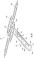
- FIG. 5 is a front perspective view of a base station antenna comprising angled feed stalks according to embodiments of the present invention.
- FIG. 6 A is a partial, simplified front view of a base station antenna (shown without the radome) that includes lower-band radiating elements that have angled feed stalks according to embodiments of the present invention.
- FIG. 6 B is a simplified section view of the base station antenna shown in FIG. 6 A (shown with the radome).
- FIG. 6 C is an active Smith chart of one of the lower-band linear arrays included in the base station antenna shown in FIGS. 6 A and 6 B , as generated by a computational model.
- FIG. 6 D is a graph of the azimuth pattern for an antenna beam generated by one of the lower-band linear arrays included in the base station antenna of FIGS. 6 A and 6 B , as generated by a computational model.
- FIG. 7 A is a partial, simplified front view of a base station antenna (shown without the radome) that includes lower-band radiating elements having vertical feed stalks.
- FIG. 7 B is a simplified section view of the base station antenna shown in FIG. 7 A (shown with the radome).
- FIG. 7 C is an active Smith chart of one of the lower-band linear arrays included in the base station antenna of FIGS. 7 A and 7 B , as generated by a computational model.
- FIG. 7 D is a graph of the azimuth pattern for an antenna beam generated by one of the lower-band linear arrays included in the base station antenna of FIGS. 7 A and 7 B , as generated by a computational model.
- FIG. 8 A is a partial, simplified front view of a base station antenna (shown without the radome) that includes lower-band radiating elements having vertical feed stalks and unbalanced dipole arm.
- FIG. 8 B is a simplified section view of the base station antenna shown in FIG. 8 A (shown with the radome).
- FIG. 8 C is an active Smith chart of one of the lower-band linear arrays included in the base station antenna of FIGS. 8 A and 8 B , as generated by a computational model.
- FIG. 8 D is a graph of the azimuth pattern for an antenna beam generated by one of the lower-band linear arrays included in the base station antenna of FIGS. 8 A and 8 B , as generated by a computational model.
- FIG. 9 A is an enlarged front, side perspective view of an example radiating element with an angled feed stalk according to embodiments of the present invention.
- FIG. 9 B is a side perspective view of a segment of the feed stalk shown in FIG. 9 A .
- FIG. 9 C is a greatly enlarged lower end view of the feed stalk shown in FIG. 9 B .
- FIG. 10 is a front perspective view of another example embodiment of a radiating element with an angled feed stalk according to embodiments of the present invention.
- FIG. 11 is a side perspective view of another example embodiment of a radiating element with an angled feed stalk according to embodiments of the present invention.
- FIG. 12 is a partial bottom perspective view of a radiating element with an angled feed stalk according to embodiments of the present invention.
- FIG. 13 is a top perspective view of another embodiment of a radiating element with an angled feed stalk according to embodiments of the present invention.
- FIG. 14 is a greatly enlarged partial view of the top of the radiating element with the angled feed stalk shown in FIG. 13 .
- FIG. 15 A is a top view of a radiating element with angled feed stalk according to embodiments of the present invention.
- FIG. 15 B is a side perspective view of the radiating element with angled feed stalk shown in FIG. 15 A .
- FIG. 16 A is an enlarged side view of the radiating element with angled feed stalk shown in FIG. 15 A .
- FIG. 16 B is an enlarged side view of the radiating element with angled feed stalk, taken at 90 degrees from the view shown in FIG. 16 A .
- FIG. 16 C is an enlarged side view of the radiating element with angled feed stalk opposite to the side shown in FIG. 16 A .
- FIG. 16 D is an enlarged side view of the radiating element with angled feed stalk opposite to the side shown in FIG. 16 B .
- FIG. 16 E is a bottom view of the radiating element with angled feed stalk shown in FIG. 15 A .
- FIG. 17 A is a rear, partially exploded view of an example base station antenna comprising the radiating elements with angled feed stalks according to embodiments of the present invention.
- FIG. 17 B is an assembled view of the device shown in FIG. 17 A .
- FIG. 18 A is a partial, front perspective view (without the radome) of the base station antenna shown in FIGS. 17 A, 17 B .
- FIG. 18 B is a simplified section view of the base station antenna shown in FIG. 18 A illustrating split cooperating reflectors according to embodiments of the present invention.
- a base station antenna 100 can include a first linear array 120 - 1 of radiating elements 122 , a second linear array 120 - 2 of radiating elements 122 , and a massive MIMO array 140 of radiating elements 145 .
- the base station antenna 100 has a front 100 f with a radome 111 , a rear 100 r and a reflector 112 .
- the radiating elements 122 , 145 face the radome 111 at the front 100 f of the base station antenna 100 .
- the radiating elements 122 of the first linear array 120 - 1 are arranged in a first column and the radiating elements 122 of the second linear array 120 - 2 are arranged in a second column that is laterally spaced apart from the first column.
- the radiating elements 145 of the massive MIMO array 140 can be arranged in vertically-offset columns as is well known to those of skill in the art.
- the massive MIMO array 140 can be a massive MIMO high-band array.
- the first and second linear arrays 120 - 1 , 120 - 2 can be low-band linear arrays.
- the base station antenna 10 can have a maximal width that is about 500 mm, in some embodiments ( FIG. 5 ) to meet commercially acceptable configurations. However, other widths may be used.
- the massive MIMO array 140 can be positioned adjacent an upper portion segment 100 t of the base station antenna 100 , laterally between the first and second linear arrays 120 - 1 , 120 - 2 on reflector 112 and/or adjacent and cooperating reflector 112 a and/or 212 .
- the linear arrays 120 - 1 , 120 - 2 can include low-band radiating elements 122 according to embodiments of the present invention.
- the low-band radiating elements 122 may comprise cross-dipole radiating elements that include a total of four dipole arms 122 a .
- the low-band radiating elements 122 may be cloaked low-band radiating elements that are configured to be substantially transparent to RF energy in the operating frequency band of the massive MIMO array.
- the base station antenna 100 may include the same general types of arrays of radiating elements as the conventional base station antenna 10 of FIGS. 1 and 2 .
- the conventional base station antenna 10 includes radiating elements 22 that have a feed stalk 21 that is vertical (in the orientation shown in FIG. 2 , outwardly projecting from the reflector 12 in a use orientation). Stated differently, the feed stalk 21 is perpendicular to the reflector 12 and the radome 11 of the base station antenna 10 .
- the feed stalk 21 is positioned laterally inward to one or more columns of the radiating elements 42 of the massive MIMO array 40 to avoid interference between the dipole arm 22 a of the radiating elements 22 and the side surfaces of the radome 11 .
- an unbalanced dipole arm 22 A may be used to position the feed stalk 21 further away from the laterally extending center line of the base station antenna 10 ( FIG. 8 B ), this may undesirably degrade the front-to-back ratio (FBR) performance of the base station antenna and/or isolation between adjacent columns of radiating elements.
- FBR front-to-back ratio
- low-band radiating elements 122 are provided that include “tilted” or “angled” feed stalks 310 that can have at least one segment that extends at an oblique angle from the reflector 112 .
- a first end 311 of the feed stalk 310 of each low-band radiating element 122 can be positioned laterally spaced apart from the outermost radiating element 145 of the massive MIMO array 140 and can reside at a right side 112 r or a left side 1121 of the reflector 112 .
- Each feed stalk 310 can be configured to extend outward and position the opposing second end portion 312 thereof at a position that is laterally inward from the first end portion 311 .
- a feed circuit 315 on the feed stalk 310 comprises RF transmission lines that are used to pass RF signals between the dipole arms 122 a of the cross-dipole radiating elements 122 and a feed network of a base station antenna 100 .
- the feed stalk 310 may also be used to mount the dipole arms 122 a at an appropriate distance in front of the reflector 112 of base station antenna 100 , which is often approximately 3/16 to 1 ⁇ 4 of an operating wavelength.
- the “operating wavelength” refers to the wavelength corresponding to the center frequency of the operating frequency band of the radiating element 122 .
- the low-band radiating elements 122 may (but need not be) mounted on a plurality of feed board 112 b printed circuit boards. Each feed board 112 b may comprise a feed network 112 n and be mounted to extend parallel to the reflector 112 and may have one or more radiating elements 122 mounted thereon.
- the dipole radiator arms 122 a extend in a plane that is substantially parallel to the plane defined by an underlying reflector 112 .
- the radiating elements 122 of the first and second arrays 120 - 1 , 120 - 2 may be designed, for example, to operate in some or all the 617-960 MHz frequency band.
- the feed circuit 315 typically comprises a hook balun 315 b provided on the feed stalk 310 .
- the feed stalk 310 can have at least one angled segment 313 that starts at a location above the reflector 112 (in the orientation of FIG. 3 ) and that is laterally inward of the inner (lower) end portion 311 of the feed stalk 310 .
- the feed stalk can have at least one angled segment that can be angled at an angle ⁇ relative to the reflector 112 , with ⁇ being in a range of about 30 to about 120 degrees.
- the RF transmission line on the feed stalk 310 is used to pass RF signals between the feed board 112 b (or some other RF transmission line of the feed network) and the dipole arms 122 a .
- the position, configuration and/or an area of the feed stalk 310 with the hook balun 315 b can be configured to provide a desired impedance in order to impedance match the RF transmission line on the feed stalk 310 to the impedances of the RF transmission line of the feed network and the dipole arms 122 a.
- the feed stalk 310 can have a total length that is greater than a straight line distance taken between a center 122 c of the dipole arms 122 a and the reflector 112 .
- the angle ⁇ of the at least one angled segment 313 of the feed stalk 310 is in a range of about 30-60 degrees, and the feed stalk 310 extends at this angle ⁇ for greater than half an overall length of the feed stalk 310 .
- This angle ⁇ can be constant over the entire length of the feed stalk 310 before merging into the first and second end portions 311 , 312 .
- the first and second end portions 311 , 312 can both be perpendicular to the reflector 112 .
- the second end portion 312 can couple to the dipole arms 122 a of the radiating elements 122 at a medial location(s) to be balanced or centered with respect to the radiating element 122 with the dipole arms 122 a .
- the second end portion 312 can define a balanced arm (the dipole radiators defining the arms 122 a have a cumulative laterally extending width and the second end portion 312 resides has a symmetric configuration and is centered with respect to the center 122 c of the radiating element/printed circuit board 1122 forming same).
- the term “balanced” arm refers to a symmetrical arm structure with four sides of the same structure.
- the feed stalk 310 preferably has at least have a symmetrical structure on the horizontal side and vertical side or have a symmetrical structure on the ⁇ 45 direction and +45 direction.
- FIG. 4 A schematically illustrates a feed stalk 310 ′ pursuant to further embodiments of the present invention.
- the vertical segment 310 v merges into first and second angled segments 313 1 , 313 2 both residing above the reflector 112 to position the second end portion 312 of the feed stalk 310 ′ laterally inward relative to the first end portion 311 of the feed stalk 310 ′.
- the first angled segment 313 1 has an angle ⁇ 2 that is about 90 degrees from the vertical segment 310 v to be substantially parallel with the reflector 112 .
- the second angled segment 313 2 can extend at an angle ⁇ 3 that is about 90 degrees from the first angled segment 313 1 to be perpendicular to the reflector 112 and substantially parallel to the vertical segment 310 v.
- FIG. 4 B schematically shows a feed stalk 310 ′′ according to further embodiments of the present invention.
- the first angled segment 313 1 resides at an angle si for a sub-distance of the feed stalk 310 ′′ before merging into an intermediate segment 313 i (that is substantially parallel to the reflector 112 ) before merging into the second angled segment 313 2 .
- the second angled segment 313 2 can reside at an angle ⁇ from the reflector 112 or the intermediate segment 313 i that is between 80-120 degrees.
- the intermediate segment 313 i can reside at an angle ⁇ 2 from the first angled segment 313 1 . In some embodiments, ⁇ 2 can be greater than ⁇ 1 and ⁇ 3 .
- FIG. 4 C illustrates that the feed stalk 310 ′′′ can be configured to have the first end portion 311 to project inwardly relative to a side wall 100 s of the base station antenna 100 .
- the feed stalk 310 ′′′ can have a segment that is orthogonal to the reflector 112 .
- the feed stalk 310 ′′′ can have an angled inward configuration to position the radiating element 122 at a desired location in front of the reflector 112 .
- the first end portion 311 can project laterally inward from a feed board 112 b that can be parallel to the side wall 100 s of the base station antenna 100 .
- the first end portion 311 can be coupled to a side wall 112 s of the reflector 112 that is perpendicular to a primary surface of the reflector.
- FIG. 4 D illustrates that the feed stalk 310 ′′′′ can be configured to have the first end portion 311 that is similar to FIG. 4 C but sits lower on the reflector side wall 112 s to allow a shorter reflector side wall 112 s and/or outer housing side wall 100 s .
- the feed stalk 310 ′′′′ projects inwardly relative to a side wall 100 s of the base station antenna 100 .
- the feed stalk 310 ′′′′ can have a segment that is orthogonal to the reflector 112 .
- the first end portion 311 of the feed stalk 310 ′′′′ can be coupled directly or indirectly to the side wall 100 s .
- the first end portion 311 of the feed stalk 310 ′′′′ can be coupled to the reflector side wall 112 s that is adjacent the housing/outer side wall 100 s.
- FIG. 5 illustrates an example base station antenna 100 that may include a massive MIMO array 140 and first and second arrays 120 - 1 , 120 - 2 of radiating elements 122 that include feed stalks according to any of the embodiments of the present invention disclosed herein.
- the massive MIMO array 140 is positioned closer to the top 100 t of the base station antenna 100 than the bottom 100 b .
- the massive MIMO array 140 can comprise high band radiating elements.
- FIGS. 6 A and 6 B are simplified partial front view and a simplified section view of the base station antenna 100 with linear arrays 120 - 1 , 120 - 2 of radiating elements 122 that have the angled feed stalks 310 discussed that are above with reference to FIG. 3 .
- FIG. 6 B illustrates a spacing of 416 mm between centers of corresponding first end portions 311 of feed stalks 310 in the first and second arrays 120 - 1 , 120 - 2 .
- FIG. 6 C illustrates an active Smith chart of this embodiment as computed by a computational model.
- FIG. 6 D illustrates the azimuth pattern of the antenna beam with an appended summary of resultant performance parameters, as computed by a computational model.
- the low-band linear arrays exhibit directivity or gain of 12.6 dB, squint of 1.3°+/ ⁇ 5.3; a 3 dB azimuth beamwidth of 70° at the center frequency of the operating frequency band and about 65° to 80° over the full operating frequency band; a front-to-back ratio of 20 dB; cross polarization ratio for an antenna beam that is not scanned from boresight of 20 dB; cross polarization ratio for an antenna beam that is scanned 600 from boresight of 10 dB; Ele Self ISO: 30; ELE col ISO: 18.
- the term “Ele Self ISO” refers to the cross polarization isolation between the elements.
- ELE col ISO refers to the isolation between the elements in different columns.
- FIGS. 7 A and 7 B are a simplified partial front view and a simplified section view of the conventional base station antenna 10 that includes linear arrays 20 - 1 , 20 - 2 of radiating elements 22 that have vertical feed stalks 21 such as shown in FIG. 2 .
- FIG. 7 B illustrates a spacing of 270 mm between centers of corresponding first end portions of feed stalks 21 in the first and second arrays 120 - 1 , 120 - 2 (much closer than FIG. 6 B ).
- FIG. 7 C illustrates an active Smith chart of this embodiment as computed by a computational model.
- FIG. 7 D illustrates the azimuth pattern of the antenna beam with an appended summary of resultant performance parameters, as computed by a computational model.
- the low-band linear arrays with conventional radiating elements 22 having vertical feed stalks 21 exhibit directivity (gain) of 12.6 dB, squint of 2.8°+/ ⁇ 3.5°; a 3 dB azimuth beamwidth of 71° at the center frequency of the operating frequency band and about 66° to 83° over the full operating frequency band; a front-to-back ratio of 20 dB; cross polarization ratio for an antenna beam that is not scanned from boresight of 28 dB; cross polarization ratio for an antenna beam that is scanned 60° from boresight of 12 dB; Ele Self ISO: 30; ELE col ISO: 15. Thus, the Ele col. ISO is less than the feed stalk shown in FIG. 6 B .
- the feed stalk 310 provides improved isolation between adjacent columns.
- FIGS. 8 A and 8 B are a simplified partial front view and a simplified section view of a base station antenna 10 with linear arrays 120 - 1 , 120 - 2 of radiating elements 122 that have vertical stalks 210 and unbalanced dipole arms 122 a .
- FIG. 8 B illustrates a spacing of 361 mm between centers of first end portions of corresponding feed stalks 210 in the first and second arrays 120 - 1 , 120 - 2 (closer than FIG. 6 B but further than FIG. 7 B ).
- FIG. 8 C illustrates an active Smith chart of this embodiment as computed by a computational model.
- FIG. 8 D is an azimuth pattern of the antenna beam with an appended summary of resultant performance parameters, as computed by a computational model.
- the low-band linear arrays with radiating elements 122 having vertical feed stalks 210 and unbalanced dipole arms 122 a exhibit directivity (gain) of 12.2 dB, squint of 5.2°+/ ⁇ 6.5°; a 3 dB azimuth beamwidth of 73° at the center frequency of the operating frequency band and about 67° to 83° over the full operating frequency band; a front-to-back ratio of 16.2 dB; cross polarization ratio for an antenna beam that is not scanned from boresight of 27 dB; cross polarization ratio for an antenna beam that is scanned 600 from boresight of 8 dB; Ele Self ISO: 23; ELE col ISO: 18.
- the Ele Self ISO is less and the directivity, squint and front-to-back ratio are worse than that of the feed stalk shown in FIG. 6 B .
- the angled feed stalk 310 comprises a plurality of cooperating formed sheet metal legs 1310 , each having a self-supporting shape.
- Each sheet metal leg 1310 can have a primary body segment 1310 b that extends at an angle ⁇ that is in a range of about 30-75 degrees for at least a major portion of its length between opposing first and second end portions, 1311 , 1312 , respectively.
- the first end portions 1311 can collectively define the first end portion 311 of the feed stalk 310 .
- the second end portions 1312 can be coupled to a printed circuit board 1122 ( FIG.
- the second end portions 1312 of the sheet metal components 1310 can collectively define the second end portion 312 of the feed stalk 310 .
- the first end portions 1311 can all be orthogonal to the reflector 112 and can be coupled to the reflector 112 and/or feed board 112 b and may be electrically connected to the feed network for the low-band linear array 120 .
- the first end portions 1311 of the sheet metal legs 1310 can be secured to reside on, extend down into or below the reflector 112 .
- the first end portions 1311 of the feed stalk 310 can be soldered to the feed board 112 b without the use of slots through the feed board 112 b in some embodiments.
- the sheet metal legs 1310 can provide a cost-effective manufacturing for providing the formed shapes of the feed stalk 310 over using printed circuit boards alone and may provide easier assembly for desired tolerances.
- the feed stalk 310 can have a narrower extent when using the PCB microstrip (MS) line for the circuit 315 .
- MS PCB microstrip
- the feed stalk 310 has four cooperating sheet metal legs 1310 1 - 1310 4 . At least some of the sheet metal legs 1310 can provide part of the feed circuit 315 forming the balun(s) 315 b.
- the feed circuit 315 includes a pair of RF transmission lines or traces 315 t that are used to pass RF signals between the feed network and the dipole arms 122 a .
- the RF transmission lines 315 t are formed using printed circuit boards 1315 that are coupled to one or more of the formed sheet metal legs 1310 .
- Each printed circuit board 1315 comprises a dielectric substrate that includes a metal trace 315 t that is opposite the sheet metal leg on which the printed circuit board 1315 is mounted.
- Each printed circuit board 1315 can be planar and/or conformal to a primary surface of the sheet metal leg 1310 .
- the traces 315 t of the feed circuit 315 can be straight, meandering and/or curvilinear.
- the printed circuit boards 1315 can have any outer perimeter shape such as square, rectangular, triangular or oval.
- the printed circuit boards 1315 may have a metallized back surface that is maintained at ground potential or can be devoid of a metallized back surface and use the sheet metal legs 1310 as the ground plane for the microstrip transmission line.
- the printed circuit boards 1315 can be flexible, rigid or semi-rigid printed circuit boards.
- the term “semi-rigid” means that the printed circuit board has sufficient rigidity to define a self-supporting shape.
- the feed stalk 310 can include first and second printed circuit boards 1315 1 , 1315 2 that are each coupled to at least one sheet metal leg 1310 .
- the first and second printed circuit boards 1315 1 , 1315 2 are arranged to be orthogonal to each other, with one crossing over the other.
- each of the first and second printed circuit boards 1315 1 , 1315 2 may include a cross-segment 1315 c with a continuation of the conductive trace 315 t that extends along both pairs 1310 p of sheet metal legs 1310 and that spans an open gap space between pairs 1310 p of the sheet metal legs 1310 .
- one or both of the first and second printed circuit boards 1315 1 , 1315 2 can terminate above the reflector 112 .
- One or both of an end portion 1315 e of the first and second printed circuit boards 1315 1 , 1315 2 can be coupled to a conductive (e.g., metal) feed member 1317 that can be used to connect the trace 315 t of the feed circuit 315 to an RF transmission line on the reflector/feed board 112 b or to a different feed (e.g., to a center conductor of a coaxial cable feed).
- a coaxial cable can be used and/or the conductive feed member 1317 can be extended to connect the feed board circuit.
- a coaxial cable can be used to connect to the power divider of phase shifter circuit.
- the connection configurations/types can vary depending on the network design.
- the conductive feed member 1317 may have an “L” shape and have an end portion 1317 e that is perpendicular to the reflector 112 .
- a gasket 1319 which can be rectangular as shown, and can be electrically non-conductive, can be positioned between a lower end portion 1311 of a respective sheet metal leg 1310 and the end portion 1315 e of the printed circuit board 1315 used to guide/support the lower end of the feed member 1317 .
- the printed circuit board 1315 and conductive feed member 1317 can be coupled together, such as capacitively coupled or soldered or otherwise.
- a second printed circuit board 2315 directly provides at least one leg of the feed stalk 310 without being coupled to an underlying sheet metal leg.
- the end portion 2315 e of the second printed circuit board 2315 can be perpendicular to the reflector 112 .
- the second printed circuit board 2315 can cooperate with at least one spaced apart cooperating sheet metal leg 1310 .
- the second printed circuit board 2315 can be thicker than the first printed circuit board 1315 coupled to the at least one sheet metal leg 1310 .
- the second printed circuit board 2315 can comprise a trace 315 t of the feed circuit 315 and that trace 315 t can be straight, meandering and/or curvilinear.
- the second printed circuit board 2315 can have any outer perimeter shape such as square, rectangular, triangular or oval.
- the first printed circuit board 1315 can reside on two spaced apart sheet metal legs 1310 and can include a cross-segment 1315 c with a continuation of the conductive trace 315 t that extends along both sheet metal legs 1310 and that spans an open gap space between a cooperating pair of the sheet metal legs 1310 .
- the second printed circuit board 2315 can have one or more slots 2315 s that receive a respective cross-segment 1313 of the sheet metal legs 1310 .
- the cross-segments 1313 may be used to mount the second printed circuit board 2315 in a desired position.
- the first and second printed circuit boards 1315 , 2315 can each have a respective hook balun 315 b , one for each polarization.
- Cooperating pairs of the sheet metal legs 1310 comprising a respective printed circuit board 1315 can be provided as a unitary body or separate components.
- the outer end 2317 of the second printed circuit board 2315 can provide two spaced apart end segments 2317 1 , 2317 2 , on opposing sides of a center 122 c of the radiating element 122 (a center between the dipole arms 122 a ).
- the second end portion 1312 of each sheet metal leg 1310 of the pair of cooperating sheet metal legs 1310 p can be configured to reside on opposing sides of the center 122 c, 90 degrees offset from the end segments 2317 1 , 2317 2 of the printed circuit board 2315 .
- the printed circuit board 1315 with trace 315 t that is coupled to the sheet metal leg(s) 1310 may or may not include an electrical ground layer opposite the trace 315 t .
- an electrical ground can be applied to the rear surface of the printed circuit board 1315 and/or the sheet metal leg 1310 and can be used as the electrical ground layer.
- the second end portions 1312 of the sheet metal legs 1310 can be attached to a medial portion of the printed circuit board 1122 of the radiating element 1122 that provides the dipole arms 122 a .
- the RF transmission lines 315 t on the feed stalk 310 can be capacitively coupled to the dipole arms 122 a of the radiating element 122 .
- the second end portions 1312 of the pair 1310 of cooperating sheet metal legs 1310 and the first and second ends 2317 1 , 2317 2 of the second printed circuit board 2315 can be attached to a medial portion of the printed circuit board 1122 of the radiating element 122 that provides the dipole arms 122 a .
- the apertures 1128 are arranged so that the two spaced apart end segments 2317 1 , 2317 2 , are aligned but on opposing sides of a center 122 c of the radiating element 122 (a center between the dipole arms 122 a ).
- the projecting outer ends 1312 p of the second end portions 1312 of the cooperating sheet metal legs 1310 p are also aligned and reside on opposing sides of the center 122 c, 90 degrees offset from the end segments 2317 1 , 2317 2 of the second printed circuit board 2315 .
- the projecting edges 2317 p , 1312 p can be soldered to the radiating element 122 providing the dipole arms 122 a and provide a galvanic feed instead of a capacitive feed in this embodiment.
- the radiating element 122 comprises a feed stalk 310 coupled to the printed circuit board 1122 providing the radiating dipole arms 122 a .
- the feed stalk 310 comprises the second printed circuit board 2315 and one pair 1310 p of cooperating sheet metal legs 1310 with the first printed circuit board 1315 .
- the feed stalk 310 can also include coupling members 1600 that attach the first printed circuit board 1315 to the sheet metal legs 1310 .
- the coupling members 1600 can comprise rivets fixing the 1315 to the metal stalk leg(s) 1310 .
- the projecting (outer) edges 1312 p , 1217 p extend outward from the printed circuit board 1122 through apertures 1128 and can be soldered to the printed circuit board 1122 .
- Cross-segments 1313 under the printed circuit board 1122 can be coupled to or defined by (e.g., tabs) of the sheet metal legs 1310 and can be coupled to and/or extend to or through the second printed circuit board 2135 .
- the base station antenna 100 comprises the first and second linear arrays 120 - 1 , 120 - 2 and can be configured to sealably receive an active antenna module 110 that comprises the massive MIMO antenna array 140 .
- the base station antenna 100 has a cavity 155 that receives a forward-facing segment of the active antenna module 110 .
- the active antenna module 110 can extend at a top portion of the base station antenna 100 , closer to the top than the bottom 100 b .
- the active antenna module 110 can comprise a rear 110 r with a heat sink 115 with external fins 115 f and brackets 118 .
- active antenna module refers to an integrated cellular communications unit comprising a remote radio unit (RRU) and associated antenna elements that is capable of electronically adjusting the amplitude and/or phase of the subcomponents of an RF signal that are output to different antenna elements or groups thereof.
- the active antenna module 110 comprises the RRU and antenna but may include other components such as a filter, a, calibration network, a controller and the like.
- the active antenna module 110 can have an outer perimeter 110 p with an inner facing seal interface.
- the reflector 112 can be provided as a split reflector configuration comprising first and second capacitively coupled reflectors 112 f , 112 a , respectively.
- the first reflector 112 f is a fixed reflector that resides in the base station antenna housing 100 h and includes segments under/behind the feed stalks 310 , 310 ′, 310 ′′ of the low band radiating elements 120 - 1 , 120 - 2 .
- the second reflector 112 a is coupled to the multi-column array 140 and resides in the removable active antenna module 110 .
- the reflector 112 f of the passive antenna assembly in the base station antenna 100 typically comprises a sheet of metal or a frequency selective surface and is maintained at electrical ground. See, e.g., U.S. Provisional Patent Application Ser. No. 63/136,757, the contents of which are hereby incorporated by reference as if recited in full herein.
- a reflector 112 such as the first or second reflector 112 f , 112 a , respectively, can comprise a frequency selective surface can reside behind at least some antenna elements and can selectively reject some frequency bands and permit other frequency bands to pass therethrough by including the frequency selective surface and/or substrate to operate as a type of “spatial filter”. See, e.g., Ben A.
- the reflector 112 f can act to redirect RF radiation that is emitted backwardly by the radiating elements in the forward direction, and also serves as a ground reference for the radiating elements.
- the reflector 112 a of the active antenna module 110 is coupled, upon assembly to the base station antenna housing 100 h , to the reflector 112 f so that the reflectors 112 a , 112 f are at a common electrical ground reference.
- the active antenna reflector 112 a can be spaced apart from the reflector 112 f (in a front to back direction) about a small gap space that is typically in a range of about 3 mm-about 10 mm, in some embodiments. As shown in FIG.
- the base station antenna 100 may also include at least one internal radome 119 residing over the multi-column array 140 and which is part of the active antenna module 110 .
- the base station antenna may optionally also include an intermediate radome 1129 that resides between the outer radome 111 and the internal radome 119 .
- active antenna modules 110 and cooperating (e.g., split) reflectors for base station antennas 100 see, co-pending, co-assigned U.S. Provisional Application Ser. No. 63/082,265, filed Sep. 23, 2020, and the contents of which are hereby incorporated by reference as if recited in full herein.
- the radiating elements 122 of the first and second linear arrays 120 - 1 , 120 - 2 can also be interchangeably referred to as a “dual polarized radiators” with first and second dipole radiators having first, second, third and fourth dipole arms 122 a.
- the radiating elements 122 can reside in front of the two reflectors 112 f , 112 a and can operate with both reflectors as a portion of a respective radiating element 122 can reside in front of the first reflector 112 f while another portion of the respective radiating element 122 can reside in front of the other reflector 112 a .
- the two different reflectors can be adjacently positioned, optionally laterally spaced apart and longitudinally extending reflectors.
- adjacent segments of the first and second reflectors 112 f , 112 a can be separated by a radome 119 and/or 1129 therebetween.
- the radome 119 and/or 1129 and/or air gap spaces provided by same can define a dielectric for capacitively coupling the reflectors 112 f , 112 a.
- the first and second dipole radiators may be configured to transmit RF radiation having slant ⁇ 45° and slant +45° polarization.
- These radiating elements may be particularly well-suited for use in base station antennas that have a multi-column array 140 of radiating elements 145 that operate in a higher frequency band than the radiating elements 122 according to embodiments of the present invention.
- the low-band radiating elements 122 may be configured to transmit and receive signals in a first frequency band such as, for example, the 617-960 MHz frequency range or a portion thereof.
- the high-band radiating elements 145 can be mounted in columns to form 4 - 12 linear arrays of high-band radiating elements.
- the multi-column array 140 of high-band radiating elements 145 may be configured to transmit and receive signals in a higher frequency band such as, for example, the 3300-4200 MHz frequency range or a portion thereof or even higher frequency (typically in a 3 GHz-6 GHz range).
- So-called “cloaked” low-band radiating elements have been developed that are designed to be “transparent” to RF signals in the operating frequency band of nearby higher-band radiating elements. See, e.g., one example of a known cloaked dual-polarized low-band radiating element 100 , which is disclosed in U.S. Patent Publication No. 2018/0323513 (“the '513 publication”), filed Feb. 15, 2018, the entire content of which is incorporated herein by reference.
- the radiating element 100 generates both slant ⁇ 45° and slant +45° radiation, and is typically called a “cross-dipole” radiating element as it includes two dipole radiators that form a cross shape when viewed from the front.
- Each dipole arm 122 a may be formed as a metal pattern on printed circuit board 1122 .
- Each metal pattern includes a plurality of widened conductive members that are connected by narrowed trace sections.
- the narrowed trace sections may be implemented as meandered conductive traces.
- a meandered conductive trace refers to a non-linear conductive trace that follows a meandered path to increase the path length thereof.
- the meandered conductive trace sections may have extended lengths yet still have a small physical footprint.
- Each dipole arm 122 a may comprise a loop that includes a series of alternating widened conductive members and narrowed trace sections. Each pair of adjacent widened conductive members may be physically and electrically connected by a respective one of the narrowed trace sections. Since the narrowed trace sections have a small physical footprint, adjacent widened conductive members may be in close proximity to each other so that the widened conductive members together appear as a single dipole arm at frequencies within the operating frequency range of the low-band radiating element 122 . It will be appreciated that in other embodiments, the dipole arms need not have a closed loop design as explained, for example, in the '513 publication (e.g., the distal ends of two segments that form the loop may not be electrically connected to each other).
- Relative terms such as “below” or “above” or “upper” or “lower” or “horizontal” or “vertical” may be used herein to describe a relationship of one element, layer or region to another element, layer or region as illustrated in the figures. It will be understood that these terms are intended to encompass different orientations of the device in addition to the orientation depicted in the figures.
Landscapes
- Engineering & Computer Science (AREA)
- Computer Networks & Wireless Communication (AREA)
- Physics & Mathematics (AREA)
- Electromagnetism (AREA)
- Variable-Direction Aerials And Aerial Arrays (AREA)
- Aerials With Secondary Devices (AREA)
- Details Of Aerials (AREA)
Abstract
Description
Claims (27)
Priority Applications (2)
| Application Number | Priority Date | Filing Date | Title |
|---|---|---|---|
| US17/205,122 US11652300B2 (en) | 2020-03-24 | 2021-03-18 | Radiating elements having angled feed stalks and base station antennas including same |
| US18/048,085 US11909121B2 (en) | 2020-03-24 | 2022-10-20 | Radiating elements having angled feed stalks and base station antennas including same |
Applications Claiming Priority (3)
| Application Number | Priority Date | Filing Date | Title |
|---|---|---|---|
| US202062993925P | 2020-03-24 | 2020-03-24 | |
| US202063087451P | 2020-10-05 | 2020-10-05 | |
| US17/205,122 US11652300B2 (en) | 2020-03-24 | 2021-03-18 | Radiating elements having angled feed stalks and base station antennas including same |
Related Child Applications (1)
| Application Number | Title | Priority Date | Filing Date |
|---|---|---|---|
| US18/048,085 Continuation US11909121B2 (en) | 2020-03-24 | 2022-10-20 | Radiating elements having angled feed stalks and base station antennas including same |
Publications (2)
| Publication Number | Publication Date |
|---|---|
| US20210305718A1 US20210305718A1 (en) | 2021-09-30 |
| US11652300B2 true US11652300B2 (en) | 2023-05-16 |
Family
ID=77857244
Family Applications (2)
| Application Number | Title | Priority Date | Filing Date |
|---|---|---|---|
| US17/205,122 Active US11652300B2 (en) | 2020-03-24 | 2021-03-18 | Radiating elements having angled feed stalks and base station antennas including same |
| US18/048,085 Active US11909121B2 (en) | 2020-03-24 | 2022-10-20 | Radiating elements having angled feed stalks and base station antennas including same |
Family Applications After (1)
| Application Number | Title | Priority Date | Filing Date |
|---|---|---|---|
| US18/048,085 Active US11909121B2 (en) | 2020-03-24 | 2022-10-20 | Radiating elements having angled feed stalks and base station antennas including same |
Country Status (8)
| Country | Link |
|---|---|
| US (2) | US11652300B2 (en) |
| EP (1) | EP3939119A4 (en) |
| CN (2) | CN115693182A (en) |
| AU (1) | AU2021242222A1 (en) |
| CA (1) | CA3172688A1 (en) |
| DE (1) | DE202021106120U1 (en) |
| MX (1) | MX2022011745A (en) |
| WO (1) | WO2021194832A1 (en) |
Cited By (1)
| Publication number | Priority date | Publication date | Assignee | Title |
|---|---|---|---|---|
| US20220115760A1 (en) * | 2019-06-28 | 2022-04-14 | Kmw Inc. | Antenna apparatus |
Families Citing this family (10)
| Publication number | Priority date | Publication date | Assignee | Title |
|---|---|---|---|---|
| WO2019010051A1 (en) * | 2017-07-07 | 2019-01-10 | Commscope Technologies Llc | Ultra-wide bandwidth low-band radiating elements |
| KR20220036179A (en) * | 2020-09-15 | 2022-03-22 | 타이코에이엠피 주식회사 | Antenna device |
| US11581631B2 (en) * | 2020-09-25 | 2023-02-14 | Commscope Technologies Llc | Base station antennas having radomes that reduce coupling between columns of radiating elements of a multi-column array |
| CN115224535A (en) * | 2021-04-15 | 2022-10-21 | 康普技术有限责任公司 | Connection device and base station antenna |
| DE102022130301A1 (en) * | 2021-11-25 | 2023-05-25 | Nokia Shanghai Bell Co., Ltd. | COMPACT MODULAR ACTIVE-PASSIVE ANTENNA SYSTEMS WITH MINIMIZED ANTENNA BLOCKAGE |
| DE102022100620A1 (en) | 2022-01-12 | 2023-07-13 | Hahn-Schickard-Gesellschaft für angewandte Forschung e.V. | SENSORY CLAPPER FOR WIRELESS ADAPTIVE VOLTAGE CONTROL FOR MATERIAL-SPECIFIC PROCESS DESIGN |
| WO2023155973A1 (en) | 2022-02-15 | 2023-08-24 | Telefonaktiebolaget Lm Ericsson (Publ) | Antenna system with radiating element fed via side region |
| WO2023215567A1 (en) * | 2022-05-06 | 2023-11-09 | John Mezzalingua Associates, LLC | Low band dipole with extended bandwidth and improved midband cloaking |
| US20230395971A1 (en) | 2022-06-01 | 2023-12-07 | Commscope Technologies Llc | Passive/active base station antenna systems having passive reflector assemblies with an opening for an active antenna array |
| WO2024011344A1 (en) | 2022-07-11 | 2024-01-18 | Commscope Technologies Llc | Radiating elements having single or parallel printed circuit board-based feed stalks and base station antennas having such radiating elements |
Citations (47)
| Publication number | Priority date | Publication date | Assignee | Title |
|---|---|---|---|---|
| WO1997000586A1 (en) | 1995-06-16 | 1997-01-03 | Nokia Telecommunications Oy | Method and apparatus for establishing a test loop for monitoring the operation of a radio station |
| EP1204161A1 (en) | 1999-08-10 | 2002-05-08 | China Academy of Telecommunications Technology, MII | Method and apparatus for calibrating smart antenna array |
| US20040169612A1 (en) | 2003-02-28 | 2004-09-02 | Song Peter Chun Teck | Multiband branch radiator antenna element |
| US20040259597A1 (en) | 1998-09-21 | 2004-12-23 | Gothard Griffin K. | Adaptive antenna for use in wireless communication systems |
| US20050264463A1 (en) | 2004-05-27 | 2005-12-01 | Kathrein-Werke Kg | Stationary mobile radio antenna |
| US20060273865A1 (en) * | 2005-06-02 | 2006-12-07 | Timofeev Igor E | Dipole antenna array |
| US20070229385A1 (en) | 2006-03-30 | 2007-10-04 | Gang Yi Deng | Broadband dual polarized base station antenna |
| WO2009061966A1 (en) * | 2007-11-09 | 2009-05-14 | Powerwave Technologies, Inc. | Variable stagger reflector for azimuth beam width controlled antenna |
| CN100492763C (en) * | 2002-06-19 | 2009-05-27 | 安德鲁公司 | Single piece twin folded dipole antenna |
| US20090135076A1 (en) * | 2007-11-28 | 2009-05-28 | Senglee Foo | Linear antenna array with azimuth beam augmentation by axial rotation |
| US20090224994A1 (en) | 2003-06-26 | 2009-09-10 | Kevin Le | Directed dual beam antenna |
| CN201528038U (en) | 2009-07-30 | 2010-07-14 | 京信通信系统(中国)有限公司 | Integrated antenna and integrated radio frequency device |
| CN101950846A (en) | 2010-09-03 | 2011-01-19 | 广东通宇通讯设备有限公司 | Active integrated antenna system |
| US7907096B2 (en) | 2008-01-25 | 2011-03-15 | Andrew Llc | Phase shifter and antenna including phase shifter |
| CN201893434U (en) | 2010-11-22 | 2011-07-06 | 南京恩瑞特实业有限公司 | Embedded type active integrated antenna |
| US20120087284A1 (en) | 2010-10-08 | 2012-04-12 | Andrew Llc | Antenna Having Active And Passive Feed Networks |
| US20120280874A1 (en) | 2009-12-21 | 2012-11-08 | In-Ho Kim | Reconfigurable base station antenna |
| CN102800956A (en) | 2012-08-18 | 2012-11-28 | 哈尔滨工业大学(威海) | Wideband dual-polarized antenna for integrated balun feed |
| US20130234883A1 (en) | 2012-02-24 | 2013-09-12 | Futurewei Technologies, Inc. | Apparatus and Method for an Active Antenna System with Near-field Radio Frequency Probes |
| CN103490175A (en) | 2013-09-23 | 2014-01-01 | 摩比天线技术(深圳)有限公司 | Integrated base station antenna |
| CN103715521A (en) | 2012-10-08 | 2014-04-09 | 华为技术有限公司 | Active-passive integrated antenna apparatus and base station |
| EP2784876A1 (en) | 2011-12-13 | 2014-10-01 | Huawei Technologies Co., Ltd | Antenna device, base station, and communication system |
| EP2827449A2 (en) | 2012-03-20 | 2015-01-21 | Huawei Technologies Co., Ltd. | Antenna device and system |
| CN104319486A (en) | 2014-10-14 | 2015-01-28 | 西安电子科技大学 | Reflecting plate based on ultra-wide stopband frequency selective surface |
| US20150084823A1 (en) | 2012-05-29 | 2015-03-26 | Huawei Technologies Co., Ltd. | Dual-polarized antenna radiating element and base station antenna |
| US20150097739A1 (en) | 2008-06-24 | 2015-04-09 | George Samuel | Wideband High Gain Antenna for Multiband Employment |
| US20160365618A1 (en) | 2014-02-24 | 2016-12-15 | Kmw Inc. | Multi-band antenna apparatus |
| US20170040679A1 (en) | 2014-01-23 | 2017-02-09 | Kathrein-Werke Kg | Mobile radio antenna |
| CN206225553U (en) | 2016-11-23 | 2017-06-06 | 京信通信技术(广州)有限公司 | Bipolar radiator, antenna assembly and base station system |
| US20180269577A1 (en) | 2015-09-29 | 2018-09-20 | Nec Corporation | Multiband antenna and wireless communication device |
| US20180323513A1 (en) | 2017-05-03 | 2018-11-08 | Commscope Technologies Llc | Multi-band base station antennas having crossed-dipole radiating elements with generally oval or rectangularly shaped dipole arms and/or common mode resonance reduction filters |
| CN109219905A (en) | 2017-01-24 | 2019-01-15 | 康普技术有限责任公司 | Antenna for base station including supplementing array |
| WO2019100325A1 (en) | 2017-11-24 | 2019-05-31 | 华为技术有限公司 | Uplink signal transmission method, base station, and system |
| US20190173162A1 (en) | 2017-12-06 | 2019-06-06 | Galtronics Usa, Inc. | Antenna array |
| US20190181557A1 (en) * | 2014-11-18 | 2019-06-13 | Commscope Technologies Llc | Cloaked low band elements for multiband radiating arrays |
| WO2019154362A1 (en) | 2018-02-06 | 2019-08-15 | 京信通信系统(中国)有限公司 | Multi-standard-integrated antenna |
| US20190267701A1 (en) | 2016-11-16 | 2019-08-29 | Kmw Inc. | Antenna device |
| EP3544204A2 (en) | 2016-11-16 | 2019-09-25 | KMW Inc. | Mimo antenna assembly of laminated structure |
| US20190312394A1 (en) | 2018-04-04 | 2019-10-10 | Commscope Technologies Llc | Ganged coaxial connector assembly |
| US20190312338A1 (en) | 2016-12-06 | 2019-10-10 | Huawei Technologies Co., Ltd. | Dual-band antenna element and base station |
| CN110323564A (en) | 2019-04-30 | 2019-10-11 | 深圳市大富科技股份有限公司 | A kind of active antenna element and antenna element for base station |
| WO2019236203A2 (en) | 2018-05-15 | 2019-12-12 | Commscope Technologies Llc | Base station antennas having fully embedded radios and housings with integrated heat sink structures |
| WO2020010039A1 (en) | 2018-07-05 | 2020-01-09 | Commscope Technologies Llc | Multi-band base station antennas having radome effect cancellation features |
| US20200076079A1 (en) * | 2017-06-15 | 2020-03-05 | Commscope Technologies Llc | Cloaking antenna elements and related multi-band antennas |
| WO2020072880A1 (en) | 2018-10-05 | 2020-04-09 | Commscope Technologies Llc | Reconfigurable multi-band base station antennas having self-contained sub-modules |
| US20210305717A1 (en) | 2020-03-24 | 2021-09-30 | Commscope Technologies Llc | Base station antennas having an active antenna module and related devices and methods |
| CN114094347A (en) | 2020-08-24 | 2022-02-25 | 华为技术有限公司 | Multi-band antenna system and base station |
Family Cites Families (28)
| Publication number | Priority date | Publication date | Assignee | Title |
|---|---|---|---|---|
| JPS6081902A (en) | 1983-10-12 | 1985-05-10 | Nec Corp | High frequency branching filter device |
| FR2649539B1 (en) | 1989-07-06 | 1991-11-08 | Yves Devillers | REMOVABLE AND AEROTRANSPORTABLE ANTENNA FOR TWO-WAY TELECOMMUNICATIONS WITH A SATELLITE |
| DE19627015C2 (en) | 1996-07-04 | 2000-07-13 | Kathrein Werke Kg | Antenna field |
| US5982339A (en) | 1996-11-26 | 1999-11-09 | Ball Aerospace & Technologies Corp. | Antenna system utilizing a frequency selective surface |
| EP0982800A2 (en) | 1998-08-27 | 2000-03-01 | Lucent Technologies Inc. | High frequency delay device using frequency selective surfaces |
| US6388637B1 (en) | 2000-01-21 | 2002-05-14 | Northrop Grumman Corporation | Wide band, wide scan antenna for space borne applications |
| US7427962B2 (en) * | 2003-06-16 | 2008-09-23 | Andrew Corporation | Base station antenna rotation mechanism |
| DE102010024866A1 (en) | 2010-06-24 | 2011-12-29 | Pharmatech Gmbh | Formulation for taste masking |
| WO2011160649A2 (en) | 2010-06-24 | 2011-12-29 | Mohamed Saed Abdelazez Sanad Elgendy | A low wind load lightweight foldable / deployable base station antenna for mobile tv, wimax, cdma and gsm |
| US9276329B2 (en) * | 2012-11-22 | 2016-03-01 | Commscope Technologies Llc | Ultra-wideband dual-band cellular basestation antenna |
| EP3033805B1 (en) | 2013-08-16 | 2017-05-24 | CommScope Technologies LLC | Modular small cell base station architecture |
| US9548544B2 (en) | 2015-06-20 | 2017-01-17 | Huawei Technologies Co., Ltd. | Antenna element for signals with three polarizations |
| CN108370095A (en) | 2015-08-06 | 2018-08-03 | 薄膜电子有限公司 | Wireless communication device and production and preparation method thereof with integrated ferrite shielding and antenna |
| US10790576B2 (en) | 2015-12-14 | 2020-09-29 | Commscope Technologies Llc | Multi-band base station antennas having multi-layer feed boards |
| CN107459805B (en) | 2016-06-06 | 2020-11-24 | 华为技术有限公司 | Base station antenna housing and manufacturing method thereof |
| WO2018177542A1 (en) | 2017-03-31 | 2018-10-04 | Huawei Technologies Co., Ltd. | Reflector for an antenna |
| WO2018180766A1 (en) | 2017-03-31 | 2018-10-04 | 日本電気株式会社 | Antenna, multiband antenna, and wireless communication device |
| US11292166B2 (en) | 2017-04-07 | 2022-04-05 | Tactotek Oy | Method for manufacturing an electronic assembly and an electronic assembly |
| CN107453044A (en) | 2017-07-25 | 2017-12-08 | 重庆邮电大学 | A kind of dual polarization micro-base station mimo antenna unit |
| WO2019126377A1 (en) | 2017-12-19 | 2019-06-27 | Lockheed Martin Corporation | Wide scan phased array fed reflector systems |
| CN215497097U (en) * | 2019-02-01 | 2022-01-11 | 康普技术有限责任公司 | Multiband base station antenna with staggered array |
| CN111786081A (en) * | 2019-04-04 | 2020-10-16 | 康普技术有限责任公司 | Multiband base station antenna with integrated array |
| WO2021150384A1 (en) | 2020-01-08 | 2021-07-29 | Metawave Corporation | Reflectarray antenna with two-dimensional beam scanning |
| CN113140893A (en) | 2020-01-20 | 2021-07-20 | 康普技术有限责任公司 | Compact broadband dual polarized radiating element for base station antenna applications |
| EP4143922A1 (en) | 2020-04-28 | 2023-03-08 | CommScope Technologies LLC | Base station antennas having reflector assemblies including a nonmetallic substrate having a metallic layer thereon |
| US11581631B2 (en) | 2020-09-25 | 2023-02-14 | Commscope Technologies Llc | Base station antennas having radomes that reduce coupling between columns of radiating elements of a multi-column array |
| CN112201939A (en) | 2020-10-12 | 2021-01-08 | 华南理工大学 | Double-frequency fusion antenna based on super surface and communication equipment |
| CN215418610U (en) | 2021-08-31 | 2022-01-04 | 康普技术有限责任公司 | Frequency selective reflector and base station antenna |
-
2021
- 2021-03-18 MX MX2022011745A patent/MX2022011745A/en unknown
- 2021-03-18 EP EP21777118.7A patent/EP3939119A4/en active Pending
- 2021-03-18 US US17/205,122 patent/US11652300B2/en active Active
- 2021-03-18 DE DE202021106120.0U patent/DE202021106120U1/en active Active
- 2021-03-18 CN CN202211451054.0A patent/CN115693182A/en active Pending
- 2021-03-18 AU AU2021242222A patent/AU2021242222A1/en active Pending
- 2021-03-18 CN CN202180003044.8A patent/CN113748572B/en active Active
- 2021-03-18 WO PCT/US2021/022890 patent/WO2021194832A1/en unknown
- 2021-03-18 CA CA3172688A patent/CA3172688A1/en active Pending
-
2022
- 2022-10-20 US US18/048,085 patent/US11909121B2/en active Active
Patent Citations (51)
| Publication number | Priority date | Publication date | Assignee | Title |
|---|---|---|---|---|
| WO1997000586A1 (en) | 1995-06-16 | 1997-01-03 | Nokia Telecommunications Oy | Method and apparatus for establishing a test loop for monitoring the operation of a radio station |
| US20040259597A1 (en) | 1998-09-21 | 2004-12-23 | Gothard Griffin K. | Adaptive antenna for use in wireless communication systems |
| EP1204161A1 (en) | 1999-08-10 | 2002-05-08 | China Academy of Telecommunications Technology, MII | Method and apparatus for calibrating smart antenna array |
| CN100492763C (en) * | 2002-06-19 | 2009-05-27 | 安德鲁公司 | Single piece twin folded dipole antenna |
| US20040169612A1 (en) | 2003-02-28 | 2004-09-02 | Song Peter Chun Teck | Multiband branch radiator antenna element |
| US20090224994A1 (en) | 2003-06-26 | 2009-09-10 | Kevin Le | Directed dual beam antenna |
| US20050264463A1 (en) | 2004-05-27 | 2005-12-01 | Kathrein-Werke Kg | Stationary mobile radio antenna |
| US20060273865A1 (en) * | 2005-06-02 | 2006-12-07 | Timofeev Igor E | Dipole antenna array |
| US20070229385A1 (en) | 2006-03-30 | 2007-10-04 | Gang Yi Deng | Broadband dual polarized base station antenna |
| WO2009061966A1 (en) * | 2007-11-09 | 2009-05-14 | Powerwave Technologies, Inc. | Variable stagger reflector for azimuth beam width controlled antenna |
| US20090135076A1 (en) * | 2007-11-28 | 2009-05-28 | Senglee Foo | Linear antenna array with azimuth beam augmentation by axial rotation |
| US7907096B2 (en) | 2008-01-25 | 2011-03-15 | Andrew Llc | Phase shifter and antenna including phase shifter |
| US20150097739A1 (en) | 2008-06-24 | 2015-04-09 | George Samuel | Wideband High Gain Antenna for Multiband Employment |
| CN201528038U (en) | 2009-07-30 | 2010-07-14 | 京信通信系统(中国)有限公司 | Integrated antenna and integrated radio frequency device |
| US20120280874A1 (en) | 2009-12-21 | 2012-11-08 | In-Ho Kim | Reconfigurable base station antenna |
| CN101950846A (en) | 2010-09-03 | 2011-01-19 | 广东通宇通讯设备有限公司 | Active integrated antenna system |
| US20120087284A1 (en) | 2010-10-08 | 2012-04-12 | Andrew Llc | Antenna Having Active And Passive Feed Networks |
| CN201893434U (en) | 2010-11-22 | 2011-07-06 | 南京恩瑞特实业有限公司 | Embedded type active integrated antenna |
| US20140313095A1 (en) * | 2011-12-13 | 2014-10-23 | Huawei Technologies Co., Ltd. | Antenna apparatus, base station and communications system |
| EP2784876A1 (en) | 2011-12-13 | 2014-10-01 | Huawei Technologies Co., Ltd | Antenna device, base station, and communication system |
| US20130234883A1 (en) | 2012-02-24 | 2013-09-12 | Futurewei Technologies, Inc. | Apparatus and Method for an Active Antenna System with Near-field Radio Frequency Probes |
| EP2827449A2 (en) | 2012-03-20 | 2015-01-21 | Huawei Technologies Co., Ltd. | Antenna device and system |
| US20150084823A1 (en) | 2012-05-29 | 2015-03-26 | Huawei Technologies Co., Ltd. | Dual-polarized antenna radiating element and base station antenna |
| CN102800956A (en) | 2012-08-18 | 2012-11-28 | 哈尔滨工业大学(威海) | Wideband dual-polarized antenna for integrated balun feed |
| CN103715521A (en) | 2012-10-08 | 2014-04-09 | 华为技术有限公司 | Active-passive integrated antenna apparatus and base station |
| CN103490175A (en) | 2013-09-23 | 2014-01-01 | 摩比天线技术(深圳)有限公司 | Integrated base station antenna |
| US20170040679A1 (en) | 2014-01-23 | 2017-02-09 | Kathrein-Werke Kg | Mobile radio antenna |
| US20160365618A1 (en) | 2014-02-24 | 2016-12-15 | Kmw Inc. | Multi-band antenna apparatus |
| CN104319486A (en) | 2014-10-14 | 2015-01-28 | 西安电子科技大学 | Reflecting plate based on ultra-wide stopband frequency selective surface |
| US20190181557A1 (en) * | 2014-11-18 | 2019-06-13 | Commscope Technologies Llc | Cloaked low band elements for multiband radiating arrays |
| US20180269577A1 (en) | 2015-09-29 | 2018-09-20 | Nec Corporation | Multiband antenna and wireless communication device |
| EP3544204A2 (en) | 2016-11-16 | 2019-09-25 | KMW Inc. | Mimo antenna assembly of laminated structure |
| US20190267701A1 (en) | 2016-11-16 | 2019-08-29 | Kmw Inc. | Antenna device |
| CN206225553U (en) | 2016-11-23 | 2017-06-06 | 京信通信技术(广州)有限公司 | Bipolar radiator, antenna assembly and base station system |
| US20190312338A1 (en) | 2016-12-06 | 2019-10-10 | Huawei Technologies Co., Ltd. | Dual-band antenna element and base station |
| US20190123426A1 (en) | 2017-01-24 | 2019-04-25 | Commscope Technologies Llc | Base station antennas including supplemental arrays |
| CN109219905A (en) | 2017-01-24 | 2019-01-15 | 康普技术有限责任公司 | Antenna for base station including supplementing array |
| US20180323513A1 (en) | 2017-05-03 | 2018-11-08 | Commscope Technologies Llc | Multi-band base station antennas having crossed-dipole radiating elements with generally oval or rectangularly shaped dipole arms and/or common mode resonance reduction filters |
| US20200076079A1 (en) * | 2017-06-15 | 2020-03-05 | Commscope Technologies Llc | Cloaking antenna elements and related multi-band antennas |
| WO2019100325A1 (en) | 2017-11-24 | 2019-05-31 | 华为技术有限公司 | Uplink signal transmission method, base station, and system |
| US20200288495A1 (en) | 2017-11-24 | 2020-09-10 | Huawei Technologies Co., Ltd. | Uplink signal transmission method and system, and base station |
| US20190173162A1 (en) | 2017-12-06 | 2019-06-06 | Galtronics Usa, Inc. | Antenna array |
| WO2019154362A1 (en) | 2018-02-06 | 2019-08-15 | 京信通信系统(中国)有限公司 | Multi-standard-integrated antenna |
| EP3751665A1 (en) | 2018-02-06 | 2020-12-16 | Comba Telecom Technology (Guangzhou) Limited | Multi-standard-integrated antenna |
| US20190312394A1 (en) | 2018-04-04 | 2019-10-10 | Commscope Technologies Llc | Ganged coaxial connector assembly |
| WO2019236203A2 (en) | 2018-05-15 | 2019-12-12 | Commscope Technologies Llc | Base station antennas having fully embedded radios and housings with integrated heat sink structures |
| WO2020010039A1 (en) | 2018-07-05 | 2020-01-09 | Commscope Technologies Llc | Multi-band base station antennas having radome effect cancellation features |
| WO2020072880A1 (en) | 2018-10-05 | 2020-04-09 | Commscope Technologies Llc | Reconfigurable multi-band base station antennas having self-contained sub-modules |
| CN110323564A (en) | 2019-04-30 | 2019-10-11 | 深圳市大富科技股份有限公司 | A kind of active antenna element and antenna element for base station |
| US20210305717A1 (en) | 2020-03-24 | 2021-09-30 | Commscope Technologies Llc | Base station antennas having an active antenna module and related devices and methods |
| CN114094347A (en) | 2020-08-24 | 2022-02-25 | 华为技术有限公司 | Multi-band antenna system and base station |
Non-Patent Citations (5)
| Title |
|---|
| Ben A. Munk, Frequency Selective Surfaces: Theory and Design, ISBN: 978-0-471-37047-5; DOI:10.1002/0471723770; Apr. 2000, Copyright © 2000 John Wiley & Sons, Inc. |
| Extended European Search Report corresponding to European Patent Application No. 21777118.7 (22 pages) (dated Apr. 19, 2022). |
| He, Yejun, et al., "Novel Dual-Band, Dual-Polarized, Miniaturized and Low-Profile Base Station Antenna", IEEE Transactions on Antennas and Propagation, vol. 63, No. 12, Dec. 2015, 5399-5408. |
| International Search Report and the Written Opinion of the International Searching Authority corresponding to International Patent Application No. PCT/US2021/022890 (15 pages) (dated Jul. 7, 2021). |
| Shepard et al. "Argos: Practical Many-Antenna Base Stations" Proceedings of the 18th Annual International Conference on Mobile Computing and Networking (12 pages) (Aug. 26, 2012). |
Cited By (2)
| Publication number | Priority date | Publication date | Assignee | Title |
|---|---|---|---|---|
| US20220115760A1 (en) * | 2019-06-28 | 2022-04-14 | Kmw Inc. | Antenna apparatus |
| US11888207B2 (en) * | 2019-06-28 | 2024-01-30 | Kmw Inc. | Antenna apparatus |
Also Published As
| Publication number | Publication date |
|---|---|
| CN115693182A (en) | 2023-02-03 |
| CA3172688A1 (en) | 2021-09-30 |
| CN113748572A (en) | 2021-12-03 |
| WO2021194832A1 (en) | 2021-09-30 |
| AU2021242222A1 (en) | 2022-11-17 |
| US20230059532A1 (en) | 2023-02-23 |
| EP3939119A1 (en) | 2022-01-19 |
| DE202021106120U1 (en) | 2021-12-14 |
| US11909121B2 (en) | 2024-02-20 |
| MX2022011745A (en) | 2022-10-13 |
| CN113748572B (en) | 2022-11-01 |
| EP3939119A4 (en) | 2022-05-18 |
| US20210305718A1 (en) | 2021-09-30 |
Similar Documents
| Publication | Publication Date | Title |
|---|---|---|
| US11652300B2 (en) | Radiating elements having angled feed stalks and base station antennas including same | |
| US10770803B2 (en) | Multi-band base station antennas having crossed-dipole radiating elements with generally oval or rectangularly shaped dipole arms and/or common mode resonance reduction filters | |
| US11855352B2 (en) | Multi-band base station antennas having broadband decoupling radiating elements and related radiating elements | |
| US10903550B2 (en) | Base station antennas including supplemental arrays | |
| US11777229B2 (en) | Antennas including multi-resonance cross-dipole radiating elements and related radiating elements | |
| US11831083B2 (en) | Compact wideband dual-polarized radiating elements for base station antenna applications | |
| US20210344122A1 (en) | Base station antennas having radiating elements formed on flexible substrates and/or offset cross-dipole radiating elements | |
| US11677139B2 (en) | Base station antennas having arrays of radiating elements with 4 ports without usage of diplexers | |
| US11569567B2 (en) | Multi-band base station antennas having crossed-dipole radiating elements with generally oval or rectangularly shaped dipole arms and/or common mode resonance reduction filters | |
| US20210305721A1 (en) | Cloaked radiating elements having asymmetric dipole radiators and multiband base station antennas including such radiating elements | |
| US11909102B2 (en) | Base station antennas having partially-shared wideband beamforming arrays | |
| US20230361475A1 (en) | Base station antennas having compact dual-polarized box dipole radiating elements therein that support high band cloaking | |
| US20230006367A1 (en) | BASE STATION ANTENNAS INCLUDING SLANT +/- 45º AND H/V CROSS-DIPOLE RADIATING ELEMENTS THAT OPERATE IN THE SAME FREQUENCY BAND | |
| US11322827B2 (en) | Multi-band base station antennas having crossed-dipole radiating elements with generally oval or rectangularly shaped dipole arms and/or common mode resonance reduction filters | |
| WO2023155055A1 (en) | Base station antennas having radiating elements with active and/or cloaked directors for increased directivity |
Legal Events
| Date | Code | Title | Description |
|---|---|---|---|
| AS | Assignment |
Owner name: COMMSCOPE TECHNOLOGIES LLC, NORTH CAROLINA Free format text: ASSIGNMENT OF ASSIGNORS INTEREST;ASSIGNORS:LI, HAIFENG;BISIULES, PETER J.;HOU, XIAOHUA;SIGNING DATES FROM 20201005 TO 20201009;REEL/FRAME:055635/0143 |
|
| FEPP | Fee payment procedure |
Free format text: ENTITY STATUS SET TO UNDISCOUNTED (ORIGINAL EVENT CODE: BIG.); ENTITY STATUS OF PATENT OWNER: LARGE ENTITY |
|
| STPP | Information on status: patent application and granting procedure in general |
Free format text: DOCKETED NEW CASE - READY FOR EXAMINATION |
|
| AS | Assignment |
Owner name: JPMORGAN CHASE BANK, N.A., NEW YORK Free format text: ABL SECURITY AGREEMENT;ASSIGNORS:ARRIS ENTERPRISES LLC;COMMSCOPE TECHNOLOGIES LLC;COMMSCOPE, INC. OF NORTH CAROLINA;REEL/FRAME:058843/0712 Effective date: 20211112 Owner name: JPMORGAN CHASE BANK, N.A., NEW YORK Free format text: TERM LOAN SECURITY AGREEMENT;ASSIGNORS:ARRIS ENTERPRISES LLC;COMMSCOPE TECHNOLOGIES LLC;COMMSCOPE, INC. OF NORTH CAROLINA;REEL/FRAME:058875/0449 Effective date: 20211112 |
|
| AS | Assignment |
Owner name: WILMINGTON TRUST, DELAWARE Free format text: SECURITY INTEREST;ASSIGNORS:ARRIS SOLUTIONS, INC.;ARRIS ENTERPRISES LLC;COMMSCOPE TECHNOLOGIES LLC;AND OTHERS;REEL/FRAME:060752/0001 Effective date: 20211115 |
|
| STPP | Information on status: patent application and granting procedure in general |
Free format text: NON FINAL ACTION MAILED |
|
| STPP | Information on status: patent application and granting procedure in general |
Free format text: RESPONSE TO NON-FINAL OFFICE ACTION ENTERED AND FORWARDED TO EXAMINER |
|
| STPP | Information on status: patent application and granting procedure in general |
Free format text: FINAL REJECTION MAILED |
|
| STPP | Information on status: patent application and granting procedure in general |
Free format text: RESPONSE AFTER FINAL ACTION FORWARDED TO EXAMINER |
|
| STPP | Information on status: patent application and granting procedure in general |
Free format text: NOTICE OF ALLOWANCE MAILED -- APPLICATION RECEIVED IN OFFICE OF PUBLICATIONS |
|
| STCF | Information on status: patent grant |
Free format text: PATENTED CASE |