US11651976B2 - Embedded packaging concepts for integration of ASICs and optical components - Google Patents

Embedded packaging concepts for integration of ASICs and optical components Download PDF

Info

Publication number
US11651976B2
US11651976B2 US16/911,153 US202016911153A US11651976B2 US 11651976 B2 US11651976 B2 US 11651976B2 US 202016911153 A US202016911153 A US 202016911153A US 11651976 B2 US11651976 B2 US 11651976B2
Authority
US
United States
Prior art keywords
routing layer
side routing
molding compound
optical package
package
Prior art date
Legal status (The legal status is an assumption and is not a legal conclusion. Google has not performed a legal analysis and makes no representation as to the accuracy of the status listed.)
Active, expires
Application number
US16/911,153
Other versions
US20210090908A1 (en
Inventor
Kishore N. Renjan
Bilal Mohamed Ibrahim Kani
KyuSang Kim
Manoj Vadeentavida
Pierpaolo Lupo
Prashanth S. Holenarsipur
Praveesh Chandran
Vinodh Babu
Yuta Kuboyama
Current Assignee (The listed assignees may be inaccurate. Google has not performed a legal analysis and makes no representation or warranty as to the accuracy of the list.)
Apple Inc
Original Assignee
Apple Inc
Priority date (The priority date is an assumption and is not a legal conclusion. Google has not performed a legal analysis and makes no representation as to the accuracy of the date listed.)
Filing date
Publication date
Application filed by Apple Inc filed Critical Apple Inc
Assigned to APPLE INC. reassignment APPLE INC. ASSIGNMENT OF ASSIGNORS INTEREST (SEE DOCUMENT FOR DETAILS). Assignors: HOLENARSIPUR, PRASHANTH S., KUBOYAMA, YUTA, KANI, BILAL MOHAMED IBRAHIM, KIM, KYUSANG, RENJAN, KISHORE N., BABU, VINODH, CHANDRAN, PRAVEESH, LUPO, PIERPAOLO, VADEENTAVIDA, MANOJ
Publication of US20210090908A1 publication Critical patent/US20210090908A1/en
Priority to US18/316,962 priority Critical patent/US20230386865A1/en
Application granted granted Critical
Publication of US11651976B2 publication Critical patent/US11651976B2/en
Active legal-status Critical Current
Adjusted expiration legal-status Critical

Links

Images

Classifications

    • HELECTRICITY
    • H01ELECTRIC ELEMENTS
    • H01LSEMICONDUCTOR DEVICES NOT COVERED BY CLASS H10
    • H01L23/00Details of semiconductor or other solid state devices
    • H01L23/28Encapsulations, e.g. encapsulating layers, coatings, e.g. for protection
    • H01L23/29Encapsulations, e.g. encapsulating layers, coatings, e.g. for protection characterised by the material, e.g. carbon
    • H01L23/293Organic, e.g. plastic
    • H01L23/295Organic, e.g. plastic containing a filler
    • HELECTRICITY
    • H01ELECTRIC ELEMENTS
    • H01LSEMICONDUCTOR DEVICES NOT COVERED BY CLASS H10
    • H01L21/00Processes or apparatus adapted for the manufacture or treatment of semiconductor or solid state devices or of parts thereof
    • H01L21/02Manufacture or treatment of semiconductor devices or of parts thereof
    • H01L21/04Manufacture or treatment of semiconductor devices or of parts thereof the devices having potential barriers, e.g. a PN junction, depletion layer or carrier concentration layer
    • H01L21/50Assembly of semiconductor devices using processes or apparatus not provided for in a single one of the subgroups H01L21/06 - H01L21/326, e.g. sealing of a cap to a base of a container
    • H01L21/56Encapsulations, e.g. encapsulation layers, coatings
    • H01L21/565Moulds
    • HELECTRICITY
    • H01ELECTRIC ELEMENTS
    • H01LSEMICONDUCTOR DEVICES NOT COVERED BY CLASS H10
    • H01L21/00Processes or apparatus adapted for the manufacture or treatment of semiconductor or solid state devices or of parts thereof
    • H01L21/02Manufacture or treatment of semiconductor devices or of parts thereof
    • H01L21/04Manufacture or treatment of semiconductor devices or of parts thereof the devices having potential barriers, e.g. a PN junction, depletion layer or carrier concentration layer
    • H01L21/50Assembly of semiconductor devices using processes or apparatus not provided for in a single one of the subgroups H01L21/06 - H01L21/326, e.g. sealing of a cap to a base of a container
    • H01L21/56Encapsulations, e.g. encapsulation layers, coatings
    • H01L21/561Batch processing
    • HELECTRICITY
    • H01ELECTRIC ELEMENTS
    • H01LSEMICONDUCTOR DEVICES NOT COVERED BY CLASS H10
    • H01L21/00Processes or apparatus adapted for the manufacture or treatment of semiconductor or solid state devices or of parts thereof
    • H01L21/02Manufacture or treatment of semiconductor devices or of parts thereof
    • H01L21/04Manufacture or treatment of semiconductor devices or of parts thereof the devices having potential barriers, e.g. a PN junction, depletion layer or carrier concentration layer
    • H01L21/50Assembly of semiconductor devices using processes or apparatus not provided for in a single one of the subgroups H01L21/06 - H01L21/326, e.g. sealing of a cap to a base of a container
    • H01L21/56Encapsulations, e.g. encapsulation layers, coatings
    • H01L21/568Temporary substrate used as encapsulation process aid
    • HELECTRICITY
    • H01ELECTRIC ELEMENTS
    • H01LSEMICONDUCTOR DEVICES NOT COVERED BY CLASS H10
    • H01L23/00Details of semiconductor or other solid state devices
    • H01L23/28Encapsulations, e.g. encapsulating layers, coatings, e.g. for protection
    • H01L23/31Encapsulations, e.g. encapsulating layers, coatings, e.g. for protection characterised by the arrangement or shape
    • H01L23/3107Encapsulations, e.g. encapsulating layers, coatings, e.g. for protection characterised by the arrangement or shape the device being completely enclosed
    • H01L23/3121Encapsulations, e.g. encapsulating layers, coatings, e.g. for protection characterised by the arrangement or shape the device being completely enclosed a substrate forming part of the encapsulation
    • H01L23/3128Encapsulations, e.g. encapsulating layers, coatings, e.g. for protection characterised by the arrangement or shape the device being completely enclosed a substrate forming part of the encapsulation the substrate having spherical bumps for external connection
    • HELECTRICITY
    • H01ELECTRIC ELEMENTS
    • H01LSEMICONDUCTOR DEVICES NOT COVERED BY CLASS H10
    • H01L23/00Details of semiconductor or other solid state devices
    • H01L23/48Arrangements for conducting electric current to or from the solid state body in operation, e.g. leads, terminal arrangements ; Selection of materials therefor
    • H01L23/488Arrangements for conducting electric current to or from the solid state body in operation, e.g. leads, terminal arrangements ; Selection of materials therefor consisting of soldered or bonded constructions
    • H01L23/498Leads, i.e. metallisations or lead-frames on insulating substrates, e.g. chip carriers
    • H01L23/49811Additional leads joined to the metallisation on the insulating substrate, e.g. pins, bumps, wires, flat leads
    • HELECTRICITY
    • H01ELECTRIC ELEMENTS
    • H01LSEMICONDUCTOR DEVICES NOT COVERED BY CLASS H10
    • H01L23/00Details of semiconductor or other solid state devices
    • H01L23/48Arrangements for conducting electric current to or from the solid state body in operation, e.g. leads, terminal arrangements ; Selection of materials therefor
    • H01L23/488Arrangements for conducting electric current to or from the solid state body in operation, e.g. leads, terminal arrangements ; Selection of materials therefor consisting of soldered or bonded constructions
    • H01L23/498Leads, i.e. metallisations or lead-frames on insulating substrates, e.g. chip carriers
    • H01L23/49827Via connections through the substrates, e.g. pins going through the substrate, coaxial cables
    • HELECTRICITY
    • H01ELECTRIC ELEMENTS
    • H01LSEMICONDUCTOR DEVICES NOT COVERED BY CLASS H10
    • H01L23/00Details of semiconductor or other solid state devices
    • H01L23/52Arrangements for conducting electric current within the device in operation from one component to another, i.e. interconnections, e.g. wires, lead frames
    • H01L23/538Arrangements for conducting electric current within the device in operation from one component to another, i.e. interconnections, e.g. wires, lead frames the interconnection structure between a plurality of semiconductor chips being formed on, or in, insulating substrates
    • H01L23/5383Multilayer substrates
    • HELECTRICITY
    • H01ELECTRIC ELEMENTS
    • H01LSEMICONDUCTOR DEVICES NOT COVERED BY CLASS H10
    • H01L23/00Details of semiconductor or other solid state devices
    • H01L23/52Arrangements for conducting electric current within the device in operation from one component to another, i.e. interconnections, e.g. wires, lead frames
    • H01L23/538Arrangements for conducting electric current within the device in operation from one component to another, i.e. interconnections, e.g. wires, lead frames the interconnection structure between a plurality of semiconductor chips being formed on, or in, insulating substrates
    • H01L23/5389Arrangements for conducting electric current within the device in operation from one component to another, i.e. interconnections, e.g. wires, lead frames the interconnection structure between a plurality of semiconductor chips being formed on, or in, insulating substrates the chips being integrally enclosed by the interconnect and support structures
    • HELECTRICITY
    • H01ELECTRIC ELEMENTS
    • H01LSEMICONDUCTOR DEVICES NOT COVERED BY CLASS H10
    • H01L23/00Details of semiconductor or other solid state devices
    • H01L23/552Protection against radiation, e.g. light or electromagnetic waves
    • HELECTRICITY
    • H01ELECTRIC ELEMENTS
    • H01LSEMICONDUCTOR DEVICES NOT COVERED BY CLASS H10
    • H01L23/00Details of semiconductor or other solid state devices
    • H01L23/562Protection against mechanical damage
    • HELECTRICITY
    • H01ELECTRIC ELEMENTS
    • H01LSEMICONDUCTOR DEVICES NOT COVERED BY CLASS H10
    • H01L24/00Arrangements for connecting or disconnecting semiconductor or solid-state bodies; Methods or apparatus related thereto
    • H01L24/01Means for bonding being attached to, or being formed on, the surface to be connected, e.g. chip-to-package, die-attach, "first-level" interconnects; Manufacturing methods related thereto
    • H01L24/10Bump connectors ; Manufacturing methods related thereto
    • H01L24/12Structure, shape, material or disposition of the bump connectors prior to the connecting process
    • H01L24/13Structure, shape, material or disposition of the bump connectors prior to the connecting process of an individual bump connector
    • HELECTRICITY
    • H01ELECTRIC ELEMENTS
    • H01LSEMICONDUCTOR DEVICES NOT COVERED BY CLASS H10
    • H01L24/00Arrangements for connecting or disconnecting semiconductor or solid-state bodies; Methods or apparatus related thereto
    • H01L24/01Means for bonding being attached to, or being formed on, the surface to be connected, e.g. chip-to-package, die-attach, "first-level" interconnects; Manufacturing methods related thereto
    • H01L24/18High density interconnect [HDI] connectors; Manufacturing methods related thereto
    • H01L24/19Manufacturing methods of high density interconnect preforms
    • HELECTRICITY
    • H01ELECTRIC ELEMENTS
    • H01LSEMICONDUCTOR DEVICES NOT COVERED BY CLASS H10
    • H01L24/00Arrangements for connecting or disconnecting semiconductor or solid-state bodies; Methods or apparatus related thereto
    • H01L24/01Means for bonding being attached to, or being formed on, the surface to be connected, e.g. chip-to-package, die-attach, "first-level" interconnects; Manufacturing methods related thereto
    • H01L24/18High density interconnect [HDI] connectors; Manufacturing methods related thereto
    • H01L24/20Structure, shape, material or disposition of high density interconnect preforms
    • HELECTRICITY
    • H01ELECTRIC ELEMENTS
    • H01LSEMICONDUCTOR DEVICES NOT COVERED BY CLASS H10
    • H01L24/00Arrangements for connecting or disconnecting semiconductor or solid-state bodies; Methods or apparatus related thereto
    • H01L24/01Means for bonding being attached to, or being formed on, the surface to be connected, e.g. chip-to-package, die-attach, "first-level" interconnects; Manufacturing methods related thereto
    • H01L24/18High density interconnect [HDI] connectors; Manufacturing methods related thereto
    • H01L24/23Structure, shape, material or disposition of the high density interconnect connectors after the connecting process
    • H01L24/24Structure, shape, material or disposition of the high density interconnect connectors after the connecting process of an individual high density interconnect connector
    • HELECTRICITY
    • H01ELECTRIC ELEMENTS
    • H01LSEMICONDUCTOR DEVICES NOT COVERED BY CLASS H10
    • H01L24/00Arrangements for connecting or disconnecting semiconductor or solid-state bodies; Methods or apparatus related thereto
    • H01L24/01Means for bonding being attached to, or being formed on, the surface to be connected, e.g. chip-to-package, die-attach, "first-level" interconnects; Manufacturing methods related thereto
    • H01L24/18High density interconnect [HDI] connectors; Manufacturing methods related thereto
    • H01L24/23Structure, shape, material or disposition of the high density interconnect connectors after the connecting process
    • H01L24/25Structure, shape, material or disposition of the high density interconnect connectors after the connecting process of a plurality of high density interconnect connectors
    • HELECTRICITY
    • H01ELECTRIC ELEMENTS
    • H01LSEMICONDUCTOR DEVICES NOT COVERED BY CLASS H10
    • H01L24/00Arrangements for connecting or disconnecting semiconductor or solid-state bodies; Methods or apparatus related thereto
    • H01L24/01Means for bonding being attached to, or being formed on, the surface to be connected, e.g. chip-to-package, die-attach, "first-level" interconnects; Manufacturing methods related thereto
    • H01L24/42Wire connectors; Manufacturing methods related thereto
    • H01L24/47Structure, shape, material or disposition of the wire connectors after the connecting process
    • H01L24/48Structure, shape, material or disposition of the wire connectors after the connecting process of an individual wire connector
    • HELECTRICITY
    • H01ELECTRIC ELEMENTS
    • H01LSEMICONDUCTOR DEVICES NOT COVERED BY CLASS H10
    • H01L24/00Arrangements for connecting or disconnecting semiconductor or solid-state bodies; Methods or apparatus related thereto
    • H01L24/80Methods for connecting semiconductor or other solid state bodies using means for bonding being attached to, or being formed on, the surface to be connected
    • H01L24/82Methods for connecting semiconductor or other solid state bodies using means for bonding being attached to, or being formed on, the surface to be connected by forming build-up interconnects at chip-level, e.g. for high density interconnects [HDI]
    • HELECTRICITY
    • H01ELECTRIC ELEMENTS
    • H01LSEMICONDUCTOR DEVICES NOT COVERED BY CLASS H10
    • H01L24/00Arrangements for connecting or disconnecting semiconductor or solid-state bodies; Methods or apparatus related thereto
    • H01L24/93Batch processes
    • H01L24/95Batch processes at chip-level, i.e. with connecting carried out on a plurality of singulated devices, i.e. on diced chips
    • H01L24/97Batch processes at chip-level, i.e. with connecting carried out on a plurality of singulated devices, i.e. on diced chips the devices being connected to a common substrate, e.g. interposer, said common substrate being separable into individual assemblies after connecting
    • HELECTRICITY
    • H01ELECTRIC ELEMENTS
    • H01LSEMICONDUCTOR DEVICES NOT COVERED BY CLASS H10
    • H01L25/00Assemblies consisting of a plurality of individual semiconductor or other solid state devices ; Multistep manufacturing processes thereof
    • H01L25/03Assemblies consisting of a plurality of individual semiconductor or other solid state devices ; Multistep manufacturing processes thereof all the devices being of a type provided for in the same subgroup of groups H01L27/00 - H01L33/00, or in a single subclass of H10K, H10N, e.g. assemblies of rectifier diodes
    • H01L25/04Assemblies consisting of a plurality of individual semiconductor or other solid state devices ; Multistep manufacturing processes thereof all the devices being of a type provided for in the same subgroup of groups H01L27/00 - H01L33/00, or in a single subclass of H10K, H10N, e.g. assemblies of rectifier diodes the devices not having separate containers
    • H01L25/065Assemblies consisting of a plurality of individual semiconductor or other solid state devices ; Multistep manufacturing processes thereof all the devices being of a type provided for in the same subgroup of groups H01L27/00 - H01L33/00, or in a single subclass of H10K, H10N, e.g. assemblies of rectifier diodes the devices not having separate containers the devices being of a type provided for in group H01L27/00
    • H01L25/0655Assemblies consisting of a plurality of individual semiconductor or other solid state devices ; Multistep manufacturing processes thereof all the devices being of a type provided for in the same subgroup of groups H01L27/00 - H01L33/00, or in a single subclass of H10K, H10N, e.g. assemblies of rectifier diodes the devices not having separate containers the devices being of a type provided for in group H01L27/00 the devices being arranged next to each other
    • HELECTRICITY
    • H01ELECTRIC ELEMENTS
    • H01LSEMICONDUCTOR DEVICES NOT COVERED BY CLASS H10
    • H01L25/00Assemblies consisting of a plurality of individual semiconductor or other solid state devices ; Multistep manufacturing processes thereof
    • H01L25/16Assemblies consisting of a plurality of individual semiconductor or other solid state devices ; Multistep manufacturing processes thereof the devices being of types provided for in two or more different main groups of groups H01L27/00 - H01L33/00, or in a single subclass of H10K, H10N, e.g. forming hybrid circuits
    • H01L25/167Assemblies consisting of a plurality of individual semiconductor or other solid state devices ; Multistep manufacturing processes thereof the devices being of types provided for in two or more different main groups of groups H01L27/00 - H01L33/00, or in a single subclass of H10K, H10N, e.g. forming hybrid circuits comprising optoelectronic devices, e.g. LED, photodiodes
    • HELECTRICITY
    • H01ELECTRIC ELEMENTS
    • H01LSEMICONDUCTOR DEVICES NOT COVERED BY CLASS H10
    • H01L2224/00Indexing scheme for arrangements for connecting or disconnecting semiconductor or solid-state bodies and methods related thereto as covered by H01L24/00
    • H01L2224/01Means for bonding being attached to, or being formed on, the surface to be connected, e.g. chip-to-package, die-attach, "first-level" interconnects; Manufacturing methods related thereto
    • H01L2224/02Bonding areas; Manufacturing methods related thereto
    • H01L2224/023Redistribution layers [RDL] for bonding areas
    • H01L2224/0237Disposition of the redistribution layers
    • H01L2224/02372Disposition of the redistribution layers connecting to a via connection in the semiconductor or solid-state body
    • HELECTRICITY
    • H01ELECTRIC ELEMENTS
    • H01LSEMICONDUCTOR DEVICES NOT COVERED BY CLASS H10
    • H01L2224/00Indexing scheme for arrangements for connecting or disconnecting semiconductor or solid-state bodies and methods related thereto as covered by H01L24/00
    • H01L2224/01Means for bonding being attached to, or being formed on, the surface to be connected, e.g. chip-to-package, die-attach, "first-level" interconnects; Manufacturing methods related thereto
    • H01L2224/02Bonding areas; Manufacturing methods related thereto
    • H01L2224/023Redistribution layers [RDL] for bonding areas
    • H01L2224/0237Disposition of the redistribution layers
    • H01L2224/02373Layout of the redistribution layers
    • HELECTRICITY
    • H01ELECTRIC ELEMENTS
    • H01LSEMICONDUCTOR DEVICES NOT COVERED BY CLASS H10
    • H01L2224/00Indexing scheme for arrangements for connecting or disconnecting semiconductor or solid-state bodies and methods related thereto as covered by H01L24/00
    • H01L2224/01Means for bonding being attached to, or being formed on, the surface to be connected, e.g. chip-to-package, die-attach, "first-level" interconnects; Manufacturing methods related thereto
    • H01L2224/02Bonding areas; Manufacturing methods related thereto
    • H01L2224/04Structure, shape, material or disposition of the bonding areas prior to the connecting process
    • H01L2224/04105Bonding areas formed on an encapsulation of the semiconductor or solid-state body, e.g. bonding areas on chip-scale packages
    • HELECTRICITY
    • H01ELECTRIC ELEMENTS
    • H01LSEMICONDUCTOR DEVICES NOT COVERED BY CLASS H10
    • H01L2224/00Indexing scheme for arrangements for connecting or disconnecting semiconductor or solid-state bodies and methods related thereto as covered by H01L24/00
    • H01L2224/01Means for bonding being attached to, or being formed on, the surface to be connected, e.g. chip-to-package, die-attach, "first-level" interconnects; Manufacturing methods related thereto
    • H01L2224/02Bonding areas; Manufacturing methods related thereto
    • H01L2224/04Structure, shape, material or disposition of the bonding areas prior to the connecting process
    • H01L2224/06Structure, shape, material or disposition of the bonding areas prior to the connecting process of a plurality of bonding areas
    • H01L2224/061Disposition
    • H01L2224/0618Disposition being disposed on at least two different sides of the body, e.g. dual array
    • H01L2224/06181On opposite sides of the body
    • HELECTRICITY
    • H01ELECTRIC ELEMENTS
    • H01LSEMICONDUCTOR DEVICES NOT COVERED BY CLASS H10
    • H01L2224/00Indexing scheme for arrangements for connecting or disconnecting semiconductor or solid-state bodies and methods related thereto as covered by H01L24/00
    • H01L2224/01Means for bonding being attached to, or being formed on, the surface to be connected, e.g. chip-to-package, die-attach, "first-level" interconnects; Manufacturing methods related thereto
    • H01L2224/10Bump connectors; Manufacturing methods related thereto
    • H01L2224/12Structure, shape, material or disposition of the bump connectors prior to the connecting process
    • H01L2224/12105Bump connectors formed on an encapsulation of the semiconductor or solid-state body, e.g. bumps on chip-scale packages
    • HELECTRICITY
    • H01ELECTRIC ELEMENTS
    • H01LSEMICONDUCTOR DEVICES NOT COVERED BY CLASS H10
    • H01L2224/00Indexing scheme for arrangements for connecting or disconnecting semiconductor or solid-state bodies and methods related thereto as covered by H01L24/00
    • H01L2224/01Means for bonding being attached to, or being formed on, the surface to be connected, e.g. chip-to-package, die-attach, "first-level" interconnects; Manufacturing methods related thereto
    • H01L2224/10Bump connectors; Manufacturing methods related thereto
    • H01L2224/12Structure, shape, material or disposition of the bump connectors prior to the connecting process
    • H01L2224/13Structure, shape, material or disposition of the bump connectors prior to the connecting process of an individual bump connector
    • H01L2224/13001Core members of the bump connector
    • H01L2224/13099Material
    • HELECTRICITY
    • H01ELECTRIC ELEMENTS
    • H01LSEMICONDUCTOR DEVICES NOT COVERED BY CLASS H10
    • H01L2224/00Indexing scheme for arrangements for connecting or disconnecting semiconductor or solid-state bodies and methods related thereto as covered by H01L24/00
    • H01L2224/01Means for bonding being attached to, or being formed on, the surface to be connected, e.g. chip-to-package, die-attach, "first-level" interconnects; Manufacturing methods related thereto
    • H01L2224/10Bump connectors; Manufacturing methods related thereto
    • H01L2224/15Structure, shape, material or disposition of the bump connectors after the connecting process
    • H01L2224/16Structure, shape, material or disposition of the bump connectors after the connecting process of an individual bump connector
    • H01L2224/161Disposition
    • H01L2224/16151Disposition the bump connector connecting between a semiconductor or solid-state body and an item not being a semiconductor or solid-state body, e.g. chip-to-substrate, chip-to-passive
    • H01L2224/16221Disposition the bump connector connecting between a semiconductor or solid-state body and an item not being a semiconductor or solid-state body, e.g. chip-to-substrate, chip-to-passive the body and the item being stacked
    • H01L2224/16225Disposition the bump connector connecting between a semiconductor or solid-state body and an item not being a semiconductor or solid-state body, e.g. chip-to-substrate, chip-to-passive the body and the item being stacked the item being non-metallic, e.g. insulating substrate with or without metallisation
    • HELECTRICITY
    • H01ELECTRIC ELEMENTS
    • H01LSEMICONDUCTOR DEVICES NOT COVERED BY CLASS H10
    • H01L2224/00Indexing scheme for arrangements for connecting or disconnecting semiconductor or solid-state bodies and methods related thereto as covered by H01L24/00
    • H01L2224/01Means for bonding being attached to, or being formed on, the surface to be connected, e.g. chip-to-package, die-attach, "first-level" interconnects; Manufacturing methods related thereto
    • H01L2224/18High density interconnect [HDI] connectors; Manufacturing methods related thereto
    • H01L2224/23Structure, shape, material or disposition of the high density interconnect connectors after the connecting process
    • H01L2224/24Structure, shape, material or disposition of the high density interconnect connectors after the connecting process of an individual high density interconnect connector
    • H01L2224/241Disposition
    • H01L2224/2413Connecting within a semiconductor or solid-state body
    • HELECTRICITY
    • H01ELECTRIC ELEMENTS
    • H01LSEMICONDUCTOR DEVICES NOT COVERED BY CLASS H10
    • H01L2224/00Indexing scheme for arrangements for connecting or disconnecting semiconductor or solid-state bodies and methods related thereto as covered by H01L24/00
    • H01L2224/01Means for bonding being attached to, or being formed on, the surface to be connected, e.g. chip-to-package, die-attach, "first-level" interconnects; Manufacturing methods related thereto
    • H01L2224/18High density interconnect [HDI] connectors; Manufacturing methods related thereto
    • H01L2224/23Structure, shape, material or disposition of the high density interconnect connectors after the connecting process
    • H01L2224/24Structure, shape, material or disposition of the high density interconnect connectors after the connecting process of an individual high density interconnect connector
    • H01L2224/241Disposition
    • H01L2224/24135Connecting between different semiconductor or solid-state bodies, i.e. chip-to-chip
    • H01L2224/24137Connecting between different semiconductor or solid-state bodies, i.e. chip-to-chip the bodies being arranged next to each other, e.g. on a common substrate
    • HELECTRICITY
    • H01ELECTRIC ELEMENTS
    • H01LSEMICONDUCTOR DEVICES NOT COVERED BY CLASS H10
    • H01L2224/00Indexing scheme for arrangements for connecting or disconnecting semiconductor or solid-state bodies and methods related thereto as covered by H01L24/00
    • H01L2224/01Means for bonding being attached to, or being formed on, the surface to be connected, e.g. chip-to-package, die-attach, "first-level" interconnects; Manufacturing methods related thereto
    • H01L2224/18High density interconnect [HDI] connectors; Manufacturing methods related thereto
    • H01L2224/23Structure, shape, material or disposition of the high density interconnect connectors after the connecting process
    • H01L2224/25Structure, shape, material or disposition of the high density interconnect connectors after the connecting process of a plurality of high density interconnect connectors
    • H01L2224/251Disposition
    • H01L2224/2518Disposition being disposed on at least two different sides of the body, e.g. dual array
    • HELECTRICITY
    • H01ELECTRIC ELEMENTS
    • H01LSEMICONDUCTOR DEVICES NOT COVERED BY CLASS H10
    • H01L2224/00Indexing scheme for arrangements for connecting or disconnecting semiconductor or solid-state bodies and methods related thereto as covered by H01L24/00
    • H01L2224/01Means for bonding being attached to, or being formed on, the surface to be connected, e.g. chip-to-package, die-attach, "first-level" interconnects; Manufacturing methods related thereto
    • H01L2224/26Layer connectors, e.g. plate connectors, solder or adhesive layers; Manufacturing methods related thereto
    • H01L2224/31Structure, shape, material or disposition of the layer connectors after the connecting process
    • H01L2224/32Structure, shape, material or disposition of the layer connectors after the connecting process of an individual layer connector
    • H01L2224/321Disposition
    • H01L2224/32135Disposition the layer connector connecting between different semiconductor or solid-state bodies, i.e. chip-to-chip
    • H01L2224/32145Disposition the layer connector connecting between different semiconductor or solid-state bodies, i.e. chip-to-chip the bodies being stacked
    • HELECTRICITY
    • H01ELECTRIC ELEMENTS
    • H01LSEMICONDUCTOR DEVICES NOT COVERED BY CLASS H10
    • H01L2224/00Indexing scheme for arrangements for connecting or disconnecting semiconductor or solid-state bodies and methods related thereto as covered by H01L24/00
    • H01L2224/01Means for bonding being attached to, or being formed on, the surface to be connected, e.g. chip-to-package, die-attach, "first-level" interconnects; Manufacturing methods related thereto
    • H01L2224/42Wire connectors; Manufacturing methods related thereto
    • H01L2224/47Structure, shape, material or disposition of the wire connectors after the connecting process
    • H01L2224/48Structure, shape, material or disposition of the wire connectors after the connecting process of an individual wire connector
    • H01L2224/4805Shape
    • H01L2224/4809Loop shape
    • H01L2224/48091Arched
    • HELECTRICITY
    • H01ELECTRIC ELEMENTS
    • H01LSEMICONDUCTOR DEVICES NOT COVERED BY CLASS H10
    • H01L2224/00Indexing scheme for arrangements for connecting or disconnecting semiconductor or solid-state bodies and methods related thereto as covered by H01L24/00
    • H01L2224/01Means for bonding being attached to, or being formed on, the surface to be connected, e.g. chip-to-package, die-attach, "first-level" interconnects; Manufacturing methods related thereto
    • H01L2224/42Wire connectors; Manufacturing methods related thereto
    • H01L2224/47Structure, shape, material or disposition of the wire connectors after the connecting process
    • H01L2224/48Structure, shape, material or disposition of the wire connectors after the connecting process of an individual wire connector
    • H01L2224/481Disposition
    • H01L2224/48135Connecting between different semiconductor or solid-state bodies, i.e. chip-to-chip
    • HELECTRICITY
    • H01ELECTRIC ELEMENTS
    • H01LSEMICONDUCTOR DEVICES NOT COVERED BY CLASS H10
    • H01L2224/00Indexing scheme for arrangements for connecting or disconnecting semiconductor or solid-state bodies and methods related thereto as covered by H01L24/00
    • H01L2224/01Means for bonding being attached to, or being formed on, the surface to be connected, e.g. chip-to-package, die-attach, "first-level" interconnects; Manufacturing methods related thereto
    • H01L2224/42Wire connectors; Manufacturing methods related thereto
    • H01L2224/47Structure, shape, material or disposition of the wire connectors after the connecting process
    • H01L2224/48Structure, shape, material or disposition of the wire connectors after the connecting process of an individual wire connector
    • H01L2224/481Disposition
    • H01L2224/48151Connecting between a semiconductor or solid-state body and an item not being a semiconductor or solid-state body, e.g. chip-to-substrate, chip-to-passive
    • H01L2224/48221Connecting between a semiconductor or solid-state body and an item not being a semiconductor or solid-state body, e.g. chip-to-substrate, chip-to-passive the body and the item being stacked
    • H01L2224/48225Connecting between a semiconductor or solid-state body and an item not being a semiconductor or solid-state body, e.g. chip-to-substrate, chip-to-passive the body and the item being stacked the item being non-metallic, e.g. insulating substrate with or without metallisation
    • H01L2224/48227Connecting between a semiconductor or solid-state body and an item not being a semiconductor or solid-state body, e.g. chip-to-substrate, chip-to-passive the body and the item being stacked the item being non-metallic, e.g. insulating substrate with or without metallisation connecting the wire to a bond pad of the item
    • HELECTRICITY
    • H01ELECTRIC ELEMENTS
    • H01LSEMICONDUCTOR DEVICES NOT COVERED BY CLASS H10
    • H01L2224/00Indexing scheme for arrangements for connecting or disconnecting semiconductor or solid-state bodies and methods related thereto as covered by H01L24/00
    • H01L2224/73Means for bonding being of different types provided for in two or more of groups H01L2224/10, H01L2224/18, H01L2224/26, H01L2224/34, H01L2224/42, H01L2224/50, H01L2224/63, H01L2224/71
    • H01L2224/732Location after the connecting process
    • H01L2224/73251Location after the connecting process on different surfaces
    • H01L2224/73257Bump and wire connectors
    • HELECTRICITY
    • H01ELECTRIC ELEMENTS
    • H01LSEMICONDUCTOR DEVICES NOT COVERED BY CLASS H10
    • H01L24/00Arrangements for connecting or disconnecting semiconductor or solid-state bodies; Methods or apparatus related thereto
    • H01L24/01Means for bonding being attached to, or being formed on, the surface to be connected, e.g. chip-to-package, die-attach, "first-level" interconnects; Manufacturing methods related thereto
    • H01L24/02Bonding areas ; Manufacturing methods related thereto
    • H01L24/04Structure, shape, material or disposition of the bonding areas prior to the connecting process
    • H01L24/06Structure, shape, material or disposition of the bonding areas prior to the connecting process of a plurality of bonding areas
    • HELECTRICITY
    • H01ELECTRIC ELEMENTS
    • H01LSEMICONDUCTOR DEVICES NOT COVERED BY CLASS H10
    • H01L24/00Arrangements for connecting or disconnecting semiconductor or solid-state bodies; Methods or apparatus related thereto
    • H01L24/01Means for bonding being attached to, or being formed on, the surface to be connected, e.g. chip-to-package, die-attach, "first-level" interconnects; Manufacturing methods related thereto
    • H01L24/10Bump connectors ; Manufacturing methods related thereto
    • H01L24/15Structure, shape, material or disposition of the bump connectors after the connecting process
    • H01L24/16Structure, shape, material or disposition of the bump connectors after the connecting process of an individual bump connector
    • HELECTRICITY
    • H01ELECTRIC ELEMENTS
    • H01LSEMICONDUCTOR DEVICES NOT COVERED BY CLASS H10
    • H01L24/00Arrangements for connecting or disconnecting semiconductor or solid-state bodies; Methods or apparatus related thereto
    • H01L24/73Means for bonding being of different types provided for in two or more of groups H01L24/10, H01L24/18, H01L24/26, H01L24/34, H01L24/42, H01L24/50, H01L24/63, H01L24/71
    • HELECTRICITY
    • H01ELECTRIC ELEMENTS
    • H01LSEMICONDUCTOR DEVICES NOT COVERED BY CLASS H10
    • H01L2924/00Indexing scheme for arrangements or methods for connecting or disconnecting semiconductor or solid-state bodies as covered by H01L24/00
    • H01L2924/0001Technical content checked by a classifier
    • H01L2924/00014Technical content checked by a classifier the subject-matter covered by the group, the symbol of which is combined with the symbol of this group, being disclosed without further technical details
    • HELECTRICITY
    • H01ELECTRIC ELEMENTS
    • H01LSEMICONDUCTOR DEVICES NOT COVERED BY CLASS H10
    • H01L2924/00Indexing scheme for arrangements or methods for connecting or disconnecting semiconductor or solid-state bodies as covered by H01L24/00
    • H01L2924/10Details of semiconductor or other solid state devices to be connected
    • H01L2924/11Device type
    • H01L2924/12Passive devices, e.g. 2 terminal devices
    • H01L2924/1204Optical Diode
    • H01L2924/12043Photo diode
    • HELECTRICITY
    • H01ELECTRIC ELEMENTS
    • H01LSEMICONDUCTOR DEVICES NOT COVERED BY CLASS H10
    • H01L2924/00Indexing scheme for arrangements or methods for connecting or disconnecting semiconductor or solid-state bodies as covered by H01L24/00
    • H01L2924/10Details of semiconductor or other solid state devices to be connected
    • H01L2924/11Device type
    • H01L2924/14Integrated circuits
    • HELECTRICITY
    • H01ELECTRIC ELEMENTS
    • H01LSEMICONDUCTOR DEVICES NOT COVERED BY CLASS H10
    • H01L2924/00Indexing scheme for arrangements or methods for connecting or disconnecting semiconductor or solid-state bodies as covered by H01L24/00
    • H01L2924/15Details of package parts other than the semiconductor or other solid state devices to be connected
    • H01L2924/181Encapsulation
    • H01L2924/1815Shape
    • H01L2924/1816Exposing the passive side of the semiconductor or solid-state body
    • H01L2924/18161Exposing the passive side of the semiconductor or solid-state body of a flip chip

Definitions

  • Embodiments described herein relate to microelectronic packaging, and more specifically to optical packages.
  • sensors are increasingly being incorporated in order to detect the environment or context associated with use of the devices.
  • sensors include light sensors or proximity sensors, which can detect ambient light or proximity to a target object such as a user's ear or face.
  • a proximity sensor can include a light source and photodetector (PD).
  • the PD may detect proximity to a target object by measuring the amount of light from the light source.
  • Optical packages and methods of fabrication are described in which a controller chip is embedded along with optical components, including one or more photodetectors (PDs) and one or more emitters in a single package.
  • the controller chip and optical components are arranged side-by-side in a single package level.
  • the controller chip is embedded in a first package level, and the optical components are stacked on top of the controller chip in a second package level.
  • the optical components may be routed using various solutions including redistribution layers (RDLs), printed circuit boards (PCBs), vertical vias and wire bonding.
  • RDLs redistribution layers
  • PCBs printed circuit boards
  • wire bonding In some implementations laser direct structuring (LDS) techniques are utilized for electrical wiring connections.
  • LDS laser direct structuring
  • FIG. 1 is a schematic cross-sectional side view illustration of an optical package including side-by-side controller chip and optical components in accordance with an embodiment.
  • FIG. 2 is a process flow of a method of fabricating the optical package of FIG. 1 in accordance with an embodiment.
  • FIGS. 3 A- 3 F are schematic cross-sectional side view illustrations of a method of fabricating the optical package of FIG. 1 in accordance with an embodiment.
  • FIGS. 4 A- 4 B are schematic cross-section side view illustrations of optical packages with optical components stacked on top of a controller chip in accordance with embodiments.
  • FIG. 5 A is a process flow of methods of fabricating the optical packages of FIGS. 4 A- 4 B in accordance with embodiments.
  • FIG. 5 B is a process flow of a method of fabricating the optical package of FIG. 4 A in accordance with an embodiment.
  • FIG. 5 C is a process flow of a method of fabricating the optical package of FIG. 4 B in accordance with an embodiment.
  • FIG. 6 A is a schematic cross-sectional side view illustration of an optical package including optical components stacked on top of a controller chip and second package level laser direct structuring in accordance with an embodiment.
  • FIG. 6 B is a schematic cross-sectional side view illustration of a laser direct structuring via in accordance with an embodiment.
  • FIG. 7 is a process flow of a method of fabricating the optical package of FIG. 6 A in accordance with an embodiment.
  • FIG. 8 is a schematic cross-sectional side view illustration of an optical package including optical components stacked on top of a controller chip, with first and second package level laser direct structuring in accordance with an embodiment.
  • FIG. 9 is a process flow of a method of fabricating the optical package of FIG. 8 in accordance with an embodiment.
  • FIGS. 10 A- 10 F are schematic cross-sectional side view illustrations of a method of fabricating the optical package of FIG. 8 in accordance with an embodiment.
  • FIG. 11 is a schematic cross-sectional side view illustration of an optical package including optical components stacked on top of a controller chip, with first and second package level laser direct structuring in accordance with an embodiment.
  • FIG. 12 is a process flow of a method of fabricating the optical package of FIG. 11 in accordance with an embodiment.
  • FIGS. 13 A- 13 H are schematic cross-sectional side view illustrations of a method of fabricating the optical package of FIG. 11 in accordance with an embodiment.
  • FIG. 14 is a schematic cross-sectional side view illustration of an optical package including optical components stacked on top of a controller chip, with first and second package level laser direct structuring in accordance with an embodiment.
  • FIG. 15 is a process flow of a method of fabricating the optical package of FIG. 14 in accordance with an embodiment.
  • FIGS. 16 A- 16 H are schematic cross-sectional side view illustrations of a method of fabricating the optical package of FIG. 14 in accordance with an embodiment.
  • FIG. 17 is a schematic cross-sectional side view illustration of an optical package including optical components stacked on top of a controller chip and wire bonding in accordance with an embodiment.
  • FIG. 18 is a process flow of a method of fabricating the optical package of FIG. 17 in accordance with an embodiment.
  • FIG. 19 is a schematic cross-sectional side view illustration of an optical package including optical components stacked on top of a controller chip and wire bonding in accordance with an embodiment.
  • FIG. 20 is a process flow of a method of fabricating the optical package of FIG. 19 in accordance with an embodiment.
  • FIGS. 21 A- 21 B are schematic side view illustrations of an earbud in accordance with an embodiment.
  • FIG. 22 is a schematic side view illustration of an earpiece in accordance with an embodiment.
  • FIG. 23 is a schematic side view illustration of a mobile phone in accordance with an embodiment.
  • Embodiments describe optical packages and methods of fabrication.
  • the optical packages may be incorporated as light sensors or proximity sensors in portable electronic devices.
  • the optical packages in accordance with embodiments embed a controller chip along with one or more photodetectors (PDs) and one or more emitters in a single package.
  • the controller chip may function to control operation of the one or more PDs and emitters.
  • the controller chip can be an application specific integrated circuit (ASIC) or field-programmable gate array (FPBA). It has been observed that traditional optical packages for proximity sensors mount the PD and light source onto a flex circuit. This end of the flex circuit can be mounted to a housing, while the opposite end of the flex circuit is routed to a controller on a circuit board located elsewhere in the housing.
  • ASIC application specific integrated circuit
  • FPBA field-programmable gate array
  • the optical packages and methods of fabrication in accordance with embodiments provide an alternative layout and form factor compared to traditional optical packages.
  • the optical packages can provide EMI suppression, and mitigate mechanical shock.
  • EMI suppression can be accomplished by adding an EMI shield to the finished package, or a metal lid.
  • Mechanical shock can be mitigated by embedding the multiple components into a single package, rather than having multiple components connected on opposite ends of a flex circuit.
  • the optical packages in accordance with embodiments may be considered a system-in-package which allows for standalone testing and calibration. Some embodiments may additionally be compatible with flexible substrates, and silicone molding compounds.
  • over may refer to a relative position of one layer with respect to other layers.
  • One layer “over” or “on” another layer or bonded “to” or in “contact” with another layer may be directly in contact with the other layer or may have one or more intervening layers.
  • One layer “between” layers may be directly in contact with the layers or may have one or more intervening layers.
  • routing layer may refer to a variety of routings including single and multiple layer structures, including a redistribution layer (RDL), printed circuit board (PCB), and metal trace layer such as that formed with laser direct structuring.
  • RDL redistribution layer
  • PCB printed circuit board
  • metal trace layer such as that formed with laser direct structuring.
  • emitter as used herein is inclusive of a light emitting diode (LED), including a vertical cavity surface emitting laser (VCSEL).
  • LED light emitting diode
  • VCSEL vertical cavity surface emitting laser
  • an optical package 100 including side-by-side controller chip 120 and optical components, including one or more emitters 140 and PD 130 , in accordance with an embodiment.
  • the multiple different emitters 140 may be designed to emit at different wavelengths, or intensities.
  • an optical package 100 includes a back side routing layer 102 including a top side 103 and bottom side 104 , and a printed circuit board (PCB) core 110 on the top side 103 of the back side routing layer 102 .
  • the PCB core 110 may include a plurality of vertical vias 112 and a plurality of cavities 115 .
  • a controller chip 120 is located face-up within a first cavity of the plurality of cavities 115
  • a photodetector (PD) 130 is located within a second cavity of the plurality of cavities 115 .
  • a molding compound 150 encapsulates the controller chip 120 within the first cavity 115 and the PD 130 within the second cavity 115 .
  • the molding compound 150 may be formed of a suitable molding material, including epoxy, and more flexible materials such as silicone.
  • a front side routing layer 160 is located on top of the controller chip 120 , the molding compound 150 , the PCB core 110 .
  • An aperture 162 is formed within the front side routing layer 160 over the PD 130 .
  • the optical package 100 may additionally include a plurality of solder bumps 170 on the bottom side 104 of the back side routing layer 102 , for example, for mounting on a mother board or other system component of an electronic device.
  • the optical packages 100 in accordance with embodiments may include on or more emitters 140 and one or more PDs 130 .
  • the one or more emitters 140 are located within respective cavities 115
  • respective apertures 162 are formed within the front side routing layer 160 over the respective emitters 140 , similarly as with the PD 130 .
  • the apertures 162 may have maximum widths that are less than the maximum widths of the top surfaces of the corresponding optical components (e.g. emitter, PD).
  • the PCB core 110 may be a laminate body 114 .
  • the PCB core 110 can be a composite of woven fiberglass cloth and polymer (e.g. resin).
  • the PCB core 110 may be formed of a variety of suitable PCB materials including FR4, prepreg, polyimide, etc.
  • the PCB core 110 may be rigid or flexible.
  • Vertical vias 112 may be copper pillars, for example, formed using a plating technique after drilling via holes through the PCB core 110 .
  • the PCB core 110 may include top side landing pads 116 , and bottom side landing pads 118 .
  • the optical components in accordance with embodiments may be vertical components, including top electrodes and bottom electrodes.
  • the PD 130 may have a top electrode 132 and bottom electrode 134
  • the emitter(s) may have a top electrode 142 and bottom electrode 144 .
  • the front side routing layer 160 may include contact pads 165 that are formed on, and may be directly on, the top electrode 132 of the PD 130 , and top electrode 142 of the emitters 140 .
  • Contact pads 165 may also be formed on, and may be directly on, the contact pads 122 of a face-up controller chip 120 , and vertical vias 112 or top side landing pads 116 .
  • the front side routing layer 160 can be a front redistribution layer (RDL), which may be formed directly on the underlying structure in a layer-by-layer process using thin film processing techniques.
  • a front RDL may include one or more metal traces 166 , one or more dielectric layers 164 , vias 168 , and contact pads 165 .
  • the RDL may be formed of suitable materials.
  • the dielectric layer(s) 164 may be formed of a photoimageable dielectric material including polymers (e.g. polyimide, epoxy, epoxy blends, etc.) or inorganic materials (e.g. oxide, nitride), while the metal traces 166 and vias 168 may be formed of a suitable metal, including copper.
  • contact pads 165 may be formed of on or more metals, including copper.
  • the back side routing layer 102 is an RDL.
  • the back side routing layer 102 may be formed similarly as the front side routing layer 160 previously described.
  • the back side routing layer 102 can include one or more dielectric layers 107 , vias 108 , contact pads 109 , and optionally metal traces 106 .
  • one or more of the dielectric layer(s) 107 is formed of the same material as the molding compound 150 , and may be formed simultaneously with the molding compound 150 .
  • the PD 130 has a bottom electrode 134 that is electrically connected to the back side routing layer 102 .
  • each emitter 140 has a bottom electrode 144 that is electrically connected to the back side routing layer 102 .
  • Vias 108 of the back side routing layer 102 may be formed through the dielectric layer 107 to make contact with the PD 130 and emitters 140 .
  • Dielectric layer 107 may be separate from, or a portion of the molding compound 150 .
  • the vias 108 extend through the molding compound 150 to contact the bottom electrodes 134 , 144 of the PD 130 and emitters 140 , respectively, and may optionally extend through one or more additional dielectric layers 107 .
  • Vias 108 may additional contact a metal trace 106 , or bottom side landing pad 118 of the PCB core 110 .
  • FIG. 2 is a process flow of a method of fabricating the optical package of FIG. 1 in accordance with an embodiment.
  • FIGS. 3 A- 3 F are schematic cross-sectional side view illustrations of a method of fabricating the optical package of FIG. 1 in accordance with an embodiment. In interest of clarity and conciseness, the structures and process flow of FIGS. 2 and 3 A- 3 F are described together in the following description.
  • a PCB core 110 is placed on a carrier substrate 200 .
  • the carrier substrate 200 may include a support substrate 202 and adhesive layer 204 .
  • the controller chip 120 and optical components e.g. PD 130 , emitters 140 ) are then placed into the cavities 115 in the PCB core 110 at operation 2020 , as illustrated in FIG. 3 B .
  • the cavities 115 are deeper than the controller chip 120 and optical components are tall such that there is a clearance height.
  • the controller chip 120 and optical components are encapsulated in the PCB core 110 , for example using a molding compound 150 .
  • the molding compound 150 fills remaining volume within the cavities 115 not already occupied by the controller chip 120 and optical components, and may additionally cover the top surface (at this processing stage) of the PCB core 110 including what will be the bottom side landing pads 118 .
  • the carrier substrate 200 may then be removed at operation 2040 to expose top side landing pads 116 , controller chip 120 contact pads 122 , at top electrodes 142 , 132 of the emitters 140 and PD 130 .
  • the front side routing layer 160 is then formed at operation 2050 .
  • the front side routing layer 160 is an RDL including one or more metal traces 166 , one or more dielectric layers 164 , vias 168 , and contact pads 165 .
  • Apertures 162 are additionally formed in the front side routing layer 160 to expose top surfaces of the optical components.
  • the back side routing layer 102 is then formed at operation 2060 .
  • the back side routing layer 102 is an RDL including one or more dielectric layers 107 , vias 108 , and contact pads 109 , and optionally one or more metal traces 106 .
  • the back side routing layer 102 may include a portion of the molding compound 150 .
  • formation of the back side routing layer 102 may include forming vias 108 through the existing portion of the molding compound 150 covering the PCB core 110 from operation 2030 .
  • Additional dielectric layers 107 may also be formed.
  • Dielectric layers 107 may be formed of suitable materials, including the molding compound 150 material, polymers, oxide, nitride, etc. Solder bumps 170 are then placed onto the contact pads 109 .
  • FIGS. 4 A- 4 B are schematic cross-section side view illustrations of optical packages 100 with optical components stacked on top of a controller chip 120 in accordance with embodiments.
  • the optical package 100 includes a first (lower) package level 180 and a second (upper) package level 480 on top of the first package level 180 .
  • the first package levels 180 in each of the embodiments illustrated in FIGS. 4 A- 4 B may be similar to the optical package 100 of FIG. 1 , with the second package levels 480 of FIGS. 4 A- 4 B being formed using alternative materials and processes.
  • an optical package 100 includes a first package level 180 that includes a back side routing layer 102 including a top side 103 and a bottom side 104 , and a controller chip 120 on the top side 103 of the back side routing layer 102 .
  • the first package level 180 additionally a front side routing layer 160 on top of the controller chip 120 , and a first plurality of vertical vias 112 extending between the front side routing layer 160 and the back side routing layer 102 .
  • the first package level 180 may be substantially similar to the optical package 100 of FIG. 1 , less the optical components.
  • the second package level 480 can include one or more PDs 130 mounted on an in electrical contact with the front side routing layer 160 , and one or more emitters 140 mounted on and in electrical contact with the front side routing layer 160 .
  • a top side routing layer 460 is further located on an in electrical contact with the one or more PDs 130 and emitters 140 , and a second plurality of vertical vias 412 extend between the top side routing layer 460 and the front side routing layer 160 .
  • Apertures 162 are formed within the top side routing layer 460 over the respective emitters 140 , and PD 130 similarly as apertures 162 previously described.
  • the controller chip 120 is face-up on the back side routing layer 102 .
  • the first package level 180 may include a PCB core 110 on the top side 103 of the back side routing layer 102 , with the PCB core 110 including the first plurality of vertical vias 112 and a cavity 115 , where the controller chip 120 is face-up within the cavity 115 .
  • the PCB core 410 may include top side landing pads 416 , and bottom side landing pads 418 .
  • the top side routing layer 460 can be a top redistribution layer (RDL), which may be formed on the underlying structure in a layer-by-layer process.
  • a top RDL may include one or more metal traces 466 , one or more dielectric layers 464 , vias 468 , and contact pads 465 .
  • Contact pads 465 are formed on, and may be directly on, the top electrode 132 of the PD 130 , and top electrode 142 of the emitters 140 .
  • the RDL may be formed of suitable materials.
  • the dielectric layer(s) 464 may be formed of a photoimageable dielectric material including polymers (e.g. polyimide, epoxy, epoxy blends, etc.) or inorganic materials (e.g. oxide, nitride), while the metal traces 466 and vias 468 may be formed of a suitable metal, including copper.
  • contact pads 465 may be formed of one or more metals, including copper.
  • the second package level 480 may be formed similarly as the first package level 180 .
  • the second package level 480 includes a second PCB core 410 on the front routing layer 160 . Similar to PCB core 110 , the second PCB core 410 includes a plurality of vertical vias 412 and a plurality of cavities 415 , and each PD 130 and emitter 140 is within a respective cavity 415 .
  • the second package level 480 may be substantially fabricated separately from the first package level 180 then bonded together.
  • the second package level 480 is hybrid bonded to the first package level 180 . This may occur at the panel level for example.
  • Hybrid bonding may include a plurality of metal-metal bonds between the PCB core 410 and front side routing layer 160 .
  • metal-metal bonds may be formed between bottom side landing pads 418 or vertical vias 412 of the PCB core 410 , and/or bottom electrodes 144 , 134 of the optical components, and the metal traces 166 (including contact pads 169 ) or vias 168 of the front side routing layer 160 .
  • Oxide-oxide bonds may be formed between dielectric layers 164 of the PCB core 410 and dielectric layer of the PCB core 410 , which may be a surface layer or part of the body 414 .
  • the second package level 480 is hybrid bonded to the first package level 180 with a plurality of conductive joints, such as conductive past, conductive film, or solder bumps.
  • solder bumps are used to bond the bottom side landing pads 418 or vertical vias 412 of the PCB core 410 and metal traces 166 or vias 168 of the front side routing layer 160 .
  • the second package level 480 may be formed on the first package level 180 , for example using the first package level 180 as a reconstituted substrate.
  • the PD 130 , emitters 140 , and the second plurality of vertical vias 412 can be encapsulated in a molding compound 490 .
  • the top side routing layer 460 may be formed similarly as the top side routing layer 460 of FIG. 4 A .
  • FIG. 5 A is a process flow of methods of fabricating the optical packages of FIGS. 4 A- 4 B in accordance with embodiments.
  • the first package level 180 is formed including the controller chip 120 encapsulated in a PCB core 110 .
  • This process flow can be substantially similar to that illustrated and described with regard to FIGS. 1 - 3 F , less the optical components.
  • the fabrication sequence can then take different paths depending upon the structure of the second package level 480 .
  • a second package level 480 is bonded onto the first package level 180 .
  • this may correspond to the embodiment illustrated in FIG. 4 A in which the second package level 480 includes the optical components encapsulated within the PCB core 410 .
  • the second package level 480 is formed on the first package level 180 .
  • this may correspond to the embodiment illustrated in FIG. 4 B in which the second package level includes the optical components encapsulated within a molding compound 490 .
  • this molding compound can be a laser direct structuring compatible molding compound.
  • a process flow is provided of a method of fabricating the optical package of FIG. 4 A in accordance with an embodiment.
  • a PCB core 410 is placed onto a carrier substrate.
  • the optical components e.g. one or more PDs 130 and one or more emitters 140
  • the optical components are then encapsulated in the PCB core 410 with a molding compound 450 at operation 5026 .
  • the top side routing layer 460 can optionally be formed at operation 5028 , followed by removal of the carrier substrate at operation 5030 .
  • Bottom side landing pads 418 can then optionally be formed at operation 5032 on surface exposed after removal of the carrier substrate.
  • the second package level 480 is then bonded to the first package level 180 at operation 5034 .
  • this can be hybrid bonding or bonding with conductive bumps, such as solder bumping.
  • the top side routing layer 460 can be formed after bonding the second package level 480 to the first package level 180 .
  • FIG. 5 C is a process flow of a method of fabricating the optical package of FIG. 4 B in accordance with an embodiment.
  • the optical components e.g. one or more PDs 130 and one or more emitters 140
  • the optical components may be placed onto the front side routing layer 160 of the first package level 180 .
  • the optical components may be bonded using conductive bumps, such as conductive films, pastes, solder bumping, etc.
  • bottom electrodes 144 , 134 are bonded to the metal traces 166 (or contact pads 169 ) or vias 168 of the front side routing layer 160 .
  • the optical components are then encapsulated on the front side routing layer 160 with a molding compound 490 at operation 5064 .
  • the molding compound 490 may be opaque, e.g. black, in some embodiments.
  • vertical vias 412 are then formed at operation 5066 where the molding compound 490 is etched followed by plating of the vertical vias 412 .
  • the vertical vias 412 can be formed prior to encapsulation with the molding compound 490 . For example, this can be by plating or gang bonding copper pins to the front side routing layer 160 with solder.
  • the second package level top side routing layer 460 can then be formed on the molding compound 490 and the optical components as previously described at operation 5068 .
  • a molding compound can be used to encapsulate the optical components in the second package level.
  • a PCB core 110 has been described and illustrated in at least the first package level, this is not required in accordance with embodiments, and the controller chip can alternatively be encapsulated with a molding compound similarly as with the optical components.
  • the molding compound used to encapsulate the optical components and/or controller chip can be a laser direct structuring (LDS) compatible material. In this manner, LDS structuring can be utilized to form a variety of interconnect structures through or on the molding compound, including vertical vias, and routing layers (inclusive of contact pads).
  • LDS laser direct structuring
  • LDS compatible molding compounds in accordance with embodiments may include a matrix material, and a LDS additive dispersed in the matrix material.
  • the LDS additive may be a non-conductive metal organic compound.
  • This may include a variety of metal oxide compositions, which may be compounded with (e.g. complexed) with the matrix material (e.g. resin).
  • the LDS additive is a dispersed tin oxide composition that is complexed with the matrix material.
  • Embodiments are not limited to tin oxide, and a variety of other non-conductive metal organic compounds may be used, including other compounded metal oxides.
  • a variety of organic materials can be used for the matrix material, which may be dependent upon temperature exposure.
  • Low temperatures materials include polycarbonate (PC) and acrilonitrile butadiene styrene (ABS).
  • Medium temperature material that can withstand soldering temperatures include polycaprolactam (PA6/6) and polyphthalamides (PPA).
  • PA6/6 polycaprolactam
  • PPA polyphthalamides
  • PEEK polyether ether ketone
  • Other suitable material may include polypropylene (PP), polyethylene terpthalate (PET), polybutylene terpthalate (PBT), polyphenylene sulfide (PPS), and liquid crystal polymers (LCP).
  • the nucleation particles can then be used as a nucleation layer for a subsequent electroless plating process to fully form the interconnect structures.
  • Various metal layers can be formed with the electroless plating process including gold, nickel, silver, zinc, tin, etc.
  • FIG. 6 A is a schematic cross-sectional side view illustration of an optical package 100 including optical components stacked on top of a controller chip 120 and second package level laser direct structuring in accordance with an embodiment.
  • the embodiment illustrated in FIG. 6 A is substantially similar to that illustrated and described with regard to FIG. 4 B with a difference being the molding compound 491 being an LDS compatible material that includes a dispersed non-conductive metal organic compound.
  • LDS can be used to form trace routing 497 as well as the vertical vias 493 .
  • trace routing 497 may be formed similarly as metal traces 466 .
  • the top side routing layer 460 includes trace routing 497 that includes a nucleation layer of metal particles of the metal in the dispersed non-conductive metal organic compound.
  • the vertical vias 493 can include the nucleation layer of metal particles of the metal in the dispersed non-conductive metal organic compound. Both the trace routing 497 and vertical vias 493 can additionally include a bulk conductive layer (e.g. copper) that is plated on top of the nucleation layer of metal particles. Trace routing 497 and vertical vias 493 may otherwise have similar layouts and connections as the metal traces 466 and vertical vias 412 .
  • an exemplary vertical via 693 is illustrated as formed in an LDS compatible molding compound 600 including a top side 602 and bottom side 604 .
  • a laser pattern can be used to form metal nucleation layers 610 along sidewalls of the molding compound 600 that will become vertical vias 693 .
  • the nucleation layers 612 , 614 can be formed on the top and bottom sides of the molding compound to support additional electrical routing layers.
  • the vertical vias 693 are filled with a plated metal 620 .
  • plated metal can be formed on the nucleation layers 612 , 614 formed on the top and bottom sides of the molding compound in some embodiments to form trace routing or landing/contact pads.
  • the exemplary vertical via 693 and nucleation layers illustrated in FIG. 6 B are intended as an exemplary illustration for laser patterning of an LDS compatible molding compound 600 , and can be implemented in the various embodiments described herein utilizing such a material.
  • the first package level 180 includes a PCB core 110 on the top side of the back side routing layer 102 , and a controller chip 120 face-up within a cavity 115 in the PCB core 110 .
  • the PD 130 , emitters 140 and a second plurality of vertical vias 493 are encapsulated in a second level molding compound 491 , which is an LDS compatible material including a dispersed non-conductive metal organic compound.
  • the top side routing layer 460 includes a trace routing 497 which optionally includes a nucleation layer of metal particles of the metal in the dispersed non-conductive metal organic compound.
  • the second plurality of vertical vias 493 may be similarly formed with the nucleation layer of metal particles.
  • FIG. 7 is a process flow of a method of fabricating the optical package of FIG. 6 A in accordance with an embodiment.
  • the first package level 180 is formed including a controller chip 120 encapsulated in a PCB core 110 , as previously described.
  • the optical components (PD and emitters) are placed on a front side routing layer 160 of the first package level 180 .
  • front side routing layer 160 may be an RDL.
  • the optical components are then encapsulated with an LDS compatible molding compound 491 at operation 7030 .
  • vertical vias 493 are then formed in the molding compound 491 at operation 7040 .
  • Formation of vertical vias 493 may include directing a laser at the molding compound 491 to form a nucleation layer of metal particles, following by an electroless plating operation for form a bulk metal layer of the vertical vias 493 on top of the nucleation layer.
  • the top side routing layer (e.g. trace routing 497 ) is then formed on the molding compound 491 at operation 7050 .
  • top side routing layer (e.g. trace routing 497 ) may also be formed by application of a laser pattern to the surface of the molding compound 491 , followed by electroplating of a bulk metal layer pattern on the nucleation layer of metal particles.
  • top side routing layer e.g. trace routing 497
  • FIG. 8 a cross-sectional side view illustration of an optical package 100 is provided including optical components stacked on top of a controller chip, with first and second package level LDS in accordance with an embodiment.
  • the embodiment illustrated in FIG. 8 differs from the embodiment illustrated in FIG. 6 A in several respects.
  • the first package level 180 is formed with an LDS compatible molding compound 411 .
  • the processing sequence used results in a controller chip 120 that is face-down on the back side routing layer 102 , which may optionally be a printed circuit board (PCB).
  • the controller chip 120 is encapsulated in an LDS compatible molding compound 411 .
  • the front side routing layer 160 may additionally include trace routing 467 that includes a nucleation layer of metal particles of the metal in a dispersed non-conductive metal organic compound in the LDS compatible molding compound 411 .
  • vertical vias 413 may be similarly formed.
  • FIG. 9 is a process flow of a method of fabricating the optical package of FIG. 8 in accordance with an embodiment.
  • FIGS. 10 A- 10 F are schematic cross-sectional side view illustrations of a method of fabricating the optical package of FIG. 8 in accordance with an embodiment. In interest of clarity and conciseness, the structures and process flow of FIGS. 9 and 10 A- 10 F are described together in the following description.
  • a controller chip 120 may be mounted on a back side routing layer 102 , which may be PCB in an embodiment. As shown in FIG. 10 A , the controller chip 120 can be mounted face-down, with contact pads 122 bonded to landing pads 105 or vias 107 of the back side routing layer 102 , or PCB. In an embodiment, bonding facilitated by conductive film, conductive paste, or solder bumps.
  • the controller chip is then encapsulated with an LDS compatible molding compound 411 at operation 9020 .
  • vertical vias 413 are formed within the molding compound at operation 9030 , and front side routing layer 160 is formed on the molding compound at operation 9040 .
  • Vertical vias 413 may make contact with landing pads 105 .
  • Front side routing layer 160 may include a single layer of trace routing 467 formed using LDS, though additional dielectric and metal routing layers may optionally be included.
  • the vertical vias 413 can be formed prior to encapsulation with the molding compound 411 . For example, this can be by plating or gang bonding copper pins to the back side routing layer 102 with solder.
  • the optical components including the PD 130 and emitters 140 , are then placed onto the front side routing layer 160 at operation 9050 , as illustrated in FIG. 10 C .
  • this may be accomplished using conductive film, conductive paste, or solder bonding, so that bottom electrodes 144 , 134 are bonded to and in electrical connection with the trace routing 467 .
  • the optical components can then be encapsulated with a second LDS compatible molding compound 491 at operation 9060 , as illustrated in FIG. 10 D .
  • vertical vias 493 are formed within the molding compound 491 at operation 9070
  • top side routing layer 460 is formed on the molding compound 491 at operation 9080 .
  • Vertical vias 493 may make contact with trace routing 467 .
  • Top side routing layer 460 may optionally include a single layer of trace routing 497 formed using LDS, though additional dielectric and metal routing layers may optionally be included or formed using alternative techniques.
  • apertures 162 are formed with the top side routing layer 460 to expose top surfaces of the optical components.
  • the trace routing 497 may be formed on an in electrical contact with the top electrodes 132 , 142 of the optical components. Solder bumps 170 may then be placed on contact pads 109 as illustrated in FIG. 10 F for further system integration of the optical package 100 .
  • FIG. 11 is a schematic cross-sectional side view illustration of another variation of an optical package 100 including optical components stacked on top of a controller chip 120 , with first and second package level laser direct structuring in accordance with an embodiment.
  • FIG. 11 is substantially similar to that of FIG. 8 , with one difference being that the method of manufacture may be substrate-less, and the back side routing layer 102 may instead by an RDL rather than PCB.
  • FIG. 12 is a process flow of a method of fabricating the optical package of FIG. 11 in accordance with an embodiment.
  • FIGS. 13 A- 13 H are schematic cross-sectional side view illustrations of a method of fabricating the optical package of FIG. 11 in accordance with an embodiment. In interest of clarity and conciseness, the structure of FIG. 11 and process flows and structures of FIGS.
  • a controller chip 120 is placed on a carrier substrate 200 .
  • the controller chip may be placed face-down on the carrier substrate, followed by encapsulation with an LDS compatible molding compound 411 at operation 1220 .
  • Front side routing layer 160 may include a single layer of trace routing 467 formed using LDS, though additional dielectric and metal routing layers may optionally be included.
  • the optical components, including the PD 130 and emitters 140 are then placed onto the front side routing layer 160 at operation 1250 , as illustrated in FIG. 13 C . In an embodiment, this may be accomplished using conductive film, conductive paste, or solder bonding, so that bottom electrodes 144 , 134 are bonded to and in electrical connection with the trace routing 467 .
  • the optical components can then be encapsulated with a second LDS compatible molding compound 491 at operation 1260 , as illustrated in FIG. 13 D .
  • the carrier substrate is removed at operation 1270 , followed by the formation of a back side routing layer 102 , which may be an RDL, at operation 1280 .
  • the back side routing layer 102 may include a dielectric layer 107 , and a plurality of through vias 108 , and contact pads 109 .
  • dielectric layer 107 is a photoimageable polymer, and may be a molding compound material.
  • top side routing layer 460 is formed on the molding compound 491 at operation 1292 .
  • Top side routing layer 460 may include a single layer of trace routing 497 formed using LDS, though additional dielectric and metal routing layers may optionally be included. Additionally, apertures 162 are formed with the top side routing layer 460 to expose top surfaces of the optical components. As illustrated, the trace routing 497 may be formed on an in electrical contact with the top electrodes 132 , 142 of the optical components. Solder bumps 170 may then be placed on contact pads 109 as illustrated in FIG. 13 H for further system integration of the optical package 100 .
  • FIG. 14 is a schematic cross-sectional side view illustration of an optical package including optical components stacked on top of a controller chip, with first and second package level laser direct structuring in accordance with an embodiment.
  • the optical package 100 of FIG. 14 may be similar to other optical packages including LDS with one difference being that the optical package 100 illustrated in FIG. 14 can be fabricated using a substrate-less packaging approach with the controller chip 120 integrated last.
  • FIG. 15 is a process flow of a method of fabricating the optical package of FIG. 14 in accordance with an embodiment.
  • FIGS. 16 A- 16 H are schematic cross-sectional side view illustrations of a method of fabricating the optical package of FIG. 14 in accordance with an embodiment. In interest of clarity and conciseness, the structure of FIG. 14 and process flows and structures of FIGS. 15 and 16 A- 16 H are described together in the following description.
  • the optical components are placed on a carrier substrate 200 .
  • the optical components may be placed with top electrodes 142 , 132 face-down on the carrier substrate, followed by encapsulation with an LDS compatible molding compound 491 at operation 1520 .
  • FIG. 16 B vertical vias 413 are formed within the molding compound 491 at operation 1530
  • front side routing layer 160 is formed on the molding compound 491 at operation 1540 .
  • front side routing layer 160 may be a RDL including one or more dielectric layers and metal routing layers as previously described, and may include a metal routing layer formed directly on the bottom electrodes 144 , 134 of the optical components.
  • the controller chip 120 is then placed face-down onto the front side routing layer 160 at operation 1550 , as illustrated in FIG. 16 D . In an embodiment, this may be accomplished using conductive film, conductive paste, or using solder bumps 270 as illustrated.
  • the controller chip 120 can then be encapsulated with a second LDS compatible molding compound 411 at operation 1560 , as illustrated in FIG. 16 E .
  • vertical vias 413 are formed within the molding compound 411 at operation 1570
  • back side routing layer 102 is formed on the molding compound 411 .
  • Back side routing layer 102 may include a single layer of trace routing formed using LDS, and can include contact pads 109 , though additional dielectric and metal routing layers may optionally be included.
  • the carrier substrate 200 is removed at operation 1580 , followed by the formation of a top side routing layer 460 , which may be an RDL, at operation 1590 .
  • a top side routing layer 460 which may be an RDL, at operation 1590 .
  • apertures 162 are formed with the top side routing layer 460 to expose top surfaces of the optical components.
  • the trace routing 497 may be formed on an in electrical contact with the top electrodes 132 , 142 of the optical components.
  • Solder bumps 170 may then be placed on contact pads 109 for further system integration of the optical package 100 .
  • FIG. 17 is a schematic cross-sectional side view illustration of an optical package 100 including optical components stacked on top of a controller chip and wire bonding in accordance with an embodiment.
  • FIG. 18 is a process flow of a method of fabricating the optical package of FIG. 17 in accordance with an embodiment.
  • the optical package can include a back side routing layer 102 , which may be a PCB.
  • the back side routing layer 102 includes including a top side 103 and bottom side 104 .
  • a controller chip 120 is mounted face-down on the back side routing layer 102 . For example, this may be accomplished with bonding with solder bumps 510 onto landing pads 105 .
  • One or more photodetectors 130 and emitters 140 are attached to the controller chip 120 at operation 1820 , and wire bonded using wires 502 bonded to the back side routing layer 102 at operation 1830 .
  • the top electrodes 142 , 132 are bonded to landing pads 105 using wires 502 .
  • Bottom electrodes 144 , 134 can be bonded to trace lines 504 formed on top of the controller chip 120 .
  • the trace lines 504 in turn are wire bonded to the landing pads 105 with wires 502 .
  • the wire bonded controller chip and optical components are enclosed. For example, this may be accomplished by mounting a metal lid onto the back side routing layer 102 , or with a molding compound 500 .
  • FIG. 17 illustrates a molding compound 500 used to encapsulate the controller chip 120 , the PD 130 and emitters 140 on the back side routing layer 102 .
  • Apertures 162 may additionally be formed over top surfaces of the optical components as previously described.
  • the molding compound 500 is opaque (e.g. a black mold).
  • a metal lid may be used with similarly located apertures.
  • An exemplary lid may have a shape corresponding to the outer contour of the illustrated molding compound 500 , for example.
  • FIG. 19 is a schematic cross-sectional side view illustration of an optical package 100 including optical components stacked on top of a controller chip 120 and wire bonding in accordance with an embodiment.
  • an optical package 100 includes a back side routing layer 102 including a top side 103 and bottom side 104 , and a PCB core 110 on the top side of the back side routing layer 102 .
  • the PCB core 110 includes a plurality of vertical vias 112 and a cavity 115 .
  • the controller chip 120 is face-up within the cavity 115 , and a molding compound 150 encapsulates the controller chip 120 within the cavity 115 .
  • a front side routing layer 160 is on top of the controller chip 120 , the molding compound 150 , and the PCB core 110 .
  • the front side routing layer 160 can be an RDL as previously described.
  • One or more PDs 130 and emitters 140 are mounted on a top side of the front side routing layer 160 .
  • the PD 130 includes a bottom electrode 134 directly over a first contact pad 169 of the front side routing layer 160 , and a top electrode 132 wire bonded to a second contact pad 169 of the front side routing layer 160 .
  • the one or more emitter 140 top and bottom electrodes 142 , 144 may be similarly connected.
  • the PD 130 (and corresponding wire 502 ) is encapsulated in a first transparent molding compound 600 and the emitter 140 (and corresponding wire 502 ) is encapsulated in a second transparent molding compound 600 that is separate from the first transparent molding compound.
  • the optical components may be enclosed using different techniques, such as a metal lid or molding compound.
  • an opaque molding compound encapsulates and surrounds the pre-molded PD 130 and emitter 140 (including the transparent molding compounds 600 ) on the front side routing layer 160 .
  • Apertures 162 may be formed as previously described.
  • a filter layer 601 such as a bandpass filter may be formed underneath the aperture 162 in order to select the wavelengths of light being transmitted through the aperture 162 .
  • a metal lid with similar apertures, may be used in place of the molding compound 605 .
  • a plurality of solder bumps 170 can be placed on the bottom side 104 of the back side routing layer 102 for additional integration.
  • the PCB core 110 can include a laminate body 114 .
  • the front side routing layer 160 may be an RDL, including one or more metal traces 166 and dielectric layers 164 .
  • the back side routing layer 102 may additionally be an RDL, and may optionally include a portion of the molding compound 150 and a plurality of through vias 108 extending through the molding compound 150 .
  • the optical package 100 of FIG. 19 may share additional features of other optical packages previously described.
  • FIG. 20 is a process flow of a method of fabricating the optical package of FIG. 19 in accordance with an embodiment.
  • Operations 2010 - 2035 related to formation of the first package level 180 may be substantially similar to operations 2010 - 2060 described with regard to FIG. 2 , less the optical components.
  • a PCB core 110 is placed onto a carrier substrate 200 .
  • the controller chip 120 is placed into a cavity 115 within the PCB core 110 at operation 2015 and encapsulated at operation 2020 .
  • the carrier substrate 200 can then be removed at operation 2025 , followed by the formation of the front side routing layer 160 at operation 2030 and back side routing layer 102 at operation 2035 .
  • the optical components including one or more PDs 130 and emitters 140 , are then placed on the front side routing layer 160 at operation 2040 and wire bonded to the front side routing layer 160 at operation 2045 .
  • Each of the optical components is then encapsulated within a transparent molding compound 600 at operation 2050 , followed by enclosing the molded optical components at operation 2055 , for example by attaching a lid or molding with an opaque molding compound 605 .
  • FIGS. 21 A- 23 illustrate various portable electronic devices in which the various embodiments can be implemented.
  • FIGS. 21 A- 21 B are schematic side view illustrations of an earbud in accordance with an embodiment that includes a housing 2102 and one or more openings 2110 to which the apertures 162 of the optical packages 100 described herein can be aligned.
  • FIG. 22 is a schematic side view illustration of an earpiece in accordance with an embodiment that includes a housing 2202 including an opening 2210 to which the apertures 162 of the optical packages 100 described herein can be aligned.
  • FIG. 23 is a schematic side view illustration of a mobile phone in accordance with an embodiment including a housing 2302 including an opening 2310 to which the apertures 162 of the optical packages 100 described herein can be aligned.

Landscapes

  • Engineering & Computer Science (AREA)
  • Microelectronics & Electronic Packaging (AREA)
  • Power Engineering (AREA)
  • Computer Hardware Design (AREA)
  • Physics & Mathematics (AREA)
  • Condensed Matter Physics & Semiconductors (AREA)
  • General Physics & Mathematics (AREA)
  • Manufacturing & Machinery (AREA)
  • Electromagnetism (AREA)
  • Toxicology (AREA)
  • Health & Medical Sciences (AREA)
  • Led Device Packages (AREA)
  • Solid State Image Pick-Up Elements (AREA)
  • Optical Couplings Of Light Guides (AREA)
  • Semiconductor Lasers (AREA)
  • Production Of Multi-Layered Print Wiring Board (AREA)

Abstract

Optical packages and methods of fabrication are described. In an embodiment, a controller chip is embedded along with optical components, including a photodetector (PD) and one or more emitters, in a single package.

Description

RELATED APPLICATIONS
This application claims the benefit of priority of Singapore Patent Application No. 10201908828 W filed Sep. 23, 2019, which is incorporated herein by reference.
BACKGROUND Field
Embodiments described herein relate to microelectronic packaging, and more specifically to optical packages.
Background Information
As microelectronic devices become increasingly smaller and more portable, sensors are increasingly being incorporated in order to detect the environment or context associated with use of the devices. Among such sensors include light sensors or proximity sensors, which can detect ambient light or proximity to a target object such as a user's ear or face. In one implementation a proximity sensor can include a light source and photodetector (PD). In application, the PD may detect proximity to a target object by measuring the amount of light from the light source.
SUMMARY
Optical packages and methods of fabrication are described in which a controller chip is embedded along with optical components, including one or more photodetectors (PDs) and one or more emitters in a single package. In one implementation, the controller chip and optical components are arranged side-by-side in a single package level. In other implementations, the controller chip is embedded in a first package level, and the optical components are stacked on top of the controller chip in a second package level. The optical components may be routed using various solutions including redistribution layers (RDLs), printed circuit boards (PCBs), vertical vias and wire bonding. In some implementations laser direct structuring (LDS) techniques are utilized for electrical wiring connections.
BRIEF DESCRIPTION OF THE DRAWINGS
FIG. 1 is a schematic cross-sectional side view illustration of an optical package including side-by-side controller chip and optical components in accordance with an embodiment.
FIG. 2 is a process flow of a method of fabricating the optical package of FIG. 1 in accordance with an embodiment.
FIGS. 3A-3F are schematic cross-sectional side view illustrations of a method of fabricating the optical package of FIG. 1 in accordance with an embodiment.
FIGS. 4A-4B are schematic cross-section side view illustrations of optical packages with optical components stacked on top of a controller chip in accordance with embodiments.
FIG. 5A is a process flow of methods of fabricating the optical packages of FIGS. 4A-4B in accordance with embodiments.
FIG. 5B is a process flow of a method of fabricating the optical package of FIG. 4A in accordance with an embodiment.
FIG. 5C is a process flow of a method of fabricating the optical package of FIG. 4B in accordance with an embodiment.
FIG. 6A is a schematic cross-sectional side view illustration of an optical package including optical components stacked on top of a controller chip and second package level laser direct structuring in accordance with an embodiment.
FIG. 6B is a schematic cross-sectional side view illustration of a laser direct structuring via in accordance with an embodiment.
FIG. 7 is a process flow of a method of fabricating the optical package of FIG. 6A in accordance with an embodiment.
FIG. 8 is a schematic cross-sectional side view illustration of an optical package including optical components stacked on top of a controller chip, with first and second package level laser direct structuring in accordance with an embodiment.
FIG. 9 is a process flow of a method of fabricating the optical package of FIG. 8 in accordance with an embodiment.
FIGS. 10A-10F are schematic cross-sectional side view illustrations of a method of fabricating the optical package of FIG. 8 in accordance with an embodiment.
FIG. 11 is a schematic cross-sectional side view illustration of an optical package including optical components stacked on top of a controller chip, with first and second package level laser direct structuring in accordance with an embodiment.
FIG. 12 is a process flow of a method of fabricating the optical package of FIG. 11 in accordance with an embodiment.
FIGS. 13A-13H are schematic cross-sectional side view illustrations of a method of fabricating the optical package of FIG. 11 in accordance with an embodiment.
FIG. 14 is a schematic cross-sectional side view illustration of an optical package including optical components stacked on top of a controller chip, with first and second package level laser direct structuring in accordance with an embodiment.
FIG. 15 is a process flow of a method of fabricating the optical package of FIG. 14 in accordance with an embodiment.
FIGS. 16A-16H are schematic cross-sectional side view illustrations of a method of fabricating the optical package of FIG. 14 in accordance with an embodiment.
FIG. 17 is a schematic cross-sectional side view illustration of an optical package including optical components stacked on top of a controller chip and wire bonding in accordance with an embodiment.
FIG. 18 is a process flow of a method of fabricating the optical package of FIG. 17 in accordance with an embodiment.
FIG. 19 is a schematic cross-sectional side view illustration of an optical package including optical components stacked on top of a controller chip and wire bonding in accordance with an embodiment.
FIG. 20 is a process flow of a method of fabricating the optical package of FIG. 19 in accordance with an embodiment.
FIGS. 21A-21B are schematic side view illustrations of an earbud in accordance with an embodiment.
FIG. 22 is a schematic side view illustration of an earpiece in accordance with an embodiment.
FIG. 23 is a schematic side view illustration of a mobile phone in accordance with an embodiment.
DETAILED DESCRIPTION
Embodiments describe optical packages and methods of fabrication. In particular, the optical packages may be incorporated as light sensors or proximity sensors in portable electronic devices. In one aspect, the optical packages in accordance with embodiments embed a controller chip along with one or more photodetectors (PDs) and one or more emitters in a single package. The controller chip may function to control operation of the one or more PDs and emitters. For example, the controller chip can be an application specific integrated circuit (ASIC) or field-programmable gate array (FPBA). It has been observed that traditional optical packages for proximity sensors mount the PD and light source onto a flex circuit. This end of the flex circuit can be mounted to a housing, while the opposite end of the flex circuit is routed to a controller on a circuit board located elsewhere in the housing. It has been observed that such a configuration can be particularly susceptible to mechanical shock, as well as to external electromagnetic interference (EMI). In one aspect the optical packages and methods of fabrication in accordance with embodiments provide an alternative layout and form factor compared to traditional optical packages. In some embodiments, the optical packages can provide EMI suppression, and mitigate mechanical shock. For example, EMI suppression can be accomplished by adding an EMI shield to the finished package, or a metal lid. Mechanical shock can be mitigated by embedding the multiple components into a single package, rather than having multiple components connected on opposite ends of a flex circuit. Furthermore, the optical packages in accordance with embodiments may be considered a system-in-package which allows for standalone testing and calibration. Some embodiments may additionally be compatible with flexible substrates, and silicone molding compounds.
In various embodiments, description is made with reference to figures. However, certain embodiments may be practiced without one or more of these specific details, or in combination with other known methods and configurations. In the following description, numerous specific details are set forth, such as specific configurations, dimensions and processes, etc., in order to provide a thorough understanding of the embodiments. In other instances, well-known semiconductor processes and manufacturing techniques have not been described in particular detail in order to not unnecessarily obscure the embodiments. Reference throughout this specification to “one embodiment” means that a particular feature, structure, configuration, or characteristic described in connection with the embodiment is included in at least one embodiment. Thus, the appearances of the phrase “in one embodiment” in various places throughout this specification are not necessarily referring to the same embodiment. Furthermore, the particular features, structures, configurations, or characteristics may be combined in any suitable manner in one or more embodiments.
The terms “over”, “to”, “between”, and “on” as used herein may refer to a relative position of one layer with respect to other layers. One layer “over” or “on” another layer or bonded “to” or in “contact” with another layer may be directly in contact with the other layer or may have one or more intervening layers. One layer “between” layers may be directly in contact with the layers or may have one or more intervening layers.
The term “routing layer” as used herein may refer to a variety of routings including single and multiple layer structures, including a redistribution layer (RDL), printed circuit board (PCB), and metal trace layer such as that formed with laser direct structuring. The term “emitter” as used herein is inclusive of a light emitting diode (LED), including a vertical cavity surface emitting laser (VCSEL).
In the following description various configurations and fabrication sequences are described that may share similar materials, arrangements, or processes. In interests of clarity and conciseness, like features may not necessarily be described in the same detail in subsequent illustrations and processes. Accordingly, it is to be understand that a particular description with respect to a particular illustration may also be applicable to alternative configurations and illustrations that share the same or similar feature.
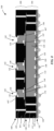
Referring now to FIG. 1 a cross-sectional side view illustration is provided of an optical package 100 including side-by-side controller chip 120 and optical components, including one or more emitters 140 and PD 130, in accordance with an embodiment. For example, the multiple different emitters 140 may be designed to emit at different wavelengths, or intensities. In an embodiment, an optical package 100 includes a back side routing layer 102 including a top side 103 and bottom side 104, and a printed circuit board (PCB) core 110 on the top side 103 of the back side routing layer 102. The PCB core 110 may include a plurality of vertical vias 112 and a plurality of cavities 115. A controller chip 120 is located face-up within a first cavity of the plurality of cavities 115, and a photodetector (PD) 130 is located within a second cavity of the plurality of cavities 115. A molding compound 150 encapsulates the controller chip 120 within the first cavity 115 and the PD 130 within the second cavity 115. The molding compound 150 may be formed of a suitable molding material, including epoxy, and more flexible materials such as silicone. A front side routing layer 160 is located on top of the controller chip 120, the molding compound 150, the PCB core 110. An aperture 162 is formed within the front side routing layer 160 over the PD 130. The optical package 100 may additionally include a plurality of solder bumps 170 on the bottom side 104 of the back side routing layer 102, for example, for mounting on a mother board or other system component of an electronic device.
The optical packages 100 in accordance with embodiments may include on or more emitters 140 and one or more PDs 130. In the particular embodiment illustrated in FIG. 1 , the one or more emitters 140 are located within respective cavities 115, and respective apertures 162 are formed within the front side routing layer 160 over the respective emitters 140, similarly as with the PD 130. As illustrated, the apertures 162 may have maximum widths that are less than the maximum widths of the top surfaces of the corresponding optical components (e.g. emitter, PD).
In accordance with embodiments, the PCB core 110 may be a laminate body 114. For example, the PCB core 110 can be a composite of woven fiberglass cloth and polymer (e.g. resin). The PCB core 110 may be formed of a variety of suitable PCB materials including FR4, prepreg, polyimide, etc. The PCB core 110 may be rigid or flexible. Vertical vias 112 may be copper pillars, for example, formed using a plating technique after drilling via holes through the PCB core 110. The PCB core 110 may include top side landing pads 116, and bottom side landing pads 118.
The optical components in accordance with embodiments may be vertical components, including top electrodes and bottom electrodes. Specifically, the PD 130 may have a top electrode 132 and bottom electrode 134, and the emitter(s) may have a top electrode 142 and bottom electrode 144. The front side routing layer 160 may include contact pads 165 that are formed on, and may be directly on, the top electrode 132 of the PD 130, and top electrode 142 of the emitters 140. Contact pads 165 may also be formed on, and may be directly on, the contact pads 122 of a face-up controller chip 120, and vertical vias 112 or top side landing pads 116.
In an embodiment such as that illustrated in FIG. 1 , the front side routing layer 160 can be a front redistribution layer (RDL), which may be formed directly on the underlying structure in a layer-by-layer process using thin film processing techniques. For example, a front RDL may include one or more metal traces 166, one or more dielectric layers 164, vias 168, and contact pads 165. The RDL may be formed of suitable materials. For example, the dielectric layer(s) 164 may be formed of a photoimageable dielectric material including polymers (e.g. polyimide, epoxy, epoxy blends, etc.) or inorganic materials (e.g. oxide, nitride), while the metal traces 166 and vias 168 may be formed of a suitable metal, including copper. Similarly contact pads 165 may be formed of on or more metals, including copper.
In an embodiment such as that illustrated in FIG. 1 , the back side routing layer 102 is an RDL. The back side routing layer 102 may be formed similarly as the front side routing layer 160 previously described. The back side routing layer 102 can include one or more dielectric layers 107, vias 108, contact pads 109, and optionally metal traces 106. In an embodiment, one or more of the dielectric layer(s) 107 is formed of the same material as the molding compound 150, and may be formed simultaneously with the molding compound 150. In accordance with embodiments, the PD 130 has a bottom electrode 134 that is electrically connected to the back side routing layer 102. Similarly, each emitter 140 has a bottom electrode 144 that is electrically connected to the back side routing layer 102. Vias 108 of the back side routing layer 102 may be formed through the dielectric layer 107 to make contact with the PD 130 and emitters 140. Dielectric layer 107 may be separate from, or a portion of the molding compound 150. In an embodiment, the vias 108 extend through the molding compound 150 to contact the bottom electrodes 134, 144 of the PD 130 and emitters 140, respectively, and may optionally extend through one or more additional dielectric layers 107. Vias 108 may additional contact a metal trace 106, or bottom side landing pad 118 of the PCB core 110.
FIG. 2 is a process flow of a method of fabricating the optical package of FIG. 1 in accordance with an embodiment. FIGS. 3A-3F are schematic cross-sectional side view illustrations of a method of fabricating the optical package of FIG. 1 in accordance with an embodiment. In interest of clarity and conciseness, the structures and process flow of FIGS. 2 and 3A-3F are described together in the following description.
At operation 2010 a PCB core 110 is placed on a carrier substrate 200. As shown in FIG. 3A, the carrier substrate 200 may include a support substrate 202 and adhesive layer 204. The controller chip 120 and optical components (e.g. PD 130, emitters 140) are then placed into the cavities 115 in the PCB core 110 at operation 2020, as illustrated in FIG. 3B. In an embodiment, the cavities 115 are deeper than the controller chip 120 and optical components are tall such that there is a clearance height.
Referring now to FIG. 3C, at operation 2030 the controller chip 120 and optical components are encapsulated in the PCB core 110, for example using a molding compound 150. In the particular embodiment illustrated in FIG. 3C, the molding compound 150 fills remaining volume within the cavities 115 not already occupied by the controller chip 120 and optical components, and may additionally cover the top surface (at this processing stage) of the PCB core 110 including what will be the bottom side landing pads 118. The carrier substrate 200 may then be removed at operation 2040 to expose top side landing pads 116, controller chip 120 contact pads 122, at top electrodes 142, 132 of the emitters 140 and PD 130.
The front side routing layer 160 is then formed at operation 2050. As illustrated in FIG. 3E, the front side routing layer 160 is an RDL including one or more metal traces 166, one or more dielectric layers 164, vias 168, and contact pads 165. Apertures 162 are additionally formed in the front side routing layer 160 to expose top surfaces of the optical components.
The back side routing layer 102 is then formed at operation 2060. As illustrated in FIG. 3F, the back side routing layer 102 is an RDL including one or more dielectric layers 107, vias 108, and contact pads 109, and optionally one or more metal traces 106. As shown in FIGS. 3D-3F, the back side routing layer 102 may include a portion of the molding compound 150. Thus, formation of the back side routing layer 102 may include forming vias 108 through the existing portion of the molding compound 150 covering the PCB core 110 from operation 2030. Additional dielectric layers 107 may also be formed. Dielectric layers 107 may be formed of suitable materials, including the molding compound 150 material, polymers, oxide, nitride, etc. Solder bumps 170 are then placed onto the contact pads 109.
FIGS. 4A-4B are schematic cross-section side view illustrations of optical packages 100 with optical components stacked on top of a controller chip 120 in accordance with embodiments. In each embodiment, the optical package 100 includes a first (lower) package level 180 and a second (upper) package level 480 on top of the first package level 180. Notably, the first package levels 180 in each of the embodiments illustrated in FIGS. 4A-4B may be similar to the optical package 100 of FIG. 1 , with the second package levels 480 of FIGS. 4A-4B being formed using alternative materials and processes.
In an embodiment, such as that illustrated in FIGS. 4A-4B, an optical package 100 includes a first package level 180 that includes a back side routing layer 102 including a top side 103 and a bottom side 104, and a controller chip 120 on the top side 103 of the back side routing layer 102. The first package level 180 additionally a front side routing layer 160 on top of the controller chip 120, and a first plurality of vertical vias 112 extending between the front side routing layer 160 and the back side routing layer 102. The first package level 180 may be substantially similar to the optical package 100 of FIG. 1 , less the optical components.
Still referring to FIGS. 4A-4B, the second package level 480 can include one or more PDs 130 mounted on an in electrical contact with the front side routing layer 160, and one or more emitters 140 mounted on and in electrical contact with the front side routing layer 160. A top side routing layer 460 is further located on an in electrical contact with the one or more PDs 130 and emitters 140, and a second plurality of vertical vias 412 extend between the top side routing layer 460 and the front side routing layer 160. Apertures 162 are formed within the top side routing layer 460 over the respective emitters 140, and PD 130 similarly as apertures 162 previously described.
In each of the embodiments illustrated in FIGS. 4A-4B, the controller chip 120 is face-up on the back side routing layer 102. Similar to FIG. 1 , in each of the embodiments illustrated in FIGS. 4A-4B the first package level 180 may include a PCB core 110 on the top side 103 of the back side routing layer 102, with the PCB core 110 including the first plurality of vertical vias 112 and a cavity 115, where the controller chip 120 is face-up within the cavity 115. The PCB core 410 may include top side landing pads 416, and bottom side landing pads 418.
The top side routing layer 460 can be a top redistribution layer (RDL), which may be formed on the underlying structure in a layer-by-layer process. For example, a top RDL may include one or more metal traces 466, one or more dielectric layers 464, vias 468, and contact pads 465. Contact pads 465 are formed on, and may be directly on, the top electrode 132 of the PD 130, and top electrode 142 of the emitters 140. The RDL may be formed of suitable materials. For example, the dielectric layer(s) 464 may be formed of a photoimageable dielectric material including polymers (e.g. polyimide, epoxy, epoxy blends, etc.) or inorganic materials (e.g. oxide, nitride), while the metal traces 466 and vias 468 may be formed of a suitable metal, including copper. Similarly contact pads 465 may be formed of one or more metals, including copper.
Referring to FIG. 4A, the second package level 480 may be formed similarly as the first package level 180. In an embodiment, the second package level 480 includes a second PCB core 410 on the front routing layer 160. Similar to PCB core 110, the second PCB core 410 includes a plurality of vertical vias 412 and a plurality of cavities 415, and each PD 130 and emitter 140 is within a respective cavity 415. The second package level 480 may be substantially fabricated separately from the first package level 180 then bonded together. In an embodiment, the second package level 480 is hybrid bonded to the first package level 180. This may occur at the panel level for example. Hybrid bonding may include a plurality of metal-metal bonds between the PCB core 410 and front side routing layer 160. For example, metal-metal bonds may be formed between bottom side landing pads 418 or vertical vias 412 of the PCB core 410, and/or bottom electrodes 144, 134 of the optical components, and the metal traces 166 (including contact pads 169) or vias 168 of the front side routing layer 160. Oxide-oxide bonds may be formed between dielectric layers 164 of the PCB core 410 and dielectric layer of the PCB core 410, which may be a surface layer or part of the body 414. Alternatively, the second package level 480 is hybrid bonded to the first package level 180 with a plurality of conductive joints, such as conductive past, conductive film, or solder bumps. In an embodiment solder bumps (not illustrated) are used to bond the bottom side landing pads 418 or vertical vias 412 of the PCB core 410 and metal traces 166 or vias 168 of the front side routing layer 160.
Referring to FIG. 4B, the second package level 480 may be formed on the first package level 180, for example using the first package level 180 as a reconstituted substrate. In such an embodiment, the PD 130, emitters 140, and the second plurality of vertical vias 412 can be encapsulated in a molding compound 490. The top side routing layer 460 may be formed similarly as the top side routing layer 460 of FIG. 4A.
FIG. 5A is a process flow of methods of fabricating the optical packages of FIGS. 4A-4B in accordance with embodiments. At operation 5010 the first package level 180 is formed including the controller chip 120 encapsulated in a PCB core 110. This process flow can be substantially similar to that illustrated and described with regard to FIGS. 1-3F, less the optical components. The fabrication sequence can then take different paths depending upon the structure of the second package level 480. In an embodiment, at operation 5020 a second package level 480 is bonded onto the first package level 180. For example, this may correspond to the embodiment illustrated in FIG. 4A in which the second package level 480 includes the optical components encapsulated within the PCB core 410. In an embodiment, at operation 5060 the second package level 480 is formed on the first package level 180. For example, this may correspond to the embodiment illustrated in FIG. 4B in which the second package level includes the optical components encapsulated within a molding compound 490. In further variations, this molding compound can be a laser direct structuring compatible molding compound.
Referring now to FIG. 5B, a process flow is provided of a method of fabricating the optical package of FIG. 4A in accordance with an embodiment. At operation 5022 a PCB core 410 is placed onto a carrier substrate. The optical components (e.g. one or more PDs 130 and one or more emitters 140) are placed within cavities 415 in the PCB core 410 at operation 5024. The optical components are then encapsulated in the PCB core 410 with a molding compound 450 at operation 5026. At this point, the top side routing layer 460 can optionally be formed at operation 5028, followed by removal of the carrier substrate at operation 5030. Bottom side landing pads 418, or additional routing, can then optionally be formed at operation 5032 on surface exposed after removal of the carrier substrate. The second package level 480 is then bonded to the first package level 180 at operation 5034. For example, this can be hybrid bonding or bonding with conductive bumps, such as solder bumping. In one variation, the top side routing layer 460 can be formed after bonding the second package level 480 to the first package level 180.
FIG. 5C is a process flow of a method of fabricating the optical package of FIG. 4B in accordance with an embodiment. At operation 5062 the optical components (e.g. one or more PDs 130 and one or more emitters 140) are placed onto the front side routing layer 160 of the first package level 180. For example, the optical components may be bonded using conductive bumps, such as conductive films, pastes, solder bumping, etc. As illustrated, bottom electrodes 144, 134 are bonded to the metal traces 166 (or contact pads 169) or vias 168 of the front side routing layer 160. The optical components are then encapsulated on the front side routing layer 160 with a molding compound 490 at operation 5064. The molding compound 490 may be opaque, e.g. black, in some embodiments. In some embodiments, vertical vias 412 are then formed at operation 5066 where the molding compound 490 is etched followed by plating of the vertical vias 412. Alternatively, the vertical vias 412 can be formed prior to encapsulation with the molding compound 490. For example, this can be by plating or gang bonding copper pins to the front side routing layer 160 with solder. The second package level top side routing layer 460 can then be formed on the molding compound 490 and the optical components as previously described at operation 5068.
As described in various embodiments, a molding compound can be used to encapsulate the optical components in the second package level. Further, while a PCB core 110 has been described and illustrated in at least the first package level, this is not required in accordance with embodiments, and the controller chip can alternatively be encapsulated with a molding compound similarly as with the optical components. In yet another variation, the molding compound used to encapsulate the optical components and/or controller chip can be a laser direct structuring (LDS) compatible material. In this manner, LDS structuring can be utilized to form a variety of interconnect structures through or on the molding compound, including vertical vias, and routing layers (inclusive of contact pads).
LDS compatible molding compounds in accordance with embodiments may include a matrix material, and a LDS additive dispersed in the matrix material. For example, the LDS additive may be a non-conductive metal organic compound. This may include a variety of metal oxide compositions, which may be compounded with (e.g. complexed) with the matrix material (e.g. resin). In an exemplary embodiment, the LDS additive is a dispersed tin oxide composition that is complexed with the matrix material. Embodiments are not limited to tin oxide, and a variety of other non-conductive metal organic compounds may be used, including other compounded metal oxides.
A variety of organic materials can be used for the matrix material, which may be dependent upon temperature exposure. Low temperatures materials include polycarbonate (PC) and acrilonitrile butadiene styrene (ABS). Medium temperature material that can withstand soldering temperatures include polycaprolactam (PA6/6) and polyphthalamides (PPA). A higher temperature material that can withstand virtually any soldering polyether ether ketone (PEEK). Other suitable material may include polypropylene (PP), polyethylene terpthalate (PET), polybutylene terpthalate (PBT), polyphenylene sulfide (PPS), and liquid crystal polymers (LCP).
The LDS additive, and laser parameters as selected so that upon application of the laser to the molding compound, the elemental metal in the non-conductive metal organic compound breaks from the compound and forms nucleation particles, forming a conducting path corresponding to the laser pattern. The nucleation particles can then be used as a nucleation layer for a subsequent electroless plating process to fully form the interconnect structures. Various metal layers can be formed with the electroless plating process including gold, nickel, silver, zinc, tin, etc.
FIG. 6A is a schematic cross-sectional side view illustration of an optical package 100 including optical components stacked on top of a controller chip 120 and second package level laser direct structuring in accordance with an embodiment. The embodiment illustrated in FIG. 6A is substantially similar to that illustrated and described with regard to FIG. 4B with a difference being the molding compound 491 being an LDS compatible material that includes a dispersed non-conductive metal organic compound. In such a configuration, LDS can be used to form trace routing 497 as well as the vertical vias 493. Alternatively trace routing 497 may be formed similarly as metal traces 466. In an embodiment, the top side routing layer 460 includes trace routing 497 that includes a nucleation layer of metal particles of the metal in the dispersed non-conductive metal organic compound. Similarly the vertical vias 493 can include the nucleation layer of metal particles of the metal in the dispersed non-conductive metal organic compound. Both the trace routing 497 and vertical vias 493 can additionally include a bulk conductive layer (e.g. copper) that is plated on top of the nucleation layer of metal particles. Trace routing 497 and vertical vias 493 may otherwise have similar layouts and connections as the metal traces 466 and vertical vias 412.
Referring briefly to FIG. 6B an exemplary vertical via 693 is illustrated as formed in an LDS compatible molding compound 600 including a top side 602 and bottom side 604. As shown, a laser pattern can be used to form metal nucleation layers 610 along sidewalls of the molding compound 600 that will become vertical vias 693. Additionally, the nucleation layers 612, 614 can be formed on the top and bottom sides of the molding compound to support additional electrical routing layers. In the illustrated embodiment, the vertical vias 693 are filled with a plated metal 620. Likewise, plated metal can be formed on the nucleation layers 612, 614 formed on the top and bottom sides of the molding compound in some embodiments to form trace routing or landing/contact pads. The exemplary vertical via 693 and nucleation layers illustrated in FIG. 6B are intended as an exemplary illustration for laser patterning of an LDS compatible molding compound 600, and can be implemented in the various embodiments described herein utilizing such a material.
In the particular embodiment illustrated in FIG. 6A, the first package level 180 includes a PCB core 110 on the top side of the back side routing layer 102, and a controller chip 120 face-up within a cavity 115 in the PCB core 110. The PD 130, emitters 140 and a second plurality of vertical vias 493 are encapsulated in a second level molding compound 491, which is an LDS compatible material including a dispersed non-conductive metal organic compound. The top side routing layer 460 includes a trace routing 497 which optionally includes a nucleation layer of metal particles of the metal in the dispersed non-conductive metal organic compound. The second plurality of vertical vias 493 may be similarly formed with the nucleation layer of metal particles.
FIG. 7 is a process flow of a method of fabricating the optical package of FIG. 6A in accordance with an embodiment. At operation 7010 the first package level 180 is formed including a controller chip 120 encapsulated in a PCB core 110, as previously described. At operation 7020 the optical components (PD and emitters) are placed on a front side routing layer 160 of the first package level 180. For example, front side routing layer 160 may be an RDL. The optical components are then encapsulated with an LDS compatible molding compound 491 at operation 7030. In an embodiment vertical vias 493 are then formed in the molding compound 491 at operation 7040. Formation of vertical vias 493 may include directing a laser at the molding compound 491 to form a nucleation layer of metal particles, following by an electroless plating operation for form a bulk metal layer of the vertical vias 493 on top of the nucleation layer. The top side routing layer (e.g. trace routing 497) is then formed on the molding compound 491 at operation 7050. For example, top side routing layer (e.g. trace routing 497) may also be formed by application of a laser pattern to the surface of the molding compound 491, followed by electroplating of a bulk metal layer pattern on the nucleation layer of metal particles. Alternatively, top side routing layer (e.g. trace routing 497) can be formed similarly as metal traces 466.
Referring now to FIG. 8 , a cross-sectional side view illustration of an optical package 100 is provided including optical components stacked on top of a controller chip, with first and second package level LDS in accordance with an embodiment. The embodiment illustrated in FIG. 8 differs from the embodiment illustrated in FIG. 6A in several respects. Notably, the first package level 180 is formed with an LDS compatible molding compound 411. Additionally, the processing sequence used results in a controller chip 120 that is face-down on the back side routing layer 102, which may optionally be a printed circuit board (PCB). In the embodiment illustrated, the controller chip 120 is encapsulated in an LDS compatible molding compound 411. The front side routing layer 160 may additionally include trace routing 467 that includes a nucleation layer of metal particles of the metal in a dispersed non-conductive metal organic compound in the LDS compatible molding compound 411. Likewise, vertical vias 413 may be similarly formed.
FIG. 9 is a process flow of a method of fabricating the optical package of FIG. 8 in accordance with an embodiment. FIGS. 10A-10F are schematic cross-sectional side view illustrations of a method of fabricating the optical package of FIG. 8 in accordance with an embodiment. In interest of clarity and conciseness, the structures and process flow of FIGS. 9 and 10A-10F are described together in the following description. At operation 9010 a controller chip 120 may be mounted on a back side routing layer 102, which may be PCB in an embodiment. As shown in FIG. 10A, the controller chip 120 can be mounted face-down, with contact pads 122 bonded to landing pads 105 or vias 107 of the back side routing layer 102, or PCB. In an embodiment, bonding facilitated by conductive film, conductive paste, or solder bumps. The controller chip is then encapsulated with an LDS compatible molding compound 411 at operation 9020.
Referring now to FIG. 10B, vertical vias 413 are formed within the molding compound at operation 9030, and front side routing layer 160 is formed on the molding compound at operation 9040. Vertical vias 413 may make contact with landing pads 105. Front side routing layer 160 may include a single layer of trace routing 467 formed using LDS, though additional dielectric and metal routing layers may optionally be included. Alternatively, the vertical vias 413 can be formed prior to encapsulation with the molding compound 411. For example, this can be by plating or gang bonding copper pins to the back side routing layer 102 with solder.
The optical components, including the PD 130 and emitters 140, are then placed onto the front side routing layer 160 at operation 9050, as illustrated in FIG. 10C. In an embodiment, this may be accomplished using conductive film, conductive paste, or solder bonding, so that bottom electrodes 144, 134 are bonded to and in electrical connection with the trace routing 467.
The optical components can then be encapsulated with a second LDS compatible molding compound 491 at operation 9060, as illustrated in FIG. 10D. Referring now to FIG. 10E, vertical vias 493 are formed within the molding compound 491 at operation 9070, and top side routing layer 460 is formed on the molding compound 491 at operation 9080. Vertical vias 493 may make contact with trace routing 467. Top side routing layer 460 may optionally include a single layer of trace routing 497 formed using LDS, though additional dielectric and metal routing layers may optionally be included or formed using alternative techniques. Additionally, apertures 162 are formed with the top side routing layer 460 to expose top surfaces of the optical components. As illustrated, the trace routing 497 may be formed on an in electrical contact with the top electrodes 132, 142 of the optical components. Solder bumps 170 may then be placed on contact pads 109 as illustrated in FIG. 10F for further system integration of the optical package 100.
FIG. 11 is a schematic cross-sectional side view illustration of another variation of an optical package 100 including optical components stacked on top of a controller chip 120, with first and second package level laser direct structuring in accordance with an embodiment. FIG. 11 is substantially similar to that of FIG. 8 , with one difference being that the method of manufacture may be substrate-less, and the back side routing layer 102 may instead by an RDL rather than PCB. FIG. 12 is a process flow of a method of fabricating the optical package of FIG. 11 in accordance with an embodiment. FIGS. 13A-13H are schematic cross-sectional side view illustrations of a method of fabricating the optical package of FIG. 11 in accordance with an embodiment. In interest of clarity and conciseness, the structure of FIG. 11 and process flows and structures of FIGS. 12 and 13A-13H are described together in the following description. At operation 1210 a controller chip 120 is placed on a carrier substrate 200. As illustrated in FIG. 13A, the controller chip may be placed face-down on the carrier substrate, followed by encapsulation with an LDS compatible molding compound 411 at operation 1220.
Referring now to FIG. 13B, vertical vias 413 are formed within the molding compound 411 at operation 1230, and front side routing layer 160 is formed on the molding compound 411 at operation 1240. Front side routing layer 160 may include a single layer of trace routing 467 formed using LDS, though additional dielectric and metal routing layers may optionally be included. The optical components, including the PD 130 and emitters 140, are then placed onto the front side routing layer 160 at operation 1250, as illustrated in FIG. 13C. In an embodiment, this may be accomplished using conductive film, conductive paste, or solder bonding, so that bottom electrodes 144, 134 are bonded to and in electrical connection with the trace routing 467.
The optical components can then be encapsulated with a second LDS compatible molding compound 491 at operation 1260, as illustrated in FIG. 13D. Referring now to FIGS. 13E-13F, the carrier substrate is removed at operation 1270, followed by the formation of a back side routing layer 102, which may be an RDL, at operation 1280. As shown, the back side routing layer 102 may include a dielectric layer 107, and a plurality of through vias 108, and contact pads 109. In an embodiment, dielectric layer 107 is a photoimageable polymer, and may be a molding compound material.
Referring now to FIG. 13G, vertical vias 493 are formed within the molding compound 491 at operation 1290, and top side routing layer 460 is formed on the molding compound 491 at operation 1292. Top side routing layer 460 may include a single layer of trace routing 497 formed using LDS, though additional dielectric and metal routing layers may optionally be included. Additionally, apertures 162 are formed with the top side routing layer 460 to expose top surfaces of the optical components. As illustrated, the trace routing 497 may be formed on an in electrical contact with the top electrodes 132, 142 of the optical components. Solder bumps 170 may then be placed on contact pads 109 as illustrated in FIG. 13H for further system integration of the optical package 100.
FIG. 14 is a schematic cross-sectional side view illustration of an optical package including optical components stacked on top of a controller chip, with first and second package level laser direct structuring in accordance with an embodiment. The optical package 100 of FIG. 14 may be similar to other optical packages including LDS with one difference being that the optical package 100 illustrated in FIG. 14 can be fabricated using a substrate-less packaging approach with the controller chip 120 integrated last. FIG. 15 is a process flow of a method of fabricating the optical package of FIG. 14 in accordance with an embodiment. FIGS. 16A-16H are schematic cross-sectional side view illustrations of a method of fabricating the optical package of FIG. 14 in accordance with an embodiment. In interest of clarity and conciseness, the structure of FIG. 14 and process flows and structures of FIGS. 15 and 16A-16H are described together in the following description.
At operation 1510 the optical components are placed on a carrier substrate 200. As illustrated in FIG. 16A, the optical components may be placed with top electrodes 142, 132 face-down on the carrier substrate, followed by encapsulation with an LDS compatible molding compound 491 at operation 1520. Referring now to FIG. 16B, vertical vias 413 are formed within the molding compound 491 at operation 1530, and front side routing layer 160 is formed on the molding compound 491 at operation 1540. As illustrated in FIG. 16C, front side routing layer 160 may be a RDL including one or more dielectric layers and metal routing layers as previously described, and may include a metal routing layer formed directly on the bottom electrodes 144, 134 of the optical components. The controller chip 120 is then placed face-down onto the front side routing layer 160 at operation 1550, as illustrated in FIG. 16D. In an embodiment, this may be accomplished using conductive film, conductive paste, or using solder bumps 270 as illustrated. The controller chip 120 can then be encapsulated with a second LDS compatible molding compound 411 at operation 1560, as illustrated in FIG. 16E. Referring now to FIG. 16F, vertical vias 413 are formed within the molding compound 411 at operation 1570, and back side routing layer 102 is formed on the molding compound 411. Back side routing layer 102 may include a single layer of trace routing formed using LDS, and can include contact pads 109, though additional dielectric and metal routing layers may optionally be included.
Referring now to FIGS. 16G-16H, the carrier substrate 200 is removed at operation 1580, followed by the formation of a top side routing layer 460, which may be an RDL, at operation 1590. As shown, apertures 162 are formed with the top side routing layer 460 to expose top surfaces of the optical components. As illustrated, the trace routing 497 may be formed on an in electrical contact with the top electrodes 132, 142 of the optical components. Solder bumps 170 may then be placed on contact pads 109 for further system integration of the optical package 100.
FIG. 17 is a schematic cross-sectional side view illustration of an optical package 100 including optical components stacked on top of a controller chip and wire bonding in accordance with an embodiment. FIG. 18 is a process flow of a method of fabricating the optical package of FIG. 17 in accordance with an embodiment. In the illustrated embodiment, the optical package can include a back side routing layer 102, which may be a PCB. The back side routing layer 102 includes including a top side 103 and bottom side 104. At operation 1810 a controller chip 120 is mounted face-down on the back side routing layer 102. For example, this may be accomplished with bonding with solder bumps 510 onto landing pads 105. One or more photodetectors 130 and emitters 140 are attached to the controller chip 120 at operation 1820, and wire bonded using wires 502 bonded to the back side routing layer 102 at operation 1830. As shown, the top electrodes 142, 132 are bonded to landing pads 105 using wires 502. Bottom electrodes 144, 134 can be bonded to trace lines 504 formed on top of the controller chip 120. The trace lines 504 in turn are wire bonded to the landing pads 105 with wires 502. At operation 1840 the wire bonded controller chip and optical components are enclosed. For example, this may be accomplished by mounting a metal lid onto the back side routing layer 102, or with a molding compound 500. FIG. 17 illustrates a molding compound 500 used to encapsulate the controller chip 120, the PD 130 and emitters 140 on the back side routing layer 102. Apertures 162 may additionally be formed over top surfaces of the optical components as previously described. In an embodiment, the molding compound 500 is opaque (e.g. a black mold). Alternatively, a metal lid may be used with similarly located apertures. An exemplary lid may have a shape corresponding to the outer contour of the illustrated molding compound 500, for example.
FIG. 19 is a schematic cross-sectional side view illustration of an optical package 100 including optical components stacked on top of a controller chip 120 and wire bonding in accordance with an embodiment. In particular, the embodiment of FIG. 19 combines certain aspects of the first package level 180 of previous embodiments with wire bonding of the optical components. In an embodiment, an optical package 100 includes a back side routing layer 102 including a top side 103 and bottom side 104, and a PCB core 110 on the top side of the back side routing layer 102. The PCB core 110 includes a plurality of vertical vias 112 and a cavity 115. The controller chip 120 is face-up within the cavity 115, and a molding compound 150 encapsulates the controller chip 120 within the cavity 115. A front side routing layer 160 is on top of the controller chip 120, the molding compound 150, and the PCB core 110. For example, the front side routing layer 160 can be an RDL as previously described. One or more PDs 130 and emitters 140 are mounted on a top side of the front side routing layer 160.
In an embodiment, the PD 130 includes a bottom electrode 134 directly over a first contact pad 169 of the front side routing layer 160, and a top electrode 132 wire bonded to a second contact pad 169 of the front side routing layer 160. The one or more emitter 140 top and bottom electrodes 142, 144 may be similarly connected. In the embodiment illustrated, the PD 130 (and corresponding wire 502) is encapsulated in a first transparent molding compound 600 and the emitter 140 (and corresponding wire 502) is encapsulated in a second transparent molding compound 600 that is separate from the first transparent molding compound.
The optical components may be enclosed using different techniques, such as a metal lid or molding compound. In the illustrated embodiment, an opaque molding compound encapsulates and surrounds the pre-molded PD 130 and emitter 140 (including the transparent molding compounds 600) on the front side routing layer 160. Apertures 162 may be formed as previously described. In an embodiment, a filter layer 601 such as a bandpass filter may be formed underneath the aperture 162 in order to select the wavelengths of light being transmitted through the aperture 162. Alternatively, a metal lid, with similar apertures, may be used in place of the molding compound 605.
Similar to previously described embodiments, a plurality of solder bumps 170 can be placed on the bottom side 104 of the back side routing layer 102 for additional integration. Additionally, the PCB core 110 can include a laminate body 114. The front side routing layer 160 may be an RDL, including one or more metal traces 166 and dielectric layers 164. The back side routing layer 102 may additionally be an RDL, and may optionally include a portion of the molding compound 150 and a plurality of through vias 108 extending through the molding compound 150. The optical package 100 of FIG. 19 may share additional features of other optical packages previously described.
FIG. 20 is a process flow of a method of fabricating the optical package of FIG. 19 in accordance with an embodiment. Operations 2010-2035 related to formation of the first package level 180 may be substantially similar to operations 2010-2060 described with regard to FIG. 2 , less the optical components. At operation 2010 a PCB core 110 is placed onto a carrier substrate 200. The controller chip 120 is placed into a cavity 115 within the PCB core 110 at operation 2015 and encapsulated at operation 2020. The carrier substrate 200 can then be removed at operation 2025, followed by the formation of the front side routing layer 160 at operation 2030 and back side routing layer 102 at operation 2035.
The optical components, including one or more PDs 130 and emitters 140, are then placed on the front side routing layer 160 at operation 2040 and wire bonded to the front side routing layer 160 at operation 2045. Each of the optical components is then encapsulated within a transparent molding compound 600 at operation 2050, followed by enclosing the molded optical components at operation 2055, for example by attaching a lid or molding with an opaque molding compound 605.
FIGS. 21A-23 illustrate various portable electronic devices in which the various embodiments can be implemented. FIGS. 21A-21B are schematic side view illustrations of an earbud in accordance with an embodiment that includes a housing 2102 and one or more openings 2110 to which the apertures 162 of the optical packages 100 described herein can be aligned. FIG. 22 is a schematic side view illustration of an earpiece in accordance with an embodiment that includes a housing 2202 including an opening 2210 to which the apertures 162 of the optical packages 100 described herein can be aligned. FIG. 23 is a schematic side view illustration of a mobile phone in accordance with an embodiment including a housing 2302 including an opening 2310 to which the apertures 162 of the optical packages 100 described herein can be aligned. These illustrations are intended to be exemplary and non-exhaustive implementations.
In utilizing the various aspects of the embodiments, it would become apparent to one skilled in the art that combinations or variations of the above embodiments are possible for forming an optical package. Although the embodiments have been described in language specific to structural features and/or methodological acts, it is to be understood that the appended claims are not necessarily limited to the specific features or acts described. The specific features and acts disclosed are instead to be understood as embodiments of the claims useful for illustration.

Claims (15)

What is claimed is:
1. An optical package comprising:
a back side routing layer including a top side and bottom side;
a printed circuit board (PCB) core on the top side of the back side routing layer, the PCB core including a plurality of vertical vias and a plurality of cavities;
a controller chip face-up within a first cavity of the plurality of cavities;
a photodetector (PD) within a second cavity of the plurality of cavities;
a molding compound encapsulating the controller chip within the first cavity and the PD within the second cavity;
a front side routing layer on top of the controller chip, the molding compound, and the PCB core; and
an aperture within the front side routing layer over the PD.
2. The optical package of claim 1, further comprising an emitter within a third cavity of the plurality of cavities, and a second aperture within the front side routing layer over the emitter.
3. The optical package of claim 2, further comprising a plurality of solder bumps on the bottom side of the back side routing layer.
4. The optical package of claim 2, wherein the PCB core comprises a laminate body.
5. The optical package of claim 2, wherein the front side routing layer includes a first contact pad on a top electrode of the PD, and the PD comprises a bottom electrode electrically connected to the back side routing layer.
6. The optical package of claim 5, further comprising a via extending through a portion of the molding compound to electrically connect the bottom electrode of the PD to the back side routing layer.
7. The optical package of claim 1, wherein the front side routing layer is a front redistribution layer (RDL) comprising one or more metal traces and one or more dielectric layers.
8. The optical package of claim 1, wherein the back side routing layer is a redistribution layer (RDL) comprising the molding compound and a plurality of through vias through the molding compound.
9. The optical package of claim 1, wherein the front side routing layer includes a first contact pad on a top electrode of the PD, and the PD comprises a bottom electrode electrically connected to the back side routing layer.
10. The optical package of claim 9, further comprising:
a first emitter within a third cavity of the plurality of cavities, and a second aperture within the front side routing layer over the first emitter; and
a second emitter within a fourth cavity of the plurality of cavities, and a third aperture within the front side routing layer over the second emitter.
11. The optical package of claim 10, wherein the first emitter is designed to emit at a different wavelength than the second emitter.
12. The optical package of claim 9, wherein the first contact pad of the front side routing layer is directly on the top electrode of the PD.
13. The optical package of claim 12, wherein the back side routing layer includes a via extending through the molding compound to contact the bottom electrode of the PD.
14. The optical package of claim 12, further comprising a plurality of solder bumps on the bottom side of the back side routing layer.
15. The optical package of claim 12, wherein the PCB core comprises a laminate body.
US16/911,153 2019-09-23 2020-06-24 Embedded packaging concepts for integration of ASICs and optical components Active 2041-01-26 US11651976B2 (en)

Priority Applications (1)

Application Number Priority Date Filing Date Title
US18/316,962 US20230386865A1 (en) 2019-09-23 2023-05-12 Embedded Packaging Concepts for Integration of ASICs and Optical Components

Applications Claiming Priority (2)

Application Number Priority Date Filing Date Title
SG10201908828W 2019-09-23
SG10201908828WA SG10201908828WA (en) 2019-09-23 2019-09-23 Embedded Packaging Concepts for Integration of ASICs and Optical Components

Related Child Applications (1)

Application Number Title Priority Date Filing Date
US18/316,962 Continuation US20230386865A1 (en) 2019-09-23 2023-05-12 Embedded Packaging Concepts for Integration of ASICs and Optical Components

Publications (2)

Publication Number Publication Date
US20210090908A1 US20210090908A1 (en) 2021-03-25
US11651976B2 true US11651976B2 (en) 2023-05-16

Family

ID=74881201

Family Applications (2)

Application Number Title Priority Date Filing Date
US16/911,153 Active 2041-01-26 US11651976B2 (en) 2019-09-23 2020-06-24 Embedded packaging concepts for integration of ASICs and optical components
US18/316,962 Pending US20230386865A1 (en) 2019-09-23 2023-05-12 Embedded Packaging Concepts for Integration of ASICs and Optical Components

Family Applications After (1)

Application Number Title Priority Date Filing Date
US18/316,962 Pending US20230386865A1 (en) 2019-09-23 2023-05-12 Embedded Packaging Concepts for Integration of ASICs and Optical Components

Country Status (4)

Country Link
US (2) US11651976B2 (en)
CN (1) CN112542451A (en)
SG (1) SG10201908828WA (en)
TW (1) TWI743909B (en)

Families Citing this family (5)

* Cited by examiner, † Cited by third party
Publication number Priority date Publication date Assignee Title
CN112103268B (en) * 2020-08-05 2021-08-03 珠海越亚半导体股份有限公司 Embedded packaging structure and manufacturing method thereof
US20220238473A1 (en) * 2021-01-25 2022-07-28 Stmicroelectronics S.R.L. Method of manufacturing semiconductor devices and corresponding semiconductor device
US20230213715A1 (en) * 2022-01-03 2023-07-06 Apple Inc. Technologies for Increased Volumetric and Functional Efficiencies of Optical Packages
CN117810215A (en) * 2022-09-22 2024-04-02 群创光电股份有限公司 Electronic device and spliced electronic device thereof
US20240105660A1 (en) * 2022-09-28 2024-03-28 Nxp Usa, Inc. Semiconductor device with active mold package and method therefor

Citations (21)

* Cited by examiner, † Cited by third party
Publication number Priority date Publication date Assignee Title
US20090115049A1 (en) 2007-11-06 2009-05-07 Shinko Electric Industries Co., Ltd. Semiconductor package
US20110064362A1 (en) 2009-09-11 2011-03-17 St-Ericsson Sa Integrated circuit device or package and integrated circuit system, with an optical wave-guide element
US20130221470A1 (en) 2012-02-29 2013-08-29 Larry D. Kinsman Multi-chip package for imaging systems
US20140097536A1 (en) 2012-10-09 2014-04-10 Avago Technologies General Ip (Singapore) Pte. Ltd TWO-SIDED-ACCESS EXTENDED WAFER-LEVEL BALL GRID ARRAY (eWLB) PACKAGE, ASSEMBLY AND METHOD
US20140296411A1 (en) 2013-04-01 2014-10-02 Sabic Innovative Plastics Ip B.V. High modulus laser direct structuring composites
US20150001713A1 (en) 2013-06-29 2015-01-01 Edmund Goetz Multiple level redistribution layer for multiple chip integration
US20150028359A1 (en) 2013-07-25 2015-01-29 Lingsen Precision Industries, Ltd. Package structure of an optical module
US20150262984A1 (en) * 2014-03-14 2015-09-17 Avago Technologies General Ip (Singapore) Pte. Ltd. METHODS FOR PERFORMING EMBEDDED WAFER-LEVEL PACKAGING (eWLP) AND eWLP DEVICES, PACKAGES AND ASSEMBLIES MADE BY THE METHODS
CN104961916A (en) 2015-07-11 2015-10-07 刘帅 Modified LDS (Laser Direct Structuring) additive and LCP (Liquid Crystal Polymer) composition containing same
KR20160116484A (en) 2015-03-30 2016-10-10 엘지이노텍 주식회사 Printed circuit board
US20170053903A1 (en) * 2015-08-17 2017-02-23 Rohm Co., Ltd. Optical semiconductor device
US9786617B2 (en) 2015-11-16 2017-10-10 Taiwan Semiconductor Manufacturing Company, Ltd. Chip packages and methods of manufacture thereof
US9905722B1 (en) 2016-12-27 2018-02-27 Advanced Semiconductor Engineering, Inc. Optical device, optical module structure and manufacturing process
US9911629B2 (en) 2016-02-10 2018-03-06 Taiwan Semiconductor Manufacturing Company, Ltd. Integrated passive device package and methods of forming same
US20180301443A1 (en) 2017-04-18 2018-10-18 Samsung Electronics Co., Ltd. Semiconductor package
US20190067244A1 (en) * 2017-08-28 2019-02-28 Taiwan Semiconductor Manufacturing Company Ltd. Semiconductor structure and manufacturing method thereof
US20190166684A1 (en) 2017-11-30 2019-05-30 Finisar Corporation High-speed hybrid circuit
US20190341505A1 (en) * 2018-05-03 2019-11-07 Advanced Semiconductor Engineering, Inc. Semiconductor device package and method of manufacturing the same
US20200006088A1 (en) * 2018-06-27 2020-01-02 Taiwan Semiconductor Manufacturing Company, Ltd. Photonic Integrated Package and Method Forming Same
US20210005761A1 (en) * 2019-07-03 2021-01-07 Advanced Semiconductor Engineering, Inc. Optical device and method of manufacturing the same
US20220131339A1 (en) * 2019-07-09 2022-04-28 Murata Manufacturing Co., Ltd. Optical device and method of manufacturing the same

Family Cites Families (2)

* Cited by examiner, † Cited by third party
Publication number Priority date Publication date Assignee Title
US8884431B2 (en) * 2011-09-09 2014-11-11 Taiwan Semiconductor Manufacturing Company, Ltd. Packaging methods and structures for semiconductor devices
EP3198644A4 (en) * 2014-09-26 2018-05-23 Intel Corporation Integrated circuit package having wire-bonded multi-die stack

Patent Citations (24)

* Cited by examiner, † Cited by third party
Publication number Priority date Publication date Assignee Title
US20090115049A1 (en) 2007-11-06 2009-05-07 Shinko Electric Industries Co., Ltd. Semiconductor package
US20110064362A1 (en) 2009-09-11 2011-03-17 St-Ericsson Sa Integrated circuit device or package and integrated circuit system, with an optical wave-guide element
US20130221470A1 (en) 2012-02-29 2013-08-29 Larry D. Kinsman Multi-chip package for imaging systems
US20140097536A1 (en) 2012-10-09 2014-04-10 Avago Technologies General Ip (Singapore) Pte. Ltd TWO-SIDED-ACCESS EXTENDED WAFER-LEVEL BALL GRID ARRAY (eWLB) PACKAGE, ASSEMBLY AND METHOD
US20140296411A1 (en) 2013-04-01 2014-10-02 Sabic Innovative Plastics Ip B.V. High modulus laser direct structuring composites
US20150001713A1 (en) 2013-06-29 2015-01-01 Edmund Goetz Multiple level redistribution layer for multiple chip integration
CN104681457A (en) 2013-06-29 2015-06-03 英特尔Ip公司 Multiple level redistribution layer for multiple chip integration
US20150028359A1 (en) 2013-07-25 2015-01-29 Lingsen Precision Industries, Ltd. Package structure of an optical module
US20150262984A1 (en) * 2014-03-14 2015-09-17 Avago Technologies General Ip (Singapore) Pte. Ltd. METHODS FOR PERFORMING EMBEDDED WAFER-LEVEL PACKAGING (eWLP) AND eWLP DEVICES, PACKAGES AND ASSEMBLIES MADE BY THE METHODS
KR20160116484A (en) 2015-03-30 2016-10-10 엘지이노텍 주식회사 Printed circuit board
CN104961916A (en) 2015-07-11 2015-10-07 刘帅 Modified LDS (Laser Direct Structuring) additive and LCP (Liquid Crystal Polymer) composition containing same
US20170053903A1 (en) * 2015-08-17 2017-02-23 Rohm Co., Ltd. Optical semiconductor device
US9786617B2 (en) 2015-11-16 2017-10-10 Taiwan Semiconductor Manufacturing Company, Ltd. Chip packages and methods of manufacture thereof
US9911629B2 (en) 2016-02-10 2018-03-06 Taiwan Semiconductor Manufacturing Company, Ltd. Integrated passive device package and methods of forming same
US9905722B1 (en) 2016-12-27 2018-02-27 Advanced Semiconductor Engineering, Inc. Optical device, optical module structure and manufacturing process
US20180182913A1 (en) 2016-12-27 2018-06-28 Advanced Semiconductor Engineering, Inc. Optical device, optical module structure and manufacturing process
TW201823799A (en) 2016-12-27 2018-07-01 日月光半導體製造股份有限公司 Optical device, optical module structure and manufacturing process
US20180301443A1 (en) 2017-04-18 2018-10-18 Samsung Electronics Co., Ltd. Semiconductor package
US20190067244A1 (en) * 2017-08-28 2019-02-28 Taiwan Semiconductor Manufacturing Company Ltd. Semiconductor structure and manufacturing method thereof
US20190166684A1 (en) 2017-11-30 2019-05-30 Finisar Corporation High-speed hybrid circuit
US20190341505A1 (en) * 2018-05-03 2019-11-07 Advanced Semiconductor Engineering, Inc. Semiconductor device package and method of manufacturing the same
US20200006088A1 (en) * 2018-06-27 2020-01-02 Taiwan Semiconductor Manufacturing Company, Ltd. Photonic Integrated Package and Method Forming Same
US20210005761A1 (en) * 2019-07-03 2021-01-07 Advanced Semiconductor Engineering, Inc. Optical device and method of manufacturing the same
US20220131339A1 (en) * 2019-07-09 2022-04-28 Murata Manufacturing Co., Ltd. Optical device and method of manufacturing the same

Non-Patent Citations (2)

* Cited by examiner, † Cited by third party
Title
Singapore Patent Application No. 10201908828W, "Search Report and Written Opinion" dated Aug. 3, 2020, 14 pages.
Taiwan Patent Application No. 109125516, "Search Report" dated Mar. 24, 2021, 1 pages.

Also Published As

Publication number Publication date
TW202114492A (en) 2021-04-01
TWI743909B (en) 2021-10-21
US20230386865A1 (en) 2023-11-30
CN112542451A (en) 2021-03-23
US20210090908A1 (en) 2021-03-25
SG10201908828WA (en) 2021-04-29

Similar Documents

Publication Publication Date Title
US11651976B2 (en) Embedded packaging concepts for integration of ASICs and optical components
US11508776B2 (en) Image sensor semiconductor packages and related methods
US9129980B2 (en) Package 3D interconnection and method of making same
US9173299B2 (en) Collective printed circuit board
US8623753B1 (en) Stackable protruding via package and method
US8642387B2 (en) Method of fabricating stacked packages using laser direct structuring
US7944043B1 (en) Semiconductor device having improved contact interface reliability and method therefor
US20170057808A1 (en) Mems chip package and method for manufacturing the same
US11817383B2 (en) Packaging technologies for temperature sensing in health care products
US20210358770A1 (en) Encapsulated semiconductor package
CN115398612A (en) System in an integrated package with radiation shielding
KR20140143567A (en) Semiconductor package board and method for maunfacturing the same
KR101944007B1 (en) Semiconductor package and method of manufacturing the same
US20110044017A1 (en) Electronic component
US11552053B2 (en) Miniaturization of optical sensor modules through wirebonded ball stacks
CN115867828A (en) Semiconductor package and method of manufacturing the same
US20230213715A1 (en) Technologies for Increased Volumetric and Functional Efficiencies of Optical Packages
TWM546011U (en) Electronic chip module with components on both sides
KR101168413B1 (en) Leadframe and method of manufacturig same
TWI669993B (en) Electronic chip module for double-sided mounting parts
KR101363108B1 (en) Printed circuit board with multi-layered structure
KR101672529B1 (en) One layer substrate and method for manufacturing the same, semiconductor package using the one layer substrate
KR20050073678A (en) Method for manufacturing bga type package
KR100646489B1 (en) Semiconductor Device and Method of fabricating the same
KR20150092632A (en) Embedded semiconductor die 3d package and its manufacturing methodology

Legal Events

Date Code Title Description
AS Assignment

Owner name: APPLE INC., CALIFORNIA

Free format text: ASSIGNMENT OF ASSIGNORS INTEREST;ASSIGNORS:RENJAN, KISHORE N.;KANI, BILAL MOHAMED IBRAHIM;KIM, KYUSANG;AND OTHERS;SIGNING DATES FROM 20191011 TO 20191015;REEL/FRAME:053031/0157

FEPP Fee payment procedure

Free format text: ENTITY STATUS SET TO UNDISCOUNTED (ORIGINAL EVENT CODE: BIG.); ENTITY STATUS OF PATENT OWNER: LARGE ENTITY

STPP Information on status: patent application and granting procedure in general

Free format text: DOCKETED NEW CASE - READY FOR EXAMINATION

STPP Information on status: patent application and granting procedure in general

Free format text: NON FINAL ACTION MAILED

STPP Information on status: patent application and granting procedure in general

Free format text: RESPONSE TO NON-FINAL OFFICE ACTION ENTERED AND FORWARDED TO EXAMINER

STPP Information on status: patent application and granting procedure in general

Free format text: NON FINAL ACTION MAILED

STPP Information on status: patent application and granting procedure in general

Free format text: RESPONSE TO NON-FINAL OFFICE ACTION ENTERED AND FORWARDED TO EXAMINER

STCF Information on status: patent grant

Free format text: PATENTED CASE