US11649048B2 - Wall scaling unmanned aircraft and method of controlling - Google Patents
Wall scaling unmanned aircraft and method of controlling Download PDFInfo
- Publication number
- US11649048B2 US11649048B2 US16/376,742 US201916376742A US11649048B2 US 11649048 B2 US11649048 B2 US 11649048B2 US 201916376742 A US201916376742 A US 201916376742A US 11649048 B2 US11649048 B2 US 11649048B2
- Authority
- US
- United States
- Prior art keywords
- aircraft body
- aircraft
- pair
- wall surface
- vertical wall
- Prior art date
- Legal status (The legal status is an assumption and is not a legal conclusion. Google has not performed a legal analysis and makes no representation as to the accuracy of the status listed.)
- Active, expires
Links
- 238000000034 method Methods 0.000 title claims description 16
- 230000002093 peripheral effect Effects 0.000 claims description 4
- 238000001514 detection method Methods 0.000 claims 2
- 238000005516 engineering process Methods 0.000 description 4
- 238000012545 processing Methods 0.000 description 4
- 238000012986 modification Methods 0.000 description 3
- 230000004048 modification Effects 0.000 description 3
- 230000008901 benefit Effects 0.000 description 2
- 230000004075 alteration Effects 0.000 description 1
- 230000000694 effects Effects 0.000 description 1
- 238000007689 inspection Methods 0.000 description 1
- 230000008520 organization Effects 0.000 description 1
- 238000010422 painting Methods 0.000 description 1
- 230000004044 response Effects 0.000 description 1
- 230000008054 signal transmission Effects 0.000 description 1
- 238000006467 substitution reaction Methods 0.000 description 1
Images


Classifications
-
- B—PERFORMING OPERATIONS; TRANSPORTING
- B64—AIRCRAFT; AVIATION; COSMONAUTICS
- B64C—AEROPLANES; HELICOPTERS
- B64C39/00—Aircraft not otherwise provided for
- B64C39/02—Aircraft not otherwise provided for characterised by special use
- B64C39/024—Aircraft not otherwise provided for characterised by special use of the remote controlled vehicle type, i.e. RPV
-
- B—PERFORMING OPERATIONS; TRANSPORTING
- B64—AIRCRAFT; AVIATION; COSMONAUTICS
- B64C—AEROPLANES; HELICOPTERS
- B64C25/00—Alighting gear
- B64C25/32—Alighting gear characterised by elements which contact the ground or similar surface
- B64C25/34—Alighting gear characterised by elements which contact the ground or similar surface wheeled type, e.g. multi-wheeled bogies
- B64C25/36—Arrangements or adaptations of wheels, tyres or axles in general
-
- B—PERFORMING OPERATIONS; TRANSPORTING
- B64—AIRCRAFT; AVIATION; COSMONAUTICS
- B64D—EQUIPMENT FOR FITTING IN OR TO AIRCRAFT; FLIGHT SUITS; PARACHUTES; ARRANGEMENT OR MOUNTING OF POWER PLANTS OR PROPULSION TRANSMISSIONS IN AIRCRAFT
- B64D35/00—Transmitting power from power plants to propellers or rotors; Arrangements of transmissions
- B64D35/02—Transmitting power from power plants to propellers or rotors; Arrangements of transmissions specially adapted for specific power plants
-
- B—PERFORMING OPERATIONS; TRANSPORTING
- B64—AIRCRAFT; AVIATION; COSMONAUTICS
- B64D—EQUIPMENT FOR FITTING IN OR TO AIRCRAFT; FLIGHT SUITS; PARACHUTES; ARRANGEMENT OR MOUNTING OF POWER PLANTS OR PROPULSION TRANSMISSIONS IN AIRCRAFT
- B64D47/00—Equipment not otherwise provided for
- B64D47/08—Arrangements of cameras
-
- B—PERFORMING OPERATIONS; TRANSPORTING
- B64—AIRCRAFT; AVIATION; COSMONAUTICS
- B64U—UNMANNED AERIAL VEHICLES [UAV]; EQUIPMENT THEREFOR
- B64U2101/00—UAVs specially adapted for particular uses or applications
-
- B—PERFORMING OPERATIONS; TRANSPORTING
- B64—AIRCRAFT; AVIATION; COSMONAUTICS
- B64U—UNMANNED AERIAL VEHICLES [UAV]; EQUIPMENT THEREFOR
- B64U2101/00—UAVs specially adapted for particular uses or applications
- B64U2101/30—UAVs specially adapted for particular uses or applications for imaging, photography or videography
-
- B—PERFORMING OPERATIONS; TRANSPORTING
- B64—AIRCRAFT; AVIATION; COSMONAUTICS
- B64U—UNMANNED AERIAL VEHICLES [UAV]; EQUIPMENT THEREFOR
- B64U2101/00—UAVs specially adapted for particular uses or applications
- B64U2101/60—UAVs specially adapted for particular uses or applications for transporting passengers; for transporting goods other than weapons
-
- B—PERFORMING OPERATIONS; TRANSPORTING
- B64—AIRCRAFT; AVIATION; COSMONAUTICS
- B64U—UNMANNED AERIAL VEHICLES [UAV]; EQUIPMENT THEREFOR
- B64U2201/00—UAVs characterised by their flight controls
- B64U2201/20—Remote controls
-
- B—PERFORMING OPERATIONS; TRANSPORTING
- B64—AIRCRAFT; AVIATION; COSMONAUTICS
- B64U—UNMANNED AERIAL VEHICLES [UAV]; EQUIPMENT THEREFOR
- B64U30/00—Means for producing lift; Empennages; Arrangements thereof
- B64U30/20—Rotors; Rotor supports
-
- B—PERFORMING OPERATIONS; TRANSPORTING
- B64—AIRCRAFT; AVIATION; COSMONAUTICS
- B64U—UNMANNED AERIAL VEHICLES [UAV]; EQUIPMENT THEREFOR
- B64U50/00—Propulsion; Power supply
- B64U50/10—Propulsion
- B64U50/19—Propulsion using electrically powered motors
-
- Y—GENERAL TAGGING OF NEW TECHNOLOGICAL DEVELOPMENTS; GENERAL TAGGING OF CROSS-SECTIONAL TECHNOLOGIES SPANNING OVER SEVERAL SECTIONS OF THE IPC; TECHNICAL SUBJECTS COVERED BY FORMER USPC CROSS-REFERENCE ART COLLECTIONS [XRACs] AND DIGESTS
- Y02—TECHNOLOGIES OR APPLICATIONS FOR MITIGATION OR ADAPTATION AGAINST CLIMATE CHANGE
- Y02T—CLIMATE CHANGE MITIGATION TECHNOLOGIES RELATED TO TRANSPORTATION
- Y02T50/00—Aeronautics or air transport
- Y02T50/80—Energy efficient operational measures, e.g. ground operations or mission management
Definitions
- the embodiments disclosed herein are related to an aircraft and a method of controlling the aircraft.
- an aircraft includes: an aircraft body including a plurality of rotating wings and a plurality of motors that rotates the plurality of rotating wings; a pair of wheels arranged on both sides of the aircraft body and rotatably supported by the aircraft body around an axis that extends in a left and right direction of the aircraft body; a pair of rollers that protrude forward and upward with respect to each of the wheels when the aircraft body is in a horizontal state, and are rotatably supported by the aircraft body around an axis that extends in a tangential direction of each of the wheels; and a controller that controls a rotation speed of the plurality of motors such that, when the aircraft body is moved in the left and right direction along a vertical wall surface, the aircraft body is inclined forward to bring the pair of rollers into contact with the vertical wall surface, and the aircraft body is inclined to a side where the aircraft body moves in the left and right direction.
- FIG. 1 is a perspective view of an aircraft according to an embodiment
- FIG. 2 is a front view of the aircraft of FIG. 1 ;
- FIG. 3 is a left side view of the aircraft of FIG. 1 ;
- FIG. 4 is a top view of the aircraft of FIG. 1 ;
- FIG. 5 is a block view illustrating a configuration of the aircraft of FIG. 1 ;
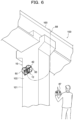
- FIG. 6 is a view illustrating an example of a method for using the aircraft of FIG. 1 ;
- FIG. 7 is a view illustrating a flow of processing in mode switching in a controller applied to the aircraft of FIG. 1 ;
- FIG. 8 is a view illustrating a flow of processing in a left and right contact movement mode in the controller applied to the aircraft of FIG. 1 ;
- FIG. 9 is a left side view illustrating a state where an aircraft body is inclined forward to an extent that a pair of rollers are not brought into contact with a vertical wall surface in a method of controlling the aircraft of FIG. 1 ;
- FIG. 10 is a left side view illustrating a state where the aircraft body is inclined forward to an extent that the pair of rollers are brought into contact with the vertical wall surface in the method of controlling the aircraft of FIG. 1 ;
- FIG. 11 is a front view illustrating a state where the aircraft body is inclined to the right side in the method of controlling the aircraft of FIG. 1 ;
- FIG. 12 is a front view illustrating a state where the aircraft body is inclined to the left side in the method of controlling the aircraft of FIG. 1 .
- an aircraft may be proposed that includes a pair of wheels provided on both of the left and right sides of the plurality of rotating wings, and moves on a vertical wall surface by causing the pair of wheels to be brought into contact with the vertical wall surface.
- a pair of wheels are rotatably supported around an axis that extends in a left and right direction in the aircraft. Therefore, it is difficult to move the aircraft in the left and right direction in a state where the pair of wheels are brought into contact with a vertical wall surface.
- the technology disclosed herein has been made in consideration of the circumstances. As, one aspect, the technology disclosed herein is to provide an aircraft capable of moving in the left and right direction while being brought into contact with a vertical wall surface.
- an aircraft As illustrated in FIGS. 1 to 4 , an aircraft according to the embodiment includes an aircraft body 12 and a pair of wheels 50 .
- the arrows FR, UP, and RH illustrated in the each drawing indicate a front side in the front and rear direction of the aircraft 10 , an upper side in the vertical direction of the aircraft 10 , and a right side in the left and right direction of the aircraft 10 , respectively.
- the aircraft body 12 includes a frame 20 , a plurality of rotating wings 40 A to 40 D, a plurality of motors 41 A to 41 D, and a pair of rollers 42 .
- the frame 20 forms a skeleton of the aircraft body 12 and includes an inner frame 21 and an outer frame 31 .
- the inner frame 21 is an example of a “first frame portion,” and has a frame shape when viewed from the top.
- the inner frame 21 includes a pair of front and rear connecting members 22 that extend in the front and rear direction of the aircraft 10 , and a pair of left and right connecting members 23 that extend in the left and right direction of the aircraft 10 .
- Both left and right ends of the pair of left and right connecting members 23 are coupled to the pair of front and rear connecting members 22 .
- the pair of left and right connecting members 23 intersect with the pair of front and rear connecting members 22 at connecting portions with the pair of front and rear connecting members 22 .
- the connecting portions between the pair of left and right connecting members 23 and the pair of front and rear connecting members 22 correspond to intersecting portions 24 A to 24 D.
- a total of four intersecting portions 24 A to 24 D are formed on the inner frame 21 .
- the plurality of intersecting portions 24 A to 24 D are arranged at the front, the rear, the left, and the right of the aircraft 10 .
- the outer frame 31 includes a plurality of connecting rods 32 A to 32 F that extend in the left and right direction of the aircraft 10 , a pair of annular members 33 arranged on both left and right sides of the plurality of connecting rods 32 A to 32 F, and a plurality of spokes 34 A to 34 F provided inside of the pair of annular members 33 .
- the pair of annular members 33 form an annular shape around an axis L 1 that extends in the left and right direction of the aircraft body 12 , and the plurality of spokes 34 A to 34 F are radially formed around a center portion of the annular member 33 .
- Distal ends of the plurality of spokes 34 A to 34 F are coupled to the annular member 33 .
- distal ends of the plurality of spokes 34 A to 34 F on the left side and distal ends of the plurality of spokes 34 A to 34 F on the right side are coupled by the plurality of connecting rods 32 A to 32 F, respectively.
- the outer frame 31 includes an outer frame portion 35 having a rectangular frame shape that surrounds the inner frame 21 when viewed from the top.
- the outer frame portion 35 includes a plurality of spokes 34 A and 34 B that extends in the front and rear direction of the aircraft 10 among the plurality of spokes 34 A to 34 F on both of the left and right sides, and a front side connecting rod 32 A and a rear side connecting rod 32 B that are coupled to the plurality of spokes 34 A and 34 B.
- the outer frame portion 35 is an example of a “second frame portion.” Front ends of the pair of front and rear connecting members 22 are coupled to the front side connecting rod 32 A, and rear ends of the pair of front and rear connecting members 22 are coupled to the rear side connecting rod 32 B.
- the outer frame 31 is provided with a support rod 36 that extends in the left and right direction of the aircraft 10 and a rotating member 37 that is rotatably supported by the support rod 36 .
- the support rod 36 is arranged above the center portion (a center portion of the plurality of spokes 34 A to 34 F) of the pair of annular members 33 .
- the support rod 36 is arranged between a pair of spokes 34 C and 34 D at an upper side among the plurality of spokes 34 A to 34 F, and is fixed to the pair of spokes 34 C and 34 D at the upper side. Both ends of the support rod 36 penetrate the pair of annular members 33 , and protrude to both of the left and right sides of the aircraft 10 more than the pair of annular members 33 .
- the rotating member 37 is formed in a rectangular arch shape having a pair of lateral rods 38 and a central rod 39 that connects the distal ends of the pair of lateral rods 38 .
- the pair of lateral rods 38 are arranged on both of the left and right sides of the aircraft 10 beyond the pair of annular members 33 , and extend in the diametric direction of the pair of annular members 33 .
- the base ends of the pair of lateral rods 38 are turnably coupled to the both ends of the support rods 36 , respectively.
- the pair of lateral rods 38 are formed to have a length such that the central rod 39 is able to circulate around the outside in the diametric direction of the pair of annular members 33 .
- the central rod 39 is connected with for example, a cable for power supply and signal transmission/receiving, or a wire for preventing the aircraft 10 from dropping or limiting the moving range of the aircraft 10 .
- the plurality of rotating wings 40 A to 40 D are arranged at the four intersecting portions 24 A to 24 D described above for each in two rows vertically.
- the rotating wings 40 A at the right front side are arranged vertically at the intersecting portion 24 A at right front side
- the rotating wings 40 B at the left front side are arranged vertically at the intersecting portion 24 B at the left front side.
- the rotating wings 40 C at the right rear side are arranged vertically at the intersecting portion 24 C at the right rear side
- the rotating wings 40 D at the left rear side are arranged vertically at the intersecting portion 24 D at the left rear side.
- the plurality of rotating wings 40 A to 40 D are arranged at the four intersecting portions 24 A to 24 D in two rows vertically, so that the rotating wings 40 A at the right front side, the rotating wings 40 B at the left front side, the rotating wings 40 C at the right rear side, and the rotating wings 40 D at the left rear side are arranged at the front and rear, and the left and right of the aircraft 10 . All of the plurality of rotating wings 40 A to 40 D are arranged with the vertical direction of the aircraft 10 as the axial direction.
- the rotating wings 40 A at the light front side and the rotating wings 40 B at the left front side may be referred to as “front side rotating wings 40 A and 40 B,” and the rotating wings 40 C at the right rear side and the rotating wings 40 D at the left rear side may be referred to as “rear side rotating wings 40 C and 40 D.”
- the rotating wings 40 A at the right front side and the rotating wings 40 C at the right rear side may be referred to as “right side rotating wings 40 A and 40 C,” and the rotating wings 40 B at the left front side and the rotating wings 40 D at the left rear side may be referred to as “left side rotating wings 40 B and 40 D.”
- the front side rotating wings 40 A and 40 B and the rear side rotating wings 40 C and 40 D are arranged symmetrically in the front and rear direction, and the right side rotating wings 40 A and 40 C and the left side rotating wings 40 B and 40 D are arranged symmetrically in the left and right direction.
- the plurality of motors 41 A to 41 D are fixed at the four intersecting portions 24 A to 24 D described above for each in two rows vertically. All of the plurality of motors 41 A to 41 D are arranged with the vertical direction of the aircraft 10 as the axial direction.
- the plurality of rotating wings 40 A to 40 D described above are fixed to output shafts of the plurality of motors 41 A to 41 D, respectively.
- the plurality of motors 41 A to 41 D rotate the plurality of rotating wings 40 A to 40 D, respectively.
- the plurality of motors 41 A to 41 D are able to independently adjust the rotation speed of the plurality of rotating wings 40 A to 40 D.
- the rotating wings 40 A at the right front side and the left rear side rotating wings 40 D at the left rear side rotate in a same direction
- the rotating wings 40 B at the left front side and the rotating wings 40 C at the right rear side rotate in a direction opposite to the rotating direction of the rotating wings 40 A at the right front side and the rotating wings 40 D at the left rear side.
- the rotating wings that are adjacent to each other in the front and rear direction or the left and right direction of the aircraft among the plurality of rotating wings 40 A to 40 D rotate in different directions.
- the pair of wheels 50 are rotatably supported by the annular members 33 over the entire circumference, respectively.
- the pair of wheels 50 are supported by the annular members 33 , so that the wheels 50 are arranged on both of the left and right sides of the aircraft body 12 , and are rotatable around the axis L 1 that extends in the left and right direction of the aircraft body 12 .
- the pair of wheels 50 are arranged on both of the left and right sides of the plurality of rotating wings 40 A to 40 D. Further, the front ends of the pair of wheels 50 are positioned at the front of the plurality of rotating wings 40 A to 40 F when viewed from a side surface of the aircraft 10 .
- Support members 43 configured to rotatably support the pair of rollers 42 are provided at the pair of annular members 33 that rotatably support the wheels 50 , respectively.
- Each of the support members 43 has a rotation shaft that extends in a tangential direction of each of the wheels 50 .
- the tangential direction of the wheel 50 that is an axial direction of the rotation shaft 44 is in a twisted position with respect to the axial direction of the wheel 50 .
- the tangential direction of the wheel 50 does not necessarily coincide with a tangent of an outer peripheral surface of the wheel 50 , and may be parallel with the tangent of the outer peripheral surface of each of the wheels 50 .
- the pair of rollers 42 are rotatably supported by each of the rotation shafts 44 .
- the pair of rollers 42 are supported by each of the rotation shafts 44 so as to be rotatable around the axis L 2 that extends in the tangential direction of each of the wheels 50 .
- the pair of rollers 42 are arranged at positions where the rollers 42 protrude forward and upward with respect to each of the wheels 50 when the aircraft body 12 is in a horizontal state.
- the roller 42 is formed in an elliptical spherical shape whose major axial direction is the axial direction of the rotation shaft 44 .
- a contact surface 42 A (outer peripheral surface) of the roller 42 with the vertical wall surface forms a convex curved surface shape when viewed from the side surface of the aircraft body 12 (aircraft 10 ).
- the pair of rollers 42 and the pair of wheels 50 are supported by the annular members 33 provided at the aircraft body 12 . Therefore, as described later, when the aircraft body 12 is inclined to a side where the aircraft body 12 moves in the left and right direction, the pair of rollers 42 and the pair of wheels 50 are inclined together with the aircraft body 12 in order to move the aircraft 10 in the left and right direction. In this manner, in the embodiment, since the pair of rollers 42 and the pair of wheels 50 are inclined together with the aircraft body 12 , the inclination of the aircraft body 12 to the side where the aircraft body 12 moves in the left and right direction is synonymous with the inclination of the aircraft 10 to the side where the aircraft 10 moves in the left and right direction.
- the aircraft 10 includes an upper sensor 82 , a front sensor 83 , a plurality of cameras 84 , a battery 85 , and a controller 86 .
- the upper sensor 82 is for detecting an object positioned above the aircraft 10
- the front sensor 83 is for detecting an object positioned in front of the aircraft 10
- the upper sensor 82 is arranged facing upward of the aircraft 10
- the front sensor 83 is arranged facing the front of the aircraft 10 .
- Various types of sensors may be applied to the upper sensor 82 and the front sensor 83 .
- the plurality of cameras 84 are for photographing the front of the aircraft 10 , and are arranged to face the front of the aircraft 10 at both of the left and right sides of the aircraft 10 .
- the plurality of cameras 84 are respectively fixed to the center portion and both ends of the support rod 36 (see, e.g., FIG. 1 ).
- the controller 86 an operating unit 87 , and the battery 85 are only illustrated in FIG. 5 .
- the controller 86 is realized by, for example, an electronic circuit (computer) including, for example, a calculation unit and a storage unit.
- the controller 86 is electrically coupled to the upper sensor 82 , the front sensor 83 , the plurality of cameras 84 , and the plurality of motors 41 A to 41 D (flying motors). Further, the controller 86 is coupled to the operating unit 87 so as to receive an operation signal. The operation of the controller 86 will be described later.
- the battery 85 is configured to supply power to the upper sensor 82 , the front sensor 83 , the plurality of cameras 84 , the plurality of motors 41 A to 41 D, and the controller 86 described above.
- the controller 86 and the battery 85 may be mounted on the frame 20 , and also, may be mounted on an operating device provided near an operator. When the controller and the battery 85 are mounted on the operating device provided near the operator, the controller 86 and the battery 85 are electrically connected to a relay board mounted on the frame 20 via, for example, a cable or the like.
- FIG. 6 An example of the method for using the aircraft 10 of FIG. 1 is illustrated in FIG. 6 .
- FIGS. 1 to 5 An example of the method for using the aircraft 10 of FIG. 1 is illustrated in FIG. 6 .
- FIGS. 1 to 5 An example of the method for using the aircraft 10 of FIG. 1 is illustrated in FIG. 6 .
- the aircraft 10 flies toward a vertical wall surface 102 of a bridge pier 101 provided at a bridge 100 and the pair of wheels 50 are brought into contact with the vertical wall surface 102 and the aircraft 10 moves on the vertical wall surface 102 .
- the controller 86 and the battery 85 are disposed on a bridge girder 103 , and the controller 86 and the battery 85 are coupled with the aircraft body 12 via a cable 88 .
- the aircraft 10 flies according to the operation of the operating unit 87 by the operator. When the aircraft 10 moves on the vertical wall surface 102 , for example, the vertical wall surface 102 is photographed by the plurality of cameras 84 .
- the controller 86 detects that the pair of wheels 50 are brought into contact with the vertical wall surface 102 based on, for example, the detecting results of a contact sensor or the front sensor provided at the aircraft body 12 . Then, the controller 86 performs processings of steps S 1 to S 5 illustrated in FIG. 7 when it is detected that the pair of wheels 50 are brought into contact with the vertical wall surface 102 .
- step S 1 the controller 86 confirms a movement command from the operating unit 87 . Then, the controller 86 determines whether the movement command from the operating unit 87 is a vertical direction movement command in step S 2 . Here, when it is determined that the movement command from the operating unit 87 is the vertical direction movement command, the controller 86 proceeds with step S 3 .
- step S 3 the controller 86 enters a “vertical contact movement mode.” Then, as illustrated in FIG. 9 , the controller 86 controls the rotation speed of the plurality of motors 41 A to 41 D so that the aircraft body 12 is in a forward inclined posture such that the pair of rollers 42 are not brought into contact with the vertical wall surface 102 . At this time, the controller 86 controls the rotation speed of the plurality of motors 41 A to 41 D such that the rotation speed of the rear side motors 41 C and 41 D among the plurality of motors 41 A to 41 D is higher than that of the front side motors 41 A and 41 B. In this manner, when the aircraft body 12 is in the forward inclined posture such that the pair of rollers 42 are not brought into contact with the vertical wall surface 102 , pressing force to the vertical wall surface 102 acts on the pair of wheels 50 .
- the controller 86 controls the rotation speed of the plurality of motors 41 A to 41 D such that the aircraft body 12 is moved in the vertical direction based on the vertical direction movement command from the operating unit 87 while the aircraft body 12 maintains the forward inclined posture. In this manner, when the aircraft body 12 moves in the vertical direction, the pair of wheels 50 run on the vertical wall surface 102 , and thus, the vertical direction movement of the aircraft body 12 is stabilized.
- step S 4 determines whether the movement command from the operating unit 87 is a left and right direction movement command in step S 4 .
- the controller 86 returns to step S 1 .
- the controller 86 proceeds with step S 5 .
- the controller 86 enters a “left and right contact movement mode,” and performs processings of steps S 11 to S 19 illustrated in FIG. 8 .
- step S 11 the controller 86 controls the rotation speed of the plurality of motors 41 A to 41 D so as to bring the pair of rollers 42 into contact with the vertical wall surface 102 , thereby causing the aircraft body 12 to be inclined forward.
- step S 12 the controller 86 determines whether the aircraft body 12 is inclined forward until the pair of rollers 42 are brought into contact with the vertical wall surface 102 .
- the controller 86 determines whether the aircraft body 12 is inclined forward until the pair of rollers 42 are brought into contact with the vertical wall surface 102 based on, for example, the detecting results of a sensor that detects that the pair of rollers 42 are brought into contact with the vertical wall surface 102 , a sensor that detects the forward inclination angle of the aircraft body 12 or the like. Then, as illustrated in FIG.
- the controller 86 determines that the aircraft body 12 is inclined forward until the pair of rollers 42 are brought into contact with the vertical wall surface 102 , and the controller 86 proceeds with step S 13 . More specifically, the controller 86 causes the aircraft body 12 to be inclined forward until the pair of rollers 42 that protrude with respect to each of the wheels 50 are brought into contact with the vertical wall surface 102 and each of the wheels 50 is separated from the vertical wall surface 102 .
- step S 13 the controller 86 confirms a left and right movement command from the operating unit 87 .
- step S 14 the controller 86 determines whether the left and right movement command from the operating unit 87 is a right side movement command.
- the controller 86 proceeds with step S 15 .
- step S 15 the controller 86 controls the rotation speed of the plurality of motors 41 A to 41 D to cause the aircraft body 12 to be inclined to the right side where the aircraft body 12 moves in the left and right direction, as illustrated in FIG. 11 .
- the controller 86 controls the rotation speed of the plurality of motors 41 A to 41 D such that the rotation speed of the left side motors 41 B and 41 D among the plurality of motors 41 A to 41 D is higher than that of the right side motors 41 A and 41 C. In this manner, when the aircraft body 12 is inclined to the right side, the aircraft body 12 moves to the right side. In this manner, when the aircraft body 12 moves to the right side, the pair of rollers 42 run on the vertical wall surface 102 , and thus, the right side movement of the aircraft body 12 is stabilized.
- step S 16 the controller 86 determines whether the left and right movement command from the operating unit 87 is a left side movement command.
- step S 17 the controller 86 controls the rotation speed of the plurality of motors 41 A to 41 D to cause the aircraft body 12 to be inclined to the left side where the aircraft body 12 moves in the left and right direction, as illustrated in FIG. 12 .
- the controller 86 controls the rotation speed of the plurality of motors 41 A to 41 D such that the rotation speed of the right side motors 41 A and 41 C among the plurality of motors 41 A to 41 D is higher than that of the left side motors 41 B and 41 D. In this manner, when the aircraft body 12 is inclined to the left side, the aircraft body 12 moves to the left side. In this manner, when the aircraft body 12 moves to the left side, the pair of rollers 42 run on the vertical wall surface 102 , and thus, the left side movement of the aircraft body 12 is stabilized.
- step S 18 the controller 86 determines whether a “left and right contact movement mode” terminating command is received from the operating unit 87 .
- the controller 86 determines whether a “left and right contact movement mode” terminating command is received from the operating unit 87 .
- the controller 86 returns to step S 1 .
- the controller 86 proceeds with step S 19 .
- step S 19 the controller 86 controls the rotation speed of the plurality of motors 41 A to 41 D to maintain the aircraft body 12 horizontal. Then, the controller 86 returns to step S 13 .
- the pair of rollers 42 rotatable around the axis L 2 that extend in the tangential direction of each of the wheels 50 are supported at the aircraft body 12 .
- the pair of rollers 42 protrude forward and upward with respect to each of the wheels 50 when the aircraft body 12 is in the horizontal state.
- the aircraft body 12 is inclined forward so that the pair of rollers 42 are brought into contact with the vertical wall surface 102 .
- the rotation speed of the plurality of motors 41 A to 41 F is controlled such that the aircraft body 12 is inclined to a side where the aircraft body 12 moves in the left and right direction.
- the pair of rollers 42 run on the vertical wall surface 102 , so that the aircraft 10 may be moved in the left and right direction while the aircraft 10 is brought into contact with the vertical wall surface 102 .
- the pair of rollers 42 arranged on both of the left and right sides of the aircraft body 12 run on the vertical wall surface 102 . Therefore, the left and right direction movement of the aircraft 10 may be stabilized.
- the contact surface 42 A of the roller 42 with the vertical wall surface 102 has a convex curved surface shape when viewed from the side surface of the aircraft body 12 (aircraft 10 ). Accordingly, it is possible to reduce the contact area of the contact surface 42 A with respect to the vertical wall surface 102 . Therefore, although the rotation shaft 44 of the roller 42 is inclined with respect to the vertical direction when viewed from the front of the aircraft body 12 (aircraft 10 ) by the fact that the aircraft body 12 is inclined to a side where the aircraft body 12 moves in the left and right direction, the rotation of the pair of rollers 42 may be secured.
- the inner frame 21 of the frame 20 has the pair of front and rear connecting members 22 that extend in the front and rear direction, and the pair of left and right connecting members 23 that extend in the left and right direction, and has the frame shape when viewed from the top. Then, the plurality of motors 41 A to 41 D are fixed to the intersecting portions 24 A to 24 D of the pair of front and rear connecting members 22 and the pair of left and right connecting members 23 , respectively.
- the outer frame 31 of the frame 20 has the rectangular frame shape that surrounds the inner frame 21 when viewed from the top, and includes the outer frame portion 35 that is connected with the inner frame 21 . Accordingly, the vibrations of the adjacent rotating wings 40 A to 40 D are also transmitted to each other through the outer frame portion 35 . Therefore, it is possible to eliminate the vibrations of the adjacent rotating wings 40 A to 40 D (motors 41 A to 41 D) more efficiently.
- the inner frame 21 of the aircraft body 12 that supports the plurality of rotating wings 40 A to 40 D and the plurality of motors 41 A to 41 D is fixed to the outer frame 31 that includes the pair of annular members 33 that support each of the wheels 50 and each of the rollers 42 .
- the inner frame 21 that supports the plurality of rotating wings 40 A to 40 D and the plurality of motors 41 A to 41 D may be rotatably supported around the axis that extends in the front and rear direction of the aircraft body 12 , with respect to the outer frame 31 that includes the pair of wheel members 33 .
- the inner frame 21 corresponds to the aircraft body 12 .
- the outer frame 31 provided with the pair of rollers 42 is maintained in the horizontal state even if the inner frame 21 serving as the aircraft body 12 is inclined to a side where the inner frame 21 moves in the left and right direction. Therefore, the pair of rollers 42 may be rotated smoothly.
- pair of rollers 42 are provided at the aircraft body 12 in the embodiment, another pair of rollers that are arranged vertically with the pair of rollers 42 may be provided at the aircraft body 12 .
- the number of the plurality of rotating wings 40 A to 40 D are four, but the number may be two or three, or may be five or more. Further, the number of the plurality of motors 41 A to 41 D are two or three, or five or more in response the number of the plurality of rotating wings 40 A to 40 D.
- both of the left and right ends of the pair of left and right connecting members 23 are terminated at the connecting portion with the pair of front and rear connecting members 22 .
- both of the left and right ends of the pair of left and right connecting members 23 may be connected with the plurality of spokes 34 A to 34 F on both of the left and right sides, respectively, beyond the connecting portions with the pair of front and rear connecting members 22 .
- the inner frame 21 which is an example of “the first frame” may have a lattice shape when viewed from the top.
- the outer frame portion 35 which is an example of “the second frame” has the rectangular frame shape when viewed from the top, the outer frame portion 35 may have a frame shape other than a rectangular shape when viewed from the top.
- the aircraft 10 may move the vertical wall surface 102 formed other than the bridge pier 101 of the bridge 100 .
- the operation performed by the aircraft 10 on the vertical wall surface 102 may be at least one of inspection, observation, recording, checking, transportation, painting, marking, and other operations other than photographing.
Landscapes
- Engineering & Computer Science (AREA)
- Aviation & Aerospace Engineering (AREA)
- Mechanical Engineering (AREA)
- Chemical & Material Sciences (AREA)
- Combustion & Propulsion (AREA)
- Toys (AREA)
Abstract
Description
Claims (6)
Applications Claiming Priority (3)
| Application Number | Priority Date | Filing Date | Title |
|---|---|---|---|
| JPJP2018-105237 | 2018-05-31 | ||
| JP2018105237A JP7020300B2 (en) | 2018-05-31 | 2018-05-31 | Flyers and how to control them |
| JP2018-105237 | 2018-05-31 |
Publications (2)
| Publication Number | Publication Date |
|---|---|
| US20200023967A1 US20200023967A1 (en) | 2020-01-23 |
| US11649048B2 true US11649048B2 (en) | 2023-05-16 |
Family
ID=68844607
Family Applications (1)
| Application Number | Title | Priority Date | Filing Date |
|---|---|---|---|
| US16/376,742 Active 2041-08-06 US11649048B2 (en) | 2018-05-31 | 2019-04-05 | Wall scaling unmanned aircraft and method of controlling |
Country Status (2)
| Country | Link |
|---|---|
| US (1) | US11649048B2 (en) |
| JP (1) | JP7020300B2 (en) |
Citations (31)
| Publication number | Priority date | Publication date | Assignee | Title |
|---|---|---|---|---|
| US4505346A (en) * | 1982-03-29 | 1985-03-19 | Leonard E. Mueller | Rolling vehicle |
| US7273195B1 (en) * | 2005-09-15 | 2007-09-25 | Golliher Clayton R | Vertical lift craft |
| US20140131507A1 (en) * | 2012-11-14 | 2014-05-15 | Arash Kalantari | Hybrid aerial and terrestrial vehicle |
| US20140319266A1 (en) * | 2011-03-29 | 2014-10-30 | Institut Superieur De L'aeronautique Et De L'espace | Remotely controlled micro/nanoscale aerial vehicle comprising a system for traveling on the ground, vertical takeoff, and landing |
| US20160009381A1 (en) * | 2014-07-08 | 2016-01-14 | Parrot | System for fast fixing an accessory to a drone body |
| US20160176514A1 (en) * | 2014-12-22 | 2016-06-23 | Parrot | Rotary wing drone |
| JP2016120809A (en) | 2014-12-25 | 2016-07-07 | 国立大学法人 名古屋工業大学 | Flying body having wheel for increasing friction force with contact surface and capable of traveling on land |
| US9550400B2 (en) * | 2014-10-29 | 2017-01-24 | Qualcomm Incorporated | Unmanned aerial vehicle |
| JP2017039334A (en) | 2015-08-17 | 2017-02-23 | 富士通株式会社 | Frame structure for flying machine, flying machine and method for using flying machine |
| US9688400B2 (en) * | 2014-10-29 | 2017-06-27 | Qualcomm Incorporated | Unmanned aerial vehicle |
| JP2017124691A (en) | 2016-01-13 | 2017-07-20 | 公益財団法人鉄道総合技術研究所 | System for inspecting remote structure using small sized unmanned aircraft |
| US20170209885A1 (en) * | 2014-04-24 | 2017-07-27 | Roi Neustadt | Hovering device for drawing on walls |
| US9725158B2 (en) * | 2010-07-23 | 2017-08-08 | Gaofei Yan | Self-righting frame and aeronautical vehicle and method of use |
| US20170274995A1 (en) * | 2016-03-22 | 2017-09-28 | Fujitsu Limited | Flying machine and flying machine usage method |
| US20170297681A1 (en) * | 2016-04-19 | 2017-10-19 | Fujitsu Limited | Flying machine, method for using flying machine, and flying machine frame |
| US20180002035A1 (en) * | 2015-10-09 | 2018-01-04 | Carl Michael NEELY | Self-stabilizing spherical unmanned aeriel vehicle camera assembly |
| US20180074517A1 (en) * | 2016-09-13 | 2018-03-15 | Fujitsu Limited | Flying device and control method of flying device |
| US20180208307A1 (en) * | 2015-07-14 | 2018-07-26 | Gebaeudereinigung Lissowski Gmbh | Cleaning apparatus and method for cleaning a surface |
| US20180251212A1 (en) * | 2016-04-19 | 2018-09-06 | Prodrone Co., Ltd. | Unmanned aerial vehicle |
| US10112694B2 (en) * | 2010-07-23 | 2018-10-30 | Gaofei Yan | Self-righting aeronautical vehicle and method of use |
| US10384777B1 (en) * | 2015-02-27 | 2019-08-20 | Amazon Technologies, Inc. | Tethering system for unmanned aerial vehicles |
| US20190263206A1 (en) * | 2018-02-28 | 2019-08-29 | Stmicroelectronics S.R.L. | Multi-environment flexible vehicle |
| US20190329884A1 (en) * | 2018-04-27 | 2019-10-31 | Fujitsu Limited | Flying machine and control method of flying machine |
| US20200166938A1 (en) * | 2018-11-28 | 2020-05-28 | The Boeing Company | Methods for Maintaining Difficult-to-Access Structures Using Unmanned Aerial Vehicles |
| US10676331B1 (en) * | 2015-10-23 | 2020-06-09 | Scantech Instruments, Inc. | Winch for an aerial drone deployed non-destructive evaluation scanner |
| US20200283144A1 (en) * | 2017-09-11 | 2020-09-10 | Terra Inspectioneering B.V. | Unmanned aerial vehicle for positioning against a wall |
| US20210024212A1 (en) * | 2018-03-30 | 2021-01-28 | Terra Inspectioneering B.V. | Method for inspecting and/or manipulating a beam using an unmanned aerial vehicle and unmanned aerial vehicle suitable therefor |
| US20210147078A1 (en) * | 2018-04-10 | 2021-05-20 | Autonomous Control Systems Laboratory Ltd. | Unmanned Aerial Vehicle, Flight Control Mechanism for Unmanned Aerial Vehicle, and Method for Using Unmanned Aerial Vehicle and Mechanism for Unmanned Aerial Vehicle |
| US20210163122A1 (en) * | 2018-02-05 | 2021-06-03 | Akihiro Kawakami | Aircraft, flight system, and structure inspection system |
| US11077935B2 (en) * | 2017-08-28 | 2021-08-03 | Saudi Arabian Oil Company | Thruster based locomotion for perched unmanned aerial vehicles |
| US20210237866A1 (en) * | 2020-01-31 | 2021-08-05 | Bell Textron Inc. | Power line inspection vehicle |
Family Cites Families (2)
| Publication number | Priority date | Publication date | Assignee | Title |
|---|---|---|---|---|
| JP6512686B2 (en) | 2015-01-15 | 2019-05-15 | 国立大学法人 名古屋工業大学 | Groundable flight vehicle |
| JP6844330B2 (en) | 2016-04-19 | 2021-03-17 | 富士通株式会社 | Flyer, how to use the flyer, flyer frame |
-
2018
- 2018-05-31 JP JP2018105237A patent/JP7020300B2/en active Active
-
2019
- 2019-04-05 US US16/376,742 patent/US11649048B2/en active Active
Patent Citations (32)
| Publication number | Priority date | Publication date | Assignee | Title |
|---|---|---|---|---|
| US4505346A (en) * | 1982-03-29 | 1985-03-19 | Leonard E. Mueller | Rolling vehicle |
| US7273195B1 (en) * | 2005-09-15 | 2007-09-25 | Golliher Clayton R | Vertical lift craft |
| US10112694B2 (en) * | 2010-07-23 | 2018-10-30 | Gaofei Yan | Self-righting aeronautical vehicle and method of use |
| US9725158B2 (en) * | 2010-07-23 | 2017-08-08 | Gaofei Yan | Self-righting frame and aeronautical vehicle and method of use |
| US20140319266A1 (en) * | 2011-03-29 | 2014-10-30 | Institut Superieur De L'aeronautique Et De L'espace | Remotely controlled micro/nanoscale aerial vehicle comprising a system for traveling on the ground, vertical takeoff, and landing |
| US20140131507A1 (en) * | 2012-11-14 | 2014-05-15 | Arash Kalantari | Hybrid aerial and terrestrial vehicle |
| US20170209885A1 (en) * | 2014-04-24 | 2017-07-27 | Roi Neustadt | Hovering device for drawing on walls |
| US20160009381A1 (en) * | 2014-07-08 | 2016-01-14 | Parrot | System for fast fixing an accessory to a drone body |
| US9688400B2 (en) * | 2014-10-29 | 2017-06-27 | Qualcomm Incorporated | Unmanned aerial vehicle |
| US9550400B2 (en) * | 2014-10-29 | 2017-01-24 | Qualcomm Incorporated | Unmanned aerial vehicle |
| US20160176514A1 (en) * | 2014-12-22 | 2016-06-23 | Parrot | Rotary wing drone |
| JP2016120809A (en) | 2014-12-25 | 2016-07-07 | 国立大学法人 名古屋工業大学 | Flying body having wheel for increasing friction force with contact surface and capable of traveling on land |
| US10384777B1 (en) * | 2015-02-27 | 2019-08-20 | Amazon Technologies, Inc. | Tethering system for unmanned aerial vehicles |
| US20180208307A1 (en) * | 2015-07-14 | 2018-07-26 | Gebaeudereinigung Lissowski Gmbh | Cleaning apparatus and method for cleaning a surface |
| JP2017039334A (en) | 2015-08-17 | 2017-02-23 | 富士通株式会社 | Frame structure for flying machine, flying machine and method for using flying machine |
| US20170050726A1 (en) * | 2015-08-17 | 2017-02-23 | Fujitsu Limited | Flying machine frame structural body, flying machine, flying machine usage method |
| US20180002035A1 (en) * | 2015-10-09 | 2018-01-04 | Carl Michael NEELY | Self-stabilizing spherical unmanned aeriel vehicle camera assembly |
| US10676331B1 (en) * | 2015-10-23 | 2020-06-09 | Scantech Instruments, Inc. | Winch for an aerial drone deployed non-destructive evaluation scanner |
| JP2017124691A (en) | 2016-01-13 | 2017-07-20 | 公益財団法人鉄道総合技術研究所 | System for inspecting remote structure using small sized unmanned aircraft |
| US20170274995A1 (en) * | 2016-03-22 | 2017-09-28 | Fujitsu Limited | Flying machine and flying machine usage method |
| US20170297681A1 (en) * | 2016-04-19 | 2017-10-19 | Fujitsu Limited | Flying machine, method for using flying machine, and flying machine frame |
| US20180251212A1 (en) * | 2016-04-19 | 2018-09-06 | Prodrone Co., Ltd. | Unmanned aerial vehicle |
| US20180074517A1 (en) * | 2016-09-13 | 2018-03-15 | Fujitsu Limited | Flying device and control method of flying device |
| US11077935B2 (en) * | 2017-08-28 | 2021-08-03 | Saudi Arabian Oil Company | Thruster based locomotion for perched unmanned aerial vehicles |
| US20200283144A1 (en) * | 2017-09-11 | 2020-09-10 | Terra Inspectioneering B.V. | Unmanned aerial vehicle for positioning against a wall |
| US20210163122A1 (en) * | 2018-02-05 | 2021-06-03 | Akihiro Kawakami | Aircraft, flight system, and structure inspection system |
| US20190263206A1 (en) * | 2018-02-28 | 2019-08-29 | Stmicroelectronics S.R.L. | Multi-environment flexible vehicle |
| US20210024212A1 (en) * | 2018-03-30 | 2021-01-28 | Terra Inspectioneering B.V. | Method for inspecting and/or manipulating a beam using an unmanned aerial vehicle and unmanned aerial vehicle suitable therefor |
| US20210147078A1 (en) * | 2018-04-10 | 2021-05-20 | Autonomous Control Systems Laboratory Ltd. | Unmanned Aerial Vehicle, Flight Control Mechanism for Unmanned Aerial Vehicle, and Method for Using Unmanned Aerial Vehicle and Mechanism for Unmanned Aerial Vehicle |
| US20190329884A1 (en) * | 2018-04-27 | 2019-10-31 | Fujitsu Limited | Flying machine and control method of flying machine |
| US20200166938A1 (en) * | 2018-11-28 | 2020-05-28 | The Boeing Company | Methods for Maintaining Difficult-to-Access Structures Using Unmanned Aerial Vehicles |
| US20210237866A1 (en) * | 2020-01-31 | 2021-08-05 | Bell Textron Inc. | Power line inspection vehicle |
Also Published As
| Publication number | Publication date |
|---|---|
| US20200023967A1 (en) | 2020-01-23 |
| JP2019209735A (en) | 2019-12-12 |
| JP7020300B2 (en) | 2022-02-16 |
Similar Documents
| Publication | Publication Date | Title |
|---|---|---|
| US20200164968A1 (en) | Uav with transformable arms | |
| JP6738611B2 (en) | Unmanned rotorcraft | |
| EP2844560B1 (en) | Payload mounting platform | |
| US11787540B2 (en) | Unmanned flight systems and control systems thereof | |
| US20190243388A1 (en) | Unmanned aerial vehicle including an omnidirectional depth sensing and obstacle avoidance aerial system and method of operating same | |
| JP2015223995A (en) | Unmanned flight body for photographing | |
| US10633112B2 (en) | Flying machine, method for using flying machine, and flying machine frame | |
| JP6262318B1 (en) | Cable inspection device | |
| US11267568B2 (en) | Aerial system including foldable frame architecture | |
| US11142314B2 (en) | Flying machine and control method of flying machine | |
| US10974825B2 (en) | Aerial system including foldable frame architecture | |
| KR20200084036A (en) | A system for forming a two-degree-of-freedom actuator, for example, a system for changing the pitch angle of a blade of a propeller during rotation | |
| US20210240180A1 (en) | Aerial device and method for controlling the aerial device | |
| US11649048B2 (en) | Wall scaling unmanned aircraft and method of controlling | |
| US20220342419A1 (en) | Method and apparatus for auxiliary focusing and unmanned aerial vehicle | |
| CN107434040A (en) | Multi-axis aircraft | |
| EP3822732B1 (en) | Control method and apparatus for unmanned aerial vehicle and unmanned aerial vehicle | |
| CN109314452A (en) | Unmanned plane and related system and method with tilting propeller | |
| JP6423767B2 (en) | Solar power generation device monitoring apparatus and solar power generation device monitoring method | |
| JP6973124B2 (en) | Flyer | |
| CN106060357A (en) | Imaging device, unmanned aerial vehicle and robot | |
| WO2019230267A1 (en) | Aviation device, method for controlling aviation device, program for controlling aviation device, and structure for forming route of aviation device | |
| EP3368412B1 (en) | An air vehicle and imaging apparatus therefor | |
| JP4257266B2 (en) | Floating body guidance device | |
| GB2545076A (en) | An air vehicle and imaging apparatus thereof |
Legal Events
| Date | Code | Title | Description |
|---|---|---|---|
| FEPP | Fee payment procedure |
Free format text: ENTITY STATUS SET TO UNDISCOUNTED (ORIGINAL EVENT CODE: BIG.); ENTITY STATUS OF PATENT OWNER: LARGE ENTITY |
|
| AS | Assignment |
Owner name: FUJITSU LIMITED, JAPAN Free format text: ASSIGNMENT OF ASSIGNORS INTEREST;ASSIGNOR:HADA, YOSHIRO;REEL/FRAME:048814/0533 Effective date: 20190311 |
|
| STPP | Information on status: patent application and granting procedure in general |
Free format text: DOCKETED NEW CASE - READY FOR EXAMINATION |
|
| STPP | Information on status: patent application and granting procedure in general |
Free format text: NON FINAL ACTION MAILED |
|
| STPP | Information on status: patent application and granting procedure in general |
Free format text: RESPONSE TO NON-FINAL OFFICE ACTION ENTERED AND FORWARDED TO EXAMINER |
|
| STPP | Information on status: patent application and granting procedure in general |
Free format text: FINAL REJECTION MAILED |
|
| STPP | Information on status: patent application and granting procedure in general |
Free format text: DOCKETED NEW CASE - READY FOR EXAMINATION |
|
| STPP | Information on status: patent application and granting procedure in general |
Free format text: NON FINAL ACTION MAILED |
|
| STCF | Information on status: patent grant |
Free format text: PATENTED CASE |