US11647835B2 - Storage assembly - Google Patents
Storage assembly Download PDFInfo
- Publication number
- US11647835B2 US11647835B2 US16/833,739 US202016833739A US11647835B2 US 11647835 B2 US11647835 B2 US 11647835B2 US 202016833739 A US202016833739 A US 202016833739A US 11647835 B2 US11647835 B2 US 11647835B2
- Authority
- US
- United States
- Prior art keywords
- storage assembly
- storage
- assembly
- wall
- pair
- Prior art date
- Legal status (The legal status is an assumption and is not a legal conclusion. Google has not performed a legal analysis and makes no representation as to the accuracy of the status listed.)
- Active
Links
- 238000000429 assembly Methods 0.000 claims description 52
- 230000000712 assembly Effects 0.000 claims description 50
- 239000002184 metal Substances 0.000 claims description 3
- 238000005192 partition Methods 0.000 description 8
- 230000002787 reinforcement Effects 0.000 description 6
- 239000002023 wood Substances 0.000 description 3
- 238000012986 modification Methods 0.000 description 2
- 230000004048 modification Effects 0.000 description 2
- 239000004033 plastic Substances 0.000 description 2
- 239000000853 adhesive Substances 0.000 description 1
- 230000001070 adhesive effect Effects 0.000 description 1
- 239000000463 material Substances 0.000 description 1
- 238000000034 method Methods 0.000 description 1
Images


Classifications
-
- A—HUMAN NECESSITIES
- A47—FURNITURE; DOMESTIC ARTICLES OR APPLIANCES; COFFEE MILLS; SPICE MILLS; SUCTION CLEANERS IN GENERAL
- A47B—TABLES; DESKS; OFFICE FURNITURE; CABINETS; DRAWERS; GENERAL DETAILS OF FURNITURE
- A47B87/00—Sectional furniture, i.e. combinations of complete furniture units, e.g. assemblies of furniture units of the same kind such as linkable cabinets, tables, racks or shelf units
- A47B87/007—Linkable independent elements with the same or similar cross-section
- A47B87/008—Rectangular cabinets or racks in a side-by-side arrangement
-
- A—HUMAN NECESSITIES
- A47—FURNITURE; DOMESTIC ARTICLES OR APPLIANCES; COFFEE MILLS; SPICE MILLS; SUCTION CLEANERS IN GENERAL
- A47B—TABLES; DESKS; OFFICE FURNITURE; CABINETS; DRAWERS; GENERAL DETAILS OF FURNITURE
- A47B47/00—Cabinets, racks or shelf units, characterised by features related to dismountability or building-up from elements
- A47B47/0091—Modular arrangements of similar assemblies of elements
-
- A—HUMAN NECESSITIES
- A47—FURNITURE; DOMESTIC ARTICLES OR APPLIANCES; COFFEE MILLS; SPICE MILLS; SUCTION CLEANERS IN GENERAL
- A47B—TABLES; DESKS; OFFICE FURNITURE; CABINETS; DRAWERS; GENERAL DETAILS OF FURNITURE
- A47B13/00—Details of tables or desks
- A47B13/08—Table tops; Rims therefor
- A47B13/088—Sectional table tops
-
- A—HUMAN NECESSITIES
- A47—FURNITURE; DOMESTIC ARTICLES OR APPLIANCES; COFFEE MILLS; SPICE MILLS; SUCTION CLEANERS IN GENERAL
- A47B—TABLES; DESKS; OFFICE FURNITURE; CABINETS; DRAWERS; GENERAL DETAILS OF FURNITURE
- A47B31/00—Service or tea tables, trolleys, or wagons
- A47B2031/003—Service or tea tables, trolleys, or wagons with drawers, trays or shelves
Definitions
- a storage assembly configured to closely interfit with adjacent storage assemblies in a linearly offset, end-to-end relationship such that the storage assemblies cooperate to provide a storage arrangement configured to subdivide a given floor workspace area.
- the storage assembly as described herein may include a top wall, a bottom wall, a pair of end walls extending between the top and bottom walls and cooperating with the top and bottom walls to define an interior space, and at least one end surface configured to closely interfit with at least one end surface of an adjacent storage assembly that is substantially similar to the storage assembly at a predefined angular orientation such that a longitudinal axis of the storage assembly is angularly offset from a longitudinal axis of the adjacent storage assembly when the at least one end surface of the storage assembly is interfit with the at least one surface of the adjacent storage assembly.
- the storage assembly may additionally or alternatively include a top wall, a bottom wall spaced from the top wall, a pair of interior end walls extending between the top and bottom walls and cooperating with the top and bottom walls to define an interior storage space, a pair of exterior end walls extending between the top and bottom walls and spaced outward of the interior end walls, and a handle relief extending into the top wall at a position between one of the interior end walls and one of the exterior end walls and configured for grasping by a user to move the storage assembly.
- the storage assembly may also alternatively or additionally include a top wall, a bottom wall spaced from the top wall, a pair of interior end walls extending between the top and bottom walls and cooperating with the top and bottom walls to define an interior storage space, an exterior wall extending between the top and bottom walls and positioned outside of the internal storage space, wherein the top wall, one of the interior walls and the exterior wall cooperate to define an open area, and a frame assembly located within the open area and extending between the top and bottom walls.
- the storage assembly and related storage arrangements as shown and described herein are configured to advantageously subdivide a given floor workspace area to maximize the use thereof without the use of separate partition or wall assemblies, provide a clean aesthetic look when engaged with one another while simultaneously minimizing the required floor area.
- the storage assemblies are highly mobile thereby allowing easy movement and reconfiguration of each storage assembly and overall storage arrangement, and provide a highly reconfigurable storage arrangement allowing a user to optimize the use of the associated storage area.
- FIG. 1 is a perspective view of a storage assembly that includes a plurality of shelves subdividing an interior storage space of the storage assembly;
- FIG. 2 is a perspective view of the storage assembly including a plurality of vertical partitions and drawers subdividing the interior storage space of the storage assembly;
- FIG. 3 is a top plan view of multiple storage assemblies closely interfit with one another in an end-to-end, non-linear orientation, and cooperating to provide a storage arrangement;
- FIG. 4 is a perspective view of the storage assembly having a curved plan form configuration, where the internal storage space of the storage assembly is subdivided by a vertical partition and a plurality of shelves;
- FIG. 5 is a perspective view of the partition assembly having an arcuately-shaped plan form where the internal storage space of the storage assembly is subdivided by vertical partitions, storage shelves and a plurality of drawers;
- FIG. 6 is a top plan view of multiple storage assemblies closely interfit with one another in an end-to-end, non-linear orientation, and cooperating to provide the storage arrangement;
- FIG. 7 is an exploded perspective view of the storage assembly as shown in FIG. 1 ;
- FIG. 8 is an enlarged view of the area VIII, FIG. 7 ;
- FIG. 9 A is an enlarged view of the area IX, FIG. 7 ;
- FIG. 9 B is an enlarged, partial plan view of an external wall and a frame assembly
- FIG. 9 C is an enlarged, partial, cross-sectional elevational view of the external wall and the frame assembly
- FIG. 9 D is an enlarged, partial perspective view of the external wall and the frame assembly
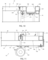
- FIG. 10 is a cross-sectional side elevational view of a handle of the storage assembly taken along the line X-X, FIG. 1 ;
- FIG. 11 is a cross-sectional side elevational view of the storage assembly taken along the line XI-XI, FIG. 1 ;
- FIG. 12 is a cross-sectional side elevational view of the storage assembly taken along the line XII-XII, FIG. 1 .
- the terms “upper,” “lower,” “right,” “left,” “rear,” “front,” “vertical,” “horizontal,” and derivatives thereof shall relate to the invention as oriented in FIGS. 1 and 3 .
- the invention may assume various alternative orientations, except where expressly specified to the contrary.
- the specific devices and processes illustrated in the attached drawings, and described in the following specification are simply exemplary embodiments of the inventive concepts defined in the appended claims. Hence, specific dimensions and other characteristics relating to the embodiments disclosed herein are not to be considered as limiting, unless the claims expressly state otherwise.
- the reference numeral 10 generally designates a storage assembly that may be provided in various configurations ( FIGS. 1 , 2 , 4 and 5 ) each configured to closely interfit with adjacent storage assemblies in a linearly offset or non-linear, end-to-end relationship ( FIGS. 3 and 6 ), such that a plurality of the storage assemblies 10 cooperate to provide a storage arrangement 11 configured to subdivide a given floor workspace area.
- the storage assembly 10 may include a top wall 12 , a bottom wall 14 spaced vertically below the top wall 12 , a pair of internal side walls 16 extending vertically between the top wall 12 and the bottom wall 14 , and a pair of external side walls 18 located outwardly from the internal side walls 16 along the length of the storage assembly 10 .
- the top wall 12 , the bottom wall 14 and the internal side walls 16 may cooperate to define an internal storage space 20 that may be subdivided by various internal components to meet a particular user's requirements, while the internal side walls 16 cooperate with the external side walls 18 to define open spaces 21 therebetween.
- the storage assembly 10 FIGS.
- 1 , 2 , 4 and 5 may include one or more horizontal shelves 22 extending an entire distance between the internal side walls 16 ( FIG. 1 ), one or more vertical partitions 24 ( FIGS. 2 , 4 and 5 ) extending between the top wall 12 and the bottom wall 14 and spaced between the internal side walls 16 , horizontal shelves 26 ( FIGS. 4 and 5 ) extending between one of the internal side walls 16 and a vertical partition 24 and/or between a pair of the vertical partitions 24 , one or more drawers 28 ( FIGS. 2 and 5 ) movable between a retracted position A where the door 28 is received within the interior space 20 and an extended position B where the drawer 28 extends from within the interior storage space 20 , and/or any combination thereof.
- the storage assembly 10 may also include a rear wall 30 that may be secured to the top wall 12 , the bottom wall 14 and/or the interior side walls 16 .
- the storage assembly 10 may also be constructed without the rear wall 30 thereby allowing access to the interior storage space 20 from both sides of the storage assembly 10 .
- One or more shelf support brackets 34 ( FIGS. 7 and 8 ) may support the shelves 22 , 26 at various, pre-selected vertical positions within the interior storage space 20 .
- the shelf support brackets 34 are configured to engage one or more vertical rows of spaced apertures 36 .
- Each support bracket 34 may include a vertical portion 35 , a horizontal shelf-supporting portion 37 , and an outwardly-positioned guide portion 39 configured to abut an edge of the shelf 22 and keep the shelf 22 centered between cooperating support brackets 34 . It is also noted that the configuration of the support brackets 34 that include the guide portion 39 allow the associated shelves 22 , 26 to be supported in an angular or tilted orientation within the interior storage space 20 with the support brackets 34 located at the front of the storage assembly 10 being positioned lower than the support brackets located at the rear of the storage assembly 10 .
- the top wall 12 may include a central portion 38 vertically aligned with the interior storage space 20 , and a pair of opposite end portions 40 extending outward from the central portion 38 beyond the internal side walls 16 .
- the bottom wall 14 may include a central portion 42 vertically aligned with the interior storage space 20 , and a pair of opposite end portions 44 extending outward from the central portion 42 beyond the interior side walls 16 .
- the top wall 12 and the bottom wall 14 may include a single end portion 40 , 44 , respectively.
- Each end portion 40 of the top wall 12 may include an end surface 46
- each end portion 44 of the bottom wall 14 may include an end surface 48 .
- each straight edge portion 50 , 52 extends at an angle ⁇ ( FIG. 3 ) of less than 90° from a centerline or longitudinal axis 54 of the storage assembly 10 . More preferably, each straight edge portion 50 , 52 extends at an angle of less than or equal to about 60° from the longitudinal axis 54 .
- each external side wall 18 may include a plurality of layered components such as an internal structural reinforcement member 58 and an aesthetic external cover member 62 .
- each external side wall 18 includes a pair of end surfaces 64 each including a pair of substantially straight portions 66 each extending from the longitudinal axis 54 of the storage assembly 10 at a similar angle to that as discussed above with respect to the straight edge portions 50 , 52 of the top and bottom walls 12 , 14 .
- the vertical outer edges 70 ( FIGS. 7 and 9 A ) of the internal structural reinforcement member 58 and/or the vertical outer edges 72 of the external cover member 62 may include a curved or structural reinforcement edge 74 , 76 , respectively, to structurally reinforce the external side wall 18 .
- the cover member 62 includes an upper wrap portion 59 that wraps over an upper edge of the reinforcement member 58 , as described below.
- the external side wall further includes a J-shaped clip member 75 secured to the vertical outer edges 72 of the cover member 62 , and J-shaped clip members 77 secured to an inner edge of the upper wrap portion 59 of the cover member 62 .
- Each end portion 40 of the top wall 12 may also include a handle 92 configured so as to be easily gripped by a user to facilitate movement of the storage assembly 10 within a given workspace area.
- the handle 92 is provided as a triangularly-shaped relief 100 extending into the top wall 12 downward from a top surface 102 of the top wall 12 .
- the relief 100 ( FIG. 10 ) may extend completely through the top wall 12 from the top surface 102 through the bottom surface 104 .
- the handle 92 is vertically aligned with the corresponding open space 21 .
- the storage assembly 10 may also include a cap member 106 configured so as to cover a corresponding end portion 40 of the top wall 12 .
- each cap member 106 is triangularly-shaped so as to correspond to the triangle shape of the corresponding end portion 40 , and includes an upwardly-opening relief 108 that is co-aligned with the relief 100 of the corresponding end portion 40 .
- the relief 108 is provided a triangularly-shaped cross-sectional configuration that corresponds to the triangle shape of the relief 100 of the end portion 40 of the top wall 12 , however other cross-sectional configurations of the relief 100 and relief 108 may be utilized.
- Each cap member 106 may also include a bottom wall 110 .
- the cap member 106 is sized such that the cap member 106 extends completely through the relief 100 of the end portion 40 and into the open space 21 between the internal side wall 16 and the external side wall 18 .
- the cap member 106 may be secured to the top wall 12 via a plurality of mechanical fasteners such as screws or bolts 111 threadably received within corresponding bosses 112 integrally molded with the cap member 106 .
- a cover 114 may be positioned within the relief 108 so as to aesthetically cover at least some of the screws 111 , and may be held within the relief 108 via a frictional engagement and/or an adhesive.
- the storage assembly 10 may also include a plurality of caster assemblies 120 secured to and extending downward from the bottom wall 14 and positioned so as to movably support the storage assembly on a floor surface.
- each caster assembly 120 includes a caster mount 122 secured to an underside of the bottom wall 14 via a plurality of mechanical fasteners such as screws 124 , a socket insert 126 press-fit within the corresponding caster mount 122 , and a caster 128 pivotably received within the socket insert 126 .
- the storage assembly 10 may also include a pair of cover members 130 ( FIGS. 1 , 7 and 11 ) configured so as to wrap about the end surface 48 of the lower wall 14 .
- each cover member 130 is provided with an L-shaped cross-sectional configuration including a horizontal bottom portion 132 and a vertical top portion 136 .
- Each cover member 130 may be secured to the bottom surface 121 of the bottom wall 14 via a plurality of mechanical fasteners such as screws 138 extending through the bottom portion 132 and into the bottom wall 14 .
- the storage assembly 10 may further include a pair of frame assemblies 140 positioned within the corresponding open areas 21 .
- the frame assemblies 140 may include an upper frame portion 142 positioned adjacent the top wall 12 , a lower frame portion 144 positioned adjacent the bottom wall 14 , and a plurality of vertical frame members 146 extending between the upper frame portion 142 and the lower frame portion 144 , where the vertical frame members 146 are welded to the upper and lower frame portions 142 , 144 or secured thereto in another suitable manner.
- each frame assembly 140 is positioned between one of the end portions 40 of the top wall 12 and one of the end portions 44 of the bottom wall 14 , and is secured to the top wall 12 and the bottom wall 14 via a plurality of mechanical fasteners such as bolts 152 and nuts 154 where the bolts 152 extend through the top and bottom walls 12 , 14 and the upper and lower frame portions 142 , 144 .
- the external side wall 18 may be placed over the corresponding frame assembly 140 such that the external side wall 18 is also positioned between the end portion 40 of the top wall 12 and the end portion 44 of the bottom wall 14 .
- the cap member 106 includes a flange 107 that extends downwardly below an upper edge of the external side wall 18 , while the top portion 136 of the cover member 30 extends upwardly from a bottom edge of the external side wall 18 , such that the exterior side wall 18 is trapped between the flange 107 of the cap member 106 and the top wall 12 ( FIG. 10 ) and between the top portion 136 of the cover member 130 and the bottom wall 14 when the cap member 106 and the cover member 130 are secured to the top wall 12 and the bottom wall 14 , respectively.
- the J-shaped clip 75 extends over the outer edge 70 of the reinforcement member 58 .
- the upper wrap portion 59 wraps or extends over the upper edge of the reinforcement member 58 and the angular frame portion 149 of the upper frame portion 142 , and the J-shaped clip members 77 are received within elongated aperture 151 of the angular frame portion 149 .
- the top wall 12 is then secured such that the top wall 12 abuts the upper wrap portion 59 thereby tightening the cover member 62 in the vertical direction.
- the frame assemblies 140 may also be configured to support the caster assemblies 120 .
- the caster mount 122 may be secured directly to the lower frame portion 144 of the frame assembly 140 via a mechanical fastener such as a screw 161 and nut 163 .
- the storage assembly 10 may be provided in various configurations.
- the storage assembly 10 may be provided in a relatively straight configuration as shown in FIGS. 1 - 3 , a curved configuration as shown in FIGS. 4 - 6 , or other configurations.
- the forward edge 160 and the rear edge 162 of the top wall 12 , the forward edge 164 and the rearward edge 166 ( FIG. 7 ) of the bottom wall 14 , and the forward edge 168 and the rear edge 170 of the shelves 22 are each substantially straight along the length thereof, while the rear wall 30 is substantially planar.
- FIGS. 1 - 3 the forward edge 160 and the rear edge 162 of the top wall 12 , the forward edge 164 and the rearward edge 166 ( FIG. 7 ) of the bottom wall 14 , and the forward edge 168 and the rear edge 170 of the shelves 22 are each substantially straight along the length thereof, while the rear wall 30 is substantially planar.
- the forward edge 160 and rear edge 162 of the top wall 12 , the forward edge 164 and the rear edge 166 of the bottom wall 14 and the forward edge 168 and the rear edge 170 of each of the shelves 22 may be curved along the length thereof, while the rear wall 30 may be provided in the shape of a curved plane.
- adjacent storage assemblies 10 may be positioned adjacent one another and cooperate to form the storage arrangement 11 .
- adjacent storage assemblies 10 may be positioned with respect to one another such that the straight edge portions 50 of the top wall 12 , the straight edge portions 52 of the bottom wall, the portions 66 of the exterior side walls 18 , the cap member 106 , and/or the cover members 130 of the adjacent storage assemblies in a closely interfit manner as shown in FIGS. 3 and 6 .
- adjacent storage assemblies 10 are configured to closely interfit with one another such that the centerline of adjacent storage assemblies extend at an angle ⁇ of greater than 90° from one another, and more preferably of greater than or equal to about 120° when the storage assemblies 10 are closely interfit with one another.
- the storage arrangement 11 may be formed utilizing storage assemblies of the straight configuration ( FIGS. 1 - 3 ), of the curved configuration ( FIGS. 4 - 6 ), other suitable configurations, or combinations thereof. While the top wall 12 , the bottom wall 14 , the exterior end wall 18 , the cap member 106 and the cover member 130 are each illustrated as including a pair of straight portions or surfaces, it is noted that each of the elements may be configured to include one or more straight portions or surfaces configured such that adjacent storage assemblies 10 may closely interfit with one another in an offset of non-linear, end-to-end relationship so as to divide a given floor workspace area in the manner described above.
- the storage arrangement 11 may also include multiple storage assemblies 10 positioned proximate one another in a linearly offset, end-to-end, daisy chain-type relationship where at least one storage assembly 10 is positioned between two adjacent storage assemblies located at opposite ends thereof.
Landscapes
- Assembled Shelves (AREA)
- Combinations Of Kitchen Furniture (AREA)
- Details Of Rigid Or Semi-Rigid Containers (AREA)
Abstract
Description
Claims (22)
Priority Applications (3)
| Application Number | Priority Date | Filing Date | Title |
|---|---|---|---|
| US16/833,739 US11647835B2 (en) | 2020-03-30 | 2020-03-30 | Storage assembly |
| CN202180010763.2A CN115003457A (en) | 2020-03-30 | 2021-03-30 | Storage assembly |
| PCT/IB2021/052617 WO2021198901A1 (en) | 2020-03-30 | 2021-03-30 | Storage assembly |
Applications Claiming Priority (1)
| Application Number | Priority Date | Filing Date | Title |
|---|---|---|---|
| US16/833,739 US11647835B2 (en) | 2020-03-30 | 2020-03-30 | Storage assembly |
Publications (2)
| Publication Number | Publication Date |
|---|---|
| US20210298471A1 US20210298471A1 (en) | 2021-09-30 |
| US11647835B2 true US11647835B2 (en) | 2023-05-16 |
Family
ID=77854279
Family Applications (1)
| Application Number | Title | Priority Date | Filing Date |
|---|---|---|---|
| US16/833,739 Active US11647835B2 (en) | 2020-03-30 | 2020-03-30 | Storage assembly |
Country Status (3)
| Country | Link |
|---|---|
| US (1) | US11647835B2 (en) |
| CN (1) | CN115003457A (en) |
| WO (1) | WO2021198901A1 (en) |
Citations (114)
| Publication number | Priority date | Publication date | Assignee | Title |
|---|---|---|---|---|
| US790440A (en) * | 1904-07-30 | 1905-05-23 | Henry Klein | Revolving window-shade-display case. |
| US1412895A (en) * | 1920-10-01 | 1922-04-18 | David M Rosenthal | Furniture |
| US1978494A (en) | 1929-11-23 | 1934-10-30 | Junkers Hugo | Hollow structural element |
| GB619191A (en) * | 1948-01-28 | 1949-03-04 | Horace Stanley Hibbit | Improvements in or relating to sectionalised bookcases or cabinets |
| US2496221A (en) | 1946-01-05 | 1950-01-31 | Edward G Koch | Display device |
| US2525208A (en) * | 1946-09-27 | 1950-10-10 | Clink Ray | Sectional tool cabinet |
| US2543263A (en) * | 1947-10-13 | 1951-02-27 | Grand Rapids Store Equip Co | Connected wall store furniture |
| US2721662A (en) | 1952-11-15 | 1955-10-25 | Wright Line Inc | Truck for transporting business machine punched cards |
| US2771334A (en) * | 1953-06-11 | 1956-11-20 | Bennett T Griggs | Portable bar |
| US2995408A (en) * | 1959-05-11 | 1961-08-08 | Kobrin Maurice | Knockdown, prefabricated sectional bar |
| US3257154A (en) * | 1964-03-25 | 1966-06-21 | Robert B Lewis | Container |
| US3450451A (en) * | 1967-08-21 | 1969-06-17 | Granite Mill & Fixture Co | Portable,multiple-use cabinet |
| US3520583A (en) * | 1967-12-14 | 1970-07-14 | John J Case | Tool cabinet |
| US3532403A (en) * | 1968-03-25 | 1970-10-06 | John T Koski | Transportable sectional bar |
| FR2063353A5 (en) * | 1969-10-10 | 1971-07-09 | Rollet Bernard | |
| DE2201642A1 (en) * | 1972-01-14 | 1973-08-02 | Wolff Joachim Dipl Ing | FLOOR FRAME |
| US3931894A (en) * | 1974-01-16 | 1976-01-13 | Murphy Thomas V | Display panel and assembly |
| US3961830A (en) * | 1973-11-26 | 1976-06-08 | Eulit-Werk Staude & Co. Kg | Sales display, in particular for watchband transparent packages |
| DE3225757A1 (en) * | 1982-07-09 | 1984-01-12 | Peter Dipl.-Ing. 3000 Hannover Fuge | Furniture element system |
| DE3241717A1 (en) * | 1982-11-11 | 1984-05-17 | Einkaufszentrale für öffentliche Bibliotheken GmbH, 7410 Reutlingen | Article carrier, especially for books |
| US4548324A (en) * | 1984-01-18 | 1985-10-22 | S & K Products Co. Inc. | Table and literature display stand |
| US4702534A (en) * | 1985-09-16 | 1987-10-27 | Witt Henry C | Winged display case |
| US4786122A (en) | 1986-10-30 | 1988-11-22 | Luxor Corporation | Cabinet construction |
| FR2639527A1 (en) * | 1988-11-28 | 1990-06-01 | Boisson Entreprise | Display unit for displaying articles, especially non-therapeutic chemists' products |
| JPH02220609A (en) | 1989-02-23 | 1990-09-03 | Kokuyo Co Ltd | Wagon |
| US5069466A (en) | 1989-07-14 | 1991-12-03 | Propst Robert L | Cart assembly |
| US5083512A (en) * | 1988-03-01 | 1992-01-28 | Herman Miller, Inc. | Work environment system |
| US5159973A (en) * | 1991-03-28 | 1992-11-03 | Plastics Manufacturing Co. | Dual temperature maintenance food serving compartment with pre-cooled cooling modules and heat storage pellets |
| USD331334S (en) | 1990-03-19 | 1992-12-01 | Herman Miller, Inc. | Storage cabinet |
| DE9403450U1 (en) * | 1994-03-01 | 1994-06-09 | Suter Adolf | Cabinet furniture |
| WO1994015505A1 (en) * | 1991-12-04 | 1994-07-21 | Frederick Hutter | Cuboid component |
| DE9408570U1 (en) * | 1993-10-04 | 1994-09-08 | Linde Ag | Furniture combination |
| DE4319228A1 (en) * | 1993-06-11 | 1994-12-15 | Octanorm Vertriebs Gmbh | Modular display-case system |
| US5405192A (en) * | 1993-12-07 | 1995-04-11 | Mcgrath; Stephen E. | Modular booth display assembly |
| BE1007253A3 (en) * | 1993-06-30 | 1995-05-02 | Wyckaert Carl L R C | Modular storage system |
| USD360725S (en) | 1994-07-07 | 1995-07-25 | Rubbermaid Office Products Inc. | Book cart |
| USD361643S (en) | 1994-07-07 | 1995-08-22 | Rubbermaid Office Products Inc. | In-house mail delivery cart |
| USD361681S (en) | 1993-06-03 | 1995-08-29 | Over-Panel Technology, Ltd. | Panel cap for a display panel |
| USD365944S (en) | 1994-08-29 | 1996-01-09 | Blockbuster Entertainment Corp. | Cabinet counter |
| US5566961A (en) | 1994-07-11 | 1996-10-22 | Rubbermaid Office Products Inc. | Modular storage unit |
| EP0744141A2 (en) * | 1995-05-22 | 1996-11-27 | Paul Schulz | Element for modular furniture system |
| USD376282S (en) | 1995-08-28 | 1996-12-10 | Smith System Inc | Shelving end panel of sectioned cylindrical plates |
| FR2734998A1 (en) * | 1995-06-08 | 1996-12-13 | Francois Henri Cathala | COMBINATION OF A JOINT SYSTEM WITH AT LEAST 2 MODULAR ELEMENTS |
| US5588541A (en) * | 1994-10-05 | 1996-12-31 | Alco Industries, Inc. | Heavy-duty decorative shelving |
| DE29617605U1 (en) * | 1996-10-08 | 1997-02-06 | Missler Juliane | Curved shelf wall |
| US5634649A (en) | 1993-07-22 | 1997-06-03 | Adolf Wurth Gmbh & Co. Kg | Means for making ready tools and material |
| USD382146S (en) | 1996-08-09 | 1997-08-12 | Hal Sandy | End panel for shelving |
| US5702166A (en) * | 1995-06-09 | 1997-12-30 | Lockheed Martin Corporation | Information kiosks |
| DE29801612U1 (en) * | 1998-01-22 | 1998-03-26 | Elsner Herbert | Mobile counter connector and counter combination |
| USD399377S (en) | 1997-01-21 | 1998-10-13 | The Mead Corporation | Element of a merchandising device |
| USD405616S (en) | 1997-09-05 | 1999-02-16 | Teknion Furniture Systems | Office end panel |
| USD409019S (en) | 1997-04-25 | 1999-05-04 | Teknion Furniture Systems | Mobile storage shelf |
| USD410807S (en) | 1998-01-23 | 1999-06-08 | Jeffery Fear | Pair of side panels for furniture |
| EP0947150A1 (en) | 1998-02-25 | 1999-10-06 | Steelcase Strafor | Multi-functional planar part used as a base and top for a mobile storage unit |
| DE29917874U1 (en) * | 1999-10-08 | 1999-12-30 | Knofe Jens | Sectional furniture set |
| US6155435A (en) * | 1999-02-16 | 2000-12-05 | Malik; Vijay S. | Media storage or display assembly modular media storage units and movable shelves therefor and methods of making the same |
| US6202867B1 (en) * | 1999-01-04 | 2001-03-20 | Terry Store - Age S.P.A. | Modular structure with modular component parts for making shelves and closets |
| US6209977B1 (en) | 1999-06-04 | 2001-04-03 | Global Contract Limited Partnership, An Ontario Limited Partnership | Mobile work station |
| US6267462B1 (en) * | 1998-03-20 | 2001-07-31 | Helge Krause | Cabinet system |
| USD445984S1 (en) | 2000-09-11 | 2001-07-31 | Contico International, Llc | Laundry cart |
| US6341511B1 (en) * | 1997-11-19 | 2002-01-29 | Stanley Mechanics Tools, Inc. | Workstation lock system |
| USD460877S1 (en) | 2001-01-09 | 2002-07-30 | Formway Furniture Limited | Storage unit |
| US6443542B1 (en) | 2000-05-23 | 2002-09-03 | Compaq Computer Corporation | Cabinet system and method of assembling same |
| US6460950B2 (en) | 2000-03-15 | 2002-10-08 | Christopher G. Spitzer | Modular container/bookshelf moving cart |
| USD472689S1 (en) | 2002-01-25 | 2003-04-01 | Smead Manufacturing Company | Rolling cart panel |
| US20030173877A1 (en) * | 2002-03-13 | 2003-09-18 | Pleiman Brian Ralph | Corner storage container |
| US6692011B2 (en) | 2000-10-16 | 2004-02-17 | Steelcase Development Corporation | Mobile pedestal with storable handle |
| US20040119382A1 (en) * | 2002-10-01 | 2004-06-24 | Wenger Corporation | Rehearsal resource center |
| US6776464B2 (en) | 2001-03-21 | 2004-08-17 | Rittal Rcs Communication Systems Gmbh & Co. Kg | Switchgear cabinet including framework and covering members |
| US6824231B2 (en) | 2002-11-22 | 2004-11-30 | Smed International | Storage cabinet |
| USD501285S1 (en) | 2003-10-27 | 2005-01-25 | Coy M. Long, Jr. | Mobile tool cart |
| US20050051108A1 (en) * | 2003-09-09 | 2005-03-10 | Kitty Kingdom, Inc. | Pet playhouse |
| US20050140106A1 (en) | 2003-12-24 | 2005-06-30 | Professional Tool Products, Llc | Service cart with protective bumpers and recessed drawer handles |
| DE102004037138A1 (en) * | 2004-07-30 | 2006-03-23 | Präkelt, Daniel | Modular furniture system has one C-shaped module made up of trapezium-shaped section with equilateral triangles at either end of its longest side and other polygonal modules |
| US7131544B1 (en) * | 2003-07-09 | 2006-11-07 | Long-Stanton Manufacturing Co., Inc. | Wall conforming wine rack for a plurality of bottles |
| US7172094B2 (en) * | 2002-07-01 | 2007-02-06 | Tomy Company, Ltd. | Packaged goods delivering device |
| US7174851B2 (en) * | 2004-08-10 | 2007-02-13 | North America Pet Products | Animal display and habitat assembly |
| US20070152546A1 (en) * | 2005-12-02 | 2007-07-05 | Scott Sallinger | Furniture with modular corner system |
| US20070252489A1 (en) * | 2004-08-09 | 2007-11-01 | Schulz Edward W | Multi-faceted electronic video display structure for organizing and displaying electronic device components |
| US7325891B1 (en) | 2006-04-03 | 2008-02-05 | Bretford Manufacturing, Inc. | Computer cart |
| FR2906447A1 (en) * | 2006-09-28 | 2008-04-04 | Armortech Sa | Modular furniture assembly for forming shelf in bakery shop, has cabinets and furniture continuously placed by assembling connectors at refrigerated cabinet`s wings and placing central portion of dry cabinet`s wings against connectors` edge |
| US7354120B2 (en) * | 2003-08-13 | 2008-04-08 | Original Ideas, Inc. | Portable bar with portable barbecue |
| US20080237322A1 (en) | 2007-03-27 | 2008-10-02 | Chris Mittelstaedt | Storage container |
| US7434819B1 (en) * | 2005-01-12 | 2008-10-14 | Dunavin Brian S | Portable work area |
| US7544915B2 (en) * | 2004-03-31 | 2009-06-09 | The Boeing Company | Aircraft galley carts and associated methods of manufacture |
| US7654399B2 (en) * | 2004-03-19 | 2010-02-02 | Target Brands, Inc. | Configurable display system and modular display arrangement for consumer electronic devices |
| US20100245999A1 (en) | 2009-03-30 | 2010-09-30 | Carlow Richard A | Cart For 3D Glasses |
| US20110068562A1 (en) | 2009-09-18 | 2011-03-24 | Keffeler Mark G | Medication cart |
| US7950679B2 (en) * | 2007-06-25 | 2011-05-31 | Joseph Claffy | Insulated food tray wagon |
| US8123311B2 (en) * | 2008-04-23 | 2012-02-28 | Robert Nilsson | Portable display system and associated methods |
| US8157337B2 (en) * | 2009-06-16 | 2012-04-17 | Edwin Dizon Manalang | Tool box storage assembly |
| USD661512S1 (en) | 2011-02-18 | 2012-06-12 | Rubbermaid Incorporated | Mobile cabinet |
| US8322732B2 (en) | 2006-06-16 | 2012-12-04 | Bradyquin, Llc | Portable workstation |
| US8419140B2 (en) * | 2008-10-28 | 2013-04-16 | John William Ward | Chambered cremation URN memorial with attached or integrated electronic imaging device |
| US20130186844A1 (en) * | 2012-01-20 | 2013-07-25 | Parker House Mfg Co., Inc. | Removable pilaster bookcase extension system |
| US8684552B2 (en) * | 2012-07-11 | 2014-04-01 | Agio International Company, Ltd | Lighted furniture assembly |
| US8708168B2 (en) * | 2011-11-02 | 2014-04-29 | Pard Hardware Industrial Co., Ltd. | Tool stand |
| US20140166516A1 (en) | 2012-12-19 | 2014-06-19 | Milwaukee Electric Tool Corporation | Tool storage devices |
| USD726987S1 (en) | 2013-10-22 | 2015-04-14 | Whitmor, Inc | Side support for a cart |
| US9079596B2 (en) | 2013-04-04 | 2015-07-14 | Hms Mfg. Co. | Cart and drawer assembly |
| US9084480B2 (en) * | 2012-10-01 | 2015-07-21 | Erin L. Atwood | Storage and transport case for jewelry and accessories |
| US20150285531A1 (en) | 2014-04-05 | 2015-10-08 | Lg Electronics Inc. | Dehumidifier |
| US20150320207A1 (en) * | 2014-01-14 | 2015-11-12 | Kao-Fu Chan | Bookcase |
| US20160143456A1 (en) * | 2014-11-25 | 2016-05-26 | Wowthyguest, Inc. | Display system for bulk food items and related methods |
| US20160262842A1 (en) * | 2015-03-09 | 2016-09-15 | Variamed Llc | Modular surgical accessory table |
| US9456688B2 (en) * | 2014-10-01 | 2016-10-04 | Kmc Holdings, Llc | Modular storage and work station |
| JP2017086432A (en) | 2015-11-09 | 2017-05-25 | 株式会社岡村製作所 | Article storage furniture |
| US9730517B2 (en) | 2015-05-27 | 2017-08-15 | Steelcase Inc. | Storage assembly with pull-out arrangement |
| FR3054420A1 (en) | 2016-07-29 | 2018-02-02 | Jec Solutions | FURNITURE COMPRISING A CAISSON AND A MOBILE CASE |
| US9936806B2 (en) * | 2014-12-23 | 2018-04-10 | James Earl Taylor, JR. | Storage chest |
| US20180334270A1 (en) | 2013-03-22 | 2018-11-22 | Snap-On Incorporated | Floor jack with temporary shipping handles and packaging therefor |
| US10174515B1 (en) * | 2016-05-06 | 2019-01-08 | Daniel John Krivens | Semi-private desk and meeting area |
| US10178908B1 (en) * | 2018-09-19 | 2019-01-15 | Chin Jwu Enterprise Co., Ltd. | Storage rack |
| EP3400830B1 (en) * | 2017-05-12 | 2019-12-18 | HORST Retail Concepts GmbH | Shelving system |
-
2020
- 2020-03-30 US US16/833,739 patent/US11647835B2/en active Active
-
2021
- 2021-03-30 CN CN202180010763.2A patent/CN115003457A/en active Pending
- 2021-03-30 WO PCT/IB2021/052617 patent/WO2021198901A1/en active Application Filing
Patent Citations (114)
| Publication number | Priority date | Publication date | Assignee | Title |
|---|---|---|---|---|
| US790440A (en) * | 1904-07-30 | 1905-05-23 | Henry Klein | Revolving window-shade-display case. |
| US1412895A (en) * | 1920-10-01 | 1922-04-18 | David M Rosenthal | Furniture |
| US1978494A (en) | 1929-11-23 | 1934-10-30 | Junkers Hugo | Hollow structural element |
| US2496221A (en) | 1946-01-05 | 1950-01-31 | Edward G Koch | Display device |
| US2525208A (en) * | 1946-09-27 | 1950-10-10 | Clink Ray | Sectional tool cabinet |
| US2543263A (en) * | 1947-10-13 | 1951-02-27 | Grand Rapids Store Equip Co | Connected wall store furniture |
| GB619191A (en) * | 1948-01-28 | 1949-03-04 | Horace Stanley Hibbit | Improvements in or relating to sectionalised bookcases or cabinets |
| US2721662A (en) | 1952-11-15 | 1955-10-25 | Wright Line Inc | Truck for transporting business machine punched cards |
| US2771334A (en) * | 1953-06-11 | 1956-11-20 | Bennett T Griggs | Portable bar |
| US2995408A (en) * | 1959-05-11 | 1961-08-08 | Kobrin Maurice | Knockdown, prefabricated sectional bar |
| US3257154A (en) * | 1964-03-25 | 1966-06-21 | Robert B Lewis | Container |
| US3450451A (en) * | 1967-08-21 | 1969-06-17 | Granite Mill & Fixture Co | Portable,multiple-use cabinet |
| US3520583A (en) * | 1967-12-14 | 1970-07-14 | John J Case | Tool cabinet |
| US3532403A (en) * | 1968-03-25 | 1970-10-06 | John T Koski | Transportable sectional bar |
| FR2063353A5 (en) * | 1969-10-10 | 1971-07-09 | Rollet Bernard | |
| DE2201642A1 (en) * | 1972-01-14 | 1973-08-02 | Wolff Joachim Dipl Ing | FLOOR FRAME |
| US3961830A (en) * | 1973-11-26 | 1976-06-08 | Eulit-Werk Staude & Co. Kg | Sales display, in particular for watchband transparent packages |
| US3931894A (en) * | 1974-01-16 | 1976-01-13 | Murphy Thomas V | Display panel and assembly |
| DE3225757A1 (en) * | 1982-07-09 | 1984-01-12 | Peter Dipl.-Ing. 3000 Hannover Fuge | Furniture element system |
| DE3241717A1 (en) * | 1982-11-11 | 1984-05-17 | Einkaufszentrale für öffentliche Bibliotheken GmbH, 7410 Reutlingen | Article carrier, especially for books |
| US4548324A (en) * | 1984-01-18 | 1985-10-22 | S & K Products Co. Inc. | Table and literature display stand |
| US4702534A (en) * | 1985-09-16 | 1987-10-27 | Witt Henry C | Winged display case |
| US4786122A (en) | 1986-10-30 | 1988-11-22 | Luxor Corporation | Cabinet construction |
| US5083512A (en) * | 1988-03-01 | 1992-01-28 | Herman Miller, Inc. | Work environment system |
| FR2639527A1 (en) * | 1988-11-28 | 1990-06-01 | Boisson Entreprise | Display unit for displaying articles, especially non-therapeutic chemists' products |
| JPH02220609A (en) | 1989-02-23 | 1990-09-03 | Kokuyo Co Ltd | Wagon |
| US5069466A (en) | 1989-07-14 | 1991-12-03 | Propst Robert L | Cart assembly |
| USD331334S (en) | 1990-03-19 | 1992-12-01 | Herman Miller, Inc. | Storage cabinet |
| US5159973A (en) * | 1991-03-28 | 1992-11-03 | Plastics Manufacturing Co. | Dual temperature maintenance food serving compartment with pre-cooled cooling modules and heat storage pellets |
| WO1994015505A1 (en) * | 1991-12-04 | 1994-07-21 | Frederick Hutter | Cuboid component |
| USD361681S (en) | 1993-06-03 | 1995-08-29 | Over-Panel Technology, Ltd. | Panel cap for a display panel |
| DE4319228A1 (en) * | 1993-06-11 | 1994-12-15 | Octanorm Vertriebs Gmbh | Modular display-case system |
| BE1007253A3 (en) * | 1993-06-30 | 1995-05-02 | Wyckaert Carl L R C | Modular storage system |
| US5634649A (en) | 1993-07-22 | 1997-06-03 | Adolf Wurth Gmbh & Co. Kg | Means for making ready tools and material |
| DE9408570U1 (en) * | 1993-10-04 | 1994-09-08 | Linde Ag | Furniture combination |
| US5405192A (en) * | 1993-12-07 | 1995-04-11 | Mcgrath; Stephen E. | Modular booth display assembly |
| DE9403450U1 (en) * | 1994-03-01 | 1994-06-09 | Suter Adolf | Cabinet furniture |
| USD360725S (en) | 1994-07-07 | 1995-07-25 | Rubbermaid Office Products Inc. | Book cart |
| USD361643S (en) | 1994-07-07 | 1995-08-22 | Rubbermaid Office Products Inc. | In-house mail delivery cart |
| US5566961A (en) | 1994-07-11 | 1996-10-22 | Rubbermaid Office Products Inc. | Modular storage unit |
| USD365944S (en) | 1994-08-29 | 1996-01-09 | Blockbuster Entertainment Corp. | Cabinet counter |
| US5588541A (en) * | 1994-10-05 | 1996-12-31 | Alco Industries, Inc. | Heavy-duty decorative shelving |
| EP0744141A2 (en) * | 1995-05-22 | 1996-11-27 | Paul Schulz | Element for modular furniture system |
| FR2734998A1 (en) * | 1995-06-08 | 1996-12-13 | Francois Henri Cathala | COMBINATION OF A JOINT SYSTEM WITH AT LEAST 2 MODULAR ELEMENTS |
| US5702166A (en) * | 1995-06-09 | 1997-12-30 | Lockheed Martin Corporation | Information kiosks |
| USD376282S (en) | 1995-08-28 | 1996-12-10 | Smith System Inc | Shelving end panel of sectioned cylindrical plates |
| USD382146S (en) | 1996-08-09 | 1997-08-12 | Hal Sandy | End panel for shelving |
| DE29617605U1 (en) * | 1996-10-08 | 1997-02-06 | Missler Juliane | Curved shelf wall |
| USD399377S (en) | 1997-01-21 | 1998-10-13 | The Mead Corporation | Element of a merchandising device |
| USD409019S (en) | 1997-04-25 | 1999-05-04 | Teknion Furniture Systems | Mobile storage shelf |
| USD405616S (en) | 1997-09-05 | 1999-02-16 | Teknion Furniture Systems | Office end panel |
| US6341511B1 (en) * | 1997-11-19 | 2002-01-29 | Stanley Mechanics Tools, Inc. | Workstation lock system |
| DE29801612U1 (en) * | 1998-01-22 | 1998-03-26 | Elsner Herbert | Mobile counter connector and counter combination |
| USD410807S (en) | 1998-01-23 | 1999-06-08 | Jeffery Fear | Pair of side panels for furniture |
| EP0947150A1 (en) | 1998-02-25 | 1999-10-06 | Steelcase Strafor | Multi-functional planar part used as a base and top for a mobile storage unit |
| US6267462B1 (en) * | 1998-03-20 | 2001-07-31 | Helge Krause | Cabinet system |
| US6202867B1 (en) * | 1999-01-04 | 2001-03-20 | Terry Store - Age S.P.A. | Modular structure with modular component parts for making shelves and closets |
| US6155435A (en) * | 1999-02-16 | 2000-12-05 | Malik; Vijay S. | Media storage or display assembly modular media storage units and movable shelves therefor and methods of making the same |
| US6209977B1 (en) | 1999-06-04 | 2001-04-03 | Global Contract Limited Partnership, An Ontario Limited Partnership | Mobile work station |
| DE29917874U1 (en) * | 1999-10-08 | 1999-12-30 | Knofe Jens | Sectional furniture set |
| US6460950B2 (en) | 2000-03-15 | 2002-10-08 | Christopher G. Spitzer | Modular container/bookshelf moving cart |
| US6443542B1 (en) | 2000-05-23 | 2002-09-03 | Compaq Computer Corporation | Cabinet system and method of assembling same |
| USD445984S1 (en) | 2000-09-11 | 2001-07-31 | Contico International, Llc | Laundry cart |
| US6692011B2 (en) | 2000-10-16 | 2004-02-17 | Steelcase Development Corporation | Mobile pedestal with storable handle |
| USD460877S1 (en) | 2001-01-09 | 2002-07-30 | Formway Furniture Limited | Storage unit |
| US6776464B2 (en) | 2001-03-21 | 2004-08-17 | Rittal Rcs Communication Systems Gmbh & Co. Kg | Switchgear cabinet including framework and covering members |
| USD472689S1 (en) | 2002-01-25 | 2003-04-01 | Smead Manufacturing Company | Rolling cart panel |
| US20030173877A1 (en) * | 2002-03-13 | 2003-09-18 | Pleiman Brian Ralph | Corner storage container |
| US7172094B2 (en) * | 2002-07-01 | 2007-02-06 | Tomy Company, Ltd. | Packaged goods delivering device |
| US20040119382A1 (en) * | 2002-10-01 | 2004-06-24 | Wenger Corporation | Rehearsal resource center |
| US6824231B2 (en) | 2002-11-22 | 2004-11-30 | Smed International | Storage cabinet |
| US7131544B1 (en) * | 2003-07-09 | 2006-11-07 | Long-Stanton Manufacturing Co., Inc. | Wall conforming wine rack for a plurality of bottles |
| US7354120B2 (en) * | 2003-08-13 | 2008-04-08 | Original Ideas, Inc. | Portable bar with portable barbecue |
| US20050051108A1 (en) * | 2003-09-09 | 2005-03-10 | Kitty Kingdom, Inc. | Pet playhouse |
| USD501285S1 (en) | 2003-10-27 | 2005-01-25 | Coy M. Long, Jr. | Mobile tool cart |
| US20050140106A1 (en) | 2003-12-24 | 2005-06-30 | Professional Tool Products, Llc | Service cart with protective bumpers and recessed drawer handles |
| US7654399B2 (en) * | 2004-03-19 | 2010-02-02 | Target Brands, Inc. | Configurable display system and modular display arrangement for consumer electronic devices |
| US7544915B2 (en) * | 2004-03-31 | 2009-06-09 | The Boeing Company | Aircraft galley carts and associated methods of manufacture |
| DE102004037138A1 (en) * | 2004-07-30 | 2006-03-23 | Präkelt, Daniel | Modular furniture system has one C-shaped module made up of trapezium-shaped section with equilateral triangles at either end of its longest side and other polygonal modules |
| US20070252489A1 (en) * | 2004-08-09 | 2007-11-01 | Schulz Edward W | Multi-faceted electronic video display structure for organizing and displaying electronic device components |
| US7174851B2 (en) * | 2004-08-10 | 2007-02-13 | North America Pet Products | Animal display and habitat assembly |
| US7434819B1 (en) * | 2005-01-12 | 2008-10-14 | Dunavin Brian S | Portable work area |
| US20070152546A1 (en) * | 2005-12-02 | 2007-07-05 | Scott Sallinger | Furniture with modular corner system |
| US7325891B1 (en) | 2006-04-03 | 2008-02-05 | Bretford Manufacturing, Inc. | Computer cart |
| US8322732B2 (en) | 2006-06-16 | 2012-12-04 | Bradyquin, Llc | Portable workstation |
| FR2906447A1 (en) * | 2006-09-28 | 2008-04-04 | Armortech Sa | Modular furniture assembly for forming shelf in bakery shop, has cabinets and furniture continuously placed by assembling connectors at refrigerated cabinet`s wings and placing central portion of dry cabinet`s wings against connectors` edge |
| US20080237322A1 (en) | 2007-03-27 | 2008-10-02 | Chris Mittelstaedt | Storage container |
| US7950679B2 (en) * | 2007-06-25 | 2011-05-31 | Joseph Claffy | Insulated food tray wagon |
| US8123311B2 (en) * | 2008-04-23 | 2012-02-28 | Robert Nilsson | Portable display system and associated methods |
| US8419140B2 (en) * | 2008-10-28 | 2013-04-16 | John William Ward | Chambered cremation URN memorial with attached or integrated electronic imaging device |
| US20100245999A1 (en) | 2009-03-30 | 2010-09-30 | Carlow Richard A | Cart For 3D Glasses |
| US8157337B2 (en) * | 2009-06-16 | 2012-04-17 | Edwin Dizon Manalang | Tool box storage assembly |
| US20110068562A1 (en) | 2009-09-18 | 2011-03-24 | Keffeler Mark G | Medication cart |
| USD661512S1 (en) | 2011-02-18 | 2012-06-12 | Rubbermaid Incorporated | Mobile cabinet |
| US8708168B2 (en) * | 2011-11-02 | 2014-04-29 | Pard Hardware Industrial Co., Ltd. | Tool stand |
| US20130186844A1 (en) * | 2012-01-20 | 2013-07-25 | Parker House Mfg Co., Inc. | Removable pilaster bookcase extension system |
| US8684552B2 (en) * | 2012-07-11 | 2014-04-01 | Agio International Company, Ltd | Lighted furniture assembly |
| US9084480B2 (en) * | 2012-10-01 | 2015-07-21 | Erin L. Atwood | Storage and transport case for jewelry and accessories |
| US20140166516A1 (en) | 2012-12-19 | 2014-06-19 | Milwaukee Electric Tool Corporation | Tool storage devices |
| US20180334270A1 (en) | 2013-03-22 | 2018-11-22 | Snap-On Incorporated | Floor jack with temporary shipping handles and packaging therefor |
| US9079596B2 (en) | 2013-04-04 | 2015-07-14 | Hms Mfg. Co. | Cart and drawer assembly |
| USD726987S1 (en) | 2013-10-22 | 2015-04-14 | Whitmor, Inc | Side support for a cart |
| US20150320207A1 (en) * | 2014-01-14 | 2015-11-12 | Kao-Fu Chan | Bookcase |
| US20150285531A1 (en) | 2014-04-05 | 2015-10-08 | Lg Electronics Inc. | Dehumidifier |
| US9456688B2 (en) * | 2014-10-01 | 2016-10-04 | Kmc Holdings, Llc | Modular storage and work station |
| US20160143456A1 (en) * | 2014-11-25 | 2016-05-26 | Wowthyguest, Inc. | Display system for bulk food items and related methods |
| US9936806B2 (en) * | 2014-12-23 | 2018-04-10 | James Earl Taylor, JR. | Storage chest |
| US20160262842A1 (en) * | 2015-03-09 | 2016-09-15 | Variamed Llc | Modular surgical accessory table |
| US9730517B2 (en) | 2015-05-27 | 2017-08-15 | Steelcase Inc. | Storage assembly with pull-out arrangement |
| JP2017086432A (en) | 2015-11-09 | 2017-05-25 | 株式会社岡村製作所 | Article storage furniture |
| US10174515B1 (en) * | 2016-05-06 | 2019-01-08 | Daniel John Krivens | Semi-private desk and meeting area |
| FR3054420A1 (en) | 2016-07-29 | 2018-02-02 | Jec Solutions | FURNITURE COMPRISING A CAISSON AND A MOBILE CASE |
| EP3400830B1 (en) * | 2017-05-12 | 2019-12-18 | HORST Retail Concepts GmbH | Shelving system |
| US10178908B1 (en) * | 2018-09-19 | 2019-01-15 | Chin Jwu Enterprise Co., Ltd. | Storage rack |
Non-Patent Citations (1)
| Title |
|---|
| ISA/US; International Search Report; dated May 19, 2021; Entire document. |
Also Published As
| Publication number | Publication date |
|---|---|
| US20210298471A1 (en) | 2021-09-30 |
| WO2021198901A1 (en) | 2021-10-07 |
| CN115003457A (en) | 2022-09-02 |
Similar Documents
| Publication | Publication Date | Title |
|---|---|---|
| US7832571B2 (en) | Shelving system | |
| US9198513B2 (en) | Adjustable shelf and method of use | |
| US5829767A (en) | Knock-down cart | |
| US9314919B2 (en) | Truck box with reinforced lid | |
| USD471033S1 (en) | Multiple-shelf wagon for storage and transport | |
| US20090108612A1 (en) | Vehicle tailgate enclosure with enhanced adjustment | |
| WO2008109655A2 (en) | Table | |
| US20020130598A1 (en) | Industrial tool chest with modular shelving | |
| USD974808S1 (en) | Swivel to open standing shelf | |
| USD979298S1 (en) | Display rack with shelves | |
| USD974087S1 (en) | Modular display rack with shelves | |
| JP2017523846A (en) | A container with a drawer | |
| US5518288A (en) | Multiple configuration cargo system for pickup trucks | |
| JP2644519B2 (en) | Device door with stiffened inner plate with shelves | |
| US5102180A (en) | Vehicle cover with sideways accessible storage container | |
| US11647835B2 (en) | Storage assembly | |
| AU2014201414B2 (en) | Shelf structure for a merchandiser | |
| US20050206280A1 (en) | Stoage Cabinet With Improved Features | |
| JPH0994775A (en) | Tool box and one-piece bottom panel | |
| JPH0428304A (en) | Desk | |
| MXPA06008766A (en) | Cantilever shelving for utility shed. | |
| US6386610B1 (en) | Movable shelf device for a van | |
| JP3386773B2 (en) | Movable prefabricated store | |
| KR200481983Y1 (en) | A Sectional Furniture | |
| USD1019774S1 (en) | Storage rack |
Legal Events
| Date | Code | Title | Description |
|---|---|---|---|
| FEPP | Fee payment procedure |
Free format text: ENTITY STATUS SET TO UNDISCOUNTED (ORIGINAL EVENT CODE: BIG.); ENTITY STATUS OF PATENT OWNER: LARGE ENTITY |
|
| STPP | Information on status: patent application and granting procedure in general |
Free format text: RESPONSE TO NON-FINAL OFFICE ACTION ENTERED AND FORWARDED TO EXAMINER |
|
| STPP | Information on status: patent application and granting procedure in general |
Free format text: FINAL REJECTION MAILED |
|
| STPP | Information on status: patent application and granting procedure in general |
Free format text: ADVISORY ACTION MAILED |
|
| STPP | Information on status: patent application and granting procedure in general |
Free format text: DOCKETED NEW CASE - READY FOR EXAMINATION |
|
| AS | Assignment |
Owner name: SMITH SYSTEM MANUFACTURING COMPANY, INC., TEXAS Free format text: ASSIGNMENT OF ASSIGNORS INTEREST;ASSIGNORS:WILLIAMS, DAVID;CARR, ROGER JOHN;RISDALL, MICHAEL;AND OTHERS;SIGNING DATES FROM 20200325 TO 20200326;REEL/FRAME:059955/0513 |
|
| STPP | Information on status: patent application and granting procedure in general |
Free format text: NON FINAL ACTION MAILED |
|
| STPP | Information on status: patent application and granting procedure in general |
Free format text: RESPONSE TO NON-FINAL OFFICE ACTION ENTERED AND FORWARDED TO EXAMINER |
|
| AS | Assignment |
Owner name: SMITH SYSTEM MANUFACTURING COMPANY, TEXAS Free format text: CORRECTIVE ASSIGNMENT TO CORRECT THE ASSIGNEE NAME PREVIOUSLY RECORDED AT REEL: 059955 FRAME: 0513. ASSIGNOR(S) HEREBY CONFIRMS THE ASSIGNMENT;ASSIGNORS:WILLIAMS, DAVID;CARR, ROGER JOHN;RISDALL, MICHAEL;AND OTHERS;SIGNING DATES FROM 20200325 TO 20200326;REEL/FRAME:062493/0567 |
|
| STCF | Information on status: patent grant |
Free format text: PATENTED CASE |
|
| CC | Certificate of correction |