US11619082B2 - Monopole door hinges and assemblies - Google Patents
Monopole door hinges and assemblies Download PDFInfo
- Publication number
- US11619082B2 US11619082B2 US16/885,974 US202016885974A US11619082B2 US 11619082 B2 US11619082 B2 US 11619082B2 US 202016885974 A US202016885974 A US 202016885974A US 11619082 B2 US11619082 B2 US 11619082B2
- Authority
- US
- United States
- Prior art keywords
- door
- monopole
- hinge
- interior surface
- supporting portion
- Prior art date
- Legal status (The legal status is an assumption and is not a legal conclusion. Google has not performed a legal analysis and makes no representation as to the accuracy of the status listed.)
- Active, expires
Links
- 230000005404 monopole Effects 0.000 title claims abstract description 90
- 230000000712 assembly Effects 0.000 title description 4
- 238000000429 assembly Methods 0.000 title description 4
- 238000003466 welding Methods 0.000 claims description 7
- 229920000515 polycarbonate Polymers 0.000 claims description 2
- 239000004417 polycarbonate Substances 0.000 claims description 2
- 239000000463 material Substances 0.000 description 4
- 230000008901 benefit Effects 0.000 description 3
- 238000005452 bending Methods 0.000 description 2
- 238000010276 construction Methods 0.000 description 2
- 238000009434 installation Methods 0.000 description 2
- 238000012986 modification Methods 0.000 description 2
- 230000004048 modification Effects 0.000 description 2
- 229910000831 Steel Inorganic materials 0.000 description 1
- 239000011248 coating agent Substances 0.000 description 1
- 238000000576 coating method Methods 0.000 description 1
- 238000000034 method Methods 0.000 description 1
- 239000010959 steel Substances 0.000 description 1
Images


Classifications
-
- H—ELECTRICITY
- H01—ELECTRIC ELEMENTS
- H01Q—ANTENNAS, i.e. RADIO AERIALS
- H01Q1/00—Details of, or arrangements associated with, antennas
- H01Q1/12—Supports; Mounting means
- H01Q1/1242—Rigid masts specially adapted for supporting an aerial
-
- E—FIXED CONSTRUCTIONS
- E05—LOCKS; KEYS; WINDOW OR DOOR FITTINGS; SAFES
- E05D—HINGES OR SUSPENSION DEVICES FOR DOORS, WINDOWS OR WINGS
- E05D3/00—Hinges with pins
- E05D3/02—Hinges with pins with one pin
-
- E—FIXED CONSTRUCTIONS
- E04—BUILDING
- E04H—BUILDINGS OR LIKE STRUCTURES FOR PARTICULAR PURPOSES; SWIMMING OR SPLASH BATHS OR POOLS; MASTS; FENCING; TENTS OR CANOPIES, IN GENERAL
- E04H12/00—Towers; Masts or poles; Chimney stacks; Water-towers; Methods of erecting such structures
- E04H12/003—Access covers or locks therefor
-
- E—FIXED CONSTRUCTIONS
- E04—BUILDING
- E04H—BUILDINGS OR LIKE STRUCTURES FOR PARTICULAR PURPOSES; SWIMMING OR SPLASH BATHS OR POOLS; MASTS; FENCING; TENTS OR CANOPIES, IN GENERAL
- E04H12/00—Towers; Masts or poles; Chimney stacks; Water-towers; Methods of erecting such structures
- E04H12/02—Structures made of specified materials
- E04H12/08—Structures made of specified materials of metal
-
- E—FIXED CONSTRUCTIONS
- E05—LOCKS; KEYS; WINDOW OR DOOR FITTINGS; SAFES
- E05D—HINGES OR SUSPENSION DEVICES FOR DOORS, WINDOWS OR WINGS
- E05D5/00—Construction of single parts, e.g. the parts for attachment
- E05D5/02—Parts for attachment, e.g. flaps
- E05D5/06—Bent flaps
-
- E—FIXED CONSTRUCTIONS
- E05—LOCKS; KEYS; WINDOW OR DOOR FITTINGS; SAFES
- E05D—HINGES OR SUSPENSION DEVICES FOR DOORS, WINDOWS OR WINGS
- E05D5/00—Construction of single parts, e.g. the parts for attachment
- E05D5/02—Parts for attachment, e.g. flaps
- E05D5/06—Bent flaps
- E05D2005/067—Bent flaps gooseneck shaped
-
- E—FIXED CONSTRUCTIONS
- E05—LOCKS; KEYS; WINDOW OR DOOR FITTINGS; SAFES
- E05Y—INDEXING SCHEME ASSOCIATED WITH SUBCLASSES E05D AND E05F, RELATING TO CONSTRUCTION ELEMENTS, ELECTRIC CONTROL, POWER SUPPLY, POWER SIGNAL OR TRANSMISSION, USER INTERFACES, MOUNTING OR COUPLING, DETAILS, ACCESSORIES, AUXILIARY OPERATIONS NOT OTHERWISE PROVIDED FOR, APPLICATION THEREOF
- E05Y2600/00—Mounting or coupling arrangements for elements provided for in this subclass
- E05Y2600/50—Mounting methods; Positioning
- E05Y2600/54—Welding
-
- E—FIXED CONSTRUCTIONS
- E05—LOCKS; KEYS; WINDOW OR DOOR FITTINGS; SAFES
- E05Y—INDEXING SCHEME ASSOCIATED WITH SUBCLASSES E05D AND E05F, RELATING TO CONSTRUCTION ELEMENTS, ELECTRIC CONTROL, POWER SUPPLY, POWER SIGNAL OR TRANSMISSION, USER INTERFACES, MOUNTING OR COUPLING, DETAILS, ACCESSORIES, AUXILIARY OPERATIONS NOT OTHERWISE PROVIDED FOR, APPLICATION THEREOF
- E05Y2800/00—Details, accessories and auxiliary operations not otherwise provided for
- E05Y2800/67—Materials; Strength alteration thereof
- E05Y2800/676—Plastics
-
- E05Y2900/60—
-
- E—FIXED CONSTRUCTIONS
- E05—LOCKS; KEYS; WINDOW OR DOOR FITTINGS; SAFES
- E05Y—INDEXING SCHEME ASSOCIATED WITH SUBCLASSES E05D AND E05F, RELATING TO CONSTRUCTION ELEMENTS, ELECTRIC CONTROL, POWER SUPPLY, POWER SIGNAL OR TRANSMISSION, USER INTERFACES, MOUNTING OR COUPLING, DETAILS, ACCESSORIES, AUXILIARY OPERATIONS NOT OTHERWISE PROVIDED FOR, APPLICATION THEREOF
- E05Y2999/00—Subject-matter not otherwise provided for in this subclass
Definitions
- the present application is directed generally toward telecommunications equipment and more particularly, hinges and assemblies for doors for monopoles that support antennas.
- monopoles 10 for antennas have doors 12 that provide access to a technician to the internal components of the antenna system (see, e.g., FIG. 1 A ).
- the hinges 20 that are currently used to secure the doors 12 to the monopole 10 may encounter a number of problems. For example, many of these hinges 20 are not able to sufficiently support the weight of the doors 12 (see, e.g., FIG. 1 B ). This can lead to bending or other damage to the door 12 and/or monopole 10 , including damage to the outer finish of the monopole 10 (see, e.g., FIG. 1 C ). There may be a need for monopole door hinges that provide sturdy construction and permit easy installation, while alleviating these known problems.
- An aspect of the present invention is directed to a monopole door hinge assembly.
- the assembly may comprise a monopole comprising a door, the monopole and door both having an interior surface, and a plurality of hinges.
- Each hinge may comprise a base member configured to be secured to the interior surface of the monopole; and a rib member having a supporting portion and a mounting portion, the supporting portion having an arcuate profile that corresponds to an arcuate profile of the interior surface of the door and the mounting portion is pivotably attached to the base member.
- the base member of each hinge is mounted to the interior surface of the monopole and the supporting portion of each hinge is mounted to the interior surface of the door, thereby securing the door to the monopole.
- the hinge may comprise a base member configured to be secured to an interior surface of the monopole; and a rib member having a supporting portion and a mounting portion, the supporting portion having an arcuate profile that corresponds to an arcuate profile of an interior surface of the door of the monopole and the mounting portion is pivotably attached to the base member.
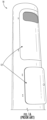
- FIG. 1 A is a photograph of a prior art monopole with two access doors.
- FIG. 1 B is a photograph of a prior art monopole door shown in an open position.
- FIG. 1 C is a photograph of a prior art hinge for the monopole door of FIG. 1 B .
- FIG. 2 is a rear view of a monopole door hinge assembly according to embodiments of the present invention.
- FIG. 3 A is a top view of one of the hinges of FIG. 2 .
- FIG. 3 B is a top view of the hinge of FIG. 3 A mounted to a monopole door.
- FIG. 4 is a rear perspective view of the plurality of hinges of FIG. 2 mounted to a monopole door.
- FIG. 5 is an enlarged bottom perspective view of a hinge base of the hinge of FIG. 3 A .
- FIG. 6 A and FIG. 6 B are photographs showing an example method of installing the hinges to a monopole door according to embodiments of the present invention.
- FIG. 7 is a top perspective view of the hinges of FIG. 2 supporting a monopole door in the open position.
- FIG. 8 is a photograph of the hinges of FIG. 7 supporting a monopole door.
- first, second, etc. may be used herein to describe various elements, components, regions, layers and/or sections, these elements, components, regions, layers and/or sections should not be limited by these terms. These terms are only used to distinguish one element, component, region, layer or section from another region, layer or section. Thus, a first element, component, region, layer or section discussed below could be termed a second element, component, region, layer or section without departing from the teachings of the present invention.
- the sequence of operations (or steps) is not limited to the order presented in the claims or figures unless specifically indicated otherwise.
- phrases such as “between X and Y” and “between about X and Y” should be interpreted to include X and Y.
- phrases such as “between about X and Y” mean “between about X and about Y.”
- phrases such as “from about X to Y” mean “from about X to about Y.”
- a monopole door hinge assembly 100 is illustrated. Similar to the known monopole door assemblies shown in FIGS. 1 A- 1 C , a monopole door hinge assembly 100 of the present invention may comprise a monopole 10 having an interior surface 10 i and an exterior surface 10 e .
- the monopole 10 may comprise one or more doors 12 , each door 12 having a width W, a length L, an interior surface 12 i , and an exterior surface 12 e.
- the monopole door hinge assembly 100 of the present invention may further comprise a plurality of hinges 200 .
- the hinges 200 allow a door 12 to which they are attached to pivot between a closed position and an open position. The ability to pivot helps to provide relatively easy access to the internal components of the monopole 10 by a technician.
- FIG. 3 A is a top view of the hinge 200 by itself and FIG. 3 B is a top view of the hinge 200 secured to a door 12 of a monopole 10 as part of the monopole door hinge assembly 100 .
- each hinge 200 includes a base member 202 and a rib member 204 .
- the base member 202 and the rib member 204 have a length (L BM , L RM ) (see, e.g., FIGS. 2 and 4 ) and a thickness (T BM , T RM ), respectively (see also, e.g., FIGS. 4 and 5 ).
- the thickness of the base member 202 and rib member 204 of each hinge 200 are substantially equal in thickness (T BM , T RM ).
- the thickness (T BM , T RM ) of each hinge 200 is in the range of about 0.125 inches to about 0.375 inches.
- each hinge is 0.25 inches.
- the hinges 200 are made from a material having sufficient strength to support the weight of a monopole door 12 .
- the hinges 200 are formed from steel or a like material.
- the base member 202 provides a point to secure the hinge 200 to the interior surface 10 i of the monopole 10 (see also, e.g., FIG. 5 ) and the rib member 204 provides one or more points to secure the hinge 200 to the door 12 (see, e.g., FIGS. 3 A and 4 ).
- the base member 202 may be configured to be mounted to the interior surface 10 i of the monopole 10 .
- the base member 202 may be mounted to the interior surface 10 i of the monopole 10 via welding.
- the rib member 204 of each hinge 200 includes a supporting portion 204 a and a mounting portion 204 b .
- the supporting portion 204 a of the rim member 204 may have a length L SP that extends a substantial width W of the door 12 .
- the supporting portion 204 a has a length L SP in the range of about 8 inches to about 14 inches.
- the rim member 204 may be mounted to the interior surface 12 i of the door 12 , for example, via welding.
- the supporting portion 204 a of the rim member 204 has an arcuate or curved profile.
- the profile of the supporting portion 204 a of the hinge 200 corresponds to the profile of the interior surface 12 i of the door 12 (see, e.g., FIG. 3 B ).
- Matching the profile of the hinge 200 to correspond with the profile of the door 12 helps to maintain the natural curvature/shape of the door 12 when the hinge 200 is mounted to the door 12 .
- the rib member 204 is typically of sufficient rigidity that it helps to prevent the door 12 from buckling, bending, or otherwise deforming.
- spot welding may be used to help mitigate or eliminate deformation of the curvature/shape of the door 12 during installation of the hinge 200 .
- the mounting portion 204 b of the rib member 204 is substantially C-shaped (see, e.g., FIGS. 2 A- 2 B ). As discussed in further detail below, when the hinge 200 of the present invention is installed on a monopole door 12 , the shape of the mounting portion 204 b allows the door 12 to pivot between the opened and closed position without making contact with the exterior surface 10 e of the monopole 10 (see, e.g., FIGS. 7 and 8 ).
- the supporting portion 204 a of the rib member 204 may comprise one or more protrusions 208 .
- the protrusion(s) 208 extend outwardly from the side of the rib member 204 and are configured to be secured to the interior surface 12 i of the door 12 .
- the protrusions 208 provide multiple points along the rib member 204 to mount (e.g., spot weld points WP) the hinge 200 to the door 12 (see also, e.g., FIG. 6 A- 6 B ). In combination with the accurate profile of the rib member 204 , the protrusions 208 help to maintain the curvature/shape of the door 12 when the hinge 200 is being installed.
- the monopole door hinge assembly 100 of the present invention may comprise two or more hinges 200 .
- the hinges 200 When secured to the interior surface 12 i of the door 12 , the hinges 200 are separated a sufficient distance D apart to support the weight of the door 12 .
- the hinges 200 may be separated a distance D in a range of about 1 inch to about 20 inches or more depending on the size of the door 12 .
- the mounting portion 204 b of the rib member 204 of the hinge 200 is configured to be secured to the base member 202 .
- the rib member 204 is pivotably attached to the base member 202 which allows the door 12 of the monopole 10 to pivot between an opened position and a closed position (see also, e.g., FIG. 7 and FIG. 8 ).
- the mounting portion 204 b and the base member 202 may both comprise an aperture 205 (see, e.g., FIG. 3 A ). Each aperture 205 is substantially the same size and configured to receive a pivot member 210 when aligned.
- the pivot member 210 may comprise a threaded bolt 210 a and nut 210 b .
- the pivot member 210 may further comprise a washer 212 placed between the mounting portion 204 b of the rim member 204 and the base member 202 (see, e.g., FIG. 5 ).
- the washer 212 is formed of a polymeric material.
- the washer 212 may be formed from polycarbonate or like material. Placing the washer 212 between the rim member 204 and the base member 202 of the hinge 200 may help to mitigate or eliminate damage to the outer finish of the monopole 10 (e.g., that may occur when two metallic pieces rub against each other).
- the monopole door hinge assembly 100 of the present invention may comprise the base member 202 of each hinge 200 being mounted (e.g., via welding) to the interior surface 10 i of the monopole 10 , the supporting portion 204 a of each hinge 200 being mounted (e.g., via welding) to the interior surface 12 i of the door 12 , and the mounting portion 204 b of each hinge 200 being pivotably attached (e.g., via bolt and nut) to a respective base member 202 of each hinge 200 , thereby securing the door 12 to the monopole 10 .
- the plurality of hinges 200 is configured to support the weight of the door 12 of a monopole 10 , in particular, when the door 12 is in an opened position.
- the plurality of hinges 200 is configured to support a door 12 of a monopole 10 having a weight in the range of about 1 pound to about 30 pounds or more depending on the size of the door 12 .
- the assembly 100 of the present invention may be configured such that the door 12 will not make contact with the exterior surface 10 e of the monopole 10 when the door 12 swings from an opened position to a close position and vice versa.
- the shape of the mounting portion 204 b of the rim member 204 allows the door 12 to pivot without making contact with the exterior surface 10 e of the monopole 10 , thereby further helping to prevent the door 12 from chipping the outer coating (or finish) of the monopole 10 .
- the shape of the mounting portion 204 b may also allow a side edge of the door 12 to be opened past a longitudinal plane P defined by the door opening 12 o .
- the monopole door hinge assembly 100 of the present invention may allow the door 12 of the monopole 10 to be opened wider than allowed by current hinge assemblies, thereby providing a technician with more room to service the internal components of the monopole 10 .
- the shape of the mounting portion 204 b of the hinges 200 allows for a gap G between the door 12 and the exterior surface 10 e of the monopole 10 .
- the width W G of the gap G is approximately equal to the width W MP of the opening of the mounting portion 204 b .
- the width W G of the gap G between the door 12 and the exterior surface 10 e of the monopole 10 is in the range of about 0.25 inches to about 1 inch.
- the width W G of the gap G between the door 12 and the exterior surface 10 e of the monopole 10 is about 0.5 inches.
- the door 12 may be opened until a section of the mounting portion 204 b adjacent the pivot member 210 makes contact with the interior surface 10 i of the monopole 10 .
- the mounting portion 204 b contacts the interior surface 10 i
- the mounting portion 204 b acts like a lever against the interior surface 10 i of the monopole 10 to help support the weight of the door 12 .
Landscapes
- Engineering & Computer Science (AREA)
- Architecture (AREA)
- Civil Engineering (AREA)
- Structural Engineering (AREA)
- Mechanical Engineering (AREA)
- Life Sciences & Earth Sciences (AREA)
- Chemical & Material Sciences (AREA)
- Materials Engineering (AREA)
- Wood Science & Technology (AREA)
- Hinges (AREA)
Abstract
Description
Claims (16)
Priority Applications (1)
| Application Number | Priority Date | Filing Date | Title |
|---|---|---|---|
| US16/885,974 US11619082B2 (en) | 2019-05-29 | 2020-05-28 | Monopole door hinges and assemblies |
Applications Claiming Priority (2)
| Application Number | Priority Date | Filing Date | Title |
|---|---|---|---|
| US201962853989P | 2019-05-29 | 2019-05-29 | |
| US16/885,974 US11619082B2 (en) | 2019-05-29 | 2020-05-28 | Monopole door hinges and assemblies |
Publications (2)
| Publication Number | Publication Date |
|---|---|
| US20200378164A1 US20200378164A1 (en) | 2020-12-03 |
| US11619082B2 true US11619082B2 (en) | 2023-04-04 |
Family
ID=73549864
Family Applications (1)
| Application Number | Title | Priority Date | Filing Date |
|---|---|---|---|
| US16/885,974 Active 2041-05-28 US11619082B2 (en) | 2019-05-29 | 2020-05-28 | Monopole door hinges and assemblies |
Country Status (1)
| Country | Link |
|---|---|
| US (1) | US11619082B2 (en) |
Cited By (1)
| Publication number | Priority date | Publication date | Assignee | Title |
|---|---|---|---|---|
| US20210315126A1 (en) * | 2020-04-07 | 2021-10-07 | Commscope Technologies Llc | Module for a telecommunications pole |
Families Citing this family (1)
| Publication number | Priority date | Publication date | Assignee | Title |
|---|---|---|---|---|
| WO2021207583A1 (en) | 2020-04-10 | 2021-10-14 | Commscope Technologies Llc | Improved module for a cellular communications monopole |
Citations (58)
| Publication number | Priority date | Publication date | Assignee | Title |
|---|---|---|---|---|
| US1145766A (en) * | 1915-02-03 | 1915-07-06 | Jesse H Hall | Silo-door. |
| US1169669A (en) * | 1915-09-09 | 1916-01-25 | Charles S Mitchell | Hinge for silo-doors. |
| US1265966A (en) * | 1913-05-17 | 1918-05-14 | Canton Culvert & Silo Company | Silo. |
| US1331770A (en) * | 1918-01-05 | 1920-02-24 | Huttig Mill Work Company | Silo-door |
| US3004303A (en) * | 1958-07-04 | 1961-10-17 | Vickers Armstrongs Aircraft | Doors for the fuselages of pressurized aircraft |
| US3550637A (en) * | 1968-06-10 | 1970-12-29 | Pfaff & Kendall | Handhole access assembly |
| US3628216A (en) * | 1970-07-01 | 1971-12-21 | Ford Motor Co | Articulated door hinge |
| US3791073A (en) * | 1972-04-28 | 1974-02-12 | Boeing Co | Aircraft door with moving hinge line |
| US3987596A (en) * | 1975-02-03 | 1976-10-26 | Johann Wolf Gesellschaft M.B.H. Kg | Fodder silo |
| US4271632A (en) * | 1979-12-20 | 1981-06-09 | Vanderloop James P | Silo door |
| US4376360A (en) * | 1981-01-26 | 1983-03-15 | Hanson Silo Company | Access door assembly for a silo |
| US4480408A (en) * | 1983-04-18 | 1984-11-06 | Gerald J. Deuman, Sr. | Self-storing door |
| US4720065A (en) * | 1985-01-24 | 1988-01-19 | The Boeing Company | Translatable outward opening plug-type aircraft door and actuating mechanisms therefor |
| US5180121A (en) * | 1991-05-06 | 1993-01-19 | The Boeing Company | Aircraft door hinge mechanism with selectively triggerable actuator |
| US5305969A (en) * | 1991-07-16 | 1994-04-26 | The Boeing Company | Aircraft door latch lock mechanism |
| US5337977A (en) * | 1993-01-29 | 1994-08-16 | The Boeing Company | Vent-latch interlock assembly for an aircraft door |
| US5455987A (en) * | 1994-04-04 | 1995-10-10 | Svehaug; Oswald C. | One-piece hinge |
| US5483019A (en) * | 1993-09-13 | 1996-01-09 | Angel Guard Products, Inc. | Utility structure having a utility pole and a closure apparatus |
| US5524411A (en) * | 1993-11-24 | 1996-06-11 | Crossman; Robert G. | Handhole cover |
| US5868355A (en) * | 1996-12-09 | 1999-02-09 | Cartercopters, L.L.C. | Fuselage door for pressurized aircraft |
| US20020139897A1 (en) * | 2001-03-30 | 2002-10-03 | Eurocopter Deutschland Gmbh. | Arrangement for moving an airplane door swivellably disposed on a supporting arm |
| US6470645B1 (en) * | 2000-11-09 | 2002-10-29 | Beaird Industries, Inc. | Method for making and erecting a wind tower |
| US20030038500A1 (en) * | 2001-08-22 | 2003-02-27 | Aubry Michael Eugene | Vehicle deck lid power operator |
| US6688806B2 (en) * | 2001-08-21 | 2004-02-10 | Huan-Chang Kuan | Jump-proof manhole-handhole |
| US20060102664A1 (en) * | 2004-11-12 | 2006-05-18 | Gencor Industries Inc. | Apparatus and methods for discharging particulate material from storage silos |
| US20060185874A1 (en) * | 2004-08-26 | 2006-08-24 | Bowman Joseph M | Handhole reinforcing frame for round utility poles |
| US20060279105A1 (en) * | 2005-06-14 | 2006-12-14 | Gm Global Technology Operations, Inc. | Gooseneck Hinge Assembly for Vehicles |
| US20080034675A1 (en) * | 2004-11-10 | 2008-02-14 | Vestas Wind System A/S | Tower Part for a Wind Turbine, an Aperture Cover System, a Method for Manufacturing a Tower Part and Uses Hereof |
| US7774986B2 (en) * | 2004-09-20 | 2010-08-17 | Lisa Dräxlmaier GmbH | Pre-assembly unit for a motor vehicle door |
| US7856759B2 (en) * | 2008-12-18 | 2010-12-28 | Ford Global Technologies, Llc | Dual action power drive unit for a vehicle door |
| US7950719B2 (en) * | 2007-09-14 | 2011-05-31 | Ford Global Technologies, Llc | Vehicle dual hinge rear door articulating and sliding system |
| US20110219711A1 (en) * | 2010-12-16 | 2011-09-15 | General Electric Company | Doorway for a wind turbine tower |
| US20110265402A1 (en) * | 2010-05-03 | 2011-11-03 | Zarges Aluminum Systems Llc | System and Method for Attaching a Door Assembly to a Structure |
| US20120000304A1 (en) * | 2007-08-06 | 2012-01-05 | Hamminga Jeffrey S | Linear drive actuator for a movable vehicle panel |
| US20130219659A1 (en) * | 2010-10-29 | 2013-08-29 | Sugatsune Kogyo Co., Ltd. | Hinge device and base for hinge device |
| US20130234573A1 (en) * | 2012-03-08 | 2013-09-12 | General Electric Company | Appliance with a bracket for supporting a hinge |
| US20140115826A1 (en) * | 2012-10-29 | 2014-05-01 | Hardware Resources, Inc. | Durable low-vibration long arm hinge apparatus |
| US8919698B2 (en) * | 2008-08-04 | 2014-12-30 | The Boeing Company | Translating door centering system |
| US20150052846A1 (en) * | 2013-08-23 | 2015-02-26 | Alstom Renewable Technologies | Tower portion |
| US20150071790A1 (en) * | 2013-09-11 | 2015-03-12 | Ge Wind Energy Gmbh | Articulated slewing jib crane and wind turbine incorporating same |
| US20150089901A1 (en) * | 2012-04-10 | 2015-04-02 | Day Brite Industrial Manufacturing Sdn. Bhd. | Utility pole assembly |
| US20150107179A1 (en) * | 2013-10-18 | 2015-04-23 | Gamesa Innovation & Technology, S.L. | Reinforced hollow for a wind turbine tower |
| US9253556B1 (en) * | 2013-08-29 | 2016-02-02 | ConcealFab Corporation | Dissipative system for increasing audio entropy thereby diminishing auditory perception |
| US9433034B2 (en) * | 2013-08-16 | 2016-08-30 | Commscope Technologies Llc | Modular small cell architecture |
| US9427827B2 (en) * | 2009-05-04 | 2016-08-30 | Pemamek Oy | Method for manufacturing a door frame, welding arrangement and structure of a door frame |
| US9515460B1 (en) * | 2013-05-30 | 2016-12-06 | Cooper Technologies Company | Streetlight base |
| US9630700B2 (en) * | 2014-01-21 | 2017-04-25 | Facc Ag | Device for opening an aircraft door |
| US20170214113A1 (en) * | 2016-01-27 | 2017-07-27 | Sabre Industries Inc. | Radio and power pole |
| US9834979B2 (en) * | 2014-11-24 | 2017-12-05 | Sukup Manufacturing Co. | Arcuate drive through bin door assembly |
| US20180134366A1 (en) * | 2016-11-16 | 2018-05-17 | Airbus Helicopters Deutschland GmbH | Actuatable emergency exit door and an aircraft or space craft with a pressurized cabin having such an actuatable emergency exit door |
| US20180254545A1 (en) * | 2017-03-06 | 2018-09-06 | Commscope Technologies Llc | Modular monopole for wireless communications |
| US20190221913A1 (en) * | 2018-01-16 | 2019-07-18 | Comptek Technologies, Llc | Small modular cell pole |
| US10411336B1 (en) * | 2018-03-05 | 2019-09-10 | CCS Technologies LLC | Pole structure incorporating wireless communications equipment |
| US20200136236A1 (en) * | 2018-10-29 | 2020-04-30 | Commscope Technologies Llc | Perforated door for monopole module and method of mounting same |
| US20200388907A1 (en) * | 2019-06-07 | 2020-12-10 | Commscope Technologies Llc | Small cell antenna assembly and module for same |
| US10947751B2 (en) * | 2018-03-07 | 2021-03-16 | Comptek Technologies, Llc | Utility pole with transparent portion |
| US11067468B2 (en) * | 2018-06-27 | 2021-07-20 | The Boeing Company | Enhanced rig check and leak detection of aircraft doors |
| US20210320393A1 (en) * | 2020-04-10 | 2021-10-14 | Commscope Technologies Llc | Module for a cellular communications monopole |
-
2020
- 2020-05-28 US US16/885,974 patent/US11619082B2/en active Active
Patent Citations (65)
| Publication number | Priority date | Publication date | Assignee | Title |
|---|---|---|---|---|
| US1265966A (en) * | 1913-05-17 | 1918-05-14 | Canton Culvert & Silo Company | Silo. |
| US1145766A (en) * | 1915-02-03 | 1915-07-06 | Jesse H Hall | Silo-door. |
| US1169669A (en) * | 1915-09-09 | 1916-01-25 | Charles S Mitchell | Hinge for silo-doors. |
| US1331770A (en) * | 1918-01-05 | 1920-02-24 | Huttig Mill Work Company | Silo-door |
| US3004303A (en) * | 1958-07-04 | 1961-10-17 | Vickers Armstrongs Aircraft | Doors for the fuselages of pressurized aircraft |
| US3550637A (en) * | 1968-06-10 | 1970-12-29 | Pfaff & Kendall | Handhole access assembly |
| US3628216A (en) * | 1970-07-01 | 1971-12-21 | Ford Motor Co | Articulated door hinge |
| US3791073A (en) * | 1972-04-28 | 1974-02-12 | Boeing Co | Aircraft door with moving hinge line |
| US3987596A (en) * | 1975-02-03 | 1976-10-26 | Johann Wolf Gesellschaft M.B.H. Kg | Fodder silo |
| US4271632A (en) * | 1979-12-20 | 1981-06-09 | Vanderloop James P | Silo door |
| US4376360A (en) * | 1981-01-26 | 1983-03-15 | Hanson Silo Company | Access door assembly for a silo |
| US4480408A (en) * | 1983-04-18 | 1984-11-06 | Gerald J. Deuman, Sr. | Self-storing door |
| US4720065A (en) * | 1985-01-24 | 1988-01-19 | The Boeing Company | Translatable outward opening plug-type aircraft door and actuating mechanisms therefor |
| US5180121A (en) * | 1991-05-06 | 1993-01-19 | The Boeing Company | Aircraft door hinge mechanism with selectively triggerable actuator |
| US5305969A (en) * | 1991-07-16 | 1994-04-26 | The Boeing Company | Aircraft door latch lock mechanism |
| US5337977A (en) * | 1993-01-29 | 1994-08-16 | The Boeing Company | Vent-latch interlock assembly for an aircraft door |
| US5483019A (en) * | 1993-09-13 | 1996-01-09 | Angel Guard Products, Inc. | Utility structure having a utility pole and a closure apparatus |
| US5524411A (en) * | 1993-11-24 | 1996-06-11 | Crossman; Robert G. | Handhole cover |
| US5455987A (en) * | 1994-04-04 | 1995-10-10 | Svehaug; Oswald C. | One-piece hinge |
| US5868355A (en) * | 1996-12-09 | 1999-02-09 | Cartercopters, L.L.C. | Fuselage door for pressurized aircraft |
| US6470645B1 (en) * | 2000-11-09 | 2002-10-29 | Beaird Industries, Inc. | Method for making and erecting a wind tower |
| US20020139897A1 (en) * | 2001-03-30 | 2002-10-03 | Eurocopter Deutschland Gmbh. | Arrangement for moving an airplane door swivellably disposed on a supporting arm |
| US6655634B2 (en) * | 2001-03-30 | 2003-12-02 | Eurocopter Deutschland Gmbh | Arrangement for moving an airplane door swivellably disposed on a supporting arm |
| US6688806B2 (en) * | 2001-08-21 | 2004-02-10 | Huan-Chang Kuan | Jump-proof manhole-handhole |
| US20030038500A1 (en) * | 2001-08-22 | 2003-02-27 | Aubry Michael Eugene | Vehicle deck lid power operator |
| US20060185874A1 (en) * | 2004-08-26 | 2006-08-24 | Bowman Joseph M | Handhole reinforcing frame for round utility poles |
| US7157642B2 (en) * | 2004-08-26 | 2007-01-02 | Hapco Aluminum Pole Products | Handhole reinforcing frame for round utility poles |
| US7774986B2 (en) * | 2004-09-20 | 2010-08-17 | Lisa Dräxlmaier GmbH | Pre-assembly unit for a motor vehicle door |
| US8752337B2 (en) * | 2004-11-10 | 2014-06-17 | Vestas Wind Systems A/S | Tower part for a wind turbine, an aperture cover system, a method for manufacturing a tower part and uses hereof |
| US20080034675A1 (en) * | 2004-11-10 | 2008-02-14 | Vestas Wind System A/S | Tower Part for a Wind Turbine, an Aperture Cover System, a Method for Manufacturing a Tower Part and Uses Hereof |
| US9541059B2 (en) * | 2004-11-10 | 2017-01-10 | Vestas Wind Systems A/S | Tower part for a wind turbine, an aperture cover system, a method for manufacturing a tower part and uses hereof |
| US8109061B2 (en) * | 2004-11-10 | 2012-02-07 | Vestas Wind Systems A/S | Tower part for a wind turbine, an aperture cover system, a method for manufacturing a tower part and uses hereof |
| US20060102664A1 (en) * | 2004-11-12 | 2006-05-18 | Gencor Industries Inc. | Apparatus and methods for discharging particulate material from storage silos |
| US20060279105A1 (en) * | 2005-06-14 | 2006-12-14 | Gm Global Technology Operations, Inc. | Gooseneck Hinge Assembly for Vehicles |
| US20120000304A1 (en) * | 2007-08-06 | 2012-01-05 | Hamminga Jeffrey S | Linear drive actuator for a movable vehicle panel |
| US7950719B2 (en) * | 2007-09-14 | 2011-05-31 | Ford Global Technologies, Llc | Vehicle dual hinge rear door articulating and sliding system |
| US8919698B2 (en) * | 2008-08-04 | 2014-12-30 | The Boeing Company | Translating door centering system |
| US7856759B2 (en) * | 2008-12-18 | 2010-12-28 | Ford Global Technologies, Llc | Dual action power drive unit for a vehicle door |
| US9427827B2 (en) * | 2009-05-04 | 2016-08-30 | Pemamek Oy | Method for manufacturing a door frame, welding arrangement and structure of a door frame |
| US20110265402A1 (en) * | 2010-05-03 | 2011-11-03 | Zarges Aluminum Systems Llc | System and Method for Attaching a Door Assembly to a Structure |
| US20130219659A1 (en) * | 2010-10-29 | 2013-08-29 | Sugatsune Kogyo Co., Ltd. | Hinge device and base for hinge device |
| US8171674B2 (en) * | 2010-12-16 | 2012-05-08 | General Electric Company | Doorway for a wind turbine tower |
| US20110219711A1 (en) * | 2010-12-16 | 2011-09-15 | General Electric Company | Doorway for a wind turbine tower |
| US20130234573A1 (en) * | 2012-03-08 | 2013-09-12 | General Electric Company | Appliance with a bracket for supporting a hinge |
| US20150089901A1 (en) * | 2012-04-10 | 2015-04-02 | Day Brite Industrial Manufacturing Sdn. Bhd. | Utility pole assembly |
| US20140115826A1 (en) * | 2012-10-29 | 2014-05-01 | Hardware Resources, Inc. | Durable low-vibration long arm hinge apparatus |
| US9515460B1 (en) * | 2013-05-30 | 2016-12-06 | Cooper Technologies Company | Streetlight base |
| US9433034B2 (en) * | 2013-08-16 | 2016-08-30 | Commscope Technologies Llc | Modular small cell architecture |
| US20150052846A1 (en) * | 2013-08-23 | 2015-02-26 | Alstom Renewable Technologies | Tower portion |
| US9253556B1 (en) * | 2013-08-29 | 2016-02-02 | ConcealFab Corporation | Dissipative system for increasing audio entropy thereby diminishing auditory perception |
| US20150071790A1 (en) * | 2013-09-11 | 2015-03-12 | Ge Wind Energy Gmbh | Articulated slewing jib crane and wind turbine incorporating same |
| US9279266B2 (en) * | 2013-10-18 | 2016-03-08 | Gamesa Innovation & Technology, S. L. | Reinforced hollow for a wind turbine tower |
| US20150107179A1 (en) * | 2013-10-18 | 2015-04-23 | Gamesa Innovation & Technology, S.L. | Reinforced hollow for a wind turbine tower |
| US9630700B2 (en) * | 2014-01-21 | 2017-04-25 | Facc Ag | Device for opening an aircraft door |
| US9834979B2 (en) * | 2014-11-24 | 2017-12-05 | Sukup Manufacturing Co. | Arcuate drive through bin door assembly |
| US20170214113A1 (en) * | 2016-01-27 | 2017-07-27 | Sabre Industries Inc. | Radio and power pole |
| US20180134366A1 (en) * | 2016-11-16 | 2018-05-17 | Airbus Helicopters Deutschland GmbH | Actuatable emergency exit door and an aircraft or space craft with a pressurized cabin having such an actuatable emergency exit door |
| US20180254545A1 (en) * | 2017-03-06 | 2018-09-06 | Commscope Technologies Llc | Modular monopole for wireless communications |
| US20190221913A1 (en) * | 2018-01-16 | 2019-07-18 | Comptek Technologies, Llc | Small modular cell pole |
| US10411336B1 (en) * | 2018-03-05 | 2019-09-10 | CCS Technologies LLC | Pole structure incorporating wireless communications equipment |
| US10947751B2 (en) * | 2018-03-07 | 2021-03-16 | Comptek Technologies, Llc | Utility pole with transparent portion |
| US11067468B2 (en) * | 2018-06-27 | 2021-07-20 | The Boeing Company | Enhanced rig check and leak detection of aircraft doors |
| US20200136236A1 (en) * | 2018-10-29 | 2020-04-30 | Commscope Technologies Llc | Perforated door for monopole module and method of mounting same |
| US20200388907A1 (en) * | 2019-06-07 | 2020-12-10 | Commscope Technologies Llc | Small cell antenna assembly and module for same |
| US20210320393A1 (en) * | 2020-04-10 | 2021-10-14 | Commscope Technologies Llc | Module for a cellular communications monopole |
Cited By (2)
| Publication number | Priority date | Publication date | Assignee | Title |
|---|---|---|---|---|
| US20210315126A1 (en) * | 2020-04-07 | 2021-10-07 | Commscope Technologies Llc | Module for a telecommunications pole |
| US11985789B2 (en) * | 2020-04-07 | 2024-05-14 | Commscope Technologies Llc | Module for a telecommunications pole |
Also Published As
| Publication number | Publication date |
|---|---|
| US20200378164A1 (en) | 2020-12-03 |
Similar Documents
| Publication | Publication Date | Title |
|---|---|---|
| US11619082B2 (en) | Monopole door hinges and assemblies | |
| US20210075083A1 (en) | Antenna mount kits and antenna mount kit assemblies with equal step tilt adjustment and methods of using the same | |
| US9902240B2 (en) | Vehicle door frame structure | |
| US20050173943A1 (en) | Gutter mounted deck lid hinge | |
| US8595901B1 (en) | Hinge assembly with an adjustable pivot | |
| EP2762366A1 (en) | Sliding door wire harness routing structure | |
| US9458653B2 (en) | Check link structure | |
| JP7393134B2 (en) | window stay | |
| CN105365804B (en) | Device and method for influencing the segmentation of pipeline by mobile object | |
| EP3644436A1 (en) | Radome for base station antenna | |
| US6419293B1 (en) | Torsion bar for a door lid | |
| US20070028940A1 (en) | Hair clip provided with a podium | |
| US20210408664A1 (en) | Universal small cell antenna mounts and antenna mount assemblies | |
| US6616204B1 (en) | Adjustable mounting plate | |
| US9575514B2 (en) | Enclosure features of a portable computing device | |
| US20090230713A1 (en) | Link system and method therefor | |
| US20190145229A1 (en) | Method for Installing a Hatch to a Subsea Structure, Hinge and Assembly for Subsea Use | |
| WO2007140605A1 (en) | Snap-in lifter plate | |
| US10836239B2 (en) | Vehicle panels including integrally formed alignment ribs for inhibiting rotation of vehicle components | |
| US5524324A (en) | Door hinge with an integrated locking device | |
| US20100220021A1 (en) | Vehicle antenna assembly | |
| US11985789B2 (en) | Module for a telecommunications pole | |
| CN208873892U (en) | Shield for antenna for base station | |
| EP3121894B1 (en) | Ship with a planar antenna mast | |
| JP2006183278A (en) | Door inclination correcting tool |
Legal Events
| Date | Code | Title | Description |
|---|---|---|---|
| FEPP | Fee payment procedure |
Free format text: ENTITY STATUS SET TO UNDISCOUNTED (ORIGINAL EVENT CODE: BIG.); ENTITY STATUS OF PATENT OWNER: LARGE ENTITY |
|
| STPP | Information on status: patent application and granting procedure in general |
Free format text: APPLICATION DISPATCHED FROM PREEXAM, NOT YET DOCKETED |
|
| AS | Assignment |
Owner name: COMMSCOPE TECHNOLOGIES LLC, NORTH CAROLINA Free format text: ASSIGNMENT OF ASSIGNORS INTEREST;ASSIGNORS:WILLIAMS, RICHARD D.;ROVELL, KEVIN L.;PATEL, JIGNESH;AND OTHERS;SIGNING DATES FROM 20200529 TO 20200713;REEL/FRAME:053459/0030 |
|
| STPP | Information on status: patent application and granting procedure in general |
Free format text: DOCKETED NEW CASE - READY FOR EXAMINATION |
|
| AS | Assignment |
Owner name: JPMORGAN CHASE BANK, N.A., NEW YORK Free format text: ABL SECURITY AGREEMENT;ASSIGNORS:ARRIS ENTERPRISES LLC;COMMSCOPE TECHNOLOGIES LLC;COMMSCOPE, INC. OF NORTH CAROLINA;REEL/FRAME:058843/0712 Effective date: 20211112 Owner name: JPMORGAN CHASE BANK, N.A., NEW YORK Free format text: TERM LOAN SECURITY AGREEMENT;ASSIGNORS:ARRIS ENTERPRISES LLC;COMMSCOPE TECHNOLOGIES LLC;COMMSCOPE, INC. OF NORTH CAROLINA;REEL/FRAME:058875/0449 Effective date: 20211112 |
|
| AS | Assignment |
Owner name: WILMINGTON TRUST, DELAWARE Free format text: SECURITY INTEREST;ASSIGNORS:ARRIS SOLUTIONS, INC.;ARRIS ENTERPRISES LLC;COMMSCOPE TECHNOLOGIES LLC;AND OTHERS;REEL/FRAME:060752/0001 Effective date: 20211115 |
|
| STPP | Information on status: patent application and granting procedure in general |
Free format text: NON FINAL ACTION MAILED |
|
| STPP | Information on status: patent application and granting procedure in general |
Free format text: RESPONSE TO NON-FINAL OFFICE ACTION ENTERED AND FORWARDED TO EXAMINER |
|
| STPP | Information on status: patent application and granting procedure in general |
Free format text: FINAL REJECTION MAILED |
|
| STCF | Information on status: patent grant |
Free format text: PATENTED CASE |