US11603216B2 - Launch and/or recovery for unmanned aircraft and/or other payloads, including via parachute-assist, and associated systems and methods - Google Patents
Launch and/or recovery for unmanned aircraft and/or other payloads, including via parachute-assist, and associated systems and methods Download PDFInfo
- Publication number
- US11603216B2 US11603216B2 US17/445,067 US202117445067A US11603216B2 US 11603216 B2 US11603216 B2 US 11603216B2 US 202117445067 A US202117445067 A US 202117445067A US 11603216 B2 US11603216 B2 US 11603216B2
- Authority
- US
- United States
- Prior art keywords
- line
- parachute
- capture
- uav
- carriage
- Prior art date
- Legal status (The legal status is an assumption and is not a legal conclusion. Google has not performed a legal analysis and makes no representation as to the accuracy of the status listed.)
- Active
Links
- 238000000034 method Methods 0.000 title claims abstract description 34
- 238000011084 recovery Methods 0.000 title abstract description 11
- 238000000605 extraction Methods 0.000 claims description 5
- 230000004044 response Effects 0.000 claims description 4
- 230000003028 elevating effect Effects 0.000 claims 1
- 238000005516 engineering process Methods 0.000 description 43
- 235000015842 Hesperis Nutrition 0.000 description 11
- 235000012633 Iberis amara Nutrition 0.000 description 11
- 230000008901 benefit Effects 0.000 description 6
- 239000003380 propellant Substances 0.000 description 6
- 230000001133 acceleration Effects 0.000 description 4
- 239000003570 air Substances 0.000 description 4
- 239000007789 gas Substances 0.000 description 4
- 238000013459 approach Methods 0.000 description 3
- 239000007788 liquid Substances 0.000 description 3
- 239000000463 material Substances 0.000 description 2
- 230000008569 process Effects 0.000 description 2
- 239000000126 substance Substances 0.000 description 2
- 241000251468 Actinopterygii Species 0.000 description 1
- 230000009471 action Effects 0.000 description 1
- 230000003213 activating effect Effects 0.000 description 1
- 239000012080 ambient air Substances 0.000 description 1
- 230000005540 biological transmission Effects 0.000 description 1
- 230000001413 cellular effect Effects 0.000 description 1
- 238000004891 communication Methods 0.000 description 1
- 238000013016 damping Methods 0.000 description 1
- 239000001307 helium Substances 0.000 description 1
- 229910052734 helium Inorganic materials 0.000 description 1
- SWQJXJOGLNCZEY-UHFFFAOYSA-N helium atom Chemical compound [He] SWQJXJOGLNCZEY-UHFFFAOYSA-N 0.000 description 1
- 230000002452 interceptive effect Effects 0.000 description 1
- 238000004519 manufacturing process Methods 0.000 description 1
- 230000005055 memory storage Effects 0.000 description 1
- 238000012986 modification Methods 0.000 description 1
- 230000004048 modification Effects 0.000 description 1
- 238000012544 monitoring process Methods 0.000 description 1
- 238000012545 processing Methods 0.000 description 1
- 239000004449 solid propellant Substances 0.000 description 1
- 238000012384 transportation and delivery Methods 0.000 description 1
Images


Classifications
-
- B—PERFORMING OPERATIONS; TRANSPORTING
- B64—AIRCRAFT; AVIATION; COSMONAUTICS
- B64C—AEROPLANES; HELICOPTERS
- B64C39/00—Aircraft not otherwise provided for
- B64C39/02—Aircraft not otherwise provided for characterised by special use
- B64C39/024—Aircraft not otherwise provided for characterised by special use of the remote controlled vehicle type, i.e. RPV
-
- B—PERFORMING OPERATIONS; TRANSPORTING
- B64—AIRCRAFT; AVIATION; COSMONAUTICS
- B64D—EQUIPMENT FOR FITTING IN OR TO AIRCRAFT; FLIGHT SUITS; PARACHUTES; ARRANGEMENTS OR MOUNTING OF POWER PLANTS OR PROPULSION TRANSMISSIONS IN AIRCRAFT
- B64D17/00—Parachutes
- B64D17/78—Parachutes in association with other load-retarding apparatus
-
- B—PERFORMING OPERATIONS; TRANSPORTING
- B64—AIRCRAFT; AVIATION; COSMONAUTICS
- B64F—GROUND OR AIRCRAFT-CARRIER-DECK INSTALLATIONS SPECIALLY ADAPTED FOR USE IN CONNECTION WITH AIRCRAFT; DESIGNING, MANUFACTURING, ASSEMBLING, CLEANING, MAINTAINING OR REPAIRING AIRCRAFT, NOT OTHERWISE PROVIDED FOR; HANDLING, TRANSPORTING, TESTING OR INSPECTING AIRCRAFT COMPONENTS, NOT OTHERWISE PROVIDED FOR
- B64F1/00—Ground or aircraft-carrier-deck installations
- B64F1/02—Arresting gear; Liquid barriers
- B64F1/029—Arresting gear; Liquid barriers using a cable or tether
-
- B—PERFORMING OPERATIONS; TRANSPORTING
- B64—AIRCRAFT; AVIATION; COSMONAUTICS
- B64F—GROUND OR AIRCRAFT-CARRIER-DECK INSTALLATIONS SPECIALLY ADAPTED FOR USE IN CONNECTION WITH AIRCRAFT; DESIGNING, MANUFACTURING, ASSEMBLING, CLEANING, MAINTAINING OR REPAIRING AIRCRAFT, NOT OTHERWISE PROVIDED FOR; HANDLING, TRANSPORTING, TESTING OR INSPECTING AIRCRAFT COMPONENTS, NOT OTHERWISE PROVIDED FOR
- B64F1/00—Ground or aircraft-carrier-deck installations
- B64F1/02—Arresting gear; Liquid barriers
- B64F1/0295—Arresting gear; Liquid barriers aerodynamically or aerostatically supported, e.g. parafoil or balloon
-
- B—PERFORMING OPERATIONS; TRANSPORTING
- B64—AIRCRAFT; AVIATION; COSMONAUTICS
- B64F—GROUND OR AIRCRAFT-CARRIER-DECK INSTALLATIONS SPECIALLY ADAPTED FOR USE IN CONNECTION WITH AIRCRAFT; DESIGNING, MANUFACTURING, ASSEMBLING, CLEANING, MAINTAINING OR REPAIRING AIRCRAFT, NOT OTHERWISE PROVIDED FOR; HANDLING, TRANSPORTING, TESTING OR INSPECTING AIRCRAFT COMPONENTS, NOT OTHERWISE PROVIDED FOR
- B64F1/00—Ground or aircraft-carrier-deck installations
- B64F1/04—Launching or towing gear
-
- B64C2201/182—
-
- B64C2201/185—
-
- B—PERFORMING OPERATIONS; TRANSPORTING
- B64—AIRCRAFT; AVIATION; COSMONAUTICS
- B64U—UNMANNED AERIAL VEHICLES [UAV]; EQUIPMENT THEREFOR
- B64U10/00—Type of UAV
- B64U10/10—Rotorcrafts
- B64U10/13—Flying platforms
- B64U10/14—Flying platforms with four distinct rotor axes, e.g. quadcopters
-
- B—PERFORMING OPERATIONS; TRANSPORTING
- B64—AIRCRAFT; AVIATION; COSMONAUTICS
- B64U—UNMANNED AERIAL VEHICLES [UAV]; EQUIPMENT THEREFOR
- B64U70/00—Launching, take-off or landing arrangements
- B64U70/30—Launching, take-off or landing arrangements for capturing UAVs in flight by ground or sea-based arresting gear, e.g. by a cable or a net
-
- B—PERFORMING OPERATIONS; TRANSPORTING
- B64—AIRCRAFT; AVIATION; COSMONAUTICS
- B64U—UNMANNED AERIAL VEHICLES [UAV]; EQUIPMENT THEREFOR
- B64U70/00—Launching, take-off or landing arrangements
- B64U70/80—Vertical take-off or landing, e.g. using rockets
- B64U70/83—Vertical take-off or landing, e.g. using rockets using parachutes, balloons or the like
Definitions
- the present technology is directed generally to launch and/or recovery for unmanned aircraft and/or other payloads, including via parachute assist, and associated systems and methods.
- Unmanned aircraft or aerial vehicles provide enhanced and economical access to areas where manned flight operations are unacceptably costly and/or dangerous.
- unmanned aircraft outfitted with remotely controlled cameras can perform a wide variety of surveillance missions, including spotting schools of fish for the fisheries industry, monitoring weather conditions, providing border patrols for national governments, and providing military surveillance before, during and/or after military operations.
- Existing unmanned aircraft systems suffer from a variety of drawbacks.
- existing unmanned aircraft systems (which can include the aircraft itself along with launch devices, recovery devices, and storage devices) typically require a substantial amount of space. Accordingly, these systems can be difficult to install and operate in cramped quarters, such as the deck of a small fishing boat, land vehicle, or other craft.
- Another drawback with some existing unmanned aircraft is that, due to small size and low weight, they can be subjected to higher acceleration and deceleration forces than larger, manned air vehicles and can accordingly be prone to damage, particularly when manually handled during recovery and launch operations in hostile environments, such as a heaving ship deck.
- FIG. 1 A is a partially schematic illustration of a system that includes a mission aircraft, a lift device, and a line control device configured in accordance with embodiments of the present technology.
- FIG. 1 B is a partially schematic illustration of the system shown in FIG. 1 A with the lift device positioned for an aircraft capture operation in accordance with embodiments of the present technology.
- FIG. 1 C is a partially schematic illustration of the system shown in FIG. 1 A with the mission aircraft captured in accordance with embodiments of the present technology.
- FIG. 1 D is a partially schematic illustration of the system shown in FIG. 1 A with the lift device and mission aircraft landed, in accordance with embodiments of the present technology.
- FIG. 2 A is a partially schematic illustration of a lift device that includes one or more rockets in accordance with embodiments of the present technology.
- FIGS. 2 B and 2 C illustrate lift devices that include a kite ( FIG. 2 B ) and a balloon ( FIG. 2 C ), in accordance with embodiments of the present technology.
- FIG. 3 A is a partially schematic illustration of a system that includes a landing structure configured in accordance with embodiments of the present technology.
- FIG. 3 B is a partially schematic illustration of the system of FIG. 3 A , with a mission aircraft landed on a landing structure in accordance with embodiments of the present technology.
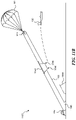
- FIG. 4 A is a partially schematic, isometric illustration of a system that includes a line control device supported by multiple vehicles in accordance with embodiments of the present technology.
- FIGS. 4 B, 4 C, and 4 D illustrate representative carriage tracks for use with the system shown in FIG. 4 A , in accordance with embodiments of the present technology.
- FIG. 5 A is partially schematic illustration of a launcher that includes a rocket, in accordance with embodiments of the present technology.
- FIG. 5 B is a partially schematic illustration of the system shown in FIG. 5 A , with the aircraft released by the rocket in accordance with embodiments of the present technology.
- FIG. 5 C is a partially schematic illustration of a process for retrieving the rocket shown in FIGS. 5 A and 5 B , in accordance with embodiments of the present technology.
- FIG. 5 D is a partially schematic illustration of a system that includes multiple rockets for launching an aircraft, in accordance with embodiments of the present technology.
- FIG. 6 is a partially schematic illustration of a launcher having a carriage track and carriage propelled in accordance with embodiments of the present technology.
- FIGS. 7 A- 7 D illustrate representative techniques for carrying an aircraft with a carriage in accordance with embodiments of the present technology.
- FIG. 8 is a partially schematic illustration of a launcher having a carriage track supported by multiple vehicles in accordance with embodiments of the present technology.
- FIGS. 9 A- 9 C illustrate a representative system configured to both launch and recover an aircraft, using a parachute, in accordance with embodiments of the present technology.
- FIGS. 10 A- 10 C illustrate another representative system for launching an aircraft using a parachute, in accordance with embodiments of the present technology.
- FIGS. 11 A- 11 B illustrate still another representative system for launching an aircraft using a parachute, in accordance with embodiments of the present technology.
- FIGS. 12 A- 12 C illustrate a system for lofting a person or other payload over an obstruction, in accordance with embodiments of the present technology.
- FIGS. 13 A- 13 C illustrate further details of a carriage configured to loft a person or other payload, in accordance with embodiments of the present technology.
- the present disclosure describes systems and methods for launching and/or recovering aircraft, in particular, unmanned aircraft.
- Many specific details of some embodiments of the disclosure are set forth in the following description and FIGS. 1 - 13 C to provide a thorough understanding of these embodiments.
- Well-known structures, systems, and methods that are often associated with such embodiments, but that may unnecessarily obscure some significant aspects of the disclosure, are not set forth in the following description for purposes of clarity.
- some embodiments of the technology can have different configurations and/or different components than those described in this section. As such, the technology may include embodiments with additional elements, and/or without several of the elements described below with reference to FIGS. 1 - 13 C .
- the relative scales of the system components described herein may be exaggerated.
- the relative sizes of multiple UAVs used in a single system e.g., one UAV to loft and/or capture another to carry out a mission
- the relative sizes of multiple UAVs used in a single system may be different than what is shown in the Figures.
- computer- or controller-executable instructions may take the form of computer- or controller-executable instructions, including routines executed by a programmable computer or controller.
- the technology can be embodied in a special-purpose computer, controller or data processor that is specifically programmed, configured or constructed to perform one or more of the computer-executable instructions described below.
- the terms “computer” and “controller” as generally used herein refer to any data processor and can include Internet appliances and hand-held devices (including palm-top computers, wearable computers, cellular or mobile phones, multi-processor systems, processor-based or programmable consumer electronics, network computers, mini computers and the like). Information handled by these computers can be presented at any suitable display medium, including an LCD.
- the technology can also be practiced in distributed environments, where tasks or modules are performed by remote processing devices that are linked through a communications network.
- program modules or subroutines may be located in local and remote memory storage devices.
- aspects of the technology described below may be stored or distributed on computer-readable media, including magnetic or optically readable or removable computer disks, as well as distributed electronically over networks. Data structures and transmissions of data particular to aspects of the technology are also encompassed within the scope of embodiments of the technology.
- FIG. 1 A is a partially schematic illustration of a system 100 that includes a first or mission aircraft 120 , a lift device 110 , and a line control device 130 .
- the mission aircraft 120 is typically an unmanned aerial vehicle that flies a reconnaissance, surveillance, and/or other mission under remote control, and/or autonomously.
- the lift device 110 carries a capture line 116 aloft toward the end of the mission. The mission aircraft 120 then engages the capture line 116 , and the line control device 130 guides the captured mission aircraft to a safe landing.
- the lift device 110 can also include an aircraft, for example, a second aircraft 111 that carries a parachute 161 .
- the parachute 161 can be used to control the motion of the capture line 116 , as will be described in further detail below.
- the first or mission aircraft 120 can include a fuselage 121 , wings 122 , and a propulsion system 124 that further includes one or more propellers 125 (e.g., a single propeller arranged in a pusher configuration).
- the mission aircraft 120 can include one or more first capture devices 123 , for example, hooks or cleats at the ends of the wings 122 that are used to engage with the capture line 116 . Accordingly, capture line 116 represents an example of a second capture device 115 .
- the capture line 116 is attached to the parachute 161 , which can be stowed in a canister or other receptacle 160 carried by the lift device 110 .
- the lift device 110 can further include an airframe 112 , rotors 113 , and landing gear 114 .
- the landing gear 114 are positioned and sized to allow the lift device 110 to land with the canister 160 attached.
- the capture line 116 is also attached to the line control device 130 .
- the line control device 130 can include a boom 131 having a line support element 135 (e.g., a hook, pulley, or other suitable device) through or around which the capture line 116 passes.
- the capture line 116 can be connected to a tension device 134 (e.g., a winch or other device that applies tension to, reels in, and/or otherwise applies forces to the capture line 116 ). Accordingly, the tension device 134 provides tension on the capture line 116 and/or can winch or reel in the capture line 116 to bring the captured mission aircraft 120 to a safe landing.
- the boom 131 can extend upwardly at an angle and can be supported by boom supports 132 .
- the line control device 130 can be modular and can be broken down to fit into one or more shipping containers 133 . Further details are described in U.S. Pat. No. 10,836,509, incorporated herein by reference.
- the overall system 100 can include a control system 101 , which in turn can include one or more controllers 102 , four of which are shown in FIG. 1 A as first-fourth controllers 102 a - 102 d .
- the control system 101 can be used to control the operations of the line control device 130 , the mission aircraft 120 , and the lifting device 110 , independently, or via a centralized controller 102 a . Accordingly, any of the operational steps described herein can be conducted by, authorized by, initiated, and/or carried out via computer-executable instructions carried on any one or more of the components of the control system 101 .
- the control system 101 can receive any of a variety of suitable inputs, e.g., from sensors and/or human operators, and issue corresponding instructions. Representative inputs include, among others, velocity, altitude, pressure, tension, force, and/or winch rotation speeds.
- FIG. 1 B illustrates the system 100 with the lift device 110 aloft, and with the capture line 116 positioned generally to intersect a flight path 126 of the mission aircraft 120 .
- the mission aircraft 120 can be captured in accordance with one or more of a variety of suitable techniques.
- the mission aircraft 120 engages the first capture device 123 carried at one of the wingtips 122 , with the second capture device 106 (e.g., the capture line 116 ) while the parachute 161 is carried in the canister 160 .
- the tensile force placed on the parachute 161 by the mission aircraft 120 as it engages with the capture line 116 pulls the parachute 161 out of the canister 160 , so that the parachute 161 unfurls.
- the tension device 134 reels in the capture line 116 after (and, optionally, before) the mission aircraft 120 engages the capture line 116 to provide/maintain tension on the capture line 116 as the parachute 161 descends.
- the descent of the captured mission aircraft 120 is slowed by the deployed parachute 161 , as will be described further with reference to FIG. 1 C .
- the parachute 161 can be deployed by directing the lift device 110 upwardly while the capture line 116 is prevented from unspooling any further from the tension device 134 . Accordingly, the upward trajectory of the lift device 110 pulls the canister 160 away from the parachute 161 , e.g., before the mission aircraft 120 strikes the capture line 116 .
- the tension device 134 rapidly reels in the capture line 116 to pull the parachute 161 from the canister 160 .
- the action of deploying the parachute 161 from the canister 160 can be expedited and/or made more reliable via an extraction device 162 carried in or proximate to the canister 160 .
- the extraction device 162 can include a spring-powered piston that propels the parachute 161 from the canister 160 , in response to an actuator signal delivered by an operator, or (automatically) in response to an increase in tension on the capture line 116 .
- FIG. 1 C illustrates the system 100 after the parachute 161 has been deployed from the canister 160 .
- the lift device 110 stays in place or moves away from the parachute 161 (e.g., above the parachute 161 ) to avoid interfering with the process for capturing the mission aircraft 120 .
- the parachute 161 can include stays or struts 164 that aid in opening the parachute 161 and/or keeping the parachute 161 open, and that can be actuated via expansion devices 163 (e.g., springs or other suitable devices) to increase the speed with which the parachute 161 deploys.
- expansion devices 163 e.g., springs or other suitable devices
- the tension device 134 continues to reel in the capture line 116 , against the drag force provided by the parachute 161 . Accordingly, the mission aircraft 120 descends in a relatively slow, controlled manner.
- FIG. 1 D illustrates the system 100 after the mission aircraft 120 has been brought to rest at the line control device 130 .
- the parachute 161 collapses and comes to rest on the ground (or other surface, e.g., a ship deck), or hangs suspended from the line support element 135 .
- the lift device 110 also returns to the ground (or other surface), landing with the canister 160 intact and ready to be reloaded with the parachute 161 for the next operation.
- the second aircraft 111 described above with reference to FIGS. 1 A- 1 D represents one type of lift device that can be used to elevate and deploy the parachute 161 used to support the capture line 116 .
- the system can include lift devices having other configurations.
- FIG. 2 A illustrates a lift device 210 a that includes one or more rockets 270 attached to the canister 160 in which the parachute 161 is positioned.
- the rockets 270 can include relatively small, solid propellant rockets that elevate the canister 160 to a suitable altitude at which the parachute 161 deploys.
- the parachute 161 can deploy when the altitude of the lift device 201 a exceeds the length of the deployed capture line 116 , with or without assistance from the extraction device 162 , and/or by reeling in the tension device 134 , as discussed above.
- the elapsed time between launching the rocket or rockets 270 and deploying the parachute 161 is relatively short. Accordingly, the rockets 270 will be launched shortly before the mission aircraft 120 ( FIG. 1 A ) is at the end of its mission. This is unlike the second aircraft 111 described above with reference to FIGS. 1 A- 1 D , which can loiter for some period of time before deploying the parachute it carries.
- the lift device can have other configurations.
- FIG. 2 B illustrates a lift device 210 b having the form of a kite 271 that carries the canister 160 , parachute 161 , and capture line 116 aloft.
- the kite 271 can have a parasail-type configuration, or another suitable configuration, and the associated parachute 161 can be deployed in accordance with any of the methods described above.
- FIG. 2 C illustrates a lift device 210 c that includes a balloon 272 filled with helium or another lighter-than-ambient-air gas (e.g., hot air).
- the balloon 272 can be positioned aloft and can remain on station for a period of time before the parachute 161 is deployed from the canister 160 , using any of the techniques described above.
- FIG. 3 A illustrates a system 300 having several elements similar to corresponding elements described above, as well as a line control device 330 that includes a landing structure 336 .
- the landing structure 336 can include an inflatable or otherwise collapsible device 337 , e.g., having a generally cone-shaped outer surface.
- the exterior of the landing structure 336 can be formed from a heavy-duty plastic or other suitable material that is airtight, compliant, and resilient, so as to cushion the impact with the mission aircraft 120 , without being punctured by the impact.
- the capture line 116 can pass through first and second apertures 338 a , 338 b in the landing structure 336 to connect to the tension device 134 .
- the parachute 161 can be deployed from the canister 160 carried by the lift device 110 , in accordance with any techniques described above.
- the tension device 134 has drawn the capture line 116 downwardly until the mission aircraft 120 has engaged the landing structure 336 .
- the flexible, resilient characteristics of the landing structure 336 pad the impact of the mission aircraft 120 , and the conical shape can act to spread the impact forces.
- FIG. 4 A is a partially schematic illustration of a system 400 that may not include a parachute-assist for recovering the mission aircraft 120 .
- the system 400 can include a line control device 430 that in turn includes a carriage 450 to which the capture line 116 is attached.
- the carriage 450 travels along a carriage track 445 after the mission aircraft 120 has engaged the capture line 116 .
- the carriage track 445 can include a flexible line 442 that is held in position by one or more supports 432 , e.g., two supports, shown as a first support 432 a and a second support 432 b .
- Each support 432 can include an upright portion 443 , and one or more boom portions 431 , illustrated as an upper boom portion 431 a and a lower boom portion 431 b .
- the upper boom portions 431 a can be supported relative to the upright portion 443 with a guyline 441
- each upright portion 443 can be supported by a corresponding vehicle 439 a , 439 b .
- each upright portion 443 can be supported relative to the corresponding vehicle 439 a , 439 b with one or more braces 440 providing for additional support.
- the vehicles 439 a , 439 b can include pickup trucks or other suitable utility vehicles in which the components of the system 400 can be stowed when not in use.
- the carriage 450 can be coupled to the capture line 116 via a restraint device 451 that can in turn include a restraint line 452 , and one or more tension devices 434 .
- a restraint device 451 that can in turn include a restraint line 452 , and one or more tension devices 434 .
- the capture line 116 can pass over a series of pulleys 444 , which are connected to the tension devices 434 .
- the tension devices 434 provide a braking force on the capture line 116 , the carriage 450 , and the mission aircraft 120 until the mission aircraft 120 comes to rest, hanging from the capture line 116 .
- a brake or other device can secure the carriage 450 in position toward the end of the carriage track 445 until the tension in the tension device 434 is controllably released and the mission aircraft 120 is removed.
- the carriage track 445 includes a flexible line 442 .
- FIG. 4 B illustrates the flexible line 442 rolled up on a reel 446 . Accordingly, the flexible line 442 can be easily stowed when not in use.
- the carriage track 445 can have a rigid but collapsible configuration.
- the carriage track 445 can be made from telescoping sections 447 c
- the carriage track 445 can be made from folding sections 447 d .
- the system can be rapidly erected and taken down, and can be rapidly moved from one location to another via the vehicles 439 a , 439 b.
- FIGS. 5 A- 5 D schematically illustrate a system 500 that includes a launcher 580 and a parachute that is used to land an element of the launcher 580 rather than landing the mission aircraft 120 .
- the launcher 580 can include a rocket 581 having a carriage 550 that releasably supports the mission aircraft 120 .
- the launcher 580 can further include a launch guide 582 that extends upwardly and engages with corresponding guide elements 583 carried by the rocket 581 . During launch, the guide elements 583 slide along the launch guide 582 to properly orient the rocket 581 during launch.
- the rocket 581 has been launched, and the mission aircraft 120 has been released from the carriage 550 .
- the mission aircraft 120 can be released from the carriage 550 at the apogee of the rocket trajectory, and can then perform a dive and recovery maneuver to gain sufficient airspeed to perform its mission.
- the rocket 581 has deployed a parachute 561 so as to be reused for another mission.
- the mission aircraft 120 has attained level flight and has begun its mission.
- FIG. 5 D illustrates an embodiment in which the launcher 580 includes two rockets 581 , shown as a first rocket 581 a and a second rocket 581 b , each of which includes guide elements 583 engaged with corresponding launch guides 582 a , 582 b and corresponding portions of a centrally-positioned carriage 550 d .
- the multi-rocket configuration can provide increased stability and control when launching the mission aircraft 120 .
- the system 500 can include two rockets, and in other embodiments, the system can include other numbers of rockets, for example, three rockets arranged in the manner generally described above with reference to FIG. 2 A .
- FIGS. 6 - 8 illustrate further representative systems for launching the mission aircraft 120 , in accordance with embodiments of the present technology.
- FIG. 6 illustrates a launcher 680 that includes a carriage track 684 carried between first and second supports 685 a , 685 b .
- a corresponding carriage 650 carries the mission aircraft 120 and is coupled to a carriage driver 686 .
- the carriage driver 686 propels the carriage 650 along the carriage track 684 .
- the carriage 650 rapidly decelerates at the end of the carriage track 684 , and the mission aircraft 120 is released from the carriage 650 for flight.
- the carriage driver 686 can propel the carriage 650 along the carriage track 684 using any of a variety of suitable techniques.
- the carriage driver 686 can be filled with compressed gas or liquid, which is directed aft to accelerate the carriage 650 in a forward direction.
- the carriage driver 686 can be made smaller by supplying it with additional propellant from a fixed, ground-based propellant source 687 coupled to the carriage driver 686 with a propellant supply line 688 .
- the propellant source 687 and supply line 688 can supply the carriage driver 686 with enough compressed gas and/or liquid to accelerate the carriage 650 to the target lift-off speed (of the mission aircraft 120 ) at the end of the carriage track 684 .
- the carriage driver 686 can include a chemical propellant, for example, a rocket engine that propels the carriage 650 along the carriage track 684 .
- the carriage driver 686 can be propelled using a mechanical device, for example, a spring or bungee, that can be connected to the first support 685 a , and that can take the place of the propellant supply line 688 to accelerate the carriage 650 along the carriage track 684 .
- the carriage 650 supports the mission aircraft 120 during its acceleration, and is positioned and configured to release the mission aircraft at the end of its acceleration run.
- FIGS. 7 A- 7 D are partially schematic illustrations of representative carriages configured to carry out this operation.
- a representative carriage 750 a includes multiple upwardly extending engagement portions 753 a that engage with the trailing edge of the mission aircraft wings 122 .
- the engagement portions 753 a are spaced apart by a distance at least as great as the diameter of the propeller 125 so that, upon release, the propeller 125 passes between the engagement portions 753 a as the mission aircraft 120 is released for flight.
- FIGS. 7 B and 7 C illustrate a portion of another carriage 750 b configured to engage with the fuselage 121 of the mission aircraft 120 .
- the fuselage 121 can include fuselage engagement portions 727 that extend outwardly from the main outer mold line of the fuselage 121 .
- the carriage 750 b can include corresponding carriage engagement portions 753 b that engage with the rearward facing surfaces of the fuselage engagement portions 727 . Accordingly, the carriage 750 b pushes on the fuselage 121 to accelerate it, and allows the mission aircraft 120 to release in a forward direction for flight.
- the carriage engagement portions 753 b fold down (e.g., in a forward direction) as the mission aircraft is released, so as not to interfere with the propeller 125 as it passes by.
- FIG. 7 D illustrates another representative carriage 750 d configured to engage with the propeller 125 of the mission aircraft 120 .
- the propeller 125 is attached to a hub 729 that is rotated relative to the fuselage 121 via a drive shaft 719 .
- a rearward facing spinner 728 projects rearwardly from the propeller 125 and can be releasably engaged with a carriage engagement portion 753 d supported in position by the carriage 750 d .
- An intermediate bearing 754 allows the carriage engagement portion 753 d to rotate with the propeller 125 relative to the carriage 750 d during the carriage acceleration run.
- Additional supports 755 engage the wings 122 of the mission aircraft 120 to support its weight.
- the supports 755 are located far enough outboard along the wings 122 so as not to interfere with the propeller 125 as it passes by.
- the mission aircraft 120 continues to travel forwardly, with the spinner 728 disengaging from the carriage engagement portion 753 d , and with the wings 122 lifting off the supports 755 .
- FIG. 8 illustrates another representative system 800 that includes a launcher 880 supported by two vehicles 839 , shown as a first vehicle 839 a , and a second vehicle 839 b .
- Each vehicle can carry a corresponding support, shown as a first support 885 a and a second support 885 b .
- a carriage track 884 is carried between the first and second supports 885 a , 885 b .
- the carriage track 884 can include a pair of flexible lines, each generally similar to the line discussed above with reference to FIGS. 4 A and 4 B , or a rigid, but collapsible, structure, as described above with reference to FIGS. 4 C and 4 D .
- a corresponding carriage 850 shown schematically in FIG.
- the carriage track 884 can remain in tension as a result of the weights of the respective vehicles 839 a , 839 b , with the supports held in position via corresponding braces 889 .
- the first and/or the second vehicle 839 a , 839 b can be placed in “drive” so as to increase the tension on the carriage track 884 .
- a block and tackle, or other suitable device can be used to provide a mechanical advantage for accelerating the carriage 850 , and/or the tension device 834 can include a spring, bungee, and/or other suitable device, in addition to or in lieu of a winch.
- FIG. 9 A illustrates a system 900 that includes common elements suitable for both launching and capturing the mission aircraft 120 , in accordance with embodiments of the present technology.
- the system 900 can include a lift line/capture line 992 that can operate to lift the mission aircraft 120 and, optionally, capture the mission aircraft 120 .
- the line 992 is initially attached to the mission aircraft 120 via an attachment/release device 994 , and passes over pulleys 944 carried by a pulley support 991 .
- the two pulleys 944 are spaced apart from each other so as to avoid contact between the portions of the line 992 passing over each pulley.
- the system can include a spreader 993 connected between the attachment/release device 994 and a slide guide 995 (e.g., an open-ended cylinder through which the line 992 passes).
- a spreader 993 connected between the attachment/release device 994 and a slide guide 995 (e.g., an open-ended cylinder through which the line 992 passes).
- the spreader 993 , the attachment/release device 994 , and the slide guide 995 form a unitary structure.
- the line 992 is attached to a tension device 934 (e.g., a winch).
- the lift device 110 lifts the pulley support 991 while the mission aircraft 120 remains in a generally fixed position on or near the ground.
- the tension device 934 unspools the line 992 , allowing the lift device 110 to gain altitude, while the slide guide 995 allows the unwinding line 992 to pass upwardly around the pulleys 944 .
- the parachute 161 is deployed from the cannister 160 , for example, using any of the techniques described above.
- the pulley support 991 begins to descend, under the braking force supplied by the parachute 161 , as indicated by arrow D.
- the tension device 934 is activated, to rapidly draw in the line 992 , as indicated by arrow B.
- the rate at which line 992 is drawn in is greater than the rate at which the pulley support 991 descends.
- the mission aircraft 120 begins to ascend, as indicated by arrow C.
- the tension device 934 can reel in the lift line/capture line 992 at a rate two or three times greater than the descent rate of the pulley support 991 , causing the mission aircraft 120 to gain sufficient altitude for launch. Accordingly, the parachute 161 is deployed at an altitude significantly greater than the altitude at which the mission aircraft 120 is to be released. For example, if the mission aircraft 120 is to be released at an altitude of 200 feet, and the tension device 934 draws in the line 992 at three times the rate of descent of the pulley support 991 , then the parachute 161 is deployed at an altitude of at least 600 feet.
- altitudes and winch-in rates can be used, depending on factors that include the target release altitude for the mission aircraft 120 , the weight of the pulley support 991 and associated line 992 , and the braking force applied by the parachute 161 .
- the parachute 161 and pulley support 991 have descended from the lift device 110 , and the mission aircraft 120 has been elevated as a result of the differential between the rate at which the line 992 is taken up by the tension device 934 , and the descent rate of the parachute 161 .
- the mission aircraft 120 can be released from the attachment/release device 994 .
- the mission aircraft 120 then dives, recovers, and flies its mission, as indicated by arrow E.
- the pulley support 991 continues its descent under the braking force of the parachute 161 , and the tension device 934 can simply reel in the resulting slack, or can actively pull on the pulley support 991 and the parachute 161 to increase the descent rate.
- the pulley support 991 , the spreader 993 , and the slide guide 995 can be removed, and the attachment/release device 994 can be attached directly to the parachute 161 , which is re-packaged into the canister 160 .
- the lift device 110 lifts the line 992 , which is now used as a capture line.
- the capture operation is then conducted in a manner generally similar to that described above with reference to FIGS. 1 A- 3 B , using any of the ground-based line control devices or recovery devices described above. If the spreader 993 , the slide guide 995 and the attach/release device 994 are manufactured as a unitary element, the entire element can be removed, and the line 992 can be attached to the parachute 161 via a separate attachment device.
- the same line 992 can be used for both launch and capture.
- a different line can be used for each operation, with the lines being swapped out while the mission aircraft 120 conducts its mission.
- the two lines can be the same (e.g., for enhanced commonality) or different (e.g., if the loads and/or other requirements for the line differ significantly between launch and capture).
- the hardware attached to the line 992 is changed between the launch and recovery operations.
- the operator uses different sets of hardware, one for launch and one for capture, but uses the same lift device 110 for both operations.
- the operator can also use the same tension device 934 in some embodiments, or a different tension device in other embodiments. Accordingly, the degree to which elements are used for both launch and capture can be selected depending on factors that may include the characteristics of the mission aircraft 120 , the lift device 110 , the line 992 and/or the tension device 934 .
- FIGS. 10 A- 10 B are schematic illustrations of systems that include a ground- or ship-based launcher, with a parachute assist.
- the system can include a launcher 1080 that releasably supports the mission aircraft 120 .
- the mission aircraft 120 is coupled to a line 992 via a releasable attachment device 1094 .
- the line 992 is wrapped around a pulley 944 and connected to a tension device 934 toward one end, and to a parachute 161 toward the other end.
- the parachute 161 is initially packed inside the canister 160 carried by the lifting device 110 .
- the lifting device 110 carries the parachute 161 , the pulley 944 and the line 992 to a target altitude, at which the parachute 161 is then deployed.
- the lifting device 110 can remain above the parachute 161 so as not to interfere with the launch operation.
- the tension device 934 rapidly draws in the line 992 at a rate significantly faster than the rate at which the pulley 944 and parachute 161 descend.
- the mission aircraft 120 accelerates off the launcher 1080 and into the air.
- the mission aircraft 120 has achieved suitable velocity for flight, and can be released by disengaging the releasable attachment device 1094 .
- the mission aircraft 120 is shown in FIG.
- the line 992 can be sufficiently long that the mission aircraft 120 achieves a velocity suitable for flight well before it approaches the parachute 161 , thus reducing or eliminating the likelihood for contact between the mission aircraft 120 and the parachute 120 .
- the relative sizes of the system components may be different than those shown in the Figures.
- the lifting device 110 may be significantly smaller than the mission aircraft 120 , and/or the parachute 161 .
- the lifting device 110 can include a quadcopter having a two-foot diameter, while the parachute 161 (when deployed) can have a twenty-foot diameter.
- FIG. 10 C illustrates another representative arrangement in which the system includes a tension device 934 that is spaced further apart from the launcher 1080 than is shown in FIGS. 10 A and 10 B .
- the operation of the system shown in FIG. 10 C is similar to that described above with reference to FIGS. 10 A and 10 B ; however, the load applied to the parachute 161 is expected to be reduced as a result of the increased spacing.
- the aircraft can be released for its mission well before reaching the parachute 161 and the pulley 944 , so as to avoid these elements (e.g., by flying under or around these elements).
- FIGS. 11 A- 11 B illustrate another arrangement for lofting (e.g., launching) an aircraft, using a parachute, in which the aircraft passes beneath the parachute, rather than over the parachute, as shown in FIG. 10 B . It is expected that in at least some embodiments, launching the aircraft to pass beneath the parachute will reduce the likelihood for interference between the aircraft and the parachute.
- a representative system 1100 can include a launcher 1080 from which the mission aircraft 120 is launched, and a carriage 1150 supported from and moveable along the line 992 .
- the carriage 1150 can releasably carry the mission aircraft 120 via one or more releasable attachment devices 1194 .
- two releasable attachment devices 1194 have gripper-type configurations.
- a release line 1195 is attached to the carriage 1150 , and is coupled to a release line actuator 1196 .
- the lifting device 110 carries the parachute 161 in the canister 160 , with the parachute attached to the pulley 944 , around which the line 992 is positioned.
- the tension device 934 rapidly reels in the line 992 , which pulls the carriage 1150 and the mission aircraft 120 off the launcher 1080 .
- the line 992 passes through apertures 1151 in the carriage 1150 so that the carriage 1150 can move upwardly along the line 992 as it carries the mission aircraft 120 aloft.
- the mission aircraft 120 is released from the carriage 1150 via the releasable attachment devices 1194 .
- the release line actuator 1196 is activated, e.g., to brake the release line 1195
- the releasable attachment devices 1194 release the mission aircraft 120 .
- the released mission aircraft 120 flies off, as indicated in FIG. 11 B .
- the release line actuator 1196 can include one or more damping devices to reduce the impact on the overall system 1100 as the carriage 1150 is halted.
- the parachute 161 can gently guide the carriage 1150 and pulley 944 to the ground, after which the system 1100 can be reloaded for the next aircraft launch.
- FIG. 12 A illustrates a representative system 1200 that includes a line 992 coupled to a tension device 934 and carried aloft via a lifting device 110 , generally in the manner described above.
- the lifting device 110 releases a parachute 161 and pulley 944 from a corresponding canister 160 , also in a manner generally similar to that described above.
- the line 992 is attached to a carriage 1250 , extends around the pulley 944 , passes through apertures 1251 in the carriage 1250 , and is attached to the tension device 934 .
- a person 1253 is connected to the carriage 1250 via a harness 1252 .
- the line 992 is attached to the carriage 1250 via a releasable attachment device 1294 .
- the system 1200 can be deployed to hoist the person 1253 up and over an obstruction 1202 for a parachute-controlled landing at a landing zone 1201 on the opposite side.
- the obstruction 1202 can have a width W (e.g., 20 feet) and a height H (e.g., 50 feet).
- the length of the line 992 , the altitude at which the parachute 161 is released (e.g., 500 feet above ground level, in some embodiments), and/or other factors, can be selected to account for obstructions 1202 having different widths W and/or heights H.
- FIG. 12 B the person 1253 has been lofted via the carriage 1250 to a position above and beyond the obstruction 1202 .
- the parachute 161 is then used to gently guide the person 1253 to the landing zone 1201 .
- the tension device 934 can reel in the line 992 until the carriage 1250 engages with the pulley 944 .
- the line 992 can be released, and the person 1253 (hanging from the parachute 161 via the harness 1252 , the carriage 1250 , the pulley 944 , and a parachute connector 1262 ) descends to the landing zone 1201 , as shown in FIG. 12 C .
- the carriage 1250 has engaged the pulley 944 .
- the pulley 944 is connected to the parachute 161 via the parachute connector 1262 .
- the person 1253 is connected to the carriage 1250 via the harness 1252 . Accordingly, the person 1253 , together with the carriage 1250 and the pulley 944 , descend to the landing zone 1201 , under the braking force provided by the parachute 161 .
- the carriage 1250 , pulley 994 , and parachute 1261 can be removed and discarded, or can be collected for reuse. Further details of a representative arrangement for connecting the carriage 1250 to the pulley 944 , and releasing the line 992 , are described below with reference to FIGS. 13 A- 13 C .
- FIG. 13 A is a partially schematic illustration of the carriage 1250 , illustrating the line 992 attached to the releasable attachment device 1294 of the carriage 1250 .
- the line 992 then passes around the pulley 944 , and through the carriage 1250 (via apertures 1251 ) to the tension device 934 ( FIG. 12 C ).
- FIG. 13 B illustrates an enlarged view of a portion of the carriage 1250 shown in FIG. 13 A .
- One end of the line 992 is attached to a pivotable line retainer 1391 , which is in turn connected to a line release rod 1393 .
- the line release rod 1393 extends between two pulley capture jaws 1397 , at least one of which is pivotable relative to the carriage 1250 via corresponding pivot pin 1398 .
- both jaws 1397 are shown as being pivotable in FIG. 13 B .
- the jaws 1397 are shown in an open position in FIG. 13 B .
- One or more of the jaws 1397 can include a lock receptacle 1389 which, when the jaw 1397 is pivoted to a closed position, engages with a lock 1399 .
- Each jaw 1397 can have a pulley contact region 1390 , described further below.
- the carriage 1250 has moved up to engage with the pulley 944 . More particularly, the pulley 944 presses against the pulley contact regions 1390 , causing the jaws 1397 to rotate about the respective pivot pins 1398 to at least partially encircle the pulley 944 . At least one of the jaws 1397 engages the lock 1399 , thus locking the pulley 944 to the carriage 1250 .
- the pulley 944 contacts the line release rod 1393 . This in turn pivots the line retainer 1391 , causing an end 1388 of the line 992 to release from the carriage 1250 .
- the line 992 is then reeled in by the tension device 934 ( FIG. 12 C ).
- the now-released carriage 1250 is firmly connected to the parachute 161 via the pulley 944 and the pulley connector 1262 .
- the carriage 1250 (and therefore the parachute 161 ) is firmly connected to the person 1253 ( FIG. 12 C ) via the harness 1252 .
- the braking force provided by the parachute 161 guides the connected carriage 1250 and person 1253 to a soft, controlled landing.
- An advantage of embodiments described above with reference to FIGS. 12 A 13 C is that the overall system can be used not only to loft an aircraft, but, in addition to or in lieu of lofting an aircraft, can loft or deliver a non-flying payload, such as a person.
- This arrangement can be used to loft personnel over obstructions, for example, to deliver military personnel and/or equipment into difficult-to-reach regions.
- the approach can be more accurate and/or less detectable than using large fixed-wing aircraft or large rotorcraft to make such deliveries.
- the systems can include a lifting device carrying a capture line that is attached to a parachute, so as to reduce the velocity with which the capture line descends during and after a capture maneuver.
- a lifting device can be made more compact and transportable than devices having a fixed capture line hanging therefrom.
- a relatively small UAV e.g., a quadcopter
- a kite e.g., a balloon
- the parachute can be used in other contexts as well.
- the parachute can be used to slow the descent of a launching apparatus, in addition to, or in lieu of slowing the descent of a captured mission aircraft.
- a parachute can be used to launch the mission aircraft and, in some cases, the same parachute (or a different but similar or identical parachute) can be used to capture the mission aircraft after the mission has been performed.
- This approach can reduce the amount of hardware required to both launch and capture the aircraft, e.g., by providing an increased level of commonality between the elements used for launch and the elements used for capture thus in turn can significantly reduce the overall cost of manufacturing and operating the UAV system.
- parachutes can be used to loft payloads other than unmanned aircraft, e.g., people and/or cargo.
- the lifting device(s) can have configurations other than those specifically described above.
- the carriage features described above for launching the mission aircraft (and/or other payloads) can have features other than those expressly described above.
- the releasable attachment devices can engage the mission aircraft (and/or the pulley, and/or other system elements) in accordance with techniques not specifically described herein.
- the line control device shown in FIGS. 1 A- 1 D can be used in the context of other systems described herein.
- the launch carriages described in the context of FIGS. 7 A- 7 D can be used in combination with any of the launching devices described herein that include a carriage performing similar tasks.
- the controller shown in FIG. 1 A can be used to control operation of any of the other elements shown and described herein.
- a representative system for lofting a payload includes a lifting device carrying a stowed parachute and a pulley depending from the parachute.
- the system further includes a tension device and a flexible line operably coupled between the tension device and the payload, with the flexible line passing around the pulley.
- the tension device can include a winch.
- the system can further comprise a carriage carried by, and moveable along, the flexible line, with the carriage being releasably couplable to the payload.
- the carriage can include a releasable attachment device positioned to releasably engage the pulley.
- the releasable attachment device can be positioned to release the flexible line from the carriage.
- the carriage includes a releasable attachment device positioned to releasably engage an unmanned aerial vehicle, which comprises the payload.
- the payload includes a person, and the carriage includes a harness positioned to releasably attach to the person.
- Representative methods for lofting a payload include directing a lifting device upwardly, releasing a parachute from the lifting device, with the parachute carrying a pulley and a flexible line passing around the pulley, and with the flexible line being connected between a tension device and a payload.
- the method can further include activating the tension device to reel in the flexible line and accelerate the payload upwardly.
- the payload can include a person, and/or cargo, for example, an unmanned aerial vehicle.
- the lifting device can include a separate, unmanned aerial vehicle. Accelerating the payload upwardly can include accelerating a carriage, with the carriage carrying the payload.
- the method can further include releasing the payload from the carriage, or releasing the payload and the carriage together to descend under a braking force provided by the parachute.
- a representative unmanned aerial vehicle (UAV) system can include a lifting device, a parachute carried by the lifting device, and a capture line attached to the parachute and configured to engage with a corresponding engagement element carried by a UAV.
- the lifting device can include at least one of a kite, a lighter-than-air device, or a rocket.
- the parachute can be housed in a canister or other receptacle carried by the lifting device.
- a line control device is connected to the capture line and includes a tension device to apply tension to, and/or reel in, the capture line.
- a further representative system includes a first support configured to be carried by a first ground vehicle, a second support configured to be carried by a second ground vehicle, a carriage track couplable to the first and second supports, a carriage moveable along the carriage track, and a capture line attached to the carriage and configured to engage with a corresponding engagement element carried by the UAV.
- the first and second vehicles can include first and second trucks, respectively.
- the carriage track can be rigid, flexible, and/or collapsible.
- UAV unmanned aerial vehicle
- a carriage track a carriage moveable along the carriage track and configured to releasably support a UAV
- a driver coupled to the carriage to propel the carriage along the carriage track.
- the driver can be fixed while the carriage moves along the track, and can include a compressed gas system, a compressed liquid system, a spring, or a chemical/rocket system.
- the carriage can include an engagement portion that engages with one or more of the wing, the fuselage, or a propeller spinner of the UAV.
Abstract
Description
Claims (24)
Priority Applications (2)
| Application Number | Priority Date | Filing Date | Title |
|---|---|---|---|
| US17/445,067 US11603216B2 (en) | 2018-05-04 | 2021-08-13 | Launch and/or recovery for unmanned aircraft and/or other payloads, including via parachute-assist, and associated systems and methods |
| US18/165,847 US20230406537A1 (en) | 2018-05-04 | 2023-02-07 | Launch and/or recovery for unmanned aircraft and/or other payloads, including via parachute-assist, and associated systems and methods |
Applications Claiming Priority (3)
| Application Number | Priority Date | Filing Date | Title |
|---|---|---|---|
| US201862667334P | 2018-05-04 | 2018-05-04 | |
| US16/367,023 US11142339B2 (en) | 2018-05-04 | 2019-03-27 | Launch and/or recovery for unmanned aircraft and/or other payloads, including via parachute-assist, and associated systems and methods |
| US17/445,067 US11603216B2 (en) | 2018-05-04 | 2021-08-13 | Launch and/or recovery for unmanned aircraft and/or other payloads, including via parachute-assist, and associated systems and methods |
Related Parent Applications (1)
| Application Number | Title | Priority Date | Filing Date |
|---|---|---|---|
| US16/367,023 Continuation US11142339B2 (en) | 2018-05-04 | 2019-03-27 | Launch and/or recovery for unmanned aircraft and/or other payloads, including via parachute-assist, and associated systems and methods |
Related Child Applications (1)
| Application Number | Title | Priority Date | Filing Date |
|---|---|---|---|
| US18/165,847 Division US20230406537A1 (en) | 2018-05-04 | 2023-02-07 | Launch and/or recovery for unmanned aircraft and/or other payloads, including via parachute-assist, and associated systems and methods |
Publications (2)
| Publication Number | Publication Date |
|---|---|
| US20210371126A1 US20210371126A1 (en) | 2021-12-02 |
| US11603216B2 true US11603216B2 (en) | 2023-03-14 |
Family
ID=68384487
Family Applications (3)
| Application Number | Title | Priority Date | Filing Date |
|---|---|---|---|
| US16/367,023 Active 2040-03-12 US11142339B2 (en) | 2018-05-04 | 2019-03-27 | Launch and/or recovery for unmanned aircraft and/or other payloads, including via parachute-assist, and associated systems and methods |
| US17/445,067 Active US11603216B2 (en) | 2018-05-04 | 2021-08-13 | Launch and/or recovery for unmanned aircraft and/or other payloads, including via parachute-assist, and associated systems and methods |
| US18/165,847 Pending US20230406537A1 (en) | 2018-05-04 | 2023-02-07 | Launch and/or recovery for unmanned aircraft and/or other payloads, including via parachute-assist, and associated systems and methods |
Family Applications Before (1)
| Application Number | Title | Priority Date | Filing Date |
|---|---|---|---|
| US16/367,023 Active 2040-03-12 US11142339B2 (en) | 2018-05-04 | 2019-03-27 | Launch and/or recovery for unmanned aircraft and/or other payloads, including via parachute-assist, and associated systems and methods |
Family Applications After (1)
| Application Number | Title | Priority Date | Filing Date |
|---|---|---|---|
| US18/165,847 Pending US20230406537A1 (en) | 2018-05-04 | 2023-02-07 | Launch and/or recovery for unmanned aircraft and/or other payloads, including via parachute-assist, and associated systems and methods |
Country Status (1)
| Country | Link |
|---|---|
| US (3) | US11142339B2 (en) |
Families Citing this family (14)
| Publication number | Priority date | Publication date | Assignee | Title |
|---|---|---|---|---|
| US10414493B2 (en) * | 2014-07-11 | 2019-09-17 | Aerovel Corporation | Apparatus and method for automated launch, retrieval, and servicing of a hovering aircraft |
| US11142339B2 (en) | 2018-05-04 | 2021-10-12 | Insitu, Inc. | Launch and/or recovery for unmanned aircraft and/or other payloads, including via parachute-assist, and associated systems and methods |
| US11066185B2 (en) | 2018-05-04 | 2021-07-20 | Insitu, Inc. | Launch and/or recovery for unmanned aircraft and/or other payloads, including via parachute-assist, and associated systems and methods |
| NO344486B1 (en) * | 2018-06-07 | 2020-01-13 | FLIR Unmanned Aerial Systems AS | System and method for storing and remotely launching unmanned aerial vehicles |
| US11008101B2 (en) * | 2018-10-26 | 2021-05-18 | Ford Global Technologies, Llc | Systems, methods, and devices for package delivery using unmanned aerial vehicles |
| US11608192B2 (en) * | 2019-05-08 | 2023-03-21 | Ford Global Technologies, Llc | Drone elevator systems and methods |
| US11745897B2 (en) | 2019-12-09 | 2023-09-05 | Insitu, Inc. | Methods and apparatus to recover unmanned aerial vehicles (UAVs) with kites |
| US11542037B2 (en) * | 2019-12-09 | 2023-01-03 | Insitu, Inc. | Methods and apparatus to deploy unmanned aerial vehicles (UAVs) by kites |
| US20210339841A1 (en) * | 2020-07-14 | 2021-11-04 | Mohammad Mahdi Mahmoudi | Ascent and descent of a balloon |
| CN112722284B (en) * | 2021-01-15 | 2021-12-14 | 南京航空航天大学 | Auxiliary vertical take-off and landing method and device for fixed-wing aircraft |
| US11787561B2 (en) * | 2021-04-20 | 2023-10-17 | Insitu, Inc. | Adapter assemblies for aircraft and launchers for deploying aircraft |
| US11772816B2 (en) * | 2021-07-01 | 2023-10-03 | Insitu, Inc. | Methods and apparatus to recover unmanned aerial vehicles with kites |
| US20230039018A1 (en) * | 2021-08-09 | 2023-02-09 | InSitu, Inc., a subsidiary of the Boeing Company | Unmanned aerial vehicles including wing capture devices and related methods |
| WO2024020096A1 (en) * | 2022-07-19 | 2024-01-25 | Space Perspective Inc. | Vehicle stabilization system and/or method |
Citations (282)
| Publication number | Priority date | Publication date | Assignee | Title |
|---|---|---|---|---|
| US965881A (en) | 1909-12-03 | 1910-08-02 | George Otis Draper | Landing and starting apparatus for aeroplanes. |
| US968339A (en) | 1910-02-28 | 1910-08-23 | Gerald Geraldson | Aeroplane launcher and lander. |
| US975953A (en) | 1910-03-05 | 1910-11-15 | Iskander Hourwich | Aerial projecting apparatus. |
| US1144505A (en) | 1914-02-18 | 1915-06-29 | Frank Steffan | Aerial landing and launching appliance. |
| US1164967A (en) | 1913-10-01 | 1915-12-21 | James M Thorp | Aeroplane alighting and launching apparatus. |
| US1317631A (en) | 1919-09-30 | kinser | ||
| US1383595A (en) | 1920-02-25 | 1921-07-05 | Johnny S Black | Airplane landing and launching mechanism |
| US1384036A (en) | 1920-12-27 | 1921-07-12 | Anderson Gustaf | Device for launching aeroplanes from ships |
| US1428163A (en) | 1917-06-23 | 1922-09-05 | James B Harriss | Launching and landing of aeroplanes |
| US1499472A (en) | 1922-07-14 | 1924-07-01 | Hazen C Pratt | Airplane-landing mechanism |
| US1530010A (en) | 1924-10-01 | 1925-03-17 | Neilson Albert Howard | Safety hook |
| US1532736A (en) | 1923-02-26 | 1925-04-07 | Flannery Bolt Co | Stay bolt for boilers |
| US1556348A (en) | 1925-02-14 | 1925-10-06 | Curtiss Aeroplane & Motor Co I | Aeroplane landing gear |
| US1624188A (en) | 1927-04-12 | Airplanes eeom and upon suspended | ||
| USRE16613E (en) | 1927-05-03 | Safety hook | ||
| US1634964A (en) | 1925-12-29 | 1927-07-05 | Joseph A Steinmetz | Mooring dirigible aircraft |
| US1680473A (en) | 1927-11-23 | 1928-08-14 | Parker Orin | Aeroplane landing and launching device |
| US1686298A (en) | 1927-09-10 | 1928-10-02 | George E Ginter | Air or seaplane station |
| US1712164A (en) | 1927-04-01 | 1929-05-07 | Peppin Joseph | Antiaircraft screen |
| US1716670A (en) | 1922-06-27 | 1929-06-11 | Lawrence Sperry Aircraft Compa | Device for launching and landing aeroplanes from and upon suspended positions |
| US1731091A (en) | 1926-08-05 | 1929-10-08 | Belleville Harry Clayton | Aircraft landing |
| US1737483A (en) | 1928-09-18 | 1929-11-26 | Nicholas J Verret | Take-off and landing apparatus for aeroplanes |
| US1738261A (en) | 1922-07-24 | 1929-12-03 | Willis B Perkins | Aeroplane-handling structure |
| US1748663A (en) | 1927-09-20 | 1930-02-25 | Charles B Scoville Jr | Method and means for landing and launching aircraft and aircraft freight |
| US1749769A (en) | 1927-03-31 | 1930-03-11 | Fairchild Airplane Mfg Corp | Airplane-wing connection |
| US1756747A (en) | 1928-06-12 | 1930-04-29 | Holland Lionel | Aeroplane-landing means |
| US1777167A (en) | 1928-11-09 | 1930-09-30 | Forbes William Archib Davidson | Apparatus for launching aircraft |
| US1816976A (en) | 1922-08-03 | 1931-08-04 | Eclipse Machine Co | Engine starting device for aeroplanes |
| US1825578A (en) | 1930-01-02 | 1931-09-29 | Cernuda Antonio | Airplane |
| US1836010A (en) | 1930-05-02 | 1931-12-15 | Constant A Audrain | Airplane landing and launching mechanism |
| US1842432A (en) | 1930-08-02 | 1932-01-26 | Samuel A Stanton | Landing and take-off apparatus for airplanes |
| US1869506A (en) | 1925-10-23 | 1932-08-02 | Holden C Richardson | Method of and apparatus for mooring an airplane while in flight to another aircraft |
| US1892357A (en) | 1931-04-27 | 1932-12-27 | Edward E Moe | Airplane catapult |
| US1909445A (en) | 1931-11-23 | 1933-05-16 | Hazel B Tidland | Parachute |
| US1912723A (en) | 1931-03-23 | 1933-06-06 | Willis B Perkins Jr | Airplane landing and launching appliance |
| US1925212A (en) | 1930-09-26 | 1933-09-05 | Arthur A Johnson | Means for facilitating the takingoff and landing of aircraft and refueling the same |
| US1940030A (en) | 1931-02-02 | 1933-12-19 | Arthur A Johnson | Means for facilitating the takingoff and landing of aircraft and refueling the same |
| US1960264A (en) | 1931-10-11 | 1934-05-29 | Heinkel Ernst | Catapult for launching aeroplanes |
| FR854371A (en) | 1938-12-30 | 1940-04-11 | Schneider & Cie | Improvements to catapulting devices |
| US2211089A (en) | 1938-03-29 | 1940-08-13 | Curtiss Wright Corp | Wing and fuselage construction |
| US2286381A (en) | 1939-03-14 | 1942-06-16 | Rubissow George Alexis | Method and device for forced takeoff and forced landing of airplanes and airships |
| US2296988A (en) | 1940-08-31 | 1942-09-29 | Waldemar A Endter | Hook type rotary latch |
| US2333559A (en) | 1941-08-15 | 1943-11-02 | Daniel W Grady | Airplane anchorage means |
| US2342773A (en) | 1942-03-28 | 1944-02-29 | Samuel K Wellman | Landing platform for airplanes |
| US2347561A (en) | 1942-07-02 | 1944-04-25 | Burton Rodgers Inc | Silhouette model |
| US2360220A (en) | 1943-01-16 | 1944-10-10 | Paul R Goldman | Knockdown decoy airplane and package |
| US2364527A (en) | 1943-04-13 | 1944-12-05 | Carroll M Haygood | Aircraft catching apparatus |
| US2365827A (en) | 1941-08-05 | 1944-12-26 | Wingfoot Corp | Rigid airship |
| US2365778A (en) | 1941-09-16 | 1944-12-26 | Martin C Schwab | Mobile device for repelling the attack of enemy aircraft |
| US2380702A (en) | 1944-06-12 | 1945-07-31 | Meric C Persons | Airplane mooring appliance |
| US2390754A (en) | 1942-06-10 | 1945-12-11 | Diana Guest | Apparatus for handling airplanes |
| US2401853A (en) | 1941-06-23 | 1946-06-11 | Lockheed Aircraft Corp | Aerial torpedo |
| US2435197A (en) | 1944-10-04 | 1948-02-03 | James H Brodie | Landing and launching apparatus for aircraft |
| US2436240A (en) | 1943-10-21 | 1948-02-17 | Anthony P Wiertz | Airplane landing gear |
| US2447945A (en) | 1944-05-05 | 1948-08-24 | Saunders Roe Ltd | Mooring gear for flying boats |
| US2448209A (en) | 1946-01-23 | 1948-08-31 | Ail American Aviat Inc | Arresting unit for aircraft landing system |
| US2465936A (en) | 1945-04-26 | 1949-03-29 | All American Airways Inc | Emergency arresting device for moving objects |
| US2488050A (en) | 1948-01-15 | 1949-11-15 | James H Brodie | Aircraft landing system |
| US2488051A (en) | 1948-01-15 | 1949-11-15 | James H Brodie | Aircraft landing apparatus |
| US2515205A (en) | 1938-12-30 | 1950-07-18 | Fleux Jean | Catapult device for launching aerial machines |
| US2526348A (en) | 1945-11-16 | 1950-10-17 | Saunders Roe Ltd | Pickup hook for flying boats |
| US2669403A (en) | 1952-07-21 | 1954-02-16 | Doris A Mckay | Glider carrying and releasing device for kites |
| US2671938A (en) | 1952-04-10 | 1954-03-16 | Roberts Malcolm | Self-locking hook |
| US2735391A (en) | 1956-02-21 | H buschers | ||
| US2787185A (en) | 1953-06-29 | 1957-04-02 | Boeing Co | Expansion fastener with sealing liner |
| US2814453A (en) | 1952-03-14 | 1957-11-26 | Glenn L Martin Co | Air base |
| US2843342A (en) | 1955-09-23 | 1958-07-15 | Task Corp | Mobile hydraulic catapulting apparatus |
| US2844340A (en) | 1956-10-16 | 1958-07-22 | All American Eng Co | Weight actuated arresting cable control means for aircraft |
| US2856139A (en) | 1956-04-05 | 1958-10-14 | Albert W Hainlin | Aircraft launcher |
| US2908240A (en) | 1956-02-07 | 1959-10-13 | Martin Co | Seaplane beaching apparatus |
| US2919871A (en) | 1956-11-15 | 1960-01-05 | All American Eng Co | Aircraft runway barriers |
| US2933183A (en) | 1957-03-04 | 1960-04-19 | Vendo Co | Support structure for a missile or the like |
| US2937827A (en) | 1957-01-28 | 1960-05-24 | Ralph E Duce | Counter-rotating propellers and dual engine safety system |
| US2954946A (en) | 1957-06-28 | 1960-10-04 | Edgar A O'neil | Apparatus for assisting the landing of aircraft |
| US3069118A (en) | 1959-05-28 | 1962-12-18 | Aerazur Constr Aeronaut | Means for arresting or stopping a landing aircraft such as compound net barriers |
| USRE25406E (en) | 1963-06-25 | Aircraft arresting system | ||
| US3163380A (en) | 1961-06-02 | 1964-12-29 | James H Brodie | Aircraft launching apparatus |
| US3268090A (en) | 1965-08-23 | 1966-08-23 | Albert R Wirkkala | Articulated log skidder having a telescopic boom for throwing out the inhaul cable |
| US3411398A (en) | 1966-03-31 | 1968-11-19 | Vsi Corp | Blind fastener |
| US3454244A (en) | 1966-04-15 | 1969-07-08 | Karl Ove Torgney Walander | Aircraft arresting device |
| US3468500A (en) | 1965-12-01 | 1969-09-23 | Borgs Fabriks Ab | Arresting gear for aircraft and other vehicles |
| US3484061A (en) | 1967-12-13 | 1969-12-16 | Bliss Co | Plural pendant vehicle arresting system |
| US3512447A (en) | 1968-09-09 | 1970-05-19 | Rudolph Marion Vaughn | Frangible nut fastener |
| US3516626A (en) | 1969-06-06 | 1970-06-23 | John S Strance | Aircraft launching system |
| US3589651A (en) | 1969-06-09 | 1971-06-29 | Gulf & Western Ind Prod Co | Aircraft arresting device |
| US3657956A (en) | 1969-03-28 | 1972-04-25 | Aerpat Ag | Blind fastener |
| US3672214A (en) | 1969-10-09 | 1972-06-27 | Otis Elevator Co | Rope tension gauge for elevator system |
| US3684219A (en) | 1970-12-18 | 1972-08-15 | Robert W King | Glider launcher for kites |
| US3708200A (en) | 1970-12-17 | 1973-01-02 | D Richards | Combination house trailer and airplane hangar |
| US3765625A (en) | 1970-08-28 | 1973-10-16 | Borgs Fabriks Ab | Method and apparatus for restoring the retractible barrier of an aircraft arrester |
| US3771484A (en) | 1972-04-14 | 1973-11-13 | Us Navy | Inflatable floating island |
| US3827660A (en) | 1972-12-05 | 1974-08-06 | All American Ind | Aircraft arresting apparatus |
| US3939988A (en) | 1969-04-09 | 1976-02-24 | General Crane Industries Limited | Tower crane |
| US3943657A (en) | 1972-10-04 | 1976-03-16 | Robert Malcolm Paul Leckie | Toy flying machines |
| GB1445153A (en) | 1972-08-31 | 1976-08-04 | Industrial Acoustics Co | Connecting devices |
| US3980259A (en) | 1974-04-03 | 1976-09-14 | British Aircraft Corporation Limited | Aircraft recovery methods |
| US4037807A (en) | 1972-09-01 | 1977-07-26 | Short Brothers And Harland Limited | Flight vehicle |
| US4067139A (en) | 1976-07-16 | 1978-01-10 | L. M. Cox Manufacturing Co., Inc. | Electric powered flying model airplane |
| US4079901A (en) | 1976-04-07 | 1978-03-21 | All American Industries, Inc. | Launching apparatus for flying device |
| US4143840A (en) | 1976-08-05 | 1979-03-13 | Aerazur Constructions Aeronautiques | Arrester net gear for aircraft |
| US4147317A (en) | 1977-06-23 | 1979-04-03 | All American Industries, Inc. | Mobile RPV landing deck |
| US4149840A (en) | 1977-11-08 | 1979-04-17 | Tippmann Eugene R | Apparatus for producing rigid foam plastic insulating panels |
| USD256816S (en) | 1978-05-26 | 1980-09-09 | Cpg Products Corp. | Toy glider |
| US4236686A (en) | 1978-09-07 | 1980-12-02 | Grumman Aerospace Corporation | Ship compatible launch, retrieval and handling system for (VTOL) aircraft |
| US4238093A (en) | 1978-12-21 | 1980-12-09 | The United States Of America As Represented By The Secretary Of The Navy | Aircraft launcher |
| US4267987A (en) | 1979-03-29 | 1981-05-19 | Mcdonnell William R | Helicopter airborne load systems and composite aircraft configurations |
| US4279195A (en) | 1978-12-22 | 1981-07-21 | Fairchild Industries, Inc. | Collapsible launching system |
| US4296898A (en) | 1977-12-23 | 1981-10-27 | Watson Ronald S | Anchor device for propeller rotator |
| US4296894A (en) | 1979-02-08 | 1981-10-27 | Messerschmitt-Bolkow-Blohm Gmbh | Drone-type missile |
| US4311290A (en) | 1979-11-01 | 1982-01-19 | The United States Of America As Represented By The Secretary Of The Navy | Arrestment system |
| GB2080216A (en) | 1979-11-21 | 1982-02-03 | Elliott Brothers London Ltd | Apparatus for use in the recovery of a flying object |
| GB2093414A (en) | 1981-02-24 | 1982-09-02 | British Aerospace | Apparatus for the collection and retardation of a moving body |
| US4372016A (en) | 1980-07-03 | 1983-02-08 | Gulf & Western Manufacturing Company | Hardware snap and method of producing same |
| US4408737A (en) | 1978-12-02 | 1983-10-11 | Messerschmitt-Boelkow-Blohm Gesellschaft Mit Beschrankter Haftung | Method and apparatus enabling a horizontal landing of a flying body |
| US4410151A (en) | 1979-08-30 | 1983-10-18 | Vereinigte Flugtechnische Werke-Fokker Gmbh | Unmanned craft |
| US4457479A (en) | 1982-02-15 | 1984-07-03 | Martine Daude | Winglets for aircraft wing tips |
| US4471923A (en) | 1981-08-22 | 1984-09-18 | Vereinigte Flugtechnische Werke Mbb | Unmanned aircraft |
| US4523729A (en) | 1981-06-04 | 1985-06-18 | British Aerospace Public Limited Company | Retrieving and/or launching system |
| GB2150895A (en) | 1983-11-07 | 1985-07-10 | Gq Defence Equip Ltd | Load deployment device |
| US4566658A (en) | 1983-08-01 | 1986-01-28 | The United States Of America As Represented By The Secretary Of The Navy | Aircraft barricade |
| US4645142A (en) | 1982-12-23 | 1987-02-24 | Mbb Gmbh | Impact attenuation |
| US4653706A (en) | 1985-07-29 | 1987-03-31 | Youssef Ragiab | Emergency aircaft landing device |
| US4678143A (en) | 1982-12-17 | 1987-07-07 | Frazer-Nash Ltd. | Launcher for remotely piloted aircraft |
| US4730793A (en) | 1981-08-12 | 1988-03-15 | E-Systems, Inc. | Ordnance delivery system and method including remotely piloted or programmable aircraft with yaw-to-turn guidance system |
| US4753400A (en) * | 1987-02-13 | 1988-06-28 | Pioneer Systems, Incorporated | Shipboard air vehicle retrieval apparatus |
| US4790497A (en) | 1987-06-05 | 1988-12-13 | Meir Yoffe | Point-landing method for non vertical take off and landing flying objects |
| US4809933A (en) | 1984-02-21 | 1989-03-07 | Wickes Manufacturing Company | Portable aircraft arresting apparatus |
| CN1032645A (en) | 1988-10-18 | 1989-05-03 | 黄泽荣 | Stol device for ultralight aircraft |
| US4842222A (en) | 1988-09-19 | 1989-06-27 | Baird Eric A | Kite load-releasing device |
| GB2219777A (en) | 1988-06-15 | 1989-12-20 | Marconi Gec Ltd | Flying object recovery system |
| US4909458A (en) | 1987-12-10 | 1990-03-20 | Schweizerische Eidgenossenschaft vertreten durch das Eidgenossische Flugzeugwerk | Device for the acceleration of bodies, especially a mobile catapult for flying bodies |
| GB2231011A (en) | 1989-05-03 | 1990-11-07 | Marconi Gec Ltd | Aircraft capture system |
| US4979701A (en) | 1989-03-01 | 1990-12-25 | Patron Inc. | Aircraft arresting elemental net with multiple independent bottom horizontal straps |
| IL76726A (en) | 1985-10-16 | 1991-01-31 | Meir Yoffe | Method for point-landing of fixed-wing aircraft by means of cable reel-in |
| US4991739A (en) | 1988-08-10 | 1991-02-12 | Coin Acceptors, Inc. | Vending machine |
| US5007875A (en) | 1987-10-02 | 1991-04-16 | Madhava Dasa | Multiple configuration model aircraft |
| US5039034A (en) | 1987-06-01 | 1991-08-13 | Indal Technologies Inc. | Apparatus for capturing, securing and traversing remotely piloted vehicles and methods therefor |
| US5042750A (en) | 1989-11-16 | 1991-08-27 | Datron, Inc. | Aircraft arresting system |
| US5060888A (en) | 1989-06-09 | 1991-10-29 | Societe Nationale Industrielle Et Aerospatiale | Temporary linking device, especially for an artificial satellite lengthening piece, and method to free such a link |
| US5109788A (en) | 1989-04-01 | 1992-05-05 | Msg Marine-Und Sondertechnik Gmbh | Apparatus for recovery of unmanned, reusable aircraft |
| US5119935A (en) | 1991-01-29 | 1992-06-09 | Grumman Aerospace Corporation | VTOL aircraft convertible shipping container and method of use |
| US5145129A (en) | 1991-06-06 | 1992-09-08 | Grumman Aerospace Corporation | Unmanned boom/canard propeller v/stol aircraft |
| US5176339A (en) | 1991-09-30 | 1993-01-05 | Lord Corporation | Resilient pivot type aircraft mounting |
| US5222694A (en) | 1992-08-03 | 1993-06-29 | Atr International, Inc. | Aircraft interior panel noise dampening support brackets |
| DE4301671A1 (en) | 1992-01-22 | 1993-07-29 | Nord Systemtechnik | Recovery system for drone etc. - has catch line held in frame to lock into hook held above drone, with retarding mounting for line. |
| US5253605A (en) | 1992-12-21 | 1993-10-19 | Applied Remote Technology, Inc. | Method and apparatus for deploying and recovering water borne vehicles |
| US5253606A (en) | 1991-09-10 | 1993-10-19 | Riva Calzoni S.P.A. | Machine for gripping, securing and handling underwater vehicles and the like |
| US5259574A (en) | 1990-07-06 | 1993-11-09 | Louis Carrot | Safety device for helicopters and similar equipment with rotors |
| US5378851A (en) | 1992-08-14 | 1995-01-03 | Her Majesty The Queen In Right Of Canada As Represented By The Minister Of Fisheries Of Oceans | System for handling a remotely operated vessel |
| US5390550A (en) | 1993-05-26 | 1995-02-21 | Miller; George E. | Apparatus for measuring tension in stretched cables |
| US5407153A (en) | 1991-02-25 | 1995-04-18 | Valsan Partners | System for increasing airplane fuel mileage and airplane wing modification kit |
| JPH07304498A (en) | 1994-05-13 | 1995-11-21 | Nec Corp | Recovering method and device for unmanned aircraft |
| US5509624A (en) | 1992-02-17 | 1996-04-23 | Masakatsu Takahashi | Landing apparatus for airship and the like |
| EP0742366A1 (en) | 1995-05-12 | 1996-11-13 | Yamaha Hatsudoki Kabushiki Kaisha | Internal combustion engine |
| US5583311A (en) | 1994-03-18 | 1996-12-10 | Daimler-Benz Aerospace Ag | Intercept device for flying objects |
| US5603592A (en) | 1994-10-03 | 1997-02-18 | Huck International, Inc. | High strength blind bolt with uniform high clamp over an extended grip range |
| DE19602703A1 (en) | 1995-08-24 | 1997-02-27 | Udo Wagener | Twin=port, two=stroke, high=speed engine |
| US5655944A (en) | 1996-03-01 | 1997-08-12 | Fusselman; Robert M. | Packaging apparatus and aerial device formed from sheet material |
| US5687930A (en) | 1989-02-02 | 1997-11-18 | Indal Technologies Inc. | System and components useful in landing airborne craft |
| US5762456A (en) | 1996-05-17 | 1998-06-09 | Asar Group, Inc. | Self tapping blind setting bolt rivet assembly |
| US5816761A (en) | 1996-01-11 | 1998-10-06 | The Boeing Company | Lightweight structural blind fastener |
| US5906336A (en) | 1997-11-14 | 1999-05-25 | Eckstein; Donald | Method and apparatus for temporarily interconnecting an unmanned aerial vehicle |
| US5913479A (en) | 1996-09-18 | 1999-06-22 | Westwood, Iii; Samuel M. | Snap hook with pivotal gate |
| WO2000075014A1 (en) | 1999-06-08 | 2000-12-14 | Mcgeer Brian T | Method for retrieving a fixed-wing aircraft without a runway |
| US6161797A (en) | 1996-11-25 | 2000-12-19 | Dugan Air Technologies, Inc. | Method and apparatus for reducing airplane noise |
| WO2001007318A1 (en) | 1999-07-23 | 2001-02-01 | Advanced Aerospace Technologies, Inc. | Launch and recovery system for unmanned aerial vehicles |
| US6237875B1 (en) | 1998-08-18 | 2001-05-29 | Daimlerchrysler Ag | Airbag payload landing system for damping landing impact forces on a flying payload |
| US20020011223A1 (en) | 2000-07-19 | 2002-01-31 | Gunter Zauner | Fuel injection system for a two-stroke engine |
| US6343768B1 (en) | 2000-05-16 | 2002-02-05 | Patrick John Muldoon | Vertical/short take-off and landing aircraft |
| US6370455B1 (en) | 2000-09-05 | 2002-04-09 | Hunter Engineering Company | Method and apparatus for networked wheel alignment communications and service |
| US6371410B1 (en) | 2000-09-28 | 2002-04-16 | The United States Of America Represented By The Secretary Of The Navy | Emergency landing impact absorbing system for aircraft |
| US20020049447A1 (en) | 2000-08-29 | 2002-04-25 | Li Medical Technologies, Inc. | Expandable surgical fastener and method |
| US6416019B1 (en) | 2000-12-12 | 2002-07-09 | The United States Of America As Represented By The Secretary Of The Navy | Precision parachute recovery system |
| US20020100838A1 (en) | 1999-06-08 | 2002-08-01 | Mcgeer Brian T. | Method and apparatus for retrieving a flying object |
| US6442460B1 (en) | 2000-09-05 | 2002-08-27 | Hunter Engineering Company | Method and apparatus for networked wheel alignment communications and services |
| US6457673B1 (en) | 2000-08-16 | 2002-10-01 | Aai Corporation | Mobile aircraft launcher |
| US6478650B1 (en) | 2001-09-28 | 2002-11-12 | 3E Enterprise Ltd. | Toy construction kit having movable members |
| US20030116107A1 (en) | 1999-02-05 | 2003-06-26 | Franz Laimbock | Two-stroke internal combustion engine with crankcase scavenging |
| US20030122384A1 (en) | 2001-12-18 | 2003-07-03 | Swanson Roy T. | Rapid-release frangible fastener |
| US6626077B1 (en) | 2002-10-16 | 2003-09-30 | Mark David Gilbert | Intercept vehicle for airborne nuclear, chemical and biological weapons of mass destruction |
| US20030202861A1 (en) | 2002-04-29 | 2003-10-30 | Charles Nelson | Fastener having supplemental support and retention capabilities |
| US6695255B1 (en) | 2003-03-07 | 2004-02-24 | Mohamed T. Husain | Emergency aircraft landing system |
| US6758440B1 (en) | 2003-03-21 | 2004-07-06 | Curtiss-Wright Electro-Mechanical Corporation | Electromagnetic aircraft arrestor system |
| US20040129833A1 (en) | 2002-07-26 | 2004-07-08 | C.R.F. Societa Consortile Per Azioni | VTOL micro-aircraft |
| US6772488B1 (en) | 2001-10-11 | 2004-08-10 | Robert D. Jensen | Wire spring latch safety hook |
| US6835045B1 (en) | 2002-05-10 | 2004-12-28 | Brent W. Barbee | Rotor blade protector |
| US20050017129A1 (en) | 1999-07-23 | 2005-01-27 | Mcdonnell William R. | Launch and recovery system for unmanned aerial vehicles |
| US6851647B1 (en) | 2003-04-03 | 2005-02-08 | The United States Of America As Represented By The Administrator Of The National Aeronautics And Space Administration | Portable catapult launcher for small aircraft |
| WO2005016753A2 (en) | 2003-04-01 | 2005-02-24 | The Insitu Group, Inc. | Methods and apparatuses for launching airborne devices along flexible elongated members |
| US20050132923A1 (en) | 2002-08-29 | 2005-06-23 | Lloyd Richard M. | Fixed deployed net for hit-to-kill vehicle |
| US6925690B2 (en) | 2003-07-07 | 2005-08-09 | Jt International Distributors Inc. | Bullsnap |
| US20050187677A1 (en) | 2001-10-01 | 2005-08-25 | Kline & Walker, Llc | PFN/TRAC systemTM FAA upgrades for accountable remote and robotics control to stop the unauthorized use of aircraft and to improve equipment management and public safety in transportation |
| US20060006281A1 (en) | 2004-07-08 | 2006-01-12 | Elbit Systems Ltd. | Unmanned air vehicles and method of landing same |
| US20060091258A1 (en) | 2004-10-29 | 2006-05-04 | Chiu Tien S | Autonomous, back-packable computer-controlled breakaway unmanned aerial vehicle (UAV) |
| US20060102783A1 (en) | 2003-01-17 | 2006-05-18 | Dennis Brian D | Methods and apparatuses for capturing and recovering unmanned aircraft, including extendable capture devices |
| US7059564B2 (en) * | 2003-01-17 | 2006-06-13 | The Insitu Group, Inc. | Methods and apparatuses for capturing and recovering unmanned aircraft, including a cleat for capturing aircraft on a line |
| US20060175466A1 (en) | 2005-02-04 | 2006-08-10 | Lockheed Martin Corporation | UAV arresting hook for use with UAV recovery system |
| US7090166B2 (en) | 2003-01-17 | 2006-08-15 | The Insitu Group, Inc. | Methods and apparatuses for launching unmanned aircraft, including methods and apparatuses for transmitting forces to the aircraft during launch |
| US7114680B2 (en) | 2003-01-17 | 2006-10-03 | The Insitu Group, Inc. | Methods and apparatuses for launching and capturing unmanned aircraft, including a combined launch and recovery system |
| US7121507B2 (en) | 2003-01-17 | 2006-10-17 | The Insitu Group, Inc. | Methods and apparatuses for capturing and storing unmanned aircraft, including methods and apparatuses for securing the aircraft after capture |
| US7128294B2 (en) | 2003-01-17 | 2006-10-31 | The Insitu Group, Inc. | Methods and apparatuses for launching unmanned aircraft, including methods and apparatuses for launching aircraft with a wedge action |
| US20060249623A1 (en) | 2005-05-05 | 2006-11-09 | Lockheed Martin Corporation | Robotically Assisted Launch/Capture Platform For An Unmanned Air Vehicle |
| US7140575B2 (en) | 2003-01-17 | 2006-11-28 | The Insitu Group, Inc. | Methods and apparatuses for launching unmanned aircraft, including methods and apparatuses for releasably gripping aircraft during launch |
| US20060271251A1 (en) | 2005-02-17 | 2006-11-30 | Hopkins Jeffrey A | Unmanned vehicle control |
| US7155322B2 (en) | 2002-09-25 | 2006-12-26 | Hitachi, Ltd. | Vehicle information collection system and method thereof |
| US7152827B2 (en) | 2003-01-17 | 2006-12-26 | The Insitu Group, Inc. | Methods and apparatuses for launching, capturing, and storing unmanned aircraft, including a container having a guide structure for aircraft components |
| US7165745B2 (en) | 2003-01-17 | 2007-01-23 | The Insitu Group, Inc. | Methods and apparatuses for launching unmanned aircraft, including releasably gripping aircraft during launch and braking subsequent grip motion |
| US20070023582A1 (en) | 2005-07-01 | 2007-02-01 | Steele Daniel W | Unmanned air vehicle, integrated weapon platform, avionics system and control method |
| US7175135B2 (en) | 2003-01-17 | 2007-02-13 | The Insitu Group, Inc. | Methods and apparatuses for capturing unmanned aircraft and constraining motion of the captured aircraft |
| US20070051849A1 (en) | 2005-02-04 | 2007-03-08 | Lockheed Martin Corporation | Uav recovery system |
| US20070158498A1 (en) | 2006-01-06 | 2007-07-12 | Lockheed Martin Corporation | UAV recovery system II |
| US7259357B2 (en) | 1998-06-18 | 2007-08-21 | Kline And Walker Llc | Electronically controlled sealing, unsealing and/or bonding with metal strip or wire coated with liquefiable substance for redundant application and tamper detection |
| US20070200027A1 (en) | 2006-02-24 | 2007-08-30 | Johnson Samuel A | Aerial robot |
| US7264204B1 (en) | 2005-12-12 | 2007-09-04 | The United States Of America As Represented By The Secretary Of The Navy | Unmanned aerial vehicle catcher |
| US20070261542A1 (en) | 2006-05-09 | 2007-11-15 | Chang Industry, Inc. | Airborne platform protection apparatus and associated system and method |
| WO2008015663A1 (en) | 2006-07-31 | 2008-02-07 | Elbit Systems Ltd. | An unmanned aerial vehicle launching and landing system |
| US20080156932A1 (en) | 2006-08-24 | 2008-07-03 | Hood Technology Corporation | Method and apparatus for retrieving a hovering aircraft |
| US20080191091A1 (en) | 2007-02-09 | 2008-08-14 | Zachary Charles Hoisington | Method and device for retrieving aircraft |
| US7422178B2 (en) | 2004-10-21 | 2008-09-09 | Lockheed Martin Corporation | Non-threaded structural insert for component attachment |
| US7472461B2 (en) | 2003-12-01 | 2009-01-06 | Edward David Anstee | Lockable coupling hook |
| US20090114761A1 (en) | 2006-12-11 | 2009-05-07 | Dese Research, Inc. | RAM neutralization system and method |
| US20090191019A1 (en) | 2008-01-29 | 2009-07-30 | Disney Enterprises, Inc. | Fastener safety retention |
| US20090194638A1 (en) | 2008-02-01 | 2009-08-06 | Insitu, Inc. | Frangible fasteners and associated systems and methods |
| US7578467B2 (en) | 2006-10-30 | 2009-08-25 | Insitu, Inc. | Methods and apparatuses for indicating and/or adjusting tension in pliant tension members, including aircraft recovery lines |
| US20090236470A1 (en) | 2008-03-19 | 2009-09-24 | Honeywell International, Inc. | Launch and capture systems for vertical take-off and landing (vtol) vehicles |
| CN101549754A (en) | 2009-04-29 | 2009-10-07 | 北京航空航天大学 | A composite rotating fixed-wing aircraft and its design method |
| US20090294584A1 (en) | 2008-06-02 | 2009-12-03 | Gilbert Lovell | Stabilized UAV recovery system |
| US7686247B1 (en) | 2006-12-22 | 2010-03-30 | Lockheed Martin Corporation | Vehicle recovery |
| US7740210B2 (en) | 2006-09-15 | 2010-06-22 | Newfrey Llc | Break-away bundling device |
| US7748661B2 (en) | 2005-12-21 | 2010-07-06 | Airbus Uk Limited | Aircraft structure and a fastener for use therewith |
| US20100181424A1 (en) | 2009-01-19 | 2010-07-22 | Honeywell International Inc. | Catch and snare system for an unmanned aerial vehicle |
| US7798445B2 (en) | 2008-01-25 | 2010-09-21 | Insitu, Inc. | Systems and methods for recovering and controlling post-recovery motion of unmanned aircraft |
| US20100237183A1 (en) | 2009-03-19 | 2010-09-23 | Aurora Flight Sciences Corporation | System and method for the retrieval of a smaller unmanned aerial vehicle by a larger unmanned aerial vehicle |
| US20100243799A1 (en) | 2009-03-31 | 2010-09-30 | Qasem Awadh Al-Qaffas | Intercept system for falling bombs |
| US7806366B2 (en) | 2007-07-10 | 2010-10-05 | Insitu, Inc. | Systems and methods for capturing and controlling post-recovery motion of unmanned aircraft |
| US20100276537A1 (en) | 2007-10-18 | 2010-11-04 | Kutzmann Aaron J | System and methods for airborne launch and recovery of aircraft |
| US20100318475A1 (en) | 2006-09-11 | 2010-12-16 | Abrahamson James A | Method for meeting U.S. government security controls under export control regimes |
| WO2011066400A1 (en) | 2009-11-25 | 2011-06-03 | Aerovironment, Inc. | Automatic configuration control of a device |
| DE102010010508A1 (en) | 2010-03-06 | 2011-09-08 | Diehl Bgt Defence Gmbh & Co. Kg | Unmanned aircraft for carrying and throwing missiles, comprises cargo space, which is closed in outer side with hatch, where hatch opens downward, such that cargo elements are ejected downward from cargo space |
| US8016073B2 (en) | 2005-04-05 | 2011-09-13 | Zedel | Carabiner with automatic locking |
| US8028952B2 (en) | 2008-03-31 | 2011-10-04 | The Boeing Company | System for shipboard launch and recovery of unmanned aerial vehicle (UAV) aircraft and method therefor |
| CN102384702A (en) | 2010-08-30 | 2012-03-21 | 北京理工大学 | Method for intercepting aircrafts without collateral damage in unmanned way |
| WO2012047677A2 (en) | 2010-09-27 | 2012-04-12 | Craig Aram Thomasian | Line capture devices for unmanned aircraft, and associated systems and methods |
| US8205537B1 (en) | 2008-08-11 | 2012-06-26 | Raytheon Company | Interceptor projectile with net and tether |
| US20120210853A1 (en) | 2009-10-22 | 2012-08-23 | Israel Aerospace Industries Ltd. | Uav system and method |
| US20120223182A1 (en) | 2009-04-24 | 2012-09-06 | Insitu, Inc. | Systems and methods for recovering and controlling post-recovery motion of unmanned aircraft |
| US8313057B2 (en) | 2003-02-05 | 2012-11-20 | Valeriy Vasilievich Rednikov | Aircraft |
| US8348714B2 (en) | 2008-05-30 | 2013-01-08 | Mattel, Inc. | Toy flying aircraft |
| US8387540B2 (en) | 2008-08-11 | 2013-03-05 | Raytheon Company | Interceptor projectile and method of use |
| US20130082137A1 (en) | 2011-09-30 | 2013-04-04 | Aurora Flight Sciences Corporation | Rail recovery system for aircraft |
| US20130320138A1 (en) | 2010-09-27 | 2013-12-05 | Matthew Robert Dickson | Line capture devices for unmanned aircraft, and associated systems and methods |
| US8683770B2 (en) | 2009-12-03 | 2014-04-01 | The Steel Network, Inc. | Connector assembly for connecting building members |
| US20140117147A1 (en) | 2012-10-30 | 2014-05-01 | The Boeing Company | Aircraft deployment and retrieval of unmanned aerial vehicles |
| WO2014080386A2 (en) | 2014-03-25 | 2014-05-30 | Alshdaifat, Wasfi | Drone service aero-carrier |
| US8820698B2 (en) | 2010-06-28 | 2014-09-02 | Electric Motion Company, Inc. | Break-away hook assembly |
| US8950124B2 (en) | 2009-07-02 | 2015-02-10 | Josef Gartner Gmbh | Cable end anchorage with overload protection |
| US20150129716A1 (en) | 2012-05-16 | 2015-05-14 | Meir Yoffe | Point Take-Off and Landing of Unmanned Flying Objects |
| US20150166177A1 (en) | 2012-05-29 | 2015-06-18 | The Boeing Company | Uav capture of micro cargo aloft |
| US9085362B1 (en) | 2012-11-21 | 2015-07-21 | Lockheed Martin Corporation | Counter-unmanned aerial vehicle system and method |
| US20150239578A1 (en) | 2013-09-23 | 2015-08-27 | Aerovel Corporation | Apparatus and method for launch and retrieval of a hovering aircraft |
| US20160023760A1 (en) | 2014-07-28 | 2016-01-28 | Insitu, Inc. | Systems and methods countering an unmanned air vehicle |
| US9266610B2 (en) | 2011-11-15 | 2016-02-23 | Insitu, Inc. | Controlled range and payload for unmanned vehicles, and associated systems and methods |
| US20160114906A1 (en) | 2014-07-11 | 2016-04-28 | Aerovel Corporation | Apparatus and method for automated launch, retrieval, and servicing of a hovering aircraft |
| US20160137311A1 (en) | 2013-03-14 | 2016-05-19 | Aurora Flight Sciences Corporation | Aerial system and vehicle for continuous operation |
| US20160144980A1 (en) | 2014-11-20 | 2016-05-26 | Insitu, Inc. | Capture devices for unmanned aerial vehicles, including track-borne capture lines, and associated systems and methods |
| US20160152339A1 (en) | 2013-04-02 | 2016-06-02 | Hood Technology Corporation | Helicopter-mediated system and method for launching and retrieving an aircraft |
| US20160251088A1 (en) | 2014-06-11 | 2016-09-01 | Engineered Arresting Systems Corporation | Unmanned air vehicle recovery system |
| US20160327945A1 (en) | 2015-05-07 | 2016-11-10 | Insitu, Inc. (A Subsidiary Of The Boeing Company) | Methods and apparatus to deploy and recover a fixed wing unmanned aerial vehicle via a non-fixed wing aircraft |
| US9527604B2 (en) * | 2014-06-11 | 2016-12-27 | Engineered Arresting Systems Corporation | Unmanned air vehicle recovery system |
| US20160375981A1 (en) | 2014-01-14 | 2016-12-29 | Advanced Product Development, Llc | Asymmetric aircraft and their launch and recovery systems from small ships |
| EP3150491A1 (en) | 2015-10-02 | 2017-04-05 | Insitu, Inc. | Aerial launch and recovery of unmanned aircraft, associated systems and methods |
| US20170158319A1 (en) * | 2013-04-02 | 2017-06-08 | Hood Technology Corporation | Multicopter-assisted system and method for launching and retrieving a fixed-wing aircraft |
| US20170369185A1 (en) | 2016-06-27 | 2017-12-28 | Insitu, Inc. | Locking line capture devices for unmanned aircraft, and associated systems and methods |
| US9932110B2 (en) | 2014-07-22 | 2018-04-03 | Jonathan McNally | Method for installing an object using an unmanned aerial vehicle |
| US20180162528A1 (en) | 2016-12-13 | 2018-06-14 | Insitu, Inc. (A Subsidiary Of The Boeing Company) | Aerial launch and/or recovery for unmanned aircraft, and associated systems and methods |
| US20180327113A1 (en) * | 2016-08-17 | 2018-11-15 | Hood Technology Corporation | Rotorcraft-Assisted System and Method for Launching and Retrieving a Fixed-Wing Aircraft into and from Free Flight |
| US20190003511A1 (en) | 2017-06-29 | 2019-01-03 | Insitu, Inc. | Frangible fasteners with flexible connectors for unmanned aircraft, and associated systems and methods |
| US20190006749A1 (en) | 2014-03-19 | 2019-01-03 | Insitu, Inc. | Mechanically steered and horizontally polarized antenna for aerial vehicles, and associated systems and methods |
| US10518903B2 (en) | 2016-05-02 | 2019-12-31 | Circor Aerospace, Inc. | Aerial vehicle launcher |
| US11027844B2 (en) * | 2017-09-06 | 2021-06-08 | Hood Technology Corporation | Rotorcraft-assisted system for launching and retrieving a fixed-wing aircraft into and from free flight |
| US11066185B2 (en) * | 2018-05-04 | 2021-07-20 | Insitu, Inc. | Launch and/or recovery for unmanned aircraft and/or other payloads, including via parachute-assist, and associated systems and methods |
| US11142339B2 (en) | 2018-05-04 | 2021-10-12 | Insitu, Inc. | Launch and/or recovery for unmanned aircraft and/or other payloads, including via parachute-assist, and associated systems and methods |
-
2019
- 2019-03-27 US US16/367,023 patent/US11142339B2/en active Active
-
2021
- 2021-08-13 US US17/445,067 patent/US11603216B2/en active Active
-
2023
- 2023-02-07 US US18/165,847 patent/US20230406537A1/en active Pending
Patent Citations (302)
| Publication number | Priority date | Publication date | Assignee | Title |
|---|---|---|---|---|
| US1624188A (en) | 1927-04-12 | Airplanes eeom and upon suspended | ||
| US1317631A (en) | 1919-09-30 | kinser | ||
| US2735391A (en) | 1956-02-21 | H buschers | ||
| USRE25406E (en) | 1963-06-25 | Aircraft arresting system | ||
| USRE16613E (en) | 1927-05-03 | Safety hook | ||
| US965881A (en) | 1909-12-03 | 1910-08-02 | George Otis Draper | Landing and starting apparatus for aeroplanes. |
| US968339A (en) | 1910-02-28 | 1910-08-23 | Gerald Geraldson | Aeroplane launcher and lander. |
| US975953A (en) | 1910-03-05 | 1910-11-15 | Iskander Hourwich | Aerial projecting apparatus. |
| US1164967A (en) | 1913-10-01 | 1915-12-21 | James M Thorp | Aeroplane alighting and launching apparatus. |
| US1144505A (en) | 1914-02-18 | 1915-06-29 | Frank Steffan | Aerial landing and launching appliance. |
| US1428163A (en) | 1917-06-23 | 1922-09-05 | James B Harriss | Launching and landing of aeroplanes |
| US1383595A (en) | 1920-02-25 | 1921-07-05 | Johnny S Black | Airplane landing and launching mechanism |
| US1384036A (en) | 1920-12-27 | 1921-07-12 | Anderson Gustaf | Device for launching aeroplanes from ships |
| US1716670A (en) | 1922-06-27 | 1929-06-11 | Lawrence Sperry Aircraft Compa | Device for launching and landing aeroplanes from and upon suspended positions |
| US1499472A (en) | 1922-07-14 | 1924-07-01 | Hazen C Pratt | Airplane-landing mechanism |
| US1738261A (en) | 1922-07-24 | 1929-12-03 | Willis B Perkins | Aeroplane-handling structure |
| US1816976A (en) | 1922-08-03 | 1931-08-04 | Eclipse Machine Co | Engine starting device for aeroplanes |
| US1532736A (en) | 1923-02-26 | 1925-04-07 | Flannery Bolt Co | Stay bolt for boilers |
| US1530010A (en) | 1924-10-01 | 1925-03-17 | Neilson Albert Howard | Safety hook |
| US1556348A (en) | 1925-02-14 | 1925-10-06 | Curtiss Aeroplane & Motor Co I | Aeroplane landing gear |
| US1869506A (en) | 1925-10-23 | 1932-08-02 | Holden C Richardson | Method of and apparatus for mooring an airplane while in flight to another aircraft |
| US1634964A (en) | 1925-12-29 | 1927-07-05 | Joseph A Steinmetz | Mooring dirigible aircraft |
| US1731091A (en) | 1926-08-05 | 1929-10-08 | Belleville Harry Clayton | Aircraft landing |
| US1749769A (en) | 1927-03-31 | 1930-03-11 | Fairchild Airplane Mfg Corp | Airplane-wing connection |
| US1712164A (en) | 1927-04-01 | 1929-05-07 | Peppin Joseph | Antiaircraft screen |
| US1686298A (en) | 1927-09-10 | 1928-10-02 | George E Ginter | Air or seaplane station |
| US1748663A (en) | 1927-09-20 | 1930-02-25 | Charles B Scoville Jr | Method and means for landing and launching aircraft and aircraft freight |
| US1680473A (en) | 1927-11-23 | 1928-08-14 | Parker Orin | Aeroplane landing and launching device |
| US1756747A (en) | 1928-06-12 | 1930-04-29 | Holland Lionel | Aeroplane-landing means |
| US1737483A (en) | 1928-09-18 | 1929-11-26 | Nicholas J Verret | Take-off and landing apparatus for aeroplanes |
| US1777167A (en) | 1928-11-09 | 1930-09-30 | Forbes William Archib Davidson | Apparatus for launching aircraft |
| US1825578A (en) | 1930-01-02 | 1931-09-29 | Cernuda Antonio | Airplane |
| US1836010A (en) | 1930-05-02 | 1931-12-15 | Constant A Audrain | Airplane landing and launching mechanism |
| US1842432A (en) | 1930-08-02 | 1932-01-26 | Samuel A Stanton | Landing and take-off apparatus for airplanes |
| US1925212A (en) | 1930-09-26 | 1933-09-05 | Arthur A Johnson | Means for facilitating the takingoff and landing of aircraft and refueling the same |
| US1940030A (en) | 1931-02-02 | 1933-12-19 | Arthur A Johnson | Means for facilitating the takingoff and landing of aircraft and refueling the same |
| US1912723A (en) | 1931-03-23 | 1933-06-06 | Willis B Perkins Jr | Airplane landing and launching appliance |
| US1892357A (en) | 1931-04-27 | 1932-12-27 | Edward E Moe | Airplane catapult |
| US1960264A (en) | 1931-10-11 | 1934-05-29 | Heinkel Ernst | Catapult for launching aeroplanes |
| US1909445A (en) | 1931-11-23 | 1933-05-16 | Hazel B Tidland | Parachute |
| US2211089A (en) | 1938-03-29 | 1940-08-13 | Curtiss Wright Corp | Wing and fuselage construction |
| US2515205A (en) | 1938-12-30 | 1950-07-18 | Fleux Jean | Catapult device for launching aerial machines |
| FR854371A (en) | 1938-12-30 | 1940-04-11 | Schneider & Cie | Improvements to catapulting devices |
| US2286381A (en) | 1939-03-14 | 1942-06-16 | Rubissow George Alexis | Method and device for forced takeoff and forced landing of airplanes and airships |
| US2296988A (en) | 1940-08-31 | 1942-09-29 | Waldemar A Endter | Hook type rotary latch |
| US2401853A (en) | 1941-06-23 | 1946-06-11 | Lockheed Aircraft Corp | Aerial torpedo |
| US2365827A (en) | 1941-08-05 | 1944-12-26 | Wingfoot Corp | Rigid airship |
| US2333559A (en) | 1941-08-15 | 1943-11-02 | Daniel W Grady | Airplane anchorage means |
| US2365778A (en) | 1941-09-16 | 1944-12-26 | Martin C Schwab | Mobile device for repelling the attack of enemy aircraft |
| US2342773A (en) | 1942-03-28 | 1944-02-29 | Samuel K Wellman | Landing platform for airplanes |
| US2390754A (en) | 1942-06-10 | 1945-12-11 | Diana Guest | Apparatus for handling airplanes |
| US2347561A (en) | 1942-07-02 | 1944-04-25 | Burton Rodgers Inc | Silhouette model |
| US2360220A (en) | 1943-01-16 | 1944-10-10 | Paul R Goldman | Knockdown decoy airplane and package |
| US2364527A (en) | 1943-04-13 | 1944-12-05 | Carroll M Haygood | Aircraft catching apparatus |
| US2436240A (en) | 1943-10-21 | 1948-02-17 | Anthony P Wiertz | Airplane landing gear |
| US2447945A (en) | 1944-05-05 | 1948-08-24 | Saunders Roe Ltd | Mooring gear for flying boats |
| US2380702A (en) | 1944-06-12 | 1945-07-31 | Meric C Persons | Airplane mooring appliance |
| US2435197A (en) | 1944-10-04 | 1948-02-03 | James H Brodie | Landing and launching apparatus for aircraft |
| US2465936A (en) | 1945-04-26 | 1949-03-29 | All American Airways Inc | Emergency arresting device for moving objects |
| US2526348A (en) | 1945-11-16 | 1950-10-17 | Saunders Roe Ltd | Pickup hook for flying boats |
| US2448209A (en) | 1946-01-23 | 1948-08-31 | Ail American Aviat Inc | Arresting unit for aircraft landing system |
| US2488051A (en) | 1948-01-15 | 1949-11-15 | James H Brodie | Aircraft landing apparatus |
| US2488050A (en) | 1948-01-15 | 1949-11-15 | James H Brodie | Aircraft landing system |
| US2814453A (en) | 1952-03-14 | 1957-11-26 | Glenn L Martin Co | Air base |
| US2671938A (en) | 1952-04-10 | 1954-03-16 | Roberts Malcolm | Self-locking hook |
| US2669403A (en) | 1952-07-21 | 1954-02-16 | Doris A Mckay | Glider carrying and releasing device for kites |
| US2787185A (en) | 1953-06-29 | 1957-04-02 | Boeing Co | Expansion fastener with sealing liner |
| US2843342A (en) | 1955-09-23 | 1958-07-15 | Task Corp | Mobile hydraulic catapulting apparatus |
| US2908240A (en) | 1956-02-07 | 1959-10-13 | Martin Co | Seaplane beaching apparatus |
| US2856139A (en) | 1956-04-05 | 1958-10-14 | Albert W Hainlin | Aircraft launcher |
| US2844340A (en) | 1956-10-16 | 1958-07-22 | All American Eng Co | Weight actuated arresting cable control means for aircraft |
| US2919871A (en) | 1956-11-15 | 1960-01-05 | All American Eng Co | Aircraft runway barriers |
| US2937827A (en) | 1957-01-28 | 1960-05-24 | Ralph E Duce | Counter-rotating propellers and dual engine safety system |
| US2933183A (en) | 1957-03-04 | 1960-04-19 | Vendo Co | Support structure for a missile or the like |
| US2954946A (en) | 1957-06-28 | 1960-10-04 | Edgar A O'neil | Apparatus for assisting the landing of aircraft |
| US3069118A (en) | 1959-05-28 | 1962-12-18 | Aerazur Constr Aeronaut | Means for arresting or stopping a landing aircraft such as compound net barriers |
| US3163380A (en) | 1961-06-02 | 1964-12-29 | James H Brodie | Aircraft launching apparatus |
| US3268090A (en) | 1965-08-23 | 1966-08-23 | Albert R Wirkkala | Articulated log skidder having a telescopic boom for throwing out the inhaul cable |
| US3468500A (en) | 1965-12-01 | 1969-09-23 | Borgs Fabriks Ab | Arresting gear for aircraft and other vehicles |
| US3411398A (en) | 1966-03-31 | 1968-11-19 | Vsi Corp | Blind fastener |
| US3454244A (en) | 1966-04-15 | 1969-07-08 | Karl Ove Torgney Walander | Aircraft arresting device |
| US3484061A (en) | 1967-12-13 | 1969-12-16 | Bliss Co | Plural pendant vehicle arresting system |
| US3512447A (en) | 1968-09-09 | 1970-05-19 | Rudolph Marion Vaughn | Frangible nut fastener |
| US3657956A (en) | 1969-03-28 | 1972-04-25 | Aerpat Ag | Blind fastener |
| US3939988A (en) | 1969-04-09 | 1976-02-24 | General Crane Industries Limited | Tower crane |
| US3516626A (en) | 1969-06-06 | 1970-06-23 | John S Strance | Aircraft launching system |
| US3589651A (en) | 1969-06-09 | 1971-06-29 | Gulf & Western Ind Prod Co | Aircraft arresting device |
| US3672214A (en) | 1969-10-09 | 1972-06-27 | Otis Elevator Co | Rope tension gauge for elevator system |
| US3765625A (en) | 1970-08-28 | 1973-10-16 | Borgs Fabriks Ab | Method and apparatus for restoring the retractible barrier of an aircraft arrester |
| US3708200A (en) | 1970-12-17 | 1973-01-02 | D Richards | Combination house trailer and airplane hangar |
| US3684219A (en) | 1970-12-18 | 1972-08-15 | Robert W King | Glider launcher for kites |
| US3771484A (en) | 1972-04-14 | 1973-11-13 | Us Navy | Inflatable floating island |
| GB1445153A (en) | 1972-08-31 | 1976-08-04 | Industrial Acoustics Co | Connecting devices |
| US4037807A (en) | 1972-09-01 | 1977-07-26 | Short Brothers And Harland Limited | Flight vehicle |
| US3943657A (en) | 1972-10-04 | 1976-03-16 | Robert Malcolm Paul Leckie | Toy flying machines |
| US3827660A (en) | 1972-12-05 | 1974-08-06 | All American Ind | Aircraft arresting apparatus |
| US3980259A (en) | 1974-04-03 | 1976-09-14 | British Aircraft Corporation Limited | Aircraft recovery methods |
| US4079901A (en) | 1976-04-07 | 1978-03-21 | All American Industries, Inc. | Launching apparatus for flying device |
| US4067139A (en) | 1976-07-16 | 1978-01-10 | L. M. Cox Manufacturing Co., Inc. | Electric powered flying model airplane |
| US4143840A (en) | 1976-08-05 | 1979-03-13 | Aerazur Constructions Aeronautiques | Arrester net gear for aircraft |
| US4147317A (en) | 1977-06-23 | 1979-04-03 | All American Industries, Inc. | Mobile RPV landing deck |
| US4149840A (en) | 1977-11-08 | 1979-04-17 | Tippmann Eugene R | Apparatus for producing rigid foam plastic insulating panels |
| US4296898A (en) | 1977-12-23 | 1981-10-27 | Watson Ronald S | Anchor device for propeller rotator |
| USD256816S (en) | 1978-05-26 | 1980-09-09 | Cpg Products Corp. | Toy glider |
| US4236686A (en) | 1978-09-07 | 1980-12-02 | Grumman Aerospace Corporation | Ship compatible launch, retrieval and handling system for (VTOL) aircraft |
| US4408737A (en) | 1978-12-02 | 1983-10-11 | Messerschmitt-Boelkow-Blohm Gesellschaft Mit Beschrankter Haftung | Method and apparatus enabling a horizontal landing of a flying body |
| US4238093A (en) | 1978-12-21 | 1980-12-09 | The United States Of America As Represented By The Secretary Of The Navy | Aircraft launcher |
| US4279195A (en) | 1978-12-22 | 1981-07-21 | Fairchild Industries, Inc. | Collapsible launching system |
| US4296894A (en) | 1979-02-08 | 1981-10-27 | Messerschmitt-Bolkow-Blohm Gmbh | Drone-type missile |
| US4267987A (en) | 1979-03-29 | 1981-05-19 | Mcdonnell William R | Helicopter airborne load systems and composite aircraft configurations |
| US4410151A (en) | 1979-08-30 | 1983-10-18 | Vereinigte Flugtechnische Werke-Fokker Gmbh | Unmanned craft |
| US4311290A (en) | 1979-11-01 | 1982-01-19 | The United States Of America As Represented By The Secretary Of The Navy | Arrestment system |
| GB2080216A (en) | 1979-11-21 | 1982-02-03 | Elliott Brothers London Ltd | Apparatus for use in the recovery of a flying object |
| US4372016A (en) | 1980-07-03 | 1983-02-08 | Gulf & Western Manufacturing Company | Hardware snap and method of producing same |
| GB2093414A (en) | 1981-02-24 | 1982-09-02 | British Aerospace | Apparatus for the collection and retardation of a moving body |
| US4523729A (en) | 1981-06-04 | 1985-06-18 | British Aerospace Public Limited Company | Retrieving and/or launching system |
| US4730793A (en) | 1981-08-12 | 1988-03-15 | E-Systems, Inc. | Ordnance delivery system and method including remotely piloted or programmable aircraft with yaw-to-turn guidance system |
| US4471923A (en) | 1981-08-22 | 1984-09-18 | Vereinigte Flugtechnische Werke Mbb | Unmanned aircraft |
| US4457479A (en) | 1982-02-15 | 1984-07-03 | Martine Daude | Winglets for aircraft wing tips |
| US4678143A (en) | 1982-12-17 | 1987-07-07 | Frazer-Nash Ltd. | Launcher for remotely piloted aircraft |
| US4645142A (en) | 1982-12-23 | 1987-02-24 | Mbb Gmbh | Impact attenuation |
| US4566658A (en) | 1983-08-01 | 1986-01-28 | The United States Of America As Represented By The Secretary Of The Navy | Aircraft barricade |
| GB2150895A (en) | 1983-11-07 | 1985-07-10 | Gq Defence Equip Ltd | Load deployment device |
| US4809933A (en) | 1984-02-21 | 1989-03-07 | Wickes Manufacturing Company | Portable aircraft arresting apparatus |
| US4653706A (en) | 1985-07-29 | 1987-03-31 | Youssef Ragiab | Emergency aircaft landing device |
| IL76726A (en) | 1985-10-16 | 1991-01-31 | Meir Yoffe | Method for point-landing of fixed-wing aircraft by means of cable reel-in |
| US4753400A (en) * | 1987-02-13 | 1988-06-28 | Pioneer Systems, Incorporated | Shipboard air vehicle retrieval apparatus |
| US5039034A (en) | 1987-06-01 | 1991-08-13 | Indal Technologies Inc. | Apparatus for capturing, securing and traversing remotely piloted vehicles and methods therefor |
| US4790497A (en) | 1987-06-05 | 1988-12-13 | Meir Yoffe | Point-landing method for non vertical take off and landing flying objects |
| US5007875A (en) | 1987-10-02 | 1991-04-16 | Madhava Dasa | Multiple configuration model aircraft |
| US4909458A (en) | 1987-12-10 | 1990-03-20 | Schweizerische Eidgenossenschaft vertreten durch das Eidgenossische Flugzeugwerk | Device for the acceleration of bodies, especially a mobile catapult for flying bodies |
| GB2219777A (en) | 1988-06-15 | 1989-12-20 | Marconi Gec Ltd | Flying object recovery system |
| US4991739A (en) | 1988-08-10 | 1991-02-12 | Coin Acceptors, Inc. | Vending machine |
| US4842222A (en) | 1988-09-19 | 1989-06-27 | Baird Eric A | Kite load-releasing device |
| CN1032645A (en) | 1988-10-18 | 1989-05-03 | 黄泽荣 | Stol device for ultralight aircraft |
| US5687930A (en) | 1989-02-02 | 1997-11-18 | Indal Technologies Inc. | System and components useful in landing airborne craft |
| US4979701A (en) | 1989-03-01 | 1990-12-25 | Patron Inc. | Aircraft arresting elemental net with multiple independent bottom horizontal straps |
| US5109788A (en) | 1989-04-01 | 1992-05-05 | Msg Marine-Und Sondertechnik Gmbh | Apparatus for recovery of unmanned, reusable aircraft |
| GB2231011A (en) | 1989-05-03 | 1990-11-07 | Marconi Gec Ltd | Aircraft capture system |
| US5054717A (en) | 1989-05-03 | 1991-10-08 | Gec Marconi Limited | Aircraft capture systems |
| US5060888A (en) | 1989-06-09 | 1991-10-29 | Societe Nationale Industrielle Et Aerospatiale | Temporary linking device, especially for an artificial satellite lengthening piece, and method to free such a link |
| US5042750A (en) | 1989-11-16 | 1991-08-27 | Datron, Inc. | Aircraft arresting system |
| US5259574A (en) | 1990-07-06 | 1993-11-09 | Louis Carrot | Safety device for helicopters and similar equipment with rotors |
| US5119935A (en) | 1991-01-29 | 1992-06-09 | Grumman Aerospace Corporation | VTOL aircraft convertible shipping container and method of use |
| US5407153A (en) | 1991-02-25 | 1995-04-18 | Valsan Partners | System for increasing airplane fuel mileage and airplane wing modification kit |
| US5145129A (en) | 1991-06-06 | 1992-09-08 | Grumman Aerospace Corporation | Unmanned boom/canard propeller v/stol aircraft |
| US5253606A (en) | 1991-09-10 | 1993-10-19 | Riva Calzoni S.P.A. | Machine for gripping, securing and handling underwater vehicles and the like |
| US5176339A (en) | 1991-09-30 | 1993-01-05 | Lord Corporation | Resilient pivot type aircraft mounting |
| DE4301671A1 (en) | 1992-01-22 | 1993-07-29 | Nord Systemtechnik | Recovery system for drone etc. - has catch line held in frame to lock into hook held above drone, with retarding mounting for line. |
| US5509624A (en) | 1992-02-17 | 1996-04-23 | Masakatsu Takahashi | Landing apparatus for airship and the like |
| US5222694A (en) | 1992-08-03 | 1993-06-29 | Atr International, Inc. | Aircraft interior panel noise dampening support brackets |
| US5378851A (en) | 1992-08-14 | 1995-01-03 | Her Majesty The Queen In Right Of Canada As Represented By The Minister Of Fisheries Of Oceans | System for handling a remotely operated vessel |
| US5253605A (en) | 1992-12-21 | 1993-10-19 | Applied Remote Technology, Inc. | Method and apparatus for deploying and recovering water borne vehicles |
| US5390550A (en) | 1993-05-26 | 1995-02-21 | Miller; George E. | Apparatus for measuring tension in stretched cables |
| US5583311A (en) | 1994-03-18 | 1996-12-10 | Daimler-Benz Aerospace Ag | Intercept device for flying objects |
| JPH07304498A (en) | 1994-05-13 | 1995-11-21 | Nec Corp | Recovering method and device for unmanned aircraft |
| US5603592A (en) | 1994-10-03 | 1997-02-18 | Huck International, Inc. | High strength blind bolt with uniform high clamp over an extended grip range |
| EP0742366A1 (en) | 1995-05-12 | 1996-11-13 | Yamaha Hatsudoki Kabushiki Kaisha | Internal combustion engine |
| DE19602703A1 (en) | 1995-08-24 | 1997-02-27 | Udo Wagener | Twin=port, two=stroke, high=speed engine |
| US5816761A (en) | 1996-01-11 | 1998-10-06 | The Boeing Company | Lightweight structural blind fastener |
| US5655944A (en) | 1996-03-01 | 1997-08-12 | Fusselman; Robert M. | Packaging apparatus and aerial device formed from sheet material |
| US5762456A (en) | 1996-05-17 | 1998-06-09 | Asar Group, Inc. | Self tapping blind setting bolt rivet assembly |
| US5913479A (en) | 1996-09-18 | 1999-06-22 | Westwood, Iii; Samuel M. | Snap hook with pivotal gate |
| US6161797A (en) | 1996-11-25 | 2000-12-19 | Dugan Air Technologies, Inc. | Method and apparatus for reducing airplane noise |
| US5906336A (en) | 1997-11-14 | 1999-05-25 | Eckstein; Donald | Method and apparatus for temporarily interconnecting an unmanned aerial vehicle |
| US7259357B2 (en) | 1998-06-18 | 2007-08-21 | Kline And Walker Llc | Electronically controlled sealing, unsealing and/or bonding with metal strip or wire coated with liquefiable substance for redundant application and tamper detection |
| US6237875B1 (en) | 1998-08-18 | 2001-05-29 | Daimlerchrysler Ag | Airbag payload landing system for damping landing impact forces on a flying payload |
| US20030116107A1 (en) | 1999-02-05 | 2003-06-26 | Franz Laimbock | Two-stroke internal combustion engine with crankcase scavenging |
| WO2000075014A1 (en) | 1999-06-08 | 2000-12-14 | Mcgeer Brian T | Method for retrieving a fixed-wing aircraft without a runway |
| US6264140B1 (en) | 1999-06-08 | 2001-07-24 | Mcgeer Brian T. | Method for retrieving a fixed-wing aircraft without a runway |
| US20030222173A1 (en) | 1999-06-08 | 2003-12-04 | Mcgeer Brian T. | Method and apparatus for retrieving a flying object |
| US20020100838A1 (en) | 1999-06-08 | 2002-08-01 | Mcgeer Brian T. | Method and apparatus for retrieving a flying object |
| US20050017129A1 (en) | 1999-07-23 | 2005-01-27 | Mcdonnell William R. | Launch and recovery system for unmanned aerial vehicles |
| US6874729B1 (en) | 1999-07-23 | 2005-04-05 | Advanced Aerospace Technologies, Inc. | Launch and recovery system for unmanned aerial vehicles |
| WO2001007318A1 (en) | 1999-07-23 | 2001-02-01 | Advanced Aerospace Technologies, Inc. | Launch and recovery system for unmanned aerial vehicles |
| US6343768B1 (en) | 2000-05-16 | 2002-02-05 | Patrick John Muldoon | Vertical/short take-off and landing aircraft |
| US20020011223A1 (en) | 2000-07-19 | 2002-01-31 | Gunter Zauner | Fuel injection system for a two-stroke engine |
| US6457673B1 (en) | 2000-08-16 | 2002-10-01 | Aai Corporation | Mobile aircraft launcher |
| US20020049447A1 (en) | 2000-08-29 | 2002-04-25 | Li Medical Technologies, Inc. | Expandable surgical fastener and method |
| US6442460B1 (en) | 2000-09-05 | 2002-08-27 | Hunter Engineering Company | Method and apparatus for networked wheel alignment communications and services |
| US6370455B1 (en) | 2000-09-05 | 2002-04-09 | Hunter Engineering Company | Method and apparatus for networked wheel alignment communications and service |
| US6371410B1 (en) | 2000-09-28 | 2002-04-16 | The United States Of America Represented By The Secretary Of The Navy | Emergency landing impact absorbing system for aircraft |
| US6416019B1 (en) | 2000-12-12 | 2002-07-09 | The United States Of America As Represented By The Secretary Of The Navy | Precision parachute recovery system |
| US6478650B1 (en) | 2001-09-28 | 2002-11-12 | 3E Enterprise Ltd. | Toy construction kit having movable members |
| US20050187677A1 (en) | 2001-10-01 | 2005-08-25 | Kline & Walker, Llc | PFN/TRAC systemTM FAA upgrades for accountable remote and robotics control to stop the unauthorized use of aircraft and to improve equipment management and public safety in transportation |
| US6772488B1 (en) | 2001-10-11 | 2004-08-10 | Robert D. Jensen | Wire spring latch safety hook |
| US20030122384A1 (en) | 2001-12-18 | 2003-07-03 | Swanson Roy T. | Rapid-release frangible fastener |
| US20030202861A1 (en) | 2002-04-29 | 2003-10-30 | Charles Nelson | Fastener having supplemental support and retention capabilities |
| US6835045B1 (en) | 2002-05-10 | 2004-12-28 | Brent W. Barbee | Rotor blade protector |
| US20040129833A1 (en) | 2002-07-26 | 2004-07-08 | C.R.F. Societa Consortile Per Azioni | VTOL micro-aircraft |
| US20050132923A1 (en) | 2002-08-29 | 2005-06-23 | Lloyd Richard M. | Fixed deployed net for hit-to-kill vehicle |
| US7155322B2 (en) | 2002-09-25 | 2006-12-26 | Hitachi, Ltd. | Vehicle information collection system and method thereof |
| US6626077B1 (en) | 2002-10-16 | 2003-09-30 | Mark David Gilbert | Intercept vehicle for airborne nuclear, chemical and biological weapons of mass destruction |
| US7152827B2 (en) | 2003-01-17 | 2006-12-26 | The Insitu Group, Inc. | Methods and apparatuses for launching, capturing, and storing unmanned aircraft, including a container having a guide structure for aircraft components |
| US7165745B2 (en) | 2003-01-17 | 2007-01-23 | The Insitu Group, Inc. | Methods and apparatuses for launching unmanned aircraft, including releasably gripping aircraft during launch and braking subsequent grip motion |
| US7175135B2 (en) | 2003-01-17 | 2007-02-13 | The Insitu Group, Inc. | Methods and apparatuses for capturing unmanned aircraft and constraining motion of the captured aircraft |
| US7140575B2 (en) | 2003-01-17 | 2006-11-28 | The Insitu Group, Inc. | Methods and apparatuses for launching unmanned aircraft, including methods and apparatuses for releasably gripping aircraft during launch |
| US7128294B2 (en) | 2003-01-17 | 2006-10-31 | The Insitu Group, Inc. | Methods and apparatuses for launching unmanned aircraft, including methods and apparatuses for launching aircraft with a wedge action |
| US20060102783A1 (en) | 2003-01-17 | 2006-05-18 | Dennis Brian D | Methods and apparatuses for capturing and recovering unmanned aircraft, including extendable capture devices |
| US7059564B2 (en) * | 2003-01-17 | 2006-06-13 | The Insitu Group, Inc. | Methods and apparatuses for capturing and recovering unmanned aircraft, including a cleat for capturing aircraft on a line |
| US7066430B2 (en) | 2003-01-17 | 2006-06-27 | The Insitu Group, Inc. | Methods and apparatuses for capturing and recovering unmanned aircraft, including extendable capture devices |
| US7121507B2 (en) | 2003-01-17 | 2006-10-17 | The Insitu Group, Inc. | Methods and apparatuses for capturing and storing unmanned aircraft, including methods and apparatuses for securing the aircraft after capture |
| US7090166B2 (en) | 2003-01-17 | 2006-08-15 | The Insitu Group, Inc. | Methods and apparatuses for launching unmanned aircraft, including methods and apparatuses for transmitting forces to the aircraft during launch |
| US7114680B2 (en) | 2003-01-17 | 2006-10-03 | The Insitu Group, Inc. | Methods and apparatuses for launching and capturing unmanned aircraft, including a combined launch and recovery system |
| US8313057B2 (en) | 2003-02-05 | 2012-11-20 | Valeriy Vasilievich Rednikov | Aircraft |
| US6695255B1 (en) | 2003-03-07 | 2004-02-24 | Mohamed T. Husain | Emergency aircraft landing system |
| US6758440B1 (en) | 2003-03-21 | 2004-07-06 | Curtiss-Wright Electro-Mechanical Corporation | Electromagnetic aircraft arrestor system |
| WO2005016753A2 (en) | 2003-04-01 | 2005-02-24 | The Insitu Group, Inc. | Methods and apparatuses for launching airborne devices along flexible elongated members |
| US7143974B2 (en) | 2003-04-01 | 2006-12-05 | The Insitu Group, Inc. | Methods and apparatuses for launching airborne devices along flexible elongated members |
| US6851647B1 (en) | 2003-04-03 | 2005-02-08 | The United States Of America As Represented By The Administrator Of The National Aeronautics And Space Administration | Portable catapult launcher for small aircraft |
| US6925690B2 (en) | 2003-07-07 | 2005-08-09 | Jt International Distributors Inc. | Bullsnap |
| US7472461B2 (en) | 2003-12-01 | 2009-01-06 | Edward David Anstee | Lockable coupling hook |
| US20060006281A1 (en) | 2004-07-08 | 2006-01-12 | Elbit Systems Ltd. | Unmanned air vehicles and method of landing same |
| US7422178B2 (en) | 2004-10-21 | 2008-09-09 | Lockheed Martin Corporation | Non-threaded structural insert for component attachment |
| US20060091258A1 (en) | 2004-10-29 | 2006-05-04 | Chiu Tien S | Autonomous, back-packable computer-controlled breakaway unmanned aerial vehicle (UAV) |
| US7219856B2 (en) | 2005-02-04 | 2007-05-22 | Lockheed Martin Corporation | UAV recovery system |
| US20060175466A1 (en) | 2005-02-04 | 2006-08-10 | Lockheed Martin Corporation | UAV arresting hook for use with UAV recovery system |
| US20070051849A1 (en) | 2005-02-04 | 2007-03-08 | Lockheed Martin Corporation | Uav recovery system |
| US20060271251A1 (en) | 2005-02-17 | 2006-11-30 | Hopkins Jeffrey A | Unmanned vehicle control |
| US8016073B2 (en) | 2005-04-05 | 2011-09-13 | Zedel | Carabiner with automatic locking |
| JP2008540217A (en) | 2005-05-05 | 2008-11-20 | ロッキード・マーチン・コーポレーション | Unmanned aerial launch / capture platform supported by robots (Platform) |
| US20060249623A1 (en) | 2005-05-05 | 2006-11-09 | Lockheed Martin Corporation | Robotically Assisted Launch/Capture Platform For An Unmanned Air Vehicle |
| US7410125B2 (en) | 2005-05-05 | 2008-08-12 | Lockheed Martin Corporation | Robotically assisted launch/capture platform for an unmanned air vehicle |
| US20070023582A1 (en) | 2005-07-01 | 2007-02-01 | Steele Daniel W | Unmanned air vehicle, integrated weapon platform, avionics system and control method |
| US7264204B1 (en) | 2005-12-12 | 2007-09-04 | The United States Of America As Represented By The Secretary Of The Navy | Unmanned aerial vehicle catcher |
| US7748661B2 (en) | 2005-12-21 | 2010-07-06 | Airbus Uk Limited | Aircraft structure and a fastener for use therewith |
| US20070158498A1 (en) | 2006-01-06 | 2007-07-12 | Lockheed Martin Corporation | UAV recovery system II |
| US7510145B2 (en) | 2006-01-06 | 2009-03-31 | Lockheed Martin Corporation | UAV recovery system II |
| US20070200027A1 (en) | 2006-02-24 | 2007-08-30 | Johnson Samuel A | Aerial robot |
| US20070261542A1 (en) | 2006-05-09 | 2007-11-15 | Chang Industry, Inc. | Airborne platform protection apparatus and associated system and method |
| US20090224097A1 (en) | 2006-07-31 | 2009-09-10 | Amnon Kariv | Unmanned aerial vehicle launching and landing system |
| WO2008015663A1 (en) | 2006-07-31 | 2008-02-07 | Elbit Systems Ltd. | An unmanned aerial vehicle launching and landing system |
| US20080156932A1 (en) | 2006-08-24 | 2008-07-03 | Hood Technology Corporation | Method and apparatus for retrieving a hovering aircraft |
| US20100318475A1 (en) | 2006-09-11 | 2010-12-16 | Abrahamson James A | Method for meeting U.S. government security controls under export control regimes |
| US7740210B2 (en) | 2006-09-15 | 2010-06-22 | Newfrey Llc | Break-away bundling device |
| US7578467B2 (en) | 2006-10-30 | 2009-08-25 | Insitu, Inc. | Methods and apparatuses for indicating and/or adjusting tension in pliant tension members, including aircraft recovery lines |
| US20090114761A1 (en) | 2006-12-11 | 2009-05-07 | Dese Research, Inc. | RAM neutralization system and method |
| US7686247B1 (en) | 2006-12-22 | 2010-03-30 | Lockheed Martin Corporation | Vehicle recovery |
| US20080191091A1 (en) | 2007-02-09 | 2008-08-14 | Zachary Charles Hoisington | Method and device for retrieving aircraft |
| US7806366B2 (en) | 2007-07-10 | 2010-10-05 | Insitu, Inc. | Systems and methods for capturing and controlling post-recovery motion of unmanned aircraft |
| US20100276537A1 (en) | 2007-10-18 | 2010-11-04 | Kutzmann Aaron J | System and methods for airborne launch and recovery of aircraft |
| US7798445B2 (en) | 2008-01-25 | 2010-09-21 | Insitu, Inc. | Systems and methods for recovering and controlling post-recovery motion of unmanned aircraft |
| US20090191019A1 (en) | 2008-01-29 | 2009-07-30 | Disney Enterprises, Inc. | Fastener safety retention |
| US20090194638A1 (en) | 2008-02-01 | 2009-08-06 | Insitu, Inc. | Frangible fasteners and associated systems and methods |
| US8136766B2 (en) | 2008-02-01 | 2012-03-20 | Insitu, Inc. | Frangible fasteners for aircraft components and associated systems and methods |
| US20090236470A1 (en) | 2008-03-19 | 2009-09-24 | Honeywell International, Inc. | Launch and capture systems for vertical take-off and landing (vtol) vehicles |
| US8028952B2 (en) | 2008-03-31 | 2011-10-04 | The Boeing Company | System for shipboard launch and recovery of unmanned aerial vehicle (UAV) aircraft and method therefor |
| US8348714B2 (en) | 2008-05-30 | 2013-01-08 | Mattel, Inc. | Toy flying aircraft |
| US20090294584A1 (en) | 2008-06-02 | 2009-12-03 | Gilbert Lovell | Stabilized UAV recovery system |
| US8172177B2 (en) * | 2008-06-02 | 2012-05-08 | Advanced Technology & Research Corp. | Stabilized UAV recovery system |
| US8387540B2 (en) | 2008-08-11 | 2013-03-05 | Raytheon Company | Interceptor projectile and method of use |
| US8205537B1 (en) | 2008-08-11 | 2012-06-26 | Raytheon Company | Interceptor projectile with net and tether |
| US20100181424A1 (en) | 2009-01-19 | 2010-07-22 | Honeywell International Inc. | Catch and snare system for an unmanned aerial vehicle |
| US8038090B2 (en) | 2009-03-19 | 2011-10-18 | Aurora Flight Sciences Corporation | System and method for the retrieval of a smaller unmanned aerial vehicle by a larger unmanned aerial vehicle |
| US20100237183A1 (en) | 2009-03-19 | 2010-09-23 | Aurora Flight Sciences Corporation | System and method for the retrieval of a smaller unmanned aerial vehicle by a larger unmanned aerial vehicle |
| US20100243799A1 (en) | 2009-03-31 | 2010-09-30 | Qasem Awadh Al-Qaffas | Intercept system for falling bombs |
| US20120223182A1 (en) | 2009-04-24 | 2012-09-06 | Insitu, Inc. | Systems and methods for recovering and controlling post-recovery motion of unmanned aircraft |
| CN101549754A (en) | 2009-04-29 | 2009-10-07 | 北京航空航天大学 | A composite rotating fixed-wing aircraft and its design method |
| US8950124B2 (en) | 2009-07-02 | 2015-02-10 | Josef Gartner Gmbh | Cable end anchorage with overload protection |
| US20120210853A1 (en) | 2009-10-22 | 2012-08-23 | Israel Aerospace Industries Ltd. | Uav system and method |
| WO2011066400A1 (en) | 2009-11-25 | 2011-06-03 | Aerovironment, Inc. | Automatic configuration control of a device |
| US8683770B2 (en) | 2009-12-03 | 2014-04-01 | The Steel Network, Inc. | Connector assembly for connecting building members |
| DE102010010508A1 (en) | 2010-03-06 | 2011-09-08 | Diehl Bgt Defence Gmbh & Co. Kg | Unmanned aircraft for carrying and throwing missiles, comprises cargo space, which is closed in outer side with hatch, where hatch opens downward, such that cargo elements are ejected downward from cargo space |
| US8820698B2 (en) | 2010-06-28 | 2014-09-02 | Electric Motion Company, Inc. | Break-away hook assembly |
| CN102384702A (en) | 2010-08-30 | 2012-03-21 | 北京理工大学 | Method for intercepting aircrafts without collateral damage in unmanned way |
| US20130320138A1 (en) | 2010-09-27 | 2013-12-05 | Matthew Robert Dickson | Line capture devices for unmanned aircraft, and associated systems and methods |
| WO2012047677A2 (en) | 2010-09-27 | 2012-04-12 | Craig Aram Thomasian | Line capture devices for unmanned aircraft, and associated systems and methods |
| US9340301B2 (en) | 2010-09-27 | 2016-05-17 | Insitu, Inc. | Line capture devices for unmanned aircraft, and associated systems and methods |
| US20160264259A1 (en) | 2010-09-27 | 2016-09-15 | Insitu, Inc. | Line capture devices for unmanned aircraft, and associated systems and methods |
| US8944373B2 (en) * | 2010-09-27 | 2015-02-03 | Insitu, Inc. | Line capture devices for unmanned aircraft, and associated systems and methods |
| US20130082137A1 (en) | 2011-09-30 | 2013-04-04 | Aurora Flight Sciences Corporation | Rail recovery system for aircraft |
| US9266610B2 (en) | 2011-11-15 | 2016-02-23 | Insitu, Inc. | Controlled range and payload for unmanned vehicles, and associated systems and methods |
| US20150129716A1 (en) | 2012-05-16 | 2015-05-14 | Meir Yoffe | Point Take-Off and Landing of Unmanned Flying Objects |
| US20150166177A1 (en) | 2012-05-29 | 2015-06-18 | The Boeing Company | Uav capture of micro cargo aloft |
| US20140117147A1 (en) | 2012-10-30 | 2014-05-01 | The Boeing Company | Aircraft deployment and retrieval of unmanned aerial vehicles |
| US9085362B1 (en) | 2012-11-21 | 2015-07-21 | Lockheed Martin Corporation | Counter-unmanned aerial vehicle system and method |
| US20160137311A1 (en) | 2013-03-14 | 2016-05-19 | Aurora Flight Sciences Corporation | Aerial system and vehicle for continuous operation |
| US20170158319A1 (en) * | 2013-04-02 | 2017-06-08 | Hood Technology Corporation | Multicopter-assisted system and method for launching and retrieving a fixed-wing aircraft |
| US20160152339A1 (en) | 2013-04-02 | 2016-06-02 | Hood Technology Corporation | Helicopter-mediated system and method for launching and retrieving an aircraft |
| US10293929B2 (en) * | 2013-04-02 | 2019-05-21 | Hood Technology Corporation | Multicopter-assisted system and method for launching and retrieving a fixed-wing aircraft |
| US9359075B1 (en) | 2013-04-02 | 2016-06-07 | Hood Technology Corporation | Helicopter-mediated system and method for launching and retrieving an aircraft |
| US20150239578A1 (en) | 2013-09-23 | 2015-08-27 | Aerovel Corporation | Apparatus and method for launch and retrieval of a hovering aircraft |
| US20160375981A1 (en) | 2014-01-14 | 2016-12-29 | Advanced Product Development, Llc | Asymmetric aircraft and their launch and recovery systems from small ships |
| US20190006749A1 (en) | 2014-03-19 | 2019-01-03 | Insitu, Inc. | Mechanically steered and horizontally polarized antenna for aerial vehicles, and associated systems and methods |
| WO2014080386A2 (en) | 2014-03-25 | 2014-05-30 | Alshdaifat, Wasfi | Drone service aero-carrier |
| US9527604B2 (en) * | 2014-06-11 | 2016-12-27 | Engineered Arresting Systems Corporation | Unmanned air vehicle recovery system |
| US20160251088A1 (en) | 2014-06-11 | 2016-09-01 | Engineered Arresting Systems Corporation | Unmanned air vehicle recovery system |
| US20160114906A1 (en) | 2014-07-11 | 2016-04-28 | Aerovel Corporation | Apparatus and method for automated launch, retrieval, and servicing of a hovering aircraft |
| US9932110B2 (en) | 2014-07-22 | 2018-04-03 | Jonathan McNally | Method for installing an object using an unmanned aerial vehicle |
| US20160023760A1 (en) | 2014-07-28 | 2016-01-28 | Insitu, Inc. | Systems and methods countering an unmanned air vehicle |
| US20160144980A1 (en) | 2014-11-20 | 2016-05-26 | Insitu, Inc. | Capture devices for unmanned aerial vehicles, including track-borne capture lines, and associated systems and methods |
| US20160327945A1 (en) | 2015-05-07 | 2016-11-10 | Insitu, Inc. (A Subsidiary Of The Boeing Company) | Methods and apparatus to deploy and recover a fixed wing unmanned aerial vehicle via a non-fixed wing aircraft |
| US20170225784A1 (en) | 2015-10-02 | 2017-08-10 | Insitu, Inc. | Aerial launch and/or recovery for unmanned aircraft, and associated systems and methods |
| EP3150491A1 (en) | 2015-10-02 | 2017-04-05 | Insitu, Inc. | Aerial launch and recovery of unmanned aircraft, associated systems and methods |
| US10518903B2 (en) | 2016-05-02 | 2019-12-31 | Circor Aerospace, Inc. | Aerial vehicle launcher |
| US20170369185A1 (en) | 2016-06-27 | 2017-12-28 | Insitu, Inc. | Locking line capture devices for unmanned aircraft, and associated systems and methods |
| US20180327113A1 (en) * | 2016-08-17 | 2018-11-15 | Hood Technology Corporation | Rotorcraft-Assisted System and Method for Launching and Retrieving a Fixed-Wing Aircraft into and from Free Flight |
| US20180162528A1 (en) | 2016-12-13 | 2018-06-14 | Insitu, Inc. (A Subsidiary Of The Boeing Company) | Aerial launch and/or recovery for unmanned aircraft, and associated systems and methods |
| US20190003511A1 (en) | 2017-06-29 | 2019-01-03 | Insitu, Inc. | Frangible fasteners with flexible connectors for unmanned aircraft, and associated systems and methods |
| US11027844B2 (en) * | 2017-09-06 | 2021-06-08 | Hood Technology Corporation | Rotorcraft-assisted system for launching and retrieving a fixed-wing aircraft into and from free flight |
| US11066185B2 (en) * | 2018-05-04 | 2021-07-20 | Insitu, Inc. | Launch and/or recovery for unmanned aircraft and/or other payloads, including via parachute-assist, and associated systems and methods |
| US11142339B2 (en) | 2018-05-04 | 2021-10-12 | Insitu, Inc. | Launch and/or recovery for unmanned aircraft and/or other payloads, including via parachute-assist, and associated systems and methods |
Non-Patent Citations (18)
| Title |
|---|
| "Ames Builds Advanced Yawed-Wing RPV," Aviation Week and Space Technology, Jan. 22, 1973, 2 pages. |
| Dickard, "Mini-RPV Recover System Conceptual Study," Contract DA4J02-76-C-0048, Report No. USAAMRDL-TR-77-24, pp. 1-2, 57-85, and 144-151, Published Aug. 1977, 40 pages. |
| Dorr, "The XF-85 Goblin," https://www.defensemedianetwork.com/stories/the-sf-85-goblin-the-parasite-fighter-that-didnt-work/, DefenseMediaNetwork, Sep. 11, 2014, 5 pages. |
| European Patent Office, "Communication pursuant to Article 94(3) EPC," issued in connection with European Patent Application No. 19172607.4, dated Sep. 29, 2021, 5 pages. |
| European Patent Office, "Extended European Search Report," issued in connection with European Patent Application No. 19172607.4, dated Sep. 26, 2019, 10 pages. |
| Galinski et al., "Results of the Gust Resistant MAV Programme," 28th International Congress of the Aeronautical Sciences, 2012, 10 pages. |
| Gross, "Investigation of Lift, Drag, and Aeordynamic Pitching Moment During In-Flight Recovery of a Remotely Piloted Vehicle," Air Force Institute of Technology, NTIS, Sep. 1973, 99 pages. |
| Hunton et al., "An Investigation of the McDonnell XP-85 Airplane in the Ames 40 by 80 Foot Wind Tunnel—Force and Moment Tests," NACA Research Memorandum for the Air Material Command, U.S. Air Force, National Advisory Committee for Aeronautics, Sep. 27, 1948, 155 pages. (Uploaded in 2 parts). |
| Phillips, "Alternate Aquila Recovery System Demonstration Recovery System Flight Test," Final Report, Jan. 19, 1977, 67 pages. |
| Plane Talk, The Newsletter of the War Eagles Air Museum, www.war-eagles-air-museum.com, vol. 25, No. 1, First Quarter Jan.-Mar. 2012, 8 pages. |
| Robinson, "Dynamic Analysis of a Carousel Remotely Piloted Vehicle Recovery System," 1977, Naval Post-Graduate School Master's Thesis No. ADA052401, 70 pages. |
| United States Patent and Trademark Office, "Non-Final Office Action," issued in connection with U.S. Appl. No. 16/230,220, dated Feb. 2, 2021, 12 pages. |
| United States Patent and Trademark Office, "Notice of Allowance and Fee(s) Due," issued in connection with U.S. Appl. No. 16/230,220, dated Apr. 7, 2021, 9 pages. |
| United States Patent and Trademark Office, "Notice of Allowance and Fee(s) Due," issued in connection with U.S. Appl. No. 16/367,023, dated May 27, 2021, 8 pages. |
| United States Patent and Trademark Office, "Supplemental Notice of Allowability," issued in connection with U.S. Appl. No. 16/230,220, dated Jun. 25, 2021, 2 pages. |
| United States Patent and Trademark Office, "Supplemental Notice of Allowability," issued in connection with U.S. Appl. No. 16/367,023, dated Aug. 23, 2021, 2 pages. |
| United States Patent and Trademark Office, "Supplemental Notice of Allowability," issued in connection with U.S. Appl. No. 16/367,023, dated Sep. 15, 2021, 2 pages. |
| Whitmore, "Development of a Closed-Loop Strap Down Attitude System for an Ultrahigh Altitude Flight Experiment," Jan. 1997, NASA Technical Memorandum 4775, 31 pages. |
Also Published As
| Publication number | Publication date |
|---|---|
| US20230406537A1 (en) | 2023-12-21 |
| US20190337638A1 (en) | 2019-11-07 |
| US20210371126A1 (en) | 2021-12-02 |
| US11142339B2 (en) | 2021-10-12 |
Similar Documents
| Publication | Publication Date | Title |
|---|---|---|
| US11066185B2 (en) | Launch and/or recovery for unmanned aircraft and/or other payloads, including via parachute-assist, and associated systems and methods | |
| US11603216B2 (en) | Launch and/or recovery for unmanned aircraft and/or other payloads, including via parachute-assist, and associated systems and methods | |
| US11542036B2 (en) | Aerial launch and/or recovery for unmanned aircraft, and associated systems and methods | |
| US6874729B1 (en) | Launch and recovery system for unmanned aerial vehicles | |
| US11008102B2 (en) | Maneuverable capture apparatus for airborne deployment and retrieval of parasite aircraft | |
| CA2384557C (en) | Launch and recovery system for unmanned aerial vehicles | |
| US7334757B2 (en) | Airship retrieval system | |
| US11104439B2 (en) | System and method for deployment and retrieval of parasite aircraft | |
| WO2007086055A1 (en) | Aircraft landing method, system and device | |
| EP3680181A1 (en) | Cable-assisted point take-off and landing of unmanned flying objects | |
| US11548608B2 (en) | Parasite aircraft for airborne deployment and retrieval |
Legal Events
| Date | Code | Title | Description |
|---|---|---|---|
| FEPP | Fee payment procedure |
Free format text: ENTITY STATUS SET TO UNDISCOUNTED (ORIGINAL EVENT CODE: BIG.); ENTITY STATUS OF PATENT OWNER: LARGE ENTITY |
|
| AS | Assignment |
Owner name: INSITU, INC. (A SUBSIDIARY OF THE BOEING COMPANY), WASHINGTON Free format text: ASSIGNMENT OF ASSIGNORS INTEREST;ASSIGNORS:DENNIS, BRIAN D.;ALLEN, JACOB;ALLDREDGE, JEFFREY PAUL;SIGNING DATES FROM 20190405 TO 20190411;REEL/FRAME:057274/0235 |
|
| STPP | Information on status: patent application and granting procedure in general |
Free format text: DOCKETED NEW CASE - READY FOR EXAMINATION |
|
| STPP | Information on status: patent application and granting procedure in general |
Free format text: NON FINAL ACTION MAILED |
|
| STPP | Information on status: patent application and granting procedure in general |
Free format text: RESPONSE TO NON-FINAL OFFICE ACTION ENTERED AND FORWARDED TO EXAMINER |
|
| STPP | Information on status: patent application and granting procedure in general |
Free format text: NOTICE OF ALLOWANCE MAILED -- APPLICATION RECEIVED IN OFFICE OF PUBLICATIONS |
|
| STCF | Information on status: patent grant |
Free format text: PATENTED CASE |