US11592839B2 - Non-binary collaborative recovery system - Google Patents
Non-binary collaborative recovery system Download PDFInfo
- Publication number
- US11592839B2 US11592839B2 US16/552,634 US201916552634A US11592839B2 US 11592839 B2 US11592839 B2 US 11592839B2 US 201916552634 A US201916552634 A US 201916552634A US 11592839 B2 US11592839 B2 US 11592839B2
- Authority
- US
- United States
- Prior art keywords
- trajectory
- recovery
- projected
- pilot input
- processor
- Prior art date
- Legal status (The legal status is an assumption and is not a legal conclusion. Google has not performed a legal analysis and makes no representation as to the accuracy of the status listed.)
- Active, expires
Links
- 238000011084 recovery Methods 0.000 title claims abstract description 156
- 238000002156 mixing Methods 0.000 claims abstract description 33
- 238000001514 detection method Methods 0.000 claims abstract description 17
- RZVHIXYEVGDQDX-UHFFFAOYSA-N 9,10-anthraquinone Chemical compound C1=CC=C2C(=O)C3=CC=CC=C3C(=O)C2=C1 RZVHIXYEVGDQDX-UHFFFAOYSA-N 0.000 claims abstract description 16
- 238000000034 method Methods 0.000 claims description 16
- 230000004927 fusion Effects 0.000 claims description 10
- 239000000203 mixture Substances 0.000 claims description 10
- 230000002411 adverse Effects 0.000 claims description 7
- 230000002238 attenuated effect Effects 0.000 claims description 3
- 230000002401 inhibitory effect Effects 0.000 claims 6
- 230000004044 response Effects 0.000 description 10
- 230000008859 change Effects 0.000 description 9
- 238000005381 potential energy Methods 0.000 description 8
- 230000009471 action Effects 0.000 description 7
- 230000009194 climbing Effects 0.000 description 7
- 238000013499 data model Methods 0.000 description 7
- 238000001228 spectrum Methods 0.000 description 7
- 230000001419 dependent effect Effects 0.000 description 6
- 230000006870 function Effects 0.000 description 6
- 230000001681 protective effect Effects 0.000 description 6
- 230000001960 triggered effect Effects 0.000 description 6
- 238000010586 diagram Methods 0.000 description 5
- 230000000977 initiatory effect Effects 0.000 description 5
- 238000004422 calculation algorithm Methods 0.000 description 4
- 238000013461 design Methods 0.000 description 4
- 230000000694 effects Effects 0.000 description 4
- 238000005516 engineering process Methods 0.000 description 4
- 229910002056 binary alloy Inorganic materials 0.000 description 3
- 238000012545 processing Methods 0.000 description 3
- 210000003813 thumb Anatomy 0.000 description 3
- 230000009466 transformation Effects 0.000 description 3
- 150000001875 compounds Chemical class 0.000 description 2
- 239000000463 material Substances 0.000 description 2
- 230000000630 rising effect Effects 0.000 description 2
- 238000005096 rolling process Methods 0.000 description 2
- 238000012360 testing method Methods 0.000 description 2
- 230000001133 acceleration Effects 0.000 description 1
- 238000013459 approach Methods 0.000 description 1
- 230000006399 behavior Effects 0.000 description 1
- 238000004364 calculation method Methods 0.000 description 1
- 238000013016 damping Methods 0.000 description 1
- 230000000593 degrading effect Effects 0.000 description 1
- 230000005484 gravity Effects 0.000 description 1
- 230000001771 impaired effect Effects 0.000 description 1
- 239000011159 matrix material Substances 0.000 description 1
- 230000007246 mechanism Effects 0.000 description 1
- 238000003825 pressing Methods 0.000 description 1
- 230000008569 process Effects 0.000 description 1
- 230000002829 reductive effect Effects 0.000 description 1
- 210000000697 sensory organ Anatomy 0.000 description 1
- 230000003068 static effect Effects 0.000 description 1
- 238000012549 training Methods 0.000 description 1
- 238000000844 transformation Methods 0.000 description 1
- 239000013598 vector Substances 0.000 description 1
- 230000035899 viability Effects 0.000 description 1
Images


Classifications
-
- G—PHYSICS
- G05—CONTROLLING; REGULATING
- G05D—SYSTEMS FOR CONTROLLING OR REGULATING NON-ELECTRIC VARIABLES
- G05D1/00—Control of position, course or altitude of land, water, air, or space vehicles, e.g. automatic pilot
- G05D1/08—Control of attitude, i.e. control of roll, pitch, or yaw
- G05D1/0808—Control of attitude, i.e. control of roll, pitch, or yaw specially adapted for aircraft
- G05D1/0816—Control of attitude, i.e. control of roll, pitch, or yaw specially adapted for aircraft to ensure stability
-
- G—PHYSICS
- G05—CONTROLLING; REGULATING
- G05D—SYSTEMS FOR CONTROLLING OR REGULATING NON-ELECTRIC VARIABLES
- G05D1/00—Control of position, course or altitude of land, water, air, or space vehicles, e.g. automatic pilot
- G05D1/0055—Control of position, course or altitude of land, water, air, or space vehicles, e.g. automatic pilot with safety arrangements
- G05D1/0061—Control of position, course or altitude of land, water, air, or space vehicles, e.g. automatic pilot with safety arrangements for transition from automatic pilot to manual pilot and vice versa
-
- G—PHYSICS
- G05—CONTROLLING; REGULATING
- G05D—SYSTEMS FOR CONTROLLING OR REGULATING NON-ELECTRIC VARIABLES
- G05D1/00—Control of position, course or altitude of land, water, air, or space vehicles, e.g. automatic pilot
- G05D1/0088—Control of position, course or altitude of land, water, air, or space vehicles, e.g. automatic pilot characterized by the autonomous decision making process, e.g. artificial intelligence, predefined behaviours
-
- G—PHYSICS
- G05—CONTROLLING; REGULATING
- G05D—SYSTEMS FOR CONTROLLING OR REGULATING NON-ELECTRIC VARIABLES
- G05D1/00—Control of position, course or altitude of land, water, air, or space vehicles, e.g. automatic pilot
- G05D1/10—Simultaneous control of position or course in three dimensions
- G05D1/101—Simultaneous control of position or course in three dimensions specially adapted for aircraft
- G05D1/106—Change initiated in response to external conditions, e.g. avoidance of elevated terrain or of no-fly zones
- G05D1/1064—Change initiated in response to external conditions, e.g. avoidance of elevated terrain or of no-fly zones specially adapted for avoiding collisions with other aircraft
-
- G—PHYSICS
- G06—COMPUTING; CALCULATING OR COUNTING
- G06F—ELECTRIC DIGITAL DATA PROCESSING
- G06F18/00—Pattern recognition
- G06F18/20—Analysing
- G06F18/25—Fusion techniques
- G06F18/251—Fusion techniques of input or preprocessed data
-
- G06K9/6289—
-
- G—PHYSICS
- G08—SIGNALLING
- G08G—TRAFFIC CONTROL SYSTEMS
- G08G5/00—Traffic control systems for aircraft, e.g. air-traffic control [ATC]
- G08G5/0017—Arrangements for implementing traffic-related aircraft activities, e.g. arrangements for generating, displaying, acquiring or managing traffic information
- G08G5/0021—Arrangements for implementing traffic-related aircraft activities, e.g. arrangements for generating, displaying, acquiring or managing traffic information located in the aircraft
-
- G—PHYSICS
- G08—SIGNALLING
- G08G—TRAFFIC CONTROL SYSTEMS
- G08G5/00—Traffic control systems for aircraft, e.g. air-traffic control [ATC]
- G08G5/003—Flight plan management
- G08G5/0039—Modification of a flight plan
-
- G—PHYSICS
- G08—SIGNALLING
- G08G—TRAFFIC CONTROL SYSTEMS
- G08G5/00—Traffic control systems for aircraft, e.g. air-traffic control [ATC]
- G08G5/0047—Navigation or guidance aids for a single aircraft
- G08G5/006—Navigation or guidance aids for a single aircraft in accordance with predefined flight zones, e.g. to avoid prohibited zones
-
- G—PHYSICS
- G08—SIGNALLING
- G08G—TRAFFIC CONTROL SYSTEMS
- G08G5/00—Traffic control systems for aircraft, e.g. air-traffic control [ATC]
- G08G5/0073—Surveillance aids
- G08G5/0078—Surveillance aids for monitoring traffic from the aircraft
-
- G—PHYSICS
- G08—SIGNALLING
- G08G—TRAFFIC CONTROL SYSTEMS
- G08G5/00—Traffic control systems for aircraft, e.g. air-traffic control [ATC]
- G08G5/0073—Surveillance aids
- G08G5/0086—Surveillance aids for monitoring terrain
-
- G—PHYSICS
- G08—SIGNALLING
- G08G—TRAFFIC CONTROL SYSTEMS
- G08G5/00—Traffic control systems for aircraft, e.g. air-traffic control [ATC]
- G08G5/0073—Surveillance aids
- G08G5/0091—Surveillance aids for monitoring atmospheric conditions
-
- G—PHYSICS
- G08—SIGNALLING
- G08G—TRAFFIC CONTROL SYSTEMS
- G08G5/00—Traffic control systems for aircraft, e.g. air-traffic control [ATC]
- G08G5/04—Anti-collision systems
-
- G—PHYSICS
- G08—SIGNALLING
- G08G—TRAFFIC CONTROL SYSTEMS
- G08G5/00—Traffic control systems for aircraft, e.g. air-traffic control [ATC]
- G08G5/04—Anti-collision systems
- G08G5/045—Navigation or guidance aids, e.g. determination of anti-collision manoeuvers
Definitions
- the present disclosure generally relates to aircraft flight envelope protection systems, and more particularly to aircraft flight envelope protection systems that model potential aircraft trajectories and test those trajectories for aircraft limit violations and terrain avoidance hazards.
- Aircraft are designed to operate within certain operating speeds and loads on control surfaces of the aircraft. These operating limits are known as the flight envelope, outside of which there may be damage or loss of control of the aircraft. Additionally, aircraft must operate over flight trajectories that avoid collision with material objects such as ground terrain and other aircraft. In order to protect against operating outside of the flight envelope or colliding with other objects, conventional aircraft utilize many disparate protection or safety systems that each evaluate individual aspects of the aircraft to determine whether the aircraft is operating outside of the flight envelope or is likely to collide with the ground or other objects on the present flight path.
- Automated systems can be used to recover from a threat such as an envelope violation or collision with another object.
- recovery systems are designed with one thing in mind, namely recovery from the threat when it is detected, either by issuing a warning to the pilot or by operating in auto-recovery mode in which the autopilot system takes over for the pilot.
- Conventional recovery systems are binary in nature—they are either on or off; there are no middle states. While a conventional binary recovery system gets the basic job done, little attention is given to passenger comfort. This may be appropriate for a military jet, where the pilot is helmeted, strapped into an ejection seat system and prepared to absorb hard recovery g-forces, it is not appropriate for a commercial or business jet.
- the solution is a non-binary system.
- the smooth, passenger safe soft ride is used but pilot blending is allowed and the soft ride will automatically blend into a harder and harder recovery if the margins degrade or fail to improve.
- the processor supplies flight commands to the flight control system by selectively blending pilot input with control signals from the autopilot.
- the processor generates a projected recovery trajectory through successive iterations, each beginning at the current aircraft location and using a recovery constraint selectable by the processor to influences a degree of flight aggressiveness.
- a detection system that identifies and invokes a state of threat existence if a threat exists along the projected recovery trajectory.
- the processor during threat existence in a first iteration commands an initial soft recovery, with permitted blended pilot input. If the threat exists on subsequent iteration, the processor commands a more aggressive recovery while attenuating blended pilot input.
- the disclosed concept provides a hazard recovery system for an aircraft having a flight control system capable of receiving flight commands from a pilot input and from an autopilot system.
- a processor is programmed to supply flight commands to the flight control system by selectively blending pilot input with control signals from the autopilot.
- the processor is programmed to generate a projected recovery trajectory through successive iterations that each begin at the current aircraft location and utilize a recovery constraint selectable by the processor that influences a degree of flight aggressiveness.
- a detection system identifies and invokes a state of threat existence if a threat exists along the projected recovery trajectory.
- the processor is programmed to execute in a first iteration: (a) command the autopilot system to fly a first instantiation of the projected recovery trajectory using a first recovery constraint selected to allow the aircraft to avoid the threat with first degree of flight aggressiveness and (b) apply a first weighting factor to the pilot input to produce a first degree of blending between pilot input and autopilot control.
- the processor increases recovery aggressiveness and selectively attenuates pilot input.
- the processor during the state of threat existence is programed to execute in a successive iteration: (a) command the autopilot to fly a second instantiation of the projected recovery trajectory using a second recovery constraint selected by the processor to allow the aircraft to avoid the threat with second degree of flight aggressiveness greater than the first degree and (b) apply a second weighting factor to the pilot input to produce a second degree of blending between pilot input and autopilot control in which pilot input is attenuated.
- FIG. 1 is a block diagram illustrating the threat envelope and trajectory coordinates data structures, in conjunction with a processor programmed to performs steps to carry out the envelope protection function;
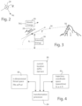
- FIG. 2 is a schematic representation of an aircraft, useful in understanding certain force vectors and angles used by the disclosed common schema and kinematic-energy models;
- FIG. 3 is a schematic representation of an aircraft, useful in understanding certain energy values used by the common schema and kinematic-energy models, and also showing a projected trajectory with exemplary energy and matter threats;
- FIG. 4 is a data model block diagram showing the relationship between the n-dimensional threat space and the trajectory coordinate space (spacetime);
- FIG. 5 is a detailed view of one viable and two deprecated trajectories, illustrating how the first-encountered trigger is used to initiate an aircraft protective response;
- FIG. 6 A is a graph of aircraft altitude vs terrain closure rate, illustrating regions where different pilot alert messages are commonly generated in prior art systems
- FIG. 6 B is a diagram of an aircraft flying above terrain, illustrating where prior art systems will typically issue different pilot alert messages, in the desired case where assumptions about terrain slope are reliable;
- FIG. 6 C is a diagram of an aircraft initially flying above terrain, illustrating where prior art systems will typically issue different pilot alert messages, in the undesired case where assumptions about terrain slope do not comport with the actual terrain, such that terrain collision is not avoided by the prior art system;
- FIG. 7 is an illustration showing how the projected trajectories are iteratively revised for threat avoidance.
- FIG. 8 is a block diagram of the non-binary collaborative recovery system.
- the disclosed aircraft flight envelope protection system uses flight path predictive techniques to provide unified, full-envelope protection, working across the entire spectrum of aircraft flight conditions to address a full spectrum of different types of hazards.
- Flight path predictions are computed continuously from the aircraft's current situation using a kinematic energy model.
- Plural predicted trajectories are calculated, each representing a different escape route that will recover from a hazard when the threshold or trigger point for that hazard is reached.
- the system respects different types of hazards, some dealing with innate aircraft properties, such as speed and altitude limits, and some dealing with external concerns, such as terrain and object avoidance.
- the disclosed aircraft flight envelope protection system is designed to work across all such threat envelope boundaries.
- the envelope protection system continually assesses, and deprecates trajectories that are not feasible in the aircraft's current situation.
- a deprecated trajectory is treated by the system as not viable, unless the aircraft's situation changes such that the deprecated trajectory again becomes viable.
- the disclosed protection system works in the background, and does not override or usurp the pilot's authority until only one viable predicted trajectory remains (all other predicted trajectories have been deprecated), and a threat is triggered. In this event, the protection system automatically deploys an autopilot mechanism to take evasive action to recover from the hazard condition.
- the protection system may also generate warnings to the pilot, but is preferably not dependent on the pilot to take recovery action once the one remaining viable trajectory reaches the trigger point.
- the predictive envelope protection system is configured to provide a non-binary spectrum of recovery actions, including a passenger-safe, soft-ride recovery at one end of the spectrum and a hard recovery at the other end of the spectrum.
- a non-binary spectrum of recovery actions including a passenger-safe, soft-ride recovery at one end of the spectrum and a hard recovery at the other end of the spectrum.
- the system triggers a hard recovery.
- the system triggers a soft recovery—a passenger safe, smooth recovery.
- the system will optionally blend input from the pilot into the recovery algorithm, allowing the pilot to modify the recovery aggressiveness based on the pilot's skill and experience.
- the non-binary collaborative recovery system is invoked when a threat is detected and the applicable (e.g., last remaining) projected trajectory is used. Details of the non-binary collaborative recovery system are shown in FIG. 7 discussed in the section entitled, Non-Binary and Collaborative Recovery below.
- an embodiment of the disclosed aircraft threat envelope protection system may be implemented using a processor 10 having an associated memory circuit 20 that is configured according to a predetermined threat envelope data structure 22 that stores a plurality of different types of threats associated with the aircraft 28 .
- the processor 10 and associated memory circuit 20 are carried by the aircraft.
- the data structure may comprise a table, list or matrix of records, each corresponding to a different threat type, shown in columnar form at 24 in FIG. 1 .
- Each threat type 24 has a corresponding trigger condition stored at 26 .
- These trigger conditions are parameterized using a common framework or common schema based on an n-dimensional threat space, and tell the processor 10 under what conditions the particular threat condition has been reached.
- the common schema dimensions of the threat space are chosen so that a full spectrum of different threat conditions can be represented using a common, minimal set of fundamental variables. A presently preferred minimal set of fundamental variables is discussed below in the section entitled Kinematic-Energy Model.
- the memory circuit 20 is also configured to support a trajectory coordinates data structure 30 that stores plural trajectories in terms of the spacetime coordinate variables 32 and threat type ID 34 .
- the spacetime coordinate variables have been identified using a rectangular coordinate system (x, y, z, t). Other coordinate systems (e.g., spherical) may also be used.
- the trajectory coordinates data structure is populated with a sequence of spacetime coordinate variables (separately for each projected trajectory being modeled) that lie on and thus define the recovery trajectory shape in spacetime.
- the processor 10 is programmed to perform the generate the projected trajectories step, at 40 , which results in a plurality of projected recovery trajectories being defined in terms of the spacetime coordinates, as illustrated in the spacetime illustration at 42 .
- Each projected trajectory is computed, taking the current state of the aircraft as the starting point and assuming that each recovery maneuver is initiated at that moment.
- three projected trajectories are generated by processor 10 .
- three projected trajectories will be illustrated.
- different numbers of trajectories may be used to define the working set of plural trajectories.
- three projected trajectories will normally be suitable to support smooth, passenger safe recoveries from threats.
- aircraft such as military aircraft, that may be required to fly inverted or in close proximity to the nape of the earth, a larger number of projected trajectories may desirable.
- the processor determines the spacetime shapes of each of the plural trajectories.
- the trajectory spacetime shapes follow a standardized set of predefined solution curves, corresponding to a set of known hazard recovery maneuvers that are appropriate for the class of aircraft for which the protection system is designed.
- these solution curves are based on what a trained pilot would likely fly to recover from the particular hazard.
- These might include, for example, a standard set of pull-up, dive, turn left and turn right maneuvers, where the specific parameters (e.g., climb and bank angles) are chosen to maximize passenger safety and comfort.
- compound recovery maneuvers may be used, where different classes of maneuvers are concatenated together.
- a business jet might employ a compound maneuver where a final climb maneuver is preceded by a zoom maneuver to exchange excess airspeed for altitude while capturing the optimum steady state climb.
- a standardized set of a relatively small number of predefined solution curves e.g., three projected trajectories
- processor can be programmed to compute a greater number of trajectories, and the calculations can be expanded to support additional variables.
- Parallel processing techniques and programmable gate array circuit components may be utilized to enhance or replace processor 10 if greater throughput is required.
- the processor can be programmed to select from a stored collection of different families of predefined solution curve sets, each family being designed for optimal recovery from a particular type or class of threat.
- the solution curve family chosen for recovery from a stall hazard might be different from the solution curve family chosen for recovery from a service ceiling hazard.
- the processor can project the current aircraft state onto the n-dimensional threat space to determine which threat family is most proximate to the current aircraft state. In so doing, the processor determines in real time which threat is most pressing and then bases the projected trajectory models on the family of predefined solution curves that is best suited under current circumstances.
- the processor at step 44 , associates applicable trigger points, corresponding to threats identified within the threat envelope data structure, to points in spacetime along each of the projected trajectories. For any given trajectory, initially there may be no detected threats. However, as the aircraft continues to fly and the trajectories are continually recomputed, at some point in time a threat may be detected and this threat (first detected in time) will be associated as a trigger point on each of the trajectories where applicable. As diagrammatically represented in the spacetime illustration at 46 , these trigger points represent points along the spacetime trajectory when the aircraft will reach the threat response margin for which evasive or recovery action should be initiated.
- the generated projected trajectories represent different hypothetical trajectories that the pilot (or an automated system) might elect to follow. Because each of these trajectories is being continually generated, they all represent possible future states of the aircraft. The current state of the aircraft lies at the starting point or singularity from which the projected future trajectories diverge. So long as there are plural projected trajectories available, the pilot remains free to follow whatever course he or she desires. Whatever course the pilot elects to fly, the processor 10 merely re-computes its solutions for the predetermined future trajectories.
- the processor 10 evaluates each of the projected trajectories on this basis, and decommissions or deprecates any trajectory that is no longer viable.
- FIG. 1 at 50 two of the projected trajectories are shown in dotted lines to indicate that they have been deprecated.
- Trajectories that have been deprecated are not used in a subsequent protective response. However, because the trajectory solutions are continually being updated by the processor, a deprecated trajectory could return to viability if the condition that caused it to be deprecated is lifted. For example if a trajectory was deprecated because it put the aircraft on collision course with another aircraft, and the other aircraft has since moved out of collision range, the processor will reinstate that trajectory as viable by removing its deprecation state.
- the processor initiates a protective response, shown at 54 .
- This response can include sending a warning or alert message to the pilot, which the pilot may heed or not.
- the protective response initiated by the processor is designed to set the aircraft on a computed trajectory that will avoid or escape from the first-encountered threat (if plural threats lie on the computed trajectory). To accomplish this the processor sends one or more commands to an autopilot system, the details of which will be discussed below.
- FIG. 5 illustrates this important hazard recovery response protocol in greater detail.
- one trajectory 60 remains viable, while trajectories 62 and 64 have been deprecated.
- the first-occurring threat 66 triggers the protective response to be initiated.
- the aircraft flies according to the projected trajectory.
- the projected trajectory becomes the actual trajectory instance that the aircraft will fly, subject to later changes (if any) from a subsequent iterative update of the projected trajectory.
- the projected trajectory is precomputed to clear any terrain threat, such as at 68 .
- the recipe used to compute the shape of the projected trajectory is designed to avoid the terrain threat at 68 .
- the presently preferred, minimal set of fundamental variables used by processor 10 relies upon a kinematic-energy model that defines a predictive trajectory in terms of the aircraft's physical position, its energy state, and the forces acting on the aircraft that affect trajectory.
- forces normal to the aircraft's longitudinal axis change the trajectory direction
- forces tangential to the aircraft's longitudinal axis change the aircraft's velocity along that trajectory.
- the common schema for the n-dimensional threat space can be represented by a minimal set of fundamental variables, N z , ⁇ , P s and ⁇ .
- N z represents the normal force (force acting normal or perpendicular to the longitudinal axis of the aircraft).
- the longitudinal axis of the aircraft 28 is directed into the page.
- This normal force N z also represents the g-force acting on the aircraft.
- the g-force acting on the aircraft is the force of gravity.
- the g-force orientation is changed.
- the kinetic energy 36 is derived from the true air speed (TAS); the potential energy 38 is derived from the aircraft altitude, specific excess power P s (available thrust power minus drag power) and the flight path angle ⁇ .
- the specific excess power P s is normalized to be independent of the aircraft weight, making P s a weight-independent energy term.
- ⁇ term represents the flight path angle (nose-up, nose-down angle).
- These variables may be used both to represent threats within the n-dimensional threat space 80 , shown in FIG. 4 and may also be used to calculate the aircraft's position and energy state at future positions in spacetime along a projected trajectory by using kinematic-energy relationships to transform data between the n-dimensional threat space 80 and the trajectory coordinate space 82 .
- the kinematic-energy relationship transformations are performed by the transformational processor 84 , which may be implemented by programming processor 10 with the kinematic-energy relationships that relate aircraft P s , N z , ⁇ , and ⁇ threat space values to the aircraft trajectory coordinates in spacetime (x, y, z, t).
- the disclosed predictive aircraft threat envelope protection system is able to provide full envelope protection because of its unique data model that can represent all threats using a common schema employing a minimal set of fundamental variables.
- the disclosed threat envelope protection system in essence employs a kinematic-energy data model based on a minimal set of variables and processor component that ties key components of the data model together.
- One key component of the data model defines the n-dimensional threat space 80 by which all threats are representing using a pair of force variables (Nz, ⁇ ) and a pair of energy state variables (Ps, ⁇ ).
- the threats to be protected against that are known a priori are pre-populated into the threat envelope data structure 22 ( FIG. 1 ).
- Threats known a priori would include, for example threats relating to different energy limits, such as stall limits, over-speed limits and under-speed limits. Some of these limits are known at the aircraft design time, while other limits are calculated during flight.
- Another key component of the data model defines the trajectory coordinate space in terms of spacetime variables (x, y, z, t).
- Some threats such as terrain objects and other aircraft (both examples of physical matter that occupy space) in the vicinity are more readily represented in coordinate space, based on the object's position.
- the system may utilize map data to store the physical location of terrain structures such as mountains that may be encountered during flight.
- the system is able to model both energy threats and matter threats.
- an energy threat 56 which could be, for example, an aircraft stall limit
- a matter threat 58 which could be a terrain object, such as a mountain).
- processor 10 ( FIG. 1 ) is programmed with the necessary kinematic equations to function as a transformation processor 84 that uses the current aircraft location 86 , obtained from suitable sensor such as GPS, and the force variables and energy state variables within threat space 80 , to calculate the projected trajectories in trajectory coordinate space 82 . If needed, the transformation processor can also project points in trajectory coordinate space 82 into threat space 80 , to assess for example whether the current or projected future location of the aircraft intersects with envelope threat limits.
- Full envelope protection provided by the disclosed aircraft flight envelope protection system involves two related aspects: (1) the protection afforded by the disclosed system covers all circumstances, not just the most common hazards; and (2) the disclosed system handles plural different threat conditions concurrently. It is not limited to a singular threat.
- the system is designed to provide protection in all circumstances not just in the heart of the flight envelope or for the most common hazards.
- a conventional overspeed protection system only works while near wings level. At very high bank angles, the overspeed protection is suppressed. The reason for this is logical.
- the overspeed protection works by pulling the nose up to help slow the aircraft. If the aircraft was at a very high bank angle, inverted for example, pulling the nose up can exasperate the problem instead of alleviating it.
- the full envelope protection afforded by the disclosed system does not have such limitations and works across the entire spectrum of aircraft flight conditions.
- the system is designed to provide full protection against all threats not just a single threat.
- TAWS enhanced ground proximity warning system
- protection is provided against ground impact.
- low speed protection is not provided—a separate low-speed protection system is conventionally provided for that.
- the disclosed aircraft flight envelope protection system provides protection against all threats in a single system. Handling all threats in a single system avoids conflicts that can arise with a collection of federated systems.
- FIG. 6 A An exemplary conventional TAWS system is illustrated in FIG. 6 A .
- This conventional TAWS uses radio altimeter altitude and rate of change to determine timing of the pull-up alert.
- FIG. 6 B Under nominal conditions, illustrated in FIG. 6 B , the alert will sound at a point that is not so early as to be a nuisance, but early enough for the pilot to react and initiate a climb that will clear the rising terrain. The accuracy of this method is dependent on two factors.
- FIG. 6 C illustrates what would happen if the terrain slope varied markedly from current slope.
- FIG. 6 C shows that if the terrain slope increases in front of the aircraft, terrain clearance may not be assured.
- the accuracy of this type of conventional system depends on the ability of the aircraft in its current configuration being able to fly the expected profile.
- the illustrated aircraft trajectory is assumed to be able to pull up above the rising terrain. This is an assumption that may or may not be accurate.
- the conventional TAWS system does not consider high altitude terrain where climb performance is significantly less than at sea level. It does not consider gross weight effects or engine failure conditions. The nominal case may not extend to the entire envelope.
- the disclosed predictive system does not rely on precomputed rules of thumb, but instead looks at the current conditions to predict climb performance. In the disclosed predictive system, the actual terrain in front of the aircraft is used and the actual climb capability is used.
- the significant factors affecting the climb capability of the aircraft are considered in real time and the actual terrain profile is compared to the current climb capability to determine an accurate warning initiation. While all factors affecting climb capability could be considered, in a practical embodiment it is usually only necessary to consider enough factors to ensure an adequate level of fidelity; insignificant factors having little impact can be excluded.
- the disclosed predictive aircraft flight envelope protection system uses kinematic modeling that focuses concern only with what happens and not why it happens.
- the disclosed system computes the relevant predictive trajectory from the physical position of the aircraft and its energy state.
- the disclosed system is not concerned with the forces or moments that cause that motion but only what the motion is.
- parameters such as elevator effectiveness, static longitudinal stability, short period frequency and damping ratio and many other parameters are of no significance.
- the disclosed predictive system only needs to concern itself with the forces that affect that trajectory.
- FIG. 3 illustrates a single iterative step in the modeling routine that uses kinematic modeling and energy-methods.
- the predictive method described above can be computationally intensive to perform real time so some techniques developed for the disclosed embodiment can be helpful.
- Computing calibrated airspeed (CAS) and Mach from the modeled true airspeed (TAS) can be computationally intensive.
- Computing accurate Ps can also be quite intensive.
- One technique to address these computational issues is to use a table lookup function.
- Another method is to perform a linear or second order curve fit of Ps as a function of altitude for the nominal case (250KCAS, Mid weight, STD . . . ) and then adjust that for off-nominal conditions using Ps debits.
- Such debits include, a debit for airspeed (as a function of altitude), a debit for Speed brakes, a debit for Single Engine, a debit for no standard day temp, etc. These can be added/subtracted from the computed debit. Many of the parameters can be computed only once during the modeling. For example, the latitudinal and longitudinal wind drift for each iteration of the model can be precomputed and used for each iteration that follows as the wind drift will be the same.
- the disclosed predictive system is a multi-trajectory system that in one preferred embodiment uses 3 primary trajectories to predict a warning/recovery initiation time.
- a single predictive trajectory system For a single predictive trajectory system, the system would look at current state and then assume a recovery would be initiated at that moment. The predictive recovery would then be modeled and tested for proximity to protected threats. For example, if the aircraft were in a dive toward the ground, the system would predict what the nose low recovery would look like and test that trajectory for proximity to both airspeed limits and terrain.
- the reason for supporting plural predictive trajectories can be illustrated by a second example in which the aircraft is flying level toward a single butte in the desert.
- plural predictive trajectories e.g., 6 trajectories in one preferred embodiment
- the pilot could avoid the butte by turning left or right to avoid it, or by staying on course and climbing above it. This raises the question, at what point should the system initiate a “PULL UP” warning? Perhaps not at all if a level turn is best.
- the solution to this problem is to use multiple trajectories. Since the pilot has multiple escape options, the system models each of those options.
- the system would model three trajectories, a left turning trajectory, a right turning trajectory, and a climbing trajectory. If a single trajectory violates a limit or has insufficient margins but the others are clear, no warning is issued as the pilot still has margin for another option. A warning is only issued when there is only one viable trajectory and that trajectory reaches a trigger point. So in the butte example, if the left and right turn are ruled out, a “PULL UP” will be issued when the climbing trajectory margins fall below a desired threshold. If due to a different approach or type of terrain, the climbing trajectory is ruled out, a “TURN LEFT” or “TURN RIGHT” warning will be issued when the respective trajectory is the last available and has reached its trigger margin.
- trajectories for one embodiment include a level climb, and 30 degree bank left and right climbing turns. Seven (7) trajectory and infinite trajectory systems may also be employed. These greater numbers of trajectories may have utility in military systems, for example, that require nape of the earth nuisance free operation.
- a level climb for example, may need to be preceded by a nose high recovery to attain climb speed before initiating the steady climb.
- the three final climbs are referred to as the final climb or the direct climb.
- the aircraft is always in a position to go directly into the final steady state climb. In business jets, the final climb will likely be preceded by a zoom to trade excess airspeed into altitude while capturing the optimum steady state climb.
- a nose low recovery must be initiated first where power is left back to keep airspeed under control before reaching an attitude where power can be brought to full for the final climb. Because the aircraft can perform nose high recoveries in two directions and nose low recoveries in two directions (rolling in shortest direction to level or rolling through the vertical to level) there are six total trajectories.
- the six trajectories are designated as primary trajectories. If desired, an embodiment may also support additional trajectories to accomplish other purposes. For example, once the preferred trajectory is found, it can be run again using a two-second pilot delay to help determine a more precise warning initiation. Also, if desired, the preferred trajectory may be computed again using a more aggressive recovery model. This more aggressive recovery model is then blended with the originally calculated preferred trajectory, to help blend between soft ride and hard ride recovery options.
- the predictive aircraft flight envelope protection system is a fully automatic system, which means that it does not rely on pilot intervention. While it can provide and probably should provide a warning to the pilot, the system is automatic and not dependent on the pilot heading that warning to provide protection. This requires a few additional considerations.
- An auto-pilot of some form needs to be implemented that executes an envelope protecting maneuver. That auto-pilot should have full authority over roll and pitch as well as speedbrake and throttle. Further, since the system must operate in one-engine-inoperative (OEI) cases, the auto-pilot must be able to handle asymmetric thrust conditions.
- the solution provided by the disclosed system is to add thrust compensation into the basic aircraft control laws.
- the aircraft behaves as if the thrust lines of both engines were along the centerline of the aircraft.
- the N1 difference between engines is used to schedule compensating rudder.
- thrust compensation There are other recognized methods of thrust compensation that can be used as an alternative to N1.
- a second necessary feature of an automatic system is that it must be much more resistant to failures and corrupted sensors than a manual system. With a manual system, the false warning can be easily ignored. With an automatic system, it cannot be ignored and therefore the resistance to false warnings must be significantly higher.
- the disclosed system thus provides multiple-redundant sensors combined with monitor circuits that determine when a sensor has failed or is suspect, and voter circuits that determine what sensor value is reported to the system when there is some variation between the multiple-redundant sensors.
- the automatic system allows pilot input to be blended with the control provided by the system.
- previous systems of this nature e.g., legacy automatic ground collision avoidance systems used in military applications
- the recovery is typically always nearly the maximum capability of the aircraft.
- the reasons for this derive from performance required for military applications, where nuisance free extreme low level operation (nape of the earth operation) was required without regard to ride quality.
- a business jet the opposite is true. Extreme low level, nape of the earth operations are not required and ride quality for passengers is of paramount importance.
- the preferred recovery for a business jet is typically nowhere near the maximum performance capability of the aircraft.
- the smooth, passenger safe recovery does create challenges, however.
- the system flexibly handles the extremes where the smooth, passenger safe recovery may not be appropriate: in one case allowing the system to automatically increase recovery aggressiveness, and in another case allowing the pilot to do so. To address these cases, the system implements a non-binary control system that will be described next.
- the auto-recovery or warning is either on or off, there are no middle states.
- the disclosed automatic system designed for business jet requires more.
- the solution is a non-binary system.
- the smooth, passenger safe soft ride is used but pilot blending is allowed and the soft ride will automatically blend into a harder and harder recovery if the margins degrade or fail to improve.
- One way to accomplish this is by comparing the soft ride preferred trajectory to the hard ride trajectory in the same direction and blending a nudger/fader based on that comparison.
- Other methods can be used where the margins to the limits can be used to drive the blending.
- the processor can assess if a smooth ride fails to achieve the margins desired. In such case the trajectory predicting algorithm incrementally increases aggressiveness and directs an increasingly more aggressive recovery in response.
- the nudger/fader design should be built such that pilots can aid the recovery but are progressively prevented from degrading the recovery when margins are small.
- a projected trajectory 60 a is illustrated as beginning when the aircraft is at location a.
- the projected trajectory 60 a simply represents a route calculated by the processor as being appropriate if a threat did happen to present itself.
- FIG. 7 only a single trajectory (e.g., 60 a ) is being illustrated. This FIG. 7 applies to both a multi-trajectory system, where other trajectories may already have been deprecated, and also to a single trajectory system where only one projected trajectory is computed.
- the aircraft proceeds forward in level flight along the dotted line until it reaches point b.
- point b the presence of a terrain hazard, such as mountain M is detected.
- the projected trajectory 60 b computed from the aircraft position at b, is adequate to avoid the mountain hazard by flying over it along the prescribed trajectory 60 b . All conditions being the same at point b as they were at point a, the shape of projected trajectory 60 b is the same as that of projected trajectory 60 a , computed moments before.
- Both trajectory 60 a and 60 b are computed by the processor using a smooth, passenger safe trajectory that exerts a nominal g-force on the aircraft passengers (e.g., 1.2 g).
- conditions may change such that when the aircraft reaches point c during flight, the projected trajectory 60 c —based on the same smooth, passenger safe trajectory parameters as trajectories 60 a and 60 b —is no longer adequate to clear the mountain M.
- Conditions may change, for example because of changes in air currents or because of actions taken by the pilot.
- the system still has time to correct for the inadequacy of trajectory 60 c and thus recomputes at point c a new trajectory 61 c that uses a more aggressive recovery formula which will permit a stronger g-force to be exerted on the aircraft passengers (e.g., 1.3 g).
- FIG. 8 illustrates one embodiment of the non-binary recovery hazard recovery system, implemented using a processor, such as processor 10 and associated components.
- the non-binary hazard recovery system is designed to supply flight commands to a flight control system 120 , which in turn controls the control surfaces, engines and other aircraft components that affect flight.
- the flight control system 120 receives an input from a signal blending or mixing circuit 122 (which may be implemented by processor 10 or as an external signal processing or logic gating circuit), to supply the flight control system with a blend of flight commands from the pilot and from the autopilot 124 .
- this blend of inputs may range from full pilot control to full autopilot control, with a variety of mixtures between where both pilot and autopilot affect what commands are sent to the flight control system 120 .
- the pilot input will typically be supplied via a inceptor or flight control stick 126 , the output of which is processed by the pilot input weighting attenuator 128 .
- the weighting attenuator receives a weight command from processor 10 , and this weight command is used to vary or attenuate the degree of pilot input, the attenuation factor ranging from 0% (no attenuation is applied) to 100% (no pilot signal is passed).
- the weighting attenuator can be designed to supply a linear attenuation range, a piecewise attenuation range, curve-fit range or the like.
- pilot attenuation can be considerably more complex than a mere numerical weighting factor.
- a blending schedule is stored in memory accessible by the processor 10 and this schedule is used to define to what degree pilot influence over the trajectory is permitted.
- This schedule would define a range (not necessarily a linear range) between gentle and hard recovery and may be stored in a lookup table for access by the processor.
- the processor can employ a blending schema selected from the group of schema including linear blending models, non-linear blending models and combinations of the two.
- the processor 10 also calculates the projected trajectory (such as those discussed in connection with FIG. 7 ). As described above, the processor generates the projected trajectory iteratively, each iteration starting at the aircraft's current position, shown in FIG. 8 as the origin o.
- the projected trajectories can be generated to produce a range of trajectories 60 having different degrees of flight aggressiveness. Although the general shape of the trajectory curves 60 are the same, the degree of aggressiveness is controlled by a recovery constraint property calculated by the processor by algorithm or lookup table.
- the processor determines the recovery constraint, and thus the proper degree of aggressiveness algorithmically by assessing how close the aircraft is to the detected threat, based on information from the threat detector system 130 .
- the threat detector system 130 illustrated here will in many instances be developed from a collection of different types of sensors, each selected to sense a property relevant to a particular type of threat.
- an airspeed sensor would provide detection of an over-speed or under-speed threat
- an active terrain sensor e.g, RADAR, LIDAR
- a map-based GPS enabled passive terrain would provide detection of a terrain collision threat.
- the processor 10 is programmed to repeatedly compute one or more projected trajectories through successive iterations. As discussed above, this is done even when there are no detected threats. Thus the projected trajectories serve as the potential starting point for executing a recovery maneuver in the event a threat is detected from one of the inputs of the detector system 130 .
- the processor will compute these projected trajectories using a recovery constraint property that will achieve a trajectory that is appropriate for the type of aircraft.
- the preferred initial trajectory is one that provides a smooth, passenger safe recovery at minimal g-force.
- the recovery constraint property may be changed later, if the initially computed recovery is not proving to be successful, but at first a smooth, passenger safe recovery is assumed to be appropriate by the system.
- the processor is programmed to supply the most recently computed projected trajectory to the autopilot 124 .
- the processor is programmed to allow full blended input from the pilot as well. This is achieved by setting the pilot attenuation factor to 0% (no attenuation).
- the autopilot 124 will supply flight instructions based on the most recently computed projected trajectory and these instructions will be blended at 122 with input from the pilot.
- the pilot elects to increase the aggressiveness of the recovery maneuver to sustain a higher g-force, that would be permitted.
- the pilot elects to countermand the autopilot maneuver, effectively cancelling the recovery trajectory being flown by the autopilot, that would also be permitted.
- the aircraft behavior set in motion by operation during this first post-detection iteration is not the end of the story. If during the next (or any subsequent iteration) the detector system 130 indicates that the currently executing trajectory will not avoid the hazard, a new more aggressive trajectory is calculated (using a different recovery constraint to increase aggressiveness) and a new attenuation factor is supplied to the pilot input weighting attenuator 128 to thereby reduce the degree to which the pilot can adversely alter the new trajectory.
- the weighting attenuator 128 can, for example, allow the pilot to increase the aggressiveness of the recovery even more than the new trajectory calls for, but restrict (or even fully prevent) the pilot's ability to decrease aggressiveness or take other action that would reduce the effectiveness of the new trajectory.
- the processor is programmed to revert to a blending state permitting the pilot input to have full or normal control over the aircraft.
- the non-binary collaborative recovery system thus continues to operate in this iterative fashion until a successful recovery solution is calculated and the aircraft clears the hazard.
- the degree of aggressiveness will increase, if needed, from the initial soft recovery (e.g., 1.2 g), to a more aggressive recovery (e.g., 1.3 g)—during which time some pilot input is accepted—and finally to a very aggressive recovery (e.g., 1.5 g to 2.0 g) during—during which time the pilot input is locked out.
- the system achieves a non-binary recovery that is not simply on or off.
- the recovery will automatically proceed in stages, at each iteration of the projected trajectory computation.
- the autopilot 124 component of the system the autopilot is not merely one or off; but rather it will perform increasingly aggressive recovery trajectories until the threat is cleared.
- a countermanding input from the pilot may have no bearing on whether the initially computed projected trajectory ends up being insufficient to clear the target.
- Conditions external to the aircraft may be the cause, such as changes in air turbulence, air pressure, wind speed, and the like.
- the non-binary aspect of the system allows the recovery trajectory to be adapted for optimal passenger comfort, given the current aircraft situation, as quickly as the processor can compute a fresh iteration, which it is normally designed to do continuously.
- Continuous iteration allows the the non-binary recovery system to permit collaborating input from the pilot. Collaboration is handled by the processor in an intelligent way, allowing pilot input with it is safe to do so, while gradually locking out pilot input when the safest course of action is to allow the autopilot to have full control.
- the blending system adjusts the ratio of pilot input to autopilot control signal input.
- the collaborative aspect of the disclosed system achieves a form of human-machine sensor fusion, where the autopilot system 124 is supplied with trajectory commands generated based on onboard aircraft sensors, terrain data and other technology systems.
- the human sensor i.e., the pilot
- the processor 10 and the blending or mixing circuit 122 perform sensor fusion of these two disparate sources (human and machine), to provide greater certainty that the aircraft trajectory is correct and will provide a smooth, passenger safe recovery, and in many cases, the optimal trajectory.
- both human capabilities and modern electronic signal processing capabilities are very capable; and yet in some important ways they are very different.
- the collaborative aspect of the disclosed system fuses these two disparate inputs to provide, in most cases, a better solution than would be possible with only one of the inputs alone.
- the system is designed as described above, so that during the initial iterations after detection of the hazard, the pilot input is permitted, possibly without any attenuation at all. In contrast, during later iterations the pilot input is attenuated, possibly locked out altogether, if the recovery trajectory is not working. Permitting pilot input during the initial iterations is advantageous, because pilots may sense aspects that the technology sensor systems have missed, and the pilot may have experience with the particular aircraft or the particular conditions that are more sophisticated than the processor could generate from technology sensors. However, during later iterations, if the threat is still present, attenuating pilot input is advantageous, because the pilot may be distracted or impaired.
Landscapes
- Engineering & Computer Science (AREA)
- Physics & Mathematics (AREA)
- General Physics & Mathematics (AREA)
- Aviation & Aerospace Engineering (AREA)
- Remote Sensing (AREA)
- Radar, Positioning & Navigation (AREA)
- Automation & Control Theory (AREA)
- Artificial Intelligence (AREA)
- Evolutionary Computation (AREA)
- Theoretical Computer Science (AREA)
- Life Sciences & Earth Sciences (AREA)
- Data Mining & Analysis (AREA)
- Business, Economics & Management (AREA)
- Health & Medical Sciences (AREA)
- Game Theory and Decision Science (AREA)
- Medical Informatics (AREA)
- Bioinformatics & Computational Biology (AREA)
- Atmospheric Sciences (AREA)
- General Engineering & Computer Science (AREA)
- Evolutionary Biology (AREA)
- Computer Vision & Pattern Recognition (AREA)
- Bioinformatics & Cheminformatics (AREA)
- Traffic Control Systems (AREA)
Abstract
Description
Claims (16)
Priority Applications (1)
| Application Number | Priority Date | Filing Date | Title |
|---|---|---|---|
| US16/552,634 US11592839B2 (en) | 2018-08-27 | 2019-08-27 | Non-binary collaborative recovery system |
Applications Claiming Priority (2)
| Application Number | Priority Date | Filing Date | Title |
|---|---|---|---|
| US201862723187P | 2018-08-27 | 2018-08-27 | |
| US16/552,634 US11592839B2 (en) | 2018-08-27 | 2019-08-27 | Non-binary collaborative recovery system |
Publications (3)
| Publication Number | Publication Date |
|---|---|
| US20200064835A1 US20200064835A1 (en) | 2020-02-27 |
| US20210397183A9 US20210397183A9 (en) | 2021-12-23 |
| US11592839B2 true US11592839B2 (en) | 2023-02-28 |
Family
ID=67953853
Family Applications (1)
| Application Number | Title | Priority Date | Filing Date |
|---|---|---|---|
| US16/552,634 Active 2040-07-26 US11592839B2 (en) | 2018-08-27 | 2019-08-27 | Non-binary collaborative recovery system |
Country Status (8)
| Country | Link |
|---|---|
| US (1) | US11592839B2 (en) |
| EP (1) | EP3844588A1 (en) |
| JP (1) | JP2021535037A (en) |
| CN (1) | CN112639653B (en) |
| BR (1) | BR112021003696A2 (en) |
| CA (1) | CA3109881A1 (en) |
| IL (1) | IL280997B2 (en) |
| WO (1) | WO2020046983A1 (en) |
Families Citing this family (2)
| Publication number | Priority date | Publication date | Assignee | Title |
|---|---|---|---|---|
| CN112865855B (en) * | 2021-01-04 | 2022-04-08 | 福州大学 | High-efficiency wireless covert transmission method based on unmanned aerial vehicle relay |
| US20230290256A1 (en) * | 2022-03-09 | 2023-09-14 | Lockheed Martin Corporation | Controlling aircraft to avoid terrain obstacles using reduced order closed loop models |
Citations (7)
| Publication number | Priority date | Publication date | Assignee | Title |
|---|---|---|---|---|
| US20040215372A1 (en) * | 2003-04-22 | 2004-10-28 | Bateman Charles D. | Aircraft autorecovery systems and methods |
| US20050073440A1 (en) * | 2003-09-18 | 2005-04-07 | Airbus France | Terrain Avoidance method and device for an aircraft |
| US20090082954A1 (en) * | 2007-09-25 | 2009-03-26 | Ridenour Ii Richard Darrell | Systems and methods for terrain warning suppression using flight plan information |
| US20100121503A1 (en) * | 2008-11-13 | 2010-05-13 | Saab Ab | Collision avoidance system and a method for determining an escape manoeuvre trajectory for collision avoidance |
| US20100292871A1 (en) * | 2009-03-26 | 2010-11-18 | The University Of North Dakota | Adaptive surveillance and guidance system for vehicle collision avoidance and interception |
| US9938018B2 (en) * | 2015-05-06 | 2018-04-10 | Aviation Safety Advancements, Inc. | Aircraft recovery control |
| US20180101180A1 (en) * | 2016-10-07 | 2018-04-12 | Sikorsky Aircraft Corporation | Simultaneous flight path control and attitude control with control axis splitting |
Family Cites Families (6)
| Publication number | Priority date | Publication date | Assignee | Title |
|---|---|---|---|---|
| US5716032A (en) * | 1996-04-22 | 1998-02-10 | United States Of America As Represented By The Secretary Of The Army | Unmanned aerial vehicle automatic landing system |
| US20100305784A1 (en) * | 2009-05-26 | 2010-12-02 | Anderson Thomas E | Embedded Ground Proximity Warning System for Helicopters |
| US9734724B2 (en) * | 2014-09-02 | 2017-08-15 | University Of Malta | Method and system for recovering the energy state of an aircraft during descent |
| CN106779294B (en) * | 2016-11-21 | 2019-04-23 | 中国商用飞机有限责任公司 | Airplane operation error detection method and system |
| CN106530840B (en) * | 2016-12-21 | 2019-06-14 | 中国航空工业集团公司雷华电子技术研究所 | A kind of flight based on aircraft real-time performance threatens bypassing method with hitting |
| CN106781707B (en) * | 2016-12-21 | 2019-11-22 | 华北计算技术研究所(中国电子科技集团公司第十五研究所) | A kind of path planning method for low latitude middle and long distance ferry flight |
-
2019
- 2019-08-27 IL IL280997A patent/IL280997B2/en unknown
- 2019-08-27 WO PCT/US2019/048398 patent/WO2020046983A1/en unknown
- 2019-08-27 US US16/552,634 patent/US11592839B2/en active Active
- 2019-08-27 EP EP19768940.9A patent/EP3844588A1/en active Pending
- 2019-08-27 CA CA3109881A patent/CA3109881A1/en active Pending
- 2019-08-27 BR BR112021003696-2A patent/BR112021003696A2/en unknown
- 2019-08-27 CN CN201980057208.8A patent/CN112639653B/en active Active
- 2019-08-27 JP JP2021510944A patent/JP2021535037A/en active Pending
Patent Citations (8)
| Publication number | Priority date | Publication date | Assignee | Title |
|---|---|---|---|---|
| US20040215372A1 (en) * | 2003-04-22 | 2004-10-28 | Bateman Charles D. | Aircraft autorecovery systems and methods |
| US20050073440A1 (en) * | 2003-09-18 | 2005-04-07 | Airbus France | Terrain Avoidance method and device for an aircraft |
| US20090082954A1 (en) * | 2007-09-25 | 2009-03-26 | Ridenour Ii Richard Darrell | Systems and methods for terrain warning suppression using flight plan information |
| US20100121503A1 (en) * | 2008-11-13 | 2010-05-13 | Saab Ab | Collision avoidance system and a method for determining an escape manoeuvre trajectory for collision avoidance |
| EP2187371A1 (en) | 2008-11-13 | 2010-05-19 | Saab Ab | Collision avoidance system and a method for determining an escape manoeuvre trajectory for collision avoidance |
| US20100292871A1 (en) * | 2009-03-26 | 2010-11-18 | The University Of North Dakota | Adaptive surveillance and guidance system for vehicle collision avoidance and interception |
| US9938018B2 (en) * | 2015-05-06 | 2018-04-10 | Aviation Safety Advancements, Inc. | Aircraft recovery control |
| US20180101180A1 (en) * | 2016-10-07 | 2018-04-12 | Sikorsky Aircraft Corporation | Simultaneous flight path control and attitude control with control axis splitting |
Non-Patent Citations (1)
| Title |
|---|
| Itoh Eri et al, Evaluation on Novel Architecture for Harmonizing manual and Automatic Flight Controls under Atmospheric Turbulence, Aerospace Science and Technology, Elsevier Masson, FR, vol. 24, No. 1, Nov. 25, 2011, pp. 241-254. |
Also Published As
| Publication number | Publication date |
|---|---|
| CN112639653A (en) | 2021-04-09 |
| CN112639653B (en) | 2024-03-12 |
| WO2020046983A1 (en) | 2020-03-05 |
| CA3109881A1 (en) | 2020-03-05 |
| IL280997A (en) | 2021-04-29 |
| EP3844588A1 (en) | 2021-07-07 |
| IL280997B1 (en) | 2023-12-01 |
| JP2021535037A (en) | 2021-12-16 |
| BR112021003696A2 (en) | 2021-05-18 |
| US20200064835A1 (en) | 2020-02-27 |
| IL280997B2 (en) | 2024-04-01 |
| US20210397183A9 (en) | 2021-12-23 |
Similar Documents
| Publication | Publication Date | Title |
|---|---|---|
| US11900824B2 (en) | Predictive aircraft flight envelope protection system | |
| US10228692B2 (en) | Aircraft flight envelope protection and recovery autopilot | |
| Swihart et al. | Automatic ground collision avoidance system design, integration, & flight test | |
| US11592839B2 (en) | Non-binary collaborative recovery system | |
| Aiello et al. | Run-time assurance for advanced flight-critical control systems | |
| US20200066166A1 (en) | Piecewise recovery system | |
| US11273928B2 (en) | Time available before aircraft auto-recovery begins | |
| Gahan | Multi-path automatic ground collision avoidance system for performance limited aircraft with flight tests: Project Have MEDUSA | |
| Frost et al. | Development of a reset algorithm for a helicopter shipboard landing guidance system | |
| Ikeda et al. | An optimal control problem for automatic air collision avoidance | |
| de Almeida et al. | On the maneuverability of small unmanned aerial vehicles | |
| Sharma et al. | Optimum Flight Trajectories and Sensitivity Analysis for Terrain Collision Avoidance Systems | |
| CN109903591A (en) | A kind of automatic near-earth collision assessment method and system of aircraft based on Expert Rules |
Legal Events
| Date | Code | Title | Description |
|---|---|---|---|
| FEPP | Fee payment procedure |
Free format text: ENTITY STATUS SET TO UNDISCOUNTED (ORIGINAL EVENT CODE: BIG.); ENTITY STATUS OF PATENT OWNER: LARGE ENTITY |
|
| AS | Assignment |
Owner name: GULFSTREAM AEROSPACE CORPORATION, GEORGIA Free format text: ASSIGNMENT OF ASSIGNORS INTEREST;ASSIGNORS:PROSSER, KEVIN;LANDERS, THOMAS;SAKHAEI, ALBORZ;AND OTHERS;REEL/FRAME:050405/0210 Effective date: 20190827 |
|
| STPP | Information on status: patent application and granting procedure in general |
Free format text: DOCKETED NEW CASE - READY FOR EXAMINATION |
|
| FEPP | Fee payment procedure |
Free format text: PETITION RELATED TO MAINTENANCE FEES GRANTED (ORIGINAL EVENT CODE: PTGR); ENTITY STATUS OF PATENT OWNER: LARGE ENTITY |
|
| STPP | Information on status: patent application and granting procedure in general |
Free format text: NON FINAL ACTION MAILED |
|
| STPP | Information on status: patent application and granting procedure in general |
Free format text: RESPONSE TO NON-FINAL OFFICE ACTION ENTERED AND FORWARDED TO EXAMINER |
|
| STPP | Information on status: patent application and granting procedure in general |
Free format text: FINAL REJECTION MAILED |
|
| STPP | Information on status: patent application and granting procedure in general |
Free format text: ADVISORY ACTION MAILED |
|
| STPP | Information on status: patent application and granting procedure in general |
Free format text: RESPONSE AFTER FINAL ACTION FORWARDED TO EXAMINER |
|
| STPP | Information on status: patent application and granting procedure in general |
Free format text: ADVISORY ACTION MAILED |
|
| STPP | Information on status: patent application and granting procedure in general |
Free format text: DOCKETED NEW CASE - READY FOR EXAMINATION |
|
| STPP | Information on status: patent application and granting procedure in general |
Free format text: NOTICE OF ALLOWANCE MAILED -- APPLICATION RECEIVED IN OFFICE OF PUBLICATIONS |
|
| STCF | Information on status: patent grant |
Free format text: PATENTED CASE |