US11575608B2 - Managing data flow between source node and recipient node - Google Patents
Managing data flow between source node and recipient node Download PDFInfo
- Publication number
- US11575608B2 US11575608B2 US17/181,508 US202117181508A US11575608B2 US 11575608 B2 US11575608 B2 US 11575608B2 US 202117181508 A US202117181508 A US 202117181508A US 11575608 B2 US11575608 B2 US 11575608B2
- Authority
- US
- United States
- Prior art keywords
- source node
- node
- recipient
- data
- data frames
- Prior art date
- Legal status (The legal status is an assumption and is not a legal conclusion. Google has not performed a legal analysis and makes no representation as to the accuracy of the status listed.)
- Active
Links
- 239000000872 buffer Substances 0.000 claims abstract description 107
- 238000000034 method Methods 0.000 claims abstract description 80
- 230000005540 biological transmission Effects 0.000 claims abstract description 78
- 230000006835 compression Effects 0.000 claims description 36
- 238000007906 compression Methods 0.000 claims description 36
- 238000004590 computer program Methods 0.000 claims description 13
- 238000010926 purge Methods 0.000 claims description 11
- 238000004891 communication Methods 0.000 description 24
- 230000003247 decreasing effect Effects 0.000 description 4
- 230000002829 reductive effect Effects 0.000 description 3
- 230000001413 cellular effect Effects 0.000 description 2
- 238000005516 engineering process Methods 0.000 description 2
- 230000000670 limiting effect Effects 0.000 description 2
- 238000012986 modification Methods 0.000 description 2
- 230000004048 modification Effects 0.000 description 2
- 230000036961 partial effect Effects 0.000 description 2
- 230000008569 process Effects 0.000 description 2
- 238000009877 rendering Methods 0.000 description 2
- 230000004044 response Effects 0.000 description 2
- 230000003068 static effect Effects 0.000 description 2
- 230000001360 synchronised effect Effects 0.000 description 2
- 230000006978 adaptation Effects 0.000 description 1
- 238000003491 array Methods 0.000 description 1
- 230000009286 beneficial effect Effects 0.000 description 1
- 230000008901 benefit Effects 0.000 description 1
- 230000010267 cellular communication Effects 0.000 description 1
- 238000013500 data storage Methods 0.000 description 1
- 230000001419 dependent effect Effects 0.000 description 1
- 239000000835 fiber Substances 0.000 description 1
- 238000011010 flushing procedure Methods 0.000 description 1
- 230000006870 function Effects 0.000 description 1
- 238000010295 mobile communication Methods 0.000 description 1
- 230000006855 networking Effects 0.000 description 1
- 230000003287 optical effect Effects 0.000 description 1
- 239000004065 semiconductor Substances 0.000 description 1
Images


Classifications
-
- H—ELECTRICITY
- H04—ELECTRIC COMMUNICATION TECHNIQUE
- H04L—TRANSMISSION OF DIGITAL INFORMATION, e.g. TELEGRAPHIC COMMUNICATION
- H04L47/00—Traffic control in data switching networks
- H04L47/10—Flow control; Congestion control
- H04L47/18—End to end
-
- H—ELECTRICITY
- H04—ELECTRIC COMMUNICATION TECHNIQUE
- H04L—TRANSMISSION OF DIGITAL INFORMATION, e.g. TELEGRAPHIC COMMUNICATION
- H04L47/00—Traffic control in data switching networks
- H04L47/10—Flow control; Congestion control
- H04L47/19—Flow control; Congestion control at layers above the network layer
- H04L47/193—Flow control; Congestion control at layers above the network layer at the transport layer, e.g. TCP related
-
- H—ELECTRICITY
- H04—ELECTRIC COMMUNICATION TECHNIQUE
- H04L—TRANSMISSION OF DIGITAL INFORMATION, e.g. TELEGRAPHIC COMMUNICATION
- H04L47/00—Traffic control in data switching networks
- H04L47/10—Flow control; Congestion control
-
- H—ELECTRICITY
- H04—ELECTRIC COMMUNICATION TECHNIQUE
- H04L—TRANSMISSION OF DIGITAL INFORMATION, e.g. TELEGRAPHIC COMMUNICATION
- H04L41/00—Arrangements for maintenance, administration or management of data switching networks, e.g. of packet switching networks
- H04L41/08—Configuration management of networks or network elements
- H04L41/0803—Configuration setting
- H04L41/0813—Configuration setting characterised by the conditions triggering a change of settings
- H04L41/0816—Configuration setting characterised by the conditions triggering a change of settings the condition being an adaptation, e.g. in response to network events
-
- H—ELECTRICITY
- H04—ELECTRIC COMMUNICATION TECHNIQUE
- H04L—TRANSMISSION OF DIGITAL INFORMATION, e.g. TELEGRAPHIC COMMUNICATION
- H04L43/00—Arrangements for monitoring or testing data switching networks
- H04L43/08—Monitoring or testing based on specific metrics, e.g. QoS, energy consumption or environmental parameters
- H04L43/0805—Monitoring or testing based on specific metrics, e.g. QoS, energy consumption or environmental parameters by checking availability
- H04L43/0817—Monitoring or testing based on specific metrics, e.g. QoS, energy consumption or environmental parameters by checking availability by checking functioning
-
- H—ELECTRICITY
- H04—ELECTRIC COMMUNICATION TECHNIQUE
- H04L—TRANSMISSION OF DIGITAL INFORMATION, e.g. TELEGRAPHIC COMMUNICATION
- H04L43/00—Arrangements for monitoring or testing data switching networks
- H04L43/08—Monitoring or testing based on specific metrics, e.g. QoS, energy consumption or environmental parameters
- H04L43/0852—Delays
-
- H—ELECTRICITY
- H04—ELECTRIC COMMUNICATION TECHNIQUE
- H04L—TRANSMISSION OF DIGITAL INFORMATION, e.g. TELEGRAPHIC COMMUNICATION
- H04L43/00—Arrangements for monitoring or testing data switching networks
- H04L43/08—Monitoring or testing based on specific metrics, e.g. QoS, energy consumption or environmental parameters
- H04L43/0876—Network utilisation, e.g. volume of load or congestion level
- H04L43/0882—Utilisation of link capacity
-
- H—ELECTRICITY
- H04—ELECTRIC COMMUNICATION TECHNIQUE
- H04L—TRANSMISSION OF DIGITAL INFORMATION, e.g. TELEGRAPHIC COMMUNICATION
- H04L43/00—Arrangements for monitoring or testing data switching networks
- H04L43/08—Monitoring or testing based on specific metrics, e.g. QoS, energy consumption or environmental parameters
- H04L43/0876—Network utilisation, e.g. volume of load or congestion level
- H04L43/0894—Packet rate
-
- H—ELECTRICITY
- H04—ELECTRIC COMMUNICATION TECHNIQUE
- H04L—TRANSMISSION OF DIGITAL INFORMATION, e.g. TELEGRAPHIC COMMUNICATION
- H04L43/00—Arrangements for monitoring or testing data switching networks
- H04L43/16—Threshold monitoring
-
- H—ELECTRICITY
- H04—ELECTRIC COMMUNICATION TECHNIQUE
- H04L—TRANSMISSION OF DIGITAL INFORMATION, e.g. TELEGRAPHIC COMMUNICATION
- H04L47/00—Traffic control in data switching networks
- H04L47/10—Flow control; Congestion control
- H04L47/24—Traffic characterised by specific attributes, e.g. priority or QoS
- H04L47/2416—Real-time traffic
-
- H—ELECTRICITY
- H04—ELECTRIC COMMUNICATION TECHNIQUE
- H04L—TRANSMISSION OF DIGITAL INFORMATION, e.g. TELEGRAPHIC COMMUNICATION
- H04L47/00—Traffic control in data switching networks
- H04L47/10—Flow control; Congestion control
- H04L47/26—Flow control; Congestion control using explicit feedback to the source, e.g. choke packets
- H04L47/263—Rate modification at the source after receiving feedback
-
- H—ELECTRICITY
- H04—ELECTRIC COMMUNICATION TECHNIQUE
- H04L—TRANSMISSION OF DIGITAL INFORMATION, e.g. TELEGRAPHIC COMMUNICATION
- H04L47/00—Traffic control in data switching networks
- H04L47/10—Flow control; Congestion control
- H04L47/30—Flow control; Congestion control in combination with information about buffer occupancy at either end or at transit nodes
-
- H—ELECTRICITY
- H04—ELECTRIC COMMUNICATION TECHNIQUE
- H04L—TRANSMISSION OF DIGITAL INFORMATION, e.g. TELEGRAPHIC COMMUNICATION
- H04L47/00—Traffic control in data switching networks
- H04L47/50—Queue scheduling
- H04L47/62—Queue scheduling characterised by scheduling criteria
- H04L47/6245—Modifications to standard FIFO or LIFO
-
- H—ELECTRICITY
- H04—ELECTRIC COMMUNICATION TECHNIQUE
- H04L—TRANSMISSION OF DIGITAL INFORMATION, e.g. TELEGRAPHIC COMMUNICATION
- H04L47/00—Traffic control in data switching networks
- H04L47/50—Queue scheduling
- H04L47/62—Queue scheduling characterised by scheduling criteria
- H04L47/625—Queue scheduling characterised by scheduling criteria for service slots or service orders
- H04L47/626—Queue scheduling characterised by scheduling criteria for service slots or service orders channel conditions
-
- H—ELECTRICITY
- H04—ELECTRIC COMMUNICATION TECHNIQUE
- H04L—TRANSMISSION OF DIGITAL INFORMATION, e.g. TELEGRAPHIC COMMUNICATION
- H04L49/00—Packet switching elements
- H04L49/90—Buffering arrangements
-
- H—ELECTRICITY
- H04—ELECTRIC COMMUNICATION TECHNIQUE
- H04L—TRANSMISSION OF DIGITAL INFORMATION, e.g. TELEGRAPHIC COMMUNICATION
- H04L47/00—Traffic control in data switching networks
- H04L47/10—Flow control; Congestion control
- H04L47/38—Flow control; Congestion control by adapting coding or compression rate
Definitions
- the present invention relates to managing a data flow between a source node and a recipient node.
- WO2018027237A1 discloses that multiple broadcasters create live streams of digital content relating to live events, and multiple viewers of each broadcaster receive copies of the live streams. Viewer latency is significantly reduced, and event information relating to live events is synchronized amongst all broadcasters and viewers of live streams relating to the same event. Scalable and flexible access to live streams is provided to different types and numbers of viewers with different qualities of service.
- a social media platform is provided in tandem with live streaming of digital content relating to live events, to allow a given broadcaster and their associated viewers to communicate with one another, comment on the event and/or the broadcasters live stream, and send digital gifts.
- the broadcasters' digital content includes video-based commentary regarding live sporting events, and studio-quality graphics and animations (including animated synchronized scorebugs) are provided on mobile client devices in tandem with the broadcasters' video-based commentary and social networking functionality.
- Real-time communications of data from a source to a recipient enables the recipient to have the most recent data generated at the source.
- Quality of the real-time data may be insufficient if the data rate supported between the source and the recipient is too low for high-quality data.
- the source and the recipient may connect over more than one data link that may be over wired or wireless connections, whereby variance of the data rate supported between the source and the recipient maybe relatively high.
- FIG. 1 illustrates a communications system for communications of data flow in accordance with at least some embodiments
- FIG. 2 illustrates a method in accordance with at least some embodiments
- FIG. 3 illustrates a method in accordance with at least some embodiments
- FIG. 4 illustrates a method in accordance with at least some embodiments
- FIG. 5 illustrates a method in accordance with at least some embodiments
- FIG. 6 illustrates a sequence for managing a data flow from a data source to a server in accordance with at least some embodiments
- FIG. 7 illustrates a sequence for managing a data flow from a server to viewer nodes in accordance with at least some embodiments
- FIG. 8 illustrates an example of an apparatus in accordance with at least some embodiments
- FIG. 9 illustrates a method in accordance with at least some embodiments.
- FIG. 10 illustrates managing a data flow from a source node to viewer nodes via a server in accordance with at least some embodiments.
- FIG. 11 illustrates examples of target parameters for viewer nodes.
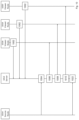
- FIG. 1 illustrates a communications system 100 for communications of data flow in accordance with at least some embodiments.
- the communications system may comprise one or more data sources 102 , 104 , 106 and one or more viewer nodes 112 , 113 , 114 , 115 116 , 118 .
- the data sources and viewer nodes may be connected to one or more servers 120 , 122 .
- the servers may be implemented as cloud servers and referred to clouds. Connections between the data sources and the servers, and connections between the servers and the viewer nodes may comprise one or more routers 133 , wired data links 134 , wireless data links 136 , radio access networks 132 , local area networks, sub-networks and/or wide area networks.
- connections may be heterogenous, whereby connections between each data source and viewer node may have different capabilities, for example in terms of the physical communications medium being a wireless medium or a wireless medium, in terms of supported data rates, delay performance and delay variance.
- the servers may be connected to the internet, whereby the data sources transmit data frames to the servers provided the data sources have Internet connectivity and the viewer nodes may be delivered data frames from the servers provided viewer nodes have internet connectivity.
- Examples of the wired data links 134 comprise at least Ethernet cables and fiber optic cables.
- Examples of the wireless data links 136 comprise at least wireless access links and wireless backhaul links of cellular radio access networks, relay links and wireless bridges.
- a cellular radio access network may be according to a cellular communications technology such as 3G, 4G or 5G defined by the 3GPP.
- Examples of the viewer nodes comprise user devices that comprise a user interface via which a user may consume content rendered on the basis of the communicated data flow.
- a user device may be user equipment of a mobile communications system, such as a mobile phone.
- a user device may be a computer workstation.
- the data sources may serve at least for source nodes in accordance with at least some embodiments described herein.
- the viewer nodes may serve at least for recipient nodes in accordance with at least some embodiments described herein.
- the servers may serve for source nodes and/or recipient nodes in accordance with at least some embodiments described herein. Connections between the source nodes and recipient nodes may comprise host-to-host protocol connections.
- a host-to-host protocol provides communications of data frames over a connection between communicating endpoints, in this case a source node and a recipient node that host protocol entities of the host-to-host protocol.
- data frames may be generated to be transmitted to the recipient node.
- data frames received from the source node may be consumed.
- the data frames may be processed by an analytics software application for machine-based processing the data frames from the source node and/or a software application for consuming the data frames by a user.
- the data frames may be processed by the software application that causes, playing the data frames in audio, video or displaying the data frames in still images, graphics and/or textual formal to the user.
- both the source node and the recipient node may host a protocol stack that comprises a host-to-host protocol, for example a transport layer protocol, e.g. the TCP or UDP, or a protocol above the transport layer, for communications of data frames between the source node and the recipient node.
- a host-to-host protocol for example a transport layer protocol, e.g. the TCP or UDP, or a protocol above the transport layer, for communications of data frames between the source node and the recipient node.
- Data flow may refer to real-time data that is generated at a source node.
- the real-time data may be generated by a Data Frame Generator (DFG).
- the DFG may be configured to generate data frames comprising still images, video and/or other computer-readable data such as positioning data.
- a data frame may comprise a header and a payload that carries the content, i.e. the still images, video and/or other computer-readable data such as positioning data.
- the header may comprise information for identifying the content, for example information identifying a compression format of the content and a source node of the content, a quality of the content and a size of the content.
- the header enables at least consuming the content at a recipient node.
- the quality and size of the content may be defined by a resolution.
- the resolution may be e.g. a resolution of still images or video.
- computer-readable data representing other content such as positioning data
- DFG Data Frame Generator
- Examples of the DFG comprise at least a still camera, a video camera and a positioning device, a camera application and a positioning application.
- the positioning device and positioning application may be configured to generate positioning data, for example Global Positioning System (GPS) data.
- GPS Global Positioning System
- An example of generating real-time data comprises at least generating data frames on the basis of data from a data source.
- data sources comprise at least a digital camera, a video camera and a positioning system (POS).
- POS positioning system
- a DFG may comprise a data source or be connected to one or more of the data sources for generating real-time data.
- the data from a data source may comprise at least data captured by a digital camera, a video camera and/or a positioning system.
- Real-time data may be captured at a source node for transmission by the source node to a recipient node.
- the real-time data may be stored to a transmission buffer hosted by the source node, where the real-time data may be retrieved for transmission to the recipient node.
- the real-time data may be transmitted from the source node to the recipient node without storing the real-time data for offline processing at source node.
- Real-time data stored to the transmission buffer may be managed on the basis of Last-in, First-Out (LIFO) method, where a unit or frame of real-time data stored to the buffer last is the first unit or frame of real-time data retrieved for transmission to the recipient node.
- LIFO Last-in, First-Out
- real-time data may be stored to the transmission buffer at a free position (POS) of the buffer whereby a memory pointer to the free position may be updated to the next free position (POS+1).
- POS free position
- POS+1 next free position
- the real-time data to be transmitted to the recipient node is retrieved from the buffer at (POS ⁇ 1) that points to the real-time data that has been stored to the transmission buffer the last.
- the recipient node may be provided real-time data, whenever the transmission is scheduled to from the source node to the recipient node. It should be noted that if a frame rate from the source node to the recipient node is slow, e.g.
- Viewer nodes may be host-to-host protocol endpoints at a server and/or at user devices.
- the viewer nodes are recipient nodes of data frames from source nodes.
- Examples of the viewer nodes at the server comprise at least analytics software applications for machine-based processing the data frames from the source node.
- Examples of the viewer nodes at the user devices comprise software applications, e.g. audio players, video players, that are operatively connected to one or more user interface devices configured at least for audio and/or video output to user.
- the software applications may be configured to cause rendering/playing content included to the data frames on the user devices such that the user may consume the content.
- Up-to-date situational awareness is used herein to refer to a recipient node being provided data frames of a data flow from one or more source nodes which enable the recipient node to have at each time instant the latest data frame generated by the source nodes.
- the situational awareness is provided by real-time communications of data frames with sufficient quality between the source nodes and the recipient node. In this way the recipient node and a user of the recipient node may have the latest data frame from each of the source nodes within a controlled delay after the data frames have been generated at each of the source nodes.
- FIG. 2 illustrates a method in accordance with at least some embodiments.
- the method provides managing a data flow between a source node and a recipient node.
- the method may be performed by the source node.
- the method supports up-to-date situational awareness by real-time communications of data frames with sufficient quality between the source node and the recipient node.
- Phase 202 comprises storing, at the source node, data frames into a buffer for transmission to the recipient node over a host-to-host protocol connection.
- Phase 204 comprises measuring, at the source node, a connection quality of the host-to-host protocol connection.
- Phase 206 comprises adjusting, at the source node, one or more target parameters of the transmission on the basis of the measured connection quality.
- the target parameters comprise at least a target frame rate, quality and compression format for the data frames.
- Phase 208 comprises transmitting, by the source node, data frames from the buffer to the recipient node on the basis of a Last-In, First-Out (LIFO) method and the adjusted one or more target parameters.
- the latest data frame is transmitted to the recipient, even if frame rate was reduced at phase 206 from a target frame rate, since the data frames are transmitted based on LIFO. Since the data frames are transmitted using the LIFO method, the newest data frame in the buffer is always transmitted to the recipient node.
- the adjusted target parameters provide that the data frames may be generated at a rate and quality that enables successful reception of the data frames at the recipient node. In this way real-time communications may be supported.
- phase 202 comprises, generating at the source node, the data frames on the basis of one or more target parameters.
- the target parameters comprise at least a target frame rate, size, quality and compression format of the data frames.
- the target parameters provide that generated data frames may be transmitted in real-time to the recipient node in accordance with phase 208 .
- the target parameters may have default values or the target parameters may be determined by the recipient node and used at the source node to set/adjust the parameters used at the source node.
- the data frames may be generated at a target frame rate that allows a generated data frame to be stored to the transmission buffer and transmitted, in accordance with phase 208 , before a next data frame according to the frame rate is stored to the transmission buffer.
- size of the transmission buffer may be kept small.
- a target size and/or quality of the generated frames may be limited to enable transmitting each data frame before the next is generated using the available bandwidth between the source node and the recipient node.
- the data frames may be generated at a target frame rate that allows storing a selected number of generated data frames to the transmission buffer before transmitting a data frame from the transmission buffer, in accordance with phase 208 .
- size of the transmission buffer may be designed based on the selected number of generated data frames and a selected duration for the data flow.
- a target size and/or quality of the generated frames may be higher than in the above example since a part of the generated data frames may be stored to the transmission buffer which leaves more time for transmitting the generated data, in accordance with phase 208 , at least when the available bandwidth is maintained.
- phase 204 comprises determining the connection quality on the basis of a success rate of real-time delivery of data frames from the source node to the recipient node.
- the success rate may be determined on the basis of success and/or unsuccessful transmissions of data frames over the host-to-host protocol connection in a time interval.
- the time interval may be determined sufficiently small such that failed transmissions of the data frames may be remedied by adjusting one or more of the target parameters in accordance with phase 206 and transmitting one or more further data frames using the adjusted one or more of the target parameters in accordance with phase 208 , whereby real-time delivery of data frames may be supported over the host-to-host protocol connection.
- the success rate may be determined at the source node on the basis of feedback information determined for each data frame transmitted over the host-to-host protocol connection.
- the feedback information may be received from the recipient node in accordance with the host-to-host protocol.
- the success rate may be determined on the basis of a number of frames in a time interval for which a negative feedback information has been received and/or no feedback information has been received.
- the success rate may be a percentage value between 0% to 100% or a category a set of success rate categories.
- the set of success rate categories comprises a full success rate, a partial success rate and a poor success rate.
- the success rate may be a full success rate, if the number of frames in a time interval for which a negative feedback information has been received and/or no feedback information has been received, is zero.
- the success rate may be a partial success rate, if the number of frames in a time interval for which a negative feedback information has been received and/or no feedback information has been received, is above zero.
- the success rate may be a poor success rate, if the number of frames in a time interval for which a negative feedback information has been received and/or no feedback information has been received, is the number of frames transmitted in the time interval, i.e. this indicates that all transmissions have been failed. Accordingly, the success rate may be implemented effectively as a counter that may be evaluated once in the time interval that is set for the success rate.
- the success rate may be evaluated against a threshold for determining a connection quality in phase 204 .
- a threshold is a number of consecutive data frames for which a negative feedback information has been received and/or no feedback information has been received in a time interval.
- the threshold may be a portion of frames in a time interval or a percentage value of data frame in a time interval for which no negative feedback information has been received and/or feedback information has been received.
- the connection quality in phase 204 may be measured on the basis of feedback information determined for each data frame transmitted over the host-to-host protocol connection.
- the feedback information may indicate a failure or a success of a transmission of a data frame. If feedback information for a given data frame is not received the feedback information for that data frame may be determined to indicate a failure. In this way a success rate may be determined.
- the success rate may be a ratio of frames for which feedback information has been received to a total number of frames.
- the connection quality may be determined on the basis of a selected feedback information. Accordingly, the feedback information for determining the connection quality may at least comprise the feedback information received for frames that have been transmitted after adjusting the one or more parameters the last time.
- one or more functionalities of the method described with FIG. 2 may be performed by an apparatus, e.g. a user device, that comprises a single buffer.
- the apparatus may serve as generator of data frames and delivery of the data frames to a plurality of viewer nodes may be achieved by the apparatus transmitting data frames to a server in accordance with phase 208 .
- one or more functionalities of the method described with FIG. 2 may be performed by an apparatus, e.g. a server, that manages delivery of data frames from data sources, for example user devices, to viewer nodes.
- the apparatus may host buffers, i.e. transmission buffers, for transmitting data frames to each of the viewer nodes and data flows to each of the viewer nodes may be managed in accordance to described with phases 202 to 208 . In this way real-time data delivery to each of the viewer nodes may be supported based on their individual connection qualities.
- FIG. 3 illustrates a method in accordance with at least some embodiments.
- the method provides managing a data flow between a source node and a recipient node.
- the method may be performed by the source node for example in connection with one or more phase of the method described with FIG. 2 .
- Phase 302 comprises transmitting, by the source node, data frames from the buffer to the recipient node using one or more target parameters.
- Phase 304 comprises receiving, at the source node, from the recipient node, feedback information for the transmitted data frames.
- Phase 306 comprises determining, at the source node, the connection quality of the transmitted data frames on the basis of received feedback information.
- Phase 308 comprises determining, at the source node, whether the connection quality meets a threshold.
- Phase 310 comprises adjusting, at the source node, the one or more of the target parameters, if the connection quality has not met the threshold.
- successful delivery of the data frames at the recipient node may be facilitated, whereby a data frame generated at the source node can be consumed in real-time at the recipient node.
- the adjusted target parameters provide that the data frames may be generated at a rate and quality that enables successful reception of the data frames at the recipient node. In this way real-time communications may be supported.
- the one or more target parameters at phase 302 comprise a target frame rate that may have been set by the recipient node.
- the recipient node may e.g. transmit a request to the source node to transmit using the target frame rate.
- phase 308 comprises that the threshold is for a success rate of real-time delivery of data frames from the source node to the recipient node. Then in phase 310 , if the success rate is not sufficiently high, the frame rate may be adjusted.
- phase 310 comprises that a target frame rate is decreased. In this way a number of data frames stored to the buffer may be increased since a fewer data frames are transmitted based on the LIFO method and the decreased frame rate.
- FIG. 4 illustrates a method in accordance with at least some embodiments.
- the method provides managing a data flow between a source node and a recipient node.
- the method may be performed by the source node.
- the method may be performed in connection with at least one of the phases described with FIG. 2 and FIG. 3 .
- Phase 402 comprises determining, at the source node that the connection quality exceeds the one or more of the target parameters.
- Phase 404 comprises transmitting, at the source node, to the recipient node at least one data frame stored into the buffer that is older than a previous data frame transmitted from the buffer.
- phase 402 comprises determining that a capability of the connection has increased.
- phase 402 comprises determining that a quality of the connection has increased.
- the connection quality may be higher than a threshold.
- a success rate may be higher than a threshold.
- phase 404 comprises that the buffer is emptied from data frames and the data frames are transmitted to the recipient node.
- the recipient node may reconstruct the data flow to include all the data frames buffered for transmission at the source node.
- FIG. 5 illustrates a method in accordance with at least some embodiments.
- the method provides managing a data flow between a source node and a recipient node.
- the method may be performed by the source node.
- the method may be performed in connection with at least one of the phases described with FIG. 2 and FIG. 3 .
- Phase 502 comprises receiving, by the source node, from the recipient node, information indicating a frame quality and size.
- the quality and size may be indicated by a resolution.
- Phase 504 comprises adjusting , at the source node, at least one of a compression format and a frame rate of data frames transmitted to the recipient node on the basis of the frame quality and size.
- the frame quality and size may be target parameters determined by the recipient node.
- the source node may adjust a compression format and a frame rate that are target parameters for data frames transmitted from the source node to the recipient node.
- the adjusted target parameters provide that the data frames may be generated at a rate and quality that enables successful reception of the data frames at the recipient node. In this way real-time communications may be supported.
- FIG. 6 illustrates a sequence for managing a data flow from a data source to a server in accordance with at least some embodiments.
- Phase 602 comprises the source node transmitting one or more data frames to the server over a host-to-host protocol connection using one or more target parameters.
- the server is a recipient node of the host-to-host protocol connection.
- the target parameters comprise at least a target frame rate, size, quality and compression format of the data frames.
- the target frame rate, the target size, quality and/or compression format cause generating at the source node data frames that have the target size, quality and/or compression format.
- the generated frames are stored to the LIFO buffer for transmission to a recipient node.
- the target size may be the size of the data frame of the host-to-host protocol, e.g. TOP frame or UDP frame.
- the target quality may be a quality, e.g. resolution, of the payload of the data frames of the host-to-host protocol, e.g. TCP frames or UDP frames.
- the target compression format may be a lossless compression format or a lossy compression format that has been applied to the payload of the data frames of the host-to-host protocol, e.g. TCP frames or UDP frames,
- Phase 604 comprises the server executing the host-to-host protocol between the data source and the server and transmitting an acknowledgement (ACK) in response to the data frames received from the data source.
- the ACK may be sent in response to each data frame received from the data source. In this way the data source may receive feedback information for the transmitted data frames from the server.
- Phase 606 comprises determining, at the data source, a connection quality of the transmitted data frames on the basis of received feedback information.
- the connection quality may be a success rate of real-time delivery of data frames to the server.
- Phase 608 comprises adjusting, at the data source, one or more of the target parameters, if the connection quality has not met a threshold.
- the threshold may be determined on the basis of one or more of the target parameters or adjusted target parameters. If the threshold has not been met, the adjusting may be omitted.
- Phase 610 comprises transmitting, by the data source, data frames to the recipient node on the basis of the one or more target parameters. It should be noted that the one or more of the target parameters may have been adjusted at phase 608 .
- Phase 612 comprises the data source receiving feedback information for the transmitted data frames from the server. Then, the connection quality may be determined anew at phase 606 .
- Phase 616 comprises the server determining the one or more target parameters and transmitting information indicating the determined one or more target parameters to the source node.
- the server may cause adjusting, at the source node, at phase 602 , the target parameters for the data frames and cause the data flow from the source node to be in accordance with the adjusted target parameters.
- the phase 616 may be performed before transmission of the data frames at phase 602 , whereby adjusting the one or more target parameters at phase 608 , may be reduced or even avoided, after the transmission of the data frames has begun from the source node to the server.
- FIG. 7 illustrates a sequence for managing a data flow from a server to viewer nodes in accordance with at least some embodiments.
- the sequence is illustrated between the server and one of the viewer nodes.
- the sequence may be performed in a similar manner between the server and other viewer nodes.
- the server is a source node of the host-to-host protocol connection and the viewer nodes are recipient nodes of the host-to-host protocol connection.
- Phase 702 comprises the server receiving from one of the viewer nodes, information indicating one or more target parameters.
- the one or more target parameters may be received included to a request for data frames. Examples of the target parameters are described with phase 602 and comprise at least a target frame rate, size, quality and compression format of the data frames.
- Phase 704 comprises adjusting, at the server, one or more target parameters for data frames transmitted to the viewer node on the basis of the received information and transmitting, by the server, data frames to the viewer node on the basis of the adjusted one or more parameters.
- Phase 708 comprises receiving, at the data source, from the viewer node, feedback information for the transmitted data frames.
- Phase 710 comprises determining, at the server, a connection quality of the transmitted data frames on the basis of the received feedback information.
- the connection quality may be a success rate of real-time delivery of data frames to the viewer node.
- Phases 712 and 714 comprise determining, at the server, whether the connection quality meets a threshold.
- Phase 712 comprises, if the connection quality has met the threshold, transmitting data frames to the viewer node without adjusting the one or more parameters.
- Phase 714 comprises, if the connection quality has not met the threshold, adjusting the one or more parameters and transmitting data frames to the viewer node on the basis of the adjusted one or more parameters.
- Phase 716 comprises receiving, at the server, from the viewer node, feedback information for the transmitted data frames in phase 712 or 714 . Then, the sequence may proceed to phase 710 for determining the connection quality anew on the basis of the feedback information received at phase 716 .
- the connection quality may be determined on the basis of a selected feedback information. Accordingly, the feedback information for determining the connection quality may at least comprise the feedback information received for frames that have been transmitted after adjusting the one or more parameters the last time.
- a method for managing data flows between a source node and a plurality of recipient nodes comprises performing the method in accordance with any of the methods described in connection with FIGS. 2 to 5 for managing data flow between the data source and each of the recipient nodes.
- data flows to each of the recipient nodes may be managed based on their connection qualities. This is beneficial at least, when data frames are communicated between the source node and the recipient node over heterogenous data links that may be have differences for example capabilities such as capabilities in terms of supported data rates, delay performance and delay variance.
- FIG. 8 illustrates an example of an apparatus in accordance with at least some embodiments of the present invention.
- the apparatus 800 may be a source node or a recipient node.
- the apparatus comprises a processor (P) 802 and a communications interface (CI) 806 .
- the processor is operatively connected to the communications interface for controlling the communications interface.
- the apparatus may comprise a memory (M) 804 .
- the memory may be operatively connected to the processor. It should be appreciated that the memory may be a separate memory or included to the processor and/or the CI.
- the CI may be a transceiver or connected to a transceiver or at least capable of being connected to a transceiver.
- the memory may store a computer program computer readable program code means for example computer program code, for execution by the processor. Execution of the computer readable program code means may cause the apparatus performing one or more functionalities described in an embodiment described herein.
- Examples of the apparatus 800 comprise a source node, a recipient node, a UE, and a server.
- the CI 806 may comprise one or more buffers, e.g. a transmission (TX) buffer.
- the buffers may be controlled by the processor and/or by the CI to process data frames on the basis of the LIFO method.
- the apparatus comprises a Data Frame Generator (DFG) 810 , a User Interface (UI) 810 and/or a positioning system (POS) 812 .
- the DFG may be configured to generate data frames. At least one of a frame rate, compression format of the data frames, size of the data frames, quality of the data frames and content of the data frames may be controlled by the processor at least based on target parameters.
- the, DFG may be configured to generate data frames comprising still images, video and/or positioning data.
- the DFG may comprise or be connected to a still camera and/or a video camera for obtaining still images and/or video for the data frames.
- the positioning data may be geographical coordinates, for example global Positioning System (GPS) coordinates.
- GPS global Positioning System
- the positioning data may be obtained from the POS.
- the POS may be a GPS device.
- the UI may provide output of information to a user and/or input of information to a user. Examples of the information output by the UI comprise data frames that may be displayed to the user. Examples of the input information comprise commands of the user.
- the UI may comprise a touch screen for both input and output of information.
- the UI may further comprise an audio output.
- the processor is configured to control the CI and/or to perform one or more functionalities described according to an embodiment.
- An apparatus for example a server, may comprise one or more apparatuses 800 for managing data flows between a source node and a plurality of recipient nodes.
- a data flow between the server, and each of the recipient nodes may be managed by a dedicated apparatus and connection quality specific to each of the connections may be observed in adjusting data rates over the connections.
- a memory may be a computer readable medium that may be non-transitory.
- the memory may be of any type suitable to the local technical environment and may be implemented using any suitable data storage technology, such as semiconductor-based memory devices, magnetic memory devices and systems, optical memory devices and systems, fixed memory and removable memory.
- the data processors may be of any type suitable to the local technical environment, and may include one or more of general purpose computers, special purpose computers, microprocessors, digital signal processors (DSPs) and processors based on multi-core processor architecture, as non-limiting examples.
- Embodiments may be implemented in software, hardware, application logic or a combination of software, hardware and application logic.
- the software, application logic and/or hardware may reside on memory, or any computer media.
- the application logic, software or an instruction set is maintained on any one of various conventional computer-readable media.
- a “memory” or “computer-readable medium” may be any media or means that can contain, store, communicate, propagate or transport the instructions for use by or in connection with an instruction execution system, apparatus, or device, such as a computer.
- FIG. 9 illustrates a method in accordance with at least some embodiments.
- the method provides managing a data flow between a source node and a recipient node.
- the method may be performed by the source node.
- the method may be performed in connection with at least one of the phases described with FIG. 2 and FIG. 3 .
- the method provides that data frames of a data flow that have not been transmitted to a recipient node in real-time may be delivered to the recipient node for reconstructing the data flow.
- Phase 902 comprises determining at least one of an end of data flow and an increased bandwidth to the recipient node.
- Phase 904 comprises purging the transmission buffer to the recipient node.
- the transmission buffer may be purged partially or the whole transmission buffer may be purged. The latter situation may also be referred to flushing the transmission buffer, which may take place, when the end of data flow has been determined.
- purging the transmission buffer partially provides efficient use of the increased bandwidth, and later, when the data flow ends, the less data frames are to be transmitted to the recipient node. Accordingly, purging the transmission buffer should be understood herein as a process of emptying at least partially a transmission queue of data frames in the transmission buffer.
- phase 902 comprises that an increased bandwidth is determined on the basis of receiving feedback information from the recipient node and determining that a time between the reception of the feedback information and a next frame to be stored to the transmission buffer at the target frame rate is higher than a time for transmitting at least one data frame stored to the transmission buffer.
- phase 904 comprises transmitting the data frames from the transmission buffer on the basis of a LIFO method or a First-in-First-out (FIFO) method.
- the FIFO method may be preferred for facilitating reconstructing the data flow from the beginning of the flow at the recipient node.
- FIG. 10 illustrates managing a data flow from a source node to viewer nodes via a server in accordance with at least some embodiments.
- a server 1012 may be configured to manage delivery of data frames from one or more source nodes 1014 , for example user devices, to one or more viewer nodes 1016 , 1018 , 1020 .
- a source node 1014 may be connected to the server 1012 over a host-to-host protocol for real-time delivery of data frames from the source node to the server.
- the server may host buffers, i.e. transmission buffers, for transmitting data frames to each of the viewer nodes and data flows to each of the viewer nodes may be managed in accordance with at least some embodiments described herein, e.g. with phases 202 to 208 in FIG. 2 . In this way real-time data delivery to each of the viewer nodes may be supported based on their individual connection qualities.
- the viewer nodes 1016 , 1018 , 1020 may be host-to-host protocol endpoints at the server and/or at user devices.
- Examples of the viewer nodes at the server comprise at least analytics software applications for machine-based processing the data frames from the source node.
- Examples of the viewer nodes at the user devices comprise software applications, e.g. audio players, video players, that are operatively connected to one or more user interface devices configured at least for audio and/or video output to user.
- the software applications may be configured to cause rendering/playing content included to the data frames on the user devices such that the user may consume the content. Since the data frames are delivered in real-time, the viewer nodes have the most recent data frame with a controlled/pre-define quality at their disposal. In this way an up-to-date situational awareness of the viewer nodes and analytics software applications may be supported.
- data frames may be first delivered from the source node 1014 to the server 1012 , whereby the server is a recipient node on the host-to-host protocol connection.
- the server may deliver the data frames received from the source node to the viewer nodes 1016 , 1018 , 1020 that have been subscribed for receiving data frames from the source node over a host-to-host protocol.
- the viewer nodes are recipient nodes and the server node is a source node between the host-to-host protocol connection between the server and the viewer nodes.
- Phase 1002 comprises the one or more viewer nodes 1016 , 1018 , 1020 subscribing to receive data frames from the source node 1014 over a host-to-host protocol connection to the server 1012 .
- the server may deliver data frames in real-time to the viewer node provided the server has received any data frames from the source node.
- communications of data frames between each of the viewer nodes and the server may be arranged in accordance with a method, e.g. the method according to phases 202 to 208 in FIG. 2 , described herein for supporting real-time communications of data frames from the server to each of the viewer nodes.
- Phase 1004 comprises the server 1012 receiving data frames from the source node. Communications of data frames between the source node and the server may be arranged in accordance with a method, e.g. the method according to phases 202 to 208 in FIG. 2 , described herein for supporting real-time communications of data frames from the source node to the server.
- Phase 1006 , 1008 , 1010 comprises the server transmitting data frames to each of the viewer nodes in accordance with a method, e.g. the method according to phases 202 to 208 in FIG. 2 , described in at least some embodiments herein for supporting real-time communications of data frames from the server to each of the viewer nodes.
- Phase 1022 comprises the server receiving data frames, when the source node 1014 purges its transmission buffer to the server node in accordance with the phases of the method described with FIG. 9 .
- FIG. 11 illustrates examples of target parameters for viewer nodes.
- the target parameters for viewer nodes illustrate target parameters for transmission from a source node different types of a recipient nodes, i.e. viewer nodes.
- Examples of the viewer nodes comprise an audio player software 1102 , a video player software 1104 and an analytics software 1106 .
- Each type of the viewer nodes may have respective target parameters 1108 , 1119 , 1112 , 1114 and corresponding ranges.
- Examples of the target parameters comprise a frame rate 1108 , a compression parameter 1110 , quality 1112 and compression format 1114 .
- the frame rate of the audio player software is defined in milliseconds (ms) within a range from 20 ms to 1000 ms
- the quality of the audio player software is defined by sample rate in Hz within a range from 8 kHz to 48 kHz
- the compression format is Opus, Advanced Audio Coding (AAC) or MPEG Layer III (MP3).
- the frame rate of the video player software is defined in frames per second (fps) within a range from 1 fps to 30 fps
- the quality of the video player software is defined by resolution within a range from 320 p to 4 k
- the compression format may be Webp, Jpeg, H264 or H265.
- the compression efficiency parameters for different viewer nodes refers to a quality setting of an encoding algorithm.
- the frame rate of the analytics software has scalable frame rate requirements
- the compression parameter is static
- the quality of the analytics software is static
- the compression format may be any.
- the frame rate 1108 and quality 1112 may be adjusted in steps within the given ranges for each of the examples of the viewer nodes and the compression format may be selected to be any of the options for compression format for each of the examples of the viewer nodes.
- FIG. 11 illustrates only some examples and in practice the ranges, options and values of the parameters may be different.
- adjusting one or more of the target parameters may comprise adjusting the target parameters within a given range of the parameter.
- the parameters may be adjusted in steps within the given range.
- the given ranges may be specific to viewer nodes according to the example of FIG. 11 .
- the adjusting may be performed on the basis of a connection quality, for example if the connection quality has not met the threshold.
- the compression and a frame rate of data frames transmitted to the recipient node may be adjusted on the basis of a frame quality and size.
- the frame quality and size may indicate the quality 1112 .
- a connection quality may be measured as described with phase 204 in FIG. 2 . If the connection quality has not met a threshold, the target parameters may be adjusted in accordance with phase 714 . When the connection quality has not met the threshold, the connection quality may be considered insufficient. When the connection quality is insufficient, transmission errors of data frames may be increased, which may prevent successful reception of the data frames and a data rate supported by a connection for transmission of the data frames may be low. Therefore, real-time communications of data frames with sufficient quality from a source to a recipient is challenging or may be prevented. Adjusting the target parameters supports real-time communications of data frames from the source node to the recipient node. In an example, if the connection quality has not met the threshold, e.g.
- one or more of the target parameters may be changed.
- the frame rate may be decreased and/or the quality may be decreased.
- the target parameters may be arranged in have predefined combinations of target parameters values that may be selected, when the target parameters are changed. Examples of the combinations comprise at least combinations of frame rate, quality and compression format.
- references to, where relevant, “computer-readable storage medium”, “computer program product”, “tangibly embodied computer program” etc., or a “processor” or “processing circuitry” etc. should be understood to encompass not only computers having differing architectures such as single/multi-processor architectures and sequencers/parallel architectures, but also specialized circuits such as field programmable gate arrays FPGA, application specify circuits ASIC, signal processing devices and other devices.
- References to computer readable program code means, computer program, computer instructions, computer code etc, should be understood to express software for a programmable processor firmware such as the programmable content of a hardware device as instructions for a processor or configured or configuration settings for a fixed function device, gate array, programmable logic device, etc.
- a method for managing a data flow between a source node and a recipient node comprising:
- a method for managing data flows between a source node and a plurality of recipient nodes comprising: performing the method in accordance with any of examples 1 to 6 for managing data flows between the data source and each of the recipient nodes.
- An apparatus comprising:
- An apparatus comprising:
- a computer program for managing a data flow between a source node and a recipient node comprising computer readable program code means adapted to perform at least the following, when executed at the source node:
- a computer program comprising computer readable program code means adapted to perform at least the following, when executed at a source node:
- a non-transitory computer readable medium comprising program instructions stored thereon for performing at least the following:
- non-transitory computer readable medium of any of examples 22 to 24 comprising program instructions stored thereon for performing:
- a non-transitory computer readable medium comprising program instructions stored thereon for performing at least the following:
- An apparatus for managing a data flow between a source node and a recipient node comprising:
- An apparatus comprising:
Abstract
Description
-
- storing, at the source node, data frames into a buffer for transmission to the recipient node over a host-to-host protocol connection;
- measuring, at the source node, a connection quality of the host-to-host protocol connection;
- adjusting, at the source node, one or more target parameters of the transmission on the basis of the measured connection quality;
- transmitting, by the source node, data frames from the buffer to the recipient node on the basis of a Last-In, First-Out (LIFO) method and the adjusted one or more target parameters.
-
- transmitting, by the source node, data frames from the buffer to the recipient node using one or more target parameters;
- receiving, at the source node, from the recipient node, feedback information for the transmitted data frames;
- determining, at the source node, the connection quality of the transmitted data frames on the basis of received feedback information;
- determining, at the source node, whether the connection quality meets a threshold; and
- adjusting, at the source node, the one or more of the target parameters, if the connection quality has not met the threshold.
-
- determining, at the source node, that the connection quality exceeds the one or more of the target parameters;
- transmitting, at the source node, to the recipient node at least one data frame stored into the buffer that is older than a previous data frame transmitted from the buffer.
-
- receiving, by the source node, from the recipient node, information indicating a frame quality and size;
- adjusting, at the source node, a compression format and a frame rate of data frames transmitted to the recipient node on the basis of the frame quality and size.
-
- determining the connection quality on the basis of a success rate of real-time delivery of data frames from the source node to the recipient node over the host-to-host protocol connection.
-
- determining at least one of an end of data flow and an increased bandwidth to the recipient node;
- purging the transmission buffer to the recipient node.
-
- means for managing a data flow between a source node and a recipient node;
- means for storing, at the source node, data frames into a buffer for transmission to the recipient node over a host-to-host protocol connection;
- means for measuring, at the source node, a connection quality of the host-to-host protocol connection
- means for adjusting, at the source node, one or more target parameters of the transmission on the basis of the measured connection quality
- means for transmitting, by the source node, data frames from the buffer to the recipient node on the basis of a Last-In, First-Out (LIFO) method and the adjusted one or more target parameters.
-
- means for transmitting, by the source node, data frames from the buffer to the recipient node using one or more target parameters
- means for receiving, at the source node, from the recipient node, feedback information for the transmitted data frames
- means for determining, at the source node, the connection quality of the transmitted data frames on the basis of received feedback information
- means for determining, at the source node, whether the connection quality meets a threshold and
- means for adjusting, at the source node, the one or more of the target parameters, if the connection quality has not met the threshold .
-
- means for determining, at the source node, that the connection quality exceeds the one or more of the target parameters
- means for transmitting, at the source node, to the recipient node at least one data frame stored into the buffer that is older than a previous data frame transmitted from the buffer .
-
- means for receiving, by the source node, from the recipient node, information indicating a frame quality and size
- means for adjusting , at the source node, a compression format and a frame rate of data frames transmitted to the recipient node on the basis of the frame quality and size .
-
- means for determining the connection quality on the basis of a success rate of real-time delivery of data frames over the host-to-host protocol connection.
-
- means for determining at least one of an end of data flow and an increased bandwidth to the recipient node;
- means for purging the transmission buffer to the recipient node.
-
- means for managing data flows between a source node and a plurality of recipient nodes, comprising the apparatus in accordance with any examples 8 to 13 for managing data flows between the data source and each of the recipient nodes.
-
- storing, at the source node, data frames into a buffer for transmission to the recipient node over a host-to-host protocol connection;
- measuring, at the source node, a connection quality of the host-to-host protocol connection;
- adjusting, at the source node, one or more target parameters of the transmission on the basis of the measured connection quality;
- transmitting, by the source node, data frames from the buffer to the recipient node on the basis of a Last-In, First-Out (LIFO) method and the adjusted one or more target parameters.
-
- transmitting, by the source node, data frames from the buffer to the recipient node using one or more target parameters;
- receiving, at the source node, from the recipient node, feedback information for the transmitted data frames;
- determining, at the source node, the connection quality of the transmitted data frames on the basis of received feedback information;
- determining, at the source node, whether the connection quality meets a threshold; and
- adjusting, at the source node, the one or more of the target parameters, if the connection quality has not met the threshold.
-
- determining, at the source node, that the connection quality exceeds the one or more of the target parameters;
- transmitting, at the source node, to the recipient node at least one data frame stored into the buffer that is older than a previous data frame transmitted from the buffer.
-
- receiving, by the source node, from the recipient node, information indicating a frame quality and size;
- adjusting , at the source node, a compression format and a frame rate of data frames transmitted to the recipient node on the basis of the frame quality and size.
-
- determining the connection quality on the basis of a success rate of real-time delivery of data frames over the host-to-host protocol connection
-
- determining at least one of an end of data flow and an increased bandwidth to the recipient node;
- purging the transmission buffer to the recipient node.
-
- managing data flows between the source node and a plurality of recipient nodes, comprising: performing the method in accordance with any of examples 1 to 6 for managing data flows between the data source and each of the recipient nodes.
-
- managing a data flow between a source node and a recipient node;
- for storing, at the source node, data frames into a buffer for transmission to the recipient node over a host-to-host protocol connection;
- measuring, at the source node, a connection quality of the host-to-host protocol connection;
- adjusting, at the source node, one or more target parameters of the transmission on the basis of the measured connection quality;
- transmitting, by the source node, data frames from the buffer to the recipient node on the basis of a Last-In, First-Out (LIFO) method and the adjusted one or more target parameters.
-
- transmitting, by the source node, data frames from the buffer to the recipient node using one or more target parameters;
- receiving, at the source node, from the recipient node, feedback information for the transmitted data frames;
- determining, at the source node, the connection quality of the transmitted data frames on the basis of received feedback information;
- determining, at the source node, whether the connection quality meets a threshold; and
- adjusting, at the source node, the one or more of the target parameters, if the connection quality has not met the threshold.
-
- determining, at the source node, that the connection quality exceeds the one or more of the target parameters;
- transmitting, at the source node, to the recipient node at least one data frame stored into the buffer that is older than a previous data frame transmitted from the buffer .
-
- receiving, by the source node, from the recipient node, information indicating a frame quality and size;
- adjusting , at the source node, a compression format and a frame rate of data frames transmitted to the recipient node on the basis of the frame quality and size .
-
- determining at least one of an end of data flow and an increased bandwidth to the recipient node;
- purging the transmission buffer to the recipient node.
-
- managing data flows between a source node and a plurality of recipient nodes, comprising: performing the method in accordance with any of examples 1 to 6 for managing data flows between the data source and each of the recipient nodes.
-
- one or more processors, and memory storing instructions that, when executed by the one or more processors, the apparatus is caused to:
- store, at the source node, data frames into a buffer for transmission to the recipient node over a host-to-host protocol connection;
- measure, at the source node, a connection quality of the host-to-host protocol connection;
- adjust, at the source node, one or more target parameters of the transmission on the basis of the measured connection quality;
- transmit, by the source node, data frames from the buffer to the recipient node on the basis of a Last-In, First-Out (LIFO) method and the adjusted one or more target parameters.
-
- transmit, by the source node, data frames from the buffer to the recipient node using one or more target parameters;
- receive, at the source node, from the recipient node, feedback information for the transmitted data frames;
- determine, at the source node, the connection quality of the transmitted data frames on the basis of received feedback information;
- determine, at the source node, whether the connection quality meets a threshold; and
- adjust, at the source node, the one or more of the target parameters, if the connection quality has not met the threshold.
-
- determine, at the source node, that the connection quality exceeds the one or more of the target parameters;
- transmit, at the source node, to the recipient node at least one data frame stored into the buffer that is older than a previous data frame transmitted from the buffer.
-
- receive, by the source node, from the recipient node, information indicating a frame quality and size;
- adjust , at the source node, a compression format and a frame rate of data frames transmitted to the recipient node on the basis of the frame quality and size.
-
- determine the connection quality on the basis of a success rate of real-time delivery of data frames over the host-to-host protocol connection.
-
- determine at least one of an end of data flow and an increased bandwidth to the recipient node;
- purge the transmission buffer to the recipient node.
-
- one or more processors, and memory storing instructions that, when executed by the one or more processors, the apparatus is caused to: managing data flows between a source node and a plurality of recipient nodes, comprising: performing the method in accordance with any of examples 1 to 6 for managing data flows between the data source and each of the recipient nodes.
Claims (11)
Applications Claiming Priority (2)
| Application Number | Priority Date | Filing Date | Title |
|---|---|---|---|
| FI20206368 | 2020-12-23 | ||
| FI20206368A FI129689B (en) | 2020-12-23 | 2020-12-23 | Managing data flow between source node and recipient node |
Publications (2)
| Publication Number | Publication Date |
|---|---|
| US20220200909A1 US20220200909A1 (en) | 2022-06-23 |
| US11575608B2 true US11575608B2 (en) | 2023-02-07 |
Family
ID=79316998
Family Applications (1)
| Application Number | Title | Priority Date | Filing Date |
|---|---|---|---|
| US17/181,508 Active US11575608B2 (en) | 2020-12-23 | 2021-02-22 | Managing data flow between source node and recipient node |
Country Status (3)
| Country | Link |
|---|---|
| US (1) | US11575608B2 (en) |
| EP (1) | EP4020931A1 (en) |
| FI (1) | FI129689B (en) |
Families Citing this family (1)
| Publication number | Priority date | Publication date | Assignee | Title |
|---|---|---|---|---|
| US20230135386A1 (en) * | 2021-11-02 | 2023-05-04 | Fortinet, Inc. | Remote cost based network traffic steering for heterogeneous links in a sdwan (software defined wide area network) |
Citations (11)
| Publication number | Priority date | Publication date | Assignee | Title |
|---|---|---|---|---|
| WO1999000984A1 (en) | 1997-06-26 | 1999-01-07 | Citrix Systems, Inc. | System for adaptive video/audio transport over a network |
| US20090024809A1 (en) | 2007-07-16 | 2009-01-22 | Apple Inc. | Managing Purgeable Memory Objects |
| US20100061238A1 (en) * | 2008-09-11 | 2010-03-11 | Avanindra Godbole | Methods and apparatus for flow control associated with multi-staged queues |
| WO2010060106A1 (en) | 2008-11-24 | 2010-05-27 | Ankeena Networks, Inc., | Adaptive network content delivery system |
| US20110013514A1 (en) | 2008-03-12 | 2011-01-20 | Telefonaktiebolaget Lm Ericsson (Publ) | Device and Method for Adaptation of Target Rate of Video Signals |
| US20150347340A1 (en) * | 2014-05-30 | 2015-12-03 | International Business Machines Corporation | Intercomponent data communication |
| US20170230861A9 (en) | 2002-05-10 | 2017-08-10 | Signal Trust For Wireless Innovation | Cognitive flow control based on channel quality conditions |
| WO2018027237A1 (en) | 2016-08-05 | 2018-02-08 | Sportscastr.Live Llc | Systems, apparatus, and methods for scalable low-latency viewing of broadcast digital content streams of live events |
| US20190158371A1 (en) * | 2017-11-22 | 2019-05-23 | Hughes Network Systems, Llc | Latency increase estimated rate limiter adjustment |
| US20190327463A1 (en) * | 2016-12-30 | 2019-10-24 | SZ DJI Technology Co., Ltd. | System and methods for feedback-based data transmission |
| US20200107069A1 (en) | 2018-09-28 | 2020-04-02 | Apple Inc. | Systems and methods for reducing latency of a video transmission system |
-
2020
- 2020-12-23 FI FI20206368A patent/FI129689B/en active IP Right Grant
-
2021
- 2021-02-22 US US17/181,508 patent/US11575608B2/en active Active
- 2021-12-21 EP EP21216281.2A patent/EP4020931A1/en active Pending
Patent Citations (11)
| Publication number | Priority date | Publication date | Assignee | Title |
|---|---|---|---|---|
| WO1999000984A1 (en) | 1997-06-26 | 1999-01-07 | Citrix Systems, Inc. | System for adaptive video/audio transport over a network |
| US20170230861A9 (en) | 2002-05-10 | 2017-08-10 | Signal Trust For Wireless Innovation | Cognitive flow control based on channel quality conditions |
| US20090024809A1 (en) | 2007-07-16 | 2009-01-22 | Apple Inc. | Managing Purgeable Memory Objects |
| US20110013514A1 (en) | 2008-03-12 | 2011-01-20 | Telefonaktiebolaget Lm Ericsson (Publ) | Device and Method for Adaptation of Target Rate of Video Signals |
| US20100061238A1 (en) * | 2008-09-11 | 2010-03-11 | Avanindra Godbole | Methods and apparatus for flow control associated with multi-staged queues |
| WO2010060106A1 (en) | 2008-11-24 | 2010-05-27 | Ankeena Networks, Inc., | Adaptive network content delivery system |
| US20150347340A1 (en) * | 2014-05-30 | 2015-12-03 | International Business Machines Corporation | Intercomponent data communication |
| WO2018027237A1 (en) | 2016-08-05 | 2018-02-08 | Sportscastr.Live Llc | Systems, apparatus, and methods for scalable low-latency viewing of broadcast digital content streams of live events |
| US20190327463A1 (en) * | 2016-12-30 | 2019-10-24 | SZ DJI Technology Co., Ltd. | System and methods for feedback-based data transmission |
| US20190158371A1 (en) * | 2017-11-22 | 2019-05-23 | Hughes Network Systems, Llc | Latency increase estimated rate limiter adjustment |
| US20200107069A1 (en) | 2018-09-28 | 2020-04-02 | Apple Inc. | Systems and methods for reducing latency of a video transmission system |
Non-Patent Citations (4)
| Title |
|---|
| Extended European Search Report, dated May 13, 2022, received in connection with corresponding EP Patent Application No. 21216281.2. |
| Hu, N., et al., "Improving TCP Startup Performance using Active Measurements: Algorithm and Evaluation," Proceedings of the 11th IEEE International Conference on Network Protocols (ICNP'03), 2003, pp. 107-118. |
| Liu, Y., et al., "TCP-CM: A Transport Protocol for TCP-friendly Transmission of Continuous Media," Proceedings of the 2002 IEEE International Conference on Performance, Computing and Communications (IPCCC), 2002, pp. 83-91. |
| Office Action issued in corresponding Finnish Patent Application No. 20206368 dated May 14, 2021. |
Also Published As
| Publication number | Publication date |
|---|---|
| FI129689B (en) | 2022-06-30 |
| US20220200909A1 (en) | 2022-06-23 |
| EP4020931A1 (en) | 2022-06-29 |
| FI20206368A1 (en) | 2022-06-24 |
Similar Documents
| Publication | Publication Date | Title |
|---|---|---|
| KR102324326B1 (en) | Streaming multiple encodings encoded using different encoding parameters | |
| US9077774B2 (en) | Server-assisted video conversation | |
| US10057014B2 (en) | System and method for streaming data | |
| US9407387B2 (en) | Apparatus and method for synchronized transmission of multimedia content over an asynchronous network | |
| US10771821B2 (en) | Overcoming lost IP packets in streaming video in IP networks | |
| US20150271231A1 (en) | Transport accelerator implementing enhanced signaling | |
| EP3127287B1 (en) | Signaling and operation of an mmtp de-capsulation buffer | |
| TW201427391A (en) | Media streaming method, device therewith and device for providing the media streaming | |
| US11201903B1 (en) | Time synchronization between live video streaming and live metadata | |
| CN110198311B (en) | Data stream processing method, device, equipment and medium | |
| WO2019055275A1 (en) | Handling media timeline offsets | |
| EP4020931A1 (en) | Managing data flow between source node and recipient node | |
| CN113905257A (en) | Video code rate switching method and device, electronic equipment and storage medium | |
| CN116018806A (en) | Separate rendering to improve tolerance to delay variation in augmented reality applications with remote rendering | |
| US9697328B2 (en) | Transmission apparatus, transmission method, reception apparatus, reception method, and computer program | |
| Selinis et al. | On the Internet-scale streaming of holographic-type content with assured user quality of experiences | |
| US10070017B2 (en) | Controlling synchronization between devices in a network | |
| US11503354B2 (en) | Methods and apparatus for streaming data | |
| US11910033B2 (en) | Streaming server, transmission method, and program | |
| US11409415B1 (en) | Frame interpolation for media streaming | |
| US20230403240A1 (en) | Generating mission-specific analytics information | |
| JP2018152656A (en) | Transmission apparatus, video distribution apparatus, video coding apparatus, and transmission method | |
| EP3316531A1 (en) | Method to transmit an audio/video stream of to a destination device | |
| FI20236295A1 (en) | Generating mission-specific analytics information | |
| US11917327B2 (en) | Dynamic resolution switching in live streams based on video quality assessment |
Legal Events
| Date | Code | Title | Description |
|---|---|---|---|
| AS | Assignment |
Owner name: NSION OY, FINLAND Free format text: ASSIGNMENT OF ASSIGNORS INTEREST;ASSIGNORS:KRONQVIST, MATTIPEKKA;BLANKENSTEIN, JUHO;ERONEN, MARKUS;SIGNING DATES FROM 20210205 TO 20210211;REEL/FRAME:055360/0779 |
|
| FEPP | Fee payment procedure |
Free format text: ENTITY STATUS SET TO UNDISCOUNTED (ORIGINAL EVENT CODE: BIG.); ENTITY STATUS OF PATENT OWNER: SMALL ENTITY |
|
| FEPP | Fee payment procedure |
Free format text: ENTITY STATUS SET TO SMALL (ORIGINAL EVENT CODE: SMAL); ENTITY STATUS OF PATENT OWNER: SMALL ENTITY |
|
| STPP | Information on status: patent application and granting procedure in general |
Free format text: FINAL REJECTION MAILED |
|
| STPP | Information on status: patent application and granting procedure in general |
Free format text: RESPONSE AFTER FINAL ACTION FORWARDED TO EXAMINER |
|
| STPP | Information on status: patent application and granting procedure in general |
Free format text: ADVISORY ACTION MAILED |
|
| STPP | Information on status: patent application and granting procedure in general |
Free format text: DOCKETED NEW CASE - READY FOR EXAMINATION |
|
| STPP | Information on status: patent application and granting procedure in general |
Free format text: NOTICE OF ALLOWANCE MAILED -- APPLICATION RECEIVED IN OFFICE OF PUBLICATIONS |
|
| STCF | Information on status: patent grant |
Free format text: PATENTED CASE |
|
| AS | Assignment |
Owner name: MODIRUM SECURITY TECHNOLOGIES LTD, FINLAND Free format text: CHANGE OF NAME;ASSIGNOR:NSION OY;REEL/FRAME:065480/0740 Effective date: 20231012 |