US11552396B2 - Phase shifter, remote electrical tilt system and base station antenna - Google Patents
Phase shifter, remote electrical tilt system and base station antenna Download PDFInfo
- Publication number
- US11552396B2 US11552396B2 US17/369,221 US202117369221A US11552396B2 US 11552396 B2 US11552396 B2 US 11552396B2 US 202117369221 A US202117369221 A US 202117369221A US 11552396 B2 US11552396 B2 US 11552396B2
- Authority
- US
- United States
- Prior art keywords
- slide
- electrical tilt
- remote electrical
- tilt system
- linkage
- Prior art date
- Legal status (The legal status is an assumption and is not a legal conclusion. Google has not performed a legal analysis and makes no representation as to the accuracy of the status listed.)
- Active
Links
Images


Classifications
-
- H—ELECTRICITY
- H01—ELECTRIC ELEMENTS
- H01Q—ANTENNAS, i.e. RADIO AERIALS
- H01Q3/00—Arrangements for changing or varying the orientation or the shape of the directional pattern of the waves radiated from an antenna or antenna system
- H01Q3/26—Arrangements for changing or varying the orientation or the shape of the directional pattern of the waves radiated from an antenna or antenna system varying the relative phase or relative amplitude of energisation between two or more active radiating elements; varying the distribution of energy across a radiating aperture
- H01Q3/30—Arrangements for changing or varying the orientation or the shape of the directional pattern of the waves radiated from an antenna or antenna system varying the relative phase or relative amplitude of energisation between two or more active radiating elements; varying the distribution of energy across a radiating aperture varying the relative phase between the radiating elements of an array
- H01Q3/32—Arrangements for changing or varying the orientation or the shape of the directional pattern of the waves radiated from an antenna or antenna system varying the relative phase or relative amplitude of energisation between two or more active radiating elements; varying the distribution of energy across a radiating aperture varying the relative phase between the radiating elements of an array by mechanical means
-
- H—ELECTRICITY
- H01—ELECTRIC ELEMENTS
- H01P—WAVEGUIDES; RESONATORS, LINES, OR OTHER DEVICES OF THE WAVEGUIDE TYPE
- H01P1/00—Auxiliary devices
- H01P1/18—Phase-shifters
- H01P1/184—Strip line phase-shifters
-
- H—ELECTRICITY
- H01—ELECTRIC ELEMENTS
- H01Q—ANTENNAS, i.e. RADIO AERIALS
- H01Q1/00—Details of, or arrangements associated with, antennas
- H01Q1/12—Supports; Mounting means
- H01Q1/22—Supports; Mounting means by structural association with other equipment or articles
- H01Q1/24—Supports; Mounting means by structural association with other equipment or articles with receiving set
- H01Q1/241—Supports; Mounting means by structural association with other equipment or articles with receiving set used in mobile communications, e.g. GSM
- H01Q1/246—Supports; Mounting means by structural association with other equipment or articles with receiving set used in mobile communications, e.g. GSM specially adapted for base stations
-
- H—ELECTRICITY
- H01—ELECTRIC ELEMENTS
- H01Q—ANTENNAS, i.e. RADIO AERIALS
- H01Q3/00—Arrangements for changing or varying the orientation or the shape of the directional pattern of the waves radiated from an antenna or antenna system
- H01Q3/005—Arrangements for changing or varying the orientation or the shape of the directional pattern of the waves radiated from an antenna or antenna system using remotely controlled antenna positioning or scanning
Definitions
- the present disclosure generally relates to the field of base station antennas, and more particularly, to a phase shifter, a remote electrical tilt system with a phase shifter, and a base station antenna with a remote electrical tilt system.
- the remote electrical tilt antenna is widely used as a base station antenna in cellular communication systems.
- the technician had to climb the antenna tower with the antenna installed and manually adjust the antenna's pointing angle.
- the coverage area of the antenna is adjusted by changing the so-called “tilt angle” of the antenna, which is the angle in the elevation plane of the visual axis pointing direction of the antenna beam generated by the antenna.
- tilt angle is the angle in the elevation plane of the visual axis pointing direction of the antenna beam generated by the antenna.
- the introduction of the RET antenna allows cellular operators to electrically adjust the tilt angle of the antenna beam by sending control signals to the antenna.
- the RET antenna further includes a RET system, which allows the cellular operator to dynamically adjust the tilt angle of the antenna beam.
- the RET system usually includes a drive motor, a transmission mechanism, and a phase shifter for each array of radiating elements.
- Many modern base station antennas include multiple arrays of radiating elements, and each array usually has associated drive motor, transmission mechanism and phase shifter, which makes the antenna structural arrangement complicated. Therefore, improving the space utilization of the antenna is an urgent problem to be solved. In addition, the stability of the transmission in the RET system should also be improved.
- the object of the present disclosure is to provide a phase shifter, a remote electrical tilt system with a phase shifter and related base station antennas for overcoming at least one defect in the prior art.
- the first aspect of the present disclosure is to provide a phase shifter, which comprises: a phase shift circuit board with conductive traces printed thereon; and a slide device with a first tooth section configured to be driven, wherein movement of the first tooth section drives the slide device to slide on the phase shift circuit board.
- the stability of the transmission of the remote electrical tilt system may be improved and the space utilization of the remote electrical tilt system may be increased.
- the first tooth section is configured as a sector gear section.
- an arc profile of the sector gear section extends following an arc trajectory of the conductive trace.
- the slide device is rotatably mounted on the phase shift circuit board by means of a pivot shaft.
- the slide device includes a slider and a slider support, and the slider is supported on the slider support.
- the first tooth section is configured on the slider support.
- the slider is configured as a slide circuit board, on which a first coupling part coupled to the input port of the phase shift circuit board and a second coupling part coupled to a respective conductive trace are printed.
- the phase shift circuit board comprises: an input port which is configured to receive a RF signal; a first output port and a second output port respectively configured to output a corresponding phase-shifted sub-component of the RF signal; a first conductive trace which extends in a first direction and is coupled to the first output port and the second output port, and the slide device is configured to couple the input port to the first conductive trace and is able to slide with respect to the first conductive trace in the first direction.
- a second aspect of the present disclosure is to provide remote electrical tilt system, which comprises an actuator, a transmission mechanism, and at least one phase shifter of any one of embodiments, wherein the actuator is configured to drive the transmission mechanism, and the transmission mechanism engages the first tooth section to drive the slide device to slide on the phase shift circuit board.
- the transmission mechanism includes a slider linkage configured with a second tooth section, and the slider linkage is configured to drive the slide device to slide on the phase shift circuit board by means of the engagement between the first tooth section of the slide device and the second tooth section of the slider linkage.
- the slider linkage is formed in a rack shape
- the slider support is formed in a sector gear shape, thereby forming a rack-gear transmission between the slider linkage and the slider support.
- the transmission mechanism includes a control rod which is configured to drive the slider linkage.
- the slider linkage is mounted on the control rod.
- the slider linkage is mounted on the control rod in a form-fitting manner.
- the slider linkage has an engaging portion
- the control rod has a mating engaging portion
- the engaging portion is able to be embedded into the mating engaging portion in a form-fitting manner.
- the slider linkage is formed as a part of the control rod.
- the remote electrical tilt system includes a rail, and the control rod and the slider linkage are configured to be movable along the rail.
- the remote electrical tilt system further includes a bracket mounted on a base plate for supporting the rail.
- the bracket has a through slot, and the control rod is configured to extend into the rail through the through slot.
- the remote electrical tilt system includes a first bracket and a second bracket spaced apart from the first bracket, and the rail is supported between the first bracket and the second bracket.
- control rod is driven by the actuator.
- the remote electrical tilt system includes a plurality of phase shifters respectively mounted on at least one base plate, and the transmission mechanism is configured to drive each slide device to slide on respective phase shift circuit board.
- the transmission mechanism includes one control rod configured to drive each slide linkage for each slide device.
- the remote electrical tilt system includes a first base plate, a first phase shifter and a second phase shifter mounted on the first base plate, wherein the first phase shifter has a first slide device, the second phase shifter has a second slide device, and the first tooth section of the first slide device and the first tooth section of the second slide device face each other.
- the slider linkage is able to be inserted into the gap, both sides of the slider linkage are respectively provided with second tooth sections, and the second tooth sections on both sides of the slider linkage are respectively engaged with the first tooth sections of the first and second slide device.
- the remote electrical tilt system includes a first base plate, at least one phase shifter mounted on the first base plate, a second base plate, and at least one phase shifter mounted on the second base plate.
- the first base plate and the second base plate are stacked one above the other.
- the transmission mechanism includes a control rod, a first slide linkage for driving the slide device of the phase shifter on the first base plate and a second slide linkage for driving the slide device of the phase shifter on the second base plate, wherein the control rod is able to drive the first slide linkage, and the first slide linkage is able to drive the second slide linkage.
- the first slide linkage is provided with a first engaging portion configured to engage with a first mating engaging portion on the control rod, and the first slide linkage is provided with a second engaging portion configured to engage with a second mating engaging portion on the second slide linkage.
- the first base plate is provided with a gap portion, and the second engaging portion is able to be embedded into the second mating engaging portion through the gap portion.
- the remote electrical tilt system includes a first rail, the control rod and the first slide linkage is configured to be movable along the first rail, and the first rail is supported on a bracket mounted on the first base plate, the remote electrical tilt system further includes a second rail, the second slide linkage is configured to be movable along the second rail, and the second rail is supported on a bracket mounted on the second base plate.
- the first base plate and the second base plate are horizontally placed.
- the transmission mechanism includes a control rod, a first slide linkage for driving the slide device of the phase shifter on the first base plate and a second slide linkage for driving the slide device of the phase shifter on the second base plate, wherein the control rod is able to drive the first slide linkage and the second slide linkage.
- the first slide linkage is provided with a first engaging portion configured to engage with a first mating engaging portion on the control rod
- the second slide linkage is provided with a second engaging portion configured to engage with a second mating engaging portion on the control rod.
- the engaging portion is configured as a convex portion and the mating engaging portion is configured as a groove; or the engaging portion is configured as a groove and the mating engaging portion is configured as a convex portion.
- a third aspect of the present disclosure is to provide base station antenna, which comprises the remote electrical tilt system of any one of embodiments.
- FIG. 1 a is a front view of a traditional RET system
- FIG. 1 b is a perspective view of the RET system of FIG. 1 a;
- FIG. 2 is a perspective view of an RET system according to some embodiments of the present disclosure:
- FIG. 3 is an exploded view of the RET system of FIG. 2 :
- FIG. 4 a is a perspective view of a slider linkage of the RET system of FIG. 2 ;
- FIG. 4 b is a perspective view of the rail of the RET system of FIG. 2 ;
- FIG. 4 c is a perspective view of the brackets of the RET system of FIG. 2 ;
- FIG. 4 d is a perspective view of the slider support of the RET system of FIG. 2 ;
- FIG. 5 is a perspective view of the RET system according to some embodiments of the present disclosure:
- FIG. 6 is an exploded view of the RET system of FIG. 5 :
- FIG. 7 a is a perspective view of the first slide linkage of the RET system of FIG. 5 ;
- FIG. 7 b is a perspective view of the second slide linkage of the RET system of FIG. 5 .
- references that a first element is arranged “adjacent” a second element may mean that the first element has a part that overlaps the second element or a part that is located above or below the second element.
- exemplary means “serving as an example, instance, or illustration”, rather than as a “model” that would be exactly duplicated. Any implementation described herein as exemplary is not necessarily to be construed as preferred or advantageous over other implementations. Furthermore, there is no intention to be bound by any expressed or implied theory presented in the preceding technical field, background, summary, or detailed description.
- the term “substantially”, is intended to encompass any slight variations due to design or manufacturing imperfections, device or component tolerances, environmental effects, and/or other factors.
- FIGS. 1 a and 1 b are a front view and a perspective view of a traditional RET system 10 , respectively.
- the traditional RET system 10 may include a drive motor (not shown), a transmission mechanism, and a phase shifter 3 for the array of radiating elements.
- a drive motor not shown
- a transmission mechanism for the array of radiating elements.
- two phase shifters 3 may be provided for one array of radiating elements to adjust the phases of the sub-components of the two polarized RF signals. Both phase shifters 3 may be mounted on one base plate 8 in common.
- the transmission mechanism of the traditional RET system 10 may include a control rod 1 and a slider linkage 2 mounted on the control rod 1 .
- the slider linkage 2 may have an elongate slot 6 .
- a pin 5 of the slide device 4 of the phase shifter 3 extends into the elongated slot 6 .
- the control rod 1 When the control rod 1 is driven by the motor, the control rod 1 will drive the slider linkage 2 , and the slider linkage 2 may drive the slide device 4 to slide on a main circuit board 7 (that is, a phase shift circuit board with conductive traces printed thereon) of the phase shifter 3 , to change the phases of the sub-components of the RF signals and adjust the electrical tilt angle.
- a main circuit board 7 that is, a phase shift circuit board with conductive traces printed thereon
- the performance of the phase shifter 3 is sensitive to pressure, because once the control rod 1 is tilted during the movement, it will increase the contact pressure between the slide device 4 of the phase shifter 3 and the main circuit board 7 , and the increased contact pressure will not only damage the phase shifter 3 , but also affect the phase shift performance of the phase shifter 3 and cause an increase in Return Loss. Therefore, it is necessary to ensure stable movement of the control rod 1 and the slider linkage 2 .
- at least two brackets 9 may be installed on the base plate to stably support the control rod 1 .
- the control rod 1 needs a reserved extra space (identified by a box in FIG. 1 a ).
- This extra space presents challenges to the spatial design of a base station antenna. Especially, as more and more devices are integrated into the base station antenna, this extra space is undesirable. Even in some application scenarios, this extra space is not allowed.
- the slide device 4 needs a large pulling force as the deflection angle of the slide device 4 increases, the forces of the control rod 1 and the slider linkage 2 are not balanced throughout the entire stroke.
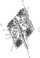
- FIGS. 2 and 3 are a perspective view and an exploded view of an RET system according to some embodiments of the present disclosure.
- FIG. 4 a is a perspective view of the slider linkage 20 ;
- FIG. 4 b is a perspective view of the rail 30 ;
- FIG. 4 c is a perspective view of the bracket 40 ;
- FIG. 4 d is a perspective view of the slide device 50 .
- the RET system 100 may include a drive motor (not shown), a transmission mechanism and phase shifter for an array of radiating elements.
- the RET system 100 may include multiple phase shifters.
- the RET system 100 may include a first phase shifter 61 and a second phase shifter 62 mounted on a base plate 70 , and the two phase shifters may be configured to adjust the phases of the sub-components of the two polarized RF signals.
- Each phase shifter may include a slide device 50 and a phase shift circuit board 51 .
- the slide device 50 is rotatably mounted on the phase shift circuit board 51 by means of a pivot shaft 52 .
- the phase shift circuit board 51 includes an input port, a plurality of output ports, and conductive traces 54 respectively coupled to two of the output ports.
- the slide device 50 is configured to couple the input port to the respective conductive traces 54 and may slide with respect to the conductive traces 54 to change the phase change experienced by the sub-components of the RF signal from the input port to the corresponding output port.
- the transmission mechanism of the RET system 100 may include a control rod 21 and a slider linkage 20 .
- a motor as an actuator may be configured to drive the control rod 21 .
- the driven control rod 21 may drive the slider linkage 20
- the slider linkage 20 drives the slide device 50 to pivot on the phase shift circuit board 51 .
- a rack-gear transmission may be used between the slider linkage 20 and the slide device 50 .
- the slide device 50 may be configured with a sector gear section as a first tooth section 55
- the slider linkage 20 may be configured with a rack section as a second tooth section 22 ; transmission with a more uniform torque may be realized through the meshing transmission between the first tooth section 55 and the second tooth section 22 .
- the slide device 50 may include a slider (not shown because it is on the back side of the slide device 50 ) and a slider support 56 .
- the slider may be configured as a slide circuit board printed with a first coupling part coupled to the input port and a second coupling part coupled to the corresponding conductive traces 54 respectively.
- the slider may be supported, for example, by being snapped on the slider support 56 made of a dielectric material.
- the slider support 56 may be constructed as a plastic member.
- the slider support 56 may be configured with a sector gear section and cooperate with the rack section of the slider linkage 20 . It should be understood that the structure of the slide device 50 may be various, and in some embodiments, the slider itself may be configured with tooth sections.
- the RET system 100 may include a first phase shifter 61 and a second phase shifter 62 mounted on a base plate 70 , wherein the first phase shifter 61 has a first slide device 501 , and the second phase shifter 62 has a second slide device 502 .
- the slider linkage 20 may be provided with second tooth sections 22 on both sides thereof.
- the RET system 100 may further include a rail 30 and a bracket 40 as shown in FIG. 4 c mounted on the base plate 70 for supporting the rail 30 .
- the RET system 100 may include a first bracket 40 and a second bracket 40 spaced apart from the first bracket 40 .
- the rail 30 may be bridged between the two brackets 40 and provide support for the control rod 21 together with the slider linkage 20 .
- the distance between the two brackets 40 or the length of the rail 30 may substantially correspond to the complete stroke of the control rod 21 .
- the control rod 21 does not need to move out of the bracket 40 or at least less outside of the bracket 40 , so that the extra space reserved for the stroke of the control rod 21 shown in FIG. 1 a may be avoided or at least reduced.
- the bracket 40 may be provided with a through slot 42 , wherein the control rod 21 is configured to be able to pass through the through slot 42 and extend into the rail 30 .
- the rail 30 may be configured as two separate work profiles 32 .
- the two work profiles 32 may be inserted into the receiving slot 44 on the bracket 40 and fixed in the receiving slot 44 .
- the control rod 21 together with the slider linkage 20 may extend into the rail 30 formed by the two work profiles 32 and move smoothly along the rail 30 .
- the rail 30 may be configured into any other suitable structure, and the shape and size of the rail 30 may be adaptively changed according to the design of the control rod 21 and/or the slider linkage 20 .
- the rail 30 may also be configured in one piece.
- the reliable and stable support by the rail 30 further improves the stable movement of the control rod 21 and the slider linkage 20 , so that a large fluctuation in the contact pressure between the slide device 50 and the main circuit board due to the unstable movement of the control rod 21 are prevented, thus maintaining the performance of the phase shifter 60 at an acceptable level.
- the slider linkage 20 may be mounted on the control rod 21 as a separate member.
- the slider linkage 20 may be mounted on the control rod 21 in a form-fitting manner.
- the slider linkage 20 has a convex portion 23 as an engaging portion in addition to the tooth sections provided on both sides thereof, and the convex portion 23 may be fitted on the control rod 21 to match the engaging portion thereof, that is, the groove 24 .
- the slider linkage 20 may be provided with a groove, and the control rod 21 may be provided with a convex portion.
- the slider linkage 20 may be mounted on the control rod 21 by any other suitable joining method, for example, by material joining methods such as welding, or by additional fastening means such as rivets or screws.
- the slider linkage 20 may be integrally formed with and configured as part of the control rod 21 .
- FIG. 5 is a perspective view of the RET system 100 ′
- FIG. 6 is an exploded view of the RET system 100 ′
- FIG. 7 a is a perspective view of the first slide linkage 201 of the RET system 100 ′
- FIG. 7 b is a perspective view of the second slide linkage 202 of the RET system 100 ′.
- the RET system 100 ′ may include a plurality of base plates, and each base plate may have at least one phase shifter.
- the RET system 100 ′ may have a first base plate 701 and a second base plate 702 .
- a first phase shifter 61 and a second phase shifter 62 for the two polarized RF signals are mounted on the first base plate 701 .
- the first phase shifter 61 has a first slide device 501 and a first phase shift circuit board 511
- the second phase shifter 62 has a second slide device 502 and a second phase shift circuit board 512 .
- the first base plate 701 and the second base plate 702 may be stacked on top of each other, thereby improving the compact structure of the antenna.
- the first base plate 701 and the second base plate 702 may also lie horizontally to each other.
- the specific structure of the phase shift circuit boards 511 , 512 and the slide device 501 , 502 reference may be made to the content described for FIGS. 2 to 4 d , which will not be repeated here.
- the transmission mechanism of the RET system 100 ′ according to this embodiment will be described in detail.
- the transmission mechanism may include a control rod 21 , a first slide linkage 201 for driving the first slide device 501 and a second slide linkage 202 for driving the second slide device 502 .
- a motor may be used for driving the control rod 21 (typically only one) as a driving device, and the control rod 21 may drive the first slide linkage 201 .
- the first slide linkage 201 further drives the first slide device 501 to pivot on the first phase shift circuit board 511 .
- the first slide linkage 201 may further drive the second slide linkage 202 , so that the second slide linkage 202 further drives the second slide device 502 to pivot on the second phase shift circuit board 512 .
- the rack-gear transmission as already described above may be used between the first slide linkage 201 and the first slide device 501 and/or between the second slide linkage 202 and the second slide device 502 .
- the RET system 100 ′ may further include a first rail 601 and a second rail 602 .
- the control rod 21 and the first slide linkage 201 may move along the first rail 601 , and the first rail 601 is supported on a bracket 40 mounted on the first base plate 701 .
- the second slide linkage 202 may move along the second rail 602 , and the second rail 202 is supported on the bracket 40 mounted on the second base plate 702 .
- the control rod 21 does not need to move out of the bracket 40 or at least less outside the bracket 40 , so that the extra space reserved for the stroke of the control rod 21 shown in FIG. 1 a may be avoided or at least reduced.
- the first slide linkage 201 may be provided with a first convex portion 203 as the first engaging portion, the first convex portion 203 is configured to be engaged with the groove on the control rod 21 , so that they form a reliable first matching structure.
- the first slide linkage 201 may be further provided with a second convex portion 205 as the second engaging portion, and the second convex portion 205 may be embedded into the gap portion on the first base plate 701 to fit in the groove 206 on the second slide linkage 202 , so that they form a reliable second mating structure.
- the first matching structure and the second matching structure enable the control rod 21 to drive the slider linkages 201 and 202 on different base plates 701 and 702 .
- first slide linkage 201 may be mounted on the control rod 21 by any other suitable joining method, for example by material joining method such as welding or by additional fastening means such as rivets or screws.
- second slide linkage 202 may be mounted on the first slide linkage 201 by any other suitable joining method, for example, by material joining methods such as welding, or by additional fastening devices such as rivets or screws.
- first slide linkage 201 and the second slide linkage 202 may be integrally formed with the control rod 21 .
- the transmission mechanism may include a control rod (typically only one), a first slide linkage for driving the slide device of the phase shifter on the first base plate, and a second slide linkage for driving the slide device of the phase shifter on the second base plate.
- the control rod may drive the first slide linkage and the second slide linkage.
- the first slide linkage may be provided with a first engaging portion configured to engage with a first mating engaging portion on the control rod, and the second slide linkage is provided with a second engaging portion configured to engage with the second mating engaging portion on the control rod, thereby achieving reliable transmission.
- the RET system 100 , 100 ′ may drive a plurality of slide linkages 20 through a control rod 21 driven by a motor, the plurality of slide linkages 20 may accordingly drive the associated slide device 50 to perform a synchronized phase shift operation for each phase shifter 60 .
Landscapes
- Engineering & Computer Science (AREA)
- Computer Networks & Wireless Communication (AREA)
- Waveguide Switches, Polarizers, And Phase Shifters (AREA)
- Variable-Direction Aerials And Aerial Arrays (AREA)
Abstract
Description
Claims (17)
Priority Applications (1)
| Application Number | Priority Date | Filing Date | Title |
|---|---|---|---|
| US18/149,869 US20230155287A1 (en) | 2020-07-24 | 2023-01-04 | Phase shifter, remote electrical tilt system and base station antenna |
Applications Claiming Priority (2)
| Application Number | Priority Date | Filing Date | Title |
|---|---|---|---|
| CN202010725727.1 | 2020-07-24 | ||
| CN202010725727.1A CN113972493A (en) | 2020-07-24 | 2020-07-24 | Phase shifter, electric tuning system and base station antenna |
Related Child Applications (1)
| Application Number | Title | Priority Date | Filing Date |
|---|---|---|---|
| US18/149,869 Continuation US20230155287A1 (en) | 2020-07-24 | 2023-01-04 | Phase shifter, remote electrical tilt system and base station antenna |
Publications (2)
| Publication Number | Publication Date |
|---|---|
| US20220029288A1 US20220029288A1 (en) | 2022-01-27 |
| US11552396B2 true US11552396B2 (en) | 2023-01-10 |
Family
ID=79585890
Family Applications (2)
| Application Number | Title | Priority Date | Filing Date |
|---|---|---|---|
| US17/369,221 Active US11552396B2 (en) | 2020-07-24 | 2021-07-07 | Phase shifter, remote electrical tilt system and base station antenna |
| US18/149,869 Pending US20230155287A1 (en) | 2020-07-24 | 2023-01-04 | Phase shifter, remote electrical tilt system and base station antenna |
Family Applications After (1)
| Application Number | Title | Priority Date | Filing Date |
|---|---|---|---|
| US18/149,869 Pending US20230155287A1 (en) | 2020-07-24 | 2023-01-04 | Phase shifter, remote electrical tilt system and base station antenna |
Country Status (2)
| Country | Link |
|---|---|
| US (2) | US11552396B2 (en) |
| CN (1) | CN113972493A (en) |
Cited By (2)
| Publication number | Priority date | Publication date | Assignee | Title |
|---|---|---|---|---|
| US20220231413A1 (en) * | 2019-09-06 | 2022-07-21 | Commscope Technologies Llc | Remote electronic tilt base station antennas and mechanical calibration for such antennas |
| US11742575B2 (en) * | 2018-07-12 | 2023-08-29 | Commscope Technologies Llc | Remote electronic tilt base station antennas having adjustable RET linkages |
Families Citing this family (3)
| Publication number | Priority date | Publication date | Assignee | Title |
|---|---|---|---|---|
| CN116565485A (en) * | 2022-01-28 | 2023-08-08 | 普罗斯通信技术(苏州)有限公司 | Phase shifting assembly |
| CN217182385U (en) * | 2022-05-10 | 2022-08-12 | 罗森伯格技术有限公司 | Phase shifter |
| CN114927840A (en) * | 2022-06-14 | 2022-08-19 | 昆山立讯射频科技有限公司 | Phase shifting device and base station antenna |
Citations (9)
| Publication number | Priority date | Publication date | Assignee | Title |
|---|---|---|---|---|
| US5512914A (en) * | 1992-06-08 | 1996-04-30 | Orion Industries, Inc. | Adjustable beam tilt antenna |
| US6445353B1 (en) * | 2000-10-30 | 2002-09-03 | Weinbrenner, Inc. | Remote controlled actuator and antenna adjustment actuator and electronic control and digital power converter |
| KR100369221B1 (en) * | 1995-03-31 | 2003-04-08 | 마츠다 가부시키가이샤 | Coating method and basecoat paint used therefor |
| WO2018135831A1 (en) * | 2017-01-17 | 2018-07-26 | 주식회사 이엠따블유 | Phase shift module and communication device comprising same |
| WO2018159973A1 (en) * | 2017-02-28 | 2018-09-07 | 주식회사 이엠따블유 | Phase shifter and communication device comprising same |
| WO2019066308A1 (en) * | 2017-09-27 | 2019-04-04 | 삼성전자주식회사 | Antenna device including phase shifter |
| EP3588670A1 (en) * | 2018-06-29 | 2020-01-01 | CommScope Technologies LLC | Base station antennas including wiper phase shifters |
| CN110931980A (en) * | 2019-12-12 | 2020-03-27 | 罗森伯格技术有限公司 | Phase shifter transmission device |
| CN111816958A (en) * | 2020-06-03 | 2020-10-23 | 摩比天线技术(深圳)有限公司 | Phase shifting device and antenna |
-
2020
- 2020-07-24 CN CN202010725727.1A patent/CN113972493A/en active Pending
-
2021
- 2021-07-07 US US17/369,221 patent/US11552396B2/en active Active
-
2023
- 2023-01-04 US US18/149,869 patent/US20230155287A1/en active Pending
Patent Citations (9)
| Publication number | Priority date | Publication date | Assignee | Title |
|---|---|---|---|---|
| US5512914A (en) * | 1992-06-08 | 1996-04-30 | Orion Industries, Inc. | Adjustable beam tilt antenna |
| KR100369221B1 (en) * | 1995-03-31 | 2003-04-08 | 마츠다 가부시키가이샤 | Coating method and basecoat paint used therefor |
| US6445353B1 (en) * | 2000-10-30 | 2002-09-03 | Weinbrenner, Inc. | Remote controlled actuator and antenna adjustment actuator and electronic control and digital power converter |
| WO2018135831A1 (en) * | 2017-01-17 | 2018-07-26 | 주식회사 이엠따블유 | Phase shift module and communication device comprising same |
| WO2018159973A1 (en) * | 2017-02-28 | 2018-09-07 | 주식회사 이엠따블유 | Phase shifter and communication device comprising same |
| WO2019066308A1 (en) * | 2017-09-27 | 2019-04-04 | 삼성전자주식회사 | Antenna device including phase shifter |
| EP3588670A1 (en) * | 2018-06-29 | 2020-01-01 | CommScope Technologies LLC | Base station antennas including wiper phase shifters |
| CN110931980A (en) * | 2019-12-12 | 2020-03-27 | 罗森伯格技术有限公司 | Phase shifter transmission device |
| CN111816958A (en) * | 2020-06-03 | 2020-10-23 | 摩比天线技术(深圳)有限公司 | Phase shifting device and antenna |
Cited By (3)
| Publication number | Priority date | Publication date | Assignee | Title |
|---|---|---|---|---|
| US11742575B2 (en) * | 2018-07-12 | 2023-08-29 | Commscope Technologies Llc | Remote electronic tilt base station antennas having adjustable RET linkages |
| US20220231413A1 (en) * | 2019-09-06 | 2022-07-21 | Commscope Technologies Llc | Remote electronic tilt base station antennas and mechanical calibration for such antennas |
| US11984663B2 (en) * | 2019-09-06 | 2024-05-14 | Commscope Technologies Llc | Remote electronic tilt base station antennas and mechanical calibration for such antennas |
Also Published As
| Publication number | Publication date |
|---|---|
| US20230155287A1 (en) | 2023-05-18 |
| CN113972493A (en) | 2022-01-25 |
| US20220029288A1 (en) | 2022-01-27 |
Similar Documents
| Publication | Publication Date | Title |
|---|---|---|
| US11552396B2 (en) | Phase shifter, remote electrical tilt system and base station antenna | |
| US11984634B2 (en) | Base station antennas having double-sided phase shifters and/or rearwardly extending phase shifters and associated phase shifter assemblies | |
| US11374316B2 (en) | Base station antennas with remote electronic tilt actuators for controlling multiple phase shifters | |
| EP2430700B1 (en) | Multi-line phase shifter for vertical beam tilt-controlled antenna | |
| US7463190B2 (en) | Panel antenna with variable phase shifter | |
| US11081789B2 (en) | Base station antennas including wiper phase shifters | |
| US11616296B2 (en) | Phase shifter assembly having rack-driven wiper supports therein | |
| US20090021437A1 (en) | Center panel movable three-column array antenna for wireless network | |
| US10615488B2 (en) | Linkage mechanism for base station antenna | |
| US11417937B2 (en) | Phase shifter transmission device | |
| EP3879628A1 (en) | Antenna and phase shifter | |
| US11742575B2 (en) | Remote electronic tilt base station antennas having adjustable RET linkages | |
| CN112751163A (en) | Remote electronic tilt base station antenna with adjustable RET rod support | |
| CN201797042U (en) | Integrated electronic downtilt base station antenna | |
| CN109755693B (en) | Phase shift structure, feed network and dual-polarized antenna | |
| CN113270721A (en) | Phase shifter, antenna unit and antenna | |
| US20210242551A1 (en) | Linkage mechanism for phase shifter assembly | |
| US10749250B2 (en) | Multi-layer phase shifter driving device and related remote electronic tilt systems and antennas | |
| CN212810559U (en) | Electric tuning system and base station antenna | |
| US11677141B2 (en) | Base station antenna, feeder component and frame component | |
| CN111490316A (en) | Phase shifter assembly and electrically-controlled base station antenna with same | |
| KR20230133215A (en) | Full analog phase shifter | |
| CN109756259B (en) | Antenna and switching mechanism of working mode thereof | |
| CN117810699A (en) | Base station antenna | |
| US20230127406A1 (en) | Phase shifter assembly and base station antenna |
Legal Events
| Date | Code | Title | Description |
|---|---|---|---|
| FEPP | Fee payment procedure |
Free format text: ENTITY STATUS SET TO UNDISCOUNTED (ORIGINAL EVENT CODE: BIG.); ENTITY STATUS OF PATENT OWNER: LARGE ENTITY |
|
| STPP | Information on status: patent application and granting procedure in general |
Free format text: DOCKETED NEW CASE - READY FOR EXAMINATION |
|
| AS | Assignment |
Owner name: JPMORGAN CHASE BANK, N.A., NEW YORK Free format text: ABL SECURITY AGREEMENT;ASSIGNORS:ARRIS ENTERPRISES LLC;COMMSCOPE TECHNOLOGIES LLC;COMMSCOPE, INC. OF NORTH CAROLINA;REEL/FRAME:058843/0712 Effective date: 20211112 Owner name: JPMORGAN CHASE BANK, N.A., NEW YORK Free format text: TERM LOAN SECURITY AGREEMENT;ASSIGNORS:ARRIS ENTERPRISES LLC;COMMSCOPE TECHNOLOGIES LLC;COMMSCOPE, INC. OF NORTH CAROLINA;REEL/FRAME:058875/0449 Effective date: 20211112 |
|
| AS | Assignment |
Owner name: WILMINGTON TRUST, DELAWARE Free format text: SECURITY INTEREST;ASSIGNORS:ARRIS SOLUTIONS, INC.;ARRIS ENTERPRISES LLC;COMMSCOPE TECHNOLOGIES LLC;AND OTHERS;REEL/FRAME:060752/0001 Effective date: 20211115 |
|
| AS | Assignment |
Owner name: COMMSCOPE TECHNOLOGIES LLC, NORTH CAROLINA Free format text: ASSIGNMENT OF ASSIGNORS INTEREST;ASSIGNORS:WANG, YIDING;TANG, PULIANG;CHEN, CHANGFU;REEL/FRAME:060053/0773 Effective date: 20220517 |
|
| STPP | Information on status: patent application and granting procedure in general |
Free format text: RESPONSE TO NON-FINAL OFFICE ACTION ENTERED AND FORWARDED TO EXAMINER |
|
| STPP | Information on status: patent application and granting procedure in general |
Free format text: NOTICE OF ALLOWANCE MAILED -- APPLICATION RECEIVED IN OFFICE OF PUBLICATIONS |
|
| STPP | Information on status: patent application and granting procedure in general |
Free format text: PUBLICATIONS -- ISSUE FEE PAYMENT VERIFIED |
|
| STCF | Information on status: patent grant |
Free format text: PATENTED CASE |