US11501525B2 - Systems and methods for panoptic image segmentation - Google Patents
Systems and methods for panoptic image segmentation Download PDFInfo
- Publication number
- US11501525B2 US11501525B2 US16/843,026 US202016843026A US11501525B2 US 11501525 B2 US11501525 B2 US 11501525B2 US 202016843026 A US202016843026 A US 202016843026A US 11501525 B2 US11501525 B2 US 11501525B2
- Authority
- US
- United States
- Prior art keywords
- input image
- segmentation
- bounding box
- query
- bounding boxes
- Prior art date
- Legal status (The legal status is an assumption and is not a legal conclusion. Google has not performed a legal analysis and makes no representation as to the accuracy of the status listed.)
- Active, expires
Links
Images


Classifications
-
- G—PHYSICS
- G06—COMPUTING; CALCULATING OR COUNTING
- G06T—IMAGE DATA PROCESSING OR GENERATION, IN GENERAL
- G06T7/00—Image analysis
- G06T7/10—Segmentation; Edge detection
- G06T7/11—Region-based segmentation
-
- G—PHYSICS
- G06—COMPUTING; CALCULATING OR COUNTING
- G06F—ELECTRIC DIGITAL DATA PROCESSING
- G06F18/00—Pattern recognition
- G06F18/20—Analysing
- G06F18/21—Design or setup of recognition systems or techniques; Extraction of features in feature space; Blind source separation
- G06F18/214—Generating training patterns; Bootstrap methods, e.g. bagging or boosting
-
- G—PHYSICS
- G06—COMPUTING; CALCULATING OR COUNTING
- G06F—ELECTRIC DIGITAL DATA PROCESSING
- G06F18/00—Pattern recognition
- G06F18/20—Analysing
- G06F18/23—Clustering techniques
-
- G06K9/6256—
-
- G—PHYSICS
- G06—COMPUTING; CALCULATING OR COUNTING
- G06T—IMAGE DATA PROCESSING OR GENERATION, IN GENERAL
- G06T7/00—Image analysis
- G06T7/10—Segmentation; Edge detection
-
- G—PHYSICS
- G06—COMPUTING; CALCULATING OR COUNTING
- G06V—IMAGE OR VIDEO RECOGNITION OR UNDERSTANDING
- G06V10/00—Arrangements for image or video recognition or understanding
- G06V10/20—Image preprocessing
- G06V10/25—Determination of region of interest [ROI] or a volume of interest [VOI]
-
- G—PHYSICS
- G06—COMPUTING; CALCULATING OR COUNTING
- G06V—IMAGE OR VIDEO RECOGNITION OR UNDERSTANDING
- G06V10/00—Arrangements for image or video recognition or understanding
- G06V10/40—Extraction of image or video features
- G06V10/44—Local feature extraction by analysis of parts of the pattern, e.g. by detecting edges, contours, loops, corners, strokes or intersections; Connectivity analysis, e.g. of connected components
- G06V10/443—Local feature extraction by analysis of parts of the pattern, e.g. by detecting edges, contours, loops, corners, strokes or intersections; Connectivity analysis, e.g. of connected components by matching or filtering
- G06V10/449—Biologically inspired filters, e.g. difference of Gaussians [DoG] or Gabor filters
- G06V10/451—Biologically inspired filters, e.g. difference of Gaussians [DoG] or Gabor filters with interaction between the filter responses, e.g. cortical complex cells
- G06V10/454—Integrating the filters into a hierarchical structure, e.g. convolutional neural networks [CNN]
-
- G—PHYSICS
- G06—COMPUTING; CALCULATING OR COUNTING
- G06V—IMAGE OR VIDEO RECOGNITION OR UNDERSTANDING
- G06V10/00—Arrangements for image or video recognition or understanding
- G06V10/70—Arrangements for image or video recognition or understanding using pattern recognition or machine learning
- G06V10/762—Arrangements for image or video recognition or understanding using pattern recognition or machine learning using clustering, e.g. of similar faces in social networks
-
- G—PHYSICS
- G06—COMPUTING; CALCULATING OR COUNTING
- G06V—IMAGE OR VIDEO RECOGNITION OR UNDERSTANDING
- G06V10/00—Arrangements for image or video recognition or understanding
- G06V10/70—Arrangements for image or video recognition or understanding using pattern recognition or machine learning
- G06V10/82—Arrangements for image or video recognition or understanding using pattern recognition or machine learning using neural networks
-
- G—PHYSICS
- G06—COMPUTING; CALCULATING OR COUNTING
- G06V—IMAGE OR VIDEO RECOGNITION OR UNDERSTANDING
- G06V10/00—Arrangements for image or video recognition or understanding
- G06V10/94—Hardware or software architectures specially adapted for image or video understanding
- G06V10/955—Hardware or software architectures specially adapted for image or video understanding using specific electronic processors
-
- G—PHYSICS
- G06—COMPUTING; CALCULATING OR COUNTING
- G06V—IMAGE OR VIDEO RECOGNITION OR UNDERSTANDING
- G06V20/00—Scenes; Scene-specific elements
- G06V20/10—Terrestrial scenes
-
- G—PHYSICS
- G06—COMPUTING; CALCULATING OR COUNTING
- G06V—IMAGE OR VIDEO RECOGNITION OR UNDERSTANDING
- G06V20/00—Scenes; Scene-specific elements
- G06V20/50—Context or environment of the image
- G06V20/56—Context or environment of the image exterior to a vehicle by using sensors mounted on the vehicle
- G06V20/58—Recognition of moving objects or obstacles, e.g. vehicles or pedestrians; Recognition of traffic objects, e.g. traffic signs, traffic lights or roads
-
- G—PHYSICS
- G06—COMPUTING; CALCULATING OR COUNTING
- G06T—IMAGE DATA PROCESSING OR GENERATION, IN GENERAL
- G06T2207/00—Indexing scheme for image analysis or image enhancement
- G06T2207/20—Special algorithmic details
- G06T2207/20081—Training; Learning
-
- G—PHYSICS
- G06—COMPUTING; CALCULATING OR COUNTING
- G06T—IMAGE DATA PROCESSING OR GENERATION, IN GENERAL
- G06T2207/00—Indexing scheme for image analysis or image enhancement
- G06T2207/20—Special algorithmic details
- G06T2207/20084—Artificial neural networks [ANN]
-
- G—PHYSICS
- G06—COMPUTING; CALCULATING OR COUNTING
- G06T—IMAGE DATA PROCESSING OR GENERATION, IN GENERAL
- G06T2207/00—Indexing scheme for image analysis or image enhancement
- G06T2207/30—Subject of image; Context of image processing
- G06T2207/30248—Vehicle exterior or interior
- G06T2207/30252—Vehicle exterior; Vicinity of vehicle
Definitions
- the subject matter described herein generally relates to robotics and machine vision and, more particularly, to systems and methods for panoptic image segmentation.
- Panoptic segmentation a scene-understanding task that arises in some applications, aims to provide a complete two-dimensional (2D) description of a scene.
- each pixel in an input image is assigned a semantic class (as in semantic segmentation), and each object instance is also identified and segmented (as in instance segmentation).
- the image pixels are sometimes categorized into two high-level classes: “stuff,” representing amorphous and uncountable regions (e.g., sky and roadway), and “things,” representing countable objects such as people and vehicles.
- the system comprises one or more processors and a memory communicably coupled to the one or more processors.
- the memory stores a neural network module including instructions that when executed by the one or more processors cause the one or more processors to perform semantic segmentation and object detection on an input image, wherein the object detection generates a plurality of bounding boxes associated with an object in the input image.
- the memory also stores a fusion module including instructions that when executed by the one or more processors cause the one or more processors to select a query bounding box from among the plurality of bounding boxes.
- the fusion module also includes instructions that when executed by the one or more processors cause the one or more processors to map at least one of the bounding boxes in the plurality of bounding boxes other than the query bounding box to the query bounding box based on similarity between the at least one of the bounding boxes and the query bounding box to generate a mask assignment for the object, the mask assignment defining a contour of the object.
- the fusion module also includes instructions that when executed by the one or more processors cause the one or more processors to compare the mask assignment with results of the semantic segmentation to produce a refined mask assignment for the object.
- the fusion module also includes instructions that when executed by the one or more processors cause the one or more processors to output a panoptic segmentation of the input image that includes the refined mask assignment for the object.
- Another embodiment is a non-transitory computer-readable medium for panoptic image segmentation and storing instructions that when executed by one or more processors cause the one or more processors to perform semantic segmentation and object detection on an input image, wherein the object detection generates a plurality of bounding boxes associated with an object in the input image.
- the instructions also cause the one or more processors to select a query bounding box from among the plurality of bounding boxes.
- the instructions also cause the one or more processors to map at least one of the bounding boxes in the plurality of bounding boxes other than the query bounding box to the query bounding box based on similarity between the at least one of the bounding boxes and the query bounding box to generate a mask assignment for the object, the mask assignment defining a contour of the object.
- the instructions also cause the one or more processors to compare the mask assignment with results of the semantic segmentation to produce a refined mask assignment for the object.
- the instructions also cause the one or more processors to output a panoptic segmentation of the input image that includes the refined mask assignment for the object.
- a method of panoptic image segmentation comprises performing semantic segmentation and object detection on an input image, wherein the object detection generates a plurality of bounding boxes associated with an object in the input image.
- the method also includes selecting a query bounding box from among the plurality of bounding boxes.
- the method also includes mapping at least one of the bounding boxes in the plurality of bounding boxes other than the query bounding box to the query bounding box based on similarity between the at least one of the bounding boxes and the query bounding box to generate a mask assignment for the object, the mask assignment defining a contour of the object.
- the method also includes comparing the mask assignment with results of the semantic segmentation to produce a refined mask assignment for the object.
- the method also includes outputting a panoptic segmentation of the input image that includes the refined mask assignment for the object.
- FIG. 1 illustrates one embodiment of a vehicle within which systems and methods disclosed herein may be implemented.
- FIG. 2 illustrates one embodiment of a panoptic image segmentation system integrated with a vehicle.
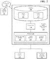
- FIG. 3A is a functional block diagram of a panoptic image segmentation system, in accordance with an illustrative embodiment of the invention.
- FIG. 3B illustrates an input image depicting an object and a plurality of bounding boxes associated with the object, in accordance with an illustrative embodiment of the invention.
- FIG. 4A is an architecture diagram of a neural network for panoptic image segmentation, in accordance with an illustrative embodiment of the invention.
- FIG. 4B is an architecture diagram of a panoptic head of the neural network for panoptic image segmentation shown in FIG. 4A , in accordance with an illustrative embodiment of the invention.
- FIG. 5 is a flowchart of a method of panoptic image segmentation, in accordance with an illustrative embodiment of the invention.
- Various embodiments described herein streamline and improve existing panoptic-image-segmentation frameworks in at least two ways.
- most conventional accurate instance segmentation methods follow a “detect-then-segment” philosophy, but a significant amount of information is discarded during the “detect” (object-detection) phase.
- “dense” object-detection algorithms first generate multiple bounding-box proposals (e.g., one per image pixel) corresponding to a single target object in the scene. Then, Non-Maximum Suppression (NMS) or an equivalent filtering process identifies the bounding-box proposals with the highest level of confidence and ignores the rest.
- NMS Non-Maximum Suppression
- This selection strategy discards the lower-ranking bounding-box proposals generated by the network, even though they might overlap significantly with ground truth.
- Various embodiments described herein improve on conventional approaches by, among other things, reusing the dense bounding-box proposals discarded by a filtering process such as NMS to recover instance masks directly, i.e., without re-sampling features or clustering post-processing.
- semantic segmentation captures much of the same information as object detection.
- class predictions for object detection are a subset of those for semantic segmentation and are produced from identical representations.
- sharing computations across semantic-segmentation and object-detection streams can significantly reduce the overall complexity.
- the embodiments described herein reuse information across these two streams in a single-shot (single-stage) panoptic segmentation framework that achieves real-time inference speeds while maintaining high accuracy.
- the embodiments described herein extend dense object detection and semantic segmentation by reusing discarded object-detection outputs via parameter-free global self-attention and sharing computations between object detection and semantic segmentation in a single-shot framework for real-time panoptic image segmentation that can achieve faster inference than conventional systems without sacrificing accuracy.
- vehicle 100 an example of a vehicle 100 , in which systems and methods disclosed herein can be implemented, is illustrated.
- a vehicle 100 is only one example of an environment in which systems and methods disclosed herein can be implemented.
- the techniques described herein have wide application to other areas of robotics, including humanoid robots.
- the vehicle 100 can include a panoptic image segmentation system 170 or components and/or modules thereof.
- a “vehicle” is any form of motorized transport.
- the vehicle 100 can be an automobile.
- the vehicle 100 may be any other form of motorized transport.
- vehicle 100 is capable of operating in a manual, semi-autonomous, parallel-autonomy, or fully autonomous mode.
- the vehicle 100 can include the panoptic image segmentation system 170 or capabilities to support or interact with the panoptic image segmentation system 170 and thus benefits from the functionality discussed herein. While arrangements will be described herein with respect to automobiles, it will be understood that implementations are not limited to automobiles. Instead, implementations of the principles discussed herein can be applied to any kind of vehicle and to devices and environments (e.g., robots) other than vehicles, as discussed above. Instances of vehicle 100 , as used herein, are equally applicable to any device capable of incorporating the systems or methods described herein.
- the vehicle 100 also includes various elements. It will be understood that, in various implementations, it may not be necessary for the vehicle 100 to have all of the elements shown in FIG. 1 .
- the vehicle 100 can have any combination of the various elements shown in FIG. 1 . Further, the vehicle 100 can have additional elements to those shown in FIG. 1 . In some arrangements, the vehicle 100 may be implemented without one or more of the elements shown in FIG. 1 , including panoptic image segmentation system 170 . While the various elements are shown as being located within the vehicle 100 in FIG. 1 , it will be understood that one or more of these elements can be located external to the vehicle 100 . Further, the elements shown may be physically separated by large distances. As shown in FIG. 1 , vehicle 100 may communicate with one or more other network nodes 180 (cloud servers, infrastructure systems, user mobile devices, etc.) via network 190 .
- network nodes 180 cloud servers, infrastructure systems, user mobile devices, etc.
- FIG. 1 Some of the possible elements of the vehicle 100 are shown in FIG. 1 and will be described in connection with subsequent figures. However, a description of many of the elements in FIG. 1 will be provided after the discussion of FIGS. 2-5 for purposes of brevity of this description. Additionally, it will be appreciated that for simplicity and clarity of illustration, where appropriate, reference numerals have been repeated among the different figures to indicate corresponding or analogous elements. In addition, the discussion outlines numerous specific details to provide a thorough understanding of the embodiments described herein. Those skilled in the art, however, will understand that the embodiments described herein may be practiced using various combinations of these elements.
- Sensor system 120 can include one or more vehicle sensors 121 .
- Vehicle sensors 121 can include one or more positioning systems such as a dead-reckoning system or a global navigation satellite system (GNSS) such as a global positioning system (GPS).
- Vehicle sensors 121 can also include Controller-Area-Network (CAN) sensors that output, for example, speed and steering-angle data pertaining to vehicle 100 .
- Sensor system 120 can also include one or more environment sensors 122 .
- Environment sensors 122 can include radar sensor(s) 123 , Light Detection and Ranging (LIDAR) sensor(s) 124 , sonar sensor(s) 125 , and camera(s) 126 .
- LIDAR Light Detection and Ranging
- image data from camera(s) 126 is of particular relevance because panoptic image segmentation system 170 can perform panoptic segmentation of input images from camera(s) 126 .
- the input images are in red-green-blue (RGB) format. In other embodiments, a different image format may be used.
- panoptic image segmentation system 170 is shown as including one or more processors 110 from the vehicle 100 of FIG. 1 .
- the one or more processors 110 may be a part of panoptic image segmentation system 170
- panoptic image segmentation system 170 may include one or more separate processors from the one or more processors 110 of the vehicle 100
- panoptic image segmentation system 170 may access the one or more processors 110 through a data bus or another communication path, depending on the embodiment.
- memory 210 stores a neural network module 220 , a fusion module 230 , and a training module 240 .
- the memory 210 is a random-access memory (RAM), read-only memory (ROM), a hard-disk drive, a flash memory, or other suitable memory for storing the modules 220 , 230 , and 240 .
- the modules 220 , 230 , and 240 are, for example, computer-readable instructions that when executed by the one or more processors 110 , cause the one or more processors 110 to perform the various functions disclosed herein.
- panoptic image segmentation system 170 can communicate with one or more other network nodes 180 (e.g., cloud servers, infrastructure systems, user mobile devices, etc.) via network 190 .
- network nodes 180 e.g., cloud servers, infrastructure systems, user mobile devices, etc.
- panoptic image segmentation system 170 can employ a technology such as cellular data (LTE, 5G, etc.).
- panoptic image segmentation system 170 can also interface and communicate with sensor system 120 and autonomous driving module(s) 160 , in some embodiments.
- panoptic image segmentation system 170 stores image data 260 output by sensor system 120 (e.g., camera(s) 126 ) or acquired from another source in a database 250 .
- image data 260 can include a collection of sample images as training data for training one or more neural networks.
- panoptic image segmentation system 170 stores, in database 250 , model data 270 (e.g., intermediate calculations, bounding-box proposals, query bounding boxes, mask assignments, figures of merit, etc.) associated with its panoptic-segmentation processes.
- model data 270 e.g., intermediate calculations, bounding-box proposals, query bounding boxes, mask assignments, figures of merit, etc.
- panoptic image segmentation system 170 The remainder of this description is organized as follows. First, an overview is provided of the functions performed by the various modules included in panoptic image segmentation system 170 . Second, certain embodiments of panoptic image segmentation system 170 are described in greater detail, including the underlying mathematical concepts and techniques, in connection with FIGS. 4A, and 4B . Third, the methods associated with various embodiments are discussed via the flowchart of FIG. 5 . Finally, a complete description of FIG. 1 is provided.
- Training module 240 which pertains to a training phase of panoptic image segmentation system 170 , generally includes instructions that when executed by the one or more processors 110 cause the one or more processors 110 to train one or more neural networks that perform object detection and semantic segmentation of an input image.
- the training process is supervised to at least some degree.
- the training process is weakly supervised. This is described in greater detail below in connection with FIGS. 4A and 4B .
- panoptic image segmentation system 170 does not include training module 240 .
- the program code, parameters, and data for one or more trained neural networks can be downloaded to a panoptic image segmentation system 170 in a vehicle 100 or other robot from, e.g., a cloud server (see other network nodes 180 in FIGS. 1 and 2 ).
- Neural network module 220 generally includes instructions that when executed by the one or more processors 110 cause the one or more processors 110 to perform semantic segmentation and object detection on an input image, the object-detection process generating a plurality of bounding boxes associated with an object in the input image.
- neural network module 220 produces a bounding-box proposal (herein sometimes referred to simply as a “bounding box”) for each image pixel.
- bounding box a bounding-box proposal
- an object including a plurality of pixels will have a plurality of bounding boxes associated with it.
- each bounding box associated with the object has an associated confidence level.
- neural network module 220 performs object detection and semantic segmentation in parallel or substantially in parallel, and panoptic image segmentation system 170 operates in real time with respect to the frame rate of an imaging system (e.g., camera(s) 126 , in a vehicular embodiment) that produces the input image.
- the instructions in the neural network module 220 to perform semantic segmentation and object detection include instructions to perform semantic segmentation and object detection using a convolutional neural network (CNN).
- CNN convolutional neural network
- Fusion module 230 generally includes instructions that when executed by the one or more processors 110 cause the one or more processors 110 to select a query bounding box from among the plurality of bounding boxes associated with the object. In some embodiments, this is accomplished using a NMS algorithm. In other embodiments, a different filtering algorithm can be used. In one embodiment, the query bounding box is the bounding box among the plurality of bounding boxes associated with the object that has the highest confidence level. This is discussed in greater detail below.
- Fusion module 230 also includes instructions to map at least one of the bounding boxes in the plurality of bounding boxes other than the query bounding box to the query bounding box based on similarity between the at least one of the bounding boxes and the query bounding box to generate a mask assignment (also referred to herein as an “instance mask”) for the object.
- the mask assignment defines the contour (outline shape) of the object.
- the similarity between a given bounding box and the query bounding box is quantified as the relative ratio of overlapping area between the bounding box in question and the query bounding box.
- Fusion module 230 also includes instructions to compare the resulting mask assignment for the object with the results of the semantic segmentation performed by neural network module 220 to produce a refined mask assignment for the object. This may be considered a “clean-up” operation (e.g., differentiating between pixels associated with the object and pixels associated with a background “stuff” class such as “sky” or “roadway”) prior to outputting the final panoptic segmentation of the input image.
- This may be considered a “clean-up” operation (e.g., differentiating between pixels associated with the object and pixels associated with a background “stuff” class such as “sky” or “roadway”) prior to outputting the final panoptic segmentation of the input image.
- Fusion module 230 also includes instructions to output a panoptic segmentation of the input image that includes the refined mask assignment for the object. As discussed further below, this is accomplished through a merging or fusion operation by fusion module 230 .
- the output panoptic segmentation of the input image includes, for each pixel in the input image, a semantic class identifier and an instance identifier. For example, pixels associated with a countable object such as a vehicle might have a semantic class identifier “vehicle” (an example of a “thing” class) and an instance identifier of “3,” if that vehicle is labeled as the third vehicle among a plurality of identified vehicles in the input image. For pixels assigned to “stuff” classes, the instance identifier is set to zero, in some embodiments.
- the same functions for producing a panoptic segmentation of the input image can be performed for each of a plurality of objects in the input image, where the input image includes multiple objects.
- the techniques described above can be generalized to an input image that includes a plurality of objects.
- FIG. 3A is a functional block diagram of a panoptic image segmentation system 170 , in accordance with an illustrative embodiment of the invention.
- FIG. 3A summarizes the functions performed by neural network module 220 and fusion module 230 described above.
- an input image 310 is input to semantic segmentation and object detection processes 320 , which are performed by neural network module 220 .
- these operations are performed in parallel or substantially in parallel by a CNN, and panoptic image segmentation system 170 operates in real time with respect to the frame rate of an imaging system that produces the input images 310 .
- neural network module 220 in connection with performing object detection, generates a plurality of bounding boxes associated with each of one or more objects in input image 310 .
- FIG. 3B illustrates an input image 310 depicting an object 385 (in this example, a vehicle) and a bounding box 390 associated with the object 385 , in accordance with an illustrative embodiment of the invention.
- object 385 in this example, a vehicle
- bounding box 390 associated with the object 385
- FIG. 3B illustrates only one bounding box 390 is shown for clarity.
- object 385 Upon completion of object detection by neural network module 220 , object 385 would have a plurality of associated bounding boxes (e.g., one for each pixel that belongs to object 385 ), as discussed above. This technique may be termed “dense object detection.”
- Filtering process 330 selects a query bounding box from among the plurality of bounding boxes associated with each detected object in the input image to produce query bounding boxes 340 .
- a process of dense bounding box querying 350 maps one or more bounding boxes other than the query bounding box to the query bounding box 340 based on similarity to generate a mask assignment for the object (see mask assignments 360 in FIG. 3A ).
- the similarity between a given bounding box and the query bounding box is quantified as the relative ratio of overlapping area between the bounding box in question and the query bounding box.
- Fusion module 230 performs mask refinement 370 by comparing the resulting mask assignments for the objects with the results of semantic segmentation produced by neural network module 220 to produce a refined set of mask assignments for the respective objects. Upon completion of a merging or fusion operation (not shown in FIG. 3A ), fusion module 230 outputs a panoptic segmentation 380 of the input image 310 . Certain embodiments of panoptic image segmentation system 170 are next described in greater detail, including the mathematical concepts and techniques.
- panoptic segmentation task that involves solving a semantic segmentation task ( ) and a dense-bounding-box object-detection task ( ).
- CNN convolutional neural network
- the bounding-box proposal set is denoted query because it is used, in a sense, to “search” for instance masks.
- fusion module 230 performs a fusion (merging) process.
- FIG. 4A is an architecture diagram of a neural network 400 for panoptic image segmentation, in accordance with an illustrative embodiment of the invention.
- This architecture is built on a ResNet-50 Feature Pyramid Network (FPN) (ResNet-50-FPN 405 ) backbone.
- ResNet-50-FPN 405 includes five levels corresponding to strides of 128 , 64 , 32 , 16 , and 8 with respect to the input image.
- FPN ResNet-50 Feature Pyramid Network
- ResNet-50-FPN 405 includes five levels corresponding to strides of 128 , 64 , 32 , 16 , and 8 with respect to the input image.
- These embodiments also include a finer-grained target assignment scheme and additional single-convolution layers for semantic segmentation and a “levelness” prediction for object detection, which is described further below.
- the illustrated framework also leverages the fully tensorizable mask-construction algorithm described above, and these embodiments include an explicit instance-mask loss that further improves the quality of the final panoptic segmentation.
- the output of ResNet-50-FPN 405 is input to a set of panoptic heads 410 , whose outputs are fed to object-detection (levelness) elements 415 and semantic-segmentation elements 420 .
- object-detection (levelness) elements 415 and semantic-segmentation elements 420 Some of the details of the structure of object detection elements 415 and semantic segmentation elements 420 are indicated in FIG. 4A .
- FIG. 4B is an architecture diagram of a panoptic head 410 of the neural network 400 for panoptic image segmentation shown in FIG. 4A , in accordance with an illustrative embodiment of the invention.
- These embodiments include a unified panoptic head that is shared by each of the multi-scale feature maps produced by the backbone (ResNet-50-FPN 405 , in FIG. 4A ).
- On each feature map two feature towers, localization tower 425 and semantics tower 430 , are applied.
- Each tower includes four sequential convolutional blocks (Conv+GroupNorm+ReLU).
- panoptic head 410 uses the extracted features to predict bounding-box offsets ⁇ circumflex over (t) ⁇ xy , centerness ô xy , and bounding-box class probabilities ⁇ xy .
- the bounding-box offset is predicted from the localization tower 425
- the bounding-box class probability distribution is predicted from the semantics tower 430 .
- panoptic head 410 employs an intersection-over union (IoU) loss as follows:
- panoptic head 410 predicts a probability distribution over object classes ⁇ xy ⁇ N things for all feature locations (x, y), including background pixels.
- the bounding-box classification loss box_cls is a standard sigmoid focal loss averaged over the total number of locations across all FPN levels.
- Panoptic head 410 leverages the intermediate features from the two towers (F loc i and F sem i ) to globally predict (1) Levelness : the FPN level that the bounding box at each location (x, y) belongs to (with zero reserved for background pixels); and (2) Semantic segmentation : the semantic class probability distribution over N classes.
- Levelness the FPN level that the bounding box at each location (x, y) belongs to (with zero reserved for background pixels); and
- Semantic segmentation the semantic class probability distribution over N classes.
- F loc i and F sem i are upsampled to an intermediate size of (H/4, W/4) and concatenated into a global F loc and F sem .
- the levelness is predicted from F loc through a single convolutional layer and is supervised by a FPN level assignment policy.
- levelness L CE ( , t )
- neural network 400 produces a bounding-box prediction ⁇ circumflex over (b) ⁇ xy (i) from each FPN level F i .
- neural network 400 Instead of using a separate branch for semantic segmentation, neural network 400 reuses the same features as bounding-box classification. This dramatically reduces the number of parameters and inference time of neural network 400 .
- FIG. 5 is a flowchart of a method 500 of panoptic image segmentation, in accordance with an illustrative embodiment of the invention.
- Method 500 will be discussed from the perspective of panoptic image segmentation system 170 in FIG. 2 . While method 500 is discussed in combination with panoptic image segmentation system 170 , it should be appreciated that method 500 is not limited to being implemented within panoptic image segmentation system 170 , but panoptic image segmentation system 170 is instead one example of a system that may implement method 500 .
- neural network module 220 performs semantic segmentation and object detection on an input image 310 .
- the input image 310 is in red-green-blue (RGB) format.
- RGB red-green-blue
- object detection generates a plurality of bounding boxes associated with an object in the input image.
- neural network module 220 produces a bounding box for each pixel.
- an object including a plurality of pixels will have a plurality of bounding boxes associated with it.
- each bounding box associated with the object has an associated confidence level.
- the semantic segmentation and object detection are performed in parallel or substantially in parallel by a neural network 400 (e.g., a CNN) associated with neural network module 220 , and panoptic image segmentation system 170 operates in real time with respect to the frame rate of an imaging system that produces the input image 310 .
- a neural network 400 e.g., a CNN
- panoptic image segmentation system 170 operates in real time with respect to the frame rate of an imaging system that produces the input image 310 .
- fusion module 230 selects a query bounding box 340 from among the plurality of bounding boxes. As discussed above, in some embodiments, this is accomplished using a NMS algorithm. In other embodiments, a different filtering algorithm can be used. In one embodiment, the query bounding box is the bounding box among the plurality of bounding boxes that has the highest confidence level.
- fusion module 230 map at least one of the bounding boxes in the plurality of bounding boxes other than the query bounding box to the query bounding box based on similarity between the at least one of the bounding boxes and the query bounding box to generate a mask assignment (instance mask) for the object, the mask assignment defining the contour (outline shape) of the object.
- the similarity between a given bounding box and the query bounding box is quantified as the relative ratio of overlapping area between the bounding box in question and the query bounding box.
- fusion module 230 compares the mask assignment with results of the semantic segmentation performed by neural network module 220 to produce a refined mask assignment for the object. As discussed above, this may be thought of as a “clean-up” operation (e.g., differentiating between pixels associated with the object and pixels associated with a background “stuff” class such as “sky” or “roadway”).
- fusion module 230 outputs a panoptic segmentation 380 of the input image 310 that includes the refined mask assignment 360 for the object. As discussed above, this is accomplished through a merging operation by fusion module 230 .
- the output panoptic segmentation of the input image includes, for each pixel in the input image, a semantic class identifier and an instance identifier. For example, pixels associated with a countable object such as a vehicle might have a semantic class identifier “vehicle” (an example of a “thing” class) and an instance identifier of “3,” if that vehicle is labeled as the third vehicle among a plurality of identified vehicles in the input image. For pixels assigned to “stuff” classes, the instance identifier can be set to zero, in some embodiments.
- method 500 focuses on a particular detected object in the input image 310 , the same functions leading ultimately to a panoptic segmentation 380 of the input image 310 can be performed for each of a plurality of objects in the input image 310 , where the input image includes multiple objects.
- panoptic image segmentation system 170 is integrated with a vehicle.
- the vehicle is an autonomous vehicle.
- Panoptic image segmentation system 170 may also be integrated with a variety of other kinds of robots, including humanoid robots.
- FIG. 1 will now be discussed in full detail as an example vehicle environment within which the systems and methods disclosed herein may be implemented.
- the vehicle 100 can be configured to switch selectively between an autonomous mode, one or more semi-autonomous operational modes, and/or a manual mode. Such switching, also referred to as handover when transitioning to a manual mode, can be implemented in a suitable manner, now known or later developed.
- “Manual mode” means that all of or a majority of the navigation and/or maneuvering of the vehicle is performed according to inputs received from a user (e.g., human driver/operator).
- the vehicle 100 can be an autonomous vehicle.
- autonomous vehicle refers to a vehicle that operates in an autonomous mode.
- Autonomous mode refers to navigating and/or maneuvering a vehicle along a travel route using one or more computing devices to control the vehicle with minimal or no input from a human driver/operator.
- the vehicle 100 is configured with one or more semi-autonomous operational modes in which one or more computing devices perform a portion of the navigation and/or maneuvering of the vehicle along a travel route, and a vehicle operator (i.e., driver) provides inputs to the vehicle to perform a portion of the navigation and/or maneuvering of the vehicle 100 along a travel route.
- the vehicle 100 operates autonomously according to a particular defined level of autonomy.
- the vehicle 100 can include one or more processors 110 .
- the one or more processors 110 can be a main processor of the vehicle 100 .
- the one or more processors 110 can be an electronic control unit (ECU).
- the vehicle 100 can include one or more data stores 115 for storing one or more types of data.
- the data store(s) 115 can include volatile and/or non-volatile memory. Examples of suitable data stores 115 include RAM, flash memory, ROM, PROM (Programmable Read-Only Memory), EPROM, EEPROM (Electrically Erasable Programmable Read-Only Memory), registers, magnetic disks, optical disks, hard drives, or any other suitable storage medium, or any combination thereof.
- the data store(s) 115 can be a component(s) of the one or more processors 110 , or the data store(s) 115 can be operatively connected to the one or more processors 110 for use thereby.
- the term “operatively connected,” as used throughout this description, can include direct or indirect connections, including connections without direct physical contact.
- the one or more data stores 115 can include map data 116 .
- the map data 116 can include maps of one or more geographic areas. In some instances, the map data 116 can include information or data on roads, traffic control devices, road markings, structures, features, and/or landmarks in the one or more geographic areas.
- the map data 116 can include one or more terrain maps 117 .
- the terrain map(s) 117 can include information about the ground, terrain, roads, surfaces, and/or other features of one or more geographic areas.
- the map data 116 can include one or more static obstacle maps 118 .
- the static obstacle map(s) 118 can include information about one or more static obstacles located within one or more geographic areas.
- the one or more data stores 115 can include sensor data 119 .
- sensor data means any information about the sensors that a vehicle is equipped with, including the capabilities and other information about such sensors.
- the vehicle 100 can include the sensor system 120 .
- the sensor data 119 can relate to one or more sensors of the sensor system 120 .
- the sensor data 119 can include information on one or more LIDAR sensors 124 of the sensor system 120 .
- vehicle 100 can receive sensor data from other connected vehicles, from devices associated with ORUs, or both.
- the vehicle 100 can include the sensor system 120 .
- the sensor system 120 can include one or more sensors.
- Sensor means any device, component and/or system that can detect, and/or sense something.
- the one or more sensors can be configured to detect, and/or sense in real-time.
- real-time means a level of processing responsiveness that a user or system senses as sufficiently immediate for a particular process or determination to be made, or that enables the processor to keep up with some external process.
- the sensors can function independently from each other.
- two or more of the sensors can work in combination with each other.
- the two or more sensors can form a sensor network.
- the sensor system 120 and/or the one or more sensors can be operatively connected to the one or more processors 110 , the data store(s) 115 , and/or another element of the vehicle 100 (including any of the elements shown in FIG. 1 ).
- the sensor system 120 can include any suitable type of sensor. Various examples of different types of sensors will be described herein. However, it will be understood that the implementations are not limited to the particular sensors described.
- the sensor system 120 can include one or more vehicle sensors 121 .
- the vehicle sensors 121 can detect, determine, and/or sense information about the vehicle 100 itself, including the operational status of various vehicle components and systems.
- the vehicle sensors 121 can be configured to detect, and/or sense position and/orientation changes of the vehicle 100 , such as, for example, based on inertial acceleration.
- the vehicle sensors 121 can include one or more accelerometers, one or more gyroscopes, an inertial measurement unit (IMU), a dead-reckoning system, a global navigation satellite system (GNSS), a global positioning system (GPS), a navigation system 147 , and/or other suitable sensors.
- the vehicle sensors 121 can be configured to detect, and/or sense one or more characteristics of the vehicle 100 .
- the vehicle sensors 121 can include a speedometer to determine a current speed of the vehicle 100 .
- the sensor system 120 can include one or more environment sensors 122 configured to acquire, and/or sense driving environment data.
- Driving environment data includes any data or information about the external environment in which a vehicle is located or one or more portions thereof.
- the one or more environment sensors 122 can be configured to detect, quantify, and/or sense obstacles in at least a portion of the external environment of the vehicle 100 and/or information/data about such obstacles.
- the one or more environment sensors 122 can be configured to detect, measure, quantify, and/or sense other things in at least a portion the external environment of the vehicle 100 , such as, for example, nearby vehicles, lane markers, signs, traffic lights, traffic signs, lane lines, crosswalks, curbs proximate the vehicle 100 , off-road objects, etc.
- the example sensors may be part of the one or more environment sensors 122 and/or the one or more vehicle sensors 121 .
- the sensor system 120 can include operator sensors that function to track or otherwise monitor aspects related to the driver/operator of the vehicle 100 .
- the implementations are not limited to the particular sensors described.
- the sensor system 120 can include one or more radar sensors 123 , one or more LIDAR sensors 124 , one or more sonar sensors 125 , and/or one or more cameras 126 .
- the vehicle 100 can further include a communication system 130 .
- the communication system 130 can include one or more components configured to facilitate communication between the vehicle 100 and one or more communication sources.
- Communication sources refers to people or devices with which the vehicle 100 can communicate with, such as external networks, computing devices, operator or occupants of the vehicle 100 , or others.
- the vehicle 100 can include an input system 131 .
- An “input system” includes any device, component, system, element or arrangement or groups thereof that enable information/data to be entered into a machine.
- the input system 131 can receive an input from a vehicle occupant (e.g., a driver or a passenger).
- the vehicle 100 can include an output system 132 .
- An “output system” includes any device, component, or arrangement or groups thereof that enable information/data to be presented to the one or more communication sources (e.g., a person, a vehicle passenger, etc.).
- the communication system 130 can further include specific elements which are part of or can interact with the input system 131 or the output system 132 , such as one or more display device(s) 133 , and one or more audio device(s) 134 (e.g., speakers and microphones).
- the vehicle 100 can include one or more vehicle systems 140 .
- Various examples of the one or more vehicle systems 140 are shown in FIG. 1 .
- the vehicle 100 can include more, fewer, or different vehicle systems. It should be appreciated that although particular vehicle systems are separately defined, each or any of the systems or portions thereof may be otherwise combined or segregated via hardware and/or software within the vehicle 100 .
- the vehicle 100 can include a propulsion system 141 , a braking system 142 , a steering system 143 , throttle system 144 , a transmission system 145 , a signaling system 146 , and/or a navigation system 147 .
- Each of these systems can include one or more devices, components, and/or combinations thereof, now known or later developed.
- the one or more processors 110 and/or the autonomous driving module(s) 160 can be operatively connected to communicate with the various vehicle systems 140 and/or individual components thereof. For example, returning to FIG. 1 , the one or more processors 110 and/or the autonomous driving module(s) 160 can be in communication to send and/or receive information from the various vehicle systems 140 to control the movement, speed, maneuvering, heading, direction, etc. of the vehicle 100 .
- the one or more processors 110 and/or the autonomous driving module(s) 160 may control some or all of these vehicle systems 140 and, thus, may be partially or fully autonomous.
- the vehicle 100 can include one or more modules, at least some of which are described herein.
- the modules can be implemented as computer-readable program code that, when executed by a processor 110 , implement one or more of the various processes described herein.
- the processor 110 can be a device, such as a CPU, which is capable of receiving and executing one or more threads of instructions for the purpose of performing a task.
- One or more of the modules can be a component of the one or more processors 110 , or one or more of the modules can be executed on and/or distributed among other processing systems to which the one or more processors 110 is operatively connected.
- the modules can include instructions (e.g., program logic) executable by one or more processors 110 .
- one or more data store 115 may contain such instructions.
- one or more of the modules described herein can include artificial or computational intelligence elements, e.g., neural network, fuzzy logic or other machine learning algorithms. Further, in one or more arrangements, one or more of the modules can be distributed among a plurality of the modules described herein. In one or more arrangements, two or more of the modules described herein can be combined into a single module.
- artificial or computational intelligence elements e.g., neural network, fuzzy logic or other machine learning algorithms.
- one or more of the modules can be distributed among a plurality of the modules described herein. In one or more arrangements, two or more of the modules described herein can be combined into a single module.
- the vehicle 100 can include one or more autonomous driving modules 160 .
- the autonomous driving module(s) 160 can be configured to receive data from the sensor system 120 and/or any other type of system capable of capturing information relating to the vehicle 100 and/or the external environment of the vehicle 100 . In one or more arrangements, the autonomous driving module(s) 160 can use such data to generate one or more driving scene models.
- the autonomous driving module(s) 160 can determine the position and velocity of the vehicle 100 .
- the autonomous driving module(s) 160 can determine the location of obstacles, or other environmental features including traffic signs, trees, shrubs, neighboring vehicles, pedestrians, etc.
- the autonomous driving module(s) 160 can be configured to determine travel path(s), current autonomous driving maneuvers for the vehicle 100 , future autonomous driving maneuvers and/or modifications to current autonomous driving maneuvers based on data acquired by the sensor system 120 , driving scene models, and/or data from any other suitable source.
- Driving maneuver means one or more actions that affect the movement of a vehicle. Examples of driving maneuvers include: accelerating, decelerating, braking, turning, moving in a lateral direction of the vehicle 100 , changing travel lanes, merging into a travel lane, and/or reversing, just to name a few possibilities.
- the autonomous driving module(s) 160 can be configured can be configured to implement determined driving maneuvers.
- the autonomous driving module(s) 160 can cause, directly or indirectly, such autonomous driving maneuvers to be implemented.
- “cause” or “causing” means to make, command, instruct, and/or enable an event or action to occur or at least be in a state where such event or action may occur, either in a direct or indirect manner.
- the autonomous driving module(s) 160 can be configured to execute various vehicle functions and/or to transmit data to, receive data from, interact with, and/or control the vehicle 100 or one or more systems thereof (e.g., one or more of vehicle systems 140 ). The noted functions and methods will become more apparent with a further discussion of the figures.
- each block in the flowcharts or block diagrams can represent a module, segment, or portion of code, which comprises one or more executable instructions for implementing the specified logical function(s).
- the functions noted in the block can occur out of the order noted in the figures. For example, two blocks shown in succession can be executed substantially concurrently, or the blocks can sometimes be executed in the reverse order, depending upon the functionality involved.
- the systems, components and/or methods described above can be realized in hardware or a combination of hardware and software and can be realized in a centralized fashion in one processing system or in a distributed fashion where different elements are spread across several interconnected processing systems. Any kind of processing system or other apparatus adapted for carrying out the methods described herein is suited.
- a typical combination of hardware and software can be a processing system with computer-usable program code that, when being loaded and executed, controls the processing system such that it carries out the methods described herein.
- the systems, components and/or methods also can be embedded in a computer-readable storage, such as a computer program product or other data programs storage device, readable by a machine, tangibly embodying a program of instructions executable by the machine to perform methods and methods described herein. These elements also can be embedded in an application product which comprises all the features enabling the implementation of the methods described herein and, which when loaded in a processing system, is able to carry out these methods.
- arrangements described herein can take the form of a computer program product embodied in one or more computer-readable media having computer-readable program code embodied or embedded, such as stored thereon. Any combination of one or more computer-readable media can be utilized.
- the computer-readable medium can be a computer-readable signal medium or a computer-readable storage medium.
- the phrase “computer-readable storage medium” means a non-transitory storage medium.
- a computer-readable storage medium can be, for example, but not limited to, an electronic, magnetic, optical, electromagnetic, infrared, or semiconductor system, apparatus, or device, or any suitable combination of the foregoing.
- a computer-readable storage medium can be any tangible medium that can contain, or store a program for use by, or in connection with, an instruction execution system, apparatus, or device.
- Program code embodied on a computer-readable medium can be transmitted using any appropriate medium, including but not limited to wireless, wireline, optical fiber, cable, RF, etc., or any suitable combination of the foregoing.
- Computer program code for carrying out operations for aspects of the present arrangements can be written in any combination of one or more programming languages, including an object-oriented programming language such as JavaTM, Smalltalk, C++ or the like and conventional procedural programming languages, such as the “C” programming language or similar programming languages.
- the program code can execute entirely on the user's computer, partly on the user's computer, as a stand-alone software package, partly on the user's computer and partly on a remote computer, or entirely on the remote computer or server.
- the remote computer can be connected to the user's computer through any type of network, including a LAN or a WAN, or the connection can be made to an external computer (for example, through the Internet using an Internet Service Provider).
- module includes routines, programs, objects, components, data structures, and so on that perform particular tasks or implement particular data types.
- a memory generally stores the noted modules.
- the memory associated with a module may be a buffer or cache embedded within a processor, a RAM, a ROM, a flash memory, or another suitable electronic storage medium.
- a module as envisioned by the present disclosure is implemented as an application-specific integrated circuit (ASIC), a hardware component of a system on a chip (SoC), as a programmable logic array (PLA), or as another suitable hardware component that is embedded with a defined configuration set (e.g., instructions) for performing the disclosed functions.
- ASIC application-specific integrated circuit
- SoC system on a chip
- PLA programmable logic array
- the terms “a” and “an,” as used herein, are defined as one as or more than one.
- the term “plurality,” as used herein, is defined as two or more than two.
- the term “another,” as used herein, is defined as at least a second or more.
- the terms “including” and/or “having,” as used herein, are defined as including (i.e., open language).
- the phrase “at least one of . . . and . . . ” as used herein refers to and encompasses any and all possible combinations of one or more of the associated listed items.
- the phrase “at least one of A, B and C” includes A only, B only, C only, or any combination thereof (e.g., AB, AC, BC or ABC).
Abstract
Description
Finally,
Claims (17)
Priority Applications (1)
| Application Number | Priority Date | Filing Date | Title |
|---|---|---|---|
| US16/843,026 US11501525B2 (en) | 2019-11-26 | 2020-04-08 | Systems and methods for panoptic image segmentation |
Applications Claiming Priority (2)
| Application Number | Priority Date | Filing Date | Title |
|---|---|---|---|
| US201962940517P | 2019-11-26 | 2019-11-26 | |
| US16/843,026 US11501525B2 (en) | 2019-11-26 | 2020-04-08 | Systems and methods for panoptic image segmentation |
Publications (2)
| Publication Number | Publication Date |
|---|---|
| US20210158043A1 US20210158043A1 (en) | 2021-05-27 |
| US11501525B2 true US11501525B2 (en) | 2022-11-15 |
Family
ID=75975416
Family Applications (1)
| Application Number | Title | Priority Date | Filing Date |
|---|---|---|---|
| US16/843,026 Active 2041-03-12 US11501525B2 (en) | 2019-11-26 | 2020-04-08 | Systems and methods for panoptic image segmentation |
Country Status (1)
| Country | Link |
|---|---|
| US (1) | US11501525B2 (en) |
Families Citing this family (15)
| Publication number | Priority date | Publication date | Assignee | Title |
|---|---|---|---|---|
| US11430238B1 (en) * | 2019-06-26 | 2022-08-30 | Apple Inc. | Generating a contextual information vector for improved scene understanding |
| US11481862B2 (en) * | 2020-02-26 | 2022-10-25 | Beijing Jingdong Shangke Information Technology Co., Ltd. | System and method for real-time, simultaneous object detection and semantic segmentation |
| US11256960B2 (en) * | 2020-04-15 | 2022-02-22 | Adobe Inc. | Panoptic segmentation |
| US11640714B2 (en) | 2020-04-20 | 2023-05-02 | Adobe Inc. | Video panoptic segmentation |
| US11869125B2 (en) * | 2020-09-30 | 2024-01-09 | Adobe Inc. | Generating composite images with objects from different times |
| EP4009635A1 (en) * | 2020-12-07 | 2022-06-08 | Axis AB | Method and system for producing streams of image frames |
| US11803971B2 (en) * | 2021-05-13 | 2023-10-31 | Adobe Inc. | Generating improved panoptic segmented digital images based on panoptic segmentation neural networks that utilize exemplar unknown object classes |
| US11798289B2 (en) | 2021-05-28 | 2023-10-24 | Motional Ad Llc | Streaming object detection and segmentation with polar pillars |
| US20220371606A1 (en) * | 2021-05-21 | 2022-11-24 | Motional Ad Llc | Streaming object detection and segmentation with polar pillars |
| US20230104262A1 (en) * | 2021-10-06 | 2023-04-06 | Adobe Inc. | Panoptic segmentation refinement network |
| US20230141734A1 (en) * | 2021-11-05 | 2023-05-11 | Adobe Inc. | Digital image inpainting utilizing plane panoptic segmentation and plane grouping |
| US11941884B2 (en) * | 2021-11-12 | 2024-03-26 | Adobe Inc. | Multi-source panoptic feature pyramid network |
| WO2023220677A1 (en) * | 2022-05-11 | 2023-11-16 | Deepnorth Inc. | Self-checkout verification systems and methods |
| CN115661821B (en) * | 2022-12-22 | 2023-04-11 | 摩尔线程智能科技(北京)有限责任公司 | Loop detection method, loop detection device, electronic apparatus, storage medium, and program product |
| CN115908442B (en) * | 2023-01-06 | 2023-05-12 | 山东巍然智能科技有限公司 | Image panorama segmentation method and model building method for unmanned aerial vehicle ocean monitoring |
Citations (8)
| Publication number | Priority date | Publication date | Assignee | Title |
|---|---|---|---|---|
| US20020136449A1 (en) * | 2001-01-20 | 2002-09-26 | Samsung Electronics Co., Ltd. | Apparatus and method for extracting object based on feature matching between segmented regions in images |
| US20190244060A1 (en) | 2018-02-02 | 2019-08-08 | Nvidia Corporation | Domain Stylization Using a Neural Network Model |
| US10424064B2 (en) * | 2016-10-18 | 2019-09-24 | Adobe Inc. | Instance-level semantic segmentation system |
| US20190332625A1 (en) * | 2018-04-26 | 2019-10-31 | Electronics And Telecommunications Research Institute | Apparatus and method for searching for building based on image and method of constructing building search database for image-based building search |
| US20200082219A1 (en) * | 2018-09-07 | 2020-03-12 | Toyota Research Institute, Inc. | Fusing predictions for end-to-end panoptic segmentation |
| US20210027471A1 (en) * | 2019-07-22 | 2021-01-28 | Adobe Inc. | Utilizing object attribute detection models to automatically select instances of detected objects in images |
| US20210263962A1 (en) * | 2020-02-25 | 2021-08-26 | Adobe Inc. | Utilizing natural language processing and multiple object detection models to automatically select objects in images |
| US11256960B2 (en) * | 2020-04-15 | 2022-02-22 | Adobe Inc. | Panoptic segmentation |
-
2020
- 2020-04-08 US US16/843,026 patent/US11501525B2/en active Active
Patent Citations (11)
| Publication number | Priority date | Publication date | Assignee | Title |
|---|---|---|---|---|
| US20020136449A1 (en) * | 2001-01-20 | 2002-09-26 | Samsung Electronics Co., Ltd. | Apparatus and method for extracting object based on feature matching between segmented regions in images |
| US10424064B2 (en) * | 2016-10-18 | 2019-09-24 | Adobe Inc. | Instance-level semantic segmentation system |
| US20190244060A1 (en) | 2018-02-02 | 2019-08-08 | Nvidia Corporation | Domain Stylization Using a Neural Network Model |
| US10984286B2 (en) * | 2018-02-02 | 2021-04-20 | Nvidia Corporation | Domain stylization using a neural network model |
| US20190332625A1 (en) * | 2018-04-26 | 2019-10-31 | Electronics And Telecommunications Research Institute | Apparatus and method for searching for building based on image and method of constructing building search database for image-based building search |
| US20200082219A1 (en) * | 2018-09-07 | 2020-03-12 | Toyota Research Institute, Inc. | Fusing predictions for end-to-end panoptic segmentation |
| US10796201B2 (en) * | 2018-09-07 | 2020-10-06 | Toyota Research Institute, Inc. | Fusing predictions for end-to-end panoptic segmentation |
| US20210027471A1 (en) * | 2019-07-22 | 2021-01-28 | Adobe Inc. | Utilizing object attribute detection models to automatically select instances of detected objects in images |
| US11107219B2 (en) * | 2019-07-22 | 2021-08-31 | Adobe Inc. | Utilizing object attribute detection models to automatically select instances of detected objects in images |
| US20210263962A1 (en) * | 2020-02-25 | 2021-08-26 | Adobe Inc. | Utilizing natural language processing and multiple object detection models to automatically select objects in images |
| US11256960B2 (en) * | 2020-04-15 | 2022-02-22 | Adobe Inc. | Panoptic segmentation |
Non-Patent Citations (39)
| Title |
|---|
| Bolya et al., "YOLACT: real-time instance segmentation", found at: arXiv:1904.02689v2 [cs.CV] Oct. 24, 2019. |
| Cao et al., "Triply Supervised Decoder Networks for Joint Detection and Segmentation," Open Access CVPR paper, 2019, found at http://openaccess.thecvf.com/content_CVPR_2019/papers/Cao_Triply_Supervised_Decoder_Networks_for_Joint_Detection_and_Segmentation_CVPR_2019_paper.pdf. |
| Chen et al., "SpatialFlow: Bridging All Tasks for Panoptic Segmentation," arXiv:1910.08787v2, Dec. 2, 2019, found at https://arxiv.org/pdf/1910.08787.pdf. |
| Chen et al.."Hybrid Task Cascade for Instance Segmentation", found at: arXiv:1901.07518v2 [cs.CV] Apr. 9, 2019. |
| Cheng, "Panoptic-DeepLab: A Simple, Strong, and Fast Baseline for Bottom-Up Panoptic Segmentation," arXiv:1911.10194v1, Nov. 22, 2019, found at https://arxiv.org/pdf/1911.10194 pdf. |
| Cordts, et al., The cityscapes dataset for semantic urban scene understanding, In Proceedings of the IEEE conference on computer vision and pattern recognition, pp. 3213-3223, 2016. |
| De Brabandere et al., "Semantic instance segmentation with a discriminative loss function" found at arXiv: 1708.02551v1 [cs CV] Aug. 8, 2017. |
| De Geus et al., "Fast Panoptic Segmentation Network," arXiv:1910.03892v1, Oct. 9, 2019, found at https://arxiv.org/pdf/1910.03892.pdf. |
| Gao et al., "SSAP: Single-Shot Instance Segmentation with Affinity Pyramid," Open Access ICCV paper, 2019, found at http://openaccess.thecvf.com/content_ICCV_2019/papers/Gao_SSAP_Single-Shot_Instance_Segmentation_With_Affinity_Pyramid_ICCV_2019_paper.pdf. |
| Hariharan et al., "Simultaneous detection and segmentation", found at: arXiv:1407.1808v1 [cs.CV] Jul. 7, 2014. |
| He et al., "Deep residual learning for image recognition", found at: arXiv:1512.03385v1 [cs.CV] Dec. 10, 2015. |
| He et al., "Mask R-CNN", found at: arXiv:1703.06870v1 [cs.CV] Mar. 20, 2017. |
| Huang et al., "Mask scoring r-cnn", found at: arXiv:1903.00241v1 [cs.CV] Mar. 1, 2019. |
| Kirillov et al., "Panoptic feature pyramid networks", found at: arXiv:1901.02446v2 [cs.CV] Apr. 10, 2019. |
| Kirillov et al., "Panoptic Segmentation," Open Access CVPR paper, 2019, found at http://openaccess.thecvf.com/content_CVPR_2019/papers/Kirillov_Panoptic_Segmentation_CVPR_2019_paper.pdf. |
| Li et al., "Attention-guided unified network for panoptic segmentation", found at: inarXiv: 1812.03904v2 [cs.CV] Apr. 17, 2019. |
| Li et al., "Learning to fuse things and stuff", found at: arXiv:1812.01192v1 [cs.CV] Dec. 4, 2018. |
| Liang et al., "Proposal-free network for instance-level object segmentation" found at: arXiv:1509.02636v2 [ cs.CV] Sep. 10, 2015. |
| Lin et al., "Feature pyramid networks for object detection", found at: arXiv:1612.03144v2 [cs.CV] Apr. 19, 2017. |
| Lin et al., "Focal loss for dense object detection", found at: arXiv:1708.02002v1 [cs.CV] Aug. 7, 2017. |
| Lin et al.,". Microsoft coco: Common objects in context" found at: arXiv:1405.0312v2 [cs.CV] Jul. 5, 2014. |
| Liu et al., "An end-to-end network for panoptic segmentation", In Proceedings of the IEEE Conference on Computer Vision and Pattern Recognition, pp. 6172-6181, 2019. |
| Liu et al., "Path aggregation network for instance segmentation" found at: arXiv: 1803.01534v4 [cs.CV] Sep. 18, 2018. |
| Neven et al., "Instance segmentation by jointly optimizing spatial embeddings and clustering bandwidth" found at arXiv: 1906.11109v2 [cs CV] Aug. 2, 2019. |
| Newell et al., "End-to-end learning for joint detection and grouping" found at: arXiv: 1611.05424v2 [cs.CV] Jun. 9, 2017. |
| Petrovai et al., "Multi-Task Network for Panoptic Segmentation in Automated Driving," 2019 IEEE Intelligent Transportation Systems Conference (ITSC), Auckland, NZ, Oct. 27-30, 2019, abstract linked at https://ieeexplore.ieee.org/abstract/document/8917422. |
| Pohlen et al., "Full-resolution residual networks for semantic segmentation in street scenes" found at arXiv: 1611.08323v2 [cs.CV] Dec. 6, 2016. |
| Porzi et al., "Seamless scene segmentation", found at: arXiv:1905.01220v1 [cs.CV] May 3, 2019. |
| Redmon et al., "Yolov3: An incremental improvement", found at: arXiv: 1804.02767v1 [cs.CV] Apr. 8, 2018. |
| Sofiiuk et al., "AdaptIS: Adaptive Instance Selection Network" found at: arXiv:1909.07829v1 [cs.CV] Sep. 17, 2019. |
| Tian et al., "FCOS: Fully Convolutional One-Stage Object Detection" found at: arXiv:1904.01355v5 [cs.CV] Aug. 20, 2019. |
| Uhrig et al., "Box2Pix: Single-Shot Instance Segmentation by Assigning Pixels to Object Boxes," 2018, found at https://lmb.informatik.uni-freiburg.de/Publications/2018/UB18/paper-box2pix.pdf. |
| Weber et al., "Single-Shot Panoptic Segmentation," arXiv:1911.00764v1, Nov. 2, 2019, found at https://arxiv.org/pdf/1911.00764.pdf. |
| Wu et al., "Bridging Category-level and Instance-level Semantic Image Segmentation", found at: arXiv:1605.06885v1 [cs.CV] May 23, 2016. |
| Xie et al., "PolarMask: Single Shot Instance Segmentation with Polar Representation", found at: arXiv:1909.13226v4 [cs CV] Feb. 26, 2020. |
| Xiong et al., "UPSNet: A Unified Panoptic Segmentation Network", found at: arXiv:1901.03784v2 [cs.CV] Apr. 3, 2019. |
| Xu et al., "Explicit Shape Encoding for Real-Time Instance Segmentation", found at: arXiv: 1908.04067v1 [cs.CV] Aug. 12, 2019. |
| Yang et al., "DeeperLab: Single-Shot Image Parser," arXiv:1902.05093v2, Mar. 12, 2019, found at https://arxiv.org/odf/1902.05093.pdf. |
| Yu et al., "UnitBox: An Advanced Object Detection Network", found at: arXiv:1608.01471v1 [cs.CV] Aug. 4, 2016. |
Also Published As
| Publication number | Publication date |
|---|---|
| US20210158043A1 (en) | 2021-05-27 |
Similar Documents
| Publication | Publication Date | Title |
|---|---|---|
| US11501525B2 (en) | Systems and methods for panoptic image segmentation | |
| US11501105B2 (en) | Automatic creation and updating of maps | |
| US20210342609A1 (en) | Top-down object detection from lidar point clouds | |
| US11353577B2 (en) | Radar spatial estimation | |
| US11042157B2 (en) | Lane/object detection and tracking perception system for autonomous vehicles | |
| US11887377B2 (en) | Acceleration of data processing for object detection | |
| US11682137B2 (en) | Refining depth from an image | |
| US11427210B2 (en) | Systems and methods for predicting the trajectory of an object with the aid of a location-specific latent map | |
| US11256986B2 (en) | Systems and methods for training a neural keypoint detection network | |
| US20220415059A1 (en) | Multi-view deep neural network for lidar perception | |
| US11699237B2 (en) | Bounding box embedding for object identifying | |
| CN115516528A (en) | Graph neural network for multi-object detection and tracking | |
| US11488395B2 (en) | Systems and methods for vehicular navigation | |
| US20220277647A1 (en) | Systems and methods for analyzing the in-lane driving behavior of a road agent external to a vehicle | |
| US11878684B2 (en) | System and method for trajectory prediction using a predicted endpoint conditioned network | |
| US20220053124A1 (en) | System and method for processing information from a rotatable camera | |
| US20240157977A1 (en) | Systems and methods for modeling and predicting scene occupancy in the environment of a robot | |
| US11780471B1 (en) | System for determining a state of an object using thermal data | |
| US20240067207A1 (en) | Systems and methods for detecting roadway lane boundaries | |
| US20230334873A1 (en) | Systems and methods for detecting traffic lights using hierarchical modeling | |
| US20230048926A1 (en) | Methods and Systems for Predicting Properties of a Plurality of Objects in a Vicinity of a Vehicle | |
| US20240020953A1 (en) | Surround scene perception using multiple sensors for autonomous systems and applications | |
| Bhatia et al. | Road Image Segmentation for Autonomous Car | |
| WO2023049630A1 (en) | System for detecting objects in an environment |
Legal Events
| Date | Code | Title | Description |
|---|---|---|---|
| FEPP | Fee payment procedure |
Free format text: ENTITY STATUS SET TO UNDISCOUNTED (ORIGINAL EVENT CODE: BIG.); ENTITY STATUS OF PATENT OWNER: LARGE ENTITY |
|
| AS | Assignment |
Owner name: TOYOTA RESEARCH INSTITUTE, INC., CALIFORNIA Free format text: ASSIGNMENT OF ASSIGNORS INTEREST;ASSIGNORS:HOU, RUI;LI, JIE;GUIZILINI, VITOR;AND OTHERS;REEL/FRAME:052371/0122 Effective date: 20200406 |
|
| STPP | Information on status: patent application and granting procedure in general |
Free format text: DOCKETED NEW CASE - READY FOR EXAMINATION |
|
| STPP | Information on status: patent application and granting procedure in general |
Free format text: NON FINAL ACTION MAILED |
|
| STPP | Information on status: patent application and granting procedure in general |
Free format text: RESPONSE TO NON-FINAL OFFICE ACTION ENTERED AND FORWARDED TO EXAMINER |
|
| STPP | Information on status: patent application and granting procedure in general |
Free format text: NOTICE OF ALLOWANCE MAILED -- APPLICATION RECEIVED IN OFFICE OF PUBLICATIONS |
|
| STPP | Information on status: patent application and granting procedure in general |
Free format text: PUBLICATIONS -- ISSUE FEE PAYMENT VERIFIED |
|
| STCF | Information on status: patent grant |
Free format text: PATENTED CASE |
|
| AS | Assignment |
Owner name: TOYOTA JIDOSHA KABUSHIKI KAISHA, JAPAN Free format text: ASSIGNMENT OF ASSIGNORS INTEREST;ASSIGNOR:TOYOTA RESEARCH INSTITUTE, INC.;REEL/FRAME:062454/0149 Effective date: 20230117 |