US11471219B2 - Catheter probe navigation method and device employing opposing transducers - Google Patents
Catheter probe navigation method and device employing opposing transducers Download PDFInfo
- Publication number
- US11471219B2 US11471219B2 US15/680,292 US201715680292A US11471219B2 US 11471219 B2 US11471219 B2 US 11471219B2 US 201715680292 A US201715680292 A US 201715680292A US 11471219 B2 US11471219 B2 US 11471219B2
- Authority
- US
- United States
- Prior art keywords
- probe
- transducer
- wall
- transducers
- distal end
- Prior art date
- Legal status (The legal status is an assumption and is not a legal conclusion. Google has not performed a legal analysis and makes no representation as to the accuracy of the status listed.)
- Active, expires
Links
Images


Classifications
-
- A—HUMAN NECESSITIES
- A61—MEDICAL OR VETERINARY SCIENCE; HYGIENE
- A61B—DIAGNOSIS; SURGERY; IDENTIFICATION
- A61B34/00—Computer-aided surgery; Manipulators or robots specially adapted for use in surgery
- A61B34/20—Surgical navigation systems; Devices for tracking or guiding surgical instruments, e.g. for frameless stereotaxis
-
- A—HUMAN NECESSITIES
- A61—MEDICAL OR VETERINARY SCIENCE; HYGIENE
- A61B—DIAGNOSIS; SURGERY; IDENTIFICATION
- A61B5/00—Measuring for diagnostic purposes; Identification of persons
- A61B5/68—Arrangements of detecting, measuring or recording means, e.g. sensors, in relation to patient
- A61B5/6846—Arrangements of detecting, measuring or recording means, e.g. sensors, in relation to patient specially adapted to be brought in contact with an internal body part, i.e. invasive
- A61B5/6847—Arrangements of detecting, measuring or recording means, e.g. sensors, in relation to patient specially adapted to be brought in contact with an internal body part, i.e. invasive mounted on an invasive device
- A61B5/6852—Catheters
- A61B5/6853—Catheters with a balloon
-
- A—HUMAN NECESSITIES
- A61—MEDICAL OR VETERINARY SCIENCE; HYGIENE
- A61M—DEVICES FOR INTRODUCING MEDIA INTO, OR ONTO, THE BODY; DEVICES FOR TRANSDUCING BODY MEDIA OR FOR TAKING MEDIA FROM THE BODY; DEVICES FOR PRODUCING OR ENDING SLEEP OR STUPOR
- A61M25/00—Catheters; Hollow probes
-
- A—HUMAN NECESSITIES
- A61—MEDICAL OR VETERINARY SCIENCE; HYGIENE
- A61N—ELECTROTHERAPY; MAGNETOTHERAPY; RADIATION THERAPY; ULTRASOUND THERAPY
- A61N1/00—Electrotherapy; Circuits therefor
- A61N1/02—Details
- A61N1/04—Electrodes
- A61N1/05—Electrodes for implantation or insertion into the body, e.g. heart electrode
-
- A—HUMAN NECESSITIES
- A61—MEDICAL OR VETERINARY SCIENCE; HYGIENE
- A61B—DIAGNOSIS; SURGERY; IDENTIFICATION
- A61B18/00—Surgical instruments, devices or methods for transferring non-mechanical forms of energy to or from the body
- A61B18/04—Surgical instruments, devices or methods for transferring non-mechanical forms of energy to or from the body by heating
- A61B18/12—Surgical instruments, devices or methods for transferring non-mechanical forms of energy to or from the body by heating by passing a current through the tissue to be heated, e.g. high-frequency current
- A61B18/14—Probes or electrodes therefor
- A61B18/1492—Probes or electrodes therefor having a flexible, catheter-like structure, e.g. for heart ablation
-
- A—HUMAN NECESSITIES
- A61—MEDICAL OR VETERINARY SCIENCE; HYGIENE
- A61B—DIAGNOSIS; SURGERY; IDENTIFICATION
- A61B18/00—Surgical instruments, devices or methods for transferring non-mechanical forms of energy to or from the body
- A61B2018/00053—Mechanical features of the instrument of device
- A61B2018/00214—Expandable means emitting energy, e.g. by elements carried thereon
- A61B2018/0022—Balloons
-
- A—HUMAN NECESSITIES
- A61—MEDICAL OR VETERINARY SCIENCE; HYGIENE
- A61B—DIAGNOSIS; SURGERY; IDENTIFICATION
- A61B18/00—Surgical instruments, devices or methods for transferring non-mechanical forms of energy to or from the body
- A61B2018/00315—Surgical instruments, devices or methods for transferring non-mechanical forms of energy to or from the body for treatment of particular body parts
- A61B2018/00345—Vascular system
- A61B2018/00351—Heart
-
- A—HUMAN NECESSITIES
- A61—MEDICAL OR VETERINARY SCIENCE; HYGIENE
- A61B—DIAGNOSIS; SURGERY; IDENTIFICATION
- A61B18/00—Surgical instruments, devices or methods for transferring non-mechanical forms of energy to or from the body
- A61B2018/00571—Surgical instruments, devices or methods for transferring non-mechanical forms of energy to or from the body for achieving a particular surgical effect
- A61B2018/00577—Ablation
-
- A—HUMAN NECESSITIES
- A61—MEDICAL OR VETERINARY SCIENCE; HYGIENE
- A61B—DIAGNOSIS; SURGERY; IDENTIFICATION
- A61B34/00—Computer-aided surgery; Manipulators or robots specially adapted for use in surgery
- A61B34/20—Surgical navigation systems; Devices for tracking or guiding surgical instruments, e.g. for frameless stereotaxis
- A61B2034/2046—Tracking techniques
- A61B2034/2051—Electromagnetic tracking systems
-
- A—HUMAN NECESSITIES
- A61—MEDICAL OR VETERINARY SCIENCE; HYGIENE
- A61B—DIAGNOSIS; SURGERY; IDENTIFICATION
- A61B34/00—Computer-aided surgery; Manipulators or robots specially adapted for use in surgery
- A61B34/20—Surgical navigation systems; Devices for tracking or guiding surgical instruments, e.g. for frameless stereotaxis
- A61B2034/2046—Tracking techniques
- A61B2034/2063—Acoustic tracking systems, e.g. using ultrasound
-
- A—HUMAN NECESSITIES
- A61—MEDICAL OR VETERINARY SCIENCE; HYGIENE
- A61B—DIAGNOSIS; SURGERY; IDENTIFICATION
- A61B90/00—Instruments, implements or accessories specially adapted for surgery or diagnosis and not covered by any of the groups A61B1/00 - A61B50/00, e.g. for luxation treatment or for protecting wound edges
- A61B90/06—Measuring instruments not otherwise provided for
- A61B2090/061—Measuring instruments not otherwise provided for for measuring dimensions, e.g. length
-
- A—HUMAN NECESSITIES
- A61—MEDICAL OR VETERINARY SCIENCE; HYGIENE
- A61B—DIAGNOSIS; SURGERY; IDENTIFICATION
- A61B5/00—Measuring for diagnostic purposes; Identification of persons
- A61B5/06—Devices, other than using radiation, for detecting or locating foreign bodies ; determining position of probes within or on the body of the patient
- A61B5/061—Determining position of a probe within the body employing means separate from the probe, e.g. sensing internal probe position employing impedance electrodes on the surface of the body
- A61B5/063—Determining position of a probe within the body employing means separate from the probe, e.g. sensing internal probe position employing impedance electrodes on the surface of the body using impedance measurements
-
- A—HUMAN NECESSITIES
- A61—MEDICAL OR VETERINARY SCIENCE; HYGIENE
- A61B—DIAGNOSIS; SURGERY; IDENTIFICATION
- A61B5/00—Measuring for diagnostic purposes; Identification of persons
- A61B5/24—Detecting, measuring or recording bioelectric or biomagnetic signals of the body or parts thereof
- A61B5/25—Bioelectric electrodes therefor
- A61B5/279—Bioelectric electrodes therefor specially adapted for particular uses
- A61B5/28—Bioelectric electrodes therefor specially adapted for particular uses for electrocardiography [ECG]
- A61B5/283—Invasive
Definitions
- a probe navigation method and device are provided for use in medical diagnostic and other procedures in walled cavities and passages of a subject.
- Opposing transducers are employed to compensate for signal blanking regions resulting from close proximity of sensors relative to walls within which the probe, such as a catheter, is positioned.
- a probe that has a distal end of on which first and second opposing transducers are mounted is inserted in a walled area within a subject.
- the transducers track movement of the probe end with respect to the walls of the walled area.
- the distal end of the probe may closely approach a wall to enter an area such that the first transducer is no longer able to properly sense it.
- Such an area is commonly referred to as a blanking region.
- Tracking information of the movement of the probe away from an opposing wall generated by the second transducer is then used to provide tracking of the distal end of the probe relative to the wall the first transducer is no longer able to sense. Accordingly, contact with the wall is determinable irrespective of the inability of the first transducer to properly sense it.
- the method may be performed such that the probe is a catheter and the distal end of the catheter is positioned within a heart chamber of a living subject.
- the catheter can include a sheath through which tools are deployed wherein a distal end of the catheter sheath includes a balloon having first and second transducers mounted thereon.
- An alternative embodiment may have opposing transducers mounted directly on the tool deployed through the sheath and/or balloon.
- the opposing transducers may be mounted on the distal end of the probe at, for example, an angle of 180 degrees from each other with respect to an axis of the probe. However, other angular orientations may be used.
- the distal end of the probe can be configured to include more than two transducers, such as with a balloon with an array of transducer supporting members where each supporting member includes a plurality of transducer elements. Where the distal end of such a probe enters a blanking region with respect to a particular transducer, tracking information generated from multiple other transducers can be used to track the probe's movement towards the wall after it enters the blanking region of the particular transducer.
- the positioning and/or tracking information of the distal end of a catheter or the like according to the above methods can be displayed, graphically or otherwise, on a display. A physician or other probe operator can then position the distal end of the probe based on the displayed information.
- An example probe navigation device utilizing the methodologies above within a subject may include: a control system and associated probe with distal end comprised of any of the aforementioned variations, configured to be controllably inserted and moved within a walled area of the subject.
- the example control system is configured to track movement of the distal end of the probe towards a first wall using a first transducer and with respect to other wall portions, such as away from an opposing wall, using one or more other transducers.
- the control system is configured to use information generated by the one or more other transducers of the movement of the probe with respect to the walls of the walled area, such as away from the opposing wall, to provide tracking of the distal end of the probe towards the first wall. This enables contact with the first wall to be determinable irrespective of the inability of the first transducer to properly sense the first wall.
- Such a control system can include a processor coupled with the transducers and configured to calculate the tracking information of the probe movement based on transducer signals, a display coupled with the processor configured to display the tracking information in one or more modes, and an operable probe control device configured to be operated to selectively control the positioning of the distal end of the probe based on the displayed tracking information.
- FIG. 1 is an example schematic, pictorial illustration of a medical system for conducting mapping, diagnostic and other procedures in accordance with the teachings of the present invention
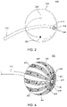
- FIG. 2 is an example balloon configuration with opposing transducers for the distal end of a catheter used in connection with the example medical system of FIG. 1 .
- FIGS. 3A-C is a series of diagrams illustrating a method of utilizing the example balloon configuration of FIG. 2 .
- FIG. 4 is an alternative example balloon configuration for the distal end of a catheter used in connection with the example medical system of FIG. 1 .
- FIGS. 5A and 5B are illustrations of an example probe tool configuration for the distal end of a catheter used in connection with the example medical system of FIG. 1 .
- FIG. 1 is an illustration of an example medical system 20 that is used to generate and display information 52 during a mapping, diagnostic or other medical procedure and to control the deployment of various probes within a subject.
- the example system includes a probe 22 , such as an intracardiac catheter, a console 24 and an associated probe control unit 25 .
- the probe 22 is used for diagnostic or therapeutic treatment, such as for example, mapping electrical potentials in a heart 26 of a patient 28 or performing an ablation procedure.
- the probe 22 can be used, mutatis mutandis, for other therapeutic and/or diagnostic purposes in the heart, lungs, or in other body organs and ear, nose, and throat (ENT) procedures.
- An operator 30 can, for example, insert the probe 22 into the vascular system of the patient 28 using the probe control unit so that a distal end 32 of the probe 22 enters a chamber of the patient's heart 26 .
- the console 24 can use magnetic position sensing to determine position coordinates of the distal end 32 inside the heart 26 .
- a driver circuit 34 in the console 24 may drive field generators 36 to generate magnetic fields within the body of the patient 28 .
- the field generators 36 can include coils that may be placed below the torso of the patient 28 at known positions external to the patient 28 . These coils may generate magnetic fields in a predefined working volume that contains the heart 26 .
- a position sensor 38 within the distal end 32 of the probe 22 can generate electrical signals in response to these magnetic fields.
- a signal processor 40 can process these signals in order to determine the position coordinates of the distal end 32 , including both location and orientation coordinates.
- Known methods of position sensing described hereinabove are implemented in the CARTOTM mapping system produced by Biosense Webster Inc., of Diamond Bar, Calif., and is described in detail in the patents and the patent applications cited herein.
- the position sensor 38 is configured to transmit a signal to the console 24 that is indicative of the location coordinates of the distal end 32 .
- the position sensor 38 can include one or more miniature coils, and typically can include multiple coils oriented along different axes.
- the position sensor 38 can comprise either another type of magnetic sensor, or position transducers of other types, such as impedance-based or ultrasonic position sensors.
- the position sensor 38 can include one or more sets of opposing transducers.
- the probe 22 can also include a force sensor 54 contained within the distal end 32 .
- the force sensor 54 can measure a force applied by the distal end 32 to the endocardial tissue of the heart 26 and generating a signal that is sent to the console 24 .
- the force sensor 54 can include a magnetic field transmitter and a receiver connected by a spring in the distal end 32 , and can generate an indication of the force based on measuring a deflection of the spring. Further details of this type of probe and force sensor are described in U.S. Patent Application Publications 2009/0093806 and 2009/0138007, and are incorporated herein by reference as if fully set forth.
- the distal end 32 can include another type of force sensor that can use, for example, fiber optics or impedance measurements.
- the probe 22 can include an electrode 48 coupled to the distal end 32 and configured to function as an impedance-based position transducer. Additionally or alternatively, the electrode 48 can be configured to measure a certain physiological property, for example the local surface electrical potential of the cardiac tissue at one or more of the multiple locations. The electrode 48 can be configured to apply radio frequency (RF) energy to ablate endocardial tissue in the heart 26 .
- RF radio frequency
- example medical system 20 can be configured to measure the position of the distal end 32 using magnetic-based sensors
- other position tracking techniques can be used (e.g., impedance-based sensors).
- Magnetic position tracking techniques are described, for example, in U.S. Pat. Nos. 5,391,199, 5,443,489, 6,788,967, 6,690,963, 5,558,091, 6,172,499, and 6,177,792, and are incorporated herein by reference as if fully set forth.
- Impedance-based position tracking techniques are described, for example, in U.S. Pat. Nos. 5,983,126 and 5,944,022, and are incorporated herein by reference as if fully set forth.
- the signal processor 40 can be included in a general-purpose computer with a suitable front end and interface circuits for receiving signals from the probe 22 and controlling the other components of the console 24 .
- the signal processor 40 can be programmed, using software, to carry out the functions that are described herein.
- the software can be downloaded to the console 24 in electronic form, over a network, for example, or it can be provided on non-transitory tangible media, such as optical, magnetic or electronic memory media.
- some or all of the functions of the signal processor 40 can be performed by dedicated or programmable digital hardware components.
- the console 24 can also be connected by a cable 44 to external sensors 46 .
- the external sensors 46 can include body surface electrodes and/or position sensors that can be attached to the patient's skin using, for example, adhesive patches.
- the body surface electrodes can detect electrical impulses generated by the polarization and depolarization of cardiac tissue.
- the position sensors can use advanced catheter location and/or magnetic position sensors to locate the probe 22 during use.
- the external sensors 46 can be embedded in a vest that is configured to be worn by the patient 28 .
- the external sensors 46 can aid in identifying and tracking the respiration cycle of the patient 28 .
- the external sensors 46 can transmit information to the console 24 via the cable 44 .
- the probe 22 , and the external sensors 46 can communicate with the console 24 and one another via a wireless interface.
- a wireless catheter which is not physically connected to signal processing and/or computing apparatus. Rather, a transmitter/receiver is attached to the proximal end of the catheter. The transmitter/receiver communicates with a signal processing and/or computer apparatus using wireless communication methods, such as infrared (IR), radio frequency (RF), wireless, Bluetooth®, acoustic or other transmissions.
- IR infrared
- RF radio frequency
- Bluetooth® acoustic or other transmissions.
- the probe 22 can be equipped with a wireless digital interface that can communicate with a corresponding input/output (I/O) interface 42 in the console 24 .
- the wireless digital interface and the I/O interface 42 can operate in accordance with any suitable wireless communication standard that is known in the art, such as IR, RF, Bluetooth, one of the IEEE 802.11 families of standards, or the HiperLAN standard.
- the external sensors 46 can include one or more wireless sensor nodes integrated on a flexible substrate.
- the one or more wireless sensor nodes can include a wireless transmit/receive unit (WTRU) enabling local digital signal processing, a radio link, and a power supply such as miniaturized rechargeable battery.
- WTRU wireless transmit/receive unit
- the I/O interface 42 can enable the console 24 to interact with the probe 22 and the external sensors 46 . Based on the electrical impulses received from the external sensors 46 and signals received from the probe 22 via the I/O interface 42 and other components of the medical system 20 , the signal processor 40 can generate the information 52 , which can be shown on a display 50 .
- the information 52 can be represented in the form of data or graphic interpretation such as, for example, a chart, a photograph, video or other type of graphic display.
- the signal processor 40 can present the information 52 and/or can store data representing the information 52 in a memory 58 .
- the memory 58 can include any suitable volatile and/or non-volatile memory, such as random access memory or a hard disk drive.
- the probe control unit 25 can be configured to be operated by an operator 30 to manipulate the probe based on the information 52 which is selectable using one or more input devices 59 .
- the medical system 20 can include a second operator that manipulates the console 24 while the operator 30 operates the probe control unit 25 to manipulate the probe 22 based on the displayed information 52 .
- An interventional catheter based procedure can involve a technique referred to as cardiac ablation.
- a catheter is usually advanced from the groin area of a patient into the heart. Once in place, radio frequency (RF) energy can be delivered through the catheter to a specific location within a chamber of the subject's heart with the goal of re-establishing proper heart conduction.
- RF radio frequency
- the mechanics of the construction and use of the probe control device 25 to move and position the distal end of a probe is within the state of the art such as employed in the CARTOTM mapping system referenced above.
- the operation of the probe control device 25 to control the movement of the distal end of the probe is dependent on obtaining accurate and precise data of its movement and position.
- On-probe sensors such as ultra sound transducers are capable of very precise sensing of the relative location of the walls of organs, vessels and other tissues to provide very precise positioning data of a probe.
- ultrasound transducers for determining the position data, a small “dead zone” is typically produced just in front of the transducer within which the sensor cannot properly operate.
- an ultrasound transducer can transmit a pulse of sound and then listen for a returning sound, i.e. echo.
- the sensor detects the echo and associates the echo with the surface of the target.
- the amount of time between the initial pulse and the returning echo is used to calculate the distance between the transducer and the target surface.
- tracking data can be generated with respect to the transducer and an object in front of it, such as the wall of an organ or vessel, using the determined distances calculated from the returning echoes.
- speed is also readily calculated from returning echoes when transmitting pulses at regular time intervals of a known frequency. Calculations derived from speed and distance data are then used to track relative movement of the transducer and, accordingly, the distal probe end, to which it is attached.
- a transducer Since a transducer both transmits and receives pulses, when a reflective object is too close to the transducer, it sometimes can mistake its own pulse (i.e., the vibration from its own pulse) for a returning signal.
- the sensor on the transducer can be configured to ignore the vibration from all pulses as long as necessary for the vibration to stop so that is does not sense its transmitted pulse directly.
- the transducer also ignores the echo signal from a close object. For example, a catheter's transducer may be moved too close to the wall of a heart chamber for the transducer to properly sense it since the transducer begins to ignore signals bouncing off that wall.
- the distance a pulse travels during the time the transducer transmits a pulse and can reliably sense an echo thereof can be referred to as a blanking distance or a dead zone.
- the blanking distance becomes an issue when a transducer is used to measure objects within a very close distance, for example, less than a half millimeter, in the context of transducers of the type used with a medical probe.
- FIG. 2 provides an example of use of a set of opposing transducers that are able to compensate for the blanking region of either.
- FIG. 2 illustrates an example configuration of a distal end portion 200 for the probe 22 of FIG. 1 .
- a balloon 220 is attached at a predetermined location to a probe sheath 210 .
- the sheath 210 traverses through the balloon 220 from an opening on a proximal end and, in this example, exits the balloon 220 from an opening 218 on a distal end.
- the sheath 210 terminates in an end 230 from which a tool 240 or other device can extend.
- the balloon 220 includes a first transducer 250 mounted on one side of the balloon 220 and a second transducer 260 mounted on an opposing side.
- the first transducer 250 can transmit a signal at a first frequency
- the second transducer 260 can transmit a signal at a second, different frequency.
- Other differentiation techniques known in the art can be employed alone or in combination with frequency differentiation.
- the example probe end portion 200 is shown positioned in a walled area 300 of a subject having a first wall 310 and an opposing wall 320 .
- the balloon 220 is positioned at a position far enough away from both the walls 310 , 320 such that the first transducer can sense the first wall 310 and the opposing transducer 260 can sense the opposing wall 320 .
- Signals from both transducers are used for providing the information to the signal processor 40 ( FIG. 1 ) which in turn provides the probe operator 30 position data 52 on the display 50 in a desired format, which may include a split screen of graphics and distance/tracking data generated from the transducer signals.
- the processor can use additional signals from both transducers 250 , 260 to change the probe position displayed on the display 50 to reflect the changed probe position, as well as tracking data that can include speed and a motion vector.
- the changes in position display and tracking data can be generated using both transducers to provide very precise information regarding the movement of the balloon 220 and accordingly, the distal end of the probe 22 , until the balloon enters a blanking region 330 relative to the first transducer 250 .
- the blanking region is defined by a distance in front of the first transducer 250 within which the first transducer in unable to properly operate to sense the distance of the wall 310 directly in front of it.
- the opposing transducer is still able to provide position and tracking data with respect to the opposing wall 320 and that information can be used to continue an accurate display of the movement of the balloon as it travels the short distance through the blanking area to enable the operator to control the balloon to a precise position in contact with the wall 310 illustrated in FIG. 3C .
- the probe When using a balloon, such as balloon 220 , typically the probe is initially inserted into a subject in a deflated orientation. When the distal end of the probe is positioned within a desired walled cavity, the balloon is then expanded. If the balloon is not expanded to a precise degree, there may be deviation in the expected distance between the first and second transducers 250 and 260 . Such distance is an additional factor that can be used in generating precise position and movement tracking information regarding the movement of the balloon.
- the first transducer 250 can receive a signal from the second transducer 260 and/or an echo signal reflected from a target surface but originating as a pulse from the second transducer 260 .
- the second transducer 260 can receive a signal from the first transducer 250 and/or a signal reflected from a target surface but originating as a pulse from the first transducer 250 .
- the system can use the received signals and/or echoes to correlate the precise distance between the first transducer 250 and the second transducer 260 .
- FIG. 4 is an illustration of a further example of a distal end portion 400 of the probe 22 employing opposing transducers.
- a balloon 420 is attached at a predetermined location to a probe sheath 410 .
- the sheath 410 traverses through the balloon 420 from an opening on a proximal end of the balloon 420 and terminates at the opposite side of the balloon 420 at an opening 418 on a distal end.
- the sheath 410 includes an opening 430 from which a tool or other device, not shown, can extend.
- the balloon 420 includes an array of transducer supporting members 450 , each including a plurality of transducer elements 460 .
- Each supporting member 450 is associated with a second supporting member to define a complementary pair 470 of supporting members 450 that are preferably, though not exclusively, 180 degrees opposite from one another.
- the transducers 460 are configured to sense different portions of walls of a walled cavity into which the distal end of the probe is located.
- Each transducer element 460 on each supporting member 450 can be paired with a transducer on the complementary supporting member 450 of a supporting member pair 470 to define sets of transducer elements 460 opposite each other on the surface of the balloon 420 .
- the sets of transducer elements can each consist of two elements 460 at an angle of 180 degrees with respect to an axis of the balloon so that they are spaced apart by a distance equal to the diameter of the balloon when the balloon is inflated to a spherical configuration.
- Other transducer sets may be defined such as sets of three transducers defining the vertices of equilateral triangles or sets of four transducers defining the vertices of regular tetrahedrons.
- all of the transducers 460 may define a single set.
- Sets of two transducer elements 460 can be operated to sense opposing walls of a walled area as explained above with respect to the transducers 250 and 260 in FIGS. 2 and 3A -C.
- Sets of three or more transducers may be defined so that when one transducer of such a set enters a blanking region close to a wall portion that it senses, tracking data from the other transducers in the set is used to control navigation of the probe toward that wall.
- data from multiple sets of transducer elements can be used by the processor 40 ( FIG. 1 ) to generate precise position and tracking information 52 that is displayed to the operator 60 .
- opposite is not intended to be limited to 180 degrees opposite.
- the “opposing” transducers need only be arranged such that when one transducer of a set enters a blanking region close to a wall portion sensed by that transducer, tracking data from the other transducer(s) in the set is sufficient to control navigation of the probe toward that wall portion. It will be appreciated that it is possible for two transducers of a set to both be sensing a different portion of the same wall. Accordingly, as used herein, the term “opposing wall” includes a different portion of the same wall.
- FIGS. 5A and 5B illustrate a further example of use of a set of opposing transducers that can compensate for the blanking region of either transducer.
- a further example configuration of a distal end portion 500 is provided for probe 22 .
- a tool 520 is extendable from the distal end of a probe sheath 510 .
- the tool 520 itself includes a first transducer 530 mounted on one side and a second transducer 540 mounted on an opposing side.
- the opposing transducer elements 530 , 540 can be operated to sense opposing walls of a walled area as explained above with respect to the transducers 250 and 260 in FIGS. 2 and 3A -C.
- the sets of transducers can comprise transducers at different known angular orientations to one another, as well as transducer sets including more than two transducers, such as referenced above with respect to FIG. 4 .
- the relative angular orientation of each transducer may be taken into account in the calculation of positioning and tracking data that can be used to compensate for any one of the transducers of the set that enters a blanking region where it cannot properly operate.
Landscapes
- Health & Medical Sciences (AREA)
- Life Sciences & Earth Sciences (AREA)
- Engineering & Computer Science (AREA)
- Heart & Thoracic Surgery (AREA)
- Veterinary Medicine (AREA)
- Public Health (AREA)
- General Health & Medical Sciences (AREA)
- Animal Behavior & Ethology (AREA)
- Biomedical Technology (AREA)
- Surgery (AREA)
- Molecular Biology (AREA)
- Medical Informatics (AREA)
- Nuclear Medicine, Radiotherapy & Molecular Imaging (AREA)
- Biophysics (AREA)
- Physics & Mathematics (AREA)
- Cardiology (AREA)
- Pathology (AREA)
- Robotics (AREA)
- Pulmonology (AREA)
- Anesthesiology (AREA)
- Hematology (AREA)
- Radiology & Medical Imaging (AREA)
- Otolaryngology (AREA)
- Plasma & Fusion (AREA)
- Human Computer Interaction (AREA)
- Ultra Sonic Daignosis Equipment (AREA)
Abstract
Description
Claims (20)
Priority Applications (6)
| Application Number | Priority Date | Filing Date | Title |
|---|---|---|---|
| US15/680,292 US11471219B2 (en) | 2017-08-18 | 2017-08-18 | Catheter probe navigation method and device employing opposing transducers |
| CN201880053656.6A CN110996778B (en) | 2017-08-18 | 2018-08-15 | Catheter probe navigation method and apparatus employing opposing transducers |
| PCT/IB2018/056118 WO2019035000A1 (en) | 2017-08-18 | 2018-08-15 | Catheter probe navigation method and device employing opposing transducers |
| EP18779752.7A EP3668378B1 (en) | 2017-08-18 | 2018-08-15 | Catheter probe navigation device employing opposing transducers |
| JP2020509011A JP7230003B2 (en) | 2017-08-18 | 2018-08-15 | Catheter probe navigation method and apparatus using opposed transducers |
| IL272260A IL272260B2 (en) | 2017-08-18 | 2020-01-26 | Catheter probe navigation method and device employing opposing transducers |
Applications Claiming Priority (1)
| Application Number | Priority Date | Filing Date | Title |
|---|---|---|---|
| US15/680,292 US11471219B2 (en) | 2017-08-18 | 2017-08-18 | Catheter probe navigation method and device employing opposing transducers |
Publications (2)
| Publication Number | Publication Date |
|---|---|
| US20190053854A1 US20190053854A1 (en) | 2019-02-21 |
| US11471219B2 true US11471219B2 (en) | 2022-10-18 |
Family
ID=63713917
Family Applications (1)
| Application Number | Title | Priority Date | Filing Date |
|---|---|---|---|
| US15/680,292 Active 2039-02-10 US11471219B2 (en) | 2017-08-18 | 2017-08-18 | Catheter probe navigation method and device employing opposing transducers |
Country Status (6)
| Country | Link |
|---|---|
| US (1) | US11471219B2 (en) |
| EP (1) | EP3668378B1 (en) |
| JP (1) | JP7230003B2 (en) |
| CN (1) | CN110996778B (en) |
| IL (1) | IL272260B2 (en) |
| WO (1) | WO2019035000A1 (en) |
Citations (23)
| Publication number | Priority date | Publication date | Assignee | Title |
|---|---|---|---|---|
| US5391199A (en) | 1993-07-20 | 1995-02-21 | Biosense, Inc. | Apparatus and method for treating cardiac arrhythmias |
| US5558091A (en) | 1993-10-06 | 1996-09-24 | Biosense, Inc. | Magnetic determination of position and orientation |
| US5590659A (en) | 1994-09-15 | 1997-01-07 | Intravascular Research Limited | Ultrasonic visualization method and apparatus |
| US5865801A (en) * | 1995-07-18 | 1999-02-02 | Houser; Russell A. | Multiple compartmented balloon catheter with external pressure sensing |
| US5944022A (en) | 1997-04-28 | 1999-08-31 | American Cardiac Ablation Co. Inc. | Catheter positioning system |
| US5983126A (en) | 1995-11-22 | 1999-11-09 | Medtronic, Inc. | Catheter location system and method |
| US6172499B1 (en) | 1999-10-29 | 2001-01-09 | Ascension Technology Corporation | Eddy current error-reduced AC magnetic position measurement system |
| US6177792B1 (en) | 1996-03-26 | 2001-01-23 | Bisense, Inc. | Mutual induction correction for radiator coils of an objects tracking system |
| US6266551B1 (en) | 1996-02-15 | 2001-07-24 | Biosense, Inc. | Catheter calibration and usage monitoring system |
| US6445944B1 (en) | 1999-02-01 | 2002-09-03 | Scimed Life Systems | Medical scanning system and related method of scanning |
| US6547788B1 (en) * | 1997-07-08 | 2003-04-15 | Atrionx, Inc. | Medical device with sensor cooperating with expandable member |
| US6690963B2 (en) | 1995-01-24 | 2004-02-10 | Biosense, Inc. | System for determining the location and orientation of an invasive medical instrument |
| US20060253028A1 (en) * | 2005-04-20 | 2006-11-09 | Scimed Life Systems, Inc. | Multiple transducer configurations for medical ultrasound imaging |
| US7291110B2 (en) * | 2001-10-12 | 2007-11-06 | Boston Scientific Corporation | Catheter lesion diagnostics |
| US20090093806A1 (en) | 2007-10-08 | 2009-04-09 | Assaf Govari | Catheter with pressure sensing |
| US20090138007A1 (en) | 2007-10-08 | 2009-05-28 | Assaf Govari | High-sensitivity pressure-sensing probe |
| US20100076299A1 (en) * | 2008-09-22 | 2010-03-25 | Minnow Medical, Inc. | Inducing Desirable Temperature Effects On Body Tissue Using Alternate Energy Sources |
| WO2012122517A2 (en) | 2011-03-10 | 2012-09-13 | Acutus Medical, Inc. | Device and method for the geometric determination of electrical dipole densities on the cardiac wall |
| WO2014124231A1 (en) | 2013-02-08 | 2014-08-14 | Acutus Medical, Inc. | Expandable catheter assembly with flexible printed circuit board |
| WO2014188430A2 (en) | 2013-05-23 | 2014-11-27 | CardioSonic Ltd. | Devices and methods for renal denervation and assessment thereof |
| WO2015148470A1 (en) | 2014-03-25 | 2015-10-01 | Acutus Medical, Inc. | Cardiac analysis user interface system and method |
| US20160051321A1 (en) * | 2013-04-08 | 2016-02-25 | Amr Salahieh | Tissue ablation and monitoring |
| WO2016183285A1 (en) | 2015-05-12 | 2016-11-17 | Acutus Medical, Inc. | Ultrasound sequencing system and method |
Family Cites Families (4)
| Publication number | Priority date | Publication date | Assignee | Title |
|---|---|---|---|---|
| JP4565594B2 (en) * | 1999-03-02 | 2010-10-20 | アトリオニクス・インコーポレーテツド | Pulmonary resection device positioning system |
| JP2006517117A (en) * | 2003-01-16 | 2006-07-20 | ガリル メディカル リミテッド | Apparatus, system, and method for detecting, locating, and identifying plaque-induced stenosis of blood vessels |
| EP2398548B1 (en) * | 2009-02-17 | 2017-04-19 | The Board Of Trustees Of The Leland | Closure device |
| JP6366591B2 (en) * | 2012-10-23 | 2018-08-01 | コーニンクレッカ フィリップス エヌ ヴェKoninklijke Philips N.V. | Space shape determination instrument |
-
2017
- 2017-08-18 US US15/680,292 patent/US11471219B2/en active Active
-
2018
- 2018-08-15 WO PCT/IB2018/056118 patent/WO2019035000A1/en unknown
- 2018-08-15 CN CN201880053656.6A patent/CN110996778B/en active Active
- 2018-08-15 JP JP2020509011A patent/JP7230003B2/en active Active
- 2018-08-15 EP EP18779752.7A patent/EP3668378B1/en active Active
-
2020
- 2020-01-26 IL IL272260A patent/IL272260B2/en unknown
Patent Citations (25)
| Publication number | Priority date | Publication date | Assignee | Title |
|---|---|---|---|---|
| US5391199A (en) | 1993-07-20 | 1995-02-21 | Biosense, Inc. | Apparatus and method for treating cardiac arrhythmias |
| US5443489A (en) | 1993-07-20 | 1995-08-22 | Biosense, Inc. | Apparatus and method for ablation |
| US5558091A (en) | 1993-10-06 | 1996-09-24 | Biosense, Inc. | Magnetic determination of position and orientation |
| US5590659A (en) | 1994-09-15 | 1997-01-07 | Intravascular Research Limited | Ultrasonic visualization method and apparatus |
| US6690963B2 (en) | 1995-01-24 | 2004-02-10 | Biosense, Inc. | System for determining the location and orientation of an invasive medical instrument |
| US5865801A (en) * | 1995-07-18 | 1999-02-02 | Houser; Russell A. | Multiple compartmented balloon catheter with external pressure sensing |
| US5983126A (en) | 1995-11-22 | 1999-11-09 | Medtronic, Inc. | Catheter location system and method |
| US6266551B1 (en) | 1996-02-15 | 2001-07-24 | Biosense, Inc. | Catheter calibration and usage monitoring system |
| US6177792B1 (en) | 1996-03-26 | 2001-01-23 | Bisense, Inc. | Mutual induction correction for radiator coils of an objects tracking system |
| US5944022A (en) | 1997-04-28 | 1999-08-31 | American Cardiac Ablation Co. Inc. | Catheter positioning system |
| US6788967B2 (en) | 1997-05-14 | 2004-09-07 | Biosense, Inc. | Medical diagnosis, treatment and imaging systems |
| US6547788B1 (en) * | 1997-07-08 | 2003-04-15 | Atrionx, Inc. | Medical device with sensor cooperating with expandable member |
| US6445944B1 (en) | 1999-02-01 | 2002-09-03 | Scimed Life Systems | Medical scanning system and related method of scanning |
| US6172499B1 (en) | 1999-10-29 | 2001-01-09 | Ascension Technology Corporation | Eddy current error-reduced AC magnetic position measurement system |
| US7291110B2 (en) * | 2001-10-12 | 2007-11-06 | Boston Scientific Corporation | Catheter lesion diagnostics |
| US20060253028A1 (en) * | 2005-04-20 | 2006-11-09 | Scimed Life Systems, Inc. | Multiple transducer configurations for medical ultrasound imaging |
| US20090093806A1 (en) | 2007-10-08 | 2009-04-09 | Assaf Govari | Catheter with pressure sensing |
| US20090138007A1 (en) | 2007-10-08 | 2009-05-28 | Assaf Govari | High-sensitivity pressure-sensing probe |
| US20100076299A1 (en) * | 2008-09-22 | 2010-03-25 | Minnow Medical, Inc. | Inducing Desirable Temperature Effects On Body Tissue Using Alternate Energy Sources |
| WO2012122517A2 (en) | 2011-03-10 | 2012-09-13 | Acutus Medical, Inc. | Device and method for the geometric determination of electrical dipole densities on the cardiac wall |
| WO2014124231A1 (en) | 2013-02-08 | 2014-08-14 | Acutus Medical, Inc. | Expandable catheter assembly with flexible printed circuit board |
| US20160051321A1 (en) * | 2013-04-08 | 2016-02-25 | Amr Salahieh | Tissue ablation and monitoring |
| WO2014188430A2 (en) | 2013-05-23 | 2014-11-27 | CardioSonic Ltd. | Devices and methods for renal denervation and assessment thereof |
| WO2015148470A1 (en) | 2014-03-25 | 2015-10-01 | Acutus Medical, Inc. | Cardiac analysis user interface system and method |
| WO2016183285A1 (en) | 2015-05-12 | 2016-11-17 | Acutus Medical, Inc. | Ultrasound sequencing system and method |
Non-Patent Citations (2)
| Title |
|---|
| Goldberg, Richard L., Stephen W. Smith, and Lewis F. Brown. "In vivo imaging using a copolymer phased array." Ultrasonic imaging 14, No. 3 (1992): 234-248. * |
| International Search Report and Written Opinion of the International Searching Authority for PCT International Application No. PCT/IB2018/056118 dated Dec. 7, 2018. |
Also Published As
| Publication number | Publication date |
|---|---|
| CN110996778A (en) | 2020-04-10 |
| US20190053854A1 (en) | 2019-02-21 |
| WO2019035000A1 (en) | 2019-02-21 |
| EP3668378B1 (en) | 2022-07-06 |
| JP2020531108A (en) | 2020-11-05 |
| IL272260B2 (en) | 2023-07-01 |
| EP3668378A1 (en) | 2020-06-24 |
| JP7230003B2 (en) | 2023-02-28 |
| IL272260A (en) | 2020-03-31 |
| CN110996778B (en) | 2023-07-04 |
| IL272260B1 (en) | 2023-03-01 |
Similar Documents
| Publication | Publication Date | Title |
|---|---|---|
| US11678863B2 (en) | System and method for providing auditory guidance in medical systems | |
| US20030093067A1 (en) | Systems and methods for guiding catheters using registered images | |
| JPH11332851A (en) | Device and method for positioning active region | |
| CN109589091B (en) | Interactive display for selected ECG channels | |
| JP2014104363A (en) | Location sensing using local coordinate system | |
| US20220054803A1 (en) | Adjustable balloon fixation for a sheath | |
| KR102291452B1 (en) | Surgical assistance device, control method therefor, and surgical assistance system | |
| EP3320944A1 (en) | Multi-electrode catheter for preventing physiological fluid flow restriction | |
| US11471219B2 (en) | Catheter probe navigation method and device employing opposing transducers | |
| EP3476347B1 (en) | System for gap detection in ablation lines | |
| CN111093510B (en) | Methods and apparatus for performing non-fluoroscopic transseptal procedures |
Legal Events
| Date | Code | Title | Description |
|---|---|---|---|
| AS | Assignment |
Owner name: BIOSENSE WEBSTER (ISRAEL) LTD., ISRAEL Free format text: ASSIGNMENT OF ASSIGNORS INTEREST;ASSIGNOR:ALTMANN, ANDRES CLAUDIO;REEL/FRAME:043639/0038 Effective date: 20170905 |
|
| STPP | Information on status: patent application and granting procedure in general |
Free format text: DOCKETED NEW CASE - READY FOR EXAMINATION |
|
| STPP | Information on status: patent application and granting procedure in general |
Free format text: NON FINAL ACTION MAILED |
|
| STPP | Information on status: patent application and granting procedure in general |
Free format text: RESPONSE TO NON-FINAL OFFICE ACTION ENTERED AND FORWARDED TO EXAMINER |
|
| STPP | Information on status: patent application and granting procedure in general |
Free format text: FINAL REJECTION MAILED |
|
| STPP | Information on status: patent application and granting procedure in general |
Free format text: ADVISORY ACTION MAILED |
|
| STPP | Information on status: patent application and granting procedure in general |
Free format text: NON FINAL ACTION MAILED |
|
| STPP | Information on status: patent application and granting procedure in general |
Free format text: NON FINAL ACTION MAILED |
|
| STPP | Information on status: patent application and granting procedure in general |
Free format text: RESPONSE TO NON-FINAL OFFICE ACTION ENTERED AND FORWARDED TO EXAMINER |
|
| STCV | Information on status: appeal procedure |
Free format text: NOTICE OF APPEAL FILED |
|
| STCV | Information on status: appeal procedure |
Free format text: APPEAL BRIEF (OR SUPPLEMENTAL BRIEF) ENTERED AND FORWARDED TO EXAMINER |
|
| STCV | Information on status: appeal procedure |
Free format text: EXAMINER'S ANSWER TO APPEAL BRIEF MAILED |
|
| STCV | Information on status: appeal procedure |
Free format text: REPLY BRIEF FILED AND FORWARDED TO BPAI |
|
| STCV | Information on status: appeal procedure |
Free format text: APPEAL READY FOR REVIEW |
|
| STCV | Information on status: appeal procedure |
Free format text: ON APPEAL -- AWAITING DECISION BY THE BOARD OF APPEALS |
|
| STCV | Information on status: appeal procedure |
Free format text: BOARD OF APPEALS DECISION RENDERED |
|
| STPP | Information on status: patent application and granting procedure in general |
Free format text: NOTICE OF ALLOWANCE MAILED -- APPLICATION RECEIVED IN OFFICE OF PUBLICATIONS |
|
| STPP | Information on status: patent application and granting procedure in general |
Free format text: PUBLICATIONS -- ISSUE FEE PAYMENT VERIFIED |
|
| STCF | Information on status: patent grant |
Free format text: PATENTED CASE |
|
| CC | Certificate of correction |