US11426231B2 - Arthroscopic devices and methods - Google Patents
Arthroscopic devices and methods Download PDFInfo
- Publication number
- US11426231B2 US11426231B2 US15/855,684 US201715855684A US11426231B2 US 11426231 B2 US11426231 B2 US 11426231B2 US 201715855684 A US201715855684 A US 201715855684A US 11426231 B2 US11426231 B2 US 11426231B2
- Authority
- US
- United States
- Prior art keywords
- handpiece
- sleeve
- thin
- medical device
- ceramic
- Prior art date
- Legal status (The legal status is an assumption and is not a legal conclusion. Google has not performed a legal analysis and makes no representation as to the accuracy of the status listed.)
- Active, expires
Links
Images


Classifications
-
- A—HUMAN NECESSITIES
- A61—MEDICAL OR VETERINARY SCIENCE; HYGIENE
- A61B—DIAGNOSIS; SURGERY; IDENTIFICATION
- A61B18/00—Surgical instruments, devices or methods for transferring non-mechanical forms of energy to or from the body
- A61B18/04—Surgical instruments, devices or methods for transferring non-mechanical forms of energy to or from the body by heating
- A61B18/12—Surgical instruments, devices or methods for transferring non-mechanical forms of energy to or from the body by heating by passing a current through the tissue to be heated, e.g. high-frequency current
- A61B18/14—Probes or electrodes therefor
- A61B18/1482—Probes or electrodes therefor having a long rigid shaft for accessing the inner body transcutaneously in minimal invasive surgery, e.g. laparoscopy
-
- A—HUMAN NECESSITIES
- A61—MEDICAL OR VETERINARY SCIENCE; HYGIENE
- A61B—DIAGNOSIS; SURGERY; IDENTIFICATION
- A61B18/00—Surgical instruments, devices or methods for transferring non-mechanical forms of energy to or from the body
- A61B18/04—Surgical instruments, devices or methods for transferring non-mechanical forms of energy to or from the body by heating
- A61B18/12—Surgical instruments, devices or methods for transferring non-mechanical forms of energy to or from the body by heating by passing a current through the tissue to be heated, e.g. high-frequency current
- A61B18/1206—Generators therefor
-
- A—HUMAN NECESSITIES
- A61—MEDICAL OR VETERINARY SCIENCE; HYGIENE
- A61B—DIAGNOSIS; SURGERY; IDENTIFICATION
- A61B18/00—Surgical instruments, devices or methods for transferring non-mechanical forms of energy to or from the body
- A61B18/04—Surgical instruments, devices or methods for transferring non-mechanical forms of energy to or from the body by heating
- A61B18/042—Surgical instruments, devices or methods for transferring non-mechanical forms of energy to or from the body by heating using additional gas becoming plasma
-
- A—HUMAN NECESSITIES
- A61—MEDICAL OR VETERINARY SCIENCE; HYGIENE
- A61B—DIAGNOSIS; SURGERY; IDENTIFICATION
- A61B18/00—Surgical instruments, devices or methods for transferring non-mechanical forms of energy to or from the body
- A61B2018/00053—Mechanical features of the instrument of device
- A61B2018/00059—Material properties
- A61B2018/00089—Thermal conductivity
- A61B2018/00101—Thermal conductivity low, i.e. thermally insulating
-
- A—HUMAN NECESSITIES
- A61—MEDICAL OR VETERINARY SCIENCE; HYGIENE
- A61B—DIAGNOSIS; SURGERY; IDENTIFICATION
- A61B18/00—Surgical instruments, devices or methods for transferring non-mechanical forms of energy to or from the body
- A61B2018/00571—Surgical instruments, devices or methods for transferring non-mechanical forms of energy to or from the body for achieving a particular surgical effect
- A61B2018/00577—Ablation
-
- A—HUMAN NECESSITIES
- A61—MEDICAL OR VETERINARY SCIENCE; HYGIENE
- A61B—DIAGNOSIS; SURGERY; IDENTIFICATION
- A61B18/00—Surgical instruments, devices or methods for transferring non-mechanical forms of energy to or from the body
- A61B2018/00571—Surgical instruments, devices or methods for transferring non-mechanical forms of energy to or from the body for achieving a particular surgical effect
- A61B2018/00607—Coagulation and cutting with the same instrument
-
- A—HUMAN NECESSITIES
- A61—MEDICAL OR VETERINARY SCIENCE; HYGIENE
- A61B—DIAGNOSIS; SURGERY; IDENTIFICATION
- A61B18/00—Surgical instruments, devices or methods for transferring non-mechanical forms of energy to or from the body
- A61B2018/00571—Surgical instruments, devices or methods for transferring non-mechanical forms of energy to or from the body for achieving a particular surgical effect
- A61B2018/00619—Welding
-
- A—HUMAN NECESSITIES
- A61—MEDICAL OR VETERINARY SCIENCE; HYGIENE
- A61B—DIAGNOSIS; SURGERY; IDENTIFICATION
- A61B18/00—Surgical instruments, devices or methods for transferring non-mechanical forms of energy to or from the body
- A61B2018/00636—Sensing and controlling the application of energy
- A61B2018/00696—Controlled or regulated parameters
- A61B2018/00714—Temperature
-
- A—HUMAN NECESSITIES
- A61—MEDICAL OR VETERINARY SCIENCE; HYGIENE
- A61B—DIAGNOSIS; SURGERY; IDENTIFICATION
- A61B18/00—Surgical instruments, devices or methods for transferring non-mechanical forms of energy to or from the body
- A61B2018/00636—Sensing and controlling the application of energy
- A61B2018/00773—Sensed parameters
- A61B2018/00791—Temperature
-
- A—HUMAN NECESSITIES
- A61—MEDICAL OR VETERINARY SCIENCE; HYGIENE
- A61B—DIAGNOSIS; SURGERY; IDENTIFICATION
- A61B2218/00—Details of surgical instruments, devices or methods for transferring non-mechanical forms of energy to or from the body
- A61B2218/001—Details of surgical instruments, devices or methods for transferring non-mechanical forms of energy to or from the body having means for irrigation and/or aspiration of substances to and/or from the surgical site
- A61B2218/007—Aspiration
Definitions
- This invention relates to arthroscopic tissue cutting and removal devices by which anatomical tissues may be cut and removed from a joint or other site. More specifically, this invention relates to instruments configured for cutting and removing soft tissue with an electrosurgical device.
- the present invention provides an arthroscopic or other medical device comprising an elongate shaft having a proximal end and a working end. At least one electrode for treating tissue is located at the working end of the shaft, and a fluid outflow path extends proximally from the working end through a first channel portion in the shaft.
- a handpiece coupled to the proximal end of the shaft comprises a body with a second channel portion formed along an axis therein. The second channel is configured to receive a heated or other outflow from a proximal end of the first channel in the shaft, and the second channel runs along an axis of the handpiece.
- a thin wall sleeve is located in the handpiece so that it surrounds at least a portion of the second channel. The thin wall sleeve is surrounded by an air gap between an exterior surface of the thin wall sleeve and an inner surface of the body in order to limit heat transfer from the heated or other fluid outflow through the second channel.
- the thin wall sleeve may comprise a material having a thermal conductivity of less than 50 W/m ⁇ K., often having a thermal conductivity of less than 25 W/m ⁇ K.
- a fluid-tight chamber may be disposed in the handpiece to provide or define the air gap.
- the air gap may have a width transverse to the axis of at least 0.005′′ and the thin wall sleeve may extend over at least 60% of a length of the second channel portion in the handpiece, frequently extending over at least 80% of a length of the second channel portion in the handpiece, and often extending over substantially the entire length of the second channel portion in the handpiece.
- the shaft includes a proximal hub and so that it is detachable from the handpiece, allowing the handpiece to be cleaned and re-used while the shaft component is disposable.
- the handpiece may carry a motor and other system drive and control components for moving a component of the working end.
- the present invention provides an arthroscopic or other medical device comprising a handpiece having a body.
- a shaft having a proximal end attachable to a distal end of the handpiece extends distally from to a working end, and at least one electrode for treating tissue is located at the working end of the shaft.
- a fluid flow path extends from the working end proximally through a lumen in the shaft and through a channel in the handpiece.
- a sleeve is disposed in the lumen in the handpiece, where the sleeve and a surrounding portion of the body have a combined thermal conductivity in a transverse direction of less than 50 W/m ⁇ K, often less than 25 W/m ⁇ K, for limiting heat transfer from a fluid flow through the channel to the handpiece.
- the sleeve may be formed at least partly of a material selected from a group consisting of metal, ceramic or glass, for example being formed at least partly of stainless steel, being formed at least partly of a metal with a ceramic surface layer, or being formed at least partly of a ceramic which comprises an exterior or interior surface of the sleeve.
- the sleeve may be substantially surrounded by an air gap disposed between an exterior surface of the sleeve and an interior surface of the handpiece body, where the air gap may be formed or defined by a fluid-tight chamber in the handpiece.
- the air gap may have a width transverse to the axis of at least 0.005′′ and the thin wall sleeve may extend over at least 60% of a length of the second channel portion in the handpiece, frequently extending over at least 80% of a length of the second channel portion in the handpiece, and often extending over substantially the entire length of the second channel portion in the handpiece.
- the present invention provides a method of treating a patient's tissue comprising providing a handpiece coupled to an elongate shaft having an electrosurgical working end.
- the electrosurgical working end is introduced into a fluid-immersed tissue treatment site in the patient's body, and the electrosurgical working end is energized or otherwise activated to treat tissue which typically causes fluid in the site to become heated.
- a negative pressure source coupled to the handpiece is activated to initiate an outflow of heated fluid through a flow path through the shaft and the handpiece. Heat transfer from the flow of heated fluid through the handpiece is limited to maintain the handpiece temperature at temperature suitable for gripping with a human hand.
- the limiting step may comprise surrounding the flow path through the handpiece in a sleeve with an air gap.
- the limiting step may comprise surrounding the flow path through the handpiece in a sleeve with a material having a thermal conductivity of less than 50 W/m ⁇ K, often being less than 25 W/m ⁇ K.
- the sleeve may be formed at least partly of a material selected from a group consisting of metal, ceramic or glass, for example being formed at least partly of stainless steel, being formed at least partly of a metal with a ceramic surface layer, being formed at least partly of a ceramic which comprises an exterior or interior surface of the sleeve or the ceramic may comprise a surface of the lumen of the sleeve.
- FIG. 1 is a perspective view of a disposable arthroscopic cutter or burr assembly with a ceramic cutting member carried at the distal end of a rotatable inner sleeve with a window in the cutting member proximal to the cutting edges of the burr.
- FIG. 2 is an enlarged perspective view of the ceramic cutting member of the arthroscopic cutter or burr assembly of FIG. 1 .
- FIG. 3 is a perspective view of a handle body with a motor drive unit to which the burr assembly of FIG. 1 can be coupled, with the handle body including an LCD screen for displaying operating parameters of device during use together with a joystick and mode control actuators on the handle.
- FIG. 4 is an enlarged perspective view of the ceramic cutting member showing a manner of coupling the cutter to a distal end of the inner sleeve of the burr assembly.
- FIG. 5A is a cross-sectional view of a cutting assembly similar to that of FIG. 2 taken along line 5 A- 5 A showing the close tolerance between sharp cutting edges of a window in a ceramic cutting member and sharp lateral edges of the outer sleeve which provides a scissor-like cutting effect in soft tissue.
- FIG. 5B is a cross-sectional view of the cutting assembly of FIG. 5A with the ceramic cutting member in a different rotational position than in FIG. 5A .
- FIG. 6 is a perspective view of another ceramic cutting member carried at the distal end of an inner sleeve with a somewhat rounded distal nose and deeper flutes than the cutting member of FIGS. 2 and 4 , and with aspiration openings or ports formed in the flutes.
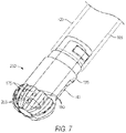
- FIG. 7 is a perspective view of another ceramic cutting member with cutting edges that extend around a distal nose of the cutter together with an aspiration window in the shaft portion and aspiration openings in the flutes.
- FIG. 8 is a perspective view of a ceramic housing carried at the distal end of the outer sleeve.
- FIG. 9 is a perspective of another variation of a ceramic member with cutting edges that includes an aspiration window and an electrode arrangement positioned distal to the window.
- FIG. 10 is an elevational view of a ceramic member and shaft of FIG. 9 showing the width and position of the electrode arrangement in relation to the window.
- FIG. 11 is an end view of a ceramic member of FIGS. 9-10 the outward periphery of the electrode arrangement in relation to the rotational periphery of the cutting edges of the ceramic member.
- FIG. 12A is a schematic view of the working end and ceramic cutting member of FIGS. 9-11 illustrating a step in a method of use.
- FIG. 12B is another view of the working end of FIG. 12A illustrating a subsequent step in a method of use to ablate a tissue surface.
- FIG. 12C is a view of the working end of FIG. 12A illustrating a method of tissue resection and aspiration of tissue chips to rapidly remove volumes of tissue.
- FIG. 13A is an elevational view of an alternative ceramic member and shaft similar to that of FIG. 9 illustrating an electrode variation.
- FIG. 13B is an elevational view of another ceramic member similar to that of FIG. 12A illustrating another electrode variation.
- FIG. 13C is an elevational view of another ceramic member similar to that of FIGS. 12A-12B illustrating another electrode variation.
- FIG. 14 is a perspective view of an alternative working end and ceramic cutting member with an electrode partly encircling a distal portion of an aspiration window.
- FIG. 15A is an elevational view of a working end variation with an electrode arrangement partly encircling a distal end of the aspiration window.
- FIG. 15B is an elevational view of another working end variation with an electrode positioned adjacent a distal end of the aspiration window.
- FIG. 16 is a perspective view of a variation of a working end and ceramic member with an electrode adjacent a distal end of an aspiration window having a sharp lateral edge for cutting tissue.
- FIG. 17 is a perspective view of a variation of a working end and ceramic member with four cutting edges and an electrode adjacent a distal end of an aspiration window.
- FIG. 18 is perspective view of an arthroscopic system including a control and power console, a footswitch and a re-usable motor carrying a motor drive unit.
- FIG. 19 is an enlarged sectional view of the distal end of the handle of FIG. 18 showing first and second electrical contacts therein for coupling RF energy to a disposable RF probe.
- FIG. 20 is a perspective view of a disposable RF probe of the type that couples to the re-useable handle of FIGS. 18-19 .
- FIG. 21 is a sectional perspective view of a proximal hub portion of the disposable RF probe of FIG. 20 .
- FIG. 22 is a sectional view of a variation of the hub of FIG. 21 which includes a fluid trap for collecting any conductive fluid migrating proximally in the hub.
- FIG. 23 is a sectional view of another variation of a handpiece that includes a fluid outflow channel with a surrounding air gap to prevent unwanted heating of the handpiece body.
- the present invention relates to bone cutting and removal devices and related methods of use.
- arthroscopic cutter or burr assembly for cutting or abrading bone that is disposable and is configured for detachable coupling to a non-disposable handle and motor drive component.
- This description of the general principles of this invention is not meant to limit the inventive concepts in the appended claims.
- the present invention provides a high-speed rotating ceramic cutter or burr that is configured for use in many arthroscopic surgical applications, including but not limited to treating bone in shoulders, knees, hips, wrists, ankles and the spine.
- the device includes a cutting member that is fabricated entirely of a ceramic material that is extremely hard and durable, as described in detail below.
- a motor drive is operatively coupled to the ceramic cutter to rotate the burr edges at speeds ranging from 3,000 rpm to 20,000 rpm.
- an arthroscopic cutter or burr assembly 100 is provided for cutting and removing hard tissue, which operates in a manner similar to commercially available metals shavers and burrs.
- FIG. 1 shows disposable burr assembly 100 that is adapted for detachable coupling to a handle 104 and motor drive unit 105 therein as shown in FIG. 3 .
- the cutter assembly 100 has a shaft 110 extending along longitudinal axis 115 that comprises an outer sleeve 120 and an inner sleeve 122 rotatably disposed therein with the inner sleeve 122 carrying a distal ceramic cutting member 125 .
- the shaft 110 extends from a proximal hub assembly 128 wherein the outer sleeve 120 is coupled in a fixed manner to an outer hub 140 A which can be an injection molded plastic, for example, with the outer sleeve 120 insert molded therein.
- the inner sleeve 122 is coupled to an inner hub 140 B (phantom view) that is configured for coupling to the motor drive unit 105 ( FIG. 3 ).
- the outer and inner sleeves 120 ands 122 typically can be a thin wall stainless steel tube, but other materials can be used such as ceramics, metals, plastics or combinations thereof.
- the outer sleeve 120 extends to distal sleeve region 142 that has an open end and cut-out 144 that is adapted to expose a window 145 in the ceramic cutting member 125 during a portion of the inner sleeve's rotation.
- the proximal hub 128 of the burr assembly 100 is configured with a J-lock, snap-fit feature, screw thread or other suitable feature for detachably locking the hub assembly 128 into the handle 104 .
- the outer hub 140 A includes a projecting key 146 that is adapted to mate with a receiving J-lock slot 148 in the handle 104 (see FIG. 3 ).
- the handle 104 is operatively coupled by electrical cable 152 to a controller 155 which controls the motor drive unit 105 .
- Actuator buttons 156 a , 156 b or 156 c on the handle 104 can be used to select operating modes, such as various rotational modes for the ceramic cutting member.
- a joystick 158 be moved forward and backward to adjust the rotational speed of the ceramic cutting member 125 .
- the rotational speed of the cutter can continuously adjustable, or can be adjusted in increments up to 20,000 rpm.
- negative pressure source 160 is coupled to aspiration tubing 162 which communicates with a flow channel in the handle 104 and lumen 165 in inner sleeve 122 which extends to window 145 in the ceramic cutting member 125 ( FIG. 2 ).
- the cutting member 125 comprises a ceramic body or monolith that is fabricated entirely of a technical ceramic material that has a very high hardness rating and a high fracture toughness rating, where “hardness” is measured on a Vickers scale and “fracture toughness” is measured in MPam 1/2 .
- Fracture toughness refers to a property which describes the ability of a material containing a flaw or crack to resist further fracture and expresses a material's resistance to brittle fracture. The occurrence of flaws is not completely avoidable in the fabrication and processing of any components.
- Types 304 and 316 stainless steel have hardness ratings of 1.7 and 2.1, respectively, which is low and a fracture toughness ratings of 228 and 278, respectively, which is very high.
- Human bone has a hardness rating of 0.8, so a stainless steel cutter is only about 2.5 times harder than bone.
- the high fracture toughness of stainless steel provides ductile behavior which results in rapid cleaving and wear on sharp edges of a stainless steel cutting member.
- hardness-toughness ratio is a useful term for characterizing ceramic materials that are suitable for the invention as can be understood form the Chart A below, which lists hardness and fracture toughness of cortical bone, a 304 stainless steel, and several technical ceramic materials.
- the hardness-toughness ratio for the listed ceramic materials ranges from 98 ⁇ to 250 ⁇ greater than the hardness-toughness ratio for stainless steel 304.
- a ceramic cutter for cutting hard tissue is provided that has a hardness-toughness ratio of at least 0.5:1, 0.8:1 or 1:1.
- the ceramic cutting member 125 is a form of zirconia.
- Zirconia-based ceramics have been widely used in dentistry and such materials were derived from structural ceramics used in aerospace and military armor. Such ceramics were modified to meet the additional requirements of biocompatibility and are doped with stabilizers to achieve high strength and fracture toughness.
- the types of ceramics used in the current invention have been used in dental implants, and technical details of such zirconia-based ceramics can be found in Volpato, et al., “Application of Zirconia in Dentistry: Biological, Mechanical and Optical Considerations”, Chapter 17 in Advances in Ceramics—Electric and Magnetic Ceramics, Bioceramics, Ceramics and Environment (2011).
- the ceramic cutting member 125 is fabricated of an yttria-stabilized zirconia as is known in the field of technical ceramics, and can be provided by CoorsTek Inc., 16000 Table Mountain Pkwy., Golden, Colo. 80403 or Superior Technical Ceramics Corp., 600 Industrial Park Rd., St. Albans City, Vt. 05478.
- Other technical ceramics consist of magnesia-stabilized zirconia, ceria-stabilized zirconia, zirconia toughened alumina and silicon nitride.
- the monolithic ceramic cutting member 125 has a hardness rating of at least 8 Gpa (kg/mm 2 ).
- the ceramic cutting member 125 has a fracture toughness of at least 2 MPam 1/2 .
- Ceramic part fabrication includes molding, sintering and then heating the molded part at high temperatures over precise time intervals to transform a compressed ceramic powder into a ceramic monoblock which can provide the hardness range and fracture toughness range as described above.
- the molded ceramic member part can have additional strengthening through hot isostatic pressing of the part.
- a subsequent grinding process optionally may be used to sharpen the cutting edges 175 of the burr (see FIGS. 2 and 4 ).
- the proximal shaft portion 176 of cutting member 125 includes projecting elements 177 which are engaged by receiving openings 178 in a stainless steel split collar 180 shown in phantom view.
- the split collar 180 can be attached around the shaft portion 176 and projecting elements 177 and then laser welded along weld line 182 .
- proximal end 184 of collar 180 can be laser welded to the distal end 186 of stainless steel inner sleeve 122 to mechanically couple the ceramic body 125 to the metal inner sleeve 122 .
- the ceramic material is selected to have a coefficient of thermal expansion between is less than 10 (1 ⁇ 10 6 /° C.) which can be close enough to the coefficient of thermal expansion of the metal sleeve 122 so that thermal stresses will be reduced in the mechanical coupling of the ceramic member 125 and sleeve 122 as just described.
- a ceramic cutting member can be coupled to metal sleeve 122 by brazing, adhesives, threads or a combination thereof.
- the ceramic cutting member 125 has window 145 therein which can extend over a radial angle of about 10° to 90° of the cutting member's shaft.
- the window is positioned proximally to the cutting edges 175 , but in other variations, one or more windows or openings can be provided and such openings can extend in the flutes 190 (see FIG. 6 ) intermediate the cutting edges 175 or around a rounded distal nose of the ceramic cutting member 125 .
- the length L of window 145 can range from 2 mm to 10 mm depending on the diameter and design of the ceramic member 125 , with a width W of 1 mm to 10 mm.
- FIGS. 1 and 4 shows the ceramic burr or cutting member 125 with a plurality of sharp cutting edges 175 which can extend helically, axially, longitudinally or in a cross-hatched configuration around the cutting member, or any combination thereof.
- the number of cutting edges 175 ands intermediate flutes 190 can range from 2 to 100 with a flute depth ranging from 0.10 mm to 2.5 mm.
- the outer surface or periphery of the cutting edges 175 is cylindrical, but such a surface or periphery can be angled relative to axis 115 or rounded as shown in FIGS. 6 and 7 .
- the axial length AL of the cutting edges can range between 1 mm and 10 mm.
- the controller 155 and motor drive 105 can be adapted to rotate the ceramic cutting member 125 in either rotational direction, or oscillate the cutting member back and forth in opposing rotational directions.
- FIGS. 5A-5B illustrate a sectional view of the window 145 and shaft portion 176 of a ceramic cutting member 125 ′ that is very similar to the ceramic member 125 of FIGS. 2 and 4 .
- the ceramic cutting member has window 145 with one or both lateral sides configured with sharp cutting edges 202 a and 202 b which are adapted to resect tissue when rotated or oscillated within close proximity, or in scissor-like contact with, the lateral edges 204 a and 204 b of the sleeve walls in the cut-out portion 144 of the distal end of outer sleeve 120 (see FIG. 2 ).
- the sharp edges of window 145 can function as a cutter or shaver for resecting soft tissue rather than hard tissue or bone.
- the gap G between the window cutting edges 202 a , 202 b and the sleeve edges 204 a , 204 b is less than about 0.020′′, or less than 0.010′′.
- FIG. 6 illustrates another variation of ceramic cutting member 225 coupled to an inner sleeve 122 in phantom view.
- the ceramic cutting member again has a plurality of sharp cutting edges 175 and flutes 190 therebetween.
- the outer sleeve 120 and its distal opening and cut-out shape 144 are also shown in phantom view.
- a plurality of windows or opening 245 are formed within the flutes 190 and communicate with the interior aspiration channel 165 in the ceramic member as described previously.
- FIG. 7 illustrates another variation of ceramic cutting member 250 coupled to an inner sleeve 122 (phantom view) with the outer sleeve not shown.
- the ceramic cutting member 250 is very similar to the ceramic cutter 125 of FIGS. 1, 2 and 4 , and again has a plurality of sharp cutting edges 175 and flutes 190 therebetween.
- a plurality of windows or opening 255 are formed in the flutes 190 intermediate the cutting edges 175 and another window 145 is provided in a shaft portion 176 of ceramic member 225 as described previously.
- the openings 255 and window 145 communicate with the interior aspiration channel 165 in the ceramic member as described above.
- a method of preventing foreign particle induced inflammation in a bone treatment site comprises providing a rotatable cutter fabricated of a ceramic material having a hardness of at least 8 Gpa (kg/mm 2 ) and/or a fracture toughness of at least 2 MPam 1/2 and rotating the cutter to cut bone without leaving any foreign particles in the treatment site.
- the method includes removing the cut bone tissue from the treatment site through an aspiration channel in a cutting assembly.
- FIG. 8 illustrates variation of an outer sleeve assembly with the rotating ceramic cutter and inner sleeve not shown.
- shaft portion 176 of the ceramic cutter 125 rotates in a metal outer sleeve 120 .
- FIG. 8 illustrates another variation in which a ceramic cutter (not shown) would rotate in a ceramic housing 280 .
- the shaft or a ceramic cutter would thus rotate is a similar ceramic body which may be advantageous when operating a ceramic cutter at high rotational speeds.
- a metal distal metal housing 282 is welded to the outer sleeve 120 along weld line 288 .
- the distal metal housing 282 is shaped to support and provide strength to the inner ceramic housing 282 .
- FIGS. 9-11 are views of an alternative tissue resecting assembly or working end 400 that includes a ceramic member 405 with cutting edges 410 in a form similar to that described previously.
- FIG. 9 illustrates the monolithic ceramic member 405 carried as a distal tip of a shaft or inner sleeve 412 as described in previous embodiments.
- the ceramic member 405 again has a window 415 that communicates with aspiration channel 420 in shaft 412 that is connected to negative pressure source 160 as described previously.
- the inner sleeve 412 is operatively coupled to a motor drive 105 and rotates in an outer sleeve 422 of the type shown in FIG. 2 .
- the outer sleeve 422 is shown in FIG. 10 .
- the ceramic member 405 carries an electrode arrangement 425 , or active electrode, having a single polarity that is operatively connected to an RF source 440 .
- a return electrode, or second polarity electrode 430 is provided on the outer sleeve 422 as shown in FIG. 10 .
- the outer sleeve 422 can comprise an electrically conductive material such as stainless steel to thereby function as return electrode 445 , with a distal portion of outer sleeve 422 is optionally covered by a thin insulating layer 448 , such as Parylene® polymer (a chemical vapor deposited poly(p-xylylene) polymer), to space apart the active electrode 425 from the return electrode 430 .
- Parylene® polymer a chemical vapor deposited poly(p-xylylene) polymer
- the active electrode arrangement 425 can consist of a single conductive metal element or a plurality of metal elements as shown in FIGS. 9 and 10 .
- the plurality of electrode elements 450 a , 450 b and 450 c extend transverse to the longitudinal axis 115 of ceramic member 405 and inner sleeve 412 and are slightly spaced apart in the ceramic member.
- the active electrode 425 is spaced distance D from the distal edge 452 of window 415 which is less than 5 mm and often less than 2 mm for reasons described below.
- the width W and length L of window 415 can be the same as described in a previous embodiment with reference to FIG. 4 .
- the electrode arrangement 425 is carried intermediate the cutting edges 410 of the ceramic member 405 in a flattened region 454 where the cutting edges 410 have been removed.
- the outer periphery 455 of active electrode 425 is within the cylindrical or rotational periphery of the cutting edges 410 when they rotate.
- the rotational periphery of the cutting edges is indicated at 460 .
- the purpose of the electrode's outer periphery 455 being equal to, or inward from, the cutting edge periphery 460 during rotation is to allow the cutting edges 410 to rotate at high RPMs to engage and cut bone or other hard tissue without the surface or the electrode 425 contacting the targeted tissue.
- FIG. 9 further illustrates a method of fabricating the ceramic member 405 with the electrode arrangement 425 carried therein.
- the molded ceramic member 405 is fabricated with slots 462 that receive the electrode elements 450 a - 450 c , with the electrode elements fabricated from stainless steel, tungsten or a similar conductive material.
- Each electrode element 450 a - 450 c has a bore 464 extending therethrough for receiving an elongated wire electrode element 465 .
- the elongated wire electrode 465 can be inserted from the distal end of the ceramic member 405 through a channel in the ceramic member 405 and through the bores 464 in the electrode elements 450 a - 450 c .
- the wire electrode 465 can extend through the shaft 412 and is coupled to the RF source 440 .
- the wire electrode element 465 thus can be used as a means of mechanically locking the electrode elements 450 a - 450 c in slots 462 and also as a means to deliver RF energy to the electrode 425 .
- FIGS. 9-10 Another aspect of the invention is illustrated in FIGS. 9-10 wherein it can be seen that the electrode arrangement 425 has a transverse dimension TD relative to axis 115 that is substantial in comparison to the window width W as depicted in FIG. 10 .
- the electrode's transverse dimension TD is at least 50% of the window width W, or the transverse dimension TD is at least 80% of the window width W.
- the electrode transverse dimension TD is 100% or more of the window width W. It has been found that tissue debris and byproducts from RF ablation are better captured and extracted by a window 415 that is wide when compared to the width of the RF plasma ablation being performed.
- the tissue resecting system comprises an elongated shaft with a distal tip comprising a ceramic member, a window in the ceramic member connected to an interior channel in the shaft and an electrode arrangement in the ceramic member positioned distal to the window and having a width that is at 50% of the width of the window, at 80% of the width of the window or at 100% of the width of the window.
- the system includes a negative pressure source 160 in communication with the interior channel 420 .
- FIGS. 12A-12C a method of use of the resecting assembly 400 of FIG. 9 can be explained.
- the system and a controller is operated to stop rotation of the ceramic member 405 in a selected position were the window 415 is exposed in the cut-out 482 of the open end of outer sleeve 422 shown in phantom view.
- a controller algorithm can be adapted to stop the rotation of the ceramic 405 that uses a Hall sensor 484 a in the handle 104 (see FIG. 3 ) that senses the rotation of a magnet 484 b carried by inner sleeve hub 140 B as shown in FIG. 2 .
- the controller algorithm can receive signals from the Hall sensor which indicated the rotational position of the inner sleeve 412 and ceramic member relative to the outer sleeve 422 .
- the magnet 484 b can be positioned in the hub 140 B ( FIG. 2 ) so that when sensed by the Hall sensor, the controller algorithm can de-activate the motor drive 105 so as to stop the rotation of the inner sleeve in the selected position.
- the physician then can position the electrode arrangement 425 in contact with tissue targeted T for ablation and removal in a working space filled with fluid 486 , such as a saline solution which enables RF plasma creation about the electrode.
- fluid 486 such as a saline solution which enables RF plasma creation about the electrode.
- the negative pressure source 160 is activated prior to or contemporaneously with the step of delivering RF energy to electrode 425 .
- the ceramic member 405 is positioned in contact with tissue and translated in the direction of arrow Z
- the negative pressure source 160 suctions the targeted tissue into the window 415 .
- RF energy delivered to electrode arrangement 425 creates a plasma P as is known in the art to thereby ablate tissue.
- tissue debris, fragments, detritus and byproducts will be aspirated along with fluid 486 through the window 415 and outwardly through the interior extraction channel 420 to a collection reservoir.
- a light movement or translation of electrode arrangement 425 over the targeted tissue will ablate a surface layer of the tissue and aspirate away the tissue detritus.
- FIG. 12C schematically illustrates a variation of a method which is of particular interest. It has been found if suitable downward pressure on the working end 400 is provided, then axial translation of working end 400 in the direction arrow Z in FIG. 12C , together with suitable negative pressure and the RF energy delivery will cause the plasma P to undercut the targeted tissue along line L that is suctioned into window 415 and then cut and scoop out a tissue chips indicated at 488 . In effect, the working end 400 then can function more as a high volume tissue resecting device instead of, or in addition to, its ability to function as a surface ablation tool.
- this method the cutting or scooping of such tissue chips 488 would allow the chips to be entrained in outflows of fluid 486 and aspirated through the extraction channel 420 . It has been found that this system with an outer shaft diameter of 7.5 mm, can perform a method of the invention can ablate, resect and remove tissue greater than 15 grams/min, greater than 20 grams/min, and greater than 25 grams/min.
- a method corresponding to the invention includes providing an elongated shaft with a working end 400 comprising an active electrode 425 carried adjacent to a window 415 that opens to an interior channel in the shaft which is connected to a negative pressure source, positioning the active electrode and window in contact with targeted tissue in a fluid-filled space, activating the negative pressure source to thereby suction targeted tissue into the window and delivering RF energy to the active electrode to ablate tissue while translating the working end across the targeted tissue.
- the method further comprises aspirating tissue debris through the interior channel 420 .
- the working end 400 is translated to remove a surface portion of the targeted tissue.
- the working end 400 is translated to undercut the targeted tissue to thereby remove chips 488 of tissue.
- FIGS. 13A-13C other distal ceramic tips of cutting assemblies are illustrated that are similar to that of FIGS. 9-11 , except the electrode configurations carried by the ceramic members 405 are varied.
- the electrode 490 A comprises one or more electrode elements extending generally axially distally from the window 415 .
- FIG. 13B illustrates an electrode 490 B that comprises a plurality of wire-like elements 492 projecting outwardly from surface 454 .
- FIG. 13C shows electrode 490 C that comprises a ring-like element that is partly recessed in a groove 494 in the ceramic body. All of these variations can produce an RF plasma that is effective for surface ablation of tissue, and are positioned adjacent to window 415 to allow aspiration of tissue detritus from the site.
- FIG. 14 illustrates another variation of a distal ceramic tip 500 of an inner sleeve 512 that is similar to that of FIG. 9 except that the window 515 has a distal portion 518 that extends distally between the cutting edges 520 , which is useful for aspirating tissue debris cut by high speed rotation of the cutting edges 520 .
- the electrode 525 encircles a distal portion 518 of window 515 which may be useful for removing tissue debris that is ablated by the electrode when the ceramic tip 500 is not rotated but translated over the targeted tissue as described above in relation to FIG. 12B .
- a distal tip 500 as shown in FIG. 14 can be energized for RF ablation at the same time that the motor drive rotates back and forth (or oscillates) the ceramic member 500 in a radial arc ranging from 1° to 180° and more often from 10° to 90°.
- FIGS. 15A-15B illustrate other distal ceramic tips 540 and 540 ′ that are similar to that of FIG. 14 except the electrode configurations differ.
- the window 515 has a distal portion 518 that again extends distally between the cutting edges 520 , with electrode 530 comprising a plurality of projecting electrode elements that extend partly around the window 515 .
- FIG. 15B shows a ceramic tip 540 ′ with window 515 having a distal portion 518 that again extends distally between the cutting edges 520 .
- the electrode 545 comprises a single blade element that extends transverse to axis 115 and is in close proximity to the distal end 548 of window 515 .
- FIG. 16 illustrates another variation of distal ceramic tip 550 of an inner sleeve 552 that is configured without the sharp cutting edges 410 of the embodiment of FIGS. 9-11 .
- the arrangement of the window 555 and the electrode 560 is the same as described previously.
- the outer periphery of the electrode is similar to the outward surface of the ceramic tip 550 .
- the window 555 has at least one sharp edge 565 for cutting soft tissue when the assembly is rotated at a suitable speed from 500 to 5,000 rpm.
- the electrode 560 can be used to ablate surface layers of tissue as described above.
- FIG. 17 depicts another variation of distal ceramic tip 580 coupled to an inner sleeve 582 that again has sharp burr edges or cutting edges 590 as in the embodiment of FIGS. 9-11 .
- the ceramic monolith has only 4 sharp edges 590 which has been found to work well for cutting bone at high RPMs, for example from 8,000 RPM to 20,000 RPM.
- the arrangement of window 595 and electrode 600 is the same as described previously. Again, the outer periphery of electrode 595 is similar to the outward surface of the cutting edges 590 .
- FIGS. 18-21 illustrate components of an arthroscopic system 800 including a re-usable handle 804 that is connected by a single umbilical cable or conduit 805 to a controller unit or console 810 . Further, a footswitch 812 is connected by cable 814 to the console 810 for operating the system. As can be seen in FIGS. 18 and 20 , the handle 804 is adapted to receive a proximal housing or hub 820 of a disposable shaver or probe 822 with RF functionality of the types shown in FIGS. 9-17 above.
- the console 810 of FIG. 18 includes an electrical power source 825 for operating the motor drive unit 828 in the handle 804 , an RF source 830 for delivering RF energy to the RF electrodes of the disposable shaver 822 , and dual peristaltic pumps 835 A and 835 B for operating the fluid management component of the system.
- the console 810 further carries a microprocessor or controller 838 with software to operate and integrate all the motor driven and RF functionality of the system.
- a disposable cassette 840 carries inflow tubing 842 a and outflow tubing 842 b that cooperate with inflow and outflow peristaltic pumps in the console 810 .
- the footswitch 812 in one variation includes switches for operating the motor drive unit 828 , for operating the RF probe in a cutting mode with radiofrequency energy, and for operating the RF probe in a coagulation mode.
- the system of the invention includes a handle 804 with first and second electrical contacts 845 A and 845 B in a receiving passageway 846 of handle 804 (see FIG. 19 ) that cooperate with electrical contacts 850 A and 850 B in the proximal hub 820 of the disposable RF shaver 822 (see FIGS. 20-21 ).
- the RF shaver 822 has a shaft portion 855 that extends to working end 856 that carries a bi-polar electrode arrangement, of the type shown in FIGS. 9-17 .
- This handle variation further includes providing all the necessary wiring and circuitry within the single conduit 805 that extends between handle 804 and the console 810 .
- the conduit 805 carries electrical leads for a 3-phase motor drive unit 828 in the handle 804 , the electrical leads from the RF source 830 to the handle as well as a number of electrical leads for Hall sensors in the motor drive unit 828 that allow the controller 838 to control the operating parameters of the motor drive 828 .
- the handle 804 and the conduit 805 are a single component that can be easily sterilized, which is convenient for operating room personnel and economical for hospitals.
- the conduit 805 is not detachable from the handle 804 .
- the electrical contacts 845 A and 845 B are cylindrical or partly cylindrical extending around the surface of the receiving passageway 846 of shaver hub 820 (see FIGS. 20-21 ).
- alternating current corrosion which is also known as stray current corrosion, which terms will be used interchangeably herein.
- stainless steel would be used for such electrical contacts.
- stainless steel electrical contacts would have a very short lifetime in this application due to corrosion during use.
- alternating currents that would exit such stainless steel contact surfaces would be considered to consist of a blend of capacitive and resistive current.
- Such resistance is referred to as the polarization resistance, which is the transformation resistance that converts electron conductance into current conductance while capacitance makes up the electrochemical layer of the stainless steel surface.
- the capacitive portion of the current does not lead to corrosion, but causes reduction and oxidation of various chemical species on the metal surface.
- the resistive part of the current is the part that causes corrosion in the same manner as direct current corrosion. The association between the resistive and capacitive current components is known in alternating current corrosion and such resistance currents can leads to very rapid corrosion.
- the electrical contacts 845 A and 845 B ( FIG. 19 ) comprise materials that resist such corrosion.
- the first and second electrical contacts 845 A and 845 B in handle 804 comprise a conductive material selected from the group of titanium, gold, silver, platinum, carbon, molybdenum, tungsten, zinc, Inconel, graphite, nickel or a combination thereof.
- the first and second electrical contacts 845 A and 845 B are spaced apart by at least 0.5 mm, 1.0 mm or 1.5 mm. Such electrical contacts can extend radially at least partly around the cylindrical passageway, or can extend in 360° around the cylindrical passageway 846 .
- the hub 820 includes a fluid seal between the hub 820 and passageway 846 , such as o-ring 852 in FIG. 19 carried by the handle 804 .
- one or more fluid seals can be carried by the hub 820 , such as o-rings 854 and 856 shown in FIG. 21 .
- one such o-ring 856 cam be positioned between the first and second contacts 845 A and 845 B in the hub 820 and 850 A and 850 B in the handle.
- the arthroscopic system corresponding to the invention provides a re-useable sterilizable shaver handle 804 within an integrated unitary power conduit 805 that carries electrical power for operating a motor drive unit 828 and a bi-polar RF probe 822 , wherein the handle 804 includes first and second electrical contacts 845 A and 845 B that couple to corresponding electrical contacts 850 A and 850 B in a disposable RF probe 822 .
- the electrical contacts 845 A and 845 B in the handle are provided in a material that is resistant to alternating current corrosion.
- the handle carries a motor drive unit with a rotating shaft 860 that engages a rotating coupler 862 in the hub 820 , wherein the shaft 860 is plated or coated with a material resistant to alternating current corrosion.
- FIGS. 20 and 21 another aspect of the invention relates to designs and mechanisms for effectively coupling RF energy from RF source 830 to working end 856 of the RF probe 822 through two thin-wall concentric, conductive sleeves that are assembled into the shaft 855 of the RF probe (see FIG. 21 ).
- FIG. 21 is an enlarged sectional view of the hub 820 of RF probe 822 which illustrates the components and electrical pathways that enable RF delivery to the probe working end 856 .
- the shaft 855 comprises an outer sleeve 870 and a concentric inner sleeve 875 that is rotationally disposed in the bore 877 of the outer sleeve 870 .
- Each of the outer sleeve 870 and inner sleeve 875 comprise a thin-wall conductive metal sleeve which carry RF current to and from spaced apart opposing polarity electrodes in the working end 856 .
- FIG. 21 is an enlarged sectional view of the hub 820 of RF probe 822 which illustrates the components and electrical pathways that enable RF delivery to the probe working end 856 .
- the shaft 855 comprises an outer sleeve 870 and a concentric inner sleeve 875 that is rotationally disposed in the bore 877 of the outer sleeve 870 .
- the inner sleeve 875 comprises an electrical lead to the active electrode in a rotatable shaver component as shown, for example in FIG. 17 .
- the outer sleeve 870 is stationary and fixed in hub 820 and has a distal end that comprises a return electrode as is known in the art.
- the outer and inner sleeves, 870 and 875 are separated by insulator layers as will be described below.
- the proximal end 880 of outer sleeve 870 is fixed in hub 820 , for example over-molded with hub 820 of a nonconductive, plastic material.
- the proximal end 882 of the inner sleeve 875 is similarly fixed in a molded plastic coupler 862 that is adapted to mate with splines of shaft 860 of motor drive unit 828 .
- the assembly of inner sleeve 875 and coupler 862 is adapted to rotate within a passageway 885 in the hub 820 and within bore 877 of outer sleeve 870 .
- the outer sleeve 870 has an exterior insulating layer 890 , such as a heat shrink polymer, that extends distally from hub 820 over the shaft 855 .
- the inner sleeve 875 similarly has a heat shrink polymer layer 892 over it outer surface which electrically separates the inner sleeve 875 from the outer sleeve 870 throughout the length of the shaft 855 .
- a first spring-loaded electrical contact 850 A is provided in an exterior surface of hub 820 which is adapted to engage a corresponding electrical contact 845 A in the handle 804 as shown in FIG. 19 .
- the electrical contact 850 A is connected to a conductive core component 895 within the hub 820 that in turn is coupled to the proximal end 880 of the outer sleeve 870 .
- FIG. 21 further shows a second spring-loaded electrical contact 850 B in hub 820 that is adapted to deliver RF current to the rotating inner sleeve 875 .
- the electrical contact 850 B has a spring-loaded interior portion 896 that engages collar 890 which in turn is coupled to inner sleeve 875 and coupler 862 .
- the hub assembly 820 and the outer sleeve 870 define a first proximal-most electrical region, herein called a first polarity region 900 A, that is exposed to passageway 885 and obviously is electrically un-insulated from said passageway 885 .
- the assembly of inner sleeve 875 and collar 890 define a second polarity region 900 B that is exposed to passageway 885 extending through hub 820 .
- the RF probe 822 is adapted for use with the working end 856 immersed a conductive saline solution.
- a conductive saline solution During use, it will be inevitable that saline will migrate, in part by capillary action, in the proximal direction passageway 885 m that is in the annular space comprising the bore 877 of outer sleeve 870 and outward of inner sleeve 875 and its insulator layer 892 .
- this annular space or passageway 885 is very small, saline solution still will migrate over the duration of an arthroscopic procedure, which can be from 5 minutes to an hour or more.
- the saline eventually will migrate in passageway 885 in the hub 820 and thereafter form an electrically conductive path between the first and second opposing polarity regions 900 A and 900 B as shown in FIG. 21 . If such a conductive saline path between such opposing polarity regions 900 A and 900 B is formed, it would comprise a short circuit and disrupt RF current flow to and from the working end 856 . If such RF current flow through the short-circuit between regions 900 A and 900 B was insignificant, it could still cause unwanted heating in interior of hub 820 . Thus, means are required to prevent or choke any potential RF current flow between the first and second opposing polarity regions 900 A and 900 B through passageway 885 in hub 820 .
- the longitudinal or axial dimension AD between the first and second opposing polarity regions 900 A and 900 B is selected to be large enough to substantially or entirely prevent electrical current flow between such regions 900 A and 900 B due to the high electrical resistance of such a potential current path.
- the axial dimension is at least 0.5′′, at least 0.6′′, at least 0.8′′ or at least 1.0′′.
- the annular gap 905 has a radial dimension of less than 0.006′′, less than 0.004′′ or less than 0.002′′.
- the potential electrical pathway in a conductive fluid in passageway 885 and any potential unwanted current flow can be eliminated.
- FIG. 22 show a variation in which an enlarged annular or partly annular space or fluid trap 908 is provided to allow saline to drop by means of gravity into the space 908 and be collected therein. Such a space will prevent capillary action from assisting in the proximal migration of a conductive fluid in passageway 885 .
- one or more apertures 910 can be provided in hub 820 to allow any saline in trap 808 to fall outwardly and be removed from the handle 804 .
- a desiccant material (not shown) can be exposed to the space 908 to absorb a conductive liquid and thus prevent an electrically conductive pathway between the first and second opposing polarity regions 900 A and 900 B (see FIG. 22 ).
- FIG. 23 is a sectional view of an alternate handpiece 1200 that includes a fluid outflow channel design that prevents unwanted heating of the handle or handpiece body 1202 by heated fluids passing through the handpiece. It can be understood that the use of RF energy by the working end of an attached RF shaver has the potential to elevate the temperature of irrigation fluid as it passes the electrodes carried by the shaver working end. In this situation, the elevated temperature fluid can increase the temperature of the metal handpiece body 1202 .
- the handle body 1202 has a bore 1205 therein that is configured to receive a thin wall outflow sleeve 1210 and is disposed in the bore 1205 .
- the outflow sleeve 1210 has a dimension that provides for a surrounding air gap 1220 between the outer wall surface 1222 of sleeve 1210 and the wall of 1225 bore 1205 .
- the air gap 1220 thus provides a significant insulator layer which can prevent heat transfer from any fluid in the outflow sleeve 1210 to the handpiece body 1202 .
- the arthroscopic device comprises an assembly including a handpiece 1200 coupled to an elongate shaft with a working end carrying at least one electrode for treating tissue and a fluid outflow path in the assembly extending from the working end through a first channel portion in the shaft (see FIGS. 9-12C ) that communicates with a second channel portion 1240 in the handpiece body 1202 and wherein second channel portion 1240 includes a thin wall sleeve 1210 substantially surrounded by an air gap 1220 for limiting heat transfer from a fluid outflow to the handpiece body 1202 .
- the sleeve 1210 can comprise a material having a thermal conductivity of less than 50 W/m ⁇ K or less than 25 W/m ⁇ K.
- the arthroscopic device has an air gap 1220 around an outflow channel or sleeve 1210 that comprises a fluid-tight chamber in the handpiece.
- the air gap has a transverse dimension of at least 0.005′′.
- the device has such a sleeve 1210 that has a sleeve length SL that extends over at least 60% of the length of the second channel portion 1240 in the handpiece, or at least 80% of the length of the second channel portion 1240 .
- the outflow sleeve 1210 can be is at least one of a metal, ceramic or glass, wherein the metal can be a stainless steel.
- the sleeve 1210 can have an exterior or interior surface that comprises a ceramic coating CC which will further prevent heat transfer (see FIG. 23 ).
- the bore 1205 in the handpiece body can be lined with ceramic sleeve to reduce heat transfer (not shown).
- an arthroscopic system which consists of a handpiece coupled to an elongate shaft with an electrosurgical working end, and a negative pressure source for providing a fluid outflow from a treatment site through a flow path in the shaft and handpiece
- the steps of the method comprise: introducing the working end into a fluid-immersed treatment site in a patient's body, activating the electrosurgical working end to treat tissue wherein fluid in the site is heated, activating the negative pressure source to provide an outflow of heated fluid through the outflow path, and limiting heat transfer from the heated fluid to the handpiece with insulation means around the outflow path to thereby maintain the handpiece body at a temperature suitable for gripping with a human hand.
- the steps include providing the outflow path through the handpiece within a sleeve member that is substantially surrounded by an air gap 1220 .
Abstract
Description
| CHART A | ||||
| Hard- | Fracture | Ratio Hardness | ||
| ness | Toughness | to Fracture | ||
| (GPa) | (MPam1/2) | Toughness | ||
| Cortical bone | 0.8 | 12 | .07:1 |
| Stainless steel 304 | 2.1 | 228 | .01:1 |
| Yttria-stabilized zirconia (YTZP) | |||
| YTZP 2000 (Superior Technical | 12.5 | 10 | 1.25:1 |
| Ceramics) | |||
| YTZP 4000 (Superior Technical | 12.5 | 10 | 1.25:1 |
| Ceramics) | |||
| YTZP (CoorsTek) | 13.0 | 13 | 1.00:1 |
| Magnesia stabilized zirconia (MSZ) | |||
| Dura-Z ® (Superior Technical | 12.0 | 11 | 1.09:1 |
| Ceramics) | |||
| MSZ 200 (CoorsTek) | 11.7 | 12 | 0.98:1 |
| Zirconia toughened alumina (ZTA) | |||
| YTA-14 (Superior Technical | 14.0 | 5 | 2.80:1 |
| Ceramics) | |||
| ZTA (CoorsTek) | 14.8 | 6 | 2.47:1 |
| Ceria stabilized zirconia | |||
| CSZ (Superior Technical Ceramics) | 11.7 | 12 | 0.98:1 |
| Silicon Nitride | |||
| SiN (Superior Technical Ceramics) | 15.0 | 6 | 2.50:1 |
Claims (20)
Priority Applications (1)
| Application Number | Priority Date | Filing Date | Title |
|---|---|---|---|
| US15/855,684 US11426231B2 (en) | 2017-01-11 | 2017-12-27 | Arthroscopic devices and methods |
Applications Claiming Priority (2)
| Application Number | Priority Date | Filing Date | Title |
|---|---|---|---|
| US201762445117P | 2017-01-11 | 2017-01-11 | |
| US15/855,684 US11426231B2 (en) | 2017-01-11 | 2017-12-27 | Arthroscopic devices and methods |
Publications (2)
| Publication Number | Publication Date |
|---|---|
| US20190015151A1 US20190015151A1 (en) | 2019-01-17 |
| US11426231B2 true US11426231B2 (en) | 2022-08-30 |
Family
ID=65000046
Family Applications (1)
| Application Number | Title | Priority Date | Filing Date |
|---|---|---|---|
| US15/855,684 Active 2040-07-09 US11426231B2 (en) | 2017-01-11 | 2017-12-27 | Arthroscopic devices and methods |
Country Status (1)
| Country | Link |
|---|---|
| US (1) | US11426231B2 (en) |
Families Citing this family (16)
| Publication number | Priority date | Publication date | Assignee | Title |
|---|---|---|---|---|
| US9603656B1 (en) | 2015-10-23 | 2017-03-28 | RELIGN Corporation | Arthroscopic devices and methods |
| US9585675B1 (en) | 2015-10-23 | 2017-03-07 | RELIGN Corporation | Arthroscopic devices and methods |
| US10022140B2 (en) | 2016-02-04 | 2018-07-17 | RELIGN Corporation | Arthroscopic devices and methods |
| US10028767B2 (en) | 2016-09-20 | 2018-07-24 | RELIGN Corporation | Arthroscopic devices and methods |
| US11065023B2 (en) | 2017-03-17 | 2021-07-20 | RELIGN Corporation | Arthroscopic devices and methods |
| CN111629645A (en) | 2017-08-28 | 2020-09-04 | 锐凌公司 | Arthroscopic devices and methods |
| US11883053B2 (en) | 2018-04-23 | 2024-01-30 | RELIGN Corporation | Arthroscopic devices and methods |
| US11672593B2 (en) | 2018-04-23 | 2023-06-13 | RELIGN Corporation | Arthroscopic devices and methods |
| US11058480B2 (en) | 2018-04-27 | 2021-07-13 | RELIGN Corporation | Arthroscopic devices and methods |
| US11617596B2 (en) | 2018-04-30 | 2023-04-04 | RELIGN Corporation | Arthroscopic devices and methods |
| US11712290B2 (en) | 2018-06-08 | 2023-08-01 | RELIGN Corporation | Arthroscopic devices and methods |
| US11504152B2 (en) | 2018-06-11 | 2022-11-22 | RELIGN Corporation | Arthroscopic devices and methods |
| US20200022749A1 (en) | 2018-06-12 | 2020-01-23 | RELIGN Corporation | Arthroscopic devices and methods |
| CN112370148B (en) * | 2020-11-14 | 2022-04-08 | 重庆金山医疗技术研究院有限公司 | Argon electrode ceramic body, circular spraying type argon electrode and manufacturing method thereof |
| EP4304506A1 (en) | 2021-03-11 | 2024-01-17 | Relign Corporation | Arthroscopic devices and methods |
| WO2023183400A1 (en) | 2022-03-25 | 2023-09-28 | RELIGN Corporation | Electrosurgical devices and systems |
Citations (138)
| Publication number | Priority date | Publication date | Assignee | Title |
|---|---|---|---|---|
| US2513564A (en) | 1945-06-16 | 1950-07-04 | Mechanical Products Inc | Bimetallic overload circuit breaker |
| US2514545A (en) | 1946-07-11 | 1950-07-11 | Mechanical Products Inc | Circuit breaker |
| US2625625A (en) | 1950-06-02 | 1953-01-13 | Mechanical Products Inc | Free trip circuit breaker |
| US2689895A (en) | 1953-01-19 | 1954-09-21 | Mechanical Products Inc | Electric circuit breaker with spark sealed casing |
| US3611023A (en) | 1970-02-19 | 1971-10-05 | Varian Associates | Circuitry for triggering a spark gap |
| US3838242A (en) | 1972-05-25 | 1974-09-24 | Hogle Kearns Int | Surgical instrument employing electrically neutral, d.c. induced cold plasma |
| US3848211A (en) | 1973-12-14 | 1974-11-12 | Robertshaw Controls Co | Electrical switch construction and an electrical control system utilizing the same or the like |
| US3868614A (en) | 1971-07-06 | 1975-02-25 | Aiken Ind Inc | Improved circuit breaker trip mechanism |
| US3903891A (en) | 1968-01-12 | 1975-09-09 | Hogle Kearns Int | Method and apparatus for generating plasma |
| US4060088A (en) * | 1976-01-16 | 1977-11-29 | Valleylab, Inc. | Electrosurgical method and apparatus for establishing an electrical discharge in an inert gas flow |
| US4272687A (en) | 1979-03-05 | 1981-06-09 | Borkan William N | Power manageable circuit breaker |
| US4781175A (en) | 1986-04-08 | 1988-11-01 | C. R. Bard, Inc. | Electrosurgical conductive gas stream technique of achieving improved eschar for coagulation |
| US4895146A (en) | 1982-01-25 | 1990-01-23 | Klaus Draenert | Surgical bone-grinding instrument |
| US4977346A (en) | 1988-06-29 | 1990-12-11 | North American Philips Corp. | High pressure sodium discharge lamp having gas filled outer envelope |
| US5012495A (en) | 1990-03-19 | 1991-04-30 | Eagle Electric Mfg. Co. Inc. | Switch and circuit breaker combination device |
| US5122138A (en) | 1990-11-28 | 1992-06-16 | Manwaring Kim H | Tissue vaporizing accessory and method for an endoscope |
| US5207675A (en) | 1991-07-15 | 1993-05-04 | Jerome Canady | Surgical coagulation device |
| US5256138A (en) | 1990-10-04 | 1993-10-26 | The Birtcher Corporation | Electrosurgical handpiece incorporating blade and conductive gas functionality |
| US5281217A (en) | 1992-04-13 | 1994-01-25 | Ep Technologies, Inc. | Steerable antenna systems for cardiac ablation that minimize tissue damage and blood coagulation due to conductive heating patterns |
| US5449356A (en) | 1991-10-18 | 1995-09-12 | Birtcher Medical Systems, Inc. | Multifunctional probe for minimally invasive surgery |
| US5490854A (en) | 1992-02-20 | 1996-02-13 | Synvasive Technology, Inc. | Surgical cutting block and method of use |
| US5602449A (en) | 1992-04-13 | 1997-02-11 | Smith & Nephew Endoscopy, Inc. | Motor controlled surgical system and method having positional control |
| US5641251A (en) | 1994-07-14 | 1997-06-24 | Cerasiv Gmbh Innovatives Keramik-Engineering | All-ceramic drill bit |
| US5669907A (en) | 1995-02-10 | 1997-09-23 | Valleylab Inc. | Plasma enhanced bipolar electrosurgical system |
| US5683366A (en) | 1992-01-07 | 1997-11-04 | Arthrocare Corporation | System and method for electrosurgical tissue canalization |
| US5720745A (en) | 1992-11-24 | 1998-02-24 | Erbe Electromedizin Gmbh | Electrosurgical unit and method for achieving coagulation of biological tissue |
| US5759185A (en) | 1994-10-24 | 1998-06-02 | Smith & Nephew, Inc. | Surgical instrument |
| US5766195A (en) | 1994-03-18 | 1998-06-16 | Cordis Innovasive Systems, Inc. | Optical shunt cutter system |
| US5776092A (en) | 1994-03-23 | 1998-07-07 | Erbe Elektromedizin Gmbh | Multifunctional surgical instrument |
| US5810809A (en) * | 1997-01-13 | 1998-09-22 | Enhanced Orthopaedic Technologies, Inc. | Arthroscopic shaver incorporating electrocautery |
| US5823971A (en) | 1993-10-29 | 1998-10-20 | Boston Scientific Corporation | Multiple biopsy sampling coring device |
| US5839897A (en) | 1993-03-01 | 1998-11-24 | Bordes; Sylvain | Drill for the insertion of a dental implant |
| US5849010A (en) | 1994-10-31 | 1998-12-15 | Helmut Wurzer | Electrosurgical apparatus and method for its operation |
| US5857995A (en) | 1996-08-15 | 1999-01-12 | Surgical Dynamics, Inc. | Multiple bladed surgical cutting device removably connected to a rotary drive element |
| US5888198A (en) | 1992-01-07 | 1999-03-30 | Arthrocare Corporation | Electrosurgical system for resection and ablation of tissue in electrically conductive fluids |
| US5891095A (en) | 1993-05-10 | 1999-04-06 | Arthrocare Corporation | Electrosurgical treatment of tissue in electrically conductive fluid |
| US5904681A (en) | 1997-02-10 | 1999-05-18 | Hugh S. West, Jr. | Endoscopic surgical instrument with ability to selectively remove different tissue with mechanical and electrical energy |
| US5913867A (en) | 1996-12-23 | 1999-06-22 | Smith & Nephew, Inc. | Surgical instrument |
| WO1999049799A1 (en) | 1998-03-30 | 1999-10-07 | Arthrocare Corporation | Systems and methods for electrosurgical removal of calcified deposits |
| US5964752A (en) | 1998-02-02 | 1999-10-12 | Stone; Kevin R. | Articular cartilage surface shaping apparatus and method |
| US5989248A (en) | 1998-04-07 | 1999-11-23 | Tu; Hosheng | Medical device and methods for treating tissues |
| US6013076A (en) | 1996-01-09 | 2000-01-11 | Gyrus Medical Limited | Electrosurgical instrument |
| US6013075A (en) | 1994-12-30 | 2000-01-11 | Technova Incorporated | Medical coagulation apparatus |
| US6024733A (en) | 1995-06-07 | 2000-02-15 | Arthrocare Corporation | System and method for epidermal tissue ablation |
| US6039736A (en) | 1998-09-29 | 2000-03-21 | Sherwood Services Ag | Side-Fire coagulator |
| US6056747A (en) | 1997-08-04 | 2000-05-02 | Gynecare, Inc. | Apparatus and method for treatment of body tissues |
| US6066134A (en) | 1992-01-07 | 2000-05-23 | Arthrocare Corporation | Method for electrosurgical cutting and ablation |
| US6099523A (en) | 1995-06-27 | 2000-08-08 | Jump Technologies Limited | Cold plasma coagulator |
| EP1034747A1 (en) | 1999-03-05 | 2000-09-13 | Gyrus Medical Limited | Electrosurgery system and instrument |
| WO2000053112A2 (en) | 1999-03-05 | 2000-09-14 | Gyrus Medical Limited | Dual frequency electrosurgery system |
| WO2000062685A1 (en) | 1999-04-16 | 2000-10-26 | Arthrocare Corporation | Systems and methods for electrosurgical removal of the stratum corneum |
| US6142992A (en) | 1993-05-10 | 2000-11-07 | Arthrocare Corporation | Power supply for limiting power in electrosurgery |
| US6149620A (en) | 1995-11-22 | 2000-11-21 | Arthrocare Corporation | System and methods for electrosurgical tissue treatment in the presence of electrically conductive fluid |
| US6159208A (en) | 1995-06-07 | 2000-12-12 | Arthocare Corporation | System and methods for electrosurgical treatment of obstructive sleep disorders |
| US6210405B1 (en) | 1996-06-20 | 2001-04-03 | Gyrus Medical Limited | Under water treatment |
| WO2001024720A1 (en) | 1999-10-05 | 2001-04-12 | Oratec Interventions, Inc. | Surgical instrument for ablation and aspiration |
| US6225883B1 (en) | 2000-02-15 | 2001-05-01 | Eaton Corporation | Circuit breaker with latch and toggle mechanism operating in perpendicular planes |
| US6235020B1 (en) | 1993-05-10 | 2001-05-22 | Arthrocare Corporation | Power supply and methods for fluid delivery in electrosurgery |
| US6238391B1 (en) | 1995-06-07 | 2001-05-29 | Arthrocare Corporation | Systems for tissue resection, ablation and aspiration |
| US6245084B1 (en) | 1998-10-20 | 2001-06-12 | Promex, Inc. | System for controlling a motor driven surgical cutting instrument |
| US6261241B1 (en) | 1998-03-03 | 2001-07-17 | Senorx, Inc. | Electrosurgical biopsy device and method |
| US6332886B1 (en) | 1999-02-03 | 2001-12-25 | Synthes (Usa) | Surgical reamer and method of using same |
| US6348051B1 (en) | 1997-07-14 | 2002-02-19 | Erbe Elektromedizin Gmbh | Preparation instruments |
| US6394956B1 (en) | 2000-02-29 | 2002-05-28 | Scimed Life Systems, Inc. | RF ablation and ultrasound catheter for crossing chronic total occlusions |
| US6413256B1 (en) | 2000-08-01 | 2002-07-02 | Csaba Truckai | Voltage threshold ablation method and apparatus |
| US6419674B1 (en) | 1996-11-27 | 2002-07-16 | Cook Vascular Incorporated | Radio frequency dilator sheath |
| US6419684B1 (en) | 2000-05-16 | 2002-07-16 | Linvatec Corporation | End-cutting shaver blade for axial resection |
| US6443948B1 (en) | 1998-06-24 | 2002-09-03 | Nikval International Ab | Plasma knife |
| US6475215B1 (en) | 2000-10-12 | 2002-11-05 | Naim Erturk Tanrisever | Quantum energy surgical device and method |
| US20030014051A1 (en) | 2001-06-18 | 2003-01-16 | Arthrocare Corporation | Electrosurgical apparatus having compound return electrode |
| US6538549B1 (en) | 2001-08-30 | 2003-03-25 | Blue Sea Systems | Advanced electrical circuit breaker system and method |
| US20030083681A1 (en) | 2001-09-17 | 2003-05-01 | Moutafis Timothy E. | Surgical rotary abrader |
| US6579289B2 (en) | 2000-06-19 | 2003-06-17 | Erbe Elektromedizin Gmbh | Probe electrode |
| US20030125727A1 (en) | 1999-05-24 | 2003-07-03 | Csaba Truckai | Electrical discharge devices and techniques for medical procedures |
| US6610059B1 (en) | 2002-02-25 | 2003-08-26 | Hs West Investments Llc | Endoscopic instruments and methods for improved bubble aspiration at a surgical site |
| US20030163135A1 (en) | 2002-02-22 | 2003-08-28 | Hathaway Ray W. | Orthopeadic reamer with see-through viewing windows |
| US6656195B2 (en) | 2000-09-22 | 2003-12-02 | Medtronic Xomed, Inc. | Flexible inner tubular members and rotary tissue cutting instruments having flexible inner tubular members |
| US6669694B2 (en) | 2000-09-05 | 2003-12-30 | John H. Shadduck | Medical instruments and techniques for highly-localized thermally-mediated therapies |
| US20040024396A1 (en) * | 1999-12-27 | 2004-02-05 | Eggers Philip E. | Electrosurgical accessing of tissue with controlled collateral thermal phenomena |
| US20040044341A1 (en) | 2002-08-27 | 2004-03-04 | Csaba Truckai | Electrosurgical device and method of use |
| US6720856B1 (en) | 2002-12-18 | 2004-04-13 | Texas Instruments Incorporated | Calibration structure for circuit breakers having bimetallic trip member |
| US20040073195A1 (en) * | 1990-12-14 | 2004-04-15 | Cucin Robert L. | Power-assisted tissue-aspiration instrument system employing an electronically-controlled air-flow valve assembly within an external instrument controller |
| US6780178B2 (en) | 2002-05-03 | 2004-08-24 | The Board Of Trustees Of The Leland Stanford Junior University | Method and apparatus for plasma-mediated thermo-electrical ablation |
| US20040167427A1 (en) | 2003-02-24 | 2004-08-26 | Senorx, Inc. | Biopsy device with inner cutter |
| US6783533B2 (en) | 2001-11-21 | 2004-08-31 | Sythes Ag Chur | Attachable/detachable reaming head for surgical reamer |
| US20050075630A1 (en) | 2000-08-01 | 2005-04-07 | Dfine, Inc. | Voltage threshold ablation apparatus |
| US6902564B2 (en) | 2001-08-15 | 2005-06-07 | Roy E. Morgan | Methods and devices for electrosurgery |
| US20050228372A1 (en) | 2000-08-01 | 2005-10-13 | Sciogen, Inc. | Voltage threshold ablation apparatus |
| US6979332B2 (en) | 2003-11-04 | 2005-12-27 | Medtronic, Inc. | Surgical micro-resecting instrument with electrocautery and continuous aspiration features |
| US20060074345A1 (en) | 2004-09-29 | 2006-04-06 | Hibner John A | Biopsy apparatus and method |
| US7087054B2 (en) | 2002-10-01 | 2006-08-08 | Surgrx, Inc. | Electrosurgical instrument and method of use |
| US20060178670A1 (en) | 2003-07-16 | 2006-08-10 | Arthro Care Corporation | Rotary electrosurgical apparatus and methods thereof |
| US20060200123A1 (en) * | 2005-03-04 | 2006-09-07 | Gyrus Ent, L.L.C. | Surgical instrument and method |
| US20060224154A1 (en) | 2001-12-07 | 2006-10-05 | Shadduck John H | Medical instrument and method of use |
| US7150747B1 (en) | 2003-01-22 | 2006-12-19 | Smith & Nephew, Inc. | Electrosurgical cutter |
| DE102005059864A1 (en) | 2005-12-15 | 2007-06-28 | Grönemeyer Medical GmbH & Co. KG | Ceramic tool obtained from a ZrO2ceramic dispersion stabilized with Al2O3 and Y2O3 useful in surgery, for orthpedic shavers, prior to surgery is subjected to sintering HIP treatment below the sintering temperature in the presence of oxygen |
| US7309849B2 (en) | 2003-11-19 | 2007-12-18 | Surgrx, Inc. | Polymer compositions exhibiting a PTC property and methods of fabrication |
| US20080003255A1 (en) | 2006-05-10 | 2008-01-03 | Synthes (Usa) | Method for augmenting, reducing, and repairing bone with thermoplastic materials |
| US20080103494A1 (en) | 2006-11-01 | 2008-05-01 | Boston Scientific Scimed, Inc. | Bipolar ablation probe having porous electrodes for delivering electrically conductive fluid |
| US20080188848A1 (en) | 2005-03-17 | 2008-08-07 | Deutmeyer Kurt M | Surgical Tool Arrangement |
| US20080208249A1 (en) | 2007-02-22 | 2008-08-28 | Jason Blain | Vertebral facet joint drill and method of use |
| US20090048485A1 (en) | 2006-07-19 | 2009-02-19 | Heisler Gary R | Endoscopic cutting instruments having improved cutting efficiency and reduced manufacturing costs |
| US20090076498A1 (en) | 2007-08-31 | 2009-03-19 | Voyage Medical, Inc. | Visualization and ablation system variations |
| US20090270849A1 (en) | 2008-03-17 | 2009-10-29 | Arqos Surgical Inc. | Electrosurgical Device and Method |
| US20100100091A1 (en) | 2008-10-21 | 2010-04-22 | Hermes Innovations Llc | Tissue ablation systems |
| US7713269B2 (en) | 2000-08-18 | 2010-05-11 | Nuortho Surgical, Inc. | Devices for electrosurgery |
| US7717710B2 (en) | 2002-09-17 | 2010-05-18 | Gebr. Brasseler Gmbh & Co. Kg | Ceramic instrument |
| US7771422B2 (en) | 2002-06-06 | 2010-08-10 | Nuortho Surgical, Inc. | Methods and devices for electrosurgery |
| US7819861B2 (en) | 2001-05-26 | 2010-10-26 | Nuortho Surgical, Inc. | Methods for electrosurgical electrolysis |
| US7955331B2 (en) | 2004-03-12 | 2011-06-07 | Ethicon Endo-Surgery, Inc. | Electrosurgical instrument and method of use |
| US8016823B2 (en) | 2003-01-18 | 2011-09-13 | Tsunami Medtech, Llc | Medical instrument and method of use |
| US20110282373A1 (en) | 2010-05-12 | 2011-11-17 | Chekan Edward G | Instrument for Debriding Fistula and Applying Therapeutic Cells |
| US8062319B2 (en) | 2005-03-02 | 2011-11-22 | Arthrex, Inc. | Endoscopic rotary abrader |
| US8075555B2 (en) | 2004-04-19 | 2011-12-13 | Surgrx, Inc. | Surgical sealing surfaces and methods of use |
| US8192424B2 (en) | 2007-01-05 | 2012-06-05 | Arthrocare Corporation | Electrosurgical system with suction control apparatus, system and method |
| US8192428B2 (en) | 2001-10-22 | 2012-06-05 | Tyco Healthcare Group Lp | Electrosurgical instrument and method |
| US8221404B2 (en) | 2005-03-24 | 2012-07-17 | Arqos Surgical, Inc. | Electrosurgical ablation apparatus and method |
| US20120209112A2 (en) | 2008-04-23 | 2012-08-16 | Himanshu Patel | Catheter system and method for boring through blocked vascular passages |
| US20120245580A1 (en) | 2011-03-21 | 2012-09-27 | Arqos Surgical, Inc. | Medical ablation system and method of use |
| US20120330292A1 (en) * | 2011-06-24 | 2012-12-27 | Arqos Surgical, Inc. | Tissue extraction devices and methods |
| WO2013052250A1 (en) | 2011-10-03 | 2013-04-11 | Gyrus Ent, L.L.C. | Apparatus for controlling position of rotary surgical instrument |
| US20130122461A1 (en) | 2010-07-03 | 2013-05-16 | Mutsunori SHIOIRI | Medical cutting tool |
| US20130172870A1 (en) | 2011-07-06 | 2013-07-04 | Arqos Surgical, Inc. | Tissue cutting systems and methods |
| US8486096B2 (en) | 2010-02-11 | 2013-07-16 | Ethicon Endo-Surgery, Inc. | Dual purpose surgical instrument for cutting and coagulating tissue |
| US20130296847A1 (en) | 2011-11-04 | 2013-11-07 | Arqos Surgical, Inc. | Tissue extraction devices and methods |
| US20130331833A1 (en) | 2012-06-12 | 2013-12-12 | Medtronic Advanced Energy Llc | Debridement device and method |
| US20140100567A1 (en) | 2012-10-05 | 2014-04-10 | Gyrus Acmi, Inc., D.B.A. Olympus Surgical Technologies America | Surgical cutting instrument with electromechanical cutting |
| US20140135806A1 (en) | 2012-11-12 | 2014-05-15 | Smith & Nephew, Inc. | Surgical instrument |
| US20140336643A1 (en) | 2013-05-10 | 2014-11-13 | Arqos Surgical, Inc. | Tissue resecting devices and methods |
| US20150245862A1 (en) | 2014-02-28 | 2015-09-03 | Arthrocare Corporation | Systems and methods systems related to electrosurgical wands with screen electrodes |
| US20150265337A1 (en) | 2014-02-26 | 2015-09-24 | Medtronic Advanced Energy Llc | Electrosurgical cutting instrument |
| US9179923B2 (en) | 2009-08-26 | 2015-11-10 | Stryker Ireland, Ltd. | Ribbed surgical bur |
| US9204918B2 (en) | 2011-09-28 | 2015-12-08 | RELIGN Corporation | Medical ablation system and method of use |
| WO2016171963A1 (en) | 2015-04-21 | 2016-10-27 | Orczy-Timko Benedek | Arthroscopic devices and methods |
| US9585675B1 (en) | 2015-10-23 | 2017-03-07 | RELIGN Corporation | Arthroscopic devices and methods |
| US9603656B1 (en) | 2015-10-23 | 2017-03-28 | RELIGN Corporation | Arthroscopic devices and methods |
| US20170224368A1 (en) | 2016-02-04 | 2017-08-10 | RELIGN Corporation | Arthroscopic devices and methods |
| US20180263649A1 (en) | 2017-03-17 | 2018-09-20 | RELIGN Corporation | Arthroscopic devices and methods |
-
2017
- 2017-12-27 US US15/855,684 patent/US11426231B2/en active Active
Patent Citations (185)
| Publication number | Priority date | Publication date | Assignee | Title |
|---|---|---|---|---|
| US2513564A (en) | 1945-06-16 | 1950-07-04 | Mechanical Products Inc | Bimetallic overload circuit breaker |
| US2514545A (en) | 1946-07-11 | 1950-07-11 | Mechanical Products Inc | Circuit breaker |
| US2625625A (en) | 1950-06-02 | 1953-01-13 | Mechanical Products Inc | Free trip circuit breaker |
| US2689895A (en) | 1953-01-19 | 1954-09-21 | Mechanical Products Inc | Electric circuit breaker with spark sealed casing |
| US3903891A (en) | 1968-01-12 | 1975-09-09 | Hogle Kearns Int | Method and apparatus for generating plasma |
| US3611023A (en) | 1970-02-19 | 1971-10-05 | Varian Associates | Circuitry for triggering a spark gap |
| US3868614A (en) | 1971-07-06 | 1975-02-25 | Aiken Ind Inc | Improved circuit breaker trip mechanism |
| US3838242A (en) | 1972-05-25 | 1974-09-24 | Hogle Kearns Int | Surgical instrument employing electrically neutral, d.c. induced cold plasma |
| US3848211A (en) | 1973-12-14 | 1974-11-12 | Robertshaw Controls Co | Electrical switch construction and an electrical control system utilizing the same or the like |
| US4060088A (en) * | 1976-01-16 | 1977-11-29 | Valleylab, Inc. | Electrosurgical method and apparatus for establishing an electrical discharge in an inert gas flow |
| US4272687A (en) | 1979-03-05 | 1981-06-09 | Borkan William N | Power manageable circuit breaker |
| US4895146A (en) | 1982-01-25 | 1990-01-23 | Klaus Draenert | Surgical bone-grinding instrument |
| US4781175A (en) | 1986-04-08 | 1988-11-01 | C. R. Bard, Inc. | Electrosurgical conductive gas stream technique of achieving improved eschar for coagulation |
| US4977346A (en) | 1988-06-29 | 1990-12-11 | North American Philips Corp. | High pressure sodium discharge lamp having gas filled outer envelope |
| US5012495A (en) | 1990-03-19 | 1991-04-30 | Eagle Electric Mfg. Co. Inc. | Switch and circuit breaker combination device |
| US5256138A (en) | 1990-10-04 | 1993-10-26 | The Birtcher Corporation | Electrosurgical handpiece incorporating blade and conductive gas functionality |
| US5122138A (en) | 1990-11-28 | 1992-06-16 | Manwaring Kim H | Tissue vaporizing accessory and method for an endoscope |
| US7384417B2 (en) * | 1990-12-14 | 2008-06-10 | Cucin Robert L | Air-powered tissue-aspiration instrument system employing curved bipolar-type electro-cauterizing dual cannula assembly |
| US20040073195A1 (en) * | 1990-12-14 | 2004-04-15 | Cucin Robert L. | Power-assisted tissue-aspiration instrument system employing an electronically-controlled air-flow valve assembly within an external instrument controller |
| US5207675A (en) | 1991-07-15 | 1993-05-04 | Jerome Canady | Surgical coagulation device |
| US5449356A (en) | 1991-10-18 | 1995-09-12 | Birtcher Medical Systems, Inc. | Multifunctional probe for minimally invasive surgery |
| US6632220B1 (en) | 1992-01-07 | 2003-10-14 | Arthrocare Corp. | Systems for electrosurgical tissue treatment in conductive fluid |
| US6066134A (en) | 1992-01-07 | 2000-05-23 | Arthrocare Corporation | Method for electrosurgical cutting and ablation |
| US5683366A (en) | 1992-01-07 | 1997-11-04 | Arthrocare Corporation | System and method for electrosurgical tissue canalization |
| US5888198A (en) | 1992-01-07 | 1999-03-30 | Arthrocare Corporation | Electrosurgical system for resection and ablation of tissue in electrically conductive fluids |
| US5873855A (en) | 1992-01-07 | 1999-02-23 | Arthrocare Corporation | Systems and methods for electrosurgical myocardial revascularization |
| US6032674A (en) | 1992-01-07 | 2000-03-07 | Arthrocare Corporation | Systems and methods for myocardial revascularization |
| US5490854A (en) | 1992-02-20 | 1996-02-13 | Synvasive Technology, Inc. | Surgical cutting block and method of use |
| US5281217A (en) | 1992-04-13 | 1994-01-25 | Ep Technologies, Inc. | Steerable antenna systems for cardiac ablation that minimize tissue damage and blood coagulation due to conductive heating patterns |
| US5602449A (en) | 1992-04-13 | 1997-02-11 | Smith & Nephew Endoscopy, Inc. | Motor controlled surgical system and method having positional control |
| US5720745A (en) | 1992-11-24 | 1998-02-24 | Erbe Electromedizin Gmbh | Electrosurgical unit and method for achieving coagulation of biological tissue |
| US5839897A (en) | 1993-03-01 | 1998-11-24 | Bordes; Sylvain | Drill for the insertion of a dental implant |
| US6235020B1 (en) | 1993-05-10 | 2001-05-22 | Arthrocare Corporation | Power supply and methods for fluid delivery in electrosurgery |
| US6142992A (en) | 1993-05-10 | 2000-11-07 | Arthrocare Corporation | Power supply for limiting power in electrosurgery |
| US5891095A (en) | 1993-05-10 | 1999-04-06 | Arthrocare Corporation | Electrosurgical treatment of tissue in electrically conductive fluid |
| US5823971A (en) | 1993-10-29 | 1998-10-20 | Boston Scientific Corporation | Multiple biopsy sampling coring device |
| US5766195A (en) | 1994-03-18 | 1998-06-16 | Cordis Innovasive Systems, Inc. | Optical shunt cutter system |
| US5776092A (en) | 1994-03-23 | 1998-07-07 | Erbe Elektromedizin Gmbh | Multifunctional surgical instrument |
| US6296636B1 (en) | 1994-05-10 | 2001-10-02 | Arthrocare Corporation | Power supply and methods for limiting power in electrosurgery |
| US5641251A (en) | 1994-07-14 | 1997-06-24 | Cerasiv Gmbh Innovatives Keramik-Engineering | All-ceramic drill bit |
| US5759185A (en) | 1994-10-24 | 1998-06-02 | Smith & Nephew, Inc. | Surgical instrument |
| US5849010A (en) | 1994-10-31 | 1998-12-15 | Helmut Wurzer | Electrosurgical apparatus and method for its operation |
| US6013075A (en) | 1994-12-30 | 2000-01-11 | Technova Incorporated | Medical coagulation apparatus |
| US5669907A (en) | 1995-02-10 | 1997-09-23 | Valleylab Inc. | Plasma enhanced bipolar electrosurgical system |
| US6238391B1 (en) | 1995-06-07 | 2001-05-29 | Arthrocare Corporation | Systems for tissue resection, ablation and aspiration |
| US6024733A (en) | 1995-06-07 | 2000-02-15 | Arthrocare Corporation | System and method for epidermal tissue ablation |
| US6159208A (en) | 1995-06-07 | 2000-12-12 | Arthocare Corporation | System and methods for electrosurgical treatment of obstructive sleep disorders |
| US6099523A (en) | 1995-06-27 | 2000-08-08 | Jump Technologies Limited | Cold plasma coagulator |
| US7678069B1 (en) | 1995-11-22 | 2010-03-16 | Arthrocare Corporation | System for electrosurgical tissue treatment in the presence of electrically conductive fluid |
| US6149620A (en) | 1995-11-22 | 2000-11-21 | Arthrocare Corporation | System and methods for electrosurgical tissue treatment in the presence of electrically conductive fluid |
| US6013076A (en) | 1996-01-09 | 2000-01-11 | Gyrus Medical Limited | Electrosurgical instrument |
| US6210405B1 (en) | 1996-06-20 | 2001-04-03 | Gyrus Medical Limited | Under water treatment |
| US5857995A (en) | 1996-08-15 | 1999-01-12 | Surgical Dynamics, Inc. | Multiple bladed surgical cutting device removably connected to a rotary drive element |
| US6419674B1 (en) | 1996-11-27 | 2002-07-16 | Cook Vascular Incorporated | Radio frequency dilator sheath |
| US5913867A (en) | 1996-12-23 | 1999-06-22 | Smith & Nephew, Inc. | Surgical instrument |
| US5810809A (en) * | 1997-01-13 | 1998-09-22 | Enhanced Orthopaedic Technologies, Inc. | Arthroscopic shaver incorporating electrocautery |
| US5904681A (en) | 1997-02-10 | 1999-05-18 | Hugh S. West, Jr. | Endoscopic surgical instrument with ability to selectively remove different tissue with mechanical and electrical energy |
| US6348051B1 (en) | 1997-07-14 | 2002-02-19 | Erbe Elektromedizin Gmbh | Preparation instruments |
| US6056747A (en) | 1997-08-04 | 2000-05-02 | Gynecare, Inc. | Apparatus and method for treatment of body tissues |
| US5964752A (en) | 1998-02-02 | 1999-10-12 | Stone; Kevin R. | Articular cartilage surface shaping apparatus and method |
| US6261241B1 (en) | 1998-03-03 | 2001-07-17 | Senorx, Inc. | Electrosurgical biopsy device and method |
| WO1999049799A1 (en) | 1998-03-30 | 1999-10-07 | Arthrocare Corporation | Systems and methods for electrosurgical removal of calcified deposits |
| JP2002509756A (en) | 1998-03-30 | 2002-04-02 | アースロケア コーポレイション | Method and apparatus for removing substances or calcified deposits |
| US5989248A (en) | 1998-04-07 | 1999-11-23 | Tu; Hosheng | Medical device and methods for treating tissues |
| US6443948B1 (en) | 1998-06-24 | 2002-09-03 | Nikval International Ab | Plasma knife |
| US6039736A (en) | 1998-09-29 | 2000-03-21 | Sherwood Services Ag | Side-Fire coagulator |
| US6358263B2 (en) | 1998-10-20 | 2002-03-19 | Promex, Inc. | System for controlling a motor driven surgical cutting instrument |
| US6245084B1 (en) | 1998-10-20 | 2001-06-12 | Promex, Inc. | System for controlling a motor driven surgical cutting instrument |
| US6332886B1 (en) | 1999-02-03 | 2001-12-25 | Synthes (Usa) | Surgical reamer and method of using same |
| EP1034747A1 (en) | 1999-03-05 | 2000-09-13 | Gyrus Medical Limited | Electrosurgery system and instrument |
| WO2000053112A2 (en) | 1999-03-05 | 2000-09-14 | Gyrus Medical Limited | Dual frequency electrosurgery system |
| WO2000062685A1 (en) | 1999-04-16 | 2000-10-26 | Arthrocare Corporation | Systems and methods for electrosurgical removal of the stratum corneum |
| US20030125727A1 (en) | 1999-05-24 | 2003-07-03 | Csaba Truckai | Electrical discharge devices and techniques for medical procedures |
| US6890332B2 (en) | 1999-05-24 | 2005-05-10 | Csaba Truckai | Electrical discharge devices and techniques for medical procedures |
| US20070213704A1 (en) | 1999-05-24 | 2007-09-13 | Arqos Surgical Inc. | Electrical discharge devices and techniques for medical procedures |
| US7220261B2 (en) | 1999-05-24 | 2007-05-22 | Sciogen, Inc. | Electrical discharge devices and techniques for medical procedures |
| US20060058782A1 (en) | 1999-05-24 | 2006-03-16 | Sciogen, Inc. | Electrical discharge devices and techniques for medical procedures |
| WO2001024720A1 (en) | 1999-10-05 | 2001-04-12 | Oratec Interventions, Inc. | Surgical instrument for ablation and aspiration |
| US20040024396A1 (en) * | 1999-12-27 | 2004-02-05 | Eggers Philip E. | Electrosurgical accessing of tissue with controlled collateral thermal phenomena |
| US6225883B1 (en) | 2000-02-15 | 2001-05-01 | Eaton Corporation | Circuit breaker with latch and toggle mechanism operating in perpendicular planes |
| US6394956B1 (en) | 2000-02-29 | 2002-05-28 | Scimed Life Systems, Inc. | RF ablation and ultrasound catheter for crossing chronic total occlusions |
| US6419684B1 (en) | 2000-05-16 | 2002-07-16 | Linvatec Corporation | End-cutting shaver blade for axial resection |
| US6579289B2 (en) | 2000-06-19 | 2003-06-17 | Erbe Elektromedizin Gmbh | Probe electrode |
| US20050075630A1 (en) | 2000-08-01 | 2005-04-07 | Dfine, Inc. | Voltage threshold ablation apparatus |
| US8333763B2 (en) | 2000-08-01 | 2012-12-18 | Arqos Surgical, Inc. | Voltage threshold ablation apparatus |
| US20130317493A1 (en) | 2000-08-01 | 2013-11-28 | Arqos Surgical, Inc. | Voltage threshold ablation apparatus |
| US7744595B2 (en) | 2000-08-01 | 2010-06-29 | Arqos Surgical, Inc. | Voltage threshold ablation apparatus |
| US20100305565A1 (en) | 2000-08-01 | 2010-12-02 | Arqos Surgical, Inc. | Voltage threshold ablation apparatus |
| US6413256B1 (en) | 2000-08-01 | 2002-07-02 | Csaba Truckai | Voltage threshold ablation method and apparatus |
| US20050228372A1 (en) | 2000-08-01 | 2005-10-13 | Sciogen, Inc. | Voltage threshold ablation apparatus |
| US6821275B2 (en) | 2000-08-01 | 2004-11-23 | Csaba Truckai | Voltage threshold ablation apparatus |
| US7713269B2 (en) | 2000-08-18 | 2010-05-11 | Nuortho Surgical, Inc. | Devices for electrosurgery |
| US6669694B2 (en) | 2000-09-05 | 2003-12-30 | John H. Shadduck | Medical instruments and techniques for highly-localized thermally-mediated therapies |
| US6656195B2 (en) | 2000-09-22 | 2003-12-02 | Medtronic Xomed, Inc. | Flexible inner tubular members and rotary tissue cutting instruments having flexible inner tubular members |
| US6475215B1 (en) | 2000-10-12 | 2002-11-05 | Naim Erturk Tanrisever | Quantum energy surgical device and method |
| US7819861B2 (en) | 2001-05-26 | 2010-10-26 | Nuortho Surgical, Inc. | Methods for electrosurgical electrolysis |
| US20030014051A1 (en) | 2001-06-18 | 2003-01-16 | Arthrocare Corporation | Electrosurgical apparatus having compound return electrode |
| US6837884B2 (en) | 2001-06-18 | 2005-01-04 | Arthrocare Corporation | Electrosurgical apparatus having compound return electrode |
| US6902564B2 (en) | 2001-08-15 | 2005-06-07 | Roy E. Morgan | Methods and devices for electrosurgery |
| US7819864B2 (en) | 2001-08-15 | 2010-10-26 | Nuortho Surgical, Inc. | Electrosurgery devices |
| US7549989B2 (en) | 2001-08-15 | 2009-06-23 | Nuortho Surgical, Inc. | Electrosurgery devices |
| US6538549B1 (en) | 2001-08-30 | 2003-03-25 | Blue Sea Systems | Advanced electrical circuit breaker system and method |
| US20030083681A1 (en) | 2001-09-17 | 2003-05-01 | Moutafis Timothy E. | Surgical rotary abrader |
| US8192428B2 (en) | 2001-10-22 | 2012-06-05 | Tyco Healthcare Group Lp | Electrosurgical instrument and method |
| US6783533B2 (en) | 2001-11-21 | 2004-08-31 | Sythes Ag Chur | Attachable/detachable reaming head for surgical reamer |
| US20060224154A1 (en) | 2001-12-07 | 2006-10-05 | Shadduck John H | Medical instrument and method of use |
| US20030163135A1 (en) | 2002-02-22 | 2003-08-28 | Hathaway Ray W. | Orthopeadic reamer with see-through viewing windows |
| US6610059B1 (en) | 2002-02-25 | 2003-08-26 | Hs West Investments Llc | Endoscopic instruments and methods for improved bubble aspiration at a surgical site |
| US6780178B2 (en) | 2002-05-03 | 2004-08-24 | The Board Of Trustees Of The Leland Stanford Junior University | Method and apparatus for plasma-mediated thermo-electrical ablation |
| US7771422B2 (en) | 2002-06-06 | 2010-08-10 | Nuortho Surgical, Inc. | Methods and devices for electrosurgery |
| US20040044341A1 (en) | 2002-08-27 | 2004-03-04 | Csaba Truckai | Electrosurgical device and method of use |
| US7717710B2 (en) | 2002-09-17 | 2010-05-18 | Gebr. Brasseler Gmbh & Co. Kg | Ceramic instrument |
| US7087054B2 (en) | 2002-10-01 | 2006-08-08 | Surgrx, Inc. | Electrosurgical instrument and method of use |
| US6720856B1 (en) | 2002-12-18 | 2004-04-13 | Texas Instruments Incorporated | Calibration structure for circuit breakers having bimetallic trip member |
| US8016823B2 (en) | 2003-01-18 | 2011-09-13 | Tsunami Medtech, Llc | Medical instrument and method of use |
| US7150747B1 (en) | 2003-01-22 | 2006-12-19 | Smith & Nephew, Inc. | Electrosurgical cutter |
| US20040167427A1 (en) | 2003-02-24 | 2004-08-26 | Senorx, Inc. | Biopsy device with inner cutter |
| US8012153B2 (en) | 2003-07-16 | 2011-09-06 | Arthrocare Corporation | Rotary electrosurgical apparatus and methods thereof |
| US20060178670A1 (en) | 2003-07-16 | 2006-08-10 | Arthro Care Corporation | Rotary electrosurgical apparatus and methods thereof |
| US6979332B2 (en) | 2003-11-04 | 2005-12-27 | Medtronic, Inc. | Surgical micro-resecting instrument with electrocautery and continuous aspiration features |
| US7309849B2 (en) | 2003-11-19 | 2007-12-18 | Surgrx, Inc. | Polymer compositions exhibiting a PTC property and methods of fabrication |
| US7955331B2 (en) | 2004-03-12 | 2011-06-07 | Ethicon Endo-Surgery, Inc. | Electrosurgical instrument and method of use |
| US8075555B2 (en) | 2004-04-19 | 2011-12-13 | Surgrx, Inc. | Surgical sealing surfaces and methods of use |
| US20060074345A1 (en) | 2004-09-29 | 2006-04-06 | Hibner John A | Biopsy apparatus and method |
| US8062319B2 (en) | 2005-03-02 | 2011-11-22 | Arthrex, Inc. | Endoscopic rotary abrader |
| US7674263B2 (en) | 2005-03-04 | 2010-03-09 | Gyrus Ent, L.L.C. | Surgical instrument and method |
| US20060200123A1 (en) * | 2005-03-04 | 2006-09-07 | Gyrus Ent, L.L.C. | Surgical instrument and method |
| US9504521B2 (en) | 2005-03-17 | 2016-11-29 | Stryker Corporation | Surgical tool arrangement |
| US20080188848A1 (en) | 2005-03-17 | 2008-08-07 | Deutmeyer Kurt M | Surgical Tool Arrangement |
| US8221404B2 (en) | 2005-03-24 | 2012-07-17 | Arqos Surgical, Inc. | Electrosurgical ablation apparatus and method |
| WO2007073867A1 (en) | 2005-12-15 | 2007-07-05 | Grönemeyer Medical GmbH & Co. KG | Ceramic cutting instrument |
| DE102005059864A1 (en) | 2005-12-15 | 2007-06-28 | Grönemeyer Medical GmbH & Co. KG | Ceramic tool obtained from a ZrO2ceramic dispersion stabilized with Al2O3 and Y2O3 useful in surgery, for orthpedic shavers, prior to surgery is subjected to sintering HIP treatment below the sintering temperature in the presence of oxygen |
| US20080003255A1 (en) | 2006-05-10 | 2008-01-03 | Synthes (Usa) | Method for augmenting, reducing, and repairing bone with thermoplastic materials |
| US20090048485A1 (en) | 2006-07-19 | 2009-02-19 | Heisler Gary R | Endoscopic cutting instruments having improved cutting efficiency and reduced manufacturing costs |
| US20080103494A1 (en) | 2006-11-01 | 2008-05-01 | Boston Scientific Scimed, Inc. | Bipolar ablation probe having porous electrodes for delivering electrically conductive fluid |
| US8192424B2 (en) | 2007-01-05 | 2012-06-05 | Arthrocare Corporation | Electrosurgical system with suction control apparatus, system and method |
| US20080208249A1 (en) | 2007-02-22 | 2008-08-28 | Jason Blain | Vertebral facet joint drill and method of use |
| US20090076498A1 (en) | 2007-08-31 | 2009-03-19 | Voyage Medical, Inc. | Visualization and ablation system variations |
| US20090270849A1 (en) | 2008-03-17 | 2009-10-29 | Arqos Surgical Inc. | Electrosurgical Device and Method |
| US20120209112A2 (en) | 2008-04-23 | 2012-08-16 | Himanshu Patel | Catheter system and method for boring through blocked vascular passages |
| US8372068B2 (en) | 2008-10-21 | 2013-02-12 | Hermes Innovations, LLC | Tissue ablation systems |
| US20100100091A1 (en) | 2008-10-21 | 2010-04-22 | Hermes Innovations Llc | Tissue ablation systems |
| US9179923B2 (en) | 2009-08-26 | 2015-11-10 | Stryker Ireland, Ltd. | Ribbed surgical bur |
| US8486096B2 (en) | 2010-02-11 | 2013-07-16 | Ethicon Endo-Surgery, Inc. | Dual purpose surgical instrument for cutting and coagulating tissue |
| US20110282373A1 (en) | 2010-05-12 | 2011-11-17 | Chekan Edward G | Instrument for Debriding Fistula and Applying Therapeutic Cells |
| US20130122461A1 (en) | 2010-07-03 | 2013-05-16 | Mutsunori SHIOIRI | Medical cutting tool |
| US9277954B2 (en) | 2011-03-21 | 2016-03-08 | Arqos Surgical, Inc. | Medical ablation system and method of use |
| US8323280B2 (en) | 2011-03-21 | 2012-12-04 | Arqos Surgical, Inc. | Medical ablation system and method of use |
| US20130296849A1 (en) | 2011-03-21 | 2013-11-07 | Arqos Surgical, Inc. | Medical ablation system and method of use |
| US20120245580A1 (en) | 2011-03-21 | 2012-09-27 | Arqos Surgical, Inc. | Medical ablation system and method of use |
| US20120330292A1 (en) * | 2011-06-24 | 2012-12-27 | Arqos Surgical, Inc. | Tissue extraction devices and methods |
| US20130267937A1 (en) | 2011-06-24 | 2013-10-10 | Arqos Surgical, Inc. | Tissue extraction devices and methods |
| US20130172870A1 (en) | 2011-07-06 | 2013-07-04 | Arqos Surgical, Inc. | Tissue cutting systems and methods |
| US9795434B2 (en) | 2011-09-28 | 2017-10-24 | RELIGN Corporation | Medical ablation system and method of use |
| US9592085B2 (en) | 2011-09-28 | 2017-03-14 | RELIGN Corporation | Medical ablation system and method of use |
| US9204918B2 (en) | 2011-09-28 | 2015-12-08 | RELIGN Corporation | Medical ablation system and method of use |
| JP2015180290A (en) | 2011-10-03 | 2015-10-15 | ジャイラス エーシーエムアイ インク | Apparatus for controlling position of rotary surgical apparatus |
| WO2013052250A1 (en) | 2011-10-03 | 2013-04-11 | Gyrus Ent, L.L.C. | Apparatus for controlling position of rotary surgical instrument |
| US20130296847A1 (en) | 2011-11-04 | 2013-11-07 | Arqos Surgical, Inc. | Tissue extraction devices and methods |
| US20130331833A1 (en) | 2012-06-12 | 2013-12-12 | Medtronic Advanced Energy Llc | Debridement device and method |
| US20140100567A1 (en) | 2012-10-05 | 2014-04-10 | Gyrus Acmi, Inc., D.B.A. Olympus Surgical Technologies America | Surgical cutting instrument with electromechanical cutting |
| US8702702B1 (en) | 2012-10-05 | 2014-04-22 | Gyrus Acmi, Inc. | Surgical cutting instrument with electromechanical cutting |
| US20140135806A1 (en) | 2012-11-12 | 2014-05-15 | Smith & Nephew, Inc. | Surgical instrument |
| US20140336643A1 (en) | 2013-05-10 | 2014-11-13 | Arqos Surgical, Inc. | Tissue resecting devices and methods |
| US20150265337A1 (en) | 2014-02-26 | 2015-09-24 | Medtronic Advanced Energy Llc | Electrosurgical cutting instrument |
| US20150245862A1 (en) | 2014-02-28 | 2015-09-03 | Arthrocare Corporation | Systems and methods systems related to electrosurgical wands with screen electrodes |
| US20170252099A1 (en) | 2015-04-21 | 2017-09-07 | RELIGN Corporation | Arthroscopic devices and methods |
| US9681913B2 (en) | 2015-04-21 | 2017-06-20 | RELIGN Corporation | Arthroscopic devices and methods |
| US10582966B2 (en) | 2015-04-21 | 2020-03-10 | RELIGN Corporation | Arthroscopic devices and methods |
| WO2016171963A1 (en) | 2015-04-21 | 2016-10-27 | Orczy-Timko Benedek | Arthroscopic devices and methods |
| US20170128083A1 (en) | 2015-10-23 | 2017-05-11 | RELIGN Corporation | Arthroscopic devices and methods |
| US9603656B1 (en) | 2015-10-23 | 2017-03-28 | RELIGN Corporation | Arthroscopic devices and methods |
| US20170172648A1 (en) | 2015-10-23 | 2017-06-22 | RELIGN Corporation | Arthroscopic devices and methods |
| WO2017070510A1 (en) | 2015-10-23 | 2017-04-27 | Aaron Germain | Arthroscopic devices and methods |
| US20200163710A1 (en) | 2015-10-23 | 2020-05-28 | RELIGN Corporation | Arthroscopic devices and methods |
| US10327842B2 (en) | 2015-10-23 | 2019-06-25 | RELIGN Corporation | Arthroscopic devices and methods |
| US9585675B1 (en) | 2015-10-23 | 2017-03-07 | RELIGN Corporation | Arthroscopic devices and methods |
| WO2017070486A1 (en) | 2015-10-23 | 2017-04-27 | Aaron Germain | Arthroscopic devices and methods |
| US20200060752A1 (en) | 2015-10-23 | 2020-02-27 | RELIGN Corporation | Arthroscopic devices and methods |
| US10568685B2 (en) | 2015-10-23 | 2020-02-25 | RELIGN Corporation | Arthroscopic devices and methods |
| US20170224368A1 (en) | 2016-02-04 | 2017-08-10 | RELIGN Corporation | Arthroscopic devices and methods |
| US20180303509A1 (en) | 2016-02-04 | 2018-10-25 | RELIGN Corporation | Arthroscopic devices and methods |
| US10022140B2 (en) | 2016-02-04 | 2018-07-17 | RELIGN Corporation | Arthroscopic devices and methods |
| WO2017136414A1 (en) | 2016-02-04 | 2017-08-10 | RELIGN Corporation | Arthroscopic devices and methods |
| US20180263649A1 (en) | 2017-03-17 | 2018-09-20 | RELIGN Corporation | Arthroscopic devices and methods |
Non-Patent Citations (34)
| Title |
|---|
| Co-pending U.S. Appl. No. 16/780,041, inventors Orczy-Timko; Benedek et al., filed Feb. 3, 2020. |
| European search report and opinion dated Jul. 12, 2019 for EP Application No. 17748056.3. |
| European search report and opinion dated May 15, 2019 for EP Application No. 16858321.9. |
| European search report dated Nov. 2, 2009 for EP Application No. 01967968.7. |
| International search report and opinion dated Jul. 15, 2016 for PCT/US2016/027157. |
| International Search Report and Written Opinion dated Mar. 8, 2017 for International PCT Patent Application No. PCT/US2016/058179. |
| International Search Report and Written Opinion dated May 16, 2017 for International PCT Patent Application No. PCT/US2017/016002. |
| International Search Report and Written Opinion dated May 23, 2012 for International PCT Patent Application No. PCT/US2012/023390. |
| International Search Report and Written Opinion dated Nov. 29, 2016 for International Application No. PCT/US2016/058145. |
| International search report dated Jan. 14, 2002 for PCT/US2001/025409. |
| Kim, et al. Optical feedback signal for ultra short pulse ablation of tissue. Appl. Surface Sci. 1998; 127-129:857-862. |
| Notice of Allowance dated Dec. 2, 2016 for U.S. Appl. No. 14/977,256. |
| Notice of Allowance dated Dec. 30, 2016 for U.S. Appl. No. 14/977,256. |
| Notice of Allowance dated Feb. 16, 2017 for U.S. Appl. No. 15/096,546. |
| Notice of Allowance dated Feb. 4, 2019 for U.S. Appl. No. 15/449,796. |
| Notice of Allowance dated Feb. 8, 2017 for U.S. Appl. No. 14/977,256. |
| Notice of Allowance dated Jan. 6, 2017 for U.S. Appl. No. 14/960,084. |
| Notice of allowance dated Mar. 19, 2018 for U.S. Appl. No. 15/421,264. |
| Notice of Allowance dated Mar. 7, 2019 for U.S. Appl. No. 15/449,796. |
| Notice of Allowance dated Nov. 1, 2019 for U.S. Appl. No. 15/599,372. |
| Notice of Allowance dated Oct. 17, 2019 for U.S. Appl. No. 15/415,721. |
| Office action dated Apr. 27, 2020 for U.S. Appl. No. 15/920,130. |
| Office Action dated Aug. 18, 2016 for U.S. Appl. No. 14/960,084. |
| Office action dated Dec. 12, 2018 for U.S. Appl. No. 15/415,721. |
| Office Action dated Jul. 21, 2017 for U.S. Appl. No. 15/421,264. |
| Office action dated Jul. 28, 2016 for U.S. Appl. No. 14/977,256. |
| Office action dated Jul. 6, 2018 for U.S. Appl. No. 15/449,796. |
| Office action dated May 3, 2016 for U.S. Appl. No. 14/960,084. |
| Office action dated May 8, 2019 for U.S. Appl. No. 15/415,721. |
| Office action dated Nov. 3, 2017 for U.S. Appl. No. 15/449,796. |
| Office Action dated Sep. 26, 2016 for U.S. Appl. No. 15/096,546. |
| Pedowitz, et al. Arthroscopic surgical tools: a source of metal particles and possible joint damage. Arthroscopy. Sep. 2013;29(9):1559-65. doi: 10.1016/j.arthro.2013.05.030. Epub Jul. 30, 2013. |
| Tucker et al. Histologic characteristics of electrosurgical injuries. J. Am. Assoc. Gyneco. Laproscopy. 1997; 4(2):857-862. |
| Volpato, et al., Application of Zirconia in Dentistry: Biological, Mechanical and Optical Considerations. Advances in ceramics—electric and magnetic ceramics, bioceramics, ceramics and environment. Sep. 2011. |
Also Published As
| Publication number | Publication date |
|---|---|
| US20190015151A1 (en) | 2019-01-17 |
Similar Documents
| Publication | Publication Date | Title |
|---|---|---|
| US11426231B2 (en) | Arthroscopic devices and methods | |
| US20220133393A1 (en) | Arthroscopic devices and methods | |
| US11234759B2 (en) | Arthroscopic devices and methods | |
| US20210113262A1 (en) | Arthroscopic devices and methods | |
| US10327842B2 (en) | Arthroscopic devices and methods | |
| US20230087695A1 (en) | Arthroscopic devices and methods | |
| US11771456B2 (en) | Arthroscopic devices and methods | |
| US20190008538A1 (en) | Arthroscopic devices and methods | |
| US11937843B2 (en) | Arthroscopic devices and methods | |
| US20210307775A1 (en) | Arthroscopic devices and methods | |
| US20180161088A1 (en) | Arthroscopic devices and methods |
Legal Events
| Date | Code | Title | Description |
|---|---|---|---|
| FEPP | Fee payment procedure |
Free format text: ENTITY STATUS SET TO UNDISCOUNTED (ORIGINAL EVENT CODE: BIG.); ENTITY STATUS OF PATENT OWNER: LARGE ENTITY |
|
| FEPP | Fee payment procedure |
Free format text: ENTITY STATUS SET TO SMALL (ORIGINAL EVENT CODE: SMAL); ENTITY STATUS OF PATENT OWNER: LARGE ENTITY |
|
| STPP | Information on status: patent application and granting procedure in general |
Free format text: DOCKETED NEW CASE - READY FOR EXAMINATION |
|
| AS | Assignment |
Owner name: RELIGN CORPORATION, CALIFORNIA Free format text: ASSIGNMENT OF ASSIGNORS INTEREST;ASSIGNORS:GERMAIN, AARON;POSER, BEN;WALKER, MICHAEL D.;AND OTHERS;SIGNING DATES FROM 20200129 TO 20200130;REEL/FRAME:051684/0554 |
|
| STPP | Information on status: patent application and granting procedure in general |
Free format text: NON FINAL ACTION MAILED |
|
| STPP | Information on status: patent application and granting procedure in general |
Free format text: RESPONSE TO NON-FINAL OFFICE ACTION ENTERED AND FORWARDED TO EXAMINER |
|
| STPP | Information on status: patent application and granting procedure in general |
Free format text: FINAL REJECTION MAILED |
|
| STPP | Information on status: patent application and granting procedure in general |
Free format text: RESPONSE AFTER FINAL ACTION FORWARDED TO EXAMINER |
|
| STPP | Information on status: patent application and granting procedure in general |
Free format text: ADVISORY ACTION MAILED |
|
| STPP | Information on status: patent application and granting procedure in general |
Free format text: DOCKETED NEW CASE - READY FOR EXAMINATION |
|
| STPP | Information on status: patent application and granting procedure in general |
Free format text: NON FINAL ACTION MAILED |
|
| STPP | Information on status: patent application and granting procedure in general |
Free format text: RESPONSE TO NON-FINAL OFFICE ACTION ENTERED AND FORWARDED TO EXAMINER |
|
| STPP | Information on status: patent application and granting procedure in general |
Free format text: NOTICE OF ALLOWANCE MAILED -- APPLICATION RECEIVED IN OFFICE OF PUBLICATIONS |
|
| FEPP | Fee payment procedure |
Free format text: ENTITY STATUS SET TO UNDISCOUNTED (ORIGINAL EVENT CODE: BIG.); ENTITY STATUS OF PATENT OWNER: LARGE ENTITY |
|
| STPP | Information on status: patent application and granting procedure in general |
Free format text: PUBLICATIONS -- ISSUE FEE PAYMENT VERIFIED |
|
| STCF | Information on status: patent grant |
Free format text: PATENTED CASE |