US11425702B2 - Repetition configuration determination - Google Patents
Repetition configuration determination Download PDFInfo
- Publication number
- US11425702B2 US11425702B2 US16/141,567 US201816141567A US11425702B2 US 11425702 B2 US11425702 B2 US 11425702B2 US 201816141567 A US201816141567 A US 201816141567A US 11425702 B2 US11425702 B2 US 11425702B2
- Authority
- US
- United States
- Prior art keywords
- pdcch
- transmissions
- particular quantity
- information
- search space
- Prior art date
- Legal status (The legal status is an assumption and is not a legal conclusion. Google has not performed a legal analysis and makes no representation as to the accuracy of the status listed.)
- Active, expires
Links
Images


Classifications
-
- H—ELECTRICITY
- H04—ELECTRIC COMMUNICATION TECHNIQUE
- H04L—TRANSMISSION OF DIGITAL INFORMATION, e.g. TELEGRAPHIC COMMUNICATION
- H04L1/00—Arrangements for detecting or preventing errors in the information received
- H04L1/08—Arrangements for detecting or preventing errors in the information received by repeating transmission, e.g. Verdan system
-
- H04W72/042—
-
- H—ELECTRICITY
- H04—ELECTRIC COMMUNICATION TECHNIQUE
- H04W—WIRELESS COMMUNICATION NETWORKS
- H04W72/00—Local resource management
- H04W72/20—Control channels or signalling for resource management
- H04W72/23—Control channels or signalling for resource management in the downlink direction of a wireless link, i.e. towards a terminal
-
- H—ELECTRICITY
- H04—ELECTRIC COMMUNICATION TECHNIQUE
- H04L—TRANSMISSION OF DIGITAL INFORMATION, e.g. TELEGRAPHIC COMMUNICATION
- H04L5/00—Arrangements affording multiple use of the transmission path
- H04L5/0001—Arrangements for dividing the transmission path
- H04L5/0003—Two-dimensional division
- H04L5/0005—Time-frequency
- H04L5/0007—Time-frequency the frequencies being orthogonal, e.g. OFDM(A), DMT
- H04L5/001—Time-frequency the frequencies being orthogonal, e.g. OFDM(A), DMT the frequencies being arranged in component carriers
-
- H—ELECTRICITY
- H04—ELECTRIC COMMUNICATION TECHNIQUE
- H04L—TRANSMISSION OF DIGITAL INFORMATION, e.g. TELEGRAPHIC COMMUNICATION
- H04L5/00—Arrangements affording multiple use of the transmission path
- H04L5/003—Arrangements for allocating sub-channels of the transmission path
- H04L5/0053—Allocation of signaling, i.e. of overhead other than pilot signals
-
- H—ELECTRICITY
- H04—ELECTRIC COMMUNICATION TECHNIQUE
- H04L—TRANSMISSION OF DIGITAL INFORMATION, e.g. TELEGRAPHIC COMMUNICATION
- H04L5/00—Arrangements affording multiple use of the transmission path
- H04L5/0091—Signaling for the administration of the divided path
-
- H—ELECTRICITY
- H04—ELECTRIC COMMUNICATION TECHNIQUE
- H04W—WIRELESS COMMUNICATION NETWORKS
- H04W24/00—Supervisory, monitoring or testing arrangements
- H04W24/08—Testing, supervising or monitoring using real traffic
-
- H—ELECTRICITY
- H04—ELECTRIC COMMUNICATION TECHNIQUE
- H04W—WIRELESS COMMUNICATION NETWORKS
- H04W48/00—Access restriction; Network selection; Access point selection
- H04W48/08—Access restriction or access information delivery, e.g. discovery data delivery
- H04W48/12—Access restriction or access information delivery, e.g. discovery data delivery using downlink control channel
-
- H—ELECTRICITY
- H04—ELECTRIC COMMUNICATION TECHNIQUE
- H04W—WIRELESS COMMUNICATION NETWORKS
- H04W56/00—Synchronisation arrangements
- H04W56/001—Synchronization between nodes
-
- H—ELECTRICITY
- H04—ELECTRIC COMMUNICATION TECHNIQUE
- H04W—WIRELESS COMMUNICATION NETWORKS
- H04W72/00—Local resource management
- H04W72/04—Wireless resource allocation
- H04W72/044—Wireless resource allocation based on the type of the allocated resource
- H04W72/0446—Resources in time domain, e.g. slots or frames
-
- H—ELECTRICITY
- H04—ELECTRIC COMMUNICATION TECHNIQUE
- H04W—WIRELESS COMMUNICATION NETWORKS
- H04W88/00—Devices specially adapted for wireless communication networks, e.g. terminals, base stations or access point devices
- H04W88/02—Terminal devices
- H04W88/022—Selective call receivers
- H04W88/023—Selective call receivers with message or information receiving capability
-
- H—ELECTRICITY
- H04—ELECTRIC COMMUNICATION TECHNIQUE
- H04B—TRANSMISSION
- H04B7/00—Radio transmission systems, i.e. using radiation field
- H04B7/02—Diversity systems; Multi-antenna system, i.e. transmission or reception using multiple antennas
- H04B7/04—Diversity systems; Multi-antenna system, i.e. transmission or reception using multiple antennas using two or more spaced independent antennas
- H04B7/0413—MIMO systems
-
- H—ELECTRICITY
- H04—ELECTRIC COMMUNICATION TECHNIQUE
- H04L—TRANSMISSION OF DIGITAL INFORMATION, e.g. TELEGRAPHIC COMMUNICATION
- H04L5/00—Arrangements affording multiple use of the transmission path
- H04L5/0001—Arrangements for dividing the transmission path
- H04L5/0003—Two-dimensional division
- H04L5/0005—Time-frequency
- H04L5/0007—Time-frequency the frequencies being orthogonal, e.g. OFDM(A), DMT
-
- H—ELECTRICITY
- H04—ELECTRIC COMMUNICATION TECHNIQUE
- H04L—TRANSMISSION OF DIGITAL INFORMATION, e.g. TELEGRAPHIC COMMUNICATION
- H04L5/00—Arrangements affording multiple use of the transmission path
- H04L5/0001—Arrangements for dividing the transmission path
- H04L5/0014—Three-dimensional division
- H04L5/0023—Time-frequency-space
-
- H—ELECTRICITY
- H04—ELECTRIC COMMUNICATION TECHNIQUE
- H04L—TRANSMISSION OF DIGITAL INFORMATION, e.g. TELEGRAPHIC COMMUNICATION
- H04L5/00—Arrangements affording multiple use of the transmission path
- H04L5/003—Arrangements for allocating sub-channels of the transmission path
- H04L5/0032—Distributed allocation, i.e. involving a plurality of allocating devices, each making partial allocation
- H04L5/0035—Resource allocation in a cooperative multipoint environment
-
- H—ELECTRICITY
- H04—ELECTRIC COMMUNICATION TECHNIQUE
- H04L—TRANSMISSION OF DIGITAL INFORMATION, e.g. TELEGRAPHIC COMMUNICATION
- H04L5/00—Arrangements affording multiple use of the transmission path
- H04L5/14—Two-way operation using the same type of signal, i.e. duplex
Definitions
- aspects of the present disclosure generally relate to wireless communication, and more particularly to techniques and apparatuses for repetition configuration determination.
- Wireless communication systems are widely deployed to provide various telecommunication services such as telephony, video, data, messaging, and broadcasts.
- Typical wireless communication systems may employ multiple-access technologies capable of supporting communication with multiple users by sharing available system resources (e.g., bandwidth, transmit power, and/or the like).
- multiple-access technologies include code division multiple access (CDMA) systems, time division multiple access (TDMA) systems, frequency-division multiple access (FDMA) systems, orthogonal frequency-division multiple access (OFDMA) systems, single-carrier frequency-division multiple access (SC-FDMA) systems, time division synchronous code division multiple access (TD-SCDMA) systems, and Long Term Evolution (LTE).
- LTE/LTE-Advanced is a set of enhancements to the Universal Mobile Telecommunications System (UMTS) mobile standard promulgated by the Third Generation Partnership Project (3GPP).
- UMTS Universal Mobile Telecommunications System
- a wireless communication network may include a number of base stations (BSs) that can support communication for a number of user equipment (UEs).
- a user equipment (UE) may communicate with a base station (BS) via the downlink and uplink.
- the downlink (or forward link) refers to the communication link from the BS to the UE
- the uplink (or reverse link) refers to the communication link from the UE to the BS.
- a BS may be referred to as a Node B, a gNB, an access point (AP), a radio head, a transmit receive point (TRP), a new radio (NR) BS, a 5G Node B, and/or the like.
- New radio which may also be referred to as 5G, is a set of enhancements to the LTE mobile standard promulgated by the Third Generation Partnership Project (3GPP).
- 3GPP Third Generation Partnership Project
- NR is designed to better support mobile broadband Internet access by improving spectral efficiency, lowering costs, improving services, making use of new spectrum, and better integrating with other open standards using orthogonal frequency division multiplexing (OFDM) with a cyclic prefix (CP) (CP-OFDM) on the downlink (DL), using CP-OFDM and/or SC-FDM (e.g., also known as discrete Fourier transform spread OFDM (DFT-s-OFDM)) on the uplink (UL), as well as supporting beamforming, multiple-input multiple-output (MIMO) antenna technology, and carrier aggregation.
- OFDM orthogonal frequency division multiplexing
- SC-FDM e.g., also known as discrete Fourier transform spread OFDM (DFT-s-OFDM)
- MIMO multiple-input multiple-output
- a method of wireless communication may include receiving information identifying a channel configuration associated with a downlink channel.
- the method may include identifying a repetition configuration for the downlink channel based at least in part on the channel configuration.
- the method may include monitoring for the downlink channel in accordance with the repetition configuration based at least in part on identifying the repetition configuration.
- a user equipment for wireless communication may include memory and one or more processors operatively coupled to the memory.
- the memory and the one or more processors may be configured to receive information identifying a channel configuration associated with a downlink channel.
- the memory and the one or more processors may be configured to identify a repetition configuration for the downlink channel based at least in part on the channel configuration.
- the memory and the one or more processors may be configured to monitor for the downlink channel in accordance with the repetition configuration based at least in part on identifying the repetition configuration.
- a non-transitory computer-readable medium may store one or more instructions for wireless communication.
- the one or more instructions when executed by one or more processors of a user equipment, may cause the one or more processors to receive information identifying a channel configuration associated with a downlink channel.
- the one or more instructions when executed by the one or more processors of the user equipment, may cause the one or more processors to identify a repetition configuration for the downlink channel based at least in part on the channel configuration.
- the one or more instructions, when executed by the one or more processors of the user equipment may cause the one or more processors to monitor for the downlink channel in accordance with the repetition configuration based at least in part on identifying the repetition configuration.
- an apparatus for wireless communication may include means for receiving information identifying a channel configuration associated with a downlink channel.
- the apparatus may include means for identifying a repetition configuration for the downlink channel based at least in part on the channel configuration.
- the apparatus may include means for monitoring for the downlink channel in accordance with the repetition configuration based at least in part on identifying the repetition configuration.
- FIG. 1 is a block diagram conceptually illustrating an example of a wireless communication network, in accordance with various aspects of the present disclosure.
- FIG. 2 is a block diagram conceptually illustrating an example of a base station in communication with a user equipment (UE) in a wireless communication network, in accordance with various aspects of the present disclosure.
- UE user equipment
- FIG. 3A is a block diagram conceptually illustrating an example of a frame structure in a wireless communication network, in accordance with various aspects of the present disclosure.
- FIG. 3B is a block diagram conceptually illustrating an example synchronization communication hierarchy in a wireless communication network, in accordance with various aspects of the present disclosure.
- FIG. 4 is a block diagram conceptually illustrating an example slot format with a normal cyclic prefix, in accordance with various aspects of the present disclosure.
- FIG. 5 illustrates an example logical architecture of a distributed radio access network (RAN), in accordance with various aspects of the present disclosure.
- RAN radio access network
- FIG. 6 illustrates an example physical architecture of a distributed RAN, in accordance with various aspects of the present disclosure.
- FIG. 7 is a diagram illustrating an example of repetition configuration determination, in accordance with various aspects of the present disclosure.
- FIGS. 8A and 8B are diagrams illustrating an example of repetition configuration determination, in accordance with various aspects of the present disclosure.
- FIG. 9 is a diagram illustrating an example process performed, for example, by a user equipment, in accordance with various aspects of the present disclosure.
- aspects may be described herein using terminology commonly associated with 3G and/or 4G wireless technologies, aspects of the present disclosure can be applied in other generation-based communication systems, such as 5G and later, including NR technologies.
- FIG. 1 is a diagram illustrating a network 100 in which aspects of the present disclosure may be practiced.
- the network 100 may be an LTE network or some other wireless network, such as a 5G or NR network.
- Wireless network 100 may include a number of BSs 110 (shown as BS 110 a , BS 110 b , BS 110 c , and BS 110 d ) and other network entities.
- a BS is an entity that communicates with user equipment (UEs) and may also be referred to as a base station, a NR BS, a Node B, a gNB, a 5G node B (NB), an access point, a transmit receive point (TRP), and/or the like.
- Each BS may provide communication coverage for a particular geographic area.
- the term “cell” can refer to a coverage area of a BS and/or a BS subsystem serving this coverage area, depending on the context in which the term is used.
- a BS may provide communication coverage for a macro cell, a pico cell, a femto cell, and/or another type of cell.
- a macro cell may cover a relatively large geographic area (e.g., several kilometers in radius) and may allow unrestricted access by UEs with service subscription.
- a pico cell may cover a relatively small geographic area and may allow unrestricted access by UEs with service subscription.
- a femto cell may cover a relatively small geographic area (e.g., a home) and may allow restricted access by UEs having association with the femto cell (e.g., UEs in a closed subscriber group (CSG)).
- a BS for a macro cell may be referred to as a macro BS.
- a BS for a pico cell may be referred to as a pico BS.
- a BS for a femto cell may be referred to as a femto BS or a home BS.
- a BS 110 a may be a macro BS for a macro cell 102 a
- a BS 110 b may be a pico BS for a pico cell 102 b
- a BS 110 c may be a femto BS for a femto cell 102 c .
- a BS may support one or multiple (e.g., three) cells.
- the terms “eNB”, “base station”, “NR BS”, “gNB”, “TRP”, “AP”, “node B”, “5G NB”, and “cell” may be used interchangeably herein.
- a cell may not necessarily be stationary, and the geographic area of the cell may move according to the location of a mobile BS.
- the BSs may be interconnected to one another and/or to one or more other BSs or network nodes (not shown) in the access network 100 through various types of backhaul interfaces such as a direct physical connection, a virtual network, and/or the like using any suitable transport network.
- Wireless network 100 may also include relay stations.
- a relay station is an entity that can receive a transmission of data from an upstream station (e.g., a BS or a UE) and send a transmission of the data to a downstream station (e.g., a UE or a BS).
- a relay station may also be a UE that can relay transmissions for other UEs.
- a relay station 110 d may communicate with macro BS 110 a and a UE 120 d in order to facilitate communication between BS 110 a and UE 120 d .
- a relay station may also be referred to as a relay BS, a relay base station, a relay, and/or the like.
- Wireless network 100 may be a heterogeneous network that includes BSs of different types, e.g., macro BSs, pico BSs, femto BSs, relay BSs, and/or the like. These different types of BSs may have different transmit power levels, different coverage areas, and different impact on interference in wireless network 100 .
- macro BSs may have a high transmit power level (e.g., 5 to 40 Watts) whereas pico BSs, femto BSs, and relay BSs may have lower transmit power levels (e.g., 0.1 to 2 Watts).
- a network controller 130 may couple to a set of BSs and may provide coordination and control for these BSs.
- Network controller 130 may communicate with the BSs via a backhaul.
- the BSs may also communicate with one another, e.g., directly or indirectly via a wireless or wireline backhaul.
- UEs 120 may be dispersed throughout wireless network 100 , and each UE may be stationary or mobile.
- a UE may also be referred to as an access terminal, a terminal, a mobile station, a subscriber unit, a station, and/or the like.
- a UE may be a cellular phone (e.g., a smart phone), a personal digital assistant (PDA), a wireless modem, a wireless communication device, a handheld device, a laptop computer, a cordless phone, a wireless local loop (WLL) station, a tablet, a camera, a gaming device, a netbook, a smartbook, an ultrabook, medical device or equipment, biometric sensors/devices, wearable devices (smart watches, smart clothing, smart glasses, smart wrist bands, smart jewelry (e.g., smart ring, smart bracelet)), an entertainment device (e.g., a music or video device, or a satellite radio), a vehicular component or sensor, smart meters/sensors, industrial manufacturing equipment, a global positioning system device, or any other suitable device that is configured to communicate via a wireless or wired medium.
- a cellular phone e.g., a smart phone
- PDA personal digital assistant
- WLL wireless local loop
- MTC and eMTC UEs include, for example, robots, drones, remote devices, such as sensors, meters, monitors, location tags, and/or the like, that may communicate with a base station, another device (e.g., remote device), or some other entity.
- a wireless node may provide, for example, connectivity for or to a network (e.g., a wide area network such as Internet or a cellular network) via a wired or wireless communication link.
- Some UEs may be considered Internet-of-Things (IoT) devices, and/or may be implemented as may be implemented as NB-IoT (narrowband internet of things) devices. Some UEs may be considered a Customer Premises Equipment (CPE).
- UE 120 may be included inside a housing that houses components of UE 120 , such as processor components, memory components, and/or the like.
- any number of wireless networks may be deployed in a given geographic area.
- Each wireless network may support a particular RAT and may operate on one or more frequencies.
- a RAT may also be referred to as a radio technology, an air interface, and/or the like.
- a frequency may also be referred to as a carrier, a frequency channel, and/or the like.
- Each frequency may support a single RAT in a given geographic area in order to avoid interference between wireless networks of different RATs.
- NR or 5G RAT networks may be deployed.
- two or more UEs 120 may communicate directly using one or more sidelink channels (e.g., without using a base station 110 as an intermediary to communicate with one another).
- the UEs 120 may communicate using peer-to-peer (P2P) communications, device-to-device (D2D) communications, a vehicle-to-everything (V2X) protocol (e.g., which may include a vehicle-to-vehicle (V2V) protocol, a vehicle-to-infrastructure (V2I) protocol, and/or the like), a mesh network, and/or the like).
- V2X vehicle-to-everything
- the UE 120 may perform scheduling operations, resource selection operations, and/or other operations described elsewhere herein as being performed by the base station 110 .
- FIG. 1 is provided merely as an example. Other examples are possible and may differ from what was described with regard to FIG. 1 .
- FIG. 2 shows a block diagram of a design 200 of base station 110 and UE 120 , which may be one of the base stations and one of the UEs in FIG. 1 .
- Base station 110 may be equipped with T antennas 234 a through 234 t
- UE 120 may be equipped with R antennas 252 a through 252 r , where in general T ⁇ 1 and R ⁇ 1.
- a transmit processor 220 may receive data from a data source 212 for one or more UEs, select one or more modulation and coding schemes (MCS) for each UE based at least in part on channel quality indicators (CQIs) received from the UE, process (e.g., encode and modulate) the data for each UE based at least in part on the MCS(s) selected for the UE, and provide data symbols for all UEs. Transmit processor 220 may also process system information (e.g., for semi-static resource partitioning information (SRPI) and/or the like) and control information (e.g., CQI requests, grants, upper layer signaling, and/or the like) and provide overhead symbols and control symbols.
- MCS modulation and coding schemes
- CQIs channel quality indicators
- Transmit processor 220 may also process system information (e.g., for semi-static resource partitioning information (SRPI) and/or the like) and control information (e.g., CQI requests, grants, upper layer signal
- Transmit processor 220 may also generate reference symbols for reference signals (e.g., the cell-specific reference signal (CRS)) and synchronization signals (e.g., the primary synchronization signal (PSS) and secondary synchronization signal (SSS)).
- a transmit (TX) multiple-input multiple-output (MIMO) processor 230 may perform spatial processing (e.g., precoding) on the data symbols, the control symbols, the overhead symbols, and/or the reference symbols, if applicable, and may provide T output symbol streams to T modulators (MODs) 232 a through 232 t .
- Each modulator 232 may process a respective output symbol stream (e.g., for OFDM and/or the like) to obtain an output sample stream.
- Each modulator 232 may further process (e.g., convert to analog, amplify, filter, and upconvert) the output sample stream to obtain a downlink signal.
- T downlink signals from modulators 232 a through 232 t may be transmitted via T antennas 234 a through 234 t , respectively.
- the synchronization signals can be generated with location encoding to convey additional information.
- antennas 252 a through 252 r may receive the downlink signals from base station 110 and/or other base stations and may provide received signals to demodulators (DEMODs) 254 a through 254 r , respectively.
- Each demodulator 254 may condition (e.g., filter, amplify, downconvert, and digitize) a received signal to obtain input samples.
- Each demodulator 254 may further process the input samples (e.g., for OFDM and/or the like) to obtain received symbols.
- a MIMO detector 256 may obtain received symbols from all R demodulators 254 a through 254 r , perform MIMO detection on the received symbols if applicable, and provide detected symbols.
- a receive processor 258 may process (e.g., demodulate and decode) the detected symbols, provide decoded data for UE 120 to a data sink 260 , and provide decoded control information and system information to a controller/processor 280 .
- a channel processor may determine reference signal received power (RSRP), received signal strength indicator (RSSI), reference signal received quality (RSRQ), channel quality indicator (CQI), and/or the like.
- RSRP reference signal received power
- RSSI received signal strength indicator
- RSRQ reference signal received quality indicator
- CQI channel quality indicator
- one or more components of UE 120 may be included in a housing.
- a transmit processor 264 may receive and process data from a data source 262 and control information (e.g., for reports comprising RSRP, RSSI, RSRQ, CQI, and/or the like) from controller/processor 280 . Transmit processor 264 may also generate reference symbols for one or more reference signals. The symbols from transmit processor 264 may be precoded by a TX MIMO processor 266 if applicable, further processed by modulators 254 a through 254 r (e.g., for DFT-s-OFDM, CP-OFDM, and/or the like), and transmitted to base station 110 .
- control information e.g., for reports comprising RSRP, RSSI, RSRQ, CQI, and/or the like
- Transmit processor 264 may also generate reference symbols for one or more reference signals.
- the symbols from transmit processor 264 may be precoded by a TX MIMO processor 266 if applicable, further processed by modulators 254 a through 254 r (e.g
- the uplink signals from UE 120 and other UEs may be received by antennas 234 , processed by demodulators 232 , detected by a MIMO detector 236 if applicable, and further processed by a receive processor 238 to obtain decoded data and control information sent by UE 120 .
- Receive processor 238 may provide the decoded data to a data sink 239 and the decoded control information to controller/processor 240 .
- Base station 110 may include communication unit 244 and communicate to network controller 130 via communication unit 244 .
- Network controller 130 may include communication unit 294 , controller/processor 290 , and memory 292 .
- Controller/processor 240 of base station 110 may perform one or more techniques associated with repetition configuration determination, as described in more detail elsewhere herein.
- controller/processor 280 of UE 120 may perform or direct operations of, for example, process 900 of FIG. 9 and/or other processes as described herein.
- Memories 242 and 282 may store data and program codes for base station 110 and UE 120 , respectively.
- a scheduler 246 may schedule UEs for data transmission on the downlink and/or uplink.
- UE 120 may include means for receiving information identifying a channel configuration associated with a downlink channel; means for identifying a repetition configuration for the downlink channel based at least in part on the channel configuration; means for monitoring for the downlink channel in accordance with the repetition configuration based at least in part on identifying the repetition configuration; and/or the like.
- such means may include one or more components of UE 120 described in connection with FIG. 2 .
- FIG. 2 is provided merely as an example. Other examples are possible and may differ from what was described with regard to FIG. 2 .
- FIG. 3A shows an example frame structure 300 for FDD in a telecommunications system (e.g., NR).
- the transmission timeline for each of the downlink and uplink may be partitioned into units of radio frames (sometimes referred to as frames).
- Each radio frame may have a predetermined duration (e.g., 10 milliseconds (ms)) and may be partitioned into a set of Z (Z ⁇ 1) subframes (e.g., with indices of 0 through Z ⁇ 1).
- Each subframe may have a predetermined duration (e.g., 1 ms) and may include a set of slots (e.g., 2 m slots per subframe are shown in FIG.
- Each slot may include a set of L symbol periods.
- each slot may include fourteen symbol periods (e.g., as shown in FIG. 3A ), seven symbol periods, or another number of symbol periods.
- the subframe may include 2L symbol periods, where the 2L symbol periods in each subframe may be assigned indices of 0 through 2L ⁇ 1.
- a scheduling unit for the FDD may frame-based, subframe-based, slot-based, symbol-based, and/or the like.
- a wireless communication structure may refer to a periodic time-bounded communication unit defined by a wireless communication standard and/or protocol. Additionally, or alternatively, different configurations of wireless communication structures than those shown in FIG. 3A may be used.
- a base station may transmit synchronization signals.
- a base station may transmit a primary synchronization signal (PSS), a secondary synchronization signal (SSS), and/or the like, on the downlink for each cell supported by the base station.
- PSS and SSS may be used by UEs for cell search and acquisition.
- the PSS may be used by UEs to determine symbol timing
- the SSS may be used by UEs to determine a physical cell identifier, associated with the base station, and frame timing.
- the base station may also transmit a physical broadcast channel (PBCH).
- the PBCH may carry some system information, such as system information that supports initial access by UEs.
- the base station may transmit the PSS, the SSS, and/or the PBCH in accordance with a synchronization communication hierarchy (e.g., a synchronization signal (SS) hierarchy) including multiple synchronization communications (e.g., SS blocks), as described below in connection with FIG. 3B .
- a synchronization communication hierarchy e.g., a synchronization signal (SS) hierarchy
- multiple synchronization communications e.g., SS blocks
- FIG. 3B is a block diagram conceptually illustrating an example SS hierarchy, which is an example of a synchronization communication hierarchy.
- the SS hierarchy may include an SS burst set, which may include a plurality of SS bursts (identified as SS burst 0 through SS burst B- 1 , where B is a maximum number of repetitions of the SS burst that may be transmitted by the base station).
- each SS burst may include one or more SS blocks (identified as SS block 0 through SS block (b max_SS-1 ), where b max_SS-1 is a maximum number of SS blocks that can be carried by an SS burst).
- An SS burst set may be periodically transmitted by a wireless node, such as every X milliseconds, as shown in FIG. 3B .
- an SS burst set may have a fixed or dynamic length, shown as Y milliseconds in FIG. 3B .
- the SS burst set shown in FIG. 3B is an example of a synchronization communication set, and other synchronization communication sets may be used in connection with the techniques described herein.
- the SS block shown in FIG. 3B is an example of a synchronization communication, and other synchronization communications may be used in connection with the techniques described herein.
- an SS block includes resources that carry the PSS, the SSS, the PBCH, and/or other synchronization signals (e.g., a tertiary synchronization signal (TSS)) and/or synchronization channels.
- synchronization signals e.g., a tertiary synchronization signal (TSS)
- multiple SS blocks are included in an SS burst, and the PSS, the SSS, and/or the PBCH may be the same across each SS block of the SS burst.
- a single SS block may be included in an SS burst.
- the SS block may be at least four symbol periods in length, where each symbol carries one or more of the PSS (e.g., occupying one symbol), the SSS (e.g., occupying one symbol), and/or the PBCH (e.g., occupying two symbols).
- the symbols of an SS block are consecutive, as shown in FIG. 3B .
- the symbols of an SS block are non-consecutive.
- one or more SS blocks of the SS burst may be transmitted in consecutive radio resources (e.g., consecutive symbol periods) during one or more slots. Additionally, or alternatively, one or more SS blocks of the SS burst may be transmitted in non-consecutive radio resources.
- the SS bursts may have a burst period, whereby the SS blocks of the SS burst are transmitted by the base station according to the burst period. In other words, the SS blocks may be repeated during each SS burst.
- the SS burst set may have a burst set periodicity, whereby the SS bursts of the SS burst set are transmitted by the base station according to the fixed burst set periodicity. In other words, the SS bursts may be repeated during each SS burst set.
- the base station may transmit system information, such as system information blocks (SIBs) on a physical downlink shared channel (PDSCH) in certain slots.
- SIBs system information blocks
- the base station may transmit control information/data on a physical downlink control channel (PDCCH) in C symbol periods of a slot, where B may be configurable for each slot.
- the base station may transmit traffic data and/or other data on the PDSCH in the remaining symbol periods of each slot.
- FIGS. 3A and 3B are provided as examples. Other examples are possible and may differ from what was described with regard to FIGS. 3A and 3B .
- FIG. 4 shows an example slot format 410 with a normal cyclic prefix.
- the available time frequency resources may be partitioned into resource blocks.
- Each resource block may cover a set to of subcarriers (e.g., 12 subcarriers) in one slot and may include a number of resource elements.
- Each resource element may cover one subcarrier in one symbol period (e.g., in time) and may be used to send one modulation symbol, which may be a real or complex value.
- An interlace structure may be used for each of the downlink and uplink for FDD in certain telecommunications systems (e.g., NR).
- Q interlaces with indices of 0 through Q ⁇ 1 may be defined, where Q may be equal to 4, 6, 8, 10, or some other value.
- Each interlace may include slots that are spaced apart by Q frames.
- interlace q may include slots q, q+Q, q+2Q, etc., where q ⁇ 0, . . . , Q ⁇ 1 ⁇ .
- a UE may be located within the coverage of multiple BSs. One of these BSs may be selected to serve the UE. The serving BS may be selected based at least in part on various criteria such as received signal strength, received signal quality, path loss, and/or the like. Received signal quality may be quantified by a signal-to-noise-and-interference ratio (SINR), or a reference signal received quality (RSRQ), or some other metric. The UE may operate in a dominant interference scenario in which the UE may observe high interference from one or more interfering BSs.
- SINR signal-to-noise-and-interference ratio
- RSRQ reference signal received quality
- New radio may refer to radios configured to operate according to a new air interface (e.g., other than Orthogonal Frequency Divisional Multiple Access (OFDMA)-based air interfaces) or fixed transport layer (e.g., other than Internet Protocol (IP)).
- OFDM Orthogonal Frequency Divisional Multiple Access
- IP Internet Protocol
- NR may utilize OFDM with a CP (herein referred to as cyclic prefix OFDM or CP-OFDM) and/or SC-FDM on the uplink, may utilize CP-OFDM on the downlink and include support for half-duplex operation using TDD.
- NR may, for example, utilize OFDM with a CP (herein referred to as CP-OFDM) and/or discrete Fourier transform spread orthogonal frequency-division multiplexing (DFT-s-OFDM) on the uplink, may utilize CP-OFDM on the downlink and include support for half-duplex operation using TDD.
- NR may include Enhanced Mobile Broadband (eMBB) service targeting wide bandwidth (e.g., 80 megahertz (MHz) and beyond), millimeter wave (mmW) targeting high carrier frequency (e.g., 60 gigahertz (GHz)), massive MTC (mMTC) targeting non-backward compatible MTC techniques, and/or mission critical targeting ultra reliable low latency communications (URLLC) service.
- eMBB Enhanced Mobile Broadband
- mmW millimeter wave
- mMTC massive MTC
- URLLC ultra reliable low latency communications
- NR resource blocks may span 12 sub-carriers with a sub-carrier bandwidth of 60 or 120 kilohertz (kHz) over a 0.1 millisecond (ms) duration.
- Each radio frame may include 40 slots and may have a length of 10 ms. Consequently, each slot may have a length of 0.25 ms.
- Each slot may indicate a link direction (e.g., DL or UL) for data transmission and the link direction for each slot may be dynamically switched.
- Each slot may include DL/UL data as well as DL/UL control data.
- NR may support a different air interface, other than an OFDM-based interface.
- NR networks may include entities such central units or distributed units.
- FIG. 4 is provided as an example. Other examples are possible and may differ from what was described with regard to FIG. 4 .
- FIG. 5 illustrates an example logical architecture of a distributed RAN 500 , according to aspects of the present disclosure.
- a 5G access node 506 may include an access node controller (ANC) 502 .
- the ANC may be a central unit (CU) of the distributed RAN 500 .
- the backhaul interface to the next generation core network (NG-CN) 504 may terminate at the ANC.
- the backhaul interface to neighboring next generation access nodes (NG-ANs) may terminate at the ANC.
- the ANC may include one or more TRPs 508 (which may also be referred to as BSs, NR BSs, Node Bs, 5G NBs, APs, gNB, or some other term). As described above, a TRP may be used interchangeably with “cell.”
- the TRPs 508 may be a distributed unit (DU).
- the TRPs may be connected to one ANC (ANC 502 ) or more than one ANC (not illustrated).
- ANC 502 ANC 502
- ANC radio as a service
- a TRP may include one or more antenna ports.
- the TRPs may be configured to individually (e.g., dynamic selection) or jointly (e.g., joint transmission) serve traffic to a UE.
- the local architecture of RAN 500 may be used to illustrate fronthaul definition.
- the architecture may be defined that support fronthauling solutions across different deployment types.
- the architecture may be based at least in part on transmit network capabilities (e.g., bandwidth, latency, and/or jitter).
- the architecture may share features and/or components with LTE.
- the next generation AN (NG-AN) 510 may support dual connectivity with NR.
- the NG-AN may share a common fronthaul for LTE and NR.
- the architecture may enable cooperation between and among TRPs 508 .
- cooperation may be preset within a TRP and/or across TRPs via the ANC 502 .
- no inter-TRP interface may be needed/present.
- a dynamic configuration of split logical functions may be present within the architecture of RAN 500 .
- the packet data convergence protocol (PDCP), radio link control (RLC), media access control (MAC) protocol may be adaptably placed at the ANC or TRP.
- PDCP packet data convergence protocol
- RLC radio link control
- MAC media access control
- a BS may include a central unit (CU) (e.g., ANC 502 ) and/or one or more distributed units (e.g., one or more TRPs 508 ).
- CU central unit
- distributed units e.g., one or more TRPs 508 .
- FIG. 5 is provided merely as an example. Other examples are possible and may differ from what was described with regard to FIG. 5 .
- FIG. 6 illustrates an example physical architecture of a distributed RAN 600 , according to aspects of the present disclosure.
- a centralized core network unit (C-CU) 602 may host core network functions.
- the C-CU may be centrally deployed.
- C-CU functionality may be offloaded (e.g., to advanced wireless services (AWS)), in an effort to handle peak capacity.
- AWS advanced wireless services
- a centralized RAN unit (C-RU) 604 may host one or more ANC functions.
- the C-RU may host core network functions locally.
- the C-RU may have distributed deployment.
- the C-RU may be closer to the network edge.
- a distributed unit (DU) 606 may host one or more TRPs.
- the DU may be located at edges of the network with radio frequency (RF) functionality.
- RF radio frequency
- FIG. 6 is provided merely as an example. Other examples are possible and may differ from what was described with regard to FIG. 6 .
- a BS may transmit a plurality of transmissions of a channel to a UE.
- the BS may transmit a first transmission of the channel and one or more repetitions of the first transmission of the channel.
- the UE may receive the plurality of transmissions of the channel, and may combine the plurality of transmissions to reconstruct the channel.
- the BS and the UE enable enhanced coverage for the network.
- channel conditions are relatively good (e.g., pathloss between the BS and the UE is less than a threshold)
- the UE may not need to receive a plurality of transmissions of a channel to reconstruct the channel.
- the UE may receive the first transmission of the channel, and determine data conveyed by the channel without receiving any repetitions of the first transmission.
- the BS may use excessive network resources for unnecessary repetitions.
- a BS may transmit a first quantity of repetitions of the channel to ensure the UE may reconstruct the channel, but the UE may be capable of reconstructing the channel using a second, lesser quantity of repetitions of the channel, resulting in excessive user of network resources by the BS.
- the BS may transmit a first quantity of repetitions of the channel, but the UE may not be capable of reconstructing the channel without a second, greater quantity of repetitions of the channel, resulting in poor network performance.
- a UE may receive a channel configuration message associated with configuring a core resource set (CORESET), a search space, and/or the like for a channel, and the UE may identify a particular quantity of repetitions that the BS is to transmit to account for channel conditions based at least in part on a channel configuration.
- the BS may signal a quantity of repetitions that the BS is to provide, thereby enabling the BS to dynamically configure the quantity of repetitions based at least in part on channel conditions to achieve enhanced network coverage under relatively poor channel conditions and reduced network resource utilization under relatively good channel conditions.
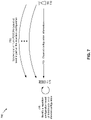
- FIG. 7 is a diagram illustrating an example 700 of repetition configuration determination, in accordance with various aspects of the present disclosure. As shown in FIG. 7 , example 700 includes a BS 110 and a UE 120 .
- UE 120 may receive, from BS 110 , channel configuration information for a physical downlink control channel (PDCCH). For example, UE 120 may receive a radio resource control (RRC) message identifying a CORESET for the PDCCH, a search space for the PDCCH, an aggregation level for the PDCCH, and/or the like. Additionally, or alternatively, UE 120 may receive a downlink control information (DCI) message associated with the PDCCH (e.g., a DCI associated with a particular format and identifying a resource allocation for the PDCCH).
- RRC radio resource control
- DCI downlink control information
- UE 120 may identify a repetition configuration based at least in part on a channel configuration. For example, based at least in part on stored mapping information, UE 120 may determine that a particular CORESET (e.g., CORESET 0 , CORESET 1 , and/or the like) is associated with a particular quantity of transmissions of the PDCCH. In this case, UE 120 may determine that the particular CORESET is associated with the particular quantity of repetitions based at least in part on stored information identifying a mapping of a plurality of CORESETs to a plurality of quantities of repetitions.
- a particular CORESET e.g., CORESET 0 , CORESET 1 , and/or the like
- UE 120 may determine that a particular search space (e.g., associated with a particular periodicity) is associated with indicating a particular quantity of repetitions. Additionally, or alternatively, UE 120 may determine that a particular aggregation level is associated with indicating a particular quantity of repetitions. Additionally, or alternatively, UE 120 may determine that a particular DCI format of a received DCI is associated with indicating a particular quantity of repetitions.
- a particular search space e.g., associated with a particular periodicity
- UE 120 may determine that a particular aggregation level is associated with indicating a particular quantity of repetitions.
- UE 120 may determine that a particular DCI format of a received DCI is associated with indicating a particular quantity of repetitions.
- UE 120 may monitor for, and may receive one or more PDCCHs. For example, UE 120 may determine to receive a single transmission of the PDCCH, a plurality of transmissions of the PDCCH, and/or the like. In this case, UE 120 may reconstruct the PDCCH based at least in part on the one or more PDCCHs. For example, UE 120 may combine information associated with a plurality of transmissions of the PDCCH to reconstruct the PDCCH under poor channel conditions. In this way, BS 110 may signal, and UE 120 may determine a quantity of repetitions of a PDCCH, thereby enabling dynamic reconfiguration of the quantity of repetitions based at least in part on channel conditions of a network.
- FIG. 7 is provided as an example. Other examples are possible and may differ from what was described with respect to FIG. 7 .
- FIGS. 8A and 8B are diagrams illustrating an example 800 of repetition configuration determination, in accordance with various aspects of the present disclosure. As shown in FIG. 8A , example 800 includes a BS 110 and a UE 120 .
- UE 120 may receive one or more PDCCHs from BS 110 .
- UE 120 may receive a first PDCCH associated with a first CORESET and a second PDCCH associated with a second CORESET.
- UE 120 may identify a repetition configuration based at least in part on a channel configuration. For example, based at least in part on stored mapping information, UE 120 may determine that a first physical downlink shared channel (PDSCH) associated with the first PDCCH is associated with a first aggregation level based at least in part on the first PDCCH being associated with the first CORESET. Similarly, UE 120 may determine that a second PDSCH associated with the second PDCCH is associated with a second aggregation level based at least in part on the second PDCCH being associated with the second CORESET.
- PDSCH physical downlink shared channel
- UE 120 may determine a PDSCH repetition configuration based at least in part on a PDCCH repetition configuration. For example, UE 120 may map a particular quantity of repetitions of a PDCCH to a particular aggregation level for the PDSCH. Similarly, UE 120 may map a particular PDSCH aggregation level to a particular PDCCH configuration (e.g., a particular PDCCH CORESET, a particular PDCCH repetition configuration, and/or the like) to enable a PDSCH to be used to signal for a subsequent PDCCH. In some aspects, UE 120 may determine a PDSCH repetition configuration based at least in part on a received DCI, a received media access control (MAC) control element (CE), a received transmission configuration indicator (TCI), and/or the like.
- MAC media access control
- CE received transmission configuration indicator
- UE 120 may monitor for, and may receive one or more PDSCHs from the BS 110 based at least in part on the repetition configuration. For example, UE 120 may receive the first PDSCH associated with the first aggregation level in a single slot based at least in part on the first aggregation level. Similarly, UE 120 may receive a plurality of slots of the second PDSCH associated with the second aggregation level based at least in part on the second aggregation level. In this case, UE 120 may reconstruct the PDSCH based at least in part on receiving the PDSCH. For example, UE 120 may combine the plurality of slots of the second PDSCH to reconstruct the second PDSCH. In this way, BS 110 may signal, and UE 120 may determine a repetition configuration relating to an aggregation level for a PDSCH.
- FIGS. 8A and 8B are provided as an example. Other examples are possible and may differ from what was described with respect to FIGS. 8A and 8B .
- FIG. 9 is a diagram illustrating an example process 900 performed, for example, by a UE, in accordance with various aspects of the present disclosure.
- Example process 900 is an example where a UE (e.g., UE 120 ) performs repetition configuration determination.
- a UE e.g., UE 120
- process 900 may include receiving information identifying a channel configuration associated with a downlink channel (block 910 ).
- the UE e.g., using antenna 252 , DEMOD 254 , MIMO detector 256 , receive processor 258 , controller/processor 280 , and/or the like
- process 900 may include identifying a repetition configuration for the downlink channel based at least in part on the channel configuration (block 920 ).
- the UE e.g., using controller/processor 280 and/or the like
- process 900 may include monitoring for the downlink channel in accordance with the repetition configuration based at least in part on identifying the repetition configuration (block 930 ).
- the UE e.g., using antenna 252 , DEMOD 254 , MIMO detector 256 , receive processor 258 , controller/processor 280 , and/or the like
- Process 900 may include additional aspects, such as any single aspect or any combination of aspects described below and/or in connection with one or more other processes described elsewhere herein.
- the channel configuration identifies a parameter, and the parameter is at least one of: a core resource set parameter, a search space parameter, a downlink control information format parameter, or an aggregation level parameter.
- the channel configuration identifies a plurality of parameters, and the plurality of parameters includes at least two of: a core resource set parameter, a search space parameter, a downlink control information format parameter, or an aggregation level parameter.
- the repetition configuration corresponds to a particular quantity of transmissions of the downlink channel, and monitoring for the particular quantity of transmissions of the downlink channel.
- the UE is configured to receive the information identifying the channel configuration using radio resource control signaling.
- the downlink channel is a physical downlink control channel and the repetition configuration is a quantity of transmissions of the physical downlink control channel.
- the downlink channel is a physical downlink shared channel and the repetition configuration is an aggregation level configuration identifying a quantity of slots for the physical downlink shared channel.
- the channel configuration is a particular physical downlink control channel of a plurality of physical downlink control channels, and wherein the UE is configured to store a mapping of the particular physical downlink control channel to a particular set of physical downlink shared channels of a plurality of physical downlink shared channels.
- the UE is configured to store a mapping of a physical downlink control channel repetition configuration to a physical downlink shared channel slot aggregation configuration.
- the UE is configured to store a mapping a physical downlink shared channel slot aggregation configuration to a physical downlink control channel channel configuration.
- the UE is configured to determine the repetition configuration based at least in part on at least one of: a radio resource control message, a downlink control information message, a media access control control element message, or a transmission configuration indicator.
- process 900 may include additional blocks, fewer blocks, different blocks, or differently arranged blocks than those depicted in FIG. 9 . Additionally, or alternatively, two or more of the blocks of process 900 may be performed in parallel.
- the term component is intended to be broadly construed as hardware, firmware, or a combination of hardware and software.
- a processor is implemented in hardware, firmware, or a combination of hardware and software.
- satisfying a threshold may refer to a value being greater than the threshold, greater than or equal to the threshold, less than the threshold, less than or equal to the threshold, equal to the threshold, not equal to the threshold, and/or the like.
- “at least one of: a, b, or c” is intended to cover a, b, c, a-b, a-c, b-c, and a-b-c, as well as any combination with multiples of the same element (e.g., a-a, a-a-a, a-a-b, a-a-c, a-b-b, a-c-c, b-b, b-b-b, b-b-c, c-c, and c-c-c or any other ordering of a, b, and c).
Landscapes
- Engineering & Computer Science (AREA)
- Signal Processing (AREA)
- Computer Networks & Wireless Communication (AREA)
- Computer Security & Cryptography (AREA)
- Mobile Radio Communication Systems (AREA)
Abstract
Description
Claims (30)
Priority Applications (2)
| Application Number | Priority Date | Filing Date | Title |
|---|---|---|---|
| US16/141,567 US11425702B2 (en) | 2018-08-06 | 2018-09-25 | Repetition configuration determination |
| PCT/US2019/044168 WO2020033191A1 (en) | 2018-08-06 | 2019-07-30 | Repetition configuration determination |
Applications Claiming Priority (3)
| Application Number | Priority Date | Filing Date | Title |
|---|---|---|---|
| US201862715205P | 2018-08-06 | 2018-08-06 | |
| US201862715633P | 2018-08-07 | 2018-08-07 | |
| US16/141,567 US11425702B2 (en) | 2018-08-06 | 2018-09-25 | Repetition configuration determination |
Publications (2)
| Publication Number | Publication Date |
|---|---|
| US20200045676A1 US20200045676A1 (en) | 2020-02-06 |
| US11425702B2 true US11425702B2 (en) | 2022-08-23 |
Family
ID=69229267
Family Applications (1)
| Application Number | Title | Priority Date | Filing Date |
|---|---|---|---|
| US16/141,567 Active 2039-02-05 US11425702B2 (en) | 2018-08-06 | 2018-09-25 | Repetition configuration determination |
Country Status (2)
| Country | Link |
|---|---|
| US (1) | US11425702B2 (en) |
| WO (1) | WO2020033191A1 (en) |
Families Citing this family (3)
| Publication number | Priority date | Publication date | Assignee | Title |
|---|---|---|---|---|
| WO2020032779A1 (en) * | 2018-08-10 | 2020-02-13 | 엘지전자 주식회사 | Method for transmitting and receiving harq information in wireless communication system, and device therefor |
| US20200107319A1 (en) * | 2018-09-28 | 2020-04-02 | Lenovo (Singapore) Pte. Ltd. | Method and apparatus for generating a csi report |
| WO2022083770A1 (en) * | 2020-10-23 | 2022-04-28 | FG Innovation Company Limited | Method of monitoring physical downlink control channel and related device |
Citations (11)
| Publication number | Priority date | Publication date | Assignee | Title |
|---|---|---|---|---|
| WO2015057028A1 (en) | 2013-10-17 | 2015-04-23 | Lg Electronics Inc. | The method and apparatus for wireless communication |
| WO2016159656A1 (en) | 2015-03-30 | 2016-10-06 | Lg Electronics Inc. | Method and apparatus for designing downlink control information in wireless communication system |
| WO2016162565A1 (en) | 2015-04-10 | 2016-10-13 | Telefonaktiebolaget Lm Ericsson (Publ) | Lc-pdcch repetition level selection for mtc devices |
| US20170013626A1 (en) * | 2014-03-21 | 2017-01-12 | Huawei Technologies Co., Ltd. | Method for enhanced transmission of control information, user equipment, base station, and communications system |
| US20170230780A1 (en) * | 2016-02-05 | 2017-08-10 | Qualcomm Incorporated | Adaptive radio link monitoring |
| EP3291474A1 (en) | 2015-04-29 | 2018-03-07 | LG Electronics Inc. | Method and lc apparatus for receiving downlink control channel |
| US20190150142A1 (en) * | 2017-11-13 | 2019-05-16 | Asustek Computer Inc. | Method and apparatus for indicating time domain resource allocation of data transmission in a wireless communication system |
| US20190182807A1 (en) * | 2018-02-16 | 2019-06-13 | Intel Corporation | Reliability mechanisms for physical downlink control channel (pdcch) transmissions in new radio (nr) systems |
| US20200022144A1 (en) * | 2018-07-09 | 2020-01-16 | Samsung Electronics Co., Ltd. | Overhead reduction and reliability enhancements for dl control signaling |
| US20200145165A1 (en) * | 2017-07-14 | 2020-05-07 | Huawei Technologies Co., Ltd. | Communication Method and Device |
| US20200154467A1 (en) * | 2017-06-15 | 2020-05-14 | Huawei Technologies Co., Ltd. | Method and Devices for Multiple Transmit Receive Point Cooperation for Reliable Communication |
-
2018
- 2018-09-25 US US16/141,567 patent/US11425702B2/en active Active
-
2019
- 2019-07-30 WO PCT/US2019/044168 patent/WO2020033191A1/en active Application Filing
Patent Citations (12)
| Publication number | Priority date | Publication date | Assignee | Title |
|---|---|---|---|---|
| WO2015057028A1 (en) | 2013-10-17 | 2015-04-23 | Lg Electronics Inc. | The method and apparatus for wireless communication |
| US20170013626A1 (en) * | 2014-03-21 | 2017-01-12 | Huawei Technologies Co., Ltd. | Method for enhanced transmission of control information, user equipment, base station, and communications system |
| WO2016159656A1 (en) | 2015-03-30 | 2016-10-06 | Lg Electronics Inc. | Method and apparatus for designing downlink control information in wireless communication system |
| WO2016162565A1 (en) | 2015-04-10 | 2016-10-13 | Telefonaktiebolaget Lm Ericsson (Publ) | Lc-pdcch repetition level selection for mtc devices |
| US20180198677A1 (en) * | 2015-04-10 | 2018-07-12 | Telefonaktiebolaget Lm Ericsson (Publ) | Configuration of a User Equipment; Aggregation Level Configuration of Physical Downlink Control Channel for Machine Type Communications |
| EP3291474A1 (en) | 2015-04-29 | 2018-03-07 | LG Electronics Inc. | Method and lc apparatus for receiving downlink control channel |
| US20170230780A1 (en) * | 2016-02-05 | 2017-08-10 | Qualcomm Incorporated | Adaptive radio link monitoring |
| US20200154467A1 (en) * | 2017-06-15 | 2020-05-14 | Huawei Technologies Co., Ltd. | Method and Devices for Multiple Transmit Receive Point Cooperation for Reliable Communication |
| US20200145165A1 (en) * | 2017-07-14 | 2020-05-07 | Huawei Technologies Co., Ltd. | Communication Method and Device |
| US20190150142A1 (en) * | 2017-11-13 | 2019-05-16 | Asustek Computer Inc. | Method and apparatus for indicating time domain resource allocation of data transmission in a wireless communication system |
| US20190182807A1 (en) * | 2018-02-16 | 2019-06-13 | Intel Corporation | Reliability mechanisms for physical downlink control channel (pdcch) transmissions in new radio (nr) systems |
| US20200022144A1 (en) * | 2018-07-09 | 2020-01-16 | Samsung Electronics Co., Ltd. | Overhead reduction and reliability enhancements for dl control signaling |
Non-Patent Citations (5)
| Title |
|---|
| International Search Report and Written Opinion—PCT/US2019/044168—ISA/EPO—dated Oct. 25, 2019. |
| SEQUANS COMMUNICATIONS: "On PDCCH repetition for NR URLLC", 3GPP DRAFT; R1-1806958 - ON PDCCH REPETITION FOR NR URLLC, 3RD GENERATION PARTNERSHIP PROJECT (3GPP), MOBILE COMPETENCE CENTRE ; 650, ROUTE DES LUCIOLES ; F-06921 SOPHIA-ANTIPOLIS CEDEX ; FRANCE, vol. RAN WG1, no. Busan, Korea; 20180521 - 20180525, R1-1806958 - On PDCCH repetition for NR URLLC, 11 May 2018 (2018-05-11), Mobile Competence Centre ; 650, route des Lucioles ; F-06921 Sophia-Antipolis Cedex ; France , XP051462094 |
| Sequans Communications: "On PDCCH Repetition for NR URLLC," 3GPP Draft; R1-1806958—On PDCCH Repetition for NR URLLC, 3rd Generation Partnership Project (3GPP), Mobile Competence Centre; 650, Route Des Lucioles; F-06921 Sophia-Antipolis Cedex; France, vol. RAN WG1, No. Busan, Korea; May 21, 2018-May 25, 2018, May 11, 2018, XP051462094, 6 pages, Retrieved from the Internet: URL: http://www.3gpp.org/ftp/tsg%5Fran/WG1%5FRL1/TSGR1%5F93/Docs [retrieved on May 11, 2018] section 2.3. |
| VIVO: "Remaining issues on PDCCH CORESET", 3GPP DRAFT; R1-1806055_REMAINING ISSUES ON PDCCH CORESET, 3RD GENERATION PARTNERSHIP PROJECT (3GPP), MOBILE COMPETENCE CENTRE ; 650, ROUTE DES LUCIOLES ; F-06921 SOPHIA-ANTIPOLIS CEDEX ; FRANCE, R1-1806055_Remaining issues on PDCCH CORESET, 12 May 2018 (2018-05-12), Mobile Competence Centre ; 650, route des Lucioles ; F-06921 Sophia-Antipolis Cedex ; France , pages 1 - 4, XP051462320 |
| VIVO: "Remaining Issue on PDCCH Coreset," 3GPP Draft; R1-1806055_Remaining Issues on PDCCH Coreset, 3rd Generation Partnership Project (3GPP), Mobile Competence Centre; 650, Route Des Lucioles; F-06921 Sophia-Antipolis Cedex; France, vol. RAN WG1, No. Busan, Korea; May 21, 2018-May 25, 2018, May 12, 2018, XP051462320, 4 pages, Retrieved from the Internet: URL: http://www.3gpp.org/ftp/tsg%5Fran/WG1%5FRL1/TSGR1%5F93/Docs [retrieved on May 12, 2018] section 2.1. |
Also Published As
| Publication number | Publication date |
|---|---|
| WO2020033191A1 (en) | 2020-02-13 |
| US20200045676A1 (en) | 2020-02-06 |
Similar Documents
| Publication | Publication Date | Title |
|---|---|---|
| US11350416B2 (en) | Physical uplink control channel repetition configuration | |
| US11950212B2 (en) | Timing advance signaling for multi-transmit receive point operation | |
| US11234253B2 (en) | Transmit parameter control | |
| US20190387532A1 (en) | System information block transmission scheduling | |
| US11516814B2 (en) | Beam selection for communication in a multi-transmit-receive point deployment | |
| US11290174B2 (en) | Beam selection for communication in a multi-transmit-receive point deployment | |
| US11974296B2 (en) | Transmission configuration indicator determination for mixed mode operation | |
| US10785656B2 (en) | Bandwidth part switch management | |
| US20200154465A1 (en) | Quasi co-location relation configuration for periodic channel state information reference signals | |
| US11265854B2 (en) | Collision handling for physical uplink channel repetition | |
| US11095356B2 (en) | Secondary cell recovery for secondary cell groups | |
| US11166265B2 (en) | Downlink control channel beam sweeping | |
| US10966231B2 (en) | Configuring aggregation level and physical downlink control channel candidates at a user equipment | |
| US11265890B2 (en) | Resource rate matching for remote interference management | |
| US11425702B2 (en) | Repetition configuration determination | |
| US20220330155A1 (en) | Secondary cell dormancy using dormancy profile | |
| US10886995B2 (en) | Beam management signaling | |
| US11497053B2 (en) | Collision management | |
| US20210028900A1 (en) | Tracking reference signal configuration | |
| US11716686B2 (en) | Cross-cell group wake up messaging | |
| US11212770B2 (en) | Techniques for configuring paging cycles | |
| US11044064B2 (en) | Determining hybrid automatic repeat request (HARQ) processes for multi-transmit receive point (TRP) | |
| US11979852B2 (en) | Paging indication for communicating a paging control channel | |
| WO2019200608A1 (en) | Techniques and apparatuses for numerology signaling |
Legal Events
| Date | Code | Title | Description |
|---|---|---|---|
| FEPP | Fee payment procedure |
Free format text: ENTITY STATUS SET TO UNDISCOUNTED (ORIGINAL EVENT CODE: BIG.); ENTITY STATUS OF PATENT OWNER: LARGE ENTITY |
|
| AS | Assignment |
Owner name: QUALCOMM INCORPORATED, CALIFORNIA Free format text: ASSIGNMENT OF ASSIGNORS INTEREST;ASSIGNORS:RYU, JUNG;JOHN WILSON, MAKESH PRAVIN;LUO, TAO;AND OTHERS;SIGNING DATES FROM 20190128 TO 20190314;REEL/FRAME:048636/0984 |
|
| STPP | Information on status: patent application and granting procedure in general |
Free format text: NON FINAL ACTION MAILED |
|
| STPP | Information on status: patent application and granting procedure in general |
Free format text: RESPONSE TO NON-FINAL OFFICE ACTION ENTERED AND FORWARDED TO EXAMINER |
|
| STPP | Information on status: patent application and granting procedure in general |
Free format text: RESPONSE AFTER FINAL ACTION FORWARDED TO EXAMINER |
|
| STPP | Information on status: patent application and granting procedure in general |
Free format text: NON FINAL ACTION MAILED |
|
| STPP | Information on status: patent application and granting procedure in general |
Free format text: RESPONSE TO NON-FINAL OFFICE ACTION ENTERED AND FORWARDED TO EXAMINER |
|
| STPP | Information on status: patent application and granting procedure in general |
Free format text: FINAL REJECTION MAILED |
|
| STPP | Information on status: patent application and granting procedure in general |
Free format text: RESPONSE AFTER FINAL ACTION FORWARDED TO EXAMINER |
|
| STPP | Information on status: patent application and granting procedure in general |
Free format text: DOCKETED NEW CASE - READY FOR EXAMINATION |
|
| STPP | Information on status: patent application and granting procedure in general |
Free format text: NON FINAL ACTION MAILED |
|
| STPP | Information on status: patent application and granting procedure in general |
Free format text: RESPONSE TO NON-FINAL OFFICE ACTION ENTERED AND FORWARDED TO EXAMINER |
|
| STPP | Information on status: patent application and granting procedure in general |
Free format text: NOTICE OF ALLOWANCE MAILED -- APPLICATION RECEIVED IN OFFICE OF PUBLICATIONS |
|
| STPP | Information on status: patent application and granting procedure in general |
Free format text: PUBLICATIONS -- ISSUE FEE PAYMENT VERIFIED |
|
| STCF | Information on status: patent grant |
Free format text: PATENTED CASE |