US11411331B2 - Hybrid type wire-to-wire connector structure and power supply device having the same - Google Patents
Hybrid type wire-to-wire connector structure and power supply device having the same Download PDFInfo
- Publication number
- US11411331B2 US11411331B2 US16/441,845 US201916441845A US11411331B2 US 11411331 B2 US11411331 B2 US 11411331B2 US 201916441845 A US201916441845 A US 201916441845A US 11411331 B2 US11411331 B2 US 11411331B2
- Authority
- US
- United States
- Prior art keywords
- power
- signal
- seat
- power supply
- connecting seat
- Prior art date
- Legal status (The legal status is an assumption and is not a legal conclusion. Google has not performed a legal analysis and makes no representation as to the accuracy of the status listed.)
- Active, expires
Links
Images


Classifications
-
- H—ELECTRICITY
- H01—ELECTRIC ELEMENTS
- H01R—ELECTRICALLY-CONDUCTIVE CONNECTIONS; STRUCTURAL ASSOCIATIONS OF A PLURALITY OF MUTUALLY-INSULATED ELECTRICAL CONNECTING ELEMENTS; COUPLING DEVICES; CURRENT COLLECTORS
- H01R31/00—Coupling parts supported only by co-operation with counterpart
- H01R31/06—Intermediate parts for linking two coupling parts, e.g. adapter
-
- H—ELECTRICITY
- H01—ELECTRIC ELEMENTS
- H01R—ELECTRICALLY-CONDUCTIVE CONNECTIONS; STRUCTURAL ASSOCIATIONS OF A PLURALITY OF MUTUALLY-INSULATED ELECTRICAL CONNECTING ELEMENTS; COUPLING DEVICES; CURRENT COLLECTORS
- H01R13/00—Details of coupling devices of the kinds covered by groups H01R12/70 or H01R24/00 - H01R33/00
- H01R13/73—Means for mounting coupling parts to apparatus or structures, e.g. to a wall
- H01R13/74—Means for mounting coupling parts in openings of a panel
- H01R13/741—Means for mounting coupling parts in openings of a panel using snap fastening means
-
- H—ELECTRICITY
- H01—ELECTRIC ELEMENTS
- H01R—ELECTRICALLY-CONDUCTIVE CONNECTIONS; STRUCTURAL ASSOCIATIONS OF A PLURALITY OF MUTUALLY-INSULATED ELECTRICAL CONNECTING ELEMENTS; COUPLING DEVICES; CURRENT COLLECTORS
- H01R12/00—Structural associations of a plurality of mutually-insulated electrical connecting elements, specially adapted for printed circuits, e.g. printed circuit boards [PCB], flat or ribbon cables, or like generally planar structures, e.g. terminal strips, terminal blocks; Coupling devices specially adapted for printed circuits, flat or ribbon cables, or like generally planar structures; Terminals specially adapted for contact with, or insertion into, printed circuits, flat or ribbon cables, or like generally planar structures
- H01R12/70—Coupling devices
- H01R12/7005—Guiding, mounting, polarizing or locking means; Extractors
-
- G—PHYSICS
- G06—COMPUTING; CALCULATING OR COUNTING
- G06F—ELECTRIC DIGITAL DATA PROCESSING
- G06F1/00—Details not covered by groups G06F3/00 - G06F13/00 and G06F21/00
- G06F1/16—Constructional details or arrangements
- G06F1/18—Packaging or power distribution
- G06F1/183—Internal mounting support structures, e.g. for printed circuit boards, internal connecting means
- G06F1/188—Mounting of power supply units
-
- G—PHYSICS
- G06—COMPUTING; CALCULATING OR COUNTING
- G06F—ELECTRIC DIGITAL DATA PROCESSING
- G06F1/00—Details not covered by groups G06F3/00 - G06F13/00 and G06F21/00
- G06F1/26—Power supply means, e.g. regulation thereof
-
- H—ELECTRICITY
- H01—ELECTRIC ELEMENTS
- H01R—ELECTRICALLY-CONDUCTIVE CONNECTIONS; STRUCTURAL ASSOCIATIONS OF A PLURALITY OF MUTUALLY-INSULATED ELECTRICAL CONNECTING ELEMENTS; COUPLING DEVICES; CURRENT COLLECTORS
- H01R12/00—Structural associations of a plurality of mutually-insulated electrical connecting elements, specially adapted for printed circuits, e.g. printed circuit boards [PCB], flat or ribbon cables, or like generally planar structures, e.g. terminal strips, terminal blocks; Coupling devices specially adapted for printed circuits, flat or ribbon cables, or like generally planar structures; Terminals specially adapted for contact with, or insertion into, printed circuits, flat or ribbon cables, or like generally planar structures
- H01R12/70—Coupling devices
- H01R12/71—Coupling devices for rigid printing circuits or like structures
- H01R12/712—Coupling devices for rigid printing circuits or like structures co-operating with the surface of the printed circuit or with a coupling device exclusively provided on the surface of the printed circuit
- H01R12/716—Coupling device provided on the PCB
-
- H—ELECTRICITY
- H01—ELECTRIC ELEMENTS
- H01R—ELECTRICALLY-CONDUCTIVE CONNECTIONS; STRUCTURAL ASSOCIATIONS OF A PLURALITY OF MUTUALLY-INSULATED ELECTRICAL CONNECTING ELEMENTS; COUPLING DEVICES; CURRENT COLLECTORS
- H01R13/00—Details of coupling devices of the kinds covered by groups H01R12/70 or H01R24/00 - H01R33/00
- H01R13/62—Means for facilitating engagement or disengagement of coupling parts or for holding them in engagement
- H01R13/627—Snap or like fastening
- H01R13/6271—Latching means integral with the housing
- H01R13/6272—Latching means integral with the housing comprising a single latching arm
-
- H—ELECTRICITY
- H01—ELECTRIC ELEMENTS
- H01R—ELECTRICALLY-CONDUCTIVE CONNECTIONS; STRUCTURAL ASSOCIATIONS OF A PLURALITY OF MUTUALLY-INSULATED ELECTRICAL CONNECTING ELEMENTS; COUPLING DEVICES; CURRENT COLLECTORS
- H01R13/00—Details of coupling devices of the kinds covered by groups H01R12/70 or H01R24/00 - H01R33/00
- H01R13/73—Means for mounting coupling parts to apparatus or structures, e.g. to a wall
- H01R13/74—Means for mounting coupling parts in openings of a panel
-
- H—ELECTRICITY
- H01—ELECTRIC ELEMENTS
- H01R—ELECTRICALLY-CONDUCTIVE CONNECTIONS; STRUCTURAL ASSOCIATIONS OF A PLURALITY OF MUTUALLY-INSULATED ELECTRICAL CONNECTING ELEMENTS; COUPLING DEVICES; CURRENT COLLECTORS
- H01R24/00—Two-part coupling devices, or either of their cooperating parts, characterised by their overall structure
- H01R24/005—Two-part coupling devices, or either of their cooperating parts, characterised by their overall structure requiring successive relative motions to complete the coupling, e.g. bayonet type
-
- H—ELECTRICITY
- H01—ELECTRIC ELEMENTS
- H01R—ELECTRICALLY-CONDUCTIVE CONNECTIONS; STRUCTURAL ASSOCIATIONS OF A PLURALITY OF MUTUALLY-INSULATED ELECTRICAL CONNECTING ELEMENTS; COUPLING DEVICES; CURRENT COLLECTORS
- H01R27/00—Coupling parts adapted for co-operation with two or more dissimilar counterparts
- H01R27/02—Coupling parts adapted for co-operation with two or more dissimilar counterparts for simultaneous co-operation with two or more dissimilar counterparts
-
- H—ELECTRICITY
- H01—ELECTRIC ELEMENTS
- H01R—ELECTRICALLY-CONDUCTIVE CONNECTIONS; STRUCTURAL ASSOCIATIONS OF A PLURALITY OF MUTUALLY-INSULATED ELECTRICAL CONNECTING ELEMENTS; COUPLING DEVICES; CURRENT COLLECTORS
- H01R2107/00—Four or more poles
Definitions
- the present invention generally relates to connector structures and, in particular to a wire-to-wire connector structure.
- the wires of the power connector and the signal connector are tied to the housing of the power supply device by wire harnesses for the purpose of cable routing.
- problems such as different wire lengths or long assembly time exist. Therefore, the connection way needs to be improved.
- the Inventor proposes the present invention based on his expert knowledge and elaborate researches in order to solve the problems of prior art.
- an object of the present invention is to provide a hybrid type wire-to-wire connector structure to reduce labor time, process and material costs, and the yield rate and efficiency of production will be improved.
- the present invention provides a hybrid type wire-to-wire connector structure for assembling in an accommodating opening of a housing including a connecting seat and an adapter seat.
- the connecting seat has a signal line terminal and a power line terminal.
- One end of the connecting seat is extended with an annular rib corresponding to the accommodating opening, and the connecting seat is disposed in the accommodating opening through the annular rib.
- the adapter seat has a signal conduction end with respect to the signal line terminal and a power conduction end with respect to the power line terminal.
- the adapter seat is extended with a hook corresponding to the annular rib, wherein the connecting seat and the adapter seat are combined through the signal conduction end inserted in the signal line terminal, the power conduction end inserted in the power line terminal, and the hook clamped with the annular rib.
- the present invention provides a power supply device comprising a power supply housing, a circuit board, and a hybrid type wire-to-wire connector structure.
- the power supply housing has an accommodating space and an accommodating opening.
- the circuit board is disposed in the accommodating space.
- the hybrid type wire-to-wire connector structure comprises a connecting seat, a conducting seat, a plurality of signal wires, a plurality of power wires, and an adapter seat.
- the connecting seat has a plurality of signal terminal slots and a plurality of power terminal slots.
- One end of the connecting seat is extended with an annular rib corresponding to the accommodating opening, and the connecting seat is disposed in the accommodating opening through the annular rib.
- the conducting seat is inserted on the circuit board, and the conducting seat includes a plurality of signal holes and a plurality of power holes. One end of each signal wire is inserted in the signal hole and the other end is connected to the signal terminal slot. One end of each power wire is inserted in the power hole and the other end is connected to the power terminal slot.
- the adapter seat has a plurality of signal conduction columns with respect to the signal terminal slots and a plurality of power conduction columns with respect to the power terminal slots.
- the adapter seat is extended with a hook corresponding to the annular rib, wherein the connecting seat and the adapter seat are combined through the signal conduction columns inserted in the signal terminal slots, the power conduction columns inserted in the power terminal slots, and the hook clamped with the annular rib.
- the hybrid type wire-to-wire connector structure of the present invention has provided the connecting seat having a signal line terminal and a power line terminal, the adapter seat having a signal conduction end and a power conduction end, and the conducting seat having signal holes and power holes so as to integrate the connections of power and signal, and that has advantages of simplifying the assembly and reducing labor time, process schedule and material costs, thus the yield of production and efficiency will be improved.
- the connecting seat of the present invention is provided as an extension joint, and it can be mounted on the circuit board or fixed on the housing of power supply.
- the connecting seat of the present invention has an annular rib extended from a periphery thereof, and the adapter seat has extended with a hook with respect to the annular rib to be positioned on the connecting seat.
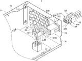
- FIG. 1 and FIG. 2 depict perspective views of two sides of power supply device of the present invention
- FIG. 3 depict a combination schematic view of the adapter seat and housing of the present invention
- FIG. 4 depict a combination schematic view of the hybrid type wire-to-wire connector structure and the circuit board of the present invention
- FIG. 5 depict a combination schematic view of the adapter seat and the connecting seat of the hybrid type wire-to-wire connector structure
- FIG. 6 depict a combination schematic view of the connecting seat and the adapter seat of the present invention.
- FIG. 7 depict a combination schematic view of the conducting seat and the electrical connector of the present invention.
- the power supply device 1 of the present invention includes a power supply housing 10 , a circuit board 20 , and a hybrid type wire-to-wire connector structure 30 .
- the circuit board 20 is displaced in the power supply housing 10 .
- the hybrid type wire-to-wire connector structure 30 is assembled with the power supply housing 10 and electrically connected with the circuit board 20 for connecting an external electronic device.
- other electronic components in the power supply housing 10 are customary and will not be described later. More detail descriptions of the power supply device 1 and the hybrid type wire-to-wire connector structure 30 are as follows.
- FIG. 3 to FIG. 5 they depict a combination schematic view of the adapter seat and the housing of the present invention, a combination schematic view of the hybrid type wire-to-wire connector structure and the circuit board of the present invention, and a combination schematic view of the adapter seat and the connecting seat of the hybrid type wire-to-wire connector structure of the present invention.
- the power supply housing 10 has an accommodating space 11 and an accommodating opening 12 .
- the circuit board 20 is disposed in the accommodating space 11 , and the circuit board 20 is provided with an electrical connector 21 .
- the hybrid wire-to-wire connector structure 30 is assembled in the accommodating opening 12 of the power supply housing 10 for connecting with the electrical connector 21 and connected to an external electronic device.
- the hybrid type wire-to-wire connector structure 30 comprises a connecting seat 31 and an adapter seat 32 .
- the connecting seat 31 has a signal line terminal 311 and a power line terminal 312 .
- the signal line terminal 311 includes a plurality of signal terminal slots 3110 ;
- the power line terminal 312 includes a plurality of power terminal slots 3120 .
- one end of the connecting seat 31 is extended with an annular rib 313 corresponding to the accommodating opening 12 , and the connecting seat 31 is disposed in the accommodating opening 12 through the annular rib 313 .
- the opening profile of the accommodating opening 12 is provided corresponding to the contour of the connecting seat 31 .
- the connecting seat 31 is formed with a pair of elastic arms 314 on opposite two outer sides.
- the pair of elastic arms 314 are elastically compressed slightly when passing the accommodating opening 12 and will return to the original position after passing through the accommodating opening 12 . Thereby, when the adapter seat 32 is inserted with respect to the connecting seat 31 , the connecting seat 31 will not be loosen or detached under an external force.
- the adapter seat 32 has a signal conduction end 321 with respect to the signal line terminal 311 and a power conduction end 322 with respect to the power line terminal 312 .
- the signal conduction end 321 includes a plurality of signal conduction columns 3210
- the power conduction end 322 includes a plurality of power conduction columns 3220 .
- the signal terminal slots 3110 and the power terminal slots 3120 are square slots. Besides, the depths of the signal terminal slots 3110 are greater than the depths of the power terminal slots 3120 ; therefore, the lengths of the signal conduction columns 3210 are greater than the lengths of the power conduction columns 3220 . Thereby, the misinsertion can be prevented, and to have a foolproof effect, and the purpose of saving material can be achieved.
- the adapter seat 32 can be inserted into the connecting seat 31 positively without misinsertion.
- the adapter seat 32 are extended with a hook 323 corresponding to the annular rib 313 .
- the connecting seat 31 and the adapter seat 32 are combined through the signal conduction columns 321 inserted in the signal terminal slots 311 , the power conduction columns 322 inserted in the power terminal slots 312 , and the hook 323 clamped with the annular rib 313 .
- one end of the annular rib 313 has a notch 3130 corresponding to the hook 323 , and the hook 323 passes through the notch 3130 to be clamped in the accommodating opening 12 .
- the hybrid type wire-to-wire connector structure 30 further includes a conducting seat 33 , a plurality of signal wires 34 and a plurality of power wires 35 .
- the conducting seat 33 includes a plurality of signal holes 331 and a plurality of power holes 332 .
- each of the signal wires 34 has one end inserted in the signal hole 331 and the other end connected to the signal terminal slot 3110 ; and further, each of the power wires 35 has one end inserted in the power hole 332 and the other end connected to the power terminal slot 3120 .
- the conducting seat 33 is connected to the connecting seat 31 through the signal wires 34 and the power wires 35 , and it can be further connected to the electrical connector 21 of the circuit board 20 .
- each of the power terminal slots 312 , the power conduction columns 322 and the power holes 332 can accommodate at least two power wires with a wire diameter of 16 AWG to increase the convenience of use.
Abstract
Description
Claims (5)
Applications Claiming Priority (3)
| Application Number | Priority Date | Filing Date | Title |
|---|---|---|---|
| TW108115263 | 2019-05-02 | ||
| TW108115263A TWI713268B (en) | 2019-05-02 | 2019-05-02 | Hybrid type wire-to-wire connector structure and power supply device having the same |
| TW10811526.3 | 2019-05-02 |
Publications (2)
| Publication Number | Publication Date |
|---|---|
| US20200350713A1 US20200350713A1 (en) | 2020-11-05 |
| US11411331B2 true US11411331B2 (en) | 2022-08-09 |
Family
ID=73016742
Family Applications (1)
| Application Number | Title | Priority Date | Filing Date |
|---|---|---|---|
| US16/441,845 Active 2041-04-13 US11411331B2 (en) | 2019-05-02 | 2019-06-14 | Hybrid type wire-to-wire connector structure and power supply device having the same |
Country Status (3)
| Country | Link |
|---|---|
| US (1) | US11411331B2 (en) |
| CN (1) | CN111883957B (en) |
| TW (1) | TWI713268B (en) |
Citations (59)
| Publication number | Priority date | Publication date | Assignee | Title |
|---|---|---|---|---|
| US3523269A (en) * | 1968-03-08 | 1970-08-04 | Essex International Inc | Panel locking terminal connector block |
| US3573716A (en) * | 1968-12-26 | 1971-04-06 | Amp Inc | Connector housing having means for mounting in a panel opening |
| US3753212A (en) * | 1970-01-20 | 1973-08-14 | Yazaki Corp | Multi-terminal connector assembly |
| US3790923A (en) * | 1972-04-04 | 1974-02-05 | Bunker Ramo | Electrical connector having improved panel mounting means and an improved releasable contact construction |
| US3989343A (en) * | 1976-01-27 | 1976-11-02 | Amp Incorporated | Means for mounting an electrical connector in a panel opening from either side of the panel |
| US4761144A (en) * | 1986-12-22 | 1988-08-02 | Amp Incorporated | Mounting means for rack and panel connector |
| US4813885A (en) * | 1988-06-29 | 1989-03-21 | Molex Incorporated | Wiring harness connector retainer |
| US5002497A (en) * | 1990-01-26 | 1991-03-26 | Molex Incorporated | Floatable panel mountable electrical connector assembly |
| US5279507A (en) * | 1991-09-26 | 1994-01-18 | Yazaki Corporation | Connector for use in vehicles |
| US5454737A (en) * | 1993-09-30 | 1995-10-03 | Sumitomo Wiring Systems, Ltd. | Relay connector |
| US5525074A (en) * | 1993-07-12 | 1996-06-11 | Yazaki Corporation | Panel mounted connector |
| US5535513A (en) | 1995-08-25 | 1996-07-16 | The Whitaker Corporation | Method for making surface mountable connectors |
| US5595509A (en) * | 1995-08-14 | 1997-01-21 | Molex Incorporated | Electrical connector with terminal position assurance system |
| US5651697A (en) * | 1995-12-11 | 1997-07-29 | Molex Incorporated | Panel mounted electrical connector |
| TW332938B (en) | 1997-08-25 | 1998-06-01 | Delta Electronic Inc | Connection apparatus for wire-to-wire |
| US5800208A (en) * | 1995-08-01 | 1998-09-01 | Yazaki Corporation | Movable connector-mounting construction |
| US5855064A (en) | 1994-05-25 | 1999-01-05 | Delta Electronics, Inc. | Method of making personal computer power supply systems |
| US5919061A (en) | 1996-11-06 | 1999-07-06 | Philips Electronics North America Corporation | Electrical connecting device |
| US5931696A (en) * | 1996-11-06 | 1999-08-03 | Philips Electronics North America Corporation | Electrical connecting device |
| US6017233A (en) * | 1994-12-14 | 2000-01-25 | Molex Incorporated | Floating panel mount system for electrical connectors |
| US6024594A (en) * | 1998-01-13 | 2000-02-15 | The Whitaker Corporation | Connector latch with tubular hinge |
| US6095854A (en) * | 1999-04-12 | 2000-08-01 | Molex Incorporated | Panel mounting system for electrical connectors |
| US6257925B1 (en) * | 2000-07-05 | 2001-07-10 | Hon Hai Precision Ind. Co., Ltd. | Pair of connectors clamping a printed circuit board |
| US6315606B1 (en) * | 2000-04-20 | 2001-11-13 | Hon Hai Precision Ind. Co., Ltd. | Blind mate connector |
| US6450834B1 (en) * | 2001-12-10 | 2002-09-17 | Molex Incorporated | Panel mounting system for electrical connectors |
| US6547591B2 (en) * | 2000-04-03 | 2003-04-15 | Yazaki Corporation | Connector holding structure for securely mounting print-board connector in casing |
| US20060094293A1 (en) * | 2004-11-01 | 2006-05-04 | Delphi Technologies, Inc. | Positive lock piece and electrical connector assembly equipped with same |
| US7094109B2 (en) * | 2004-03-17 | 2006-08-22 | Topower Computer Industrial Co., Ltd. | Power supply coupling terminal |
| US7172444B1 (en) | 2005-07-28 | 2007-02-06 | Jui-Shu Huang | Hard drive contact pin connector device |
| US7182637B2 (en) * | 2002-05-30 | 2007-02-27 | Heyco, Inc. | Connectors for under cabinet lighting |
| US20070099451A1 (en) * | 2005-11-02 | 2007-05-03 | Zippy Technology Corp. | Power supply stacked output port structure |
| US20070099496A1 (en) * | 2005-10-27 | 2007-05-03 | Yazaki Corporation | Connector |
| US20070173112A1 (en) * | 2004-03-12 | 2007-07-26 | Yuichi Murakami | Connector |
| US20080122292A1 (en) | 2006-07-20 | 2008-05-29 | Fujitsu Limited | USB cable device, USB subsystem and USB drive devices |
| CN101282016A (en) | 2007-04-05 | 2008-10-08 | 泰科电子公司 | Slide lock panel-mount connector |
| US7442076B2 (en) * | 2006-05-22 | 2008-10-28 | Zippy Technology Corp. | Power output error free apparatus |
| EP1988610A1 (en) | 2007-05-04 | 2008-11-05 | Silver-Stone Technology Co., Ltd. | Connecting modular structure for DC output of power supply |
| US7448915B2 (en) * | 2005-03-14 | 2008-11-11 | Topower Computer Industrial Co., Ltd. | Power supply coupling terminal |
| US7491095B1 (en) * | 2008-02-25 | 2009-02-17 | Enermax Technology Corporation | Power supply socket device |
| CN101420090A (en) | 2007-08-08 | 2009-04-29 | 泰科电子公司 | Cable-to-cable panel mount power connector |
| US7651350B1 (en) * | 2008-09-03 | 2010-01-26 | Hon Hai Precision Ind. Co., Ltd. | Cable assembly adapted for mounting to panel |
| CN101807768A (en) | 2008-08-15 | 2010-08-18 | 莫列斯公司 | Power connector with integrated signal connector |
| US7789701B2 (en) * | 2008-05-28 | 2010-09-07 | Tyco Electronics Corporation | Panel mountable connector assembly |
| US7901242B2 (en) * | 2008-06-27 | 2011-03-08 | Delta Electronics, Inc. | Power supply apparatus and modular power connection interface thereof |
| TWM418474U (en) | 2011-04-11 | 2011-12-11 | Convida Medical & System Inc | Connector |
| US20120092835A1 (en) | 2010-07-13 | 2012-04-19 | Raycap Corporation | Connection lug |
| US20130071070A1 (en) | 2010-03-24 | 2013-03-21 | Sunsea Telecommunications Co., Ltd | Field installable optical-fiber connector |
| US8444233B2 (en) * | 2010-11-02 | 2013-05-21 | Hong Fu Jin Precision Industry (Shenzhen) Co., Ltd. | Electronic device with a resilient bracket |
| US8736106B2 (en) * | 2009-09-30 | 2014-05-27 | Norman R. Byrne | International outlet system |
| US8932071B2 (en) * | 2010-06-14 | 2015-01-13 | Phoenix Contact Gmbh & Co. Kg | Attachable plug-type connector |
| CN204120538U (en) | 2014-10-28 | 2015-01-28 | 哈尔滨职业技术学院 | Enterprise accounting's work book taxonomic revision storage device |
| CN204129640U (en) | 2014-10-27 | 2015-01-28 | 浪潮软件集团有限公司 | Fan device capable of being installed and maintained in case quickly |
| US9466933B1 (en) | 2015-12-07 | 2016-10-11 | Adlink Technology Inc. | Anti-loosening electric connector mounting structure |
| US20190027855A1 (en) | 2017-07-21 | 2019-01-24 | Lotes Co., Ltd | Connector assembly |
| US10249414B2 (en) * | 2014-06-30 | 2019-04-02 | Emerson Electric Co. | Connecting electrical equipment through wiring harnesses |
| US10355412B2 (en) * | 2017-02-13 | 2019-07-16 | Sumitomo Wiring Systems, Ltd. | Connector |
| US10381775B2 (en) * | 2017-06-23 | 2019-08-13 | Molex, Llc | Power connector |
| US10553995B2 (en) * | 2015-12-01 | 2020-02-04 | Connecteurs Electriques Deutsch | Snap-lock relay socket |
| US11018462B2 (en) * | 2019-04-08 | 2021-05-25 | Yazaki Corporation | Connector for vehicle |
-
2019
- 2019-05-02 TW TW108115263A patent/TWI713268B/en active
- 2019-05-15 CN CN201910407252.9A patent/CN111883957B/en active Active
- 2019-06-14 US US16/441,845 patent/US11411331B2/en active Active
Patent Citations (61)
| Publication number | Priority date | Publication date | Assignee | Title |
|---|---|---|---|---|
| US3523269A (en) * | 1968-03-08 | 1970-08-04 | Essex International Inc | Panel locking terminal connector block |
| US3573716A (en) * | 1968-12-26 | 1971-04-06 | Amp Inc | Connector housing having means for mounting in a panel opening |
| US3753212A (en) * | 1970-01-20 | 1973-08-14 | Yazaki Corp | Multi-terminal connector assembly |
| US3790923A (en) * | 1972-04-04 | 1974-02-05 | Bunker Ramo | Electrical connector having improved panel mounting means and an improved releasable contact construction |
| US3989343A (en) * | 1976-01-27 | 1976-11-02 | Amp Incorporated | Means for mounting an electrical connector in a panel opening from either side of the panel |
| US4761144A (en) * | 1986-12-22 | 1988-08-02 | Amp Incorporated | Mounting means for rack and panel connector |
| US4813885A (en) * | 1988-06-29 | 1989-03-21 | Molex Incorporated | Wiring harness connector retainer |
| US5002497A (en) * | 1990-01-26 | 1991-03-26 | Molex Incorporated | Floatable panel mountable electrical connector assembly |
| US5279507A (en) * | 1991-09-26 | 1994-01-18 | Yazaki Corporation | Connector for use in vehicles |
| US5525074A (en) * | 1993-07-12 | 1996-06-11 | Yazaki Corporation | Panel mounted connector |
| US5454737A (en) * | 1993-09-30 | 1995-10-03 | Sumitomo Wiring Systems, Ltd. | Relay connector |
| US5855064A (en) | 1994-05-25 | 1999-01-05 | Delta Electronics, Inc. | Method of making personal computer power supply systems |
| US6017233A (en) * | 1994-12-14 | 2000-01-25 | Molex Incorporated | Floating panel mount system for electrical connectors |
| US5800208A (en) * | 1995-08-01 | 1998-09-01 | Yazaki Corporation | Movable connector-mounting construction |
| US5595509A (en) * | 1995-08-14 | 1997-01-21 | Molex Incorporated | Electrical connector with terminal position assurance system |
| US5535513A (en) | 1995-08-25 | 1996-07-16 | The Whitaker Corporation | Method for making surface mountable connectors |
| US5651697A (en) * | 1995-12-11 | 1997-07-29 | Molex Incorporated | Panel mounted electrical connector |
| US5919061A (en) | 1996-11-06 | 1999-07-06 | Philips Electronics North America Corporation | Electrical connecting device |
| US5931696A (en) * | 1996-11-06 | 1999-08-03 | Philips Electronics North America Corporation | Electrical connecting device |
| TW332938B (en) | 1997-08-25 | 1998-06-01 | Delta Electronic Inc | Connection apparatus for wire-to-wire |
| US6024594A (en) * | 1998-01-13 | 2000-02-15 | The Whitaker Corporation | Connector latch with tubular hinge |
| US6095854A (en) * | 1999-04-12 | 2000-08-01 | Molex Incorporated | Panel mounting system for electrical connectors |
| US6547591B2 (en) * | 2000-04-03 | 2003-04-15 | Yazaki Corporation | Connector holding structure for securely mounting print-board connector in casing |
| US6315606B1 (en) * | 2000-04-20 | 2001-11-13 | Hon Hai Precision Ind. Co., Ltd. | Blind mate connector |
| US6257925B1 (en) * | 2000-07-05 | 2001-07-10 | Hon Hai Precision Ind. Co., Ltd. | Pair of connectors clamping a printed circuit board |
| US6450834B1 (en) * | 2001-12-10 | 2002-09-17 | Molex Incorporated | Panel mounting system for electrical connectors |
| US7182637B2 (en) * | 2002-05-30 | 2007-02-27 | Heyco, Inc. | Connectors for under cabinet lighting |
| US20070173112A1 (en) * | 2004-03-12 | 2007-07-26 | Yuichi Murakami | Connector |
| US7094109B2 (en) * | 2004-03-17 | 2006-08-22 | Topower Computer Industrial Co., Ltd. | Power supply coupling terminal |
| US20060094293A1 (en) * | 2004-11-01 | 2006-05-04 | Delphi Technologies, Inc. | Positive lock piece and electrical connector assembly equipped with same |
| US7448915B2 (en) * | 2005-03-14 | 2008-11-11 | Topower Computer Industrial Co., Ltd. | Power supply coupling terminal |
| US7172444B1 (en) | 2005-07-28 | 2007-02-06 | Jui-Shu Huang | Hard drive contact pin connector device |
| US20070099496A1 (en) * | 2005-10-27 | 2007-05-03 | Yazaki Corporation | Connector |
| US20070099451A1 (en) * | 2005-11-02 | 2007-05-03 | Zippy Technology Corp. | Power supply stacked output port structure |
| US7442076B2 (en) * | 2006-05-22 | 2008-10-28 | Zippy Technology Corp. | Power output error free apparatus |
| US20080122292A1 (en) | 2006-07-20 | 2008-05-29 | Fujitsu Limited | USB cable device, USB subsystem and USB drive devices |
| CN101282016A (en) | 2007-04-05 | 2008-10-08 | 泰科电子公司 | Slide lock panel-mount connector |
| US7553188B2 (en) * | 2007-04-05 | 2009-06-30 | Tyco Electronics Corporation | Slide lock panel-mount connector |
| EP1988610A1 (en) | 2007-05-04 | 2008-11-05 | Silver-Stone Technology Co., Ltd. | Connecting modular structure for DC output of power supply |
| CN101420090A (en) | 2007-08-08 | 2009-04-29 | 泰科电子公司 | Cable-to-cable panel mount power connector |
| US7491095B1 (en) * | 2008-02-25 | 2009-02-17 | Enermax Technology Corporation | Power supply socket device |
| US7789701B2 (en) * | 2008-05-28 | 2010-09-07 | Tyco Electronics Corporation | Panel mountable connector assembly |
| US7901242B2 (en) * | 2008-06-27 | 2011-03-08 | Delta Electronics, Inc. | Power supply apparatus and modular power connection interface thereof |
| CN101807768A (en) | 2008-08-15 | 2010-08-18 | 莫列斯公司 | Power connector with integrated signal connector |
| US7651350B1 (en) * | 2008-09-03 | 2010-01-26 | Hon Hai Precision Ind. Co., Ltd. | Cable assembly adapted for mounting to panel |
| US8736106B2 (en) * | 2009-09-30 | 2014-05-27 | Norman R. Byrne | International outlet system |
| US20130071070A1 (en) | 2010-03-24 | 2013-03-21 | Sunsea Telecommunications Co., Ltd | Field installable optical-fiber connector |
| US8944703B2 (en) | 2010-03-24 | 2015-02-03 | Sunsea Telecommunications Co., Ltd. | Field installable optical-fiber connector |
| US8932071B2 (en) * | 2010-06-14 | 2015-01-13 | Phoenix Contact Gmbh & Co. Kg | Attachable plug-type connector |
| US20120092835A1 (en) | 2010-07-13 | 2012-04-19 | Raycap Corporation | Connection lug |
| US8444233B2 (en) * | 2010-11-02 | 2013-05-21 | Hong Fu Jin Precision Industry (Shenzhen) Co., Ltd. | Electronic device with a resilient bracket |
| TWM418474U (en) | 2011-04-11 | 2011-12-11 | Convida Medical & System Inc | Connector |
| US10249414B2 (en) * | 2014-06-30 | 2019-04-02 | Emerson Electric Co. | Connecting electrical equipment through wiring harnesses |
| CN204129640U (en) | 2014-10-27 | 2015-01-28 | 浪潮软件集团有限公司 | Fan device capable of being installed and maintained in case quickly |
| CN204120538U (en) | 2014-10-28 | 2015-01-28 | 哈尔滨职业技术学院 | Enterprise accounting's work book taxonomic revision storage device |
| US10553995B2 (en) * | 2015-12-01 | 2020-02-04 | Connecteurs Electriques Deutsch | Snap-lock relay socket |
| US9466933B1 (en) | 2015-12-07 | 2016-10-11 | Adlink Technology Inc. | Anti-loosening electric connector mounting structure |
| US10355412B2 (en) * | 2017-02-13 | 2019-07-16 | Sumitomo Wiring Systems, Ltd. | Connector |
| US10381775B2 (en) * | 2017-06-23 | 2019-08-13 | Molex, Llc | Power connector |
| US20190027855A1 (en) | 2017-07-21 | 2019-01-24 | Lotes Co., Ltd | Connector assembly |
| US11018462B2 (en) * | 2019-04-08 | 2021-05-25 | Yazaki Corporation | Connector for vehicle |
Non-Patent Citations (2)
| Title |
|---|
| Office Action dated Apr. 30, 2021 of the corresponding China patent application No. 201910407252.9. |
| Office Action dated Jun. 10, 2020 of the corresponding Taiwan patent application No. 108115263. |
Also Published As
| Publication number | Publication date |
|---|---|
| CN111883957B (en) | 2021-11-19 |
| TW202042456A (en) | 2020-11-16 |
| CN111883957A (en) | 2020-11-03 |
| US20200350713A1 (en) | 2020-11-05 |
| TWI713268B (en) | 2020-12-11 |
Similar Documents
| Publication | Publication Date | Title |
|---|---|---|
| US8430692B2 (en) | Cable assembly having grounding means | |
| US7753689B1 (en) | Plug connector with right angle cover | |
| US7641507B2 (en) | Cable connector | |
| CN101552390B (en) | Connector with a shielding-screen support | |
| US11404828B2 (en) | Connector assembly | |
| US10243311B2 (en) | Electrical connector housing assembly and electrical connector | |
| US20230223725A1 (en) | Cable connector and method of assembling the same | |
| US8133072B2 (en) | Cable assembly with improved coupling structure | |
| US5243136A (en) | Electric power cord with double-output terminal | |
| CN111082242A (en) | Connector, circuit board and communication equipment | |
| CN109586050B (en) | Electrical cable connector of mechanical automation equipment | |
| KR20160082442A (en) | Connector | |
| US11411331B2 (en) | Hybrid type wire-to-wire connector structure and power supply device having the same | |
| KR20100114365A (en) | Joint connector | |
| CN106410541B (en) | Electrical connector assembly | |
| US8075349B2 (en) | Circuit board connector and connector assembly | |
| US20100184325A1 (en) | Cable connector assembly with improved wire organizer | |
| US20050026514A1 (en) | Cable connector assembly and method of making the same | |
| CN219874248U (en) | Buckle formula shortcut connection waterproof connector | |
| CN218975860U (en) | Network module | |
| CN214099951U (en) | Power supply connector | |
| CN208093796U (en) | New Type of Fan connector and electronic equipment | |
| CN219226755U (en) | Separable connector and switch equipment with same | |
| US6951475B2 (en) | Cable strain relief device | |
| CN108281834B (en) | Connector socket and connector |
Legal Events
| Date | Code | Title | Description |
|---|---|---|---|
| AS | Assignment |
Owner name: CHICONY POWER TECHNOLOGY CO., LTD., TAIWAN Free format text: ASSIGNMENT OF ASSIGNORS INTEREST;ASSIGNORS:WU, CHENG-CHAN;HUANG, CHAO-YI;LIN, HUNG-CHIEH;REEL/FRAME:049473/0869 Effective date: 20190610 |
|
| FEPP | Fee payment procedure |
Free format text: ENTITY STATUS SET TO UNDISCOUNTED (ORIGINAL EVENT CODE: BIG.); ENTITY STATUS OF PATENT OWNER: LARGE ENTITY |
|
| STPP | Information on status: patent application and granting procedure in general |
Free format text: DOCKETED NEW CASE - READY FOR EXAMINATION |
|
| STPP | Information on status: patent application and granting procedure in general |
Free format text: NON FINAL ACTION MAILED |
|
| STPP | Information on status: patent application and granting procedure in general |
Free format text: RESPONSE TO NON-FINAL OFFICE ACTION ENTERED AND FORWARDED TO EXAMINER |
|
| STPP | Information on status: patent application and granting procedure in general |
Free format text: NOTICE OF ALLOWANCE MAILED -- APPLICATION RECEIVED IN OFFICE OF PUBLICATIONS |
|
| STCF | Information on status: patent grant |
Free format text: PATENTED CASE |