US11406320B2 - Methods and apparatus for guiding medical care based on sensor data from the gastrointestinal tract - Google Patents
Methods and apparatus for guiding medical care based on sensor data from the gastrointestinal tract Download PDFInfo
- Publication number
- US11406320B2 US11406320B2 US15/811,433 US201715811433A US11406320B2 US 11406320 B2 US11406320 B2 US 11406320B2 US 201715811433 A US201715811433 A US 201715811433A US 11406320 B2 US11406320 B2 US 11406320B2
- Authority
- US
- United States
- Prior art keywords
- impedance
- stomach
- grv
- tube
- electrodes
- Prior art date
- Legal status (The legal status is an assumption and is not a legal conclusion. Google has not performed a legal analysis and makes no representation as to the accuracy of the status listed.)
- Active
Links
- 238000000034 method Methods 0.000 title claims abstract description 107
- 210000001035 gastrointestinal tract Anatomy 0.000 title abstract description 6
- 210000002784 stomach Anatomy 0.000 claims abstract description 224
- 230000002496 gastric effect Effects 0.000 claims abstract description 176
- 238000003780 insertion Methods 0.000 claims abstract description 45
- 230000037431 insertion Effects 0.000 claims abstract description 45
- 238000004891 communication Methods 0.000 claims abstract description 13
- 230000008859 change Effects 0.000 claims description 78
- 239000007788 liquid Substances 0.000 claims description 36
- 230000007423 decrease Effects 0.000 claims description 31
- 239000000654 additive Substances 0.000 claims description 30
- 230000000996 additive effect Effects 0.000 claims description 29
- XLYOFNOQVPJJNP-UHFFFAOYSA-N water Substances O XLYOFNOQVPJJNP-UHFFFAOYSA-N 0.000 claims description 21
- 239000002253 acid Substances 0.000 claims description 15
- 229910052709 silver Inorganic materials 0.000 claims description 9
- 239000004332 silver Substances 0.000 claims description 9
- 230000035611 feeding Effects 0.000 description 457
- 238000010992 reflux Methods 0.000 description 191
- 238000005259 measurement Methods 0.000 description 140
- 238000002847 impedance measurement Methods 0.000 description 78
- 210000003238 esophagus Anatomy 0.000 description 69
- 235000016709 nutrition Nutrition 0.000 description 68
- 210000002216 heart Anatomy 0.000 description 67
- 230000035764 nutrition Effects 0.000 description 66
- 206010003504 Aspiration Diseases 0.000 description 51
- 238000004422 calculation algorithm Methods 0.000 description 50
- 230000008569 process Effects 0.000 description 47
- 239000000463 material Substances 0.000 description 44
- 210000003736 gastrointestinal content Anatomy 0.000 description 43
- 210000004072 lung Anatomy 0.000 description 34
- 238000002565 electrocardiography Methods 0.000 description 33
- 239000012530 fluid Substances 0.000 description 32
- 210000003437 trachea Anatomy 0.000 description 32
- 230000000241 respiratory effect Effects 0.000 description 30
- 235000013305 food Nutrition 0.000 description 27
- 230000006870 function Effects 0.000 description 26
- 239000000126 substance Substances 0.000 description 25
- 238000004364 calculation method Methods 0.000 description 24
- 230000001154 acute effect Effects 0.000 description 23
- 238000004458 analytical method Methods 0.000 description 23
- 238000013459 approach Methods 0.000 description 23
- 210000001519 tissue Anatomy 0.000 description 23
- 210000000621 bronchi Anatomy 0.000 description 22
- FAPWRFPIFSIZLT-UHFFFAOYSA-M Sodium chloride Chemical compound [Na+].[Cl-] FAPWRFPIFSIZLT-UHFFFAOYSA-M 0.000 description 21
- 230000029058 respiratory gaseous exchange Effects 0.000 description 21
- 210000002345 respiratory system Anatomy 0.000 description 21
- 229910052751 metal Inorganic materials 0.000 description 20
- 239000002184 metal Substances 0.000 description 20
- 206010035664 Pneumonia Diseases 0.000 description 19
- 239000010408 film Substances 0.000 description 19
- 230000033001 locomotion Effects 0.000 description 19
- 238000012545 processing Methods 0.000 description 19
- 230000004899 motility Effects 0.000 description 18
- 230000000007 visual effect Effects 0.000 description 18
- 208000021302 gastroesophageal reflux disease Diseases 0.000 description 17
- 210000000111 lower esophageal sphincter Anatomy 0.000 description 17
- 239000003814 drug Substances 0.000 description 16
- 230000030135 gastric motility Effects 0.000 description 16
- 229940079593 drug Drugs 0.000 description 15
- 230000030136 gastric emptying Effects 0.000 description 15
- 210000003128 head Anatomy 0.000 description 15
- 230000015654 memory Effects 0.000 description 15
- 230000002572 peristaltic effect Effects 0.000 description 15
- 210000001187 pylorus Anatomy 0.000 description 15
- 238000013461 design Methods 0.000 description 14
- 230000007246 mechanism Effects 0.000 description 13
- 235000002639 sodium chloride Nutrition 0.000 description 13
- 239000011780 sodium chloride Substances 0.000 description 13
- FKNQFGJONOIPTF-UHFFFAOYSA-N Sodium cation Chemical compound [Na+] FKNQFGJONOIPTF-UHFFFAOYSA-N 0.000 description 12
- 235000012054 meals Nutrition 0.000 description 12
- 238000012544 monitoring process Methods 0.000 description 12
- 229910001415 sodium ion Inorganic materials 0.000 description 12
- 230000003247 decreasing effect Effects 0.000 description 11
- 238000009499 grossing Methods 0.000 description 11
- 230000028327 secretion Effects 0.000 description 11
- 206010015137 Eructation Diseases 0.000 description 10
- 239000002202 Polyethylene glycol Substances 0.000 description 10
- 210000004211 gastric acid Anatomy 0.000 description 10
- 230000010355 oscillation Effects 0.000 description 10
- 229920001223 polyethylene glycol Polymers 0.000 description 10
- 230000009747 swallowing Effects 0.000 description 10
- 241000167880 Hirundinidae Species 0.000 description 9
- 210000001015 abdomen Anatomy 0.000 description 9
- 208000027687 belching Diseases 0.000 description 9
- 230000008901 benefit Effects 0.000 description 9
- 210000004913 chyme Anatomy 0.000 description 9
- 230000000694 effects Effects 0.000 description 9
- 150000002500 ions Chemical class 0.000 description 9
- 210000000867 larynx Anatomy 0.000 description 9
- 239000000203 mixture Substances 0.000 description 9
- 210000003205 muscle Anatomy 0.000 description 9
- 230000003287 optical effect Effects 0.000 description 9
- 210000000813 small intestine Anatomy 0.000 description 9
- 206010035669 Pneumonia aspiration Diseases 0.000 description 8
- 208000037656 Respiratory Sounds Diseases 0.000 description 8
- 208000006011 Stroke Diseases 0.000 description 8
- 230000000747 cardiac effect Effects 0.000 description 8
- 238000010790 dilution Methods 0.000 description 8
- 239000012895 dilution Substances 0.000 description 8
- 238000011010 flushing procedure Methods 0.000 description 8
- 230000000977 initiatory effect Effects 0.000 description 8
- 230000002265 prevention Effects 0.000 description 8
- 230000001960 triggered effect Effects 0.000 description 8
- 208000028399 Critical Illness Diseases 0.000 description 7
- WQZGKKKJIJFFOK-GASJEMHNSA-N Glucose Natural products OC[C@H]1OC(O)[C@H](O)[C@@H](O)[C@@H]1O WQZGKKKJIJFFOK-GASJEMHNSA-N 0.000 description 7
- 239000004020 conductor Substances 0.000 description 7
- 238000001514 detection method Methods 0.000 description 7
- 239000008103 glucose Substances 0.000 description 7
- 238000001802 infusion Methods 0.000 description 7
- 235000015097 nutrients Nutrition 0.000 description 7
- 238000003860 storage Methods 0.000 description 7
- 210000003484 anatomy Anatomy 0.000 description 6
- 201000009807 aspiration pneumonia Diseases 0.000 description 6
- 230000000875 corresponding effect Effects 0.000 description 6
- 230000014759 maintenance of location Effects 0.000 description 6
- 150000002739 metals Chemical class 0.000 description 6
- 230000000474 nursing effect Effects 0.000 description 6
- 238000001139 pH measurement Methods 0.000 description 6
- 230000008855 peristalsis Effects 0.000 description 6
- 239000000700 radioactive tracer Substances 0.000 description 6
- 230000002829 reductive effect Effects 0.000 description 6
- 238000012552 review Methods 0.000 description 6
- 239000010409 thin film Substances 0.000 description 6
- 206010035742 Pneumonitis Diseases 0.000 description 5
- 230000009471 action Effects 0.000 description 5
- 230000000844 anti-bacterial effect Effects 0.000 description 5
- 150000001875 compounds Chemical class 0.000 description 5
- QTCANKDTWWSCMR-UHFFFAOYSA-N costic aldehyde Natural products C1CCC(=C)C2CC(C(=C)C=O)CCC21C QTCANKDTWWSCMR-UHFFFAOYSA-N 0.000 description 5
- 238000013480 data collection Methods 0.000 description 5
- 230000003111 delayed effect Effects 0.000 description 5
- 230000029087 digestion Effects 0.000 description 5
- ISTFUJWTQAMRGA-UHFFFAOYSA-N iso-beta-costal Natural products C1C(C(=C)C=O)CCC2(C)CCCC(C)=C21 ISTFUJWTQAMRGA-UHFFFAOYSA-N 0.000 description 5
- 239000000696 magnetic material Substances 0.000 description 5
- 238000002156 mixing Methods 0.000 description 5
- 210000000214 mouth Anatomy 0.000 description 5
- 238000007639 printing Methods 0.000 description 5
- 230000011664 signaling Effects 0.000 description 5
- 230000005236 sound signal Effects 0.000 description 5
- 230000008673 vomiting Effects 0.000 description 5
- 241000894006 Bacteria Species 0.000 description 4
- 208000019505 Deglutition disease Diseases 0.000 description 4
- 206010021518 Impaired gastric emptying Diseases 0.000 description 4
- 238000013528 artificial neural network Methods 0.000 description 4
- 230000009286 beneficial effect Effects 0.000 description 4
- 238000012790 confirmation Methods 0.000 description 4
- 230000008602 contraction Effects 0.000 description 4
- 230000001276 controlling effect Effects 0.000 description 4
- 239000003989 dielectric material Substances 0.000 description 4
- 230000004807 localization Effects 0.000 description 4
- 238000004519 manufacturing process Methods 0.000 description 4
- 239000000047 product Substances 0.000 description 4
- 230000002250 progressing effect Effects 0.000 description 4
- 239000002325 prokinetic agent Substances 0.000 description 4
- 230000002685 pulmonary effect Effects 0.000 description 4
- 230000004044 response Effects 0.000 description 4
- 239000000243 solution Substances 0.000 description 4
- 230000001629 suppression Effects 0.000 description 4
- 238000002604 ultrasonography Methods 0.000 description 4
- -1 Li+cation Chemical class 0.000 description 3
- FYYHWMGAXLPEAU-UHFFFAOYSA-N Magnesium Chemical compound [Mg] FYYHWMGAXLPEAU-UHFFFAOYSA-N 0.000 description 3
- 229910021607 Silver chloride Inorganic materials 0.000 description 3
- 206010047700 Vomiting Diseases 0.000 description 3
- 230000002159 abnormal effect Effects 0.000 description 3
- 230000002378 acidificating effect Effects 0.000 description 3
- 239000000853 adhesive Substances 0.000 description 3
- 230000001070 adhesive effect Effects 0.000 description 3
- 201000009408 aspiration pneumonitis Diseases 0.000 description 3
- 230000003190 augmentative effect Effects 0.000 description 3
- 210000000038 chest Anatomy 0.000 description 3
- 238000000576 coating method Methods 0.000 description 3
- 210000002808 connective tissue Anatomy 0.000 description 3
- 238000001816 cooling Methods 0.000 description 3
- 238000010219 correlation analysis Methods 0.000 description 3
- 238000003745 diagnosis Methods 0.000 description 3
- 238000003113 dilution method Methods 0.000 description 3
- 239000012153 distilled water Substances 0.000 description 3
- 238000005516 engineering process Methods 0.000 description 3
- 239000000835 fiber Substances 0.000 description 3
- 210000001156 gastric mucosa Anatomy 0.000 description 3
- 230000005176 gastrointestinal motility Effects 0.000 description 3
- 230000005484 gravity Effects 0.000 description 3
- 210000003026 hypopharynx Anatomy 0.000 description 3
- 230000001771 impaired effect Effects 0.000 description 3
- 210000000936 intestine Anatomy 0.000 description 3
- 239000011777 magnesium Substances 0.000 description 3
- 229910052749 magnesium Inorganic materials 0.000 description 3
- 238000007726 management method Methods 0.000 description 3
- 210000003300 oropharynx Anatomy 0.000 description 3
- 230000000737 periodic effect Effects 0.000 description 3
- 239000004033 plastic Substances 0.000 description 3
- 229920003023 plastic Polymers 0.000 description 3
- 238000011084 recovery Methods 0.000 description 3
- 238000000611 regression analysis Methods 0.000 description 3
- HKZLPVFGJNLROG-UHFFFAOYSA-M silver monochloride Chemical compound [Cl-].[Ag+] HKZLPVFGJNLROG-UHFFFAOYSA-M 0.000 description 3
- 229910001220 stainless steel Inorganic materials 0.000 description 3
- 239000010935 stainless steel Substances 0.000 description 3
- 238000012731 temporal analysis Methods 0.000 description 3
- 238000012360 testing method Methods 0.000 description 3
- 238000002560 therapeutic procedure Methods 0.000 description 3
- 238000000700 time series analysis Methods 0.000 description 3
- 230000001052 transient effect Effects 0.000 description 3
- 238000012384 transportation and delivery Methods 0.000 description 3
- 206010002091 Anaesthesia Diseases 0.000 description 2
- CURLTUGMZLYLDI-UHFFFAOYSA-N Carbon dioxide Chemical compound O=C=O CURLTUGMZLYLDI-UHFFFAOYSA-N 0.000 description 2
- VEXZGXHMUGYJMC-UHFFFAOYSA-M Chloride anion Chemical compound [Cl-] VEXZGXHMUGYJMC-UHFFFAOYSA-M 0.000 description 2
- RYGMFSIKBFXOCR-UHFFFAOYSA-N Copper Chemical compound [Cu] RYGMFSIKBFXOCR-UHFFFAOYSA-N 0.000 description 2
- ULGZDMOVFRHVEP-RWJQBGPGSA-N Erythromycin Chemical compound O([C@@H]1[C@@H](C)C(=O)O[C@@H]([C@@]([C@H](O)[C@@H](C)C(=O)[C@H](C)C[C@@](C)(O)[C@H](O[C@H]2[C@@H]([C@H](C[C@@H](C)O2)N(C)C)O)[C@H]1C)(C)O)CC)[C@H]1C[C@@](C)(OC)[C@@H](O)[C@H](C)O1 ULGZDMOVFRHVEP-RWJQBGPGSA-N 0.000 description 2
- 241000876446 Lanthanotidae Species 0.000 description 2
- 206010030178 Oesophageal obstruction Diseases 0.000 description 2
- 108010078678 Osmolite Proteins 0.000 description 2
- 206010033799 Paralysis Diseases 0.000 description 2
- 208000004301 Sinus Arrhythmia Diseases 0.000 description 2
- 208000030886 Traumatic Brain injury Diseases 0.000 description 2
- 241000857212 Varanus nebulosus Species 0.000 description 2
- 210000003815 abdominal wall Anatomy 0.000 description 2
- 230000037005 anaesthesia Effects 0.000 description 2
- 229910052787 antimony Inorganic materials 0.000 description 2
- WATWJIUSRGPENY-UHFFFAOYSA-N antimony atom Chemical compound [Sb] WATWJIUSRGPENY-UHFFFAOYSA-N 0.000 description 2
- 230000004888 barrier function Effects 0.000 description 2
- 238000010009 beating Methods 0.000 description 2
- 238000005452 bending Methods 0.000 description 2
- 230000005540 biological transmission Effects 0.000 description 2
- 230000000903 blocking effect Effects 0.000 description 2
- 239000008280 blood Substances 0.000 description 2
- 210000004369 blood Anatomy 0.000 description 2
- 208000029028 brain injury Diseases 0.000 description 2
- 239000000919 ceramic Substances 0.000 description 2
- 238000006243 chemical reaction Methods 0.000 description 2
- 238000011976 chest X-ray Methods 0.000 description 2
- 239000011248 coating agent Substances 0.000 description 2
- 229910052802 copper Inorganic materials 0.000 description 2
- 239000010949 copper Substances 0.000 description 2
- 230000002596 correlated effect Effects 0.000 description 2
- 239000013078 crystal Substances 0.000 description 2
- 230000006378 damage Effects 0.000 description 2
- 238000013497 data interchange Methods 0.000 description 2
- 230000034994 death Effects 0.000 description 2
- 238000010586 diagram Methods 0.000 description 2
- 238000009826 distribution Methods 0.000 description 2
- 210000001198 duodenum Anatomy 0.000 description 2
- 239000000975 dye Substances 0.000 description 2
- 201000006549 dyspepsia Diseases 0.000 description 2
- 230000001747 exhibiting effect Effects 0.000 description 2
- 238000001914 filtration Methods 0.000 description 2
- 125000000524 functional group Chemical group 0.000 description 2
- 208000001288 gastroparesis Diseases 0.000 description 2
- 238000010438 heat treatment Methods 0.000 description 2
- 230000036571 hydration Effects 0.000 description 2
- 238000006703 hydration reaction Methods 0.000 description 2
- 230000002218 hypoglycaemic effect Effects 0.000 description 2
- 238000001727 in vivo Methods 0.000 description 2
- 238000002347 injection Methods 0.000 description 2
- 239000007924 injection Substances 0.000 description 2
- NOESYZHRGYRDHS-UHFFFAOYSA-N insulin Chemical compound N1C(=O)C(NC(=O)C(CCC(N)=O)NC(=O)C(CCC(O)=O)NC(=O)C(C(C)C)NC(=O)C(NC(=O)CN)C(C)CC)CSSCC(C(NC(CO)C(=O)NC(CC(C)C)C(=O)NC(CC=2C=CC(O)=CC=2)C(=O)NC(CCC(N)=O)C(=O)NC(CC(C)C)C(=O)NC(CCC(O)=O)C(=O)NC(CC(N)=O)C(=O)NC(CC=2C=CC(O)=CC=2)C(=O)NC(CSSCC(NC(=O)C(C(C)C)NC(=O)C(CC(C)C)NC(=O)C(CC=2C=CC(O)=CC=2)NC(=O)C(CC(C)C)NC(=O)C(C)NC(=O)C(CCC(O)=O)NC(=O)C(C(C)C)NC(=O)C(CC(C)C)NC(=O)C(CC=2NC=NC=2)NC(=O)C(CO)NC(=O)CNC2=O)C(=O)NCC(=O)NC(CCC(O)=O)C(=O)NC(CCCNC(N)=N)C(=O)NCC(=O)NC(CC=3C=CC=CC=3)C(=O)NC(CC=3C=CC=CC=3)C(=O)NC(CC=3C=CC(O)=CC=3)C(=O)NC(C(C)O)C(=O)N3C(CCC3)C(=O)NC(CCCCN)C(=O)NC(C)C(O)=O)C(=O)NC(CC(N)=O)C(O)=O)=O)NC(=O)C(C(C)CC)NC(=O)C(CO)NC(=O)C(C(C)O)NC(=O)C1CSSCC2NC(=O)C(CC(C)C)NC(=O)C(NC(=O)C(CCC(N)=O)NC(=O)C(CC(N)=O)NC(=O)C(NC(=O)C(N)CC=1C=CC=CC=1)C(C)C)CC1=CN=CN1 NOESYZHRGYRDHS-UHFFFAOYSA-N 0.000 description 2
- 230000002452 interceptive effect Effects 0.000 description 2
- 238000002483 medication Methods 0.000 description 2
- 210000001989 nasopharynx Anatomy 0.000 description 2
- 210000000056 organ Anatomy 0.000 description 2
- 229920000642 polymer Polymers 0.000 description 2
- 229910001414 potassium ion Inorganic materials 0.000 description 2
- 238000003825 pressing Methods 0.000 description 2
- 230000009467 reduction Effects 0.000 description 2
- 238000011160 research Methods 0.000 description 2
- 238000007789 sealing Methods 0.000 description 2
- 230000035945 sensitivity Effects 0.000 description 2
- 210000002460 smooth muscle Anatomy 0.000 description 2
- 238000010561 standard procedure Methods 0.000 description 2
- 210000001562 sternum Anatomy 0.000 description 2
- 208000024891 symptom Diseases 0.000 description 2
- 230000009897 systematic effect Effects 0.000 description 2
- 210000000115 thoracic cavity Anatomy 0.000 description 2
- 230000036977 tonic contraction Effects 0.000 description 2
- 238000002627 tracheal intubation Methods 0.000 description 2
- 238000012546 transfer Methods 0.000 description 2
- 230000007704 transition Effects 0.000 description 2
- 230000009529 traumatic brain injury Effects 0.000 description 2
- 210000001113 umbilicus Anatomy 0.000 description 2
- 210000004916 vomit Anatomy 0.000 description 2
- RBTBFTRPCNLSDE-UHFFFAOYSA-N 3,7-bis(dimethylamino)phenothiazin-5-ium Chemical compound C1=CC(N(C)C)=CC2=[S+]C3=CC(N(C)C)=CC=C3N=C21 RBTBFTRPCNLSDE-UHFFFAOYSA-N 0.000 description 1
- PINRUEQFGKWBTO-UHFFFAOYSA-N 3-methyl-5-phenyl-1,3-oxazolidin-2-imine Chemical compound O1C(=N)N(C)CC1C1=CC=CC=C1 PINRUEQFGKWBTO-UHFFFAOYSA-N 0.000 description 1
- 206010000060 Abdominal distension Diseases 0.000 description 1
- 206010003497 Asphyxia Diseases 0.000 description 1
- 208000003174 Brain Neoplasms Diseases 0.000 description 1
- 206010053481 Bronchopleural fistula Diseases 0.000 description 1
- YNXLOPYTAAFMTN-SBUIBGKBSA-N C([C@H](N)C(=O)N1CCC[C@H]1C(=O)N[C@@H]([C@@H](C)CC)C(=O)N[C@@H](CCCCN)C(=O)N1[C@@H](CCC1)C(=O)N[C@@H](CCC(O)=O)C(=O)N[C@@H](C)C(=O)N1[C@@H](CCC1)C(=O)NCC(=O)N[C@@H](CCC(O)=O)C(=O)N[C@@H](CC(O)=O)C(=O)N[C@@H](C)C(=O)N[C@@H](CO)C(=O)N1[C@@H](CCC1)C(=O)N[C@@H](CCC(O)=O)C(=O)N[C@@H](CCC(O)=O)C(=O)N[C@@H](CC(C)C)C(=O)N[C@@H](CC(N)=O)C(=O)N[C@@H](CCCNC(N)=N)C(=O)N[C@@H](CC=1C=CC(O)=CC=1)C(=O)N[C@@H](CC=1C=CC(O)=CC=1)C(=O)N[C@@H](C)C(=O)N[C@@H](CO)C(=O)N[C@@H](CC(C)C)C(=O)N[C@@H](CCCNC(N)=N)C(=O)N[C@@H](CC=1NC=NC=1)C(=O)N[C@@H](CC=1C=CC(O)=CC=1)C(=O)N[C@@H](CC(C)C)C(=O)N[C@@H](CC(N)=O)C(=O)N[C@@H](CC(C)C)C(=O)N[C@@H](C(C)C)C(=O)N[C@@H]([C@@H](C)O)C(=O)N[C@@H](CCCNC(N)=N)C(=O)N[C@@H](CCC(N)=O)C(=O)N[C@@H](CCCNC(N)=N)C(=O)N[C@@H](CC=1C=CC(O)=CC=1)C(N)=O)C1=CC=C(O)C=C1 Chemical compound C([C@H](N)C(=O)N1CCC[C@H]1C(=O)N[C@@H]([C@@H](C)CC)C(=O)N[C@@H](CCCCN)C(=O)N1[C@@H](CCC1)C(=O)N[C@@H](CCC(O)=O)C(=O)N[C@@H](C)C(=O)N1[C@@H](CCC1)C(=O)NCC(=O)N[C@@H](CCC(O)=O)C(=O)N[C@@H](CC(O)=O)C(=O)N[C@@H](C)C(=O)N[C@@H](CO)C(=O)N1[C@@H](CCC1)C(=O)N[C@@H](CCC(O)=O)C(=O)N[C@@H](CCC(O)=O)C(=O)N[C@@H](CC(C)C)C(=O)N[C@@H](CC(N)=O)C(=O)N[C@@H](CCCNC(N)=N)C(=O)N[C@@H](CC=1C=CC(O)=CC=1)C(=O)N[C@@H](CC=1C=CC(O)=CC=1)C(=O)N[C@@H](C)C(=O)N[C@@H](CO)C(=O)N[C@@H](CC(C)C)C(=O)N[C@@H](CCCNC(N)=N)C(=O)N[C@@H](CC=1NC=NC=1)C(=O)N[C@@H](CC=1C=CC(O)=CC=1)C(=O)N[C@@H](CC(C)C)C(=O)N[C@@H](CC(N)=O)C(=O)N[C@@H](CC(C)C)C(=O)N[C@@H](C(C)C)C(=O)N[C@@H]([C@@H](C)O)C(=O)N[C@@H](CCCNC(N)=N)C(=O)N[C@@H](CCC(N)=O)C(=O)N[C@@H](CCCNC(N)=N)C(=O)N[C@@H](CC=1C=CC(O)=CC=1)C(N)=O)C1=CC=C(O)C=C1 YNXLOPYTAAFMTN-SBUIBGKBSA-N 0.000 description 1
- 206010008190 Cerebrovascular accident Diseases 0.000 description 1
- 101800001982 Cholecystokinin Proteins 0.000 description 1
- 102100025841 Cholecystokinin Human genes 0.000 description 1
- 206010010071 Coma Diseases 0.000 description 1
- 206010012735 Diarrhoea Diseases 0.000 description 1
- 241001163455 Eulepidotis superior Species 0.000 description 1
- 206010058035 Gastric ileus Diseases 0.000 description 1
- 206010067715 Gastrointestinal sounds abnormal Diseases 0.000 description 1
- 206010019196 Head injury Diseases 0.000 description 1
- 229940122957 Histamine H2 receptor antagonist Drugs 0.000 description 1
- 208000013016 Hypoglycemia Diseases 0.000 description 1
- 206010021143 Hypoxia Diseases 0.000 description 1
- 206010061218 Inflammation Diseases 0.000 description 1
- 102000004877 Insulin Human genes 0.000 description 1
- 108090001061 Insulin Proteins 0.000 description 1
- 241000204795 Muraena helena Species 0.000 description 1
- 241000699666 Mus <mouse, genus> Species 0.000 description 1
- 241000699670 Mus sp. Species 0.000 description 1
- 241001274216 Naso Species 0.000 description 1
- 208000012868 Overgrowth Diseases 0.000 description 1
- 208000002193 Pain Diseases 0.000 description 1
- 108010088847 Peptide YY Proteins 0.000 description 1
- 102100029909 Peptide YY Human genes 0.000 description 1
- BELBBZDIHDAJOR-UHFFFAOYSA-N Phenolsulfonephthalein Chemical compound C1=CC(O)=CC=C1C1(C=2C=CC(O)=CC=2)C2=CC=CC=C2S(=O)(=O)O1 BELBBZDIHDAJOR-UHFFFAOYSA-N 0.000 description 1
- 206010035745 Pneumonitis chemical Diseases 0.000 description 1
- 239000004698 Polyethylene Substances 0.000 description 1
- 206010039897 Sedation Diseases 0.000 description 1
- 208000009470 Ventilator-Associated Pneumonia Diseases 0.000 description 1
- 230000003187 abdominal effect Effects 0.000 description 1
- 239000003929 acidic solution Substances 0.000 description 1
- 230000002411 adverse Effects 0.000 description 1
- 239000003570 air Substances 0.000 description 1
- 235000020194 almond milk Nutrition 0.000 description 1
- VREFGVBLTWBCJP-UHFFFAOYSA-N alprazolam Chemical compound C12=CC(Cl)=CC=C2N2C(C)=NN=C2CN=C1C1=CC=CC=C1 VREFGVBLTWBCJP-UHFFFAOYSA-N 0.000 description 1
- 229910052782 aluminium Inorganic materials 0.000 description 1
- XAGFODPZIPBFFR-UHFFFAOYSA-N aluminium Chemical compound [Al] XAGFODPZIPBFFR-UHFFFAOYSA-N 0.000 description 1
- 238000001949 anaesthesia Methods 0.000 description 1
- WQZGKKKJIJFFOK-VFUOTHLCSA-N beta-D-glucose Chemical compound OC[C@H]1O[C@@H](O)[C@H](O)[C@@H](O)[C@@H]1O WQZGKKKJIJFFOK-VFUOTHLCSA-N 0.000 description 1
- 230000015572 biosynthetic process Effects 0.000 description 1
- 230000004397 blinking Effects 0.000 description 1
- 208000024330 bloating Diseases 0.000 description 1
- 210000001124 body fluid Anatomy 0.000 description 1
- 230000036760 body temperature Effects 0.000 description 1
- 238000009529 body temperature measurement Methods 0.000 description 1
- 210000003123 bronchiole Anatomy 0.000 description 1
- 239000006227 byproduct Substances 0.000 description 1
- 229910002092 carbon dioxide Inorganic materials 0.000 description 1
- 210000000845 cartilage Anatomy 0.000 description 1
- 150000001768 cations Chemical class 0.000 description 1
- 230000001413 cellular effect Effects 0.000 description 1
- 230000002490 cerebral effect Effects 0.000 description 1
- 208000026106 cerebrovascular disease Diseases 0.000 description 1
- 150000005829 chemical entities Chemical class 0.000 description 1
- 229940107137 cholecystokinin Drugs 0.000 description 1
- 238000003759 clinical diagnosis Methods 0.000 description 1
- 239000003283 colorimetric indicator Substances 0.000 description 1
- 238000004040 coloring Methods 0.000 description 1
- 230000001010 compromised effect Effects 0.000 description 1
- 238000004590 computer program Methods 0.000 description 1
- 229920001940 conductive polymer Polymers 0.000 description 1
- 230000005665 conductivity oscillations Effects 0.000 description 1
- 229940124446 critical care medicine Drugs 0.000 description 1
- 238000009795 derivation Methods 0.000 description 1
- 230000006012 detection of carbon dioxide Effects 0.000 description 1
- 230000001627 detrimental effect Effects 0.000 description 1
- 238000011161 development Methods 0.000 description 1
- 235000005911 diet Nutrition 0.000 description 1
- 230000037213 diet Effects 0.000 description 1
- 210000002249 digestive system Anatomy 0.000 description 1
- 230000003292 diminished effect Effects 0.000 description 1
- 238000011067 equilibration Methods 0.000 description 1
- 229960003276 erythromycin Drugs 0.000 description 1
- 210000003236 esophagogastric junction Anatomy 0.000 description 1
- 238000011156 evaluation Methods 0.000 description 1
- 238000002474 experimental method Methods 0.000 description 1
- 238000001125 extrusion Methods 0.000 description 1
- 230000005669 field effect Effects 0.000 description 1
- 206010016766 flatulence Diseases 0.000 description 1
- 210000004051 gastric juice Anatomy 0.000 description 1
- 230000007274 generation of a signal involved in cell-cell signaling Effects 0.000 description 1
- 229910000078 germane Inorganic materials 0.000 description 1
- 239000011521 glass Substances 0.000 description 1
- 210000004704 glottis Anatomy 0.000 description 1
- 125000002791 glucosyl group Chemical group C1([C@H](O)[C@@H](O)[C@H](O)[C@H](O1)CO)* 0.000 description 1
- 239000001046 green dye Substances 0.000 description 1
- 238000003306 harvesting Methods 0.000 description 1
- 201000010536 head and neck cancer Diseases 0.000 description 1
- 208000014829 head and neck neoplasm Diseases 0.000 description 1
- 208000024798 heartburn Diseases 0.000 description 1
- 208000018875 hypoxemia Diseases 0.000 description 1
- 238000003384 imaging method Methods 0.000 description 1
- 210000000987 immune system Anatomy 0.000 description 1
- 208000018881 impaired gag reflex Diseases 0.000 description 1
- 238000002489 impedance cardiography Methods 0.000 description 1
- 238000000338 in vitro Methods 0.000 description 1
- 238000010348 incorporation Methods 0.000 description 1
- MOFVSTNWEDAEEK-UHFFFAOYSA-M indocyanine green Chemical compound [Na+].[O-]S(=O)(=O)CCCCN1C2=CC=C3C=CC=CC3=C2C(C)(C)C1=CC=CC=CC=CC1=[N+](CCCCS([O-])(=O)=O)C2=CC=C(C=CC=C3)C3=C2C1(C)C MOFVSTNWEDAEEK-UHFFFAOYSA-M 0.000 description 1
- 229960004657 indocyanine green Drugs 0.000 description 1
- 208000015181 infectious disease Diseases 0.000 description 1
- 230000002458 infectious effect Effects 0.000 description 1
- 230000004054 inflammatory process Effects 0.000 description 1
- 239000012212 insulator Substances 0.000 description 1
- 229940125396 insulin Drugs 0.000 description 1
- 230000003993 interaction Effects 0.000 description 1
- 230000002045 lasting effect Effects 0.000 description 1
- 210000003041 ligament Anatomy 0.000 description 1
- 230000000670 limiting effect Effects 0.000 description 1
- 239000003550 marker Substances 0.000 description 1
- 238000000691 measurement method Methods 0.000 description 1
- 239000007769 metal material Substances 0.000 description 1
- 229960000907 methylthioninium chloride Drugs 0.000 description 1
- TTWJBBZEZQICBI-UHFFFAOYSA-N metoclopramide Chemical compound CCN(CC)CCNC(=O)C1=CC(Cl)=C(N)C=C1OC TTWJBBZEZQICBI-UHFFFAOYSA-N 0.000 description 1
- 229960004503 metoclopramide Drugs 0.000 description 1
- 235000013336 milk Nutrition 0.000 description 1
- 210000004080 milk Anatomy 0.000 description 1
- 239000008267 milk Substances 0.000 description 1
- 238000012806 monitoring device Methods 0.000 description 1
- 210000004877 mucosa Anatomy 0.000 description 1
- 210000003097 mucus Anatomy 0.000 description 1
- 230000003183 myoelectrical effect Effects 0.000 description 1
- 230000007658 neurological function Effects 0.000 description 1
- 230000004007 neuromodulation Effects 0.000 description 1
- 239000013307 optical fiber Substances 0.000 description 1
- 238000004806 packaging method and process Methods 0.000 description 1
- 230000001769 paralizing effect Effects 0.000 description 1
- 239000013618 particulate matter Substances 0.000 description 1
- 230000002093 peripheral effect Effects 0.000 description 1
- 230000035699 permeability Effects 0.000 description 1
- 229960003531 phenolsulfonphthalein Drugs 0.000 description 1
- 230000035790 physiological processes and functions Effects 0.000 description 1
- 201000003144 pneumothorax Diseases 0.000 description 1
- 230000010287 polarization Effects 0.000 description 1
- 229920000573 polyethylene Polymers 0.000 description 1
- 229920001296 polysiloxane Polymers 0.000 description 1
- 229920002635 polyurethane Polymers 0.000 description 1
- 239000004814 polyurethane Substances 0.000 description 1
- 230000000291 postprandial effect Effects 0.000 description 1
- 230000000644 propagated effect Effects 0.000 description 1
- OLBCVFGFOZPWHH-UHFFFAOYSA-N propofol Chemical compound CC(C)C1=CC=CC(C(C)C)=C1O OLBCVFGFOZPWHH-UHFFFAOYSA-N 0.000 description 1
- 229960004134 propofol Drugs 0.000 description 1
- 230000001681 protective effect Effects 0.000 description 1
- 229940126409 proton pump inhibitor Drugs 0.000 description 1
- 239000000612 proton pump inhibitor Substances 0.000 description 1
- 210000001147 pulmonary artery Anatomy 0.000 description 1
- 230000005855 radiation Effects 0.000 description 1
- 230000002285 radioactive effect Effects 0.000 description 1
- 238000010223 real-time analysis Methods 0.000 description 1
- 239000001044 red dye Substances 0.000 description 1
- 230000011514 reflex Effects 0.000 description 1
- 230000000246 remedial effect Effects 0.000 description 1
- 230000033764 rhythmic process Effects 0.000 description 1
- 230000000630 rising effect Effects 0.000 description 1
- YXRDKMPIGHSVRX-OOJCLDBCSA-N rocuronium Chemical compound N1([C@@H]2[C@@H](O)C[C@@H]3CC[C@H]4[C@@H]5C[C@@H]([C@@H]([C@]5(CC[C@@H]4[C@@]3(C)C2)C)OC(=O)C)[N+]2(CC=C)CCCC2)CCOCC1 YXRDKMPIGHSVRX-OOJCLDBCSA-N 0.000 description 1
- 229960000491 rocuronium Drugs 0.000 description 1
- 238000005096 rolling process Methods 0.000 description 1
- 210000003296 saliva Anatomy 0.000 description 1
- 230000036280 sedation Effects 0.000 description 1
- 239000000932 sedative agent Substances 0.000 description 1
- 230000001624 sedative effect Effects 0.000 description 1
- 238000012163 sequencing technique Methods 0.000 description 1
- 229910052710 silicon Inorganic materials 0.000 description 1
- 239000010703 silicon Substances 0.000 description 1
- IZTQOLKUZKXIRV-YRVFCXMDSA-N sincalide Chemical compound C([C@@H](C(=O)N[C@@H](CCSC)C(=O)NCC(=O)N[C@@H](CC=1C2=CC=CC=C2NC=1)C(=O)N[C@@H](CCSC)C(=O)N[C@@H](CC(O)=O)C(=O)N[C@@H](CC=1C=CC=CC=1)C(N)=O)NC(=O)[C@@H](N)CC(O)=O)C1=CC=C(OS(O)(=O)=O)C=C1 IZTQOLKUZKXIRV-YRVFCXMDSA-N 0.000 description 1
- 125000006850 spacer group Chemical group 0.000 description 1
- 238000001228 spectrum Methods 0.000 description 1
- 230000001954 sterilising effect Effects 0.000 description 1
- 238000004659 sterilization and disinfection Methods 0.000 description 1
- 239000003351 stiffener Substances 0.000 description 1
- 230000004206 stomach function Effects 0.000 description 1
- 230000000153 supplemental effect Effects 0.000 description 1
- 230000001360 synchronised effect Effects 0.000 description 1
- 238000004448 titration Methods 0.000 description 1
- 238000003325 tomography Methods 0.000 description 1
- 238000010200 validation analysis Methods 0.000 description 1
- 230000002792 vascular Effects 0.000 description 1
- 210000001260 vocal cord Anatomy 0.000 description 1
- 238000005303 weighing Methods 0.000 description 1
Images


Classifications
-
- A—HUMAN NECESSITIES
- A61—MEDICAL OR VETERINARY SCIENCE; HYGIENE
- A61B—DIAGNOSIS; SURGERY; IDENTIFICATION
- A61B5/00—Measuring for diagnostic purposes; Identification of persons
- A61B5/42—Detecting, measuring or recording for evaluating the gastrointestinal, the endocrine or the exocrine systems
- A61B5/4222—Evaluating particular parts, e.g. particular organs
- A61B5/4238—Evaluating particular parts, e.g. particular organs stomach
-
- A—HUMAN NECESSITIES
- A61—MEDICAL OR VETERINARY SCIENCE; HYGIENE
- A61B—DIAGNOSIS; SURGERY; IDENTIFICATION
- A61B5/00—Measuring for diagnostic purposes; Identification of persons
- A61B5/05—Detecting, measuring or recording for diagnosis by means of electric currents or magnetic fields; Measuring using microwaves or radio waves
- A61B5/053—Measuring electrical impedance or conductance of a portion of the body
- A61B5/0536—Impedance imaging, e.g. by tomography
-
- A—HUMAN NECESSITIES
- A61—MEDICAL OR VETERINARY SCIENCE; HYGIENE
- A61B—DIAGNOSIS; SURGERY; IDENTIFICATION
- A61B5/00—Measuring for diagnostic purposes; Identification of persons
- A61B5/05—Detecting, measuring or recording for diagnosis by means of electric currents or magnetic fields; Measuring using microwaves or radio waves
- A61B5/053—Measuring electrical impedance or conductance of a portion of the body
- A61B5/0538—Measuring electrical impedance or conductance of a portion of the body invasively, e.g. using a catheter
-
- A—HUMAN NECESSITIES
- A61—MEDICAL OR VETERINARY SCIENCE; HYGIENE
- A61B—DIAGNOSIS; SURGERY; IDENTIFICATION
- A61B5/00—Measuring for diagnostic purposes; Identification of persons
- A61B5/06—Devices, other than using radiation, for detecting or locating foreign bodies ; determining position of probes within or on the body of the patient
- A61B5/065—Determining position of the probe employing exclusively positioning means located on or in the probe, e.g. using position sensors arranged on the probe
- A61B5/068—Determining position of the probe employing exclusively positioning means located on or in the probe, e.g. using position sensors arranged on the probe using impedance sensors
-
- A—HUMAN NECESSITIES
- A61—MEDICAL OR VETERINARY SCIENCE; HYGIENE
- A61B—DIAGNOSIS; SURGERY; IDENTIFICATION
- A61B5/00—Measuring for diagnostic purposes; Identification of persons
- A61B5/103—Detecting, measuring or recording devices for testing the shape, pattern, colour, size or movement of the body or parts thereof, for diagnostic purposes
- A61B5/107—Measuring physical dimensions, e.g. size of the entire body or parts thereof
- A61B5/1073—Measuring volume, e.g. of limbs
-
- A—HUMAN NECESSITIES
- A61—MEDICAL OR VETERINARY SCIENCE; HYGIENE
- A61B—DIAGNOSIS; SURGERY; IDENTIFICATION
- A61B5/00—Measuring for diagnostic purposes; Identification of persons
- A61B5/145—Measuring characteristics of blood in vivo, e.g. gas concentration, pH value; Measuring characteristics of body fluids or tissues, e.g. interstitial fluid, cerebral tissue
- A61B5/14539—Measuring characteristics of blood in vivo, e.g. gas concentration, pH value; Measuring characteristics of body fluids or tissues, e.g. interstitial fluid, cerebral tissue for measuring pH
-
- A—HUMAN NECESSITIES
- A61—MEDICAL OR VETERINARY SCIENCE; HYGIENE
- A61B—DIAGNOSIS; SURGERY; IDENTIFICATION
- A61B5/00—Measuring for diagnostic purposes; Identification of persons
- A61B5/145—Measuring characteristics of blood in vivo, e.g. gas concentration, pH value; Measuring characteristics of body fluids or tissues, e.g. interstitial fluid, cerebral tissue
- A61B5/1468—Measuring characteristics of blood in vivo, e.g. gas concentration, pH value; Measuring characteristics of body fluids or tissues, e.g. interstitial fluid, cerebral tissue using chemical or electrochemical methods, e.g. by polarographic means
- A61B5/1473—Measuring characteristics of blood in vivo, e.g. gas concentration, pH value; Measuring characteristics of body fluids or tissues, e.g. interstitial fluid, cerebral tissue using chemical or electrochemical methods, e.g. by polarographic means invasive, e.g. introduced into the body by a catheter
-
- A—HUMAN NECESSITIES
- A61—MEDICAL OR VETERINARY SCIENCE; HYGIENE
- A61B—DIAGNOSIS; SURGERY; IDENTIFICATION
- A61B5/00—Measuring for diagnostic purposes; Identification of persons
- A61B5/24—Detecting, measuring or recording bioelectric or biomagnetic signals of the body or parts thereof
- A61B5/316—Modalities, i.e. specific diagnostic methods
- A61B5/318—Heart-related electrical modalities, e.g. electrocardiography [ECG]
- A61B5/33—Heart-related electrical modalities, e.g. electrocardiography [ECG] specially adapted for cooperation with other devices
-
- A—HUMAN NECESSITIES
- A61—MEDICAL OR VETERINARY SCIENCE; HYGIENE
- A61B—DIAGNOSIS; SURGERY; IDENTIFICATION
- A61B5/00—Measuring for diagnostic purposes; Identification of persons
- A61B5/48—Other medical applications
- A61B5/4836—Diagnosis combined with treatment in closed-loop systems or methods
-
- A—HUMAN NECESSITIES
- A61—MEDICAL OR VETERINARY SCIENCE; HYGIENE
- A61B—DIAGNOSIS; SURGERY; IDENTIFICATION
- A61B7/00—Instruments for auscultation
-
- A—HUMAN NECESSITIES
- A61—MEDICAL OR VETERINARY SCIENCE; HYGIENE
- A61B—DIAGNOSIS; SURGERY; IDENTIFICATION
- A61B7/00—Instruments for auscultation
- A61B7/003—Detecting lung or respiration noise
-
- A—HUMAN NECESSITIES
- A61—MEDICAL OR VETERINARY SCIENCE; HYGIENE
- A61J—CONTAINERS SPECIALLY ADAPTED FOR MEDICAL OR PHARMACEUTICAL PURPOSES; DEVICES OR METHODS SPECIALLY ADAPTED FOR BRINGING PHARMACEUTICAL PRODUCTS INTO PARTICULAR PHYSICAL OR ADMINISTERING FORMS; DEVICES FOR ADMINISTERING FOOD OR MEDICINES ORALLY; BABY COMFORTERS; DEVICES FOR RECEIVING SPITTLE
- A61J15/00—Feeding-tubes for therapeutic purposes
- A61J15/0026—Parts, details or accessories for feeding-tubes
- A61J15/008—Sensor means, e.g. for sensing reflux, acidity or pressure
- A61J15/0084—Sensor means, e.g. for sensing reflux, acidity or pressure for sensing parameters related to the patient
-
- A—HUMAN NECESSITIES
- A61—MEDICAL OR VETERINARY SCIENCE; HYGIENE
- A61M—DEVICES FOR INTRODUCING MEDIA INTO, OR ONTO, THE BODY; DEVICES FOR TRANSDUCING BODY MEDIA OR FOR TAKING MEDIA FROM THE BODY; DEVICES FOR PRODUCING OR ENDING SLEEP OR STUPOR
- A61M1/00—Suction or pumping devices for medical purposes; Devices for carrying-off, for treatment of, or for carrying-over, body-liquids; Drainage systems
- A61M1/71—Suction drainage systems
- A61M1/73—Suction drainage systems comprising sensors or indicators for physical values
-
- A—HUMAN NECESSITIES
- A61—MEDICAL OR VETERINARY SCIENCE; HYGIENE
- A61B—DIAGNOSIS; SURGERY; IDENTIFICATION
- A61B17/00—Surgical instruments, devices or methods, e.g. tourniquets
- A61B17/12—Surgical instruments, devices or methods, e.g. tourniquets for ligaturing or otherwise compressing tubular parts of the body, e.g. blood vessels, umbilical cord
- A61B17/12022—Occluding by internal devices, e.g. balloons or releasable wires
- A61B17/12131—Occluding by internal devices, e.g. balloons or releasable wires characterised by the type of occluding device
- A61B17/12136—Balloons
-
- A—HUMAN NECESSITIES
- A61—MEDICAL OR VETERINARY SCIENCE; HYGIENE
- A61B—DIAGNOSIS; SURGERY; IDENTIFICATION
- A61B2562/00—Details of sensors; Constructional details of sensor housings or probes; Accessories for sensors
- A61B2562/02—Details of sensors specially adapted for in-vivo measurements
- A61B2562/0204—Acoustic sensors
-
- A—HUMAN NECESSITIES
- A61—MEDICAL OR VETERINARY SCIENCE; HYGIENE
- A61B—DIAGNOSIS; SURGERY; IDENTIFICATION
- A61B2562/00—Details of sensors; Constructional details of sensor housings or probes; Accessories for sensors
- A61B2562/04—Arrangements of multiple sensors of the same type
- A61B2562/043—Arrangements of multiple sensors of the same type in a linear array
-
- A—HUMAN NECESSITIES
- A61—MEDICAL OR VETERINARY SCIENCE; HYGIENE
- A61B—DIAGNOSIS; SURGERY; IDENTIFICATION
- A61B5/00—Measuring for diagnostic purposes; Identification of persons
- A61B5/01—Measuring temperature of body parts ; Diagnostic temperature sensing, e.g. for malignant or inflamed tissue
-
- A—HUMAN NECESSITIES
- A61—MEDICAL OR VETERINARY SCIENCE; HYGIENE
- A61B—DIAGNOSIS; SURGERY; IDENTIFICATION
- A61B5/00—Measuring for diagnostic purposes; Identification of persons
- A61B5/05—Detecting, measuring or recording for diagnosis by means of electric currents or magnetic fields; Measuring using microwaves or radio waves
-
- A—HUMAN NECESSITIES
- A61—MEDICAL OR VETERINARY SCIENCE; HYGIENE
- A61B—DIAGNOSIS; SURGERY; IDENTIFICATION
- A61B5/00—Measuring for diagnostic purposes; Identification of persons
- A61B5/08—Detecting, measuring or recording devices for evaluating the respiratory organs
- A61B5/0816—Measuring devices for examining respiratory frequency
-
- A—HUMAN NECESSITIES
- A61—MEDICAL OR VETERINARY SCIENCE; HYGIENE
- A61B—DIAGNOSIS; SURGERY; IDENTIFICATION
- A61B5/00—Measuring for diagnostic purposes; Identification of persons
- A61B5/145—Measuring characteristics of blood in vivo, e.g. gas concentration, pH value; Measuring characteristics of body fluids or tissues, e.g. interstitial fluid, cerebral tissue
- A61B5/14503—Measuring characteristics of blood in vivo, e.g. gas concentration, pH value; Measuring characteristics of body fluids or tissues, e.g. interstitial fluid, cerebral tissue invasive, e.g. introduced into the body by a catheter or needle or using implanted sensors
-
- A—HUMAN NECESSITIES
- A61—MEDICAL OR VETERINARY SCIENCE; HYGIENE
- A61B—DIAGNOSIS; SURGERY; IDENTIFICATION
- A61B5/00—Measuring for diagnostic purposes; Identification of persons
- A61B5/24—Detecting, measuring or recording bioelectric or biomagnetic signals of the body or parts thereof
- A61B5/25—Bioelectric electrodes therefor
- A61B5/279—Bioelectric electrodes therefor specially adapted for particular uses
- A61B5/28—Bioelectric electrodes therefor specially adapted for particular uses for electrocardiography [ECG]
- A61B5/283—Invasive
- A61B5/287—Holders for multiple electrodes, e.g. electrode catheters for electrophysiological study [EPS]
-
- A—HUMAN NECESSITIES
- A61—MEDICAL OR VETERINARY SCIENCE; HYGIENE
- A61B—DIAGNOSIS; SURGERY; IDENTIFICATION
- A61B5/00—Measuring for diagnostic purposes; Identification of persons
- A61B5/42—Detecting, measuring or recording for evaluating the gastrointestinal, the endocrine or the exocrine systems
- A61B5/4205—Evaluating swallowing
-
- A—HUMAN NECESSITIES
- A61—MEDICAL OR VETERINARY SCIENCE; HYGIENE
- A61B—DIAGNOSIS; SURGERY; IDENTIFICATION
- A61B5/00—Measuring for diagnostic purposes; Identification of persons
- A61B5/42—Detecting, measuring or recording for evaluating the gastrointestinal, the endocrine or the exocrine systems
- A61B5/4211—Diagnosing or evaluating reflux
-
- A—HUMAN NECESSITIES
- A61—MEDICAL OR VETERINARY SCIENCE; HYGIENE
- A61B—DIAGNOSIS; SURGERY; IDENTIFICATION
- A61B5/00—Measuring for diagnostic purposes; Identification of persons
- A61B5/42—Detecting, measuring or recording for evaluating the gastrointestinal, the endocrine or the exocrine systems
- A61B5/4222—Evaluating particular parts, e.g. particular organs
- A61B5/4233—Evaluating particular parts, e.g. particular organs oesophagus
-
- A—HUMAN NECESSITIES
- A61—MEDICAL OR VETERINARY SCIENCE; HYGIENE
- A61B—DIAGNOSIS; SURGERY; IDENTIFICATION
- A61B5/00—Measuring for diagnostic purposes; Identification of persons
- A61B5/68—Arrangements of detecting, measuring or recording means, e.g. sensors, in relation to patient
- A61B5/6846—Arrangements of detecting, measuring or recording means, e.g. sensors, in relation to patient specially adapted to be brought in contact with an internal body part, i.e. invasive
- A61B5/6847—Arrangements of detecting, measuring or recording means, e.g. sensors, in relation to patient specially adapted to be brought in contact with an internal body part, i.e. invasive mounted on an invasive device
- A61B5/6852—Catheters
-
- A—HUMAN NECESSITIES
- A61—MEDICAL OR VETERINARY SCIENCE; HYGIENE
- A61B—DIAGNOSIS; SURGERY; IDENTIFICATION
- A61B5/00—Measuring for diagnostic purposes; Identification of persons
- A61B5/68—Arrangements of detecting, measuring or recording means, e.g. sensors, in relation to patient
- A61B5/6887—Arrangements of detecting, measuring or recording means, e.g. sensors, in relation to patient mounted on external non-worn devices, e.g. non-medical devices
- A61B5/6898—Portable consumer electronic devices, e.g. music players, telephones, tablet computers
-
- A—HUMAN NECESSITIES
- A61—MEDICAL OR VETERINARY SCIENCE; HYGIENE
- A61B—DIAGNOSIS; SURGERY; IDENTIFICATION
- A61B5/00—Measuring for diagnostic purposes; Identification of persons
- A61B5/72—Signal processing specially adapted for physiological signals or for diagnostic purposes
- A61B5/7271—Specific aspects of physiological measurement analysis
- A61B5/7282—Event detection, e.g. detecting unique waveforms indicative of a medical condition
-
- A—HUMAN NECESSITIES
- A61—MEDICAL OR VETERINARY SCIENCE; HYGIENE
- A61B—DIAGNOSIS; SURGERY; IDENTIFICATION
- A61B5/00—Measuring for diagnostic purposes; Identification of persons
- A61B5/74—Details of notification to user or communication with user or patient ; user input means
- A61B5/746—Alarms related to a physiological condition, e.g. details of setting alarm thresholds or avoiding false alarms
-
- A—HUMAN NECESSITIES
- A61—MEDICAL OR VETERINARY SCIENCE; HYGIENE
- A61B—DIAGNOSIS; SURGERY; IDENTIFICATION
- A61B7/00—Instruments for auscultation
- A61B7/02—Stethoscopes
- A61B7/04—Electric stethoscopes
-
- A—HUMAN NECESSITIES
- A61—MEDICAL OR VETERINARY SCIENCE; HYGIENE
- A61J—CONTAINERS SPECIALLY ADAPTED FOR MEDICAL OR PHARMACEUTICAL PURPOSES; DEVICES OR METHODS SPECIALLY ADAPTED FOR BRINGING PHARMACEUTICAL PRODUCTS INTO PARTICULAR PHYSICAL OR ADMINISTERING FORMS; DEVICES FOR ADMINISTERING FOOD OR MEDICINES ORALLY; BABY COMFORTERS; DEVICES FOR RECEIVING SPITTLE
- A61J15/00—Feeding-tubes for therapeutic purposes
- A61J15/0026—Parts, details or accessories for feeding-tubes
- A61J15/008—Sensor means, e.g. for sensing reflux, acidity or pressure
- A61J15/0088—Sensor means, e.g. for sensing reflux, acidity or pressure for sensing parameters related to the device
-
- A—HUMAN NECESSITIES
- A61—MEDICAL OR VETERINARY SCIENCE; HYGIENE
- A61M—DEVICES FOR INTRODUCING MEDIA INTO, OR ONTO, THE BODY; DEVICES FOR TRANSDUCING BODY MEDIA OR FOR TAKING MEDIA FROM THE BODY; DEVICES FOR PRODUCING OR ENDING SLEEP OR STUPOR
- A61M1/00—Suction or pumping devices for medical purposes; Devices for carrying-off, for treatment of, or for carrying-over, body-liquids; Drainage systems
- A61M1/84—Drainage tubes; Aspiration tips
-
- A—HUMAN NECESSITIES
- A61—MEDICAL OR VETERINARY SCIENCE; HYGIENE
- A61M—DEVICES FOR INTRODUCING MEDIA INTO, OR ONTO, THE BODY; DEVICES FOR TRANSDUCING BODY MEDIA OR FOR TAKING MEDIA FROM THE BODY; DEVICES FOR PRODUCING OR ENDING SLEEP OR STUPOR
- A61M2205/00—General characteristics of the apparatus
- A61M2205/33—Controlling, regulating or measuring
- A61M2205/3324—PH measuring means
-
- A—HUMAN NECESSITIES
- A61—MEDICAL OR VETERINARY SCIENCE; HYGIENE
- A61M—DEVICES FOR INTRODUCING MEDIA INTO, OR ONTO, THE BODY; DEVICES FOR TRANSDUCING BODY MEDIA OR FOR TAKING MEDIA FROM THE BODY; DEVICES FOR PRODUCING OR ENDING SLEEP OR STUPOR
- A61M2210/00—Anatomical parts of the body
- A61M2210/10—Trunk
- A61M2210/1042—Alimentary tract
- A61M2210/105—Oesophagus
-
- A—HUMAN NECESSITIES
- A61—MEDICAL OR VETERINARY SCIENCE; HYGIENE
- A61M—DEVICES FOR INTRODUCING MEDIA INTO, OR ONTO, THE BODY; DEVICES FOR TRANSDUCING BODY MEDIA OR FOR TAKING MEDIA FROM THE BODY; DEVICES FOR PRODUCING OR ENDING SLEEP OR STUPOR
- A61M2210/00—Anatomical parts of the body
- A61M2210/10—Trunk
- A61M2210/1042—Alimentary tract
- A61M2210/1053—Stomach
Definitions
- the present invention relates to the measuring of gastric volume, gastric emptying, reflux, and feeding tube placement/monitoring.
- Pulmonary aspiration is very common in acute care patients. For example, 62% of hospitalized elderly patients aspirate according to Murry et al., “The significance of accumulated oropharyngeal secretions and swallowing frequency in predicting aspiration.” Dysphagia. 1996 Spring; 11(2):99-103, hereafter “Murry” which is hereby incorporated in its entirety herein by reference.
- Pneumonitis i.e., sterile inflammation
- pneumonia and pneumonitis triggered by the presence of gastric juice and particulate matter
- sterile pneumonitis can lead to the development of pneumonia.
- 40% of cases of suspected pneumonia in nursing home residents were classified as pneumonitis based on definite or suspected aspiration event according to Mylotte et al, “Pneumonia versus aspiration pneumonitis in nursing home residents: prospective application of a clinical algorithm.” J Am Geriatr Soc.
- dysphagia impaired gag reflex and/or a compromised immune system.
- patient populations such as the elderly, patients who are heavily sedated, patients suffering from stroke, traumatic brain injury, brain tumor, or head and neck cancer.
- risk factors for aspiration gastroesophageal reflux, increased age with physiologic insult, cerebral vascular accident, decreased consciousness, gastroparesis, tracheal intubation, naso/oral enteral intubation, enteral feeding, anesthesia, supine position, seizure according to DeLegge.
- GRV is estimated by periodically connecting a large syringe to the orogastric or nasogastric feeding tube, and applying suction to remove the gastric contents and then measuring the volume of contents thereby removed. Often, enteral feeding is temporarily discontinued if the measured GRV is greater than some (arbitrarily determined) threshold value (e.g., 200 mL or 300 mL).
- some (arbitrarily determined) threshold value e.g. 200 mL or 300 mL.
- Gastric contents typically are acidic. If acidic gastric contents enter the esophagus, the result can be the symptoms of acid reflex, such as heartburn, acid indigestion, and burning pain. If the acid reflux progresses further up the esophagus, it can possibly enter the trachea and lungs and result in pulmonary aspiration.
- feeding tubes are small bore (5 French to 12 French outside diameter) plastic tubes.
- Very small bore tubes are intrinsically very flexible, and therefore are difficult to pass. Accordingly, very small tubes often are provided with a thin wire stiffener, or stylet, located in the lumen. The stiffening wire, which facilitates insertion of the tube, is removed after the tube has been correctly positioned in the stomach.
- feeding tubes are inserted into one of the nares. The tube is advanced sequentially through the nasopharynx, oropharynx, hypopharynx, and esophagus, ultimately leading to placement of the distal tip of the tube in the lumen of the stomach.
- the tube Occasionally, as the tube is being advanced through the hypopharynx, the tube goes through the larynx and enters the trachea, rather than passing into the esophagus. If the feeding tube has a wire stylet and is advanced all the way down the tracheobronchial tree into a distal subsegmental bronchiole, then the lung parenchyma can be perforated, leading to pneumothorax or even formation of a bronchopleural fistula.
- GRV gastric residual volume
- the current standard method of determining GRV is via aspiration from a nasogastric tube. There are several issues with the current methods of determining GRV including:
- the present invention is a GRV measuring device and methods which determine the volume of gastric content by introduction of at least one additive component (a GRV indicator) that is dispersed and then changes a physical (chemical, electrical, thermal, mechanical, optical, etc.) characteristic within the stomach contents by a measureable degree.
- a GRV indicator a physical additive component
- the degree of change of this physical characteristic, and/or the rate of return to the previous state may be used to determine the GRV of a patient. If the GRV is small, the magnitude of change will likely be greater, and the rate of change of this physical characteristic back to baseline will be slower. If the GRV is large, the magnitude of change will likely be smaller, and the rate of return to baseline will be faster.
- the determined GRV can also be used to automatically or semi-automatically control the patient's feeding rate and/or volume and/or frequency to adequately nourish the patient but avoid complications.
- the physical characteristic(s) may also be used to detect that the feeding catheter or tube is in the correct location (i.e. stomach vs lung or esophagus).
- the term “GRV” may refer to Gastric Residual Volume or Gastric Emptying or Gastric residual feed. Gastric emptying in an indicator of gastric volume, or rate of gastric emptying, either of which can indicate when a patient needs to be fed.
- the GRV measuring device embodiments disclosed here may measure gastric residual volume, or gastric emptying or gastric residual feed. Specifically, the GRV measuring device embodiments disclosed her may measure gastric food percentage (food vs gastric fluids), gastric residual volume, and/or gastric residual food.
- an apparatus for determining a gastric residual volume may generally comprise an elongate tube defining at least one lumen therethrough, a medium having one or more GRV indicators in fluid communication with the at least one lumen, one or more sensors positioned at or near a distal tip of the elongate tube, wherein the one or more sensors are configured to measure a change in a parameter of the GRV indicators, and a controller in communication with the one or more sensors, wherein the controller is configured to determine a GRV based on the change in the parameter of the GRV indicators.
- such an apparatus may be used to determine the GRV by positioning the elongate tube defining at least one lumen therethrough into the body lumen, introducing the medium having one or more GRV indicators through the at least one lumen and into the body lumen, and sensing the one or more GRV indicators via one or more sensors positioned at or near a distal tip of the elongate tube.
- the one or more GRV indicators may be monitored for a change in a parameter of the GRV indicators and the GRV of the stomach may be determined based on the change in the parameter of the GRV indicators.
- FIGS. 1A-1C are schematics of an apparatus for placing a feeding tube in accordance with an exemplary embodiment
- FIG. 2 is a flowchart of an exemplary method and apparatus for placing a feeding tube
- FIG. 3 is a schematic of a user interface screen of the exemplary monitor of FIG. 1 ;
- FIG. 4 is schematic of user interface screen of the exemplary monitor of FIG. 1 ;
- FIG. 5 is schematic of user interface screen of the exemplary monitor of FIG. 1 ;
- FIG. 6 is a schematic of an apparatus for placing a feeding tube in accordance with another exemplary embodiment
- FIG. 7 is a schematic of an apparatus for placing a feeding tube in accordance with another exemplary embodiment
- FIG. 8 is a schematic of an apparatus for assessing gastric motility in accordance with an exemplary embodiment
- FIG. 9 is a schematic of an apparatus for measuring gastric residual volume in accordance with an exemplary embodiment
- FIG. 10 is a flowchart of an exemplary method and apparatus for measuring gastric residual volume
- FIG. 11 is a schematic of an apparatus for monitoring reflux in accordance with an exemplary embodiment
- FIG. 12 is a flowchart of an exemplary method and apparatus for monitoring reflux
- FIG. 13 is a schematic of an exemplary conductive ink approach for measuring impedance
- FIGS. 14A-14B are schematics of an exemplary tube connector
- FIG. 15 is schematic of a user interface screen of the exemplary monitor of FIG. 11 ;
- FIG. 16 is schematic of a user interface screen of the exemplary monitor of FIG. 11 ;
- FIG. 17 is a flowchart of an exemplary method and apparatus for algorithms to determine presences of reflux
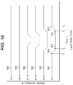
- FIG. 18 is a chart of impedance data indicating a liquid reflux event
- FIG. 19 is a chart of impedance data indicating a gas reflux event
- FIG. 20 is a chart of impedance data indicating a swallow event
- FIG. 21 is a chart of impedance data indicating a swallow and liquid reflux event
- FIGS. 22A-22E are schematics of an apparatus for measuring impedance and conductivity in accordance with exemplary embodiments
- FIG. 23 is a flowchart of an exemplary method and apparatus for measuring GRV
- FIG. 24 is a flowchart of an exemplary method and apparatus for determining the location a feeding tube via impedance measurements
- FIG. 25 is a flowchart of an exemplary method and apparatus for determining the location a feeding tube via local conductivity measurements
- FIG. 26 shows an embodiment of the GRV measuring device in a human stomach.
- FIG. 27 shows a stomach into which a substance containing a concentration of a GRV indicator is introduced.
- FIG. 28 shows a graph of the temperature of the stomach contents over time as sensed by sensor(s) after a bolus of cold substance is introduced into the stomach.
- FIG. 29 shows a graph of the concentration or pH of a GRV indicator over time after introduction into the stomach.
- FIG. 30 shows a graph of the temperature of the stomach contents over time as sensed by sensor(s) after multiple boluses of cold substance are introduced into the stomach.
- FIG. 31 shows an embodiment of the GRV measuring device where sensors are outside of the stomach.
- FIG. 32 shows an embodiment of the GRV measuring device where sensors are located along the length of the catheter or tube.
- FIGS. 33 and 34 show embodiments of the GRV measuring device where sensor(s) are at different location.
- FIG. 35 shows an embodiment of the GRV measuring device which is separate from a feeding tube.
- FIG. 36 shows a GRV measuring device where the GRV measuring device is inserted through a feeding tube.
- FIGS. 37 and 38 illustrate how the sensor(s) of the GRV measuring device may be located at various places relative to the feeding tube.
- FIG. 38 shows sensor(s) of the GRV measuring device in the pylorus
- FIGS. 39-41 show embodiments of the invention in which there is at least one transmitter and/or receiver to track location of the device within the stomach and/or stomach contents.
- FIGS. 42 and 43 show embodiments of the GRV measuring device for use percutaneously.
- FIG. 44 shows an embodiment of the GRV measuring device for use with a jejunostomy tube.
- FIGS. 45-49 show embodiments of the GRV measuring device.
- FIG. 50 shows an embodiment of the device where GRV and entry in the stomach is based on a continuously or intermittently monitored physical characteristic.
- FIG. 51 shows an embodiment of the device.
- FIG. 52 is a block diagram of a data processing system, which may be used with any embodiments of the invention.
- FIGS. 53 and 54 show other embodiments of the GRV measuring device.
- FIG. 55 shows the conductivity of various media when % gastric acid is increased.
- FIG. 56 shows pH and conductivity in various anatomical locations in a pig.
- FIGS. 57 and 58 show conductivity and oscillations of conductivity in various locations in the anatomy before and after feeding.
- FIGS. 59 and 60 show pH and oscillations of pH in various locations in the anatomy.
- FIG. 61 shows conductivity and pH before and after feeding.
- FIG. 62 shows an embodiment of the GRV measuring device with retention balloon.
- FIG. 63 shows a GRV measuring device with a pH sensor.
- FIG. 64 shows a GRV measuring device with a pH sensor.
- FIG. 65 shows a cross section of a feeding tube of the GRV measuring device.
- FIG. 66 shows an embodiment of the GRV measurement device.
- FIG. 67 shows an embodiment of the GRV measurement device.
- FIG. 68 shows an embodiment of the GRV measurement device.
- first, second, third etc. may be used herein to describe various elements, components, regions, layers and/or sections, these elements, components, regions, layers and/or sections should not be limited by these terms. Unless the context indicates otherwise, these terms are only used to distinguish one element, component, region, layer or section from another element, component, region, layer or section, for example as a naming convention. Thus, a first element, component, region, layer or section discussed below in one section of the specification can be termed a second element, component, region, layer or section in another section of the specification or in the claims without departing from the teachings of the present invention. In addition, in certain cases, even if a term is not described using “first,” “second,” etc., in the specification, it may still be referred to as “first” or “second” in a claim in order to distinguish different claimed elements from each other.
- spatially relative terms such as “beneath,” “below,” “lower,” “above,” “upper” and the like, may be used herein for ease of description to describe one element's or feature's relationship to another element(s) or feature(s) as illustrated in the figures. It will be understood that the spatially relative terms are intended to encompass different orientations of the device in use or operation in addition to the orientation depicted in the figures. For example, if the device in the figures is turned over, elements described as “below” or “beneath” other elements or features would then be oriented “above” the other elements or features. Thus, the term “below” as used in a relative sense may encompass both an orientation of above and below in the real world. The device may be otherwise oriented (e.g., rotated 90 degrees or at other orientations) and not affect the relationships described by the spatially relative descriptors.
- Determining the feeding tube location is important in a number of clinical settings. For all patients who receive a feeding tube, it is critical for the tube to be located in the stomach and not in the lungs. Feeding tubes inadvertently inserted into the trachea or lung airways occurs in 0.3% to 15% of all insertions according to Thomas et al, “Confirmation of nasogastric tube placement by colorimetric indicator detection of carbon dioxide: a preliminary report.” J Am Coll Nutr. 1998 April; 17(2):195-7, hereafter “Thomas” which is hereby incorporated in its entirety herein by reference. Inserting a feeding tube into the lungs can cause a number of severe complications, such as lung tissue perforation and pneumonia. Described embodiments are designed to ensure that the feeding tube is appropriately placed in the stomach and not in the trachea, bronchi or lungs.
- Proposed embodiments can be used with all types of feeding tubes, including the many different sizes (e.g., in a range of 6 Fr through 18 Fr) and feeding tube forms, which can include, but is not limited to, Levin feeding tubes, Salem Sump style feeding tubes, Dobhoff feeding tubes, Keofeed feeding tubes, small bore feeding tubes, pediatric feeding tubes, and nasojejunal feeding tubes.
- feeding tube forms which can include, but is not limited to, Levin feeding tubes, Salem Sump style feeding tubes, Dobhoff feeding tubes, Keofeed feeding tubes, small bore feeding tubes, pediatric feeding tubes, and nasojejunal feeding tubes.
- An exemplary embodiment for determining tube location is to use a sensor to measure acoustic signals to determine where the tube is positioned in the body.
- the acoustic sensor can measure different frequency ranges and types of vibrations including, but not limited to, vibrations associated with the frequency range of audible sounds (20-20,000 Hz).
- a piezoelectric sensor is used to measure the acoustic signals.
- a number of other exemplary sensors can be used to measure acoustic signals, including but not limited to an electret, condenser, piezoelectric crystal, piezoelectric ceramic, piezoelectric film, fiber optic microphone, or contact accelerometers.
- FIGS. 1A-1C shows an exemplary apparatus for a feeding tube with an acoustic sensor.
- the patient utilizes a feeding tube 102 to receive enteral nutrition into the stomach 103 .
- the enteral nutrition is administered by a feeding pump 116 , which is conveyed via a feeding pump tube 114 and a tube connector 112 .
- This feeding tube 102 contains an acoustic sensor 104 .
- this acoustic sensor 104 is located on the distal tip of the tube.
- the acoustic sensor 104 may be designed to detect certain vibrations, such as audible sounds, non-audible sounds or both audible and non-audible sounds.
- the acoustic sensor 104 is connected via a wire that is located in a second lumen that runs the length of the feeding tube 102 .
- the wire is embedded in the wall of the feeding tube 102 .
- the acoustic sensor 104 and the wire are connected into a single and separate component that is placed inside the main lumen of the feeding tube 102 . This separate component is then removed after the tube insertion is completed by pulling the proximal end of the component.
- a hydrophilic coating can be applied in the interior of the tube to reduce the friction in the interior and thus make it easier to remove the component.
- a code or other unique identifier can be integrated into the component and/or feeding tube 102 such that the unique identifier is received by the monitor 110 and validated to ensure the same component and/or feeding tube 102 are not used for multiple patients. Use on multiple patients may not be safe or hygienic.
- the code can be a series of printed alphanumeric characters or machine readable code (numeric and/or text represented by a bar code or in near field communication device) ascribed to the component and/or feeding tube that is entered into the monitor, or controller, 110 for a validation step.
- part of the component and/or feeding tube 102 can be disabled upon removal of the component and/or electrical connector 106 , making it infeasible to reuse the component and/or feeding tube in multiple patients.
- a wire can be connected to the electrical connector 106 , which is subsequently connected to the monitor 110 via the cable 108 .
- the sensor can connect to the monitor via a wireless interface, such as Wi-Fi, Bluetooth, cellular, or any other advantageous wireless network. It should be noted that use of the noun “monitor” herein refers to a computer, unless the context indicates otherwise.
- Such a computer can be configured to track a patient's condition, other data of a patient, medical instruments or equipment used to assist a patient, etc.
- the monitor can preferably but optionally include a display (e.g., monitor screen) or other indicator (e.g., audible alarm) for a clinician.
- a display e.g., monitor screen
- other indicator e.g., audible alarm
- This exemplary apparatus includes a sound emitter 118 .
- the sound emitter 118 is used to generate sounds that are then captured by the acoustic sensor 104 .
- the sound emitter 118 can utilize a piezoelectric transducer or other advantageous mechanisms to generate the desired sounds. “Sound” as used herein refers to any acoustic wave and is not limited to an audible sound. Thus, the emitted sounds of the sound emitter 118 may be audible or non-audible (or both).
- This sound emitter 118 is connected by the wire 124 to the electrical connector 106 .
- the sound emitter 118 can be designed such that a standard ECG pad can be placed on the end of the sound emitter.
- the sound emitter 118 can be built into an ECG pad, and thus can be connected to the wire 124 with the modified ECG clip.
- the sound emitter 118 may be placed close to the stomach.
- the sound emitter 118 may be placed on the abdomen just caudal to the left costal margin.
- this apparatus also includes two electrode sensors.
- the two electrode sensors are used to capture ECG data that can help the process of determining the location of the feeding tube.
- electrode sensors 120 - 122 are connected to electrical connector 106 by wires 126 - 128 .
- the electrode sensors are used to record heart patterns and interpret respiratory patterns. To determine heart patterns, the electrodes detect the electrical activity of the heart. When the electrical activity of the heart is displayed on an oscilloscope, a display of the monitor or paper chart, it is called an electrocardiogram (EKG or ECG).
- the respiratory pattern can be estimated from the ECG signal, hereafter called the ECG respiratory pattern, by detecting the respiratory sinus arrhythmia (RSA), that is the modulation of the R-R interval (i.e., the time between consecutive ECG R-waves) during the respiratory cycle, as described by de Geus et al, “Ambulatory measurement of respiratory sinus arrhythmia and respiration rate.” Biological Psychology, vol. 41, no. 3, pp. 205-227, 1995, hereafter “de Geus” which is hereby incorporated in its entirety herein by reference.
- RSA respiratory sinus arrhythmia
- the respiratory pattern can be determined through impedance pneumography, In this case, an impedance between two electrodes is measured. The impedance increases with inspiration and decreases with expiration.
- the electrode sensors 120 - 122 can be attached to the chest, arms, or other convenient or advantageous locations.
- the sound emitter 118 can also serve the function of an electrode sensor.
- the same standard ECG pad may have both the sound emitter and ECG conductive electrode mounted thereon. Elements of the sound emitter and ECG conductive electrode may be shared.
- the ECG conductive electrode may also function as a housing of the sound emitter. This can obviate the need for a second standalone electrode sensor in certain circumstances. For example, utilizing the sound emitter 118 as an electrode sensor can avoid the need for electrode sensor 122 .
- FIG. 2 An exemplary process for utilizing the apparatus described in FIGS. 1A-1C is provided in FIG. 2 .
- the clinician enters patient data into the monitor (also referred to herein as a controller) as shown in an exemplary depiction of a monitor screen shown in FIG. 3 .
- Patient data such as name 302 , ID number 304 , sex 306 , height 308 and weight 310 , can be entered into the monitor manually or through an electronic data interchange.
- the clinician can measure the distance between the nose, ear, and the umbilicus and enter the same into the monitor.
- the monitor based on this patient data, calculates and displays a target distance 312 for inserting the tube.
- This target distance indicates the length the tube should be inserted into the patient (e.g., a distance measured from the patient's front teeth, lips or nose) and can be visually verified by reference to measurement markings on the tube.
- the algorithm for calculating the target measurement can be based on nomogram data as described by Cirgin Ellett et al, “Predicting the Insertion Distance for Placing Gastric Tubes.” Clin Nurs Res 2005 February; 14(1):11-27, hereafter “Cirgin Ellett” which is hereby incorporated in its entirety herein by reference.
- the nomogram can be used to identify an appropriate target depth for tube insertion that is determined to correspond with correct placement of the end of the tube in the stomach of the patient.
- An insertion message 314 is presented instructing the clinician to pause the insertion once the tube has been inserted into the patient an intermediate distance (e.g., to a point where a specific distance marking on the tube is about to pass into the nose or mouth).
- this intermediate distance has been calculated as 25 cm.
- This intermediate distance can be determined by the computer as a function of the identified target depth for tube insertion (e.g., a ratio of the identified target depth or by referencing a look-up table pairing a range of tube insertion depths to corresponding intermediate distances).
- This distance marking signifies the point where the clinician should pause the insertion to monitor for one or more signals consistent with the tube being correctly inserted or consistent with the tube being incorrectly inserted.
- the signals can be generated by the patient, such as the sound of a heartbeat or the sound of breathing.
- the clinician can check the monitor to make sure that the tube is not in an inappropriate part of the airway, such as in the lower respiratory tract (i.e., past the glottis opening, or past the vocal folds, in the larynx, in the trachea or in the bronchi) and/or that auscultated heart pattern is consistent with correct position.
- Data that indicate that the tube is correctly positioned in the esophagus might include one or more of: 1) failure to detect the characteristic sounds of air moving in the lower respiratory tract, such as in the larynx, trachea and/or bronchi (“auscultated lower respiratory tract pattern”); 2) detection of the sounds made by the beating heart (“auscultated heart pattern”) within a range of appropriate intensities; 3) calculation of an appropriate distance between the acoustic sensor and sound emitter.
- step 203 the clinician attaches the two electrodes 118 , 120 to the body, with 118 being ideally placed on the abdomen just caudal to the left costal margin and 120 being placed in an accessible location such as the shoulder.
- the monitor will show a message 316 , if heart and respiration signals are being correctly received and processed.
- the clinician can proceed to step three and press a button 318 at the start of tube placement, thus initiating the capturing and analyzing acoustic signals by the monitor.
- the monitor continually analyzes these acoustic signals to detect three separate patterns, specifically the auscultated lower respiratory tract pattern that is associated with being located in the larynx, trachea and/or bronchi, the auscultated heart pattern, and the sound pattern from the sound emitter.
- step 204 the clinician begins to insert the feeding tube 102 into the patient.
- the feeding tube 102 As the feeding tube 102 is inserted, it is possible for the tube to enter the trachea 107 , as shown in FIG. 1 a .
- the acoustic sensor 104 As the tube is being inserted, the acoustic sensor 104 is capturing acoustic signals and sending this data back to the monitor 110 .
- the monitor 110 analyzes these acoustic signals to determine if the signals indicate an auscultated lower respiratory tract pattern that is typically recorded when the acoustic sensor is located in the larynx, trachea 107 or a bronchus 109 .
- the frequency of normal lung sounds auscultated from outside of the body are in the range of 50 to 2500 Hz according to Reichert et al, “Analysis of Respiratory Sounds: State of the Art.” Clin Med Circ Respirat Pulm Med. 2008 May 16; 2:45-58, hereafter “Reichert” which is hereby incorporated in its entirety herein by reference. Reichert also describes how tracheal sounds can reach up to 4000 Hz.
- the monitor also analyzes the ECG signals to determine an ECG respiratory pattern, which can be accomplished via the previously described exemplary approaches of detecting the RSA or changes in QRS amplitude.
- the monitor may perform an analysis to match the initially detected auscultated respiratory pattern with the ECG respiratory pattern that is derived from the electrodes, as shown in step 206 .
- this comparison can provide additional information that can help ensure that an auscultated respiratory pattern has been detected in the sound detected by the acoustic sensor.
- the monitor performs an analysis to match the key or identifiable points in the auscultated respiration pattern with the key or identifiable points in the ECG respiration pattern. These key or identifiable points can be derived from specific aspects of inhalation and exhalation related to respiration and the timing of such key or identifiable points.
- a key or identifiable point can be the timing of the peak of the auscultated lower respiratory tract pattern and the timing of the peak of the ECG respiration pattern.
- the timing of the trough of the auscultated respiration pattern and the timing of the trough of the ECG respiration pattern can be used as a key or identifiable point.
- one respiration pattern can be used as a starting point to determine if the other respiration pattern is a match.
- the ECG respiration pattern by continually measuring the ECG respiration pattern, it is possible to generate a baseline of key or identifiable points of the respiration pattern and then analyze the auscultated respiration pattern to determine the corresponding existence of these key or identifiable points, or to analyze just these key or identifiable points to determine if there is a match or correlation of sufficient magnitude.
- This pattern matching can include one or more of data smoothing, time series analysis, cross-correlation analysis, convolution analysis, regression analysis, and neural networks. Matching the two patterns can be advantageous, since the auscultated respiration pattern is more likely to be a valid respiration pattern indicative of being located in the larynx, trachea or bronchi when the auscultated respiration pattern matches the continually measured ECG respiration pattern derived from the ECG signal.
- the two patterns i.e., the ECG respiratory pattern and the auscultated respiratory pattern
- the acoustic sensor is located in the lower respiratory tract, such as the larynx, trachea or a bronchus.
- the results of this respiratory pattern analysis are presented on the monitor as shown in step 207 . If the results are negative, the monitor displays the message that the feeding tube is not located in the trachea or a bronchus. If an auscultated lower respiratory tract pattern is detected (e.g., a match or significant correlation with the ECG respiratory pattern is detected), the monitor can indicate a visual alarm, and/or an auditory alarm, to warn the clinician that the tube may be located within the lower respiratory tract, such as the larynx, trachea or a bronchus. The clinician can then stop tube insertion and withdraw the tube.
- an auscultated lower respiratory tract pattern e.g., a match or significant correlation with the ECG respiratory pattern is detected
- the monitor can indicate a visual alarm, and/or an auditory alarm, to warn the clinician that the tube may be located within the lower respiratory tract, such as the larynx, trachea or a bronchus. The clinician can then stop tube insertion and withdraw the tube.
- the acoustic sensor detects the auscultated heart pattern as the feeding tube is being inserted.
- the auscultated heart pattern can be detected immediately upon tube insertion in the body since the heart can emit a strong signal, i.e., a signal that is loud and can travel significant distances within the body.
- the spectrum for capturing the auscultated heart pattern is generally defined as between 20 and 100 Hz according to Reichart.
- There are a number of advantageous means to analyze heart sounds to determine the auscultated heart pattern including but not limited to Fourier transform and wavelet transform according to Debbal et al, “Computerized heart sounds analysis.” Comput Biol Med. 2008 February; 38(2):263-80. Epub 207 November 26, hereafter “Debbal” which is hereby incorporated in its entirety herein by reference.
- the monitor detects an auscultated heart pattern
- the monitor will then perform an analysis to match the auscultated heart pattern with the ECG heart pattern that is derived from the electrodes, as shown in step 209 .
- this comparison can provide additional information that can help ensure that an auscultated heart pattern has been detected.
- a number of processing steps can be required to perform this pattern matching, including but not limited to data smoothing, time series analysis, cross-correlation analysis, convolution analysis, regression analysis, and neural networks. Matching the two patterns is advantageous, since the detected heart sound pattern is more likely to be an actual heart sound pattern when the pattern matches the continually measured and well-known ECG-based heart pattern derived from the electrodes. Matching these two patterns therefore increases the confidence that the acoustic sensor is correctly detecting the heart pattern.
- the acoustic sensor 104 moves within close proximity of the heart 111 .
- the monitor 110 is continually measuring the intensity of the heart sound as the feeding tube 102 transits the length of the esophagus 101 as it moves toward the stomach 103 .
- the heart sound should increase in intensity, or amplitude.
- the heart sound should decrease in intensity, or amplitude.
- This increasing and decreasing intensity in the measured auscultated heart pattern can be analyzed to determine an approximate location of the feeding tube, e.g., a location of the feeding tube's relative to the heart of the patient.
- the measurement of the auscultated heart pattern will be analyzed over time to determine if it matches a similar increasing and decreasing pattern of intensity, as shown in step 210 .
- a number of processing steps can be required to perform this pattern matching, including but not limited to data smoothing, time series analysis, cross-correlation analysis, convolution analysis, regression analysis, and neural networks.
- the maximum amplitude of the auscultated heart pattern can be identified and plotted versus time.
- step 211 the results of this analysis are shown on the monitor, such as a message describing the status of the analysis and a chart showing the intensity of the auscultated heart pattern over time.
- the monitor analyzes the acoustic signals coming from the sound emitter 118 and captured by the acoustic sensor 104 , and calculates the distance between the sound emitter and acoustic sensor.
- the acoustic signal can take many exemplary forms, including but not limited to a sound pulse, a continuous variable tone and can be emitted at different audible, ultrasound, or other advantageous frequencies.
- the monitor can perform calculations to determine the distance between the sound emitter and the acoustic sensor.
- v the speed of sound through the patient
- the monitor displays the status of the distance calculation and a chart showing these distance calculations over time.
- the monitor may display a distance that is derived from the distance between the acoustic sensor 104 and the sound emitter 118 (e.g., a distance remaining to complete insertion of the feeding tube).
- the clinician pauses the insertion to check the monitor after inserting the tube approximately halfway into the patient, such as in FIG. 1 b .
- the purpose of checking the monitor is to determine if any of the summary data would indicate the tube is located in the trachea or bronchi, or if the tube appears to be located correctly in the esophagus, as shown step 214 .
- the clinician pauses the insertion based on tube markings close to the point of entry, such as the nose or mouth, indicating the tube had been inserted 25 cm.
- exemplary markings and insertion distances may apply, such as those having a dependence on or calculated based upon the identified target depth or otherwise calculated as a function of the data of the patient (such as size, age, sex, etc.).
- the clinician can check the monitor to see if there is any indication the tube tip is located in the larynx, trachea or bronchi.
- the clinician can also check the monitor to see if the auscultated heart pattern has increased in intensity, which would be an indication that tube has progressed down the esophagus and is near the heart.
- the combination of no indicated auscultated lower respiratory tract pattern along with an increase in intensity of an auscultated heart pattern indicates that the tube is progressing correctly down the esophagus towards the stomach.
- the clinician can also check the monitor to see if the calculated distance between the acoustic sensor and the sound emitter has decreased during the period of insertion. This decreasing distance indicates that tube has progressed down the esophagus, and conversely has not become coiled in the mouth, nasopharynx or hypopharynx.
- the combination of no auscultated lower respiratory tract pattern, an increase in intensity of an auscultated heart pattern, and decreasing distance between the acoustic sensor and the sound emitter provide a strong indication that the tube is progressing correctly down the esophagus towards the stomach.
- any combination of an indication of an auscultated lower respiratory tract pattern, an indication that the auscultated heart pattern intensity has not increased with insertion of the tube, and no evidence of decreasing distance between the acoustic sensor and the sound emitter, may indicate the tube is not progressing correctly down the esophagus towards the stomach and may be in the trachea or bronchi or has become coiled.
- the clinician can then decide whether to proceed with the tube insertion or take other action, such as removing and reinserting the feeding tube or taking an X-ray to confirm the placement of the tube.
- the acoustic sensor 104 is shown in the stomach 103 and located more closely to the sound emitter 118 .
- the clinician can check the monitor to see the distance between the sound emitter 118 and the acoustic sensor 104 . The clinician can then compare this calculated distance with a visual identification of seeing where the sound emitter 118 is physically placed on the patient and making an assessment as to whether the distance corresponds with the feeding tube 102 being correctly placed in the stomach 103 and conversely not in the trachea or bronchi 109 .
- the calculated distance between the sound emitter 118 and acoustics sensor 104 should decrease.
- step 215 the clinician reviews the summary information and inputs the distance marking on the tube into the monitor. This distance marking corresponds with the furthest point the tube has been inserted into the patient.
- the monitor compares the inputted tube distance with the recommend insertion distance calculated in step 202 . If the difference between the two insertion distances is above a defined threshold, the monitor will display a message that the tube insertion distance may not be sufficient for proper location in the stomach. If the difference between the two insertion distances is below a defined threshold, the monitor will display a message that the tube insertion distance is sufficient.
- the threshold for the difference in tube distance is 5 cm; in another embodiment, the threshold for the difference is 10% of the identified target depth.
- FIG. 4 depicts an example monitor screen where all assessments have indicated that the tube is placed correctly in the stomach.
- the most visible indication on the screen is the status indicator 401 , which displays the color green to signify the tube is placed correctly. If the monitor algorithm calculations result in an indication that the tube is not placed correctly, or if there is not enough information to determine if the tube is placed correctly, the status indicator 401 displays the color yellow. If the monitor algorithm calculations result in an indication that the tube is placed in the trachea or a bronchus, the status indicator 401 displays the color red.
- a text status indicator 402 conveys the status of the tube placement. In the scenario for FIG. 4 , the text status indicator indicates the “Tube Placed Correctly”.
- the heart and respiratory signal indicator 403 displays a message, “Heart and Respiratory Connected”, signaling that the heart and respiratory signals from the electrodes are being correctly captured.
- the trachea and lung sounds signal indicator 404 displays a message, “No Trachea/Lung Sounds Detected”, signaling that the acoustic sensor and monitor are currently not detecting any trachea or lung sounds, and thus indicating the feeding tube tip is not in the trachea or bronchus.
- the heart transit indicator 405 displays a message, “Tip Passed Heart in Esophagus”, signaling that the acoustic sensor and monitor detected the pattern of the tube tip passing by the heart during transit down the esophagus.
- the indication of the tube tip passing by the heart during transit down the esophagus is further confirmation that the tube tip is not located in the trachea or bronchus.
- the sound emitter distance indicator 406 displays a message, “Tip 3 Cm from Sound Emitter”, signaling the acoustic sensor is located 3 cm from the sound emitter.
- the indication that the acoustic sensor is located a short distance from the sound emitter, which should be located caudal to the left costal margin, is further confirmation that the tube tip is located in the stomach, and conversely is not located in the trachea or bronchus.
- the tube insertion indicator 407 displays a message, “Tube Insertion of 45 cm Is Sufficient”, signaling that the inputted tube insertion distance is sufficient for the tube to be placed correctly in the stomach. If the clinician is satisfied that the data presented on the monitor is sufficient to confirm the tube is correctly placed in the stomach, the clinician can then submit the electronic medical record by pressing button 409 .
- the clinician also has the option to review more detailed data on the monitor. By pressing the Data Chart View button 408 , the clinician can view more detailed information in chart form.
- FIG. 5 shows this optional view to review the data in chart form.
- the clinician can review the Heart Sound Intensity chart 501 to see a time-based view of the heart sound intensity data. If the feeding tube transited the esophagus correctly, this would be indicated by an increase in auscultated heart pattern intensity as the tube tip gets closer to the heart and a decrease in intensity as it passes the heart on the way towards the stomach.
- the clinician can also view feeding tube tip distance 502 over time (e.g., graphically), which should generally indicate a decrease in tube tip distance from the sound emitter as the tube is being inserted.
- the clinician may review the heart sound intensity with respect to the measured feeding tube tip distance.
- the measured feeding tube tip distance may be plotted along the x-axis and the heart sound intensity may be plotted along the y-axis.
- the clinician may repetitively sample the heart sound intensity at the same distances by inserting and retracting the feeding tube.
- the clinician can still refer to the monitor to see an update of the distance between the acoustic sensor and the sound emitter. This may be valuable to determine if the tube has moved during treatment and if the tube insertion may need to be adjusted.
- the clinician can utilize the same monitor for multiple patients.
- the monitor associates a unique ID with each feeding tube. If the feeding tube was disconnected from the monitor and subsequently reconnected, the monitor can utilize the unique ID of the feeding tube to associate all previously entered and measured data from that feeding. Therefore, a clinician can utilize one monitor to insert feeding tubes into multiple patients, and as necessary reconnect the monitor to a tube to assess the location of the tube without having to reenter any patient data. A history of patient data is stored such that any previously entered patient data can also be accessed and associated with any new feeding tubes.
- FIG. 6 shows an alternative embodiment of the apparatus to determine feeding tube location.
- two sound emitters 601 and 602 are used to determine the distance from the acoustic sensor 104 to the sound emitters.
- the sound emitters 601 and 602 are connected to a rigid member 603 .
- the rigid member 603 is connected via wire 604 to electrical connector 106 .
- the two sound emitters 601 and 602 also serve as electrodes to capture heart and respiratory signals.
- the distance between the acoustic sensor 104 and the sound emitters 601 and 602 that can be calculated in the same fashion as described elsewhere herein.
- the distance between acoustic sensor 104 and sound emitter 601 is known and the distance between acoustic sensor 104 and sound emitter 602 is known. Additionally, the distance between sound emitter 601 and sound emitter 602 is known given their fixed location on the rigid member 603 . These three distances form a triangle, so knowing the lengths of each side of the triangle makes it possible to calculate the angles of this triangle and thus determine the location of the acoustic sensor.
- the location of the acoustic sensor With one sound emitter (e.g., just one of 601 and 602 ), you can determine the location of the acoustic sensor as being a certain distance away from the one acoustic sensor (e.g., determined to be on a point of the surface of an imaginary three-dimensional sphere having the location of the one acoustic sensor as its center). In this exemplary embodiment with two sound emitters, you can determine the location of the acoustic sensor as being on a point of the circumference of an imaginary two-dimensional circle 605 . This level of accuracy in determining the location of the acoustic sensor 104 may be advantageous.
- the imaginary circle on which the acoustic sensor 104 is determined to lie will be horizontal.
- a vertical location of the acoustic sensor 104 can be accurately determined even if its horizontal location has been determined via this calculation to be on the horizontal imaginary circle.
- Triangulation can be used to calculate a point in space relative to the location of the three sound emitters.
- a sphere with the corresponding sound emitter as its center can be determined, with the radius of the sphere representing the determined distance between the sound emitter and the acoustic sensor and the surface of the sphere representing a possible location of the acoustic sensor.
- the intersection of these three determined spheres can be determined as the location of the acoustic sensor.
- Another approach is to use each pair of the three sound emitters to calculate possible locations along a corresponding imaginary circle. The intersection of these three imaginary circles will correspond to a determined location of the acoustic sensor 104 .
- FIG. 7 shows an alternative embodiment of the apparatus to determine feeding tube location.
- the apparatus utilizes a mobile device 701 (shown as 701 a , 701 b and 701 c at respective different locations).
- This mobile device 701 can take the form of a mobile phone, tablet, or other advantageous mobile device.
- the mobile device 701 uses a wireless connection to communicate with the monitor 110 .
- a tip component 707 is located in the tip of the feeding tube and, in this embodiment, is used to sense the acoustic signals from the mobile device 701 .
- the mobile device 701 continuously emits a acoustic signal.
- the tip component 707 is the acoustic sensor 104 . The signal received by the tip component 707 is used by the monitor 110 to calculate the distance between the tip component 707 and the mobile device 701 .
- An exemplary process is to move the mobile device 701 while the tip component 707 receives the sound signals.
- mobile device 701 a is a calculated first distance from tip component 707 where the distance can be visualized as the radius of a first sphere 702 (with mobile device 701 a at the center) and the location of the tip component 707 is somewhere on the surface of that first sphere 702 .
- mobile device 701 b is a calculated second distance from tip component 707 where the distance can be visualized as the radius of a second sphere 703 (with mobile device 701 b at the center) and the location of the tip component 707 is somewhere on the surface of that second sphere 703 .
- mobile device 701 c is a calculated third distance from tip component 707 where the distance can be visualized as the radius of a third sphere 704 (with mobile device 701 c at the center) and the location of the tip component 707 is somewhere on the surface of that third sphere 704 . If you assume the acoustic sensor is not moving between the three positions then the intersection point 705 where each of the three spheres intersects is the location of the tip component 707 in three-dimensional space. Determining location via this process is called trilateration, as described by Wikipedia, “Trilateration”. Wikipedia. Web. 3 Mar. 2015. Web. ⁇ http://en.wikipedia.org/wiki/Trilateration>. To determine this intersection point 705 , you need to first determine the location of the mobile device 701 in each position relative to the other positions.
- the location of each position relative to the other positions can be determined by utilizing an accelerometer and gyroscope contained in the mobile device 701 .
- the accelerometer and gyroscope can enable calculating the position, orientation and velocity of the mobile device and thus enable determining a relative location at each time interval.
- the mobile device emits sound signals at 20 Hz, or 20 times per second, and therefore continually calculates relative location 20 times per second. Other exemplary frequencies for emitting a sound signal and calculating relative location can be used.
- the accuracy of determining the relative location of the mobile device 701 can be enhanced by using an additional reference point.
- a known visual reference 706 can be utilized.
- a camera contained in the mobile device 701 can be utilized to view the visual reference 706 .
- An exemplary form for this visual reference 706 can be a two dimensional rectangle with a length of 2 cm on one side and 4 cm on the other side attached to the body of the patient.
- Another exemplary form for this visual reference 706 can be a high contrast, two dimensional marker of known dimensions which lacks reflection symmetry and/or rotation symmetry attached to the body of the patient. Other forms and dimensions can be used.
- algorithms in the sound emitter 701 can analyze data from the camera to calculate the distance from the visual reference 706 to the mobile device 701 based on the characteristics of the visual reference 706 , such as calculated diameter of the disk compared to the known diameter and the shape of the disk compared to the known shape.
- the relative position of tip component 707 can be communicated to the clinician via an augmented reality interface on a screen contained in the mobile device 701 .
- Augmented reality is defined as viewing data in what appears to be a camera field of view.
- the clinician can look at the screen of the mobile device 701 and see what appears to be a real-time video feed of the patient. The clinician can first wave the mobile device 701 forward, then backward, and from side to side over the patient to calculate a relative location of the tip component 707 . The clinician can then see on the screen of the mobile device 701 a representation of the tip component 707 on the screen relative to its position within the patient's body.
- the visual representation of the patient's body on the screen can exhibit a transparency effect to create the illusion that you can see the tip component 707 within the patient's body.
- An exemplary embodiment of this transparency effect can be within the sight line of the tip component 707 , the patient's body has an algorithm generated surface appearance that makes it look as if you're looking beneath the surface of the patient's body.
- the clinician should therefore be able to see the location of the tip component 707 relative to the patient's anatomy and determine if the tip component 707 is correctly placed in the stomach, and conversely is not placed in the trachea or bronchus.
- an algorithm-generated appearance can also simulate a visual representation of organs such as the stomach, lungs and heart to assist the clinician and determining the location of the acoustic sensor.
- an alternative (or additional) apparatus can be used in a similar process previously described for the mobile device 701 and the tip component 707 .
- This alternative (or additional) apparatus comprises a magnetic field sensor, or magnetometer, contained within the mobile device 701 .
- the magnetometer can measure the strength of the magnetic field that is around the mobile device 701 .
- the tip component 707 can contain magnetic material with a known magnetic moment.
- the tip component 707 consists of coiled wiring that upon application of a known electric signal creates a known magnetic moment.
- the clinician can also wave the mobile device 701 forward, then backward, and from side to side over the patient.
- the distance is instead calculated based on the strength of the magnetic field measured from the magnetic material in the tip component 707 .
- the measurement of distance (measured in meters) from the mobile device 701 in the tip component 707 can be calculated using the following exemplary formula:
- ⁇ 0 represents the permeability constant (4 ⁇ 10-7 T m/A)
- ⁇ is the magnetic moment of the magnetic material in the tip component 707
- B is the magnetic field (measured in tesla).
- the clinician can similarly be able to view an augmented reality visual representation of the tip component 707 relative to the patient's body on the screen of the mobile device 701 .
- the accuracy of determining the relative location of the mobile device 701 can also be enhanced by using a known visual reference 706 , as previously described.
- FIG. 8 shows an example of this peristaltic movement.
- a peristaltic wave 801 is shown moving through the stomach 103 .
- peristaltic waves 801 move the food through the stomach 103 and out through the pyloric sphincter 803 into the duodenum 804 according to Ehrlein et al, “Gastrointestinal Motility.” Class tutorial, Technische Universitat Munchen, 2014, hereafter “Ehrlein” which is hereby incorporated in its entirety herein by reference.
- Ehrlein During the movement of a peristaltic wave 801 , muscles in the stomach 103 contract to push food 802 from the proximal stomach 103 towards the pylorus 803 at the distal end of the stomach.
- the stomach 103 moves food 802 towards the pylorus 803 by generally contracting and thus shrinking the size of the overall stomach 103 ; this phenomenon is called tonic contraction.
- the peristaltic waves 801 and tonic contraction encourage the food 802 to be further broken down and thus digested.
- Food that is broken down to a point where it is more of a liquid is referred to as gastric chyme 805 .
- the peristaltic waves 801 more easily move this gastric chyme 805 past the pylorus 803 and into the duodenum 804 , and conversely larger undigested pieces of food 802 are pushed back into the stomach 103 to be further digested in an effect called retropulsion.
- an acoustic sensor is used to measure gastric motility.
- This acoustic sensor 104 can be located on the distal tip of the feeding tube 102 , as shown in FIG. 8 .
- This acoustic sensor 104 can measure different frequency ranges and types of vibrations including, but not limited to, vibrations associated with frequency range of audible sounds (20-20,000 Hz).
- a piezoelectric sensor is used to measure the acoustic signals.
- a number of other exemplary sensors can be used to measure acoustic signals, including but not limited to an electret, condenser, piezoelectric crystal, piezoelectric ceramic, piezoelectric film, or contact accelerometers.
- the vibrations measured by the acoustic sensor 104 can originate from a number of sources, including but not limited to peristalsis, gas bubbles, flatulence, and sounds from nearby organs, such as the lungs, heart, or small bowel.
- sources including but not limited to peristalsis, gas bubbles, flatulence, and sounds from nearby organs, such as the lungs, heart, or small bowel.
- the study of phonoenterography revealed that bowel sounds increased in intensity during a meal and high intensity persisted for more than two hours after the meal according to Watson et al, “Phonoenterography: the recording and analysis of bowel sounds.” Gut. 1967 February; 8(1): 88-94, hereafter “Watson” which is hereby incorporated in its entirety herein by reference.
- Bowel sounds are complex with a mixture of tones and often in a sequence of closely connected sounds in a frequency range of 150 to 5,000 Hz.
- an acoustic sensor detects the vibrations associated with the movement of a peristaltic wave.
- the acoustic sensor 104 can be a piezoelectric-based accelerometer.
- the accelerometer is capable of measuring movement (e.g., physical movement of the accelerometer itself), such as the peristaltic wave 801 that moves down the stomach 103 .
- the peristaltic wave 801 can be detected by detecting a pattern having a frequency of one to three contractions per minute, as shown in FIG. 8 .
- a positive indication of gastric motility (e.g., between 1 and 3 contractions/waves per minute) should correlate with the patient tolerating enteral nutrition, and therefore have sufficient sensitivity.
- a negative indication of motility e.g., less than 1 contractions/waves per minute
- motility can help identify patients that are not tolerating nutrition, enabling the clinician to adjust care and monitor the patient more closely.
- the monitor can routinely monitor other body sounds as a means to check if the apparatus is functioning correctly.
- the monitor routinely captures an auscultated heart pattern. If the auscultated heart pattern is routinely captured correctly, this indicates the acoustic sensor is functioning correctly, and thus it can be inferred it is also correctly capturing gastric motility vibration measurements.
- the monitor can routinely capture acoustic signals from the sound emitter 118 to confirm the acoustic sensor 104 is functioning correctly.
- an acoustic sensor measures the vibrations associated with oscillating gas bubbles in the small intestine.
- the acoustic sensor 104 can be a piezoelectric-based accelerometer.
- Bubbles can be identified by their oscillating frequencies. Further, the size of the bubbles can also be determined by the measured frequency.
- the size of the bubbles can change as they move within the different sized structures of the small intestine.
- the pattern and frequency of the bubbles is analyzed to assess gastrointestinal motility and other gastric functions.
- the analysis of gas bubbles in the small intestine can be combined with the analysis of peristaltic waves in the gastric environment, or other sensor data, to assess overall gastrointestinal motility.
- the various gastric motility measurements can additionally be used to determine the effectiveness of the type and amount of enteral nutrition.
- the patient condition can also be a factor in determining the effectiveness of the type and amount of enteral nutrition.
- GMV Gastric Residual Volume
- Gastric residual volume is typically measured by attaching a large syringe to the proximal opening in the feeding tube and suctioning all of the gastric contents into the syringe. The syringe has measurement markings denoting the volume in milliliters, which is then recorded in the patient's medical record.
- a low volume of gastric contents may indicate the patient is tolerating enteral nutrition and has sufficient gastric motility.
- a high-volume of gastric contents may indicate the patient is not tolerating enteral nutrition and does not have sufficient gastric motility.
- a high-volume of gastric contents is defined as 250 mL according to McClave et al, “Guidelines for the provision and assessment of nutrition support therapy in the adult critically ill patient.” JPEN J Parenter Enteral Nutr. 2009 May-June; 33(3):277-316, hereafter “McClave” which is hereby incorporated in its entirety herein by reference.
- a clinician can adjust the care of the patient based on receiving a high gastric residual volume measurement, such as reducing the rate of tube feeding, prescribing pro-kinetic agents or raising the head of bed.
- a high gastric residual volume may not always correspond to a gastric motility problem.
- a gastric residual volume of over 250 mL may be required to trigger gastric emptying by the stomach into the small intestine, and thus a gastric residual volume of over 250 mL may be part of normal digestion.
- these gastric residual measurement calculations are often performed every four hours in acute care patients receiving enteral nutrition. This procedure therefore takes time away from the clinicians that otherwise can be used in treating patients. The procedure is also often unsanitary due to the removal and reinsertion of gastric contents.
- an indicator dilution technique is used to measure GRV.
- Indicator dilution techniques are well known and are widely used in medicine, scientific work and industry for measuring fluid (gas or liquid) volumes or flow rates. As described by Schoeller “Indicator Dilution Methods.” Quality of the Body Cell Mass. Serono Symposia USA 2000, pp 55-67, hereafter “Schoeller” which is hereby incorporated in its entirety herein by reference, indicator dilution methods for measuring volume (or flow rate) are based on the principle of conservation of mass.
- volume (pool size) dose of tracer/concentration of tracer.
- the validity of indicator dilution approach depends on four assumptions. First, the indicator mixes rapidly and thoroughly with the fluid in the pool. Second, after mixing is complete, the concentration of the indicator is homogeneous in the pool volume. Third, the indicator is distributed only to the pool volume of interest. Fourth, the tracer is stable (over the time period required for the measurements).
- Indicators often are chemicals that can be easily detected, using appropriate analytical means. Examples include: radio-labelled compounds (e.g., tritium-labelled water), stable isotope-labelled compounds (e.g., 13C-labelled glucose), dyes (e.g., indocyanine green dye), or easily detected chemical entities (e.g., Li+cation, polyethylene gycol).
- radio-labelled compounds e.g., tritium-labelled water
- stable isotope-labelled compounds e.g., 13C-labelled glucose
- dyes e.g., indocyanine green dye
- easily detected chemical entities e.g., Li+cation, polyethylene gycol.
- GRV has been measured, using an indicator dilution approach.
- a model stomach showed that dilution of phenol red dye can be employed to determine “gastric” volume according to Hurwitz, “Measuring gastric volume by dye dilution.” Gut 1981 February; 22(2):85-93, hereafter “Hurwitz” which is hereby incorporated in its entirety herein by reference.
- GRV measurement in patients was demonstrated using polyethylene glycol (PEG) as the tracer and turbidometry as the means for measuring PEG concentrations according to Hardy et al, “Determining gastric contents during general anaesthesia: evaluation of two methods.” Can J Anaesth.
- PEG polyethylene glycol
- Temperature also can be a useful tracer.
- cardiac output i.e., the flow rate of blood through the heart
- gastric residual volume is determined by measuring the temperature of gastric contents before and after a control.
- a temperature sensor is located on the distal tip of the feeding tube, which can be connected via a wire to the monitor.
- the monitor 110 can take continuous temperature measurements of the gastric contents.
- the apparatus is similar to that shown in FIG.
- a temperature sensor or thermistor is used instead of an acoustic sensor 104 located the distal tip.
- the monitor can then control a known amount of fluid to be introduced through the feeding tube and into the stomach, which in an exemplary embodiment can be 50 mL of distilled water cooled to a temperature of 1° C. Utilizing water as a control can be advantageous, since acute care patients require hydration and water is a safe substance.
- the temperature sensor can then continually measure the change in temperature of the gastric contents after introducing this control of cooled water.
- V injectate is the volume of cold water injected into the stomach via the feeding tube.
- T before is the temperature of the gastric contents prior to injecting the aliquot of cold water.
- T injectate is the temperature of the cold injectate.
- T after is the temperature of the gastric contents after the injection of the indicator.
- k 1 is a dimensionless constant that depends on the specific heat content of water, the density of water, the specific heat content of gastric contents and the density of gastric contents.
- k 2 is a dimensionless constant that accounts for the dead space volume of the feeding tube and perhaps other unmeasured sources of systematic error.
- the rate in which the temperature change occurs throughout the gastric contents can be used to calculate GRV.
- Calculating the rate of change of the temperature can add information to improve the calculation of GRV or provide other insights that may prove helpful to the clinician.
- the nature of the stomach environment and the gastric contents are such that significant mixing occurs as part of digestion and the subsequent measured temperature change will be reflective of the entirety of the gastric contents.
- Other factors that can be used to calculate GRV include the rate of enteral nutrition, the rate of gastric emptying, and medicines that may be introduced into the gastric environment. Since there may be unaccounted—for factors that may influence the accuracy of the gastric residual volume calculation, the algorithm can also present a probability measurement associated with the volume calculation to help the clinician understand the relative certainty in the GRV calculation.
- Gastric Residual Volume can be determined in certain circumstances by measuring changes in the impedance of an alternating current applied in the abdominal region by electrodes according to Soulsby et al, “Measurements of gastric emptying during continuous nasogastric infusion of liquid feed: electric impedance tomography versus gamma scintigraphy.” Clin Nutr. 2006 August; 25(4):671-80, hereafter “Soulsby” which is hereby incorporated in its entirety herein by reference.
- 16 electrodes ECG pads
- Impedance changes are measured by passing a sinusoidal alternating current (50-100 kHz; 1 to 10 mA) between one pair of electrodes on the abdomen and measuring the resulting voltage drop between another pair of electrodes.
- a sinusoidal alternating current 50-100 kHz; 1 to 10 mA
- impedance is measured from all the possible combinations of pairs of electrodes, and an impedance versus time curve is generated by a proprietary algorithm.
- the system is “calibrated” by introducing a 100 mL bolus of tube feeding into the stomach.
- the conductivity of the calibrating bolus of tube feeding formula is increased by dissolving 17 g/100 mL of table salt (NaCl) in the formula prior to introducing it into the stomach.
- McClelland and Sutton The approach described by McClelland and Sutton is similar to the one described above, except that only four electrodes are employed (two on the anterior epigastrium and two on corresponding locations on the back).
- the system described by McClelland and Sutton uses “standard” impedance cardiography equipment for signal generation and detection, but employs appropriate low-pass filtering to exclude interference from cardiac signals.
- gastric volume is not measured; rather, the impedance based system is designed only to measure fractional changes in gastric volume after a test meal as a function of time.
- the primary read-out is the half-time (t 1/2 ) for gastric emptying.
- a GRV monitoring device can employ the electrode placement strategy described by McClelland and Sutton, as shown in FIG. 9 .
- a plurality of electrodes are placed on the abdomen.
- four electrodes 118 , 120 , 902 and 904 are placed on the abdomen.
- An alternating electric current is driven through the patient's body between electrodes 118 and 902 .
- the voltage between electrodes 120 and 904 may also be measured.
- the voltage measurement is filtered to only reflect the changes within the frequency range of the alternating current between electrodes 118 and 902 .
- the voltage measurement comprises an impedance measurement whose amplitude depends in part on the GRV. Electrodes can have plural functions.
- electrode 118 can record ECG signals during tube placement and serve as an anterior electrode that inputs alternating current for subsequent impedance measurement.
- Electrode 118 can be placed in the angle between the left costal margin (of the rib cage) and xyphoid process of the sternum (breast bone).
- the electrode 120 can record ECG signals and also serve as an anterior electrode for measuring voltage for impedance measurement.
- Electrode 120 can be placed just caudal to the left costal margin at location that is about 4 finger-breadths (about 4-5 cm) to left of the midline.
- electrode 902 can be placed on the posterior of the patient and input alternating current for subsequent impedance measurement.
- Electrode 904 can also be placed on the posterior of the patient and measures voltage along with electrode 120 for impedance measurement.
- the same electrode placement strategy can be employed, except instead of placing a pair of electrodes on the posterior, these electrodes instead can be located on the distal end of the feeding tube and connected by wires (or conductive ink) to an appropriate fitting on the proximal end of the tube.
- electrode 120 on the anterior abdominal wall and electrode 910 on the feeding tube can input, or “inject”, an alternating current (50-100 kHz; 1 to 10 mA) into the patient.
- Each of the second electrode 912 on the distal end of the feeding tube and electrode 118 on the anterior abdominal wall can receive an alternating current from each of electrodes 120 and 910 .
- the impedance of the gastric contents plus other relevant tissues e.g., fat, muscle, and skin
- the patient is electrically isolated from the external environment during this procedure.
- FIG. 10 An exemplary process for utilizing the apparatus described in FIG. 10 to measure GRV via impedance is provided in FIG. 10 .
- the clinician installs electrodes on the abdomen and inserts the feeding tube.
- the nutrition type and infusion rate is entered into the monitor 110 .
- the clinician confirms that the patient is prescribed acid suppression medication via the monitor 110 .
- a known quantity e.g., 50 mL
- three-point calibration can be achieved by injecting a second bolus of tube feeding formula (e.g., another 50 mL aliquot) and again recording impedance.
- impedance measurement is initiated via the monitor 110 .
- nutrition is initiated via the feeding pump 116 .
- GRV measurement is then displayed on the monitor 110 per step 1007 .
- step 1008 in audible and/or visual alarm is initiated if the GRV exceeds a defined threshold.
- This defined threshold of GRV measurement can be customized via a setup configuration of the monitor 110 , and may include a default configuration based on patient sex, height, weight, feed type, fluid restriction, propofol rate, etc.
- the monitor 110 can display whether peristalsis has been detected or not. Knowing if peristalsis has been detected can help the clinician determine if nutrition is being tolerated. Peristalsis can be detected through described embodiments or other advantageous means.
- step 1010 a probability is calculated to determine if the GRV measurement is being captured and analyzed correctly.
- This probability will be based on a number of factors, including but not limited to the GRV measurement value, the trending of GRV measurement values, nutrition type and infusion rate, prescription of acid suppression medication, calibration results, and peristalsis detection.
- the results of this probability calculation can be displayed on monitor 110 .
- the clinician may decide to perform an optional additional calibration. In this optional calibration, the impedance measurement is noted via the monitor 110 .
- the stomach is then emptied completely by aspiration of contents via the feeding tube.
- the clinician then manually measures the volume of the aspirated gastric contents.
- the clinician enters the manually measured volume of the gastric contents into the monitor 110 .
- the monitor 110 then utilizes the manually measured volume to calibrate the GRV measurements going forward.
- the GRV measurement results are entered into the EMR system.
- a conductivity sensor can be located at the distal end of the feeding tube.
- the conductivity sensor can take the form of electrode 910 .
- the conductivity sensor can be utilized to determine the conductivity (inverse of resistivity) of the gastric contents. This conductance measurement can be helpful for estimation of GRV, since the estimation of GRV using measurements of epigastric impedance (see FIG. 10 ) depends on conductivity of the gastric contents and the other structures (e.g., skin, muscle tissue, adipose tissue) and their volumes in the epigastric region being interrogated by the impedance measurement electrodes.
- the stomach contains relatively conductive material and when GRV increases, the measured impedance decreases.
- GRV conductivity of the gastric contents
- this confounding variable can be factored out from the estimation of GRV.
- the measurement of GRV via impedance depends on a difference in impedance of the gastric contents and these other structures (e.g., skin, muscle tissue, adipose tissue). If the ionic strength of the tube feeding formula is too low, then the difference in impedance between the gastric contents and the other structures in the epigastric region of interest will be insufficient to provide a reliable signal for estimating GRV.
- Some commercial tube feeding formulas contain high concentrations of Na+ and potassium ions (K+), and therefore have sufficient ionic strength to permit reliable estimates of GRV, using the epigastric impedance methodology.
- One such formula is Osmolite 1.2, which contains 58 mEq/L of Na+ and 46 mEq/L of K+.
- Other commercial tube feeding formulas contain relatively low concentrations of Na+ and K+, and therefore may not have enough ionic strength to permit reliable estimates of GRV, using the epigastric impedance methodology.
- An example of this type of tube feeding formula is Nutrihep, which contains 7 mEq/L of Na+ and 33 mEq/L of K+.
- the ionic strength (and, hence, the conductivity) of the gastric contents is determined not only by the ionic composition of the tube feeding formula, but also by the secretion of ions (H+, K+, Cl ⁇ ) by the gastric mucosa into the lumen of the stomach.
- ions H+, K+, Cl ⁇
- impedance sensors like those described in this disclosure to measure reflux in the esophagus, can be used in the stomach to measure the patient's motility. In one embodiment, this measurement can function the same way as impedance sensors in the esophagus. While in the stomach, food and gastric secretions that span two sensors typically have a lower impedance measurement than if no food/secretions were spanning the sensors. Measuring the pattern of impedance that results from food coming into the stomach and draining into the small intestine can create data that can be interpreted as a measurement of motility. The timing, duration, sequencing, and other measurements from the impedance sensors can be interpreted and correlated with either normal or potentially abnormal motility.
- the measurements from the impedance sensors can be correlated with the peristalsis waves within the stomach that are a normal function of digestion. This information can be used by the clinician to modify the nutrition delivery or potentially trigger other types of care.
- the level of nutrition can be automatically reduced to prevent the risk of aspiration.
- abnormal motility can trigger suction of gastric contents.
- This impedance sensor data in the stomach can also be combined with sensor data in the esophagus, so the combination of motility data and reflux data, can then automatically reduce the feeding level, trigger an alarm, trigger suction, trigger a balloon, or actuate other features.
- the sensor data can trigger an increase of the feeding level if proven algorithms determine that the patient has good motility, no reflux, and is tolerating the nutrition well.
- Some embodiments are directed to methods and apparatus for addressing a reflux event in an esophagus. More particularly, some embodiments are directed to determining initiation of a reflux event, and taking remedial measures.
- FIG. 11 An exemplary apparatus for monitoring reflux and providing some protection from aspiration is shown in FIG. 11 .
- the patient utilizes a feeding tube 102 to receive enteral nutrition into the stomach 103 .
- the enteral nutrition is administered by a feeding pump 116 , which is conveyed via a feeding pump tube 114 and a tube connector 112 .
- This feeding tube 102 contains impedance sensors 1101 - 1108 that are positioned on the outside of the tube 102 and along the tube section that is located in the esophagus 101 .
- the electrical impedance between the two sensors is reduced. This difference in measured impedance is captured by the monitor 110 via a cable 108 and electrical connector 106 that connects the impedance sensors 1101 - 1108 on the feeding tube 102 to the monitor 110 .
- the gastric contents are suctioned to prevent the gastric contents from being aspirated.
- suctioning is accomplished via a suction tube 1109 that is connected to the feeding tube 102 via a tube connector 112 .
- the suction tube 1109 is connected to wall suction 1110 , which passes through monitor 110 .
- Monitor 110 contains a valve that controls the level of suction from wall suction 1110 that is applied to suction tube 1109 .
- the first step of this exemplary process 1201 is to insert the feeding tube 102 into the patient. This can be accomplished via the standard methods for inserting feeding tubes.
- the feeding tube 102 is connected to the monitor via cable 108 , to wall suction 1110 via suction tube 1109 and tube connector 112 , and to the feeding pump 116 via the feeding pump tube 114 .
- the feeding pump 116 is initiated and enteral nutrition starts to flow through the feeding pump tube 114 into the feeding tube 102 via the tube connector 112 .
- the monitor 110 continually measures impedance data from the impedance sensors 1101 - 1108 on the feeding tube 102 .
- step 1205 the monitor 110 continually analyzes the changes in the impedance data to determine if the changes correlate to patterns that may indicate reflux or swallows.
- step 1206 suction can be initiated if a pattern is recognized for reflux. This suction is initiated by monitor 110 opening a valve that enables wall suction 1110 through suction tube 1109 and feeding tube 102 via the tube connector 112 .
- the feeding tube can be any relevant feeding tube used in acute care or delivering enteral nutrition to patients.
- the feeding tube is of size 14 Fr., which has an outer diameter 4.7 mm.
- Other exemplary embodiments can include other feeding tube sizes, which can include, but is not limited to 10 Fr., 16 Fr., and 18 Fr.
- the tube is in the form of a Levin Feeding Tube. This is a non-sterile standard Levin type feeding tube for nasogastric or orogastric insertion.
- Other exemplary embodiments can include other feeding tube forms, which can include, but is not limited to, Salem Sump style feeding tubes, Dobhoff feeding tubes, Keofeed feeding tubes, small bore feeding tubes, pediatric feeding tubes, and nasojejunal feeding tubes.
- the feeding tube is 48 inches (122 cm) long.
- Other exemplary embodiments can include other feeding tube lengths.
- the feeding tube is made of polyurethane. In another exemplary embodiment, the feeding tube is made of PVC. In another exemplary embodiment, the feeding tube is made of silicon. Other exemplary embodiments can include other feeding tube materials.
- the feeding tube has holes in the distal tip of the tube to allow enteral nutrition to enter the gastric environment, or enable suction to remove gastric contents. These holes can be of a different number, sizes and shapes and can additionally include a hole in the tip of the feeding tube.
- the tube includes radio opaque material to confirm placement in the stomach 103 and esophagus 101 with an X-ray.
- radiopaque markings can be placed at 30 cm, 40 cm, 50 cm and 60 cm from distal end. Other exemplary embodiments can include other placements of radiopaque markings or radiopaque material can be included in the tube material.
- radiopaque material can be placed along the length of the feeding tube, and potentially be integrated into the feeding tube via the tube extrusion process.
- the impedance sensors can potentially serve as the radiopaque markings. Other radiopaque materials and placements can be used. These radiopaque markings can be used in combination with other techniques to determine tube placement.
- the impedance sensors are radio-opaque enough to be visible on a plain X-ray film, e.g. regular chest X-ray.
- correct position is defined as all impedance sensors being located in the thoracic region of the esophagus, i.e. the sensor closest to the feet is above (superior to) the stomach.
- the sensors may be desirable for half the sensors to be above the carina (a clear landmark on chest X-ray) and the other half of the sensors to be below (inferior to) the carina but still above the diaphragm.
- a potentially accurate method of measuring the extent of reflux is measuring based on the location of the carina.
- This apparatus and method allows for reporting of the height of reflux events relative to a fixed part of the body, e.g. the carina, rather than relative to the feeding tube.
- the feeding tube has radio-opaque markers that are numbered or otherwise distinguishable from one another. For example, the most distal sensor (closest to the feet) can be 1 bar.
- the next sensor can be 2 bars, so on and so forth, until the most proximal (the 6 th sensor) can be 6 bars.
- a plain X-ray may be taken. Description of the acoustic sensor and its use described elsewhere herein may be implemented as all or part of sensor 1111 .
- the monitor then asks the user to input the number of bars for the impedance sensor that is closest to and below the carina.
- the carina may be a preferred reference point since it is both easily identified by most clinicians and it is located approximately in the midpoint of the thoracic, so it represents the point approximately half way up the esophagus.
- the monitor can then report whether reflux is occurring “below” or “above” the carina. Therefore, instead of (or in addition to) reporting height of reflux relative to the feeding tube, e.g. 10 cm, the reporting of height is relative to the approximate midpoint of the esophagus, with higher reflux, i.e. superior to the carina, being more extensive.
- An alternative embodiment for confirming the location of a feeding tube is to measure the tube insertion relative to the location of the Lower Esophageal Sphincter (LES).
- a small balloon is integrated into the feeding tube. This is similar to an endotracheal tube in concept. After inserting the feeding tube into the stomach, one inflates a high volume (e.g. 100 ml) low-pressure balloon at or near the distal end of the tube. After inflation with 100 mL of air using a standard syringe, one gently pulls the tube out until there is pressure resulting from the balloon hitting the LES.
- a high volume e.g. 100 ml
- the balloon may be 10 or 15 cm from the tip of the feeding tube such that when resistance is met, the tube is taped in place, and one knows that the tip of the feeding tube is in the stomach to allow for administration of tube feeds and medications into the stomach.
- the most distal (closest to tip) impedance sensors it would be desirable for the most distal (closest to tip) impedance sensors to be located 5-10 cm from the area of the balloon that is closest to the head.
- the balloon is deflated (i.e. air removed) and the feeding tube is taped, bridled, or otherwise affixed to the nose in the example of nasal insertion.
- This method and apparatus may accurately locate the LES, and more particularly, a length of the passage from the point of tube insertion (e.g., mouth or nose) to the LES.
- the approach may alleviate the need to confirm tube placement with an X-ray since the feedback of knowing the tube is located proximal to the LES may also confirm it is not in the lungs or curled up in the stomach given the known length of the tube proximal to the balloon.
- the tube includes tube length markings or other indicia to indicate a length of the tube from its distal tip and thus be used by the clinician to determine a length of a tube inserted into the patient.
- the tube length markings may start at 25 cm from the distal tip to 85 cm in 5 cm increments. These tube length markings will allow the clinician to determine how much of the feeding tube has been inserted into the patient.
- Other exemplary embodiments can include other tube length markings.
- Exemplary feeding tubes may utilize sensors to measure potential reflux in patients.
- impedance sensors may be utilized, which generally contain sensor material that is conductive in order to measure the impedance between two different sensors.
- a bolus 1112 of stomach contents moves up the esophagus 101 in a retrograde movement, as shown in FIG. 11 , and simultaneously comes into contact with multiple impedance sensors 1102 , 1103 and 1104 .
- the impedance between each adjacent pair of impedance sensors may be continually measured. In an exemplary embodiment, this continuous measurement is at a frequency of 50 Hz. Other advantageous frequencies can be used in the successful operation of the product.
- the electrical impedance between the two sensors, 1102 and 1103 is reduced.
- This measurement of the impedance between two sensors may be referred to as measuring the impedance of a channel.
- the bolus 1112 spans sensors 1103 and 1104 , reducing the impedance in this additional channel.
- the impedance sensors 1101 - 1108 are spaced 2 cm apart. Other exemplary embodiments can include other sensor space locations.
- the feeding tube 102 will contain six channels and thus eight impedance sensors located approximately 25 cm to 50 cm from the distal tip, such as being located at 30 cm for sensor 1101 , 32 cm for sensor 1102 , 34 cm for sensor 1103 , 36 cm for sensor 1104 , 41 cm for sensor 1105 , 43 cm for sensor 1106 , 45 cm for sensor 1107 and 47 cm for sensor 1108 , from the distal tip. These locations assume the gastro-esophageal junction, also the location of the LES, is located approximately 25 cm from the distal tip. Other exemplary embodiments can include other total number of impedance sensors and other locations of sensors.
- sensor 1111 may be implemented as a pH sensor 1111 that is located on or adjacent the distal tip of the feeding tube at 0 cm location, as shown in FIG. 11 , or at a location 0 cm to 5 cm or 0 cm to 15 cm.
- the pH sensor 1111 may be used to measure the pH of the gastric contents.
- this pH sensor 1111 is used in conjunction with a drug to determine if a patient may tolerate enteral nutrition.
- the feeding tube may measure the pH change before and after administration of the drug.
- the pH sensor 1111 can be placed in other locations along the feeding tube.
- One exemplary embodiment is to place a pH sensor 1111 at approximately 25 cm from the distal tip and to use the sensor to measure pH and help determine if there is reflux present. This pH information can augment the impedance information or be used independently.
- the pH sensor 1111 can provide the pH of the potential reflux helping to determine the relative acidity of the reflux.
- the level of acidity can be used in determining the appropriate level of care. For example, reflux at a low pH can be more damaging to the esophagus and lungs, so specific care can be initiated, such as prescribing acid suppressants, prescribing pro-kinetic agents, or further raising the head-of-bed.
- the pH sensor 1111 will conform to the following specifications.
- the pH sensor material consists of antimony.
- the pH sensor 1111 may measure and display pH to at least one decimal place, i.e. x.x.
- the sensor accuracy (offset) of the initial pH measurement may have a margin of error of +/ ⁇ 0.3.
- Subsequent pH measurements may have precision of +/ ⁇ 0.1.
- the pH sensor 1111 can have an internal reference for ease of use.
- the pH sensor 1111 may have a useful life of 3 days.
- the impedance sensors can take the form of metal rings that are to be applied to the feeding tube to measure impedance between the metal rings.
- An exemplary material for these sensors can be stainless steel, but other exemplary metal materials can be used that satisfy the impedance measurement requirements.
- GSD Gastro-Esophageal Reflux Disease
- metal rings are integrated into the feeding tube 102 to measure impedance in patients that are receiving enteral nutrition.
- An exemplary embodiment for integrating metal rings can be to create the feeding tube with two lumens. The main lumen is utilized to deliver food to the stomach and to apply suction to remove stomach contents. A second lumen is utilized to route wires that will connect to the metal rings to help complete an impedance measurement circuit.
- the metal rings are attached by bending around the outside of the feeding tube, staying in place by either friction, bonding via an adhesive material, or some exemplary combination. These metal rings can substantially cover the circumference of the feeding tube, partially cover the circumference or cover the entire circumference.
- each wire that is drawn through the lumen is drawn through a hole in the feeding tube at each location of a metal ring and soldered to the metal ring.
- Exemplary embodiments can include various sizes, shapes, and different locations in the lumen to sufficiently connect the metal rings.
- the proximal end of the feeding tube has an electrical connector that connects the wires in the second lumen to a cable that will enable connectivity to a controller or a monitor.
- the electrical connector can connect these wires in many different ways.
- an electrical connector 106 will connect the wires attached to the sensors 1101 - 1108 to a cable 108 that will connect with a monitor 110 .
- this cable 108 is 2 m in length, although other exemplary lengths can be used.
- this cable 108 has an RJ-45 connector at the end that will connect to the monitor 110 , although other exemplary connectors can be used.
- conductive ink is utilized as the sensors 1101 - 1108 instead of metallic rings, as shown in FIG. 13 .
- the wires 1301 - 1308 that connect to the sensors 1101 - 1108 may instead be formed of a conductive ink.
- the conductive ink used is AGCL-675 Silver/Silver Chloride Ink provided by a company called Conductive Compounds.
- the conductive ink is printed or otherwise applied directly to the surface of the feeding tube.
- the conductive ink wires 1301 - 1308 and sensors 1101 - 1108 are applied by a printing process to thin films 1310 - 1311 .
- the conductive ink can be applied in other exemplary processes such as a pad, pen, inkjet, laser, screen print, nano-based processes and other processes that may prove advantageous.
- An exemplary pattern for printing the conductive ink wires 1301 - 1308 and sensors 1101 - 1108 is in a design that does not allow the wires or the sensors to overlap on the printed thin films 1310 - 1311 surface.
- An exemplary design can be made of different layers of ink and dielectric. One exemplary embodiment is to print these different layers as part of a printing process.
- An exemplary process for printing is to first print a dielectric material in a pattern that matches the wiring pattern.
- no dielectric is printed where the design specifies sensors 1101 - 1108 .
- the conductive ink wires 1301 - 1308 are printed on top of the dielectric pattern.
- the sensors 1101 - 1108 are then printed on the thin films 1310 - 1311 in such a way as to be in contact with the conductive ink wires 1301 - 1308 .
- an adhesive material is then printed on top of the wires 1301 - 1308 and sensors 1101 - 1108 .
- the conductive ink wires 1301 - 1308 and sensors 1101 - 1108 are applied to the feeding tube 102 via a combination of pressure and heat.
- specific tooling is created for the size of tube 102 where the conductive ink is applied.
- the conductive ink film 1310 - 1311 and tube 102 are placed in the tooling and then heat is applied to activate the adhesive material.
- the tooling also applies pressure to press the conductive ink onto the tube 102 .
- the film 1310 - 1311 is removed from the tube 102 , leaving only the printed conductive ink and dielectric material remaining on the tube 102 .
- the resulting tube 102 includes a plurality of sensors 1101 - 1108 adhered to the tube and exposed to the external through openings in the dielectric material to the environment.
- Each of the plurality of sensors 1101 - 1108 are connected to a corresponding one of the conductive ink wires 1301 - 1308 , also adhered to the outer surface of the tube but insulated from the external environment from the dielectric material.
- the size and shape of the conductive ink sensors can take many exemplary forms.
- the sensors 1101 - 1108 are in the form of a rectangle that covers a portion of the circumference of the tube 102 , as shown in FIG. 13 .
- Other exemplary shapes can be used, such as a square, oval, circle, etc.
- an exemplary approach to connecting the sensors 1101 - 1108 to the monitor 110 is via conductive ink wires 1301 - 1308 that transverse the tube from the sensors 1101 - 1108 to an electrical connector 106 .
- An exemplary pattern for the conductive ink wires 1301 - 1308 is to run parallel to the length of the film 1310 - 1311 and connect to the sensors 1101 - 1108 via a right angle. There may be other exemplary patterns for efficiently printing the conductive ink wires 1301 - 1308 to each sensor 1101 - 1108 .
- An exemplary thickness of the conductive ink wires is about 0.020 inches, but other thicknesses can be used.
- the size and shape of the films 1310 - 1311 the conductive ink wires 1301 - 1308 and sensors 1101 - 1108 are printed on and the number of sensors 1101 - 1108 printed can vary depending on the size of the tube 102 , the location of the sensors 1101 - 1108 to capture sensor data, and the number of sensors 1101 - 1108 required to capture the data.
- An exemplary size and shape is shown in FIG. 13 , where two conductive ink films 1310 - 1311 can be utilized to capture the required sensor data.
- the tube 102 to which the conductive films 1310 - 1311 are applied is a 14 Fr. Levin tube that is 4.67 mm ( 3/16 inch) outer diameter and 122 cm (48 inches) long.
- each of the films 1310 - 1311 can cover an arc of 120 degrees when placed on the 14 Fr. tube 102 , equating to a film width of 4.92 mm (0.193 inches).
- the length of the first film 1310 can be 50 cm (19.66 inches), and the length of the second film 1311 can be 62 cm (24.41 inches).
- Each film can contain 4 impedance sensors, which enables three channels of sensor data collection since two adjacent sensors can form a channel.
- each film 1310 - 1311 depends on factors such as tube length and the area to be monitored.
- the proximal end of both films 1310 - 1311 can be placed starting at 90 cm from the distal tip of the feeding tube.
- each film 1310 - 1311 can be positioned 180 degrees with respect to the other, so they effectively cover opposite sides of the tube. This embodiment should enable effectively capturing the data and positioning the films 1310 - 1311 optimally for ease of production.
- the first sensor 1101 can be positioned approximately 30 cm from the distal tip. This position should be advantageous since the lower esophageal sphincter is located approximately 25 cm from the distal tip. Therefore, reflux is measured starting at 5 cm above the lower esophageal sphincter. As a comparison, the clinical diagnosis of GERD is reflux reaching 5 cm above the lower esophageal sphincter. In this embodiment, each impedance sensor is located approximately 2 cm from the other.
- conductive ink can be designed and applied to facilitate connecting to electrical connector 106 and cable 108 .
- the conductive sensors 1101 - 1108 and wires 1301 - 1308 need to be connected to an electrical connector 106 that is part of cable 108 that then connects to the monitor 110 .
- a specially designed conductive ink pattern will facilitate connecting the conductive ink wires 1301 - 1308 to this electrical connector 106 .
- the electrical connector 106 has conductive connection points lining the inner diameter that when placed over the outer diameter of the tube 102 makes electrical contact with the conductive ink pattern and completing an electrical circuit.
- a cable 108 is used to connect a monitor 110 with the feeding tube 102 .
- this cable 108 is approximately 2 m long.
- a female RJ-45 connector can connect with a male RJ-45 from the electrical connector 106 .
- a male RJ-45 can connect directly into the monitor 110 .
- the cable 108 can have protective material that is appropriate for a clinical setting, such as resisting bodily fluids.
- the cable 108 is meant to be reusable.
- a tube connector 112 connects the feeding tube 102 to the tubes leading to the feeding pump 116 and the wall suction 1110 .
- the feeding tube 102 is used both to deliver the enteral feed and to enable suction of stomach contents.
- the connector can have a “Y” pattern.
- the bottom portion 1402 of the connector 112 can connect to the feeding tube 102 .
- the right side 1404 of the connector 112 connects to the feeding pump tube 114 leading to the feeding pump 116 .
- the left side 1410 of the connector 112 connects to the suction tube 1109 leading to the wall suction 1110 .
- Enteral nutrition can follow the general path from the feeding pump 116 , down the feeding pump tube 114 into the tube connector 112 , and then into the feeding tube 102 .
- the specific path of enteral nutrition within the connector 112 is the enteral nutrition enters the connector 112 at point 1412 and as the nutrition passes corner 1406 some tube feeds may go toward the left side 1410 of the connector, but the nutrition will be blocked by valve 1408 that is closed. Having been blocked by valve 1408 , the enteral nutrition will pass point 1416 and proceed to back to bottom portion 1402 .
- the valve 1408 can take many exemplary forms with the key operating criteria that when suction is applied the valve pulls open, but when fluid tries to push into the valve, it remains closed given the large pressure differences between suction and the feeding pump.
- FIGS. 14A-14B may include, but is not limited to, butterfly valves, belleville valves, and duckbill valves.
- a deformable suction may be created on the vacuum pump side which collapses because of the pressure difference between the suction and atmospheric pressure. This deformable region may permit the check valve to open in the deformed state and/or lower its stiffness.
- suction can be applied to remove the gastric contents.
- the wall suction 1110 is controlled at the monitor 110 to a setting of being on or off.
- the valve 1408 opens and enables the suctioning and removal of all gastric contents. These gastric contents are sucked up into the lumen of feeding tube 102 in a retrograde motion and into connector 112 . Once in connector 112 , they first pass point 1418 , and then are drawn to the left side 1410 and pass point 1420 . The gastric contents then continue around valve 1408 , past point 1422 , and onward to a collection trap at the wall suction 1110 or monitor 110 location.
- valve 1408 is in an open position due to the suction force.
- any tube feeds that may be coming from the feeding pump may also be suctioned into the suction tube 1109 .
- the tube feeds will enter on the right side 1404 and pass point 1412 .
- the suction force then draws all or a portion of the tube feed around corner 1406 and past point 1414 , where it continues around valve 1408 and past point 1424 .
- This suctioning of any tube feeds is not detrimental to the patient since it is intermittent and clinicians can decide whether to discontinue or change the rate of administration of tube feeds.
- This connector 112 is designed to come with the feeding tube 102 and thus be disposable along with the tube.
- the monitor 110 may comprise a computer (e.g., controller) and a display.
- the computer may be programmed (e.g., have access to a software program) to monitor patient conditions by receiving sensor data as described herein, and to initiate and control actions of apparatuses as described herein (e.g., provide commands or other signals to servos, pumps, voltage supplies, etc.).
- the monitor 110 may include a user interface to allow input of data and commands to the monitor 110 , such as a touch screen display, a mouse, a track pad, a keyboard, a microphone and voice recognition software, buttons, etc.
- a “computer” refers to one or more apparatus and/or one or more systems that are capable of accepting a structured input, processing the structured input according to prescribed rules, and producing results of the processing as output.
- Examples of a computer may include: a stationary and/or portable computer; a computer having a single processor, multiple processors, or multi-core processors, which may operate in parallel and/or not in parallel; a general purpose computer; a supercomputer; a mainframe; a workstation; a micro-computer; a controller; a server; a client; an interactive television; a web appliance; a telecommunications device with internet access; a hybrid combination of a computer and an interactive television; a portable computer; a tablet personal computer (PC); a personal digital assistant (PDA); a portable telephone; application-specific hardware to emulate a computer and/or software, such as, for example, a digital signal processor (DSP), a field-programmable gate array (FPGA), an application specific integrated circuit (ASIC), an application specific instruction-set processor (
- Software refers to prescribed rules to operate a computer that may be stored in a computer-readable medium. Examples of software may include: code segments; instructions; applets; pre-compiled code; compiled code; interpreted code; computer programs; and programmed logic.
- a “computer-readable medium” refers to any storage device used for storing data accessible by a computer. Examples of a computer-readable medium may include: a magnetic hard disk; a floppy disk; an optical disk, such as a CD-ROM and a DVD; a magnetic tape; a flash removable memory; a memory chip; and/or other types of media that can store machine-readable instructions thereon.
- a “computer system” refers to a system having one or more computers, where each computer may include a computer-readable medium embodying software to operate the computer.
- Examples of a computer system may include: a distributed computer system for processing information via computer systems linked by a network; two or more computer systems connected together via a network for transmitting and/or receiving information between the computer systems; and one or more apparatuses and/or one or more systems that may accept data, may process data in accordance with one or more stored software programs, may generate results, and typically may include input, output, storage, arithmetic, logic, and control units.
- a “network” refers to a number of computers and associated devices that may be connected by communication facilities.
- a network may involve permanent connections such as cables or temporary connections such as those made through telephone or other communication links.
- a network may further include hard-wired connections (e.g., coaxial cable, twisted pair, optical fiber, waveguides, etc.) and/or wireless connections (e.g., radio frequency waveforms, free-space optical waveforms, acoustic waveforms, etc.).
- Examples of a network may include: an internet, such as the Internet; an intranet; a local area network (LAN); a wide area network (WAN); and a combination of networks, such as an internet and an intranet.
- Exemplary networks may operate with any of a number of protocols, such as Internet protocol (IP), asynchronous transfer mode (ATM), and/or synchronous optical network (SONET), user datagram protocol (UDP), IEEE 802.x, etc.
- IP Internet protocol
- ATM asynchronous transfer mode
- SONET synchronous optical
- Monitor 110 may serve several functions.
- the monitor 110 may function may analyze the reflux data, present a summary to the clinician in a simple and intuitive manner, analyze the reflux data in real-time, initiate auto-suction if warranted, etc.
- the specific design of the monitor and display may differ from the existing GERD related products that may also use impedance sensors.
- the physical design needs may include a display and a pole mounting connector to be conducive to an ICU or acute care setting.
- the data display may include both a summary of the reflux and suction events and the ability to see the raw data captured by the sensors. For the summary of reflux events, the data may be presented in text and/or graphical form as presented in the exemplary embodiment shown in FIG. 15 . In this exemplary embodiment, viewing the specific time period for when the impedance data was collected can be set by input 1502 to a period of the last 3 hours, 6 hours, 12 hours, or 24 hours.
- the text can be presented as a summary of the number of reflux and suction events over the past 24 hours and the range of height of the reflux events.
- the display 1504 shows the number of times suction was triggered.
- the total number of reflux events in the last 24 hours is shown in display 1506 , as well as a summary of how many reflux events achieved a specific height.
- the total number of swallow events during the 24-hour period is shown in display 1508 , and the number of belching events is shown in display 1510 .
- An option for providing more information on the patient history is to also have an arrow next to the number of events to denote whether the incidence of reflux is increasing (up arrow) or decreasing (down arrow).
- time may be represented on the x-axis, as shown in display 1512
- reflux height may be represented on the y-axis, as shown in display 1514 .
- a summary of the impedance data that is determined to be a reflux event is represented as arrows, such as in display 1516 , that are positioned at the time of the reflux event on the x-axis and with the height of the reflux represented as the length of the arrow along the y-axis.
- Suction events can also be noted on the y-axis, such as in display 1518 .
- a suction event or high level of reflux may also be indicated by a visual alarm condition, such as the red circle in display 1520 .
- the area for display 1520 can also be used for conveying a non-alarm status, such as a green colored circle signifying that all measurements represent a normal or safe condition. Similarly, a low level of reflux or other combination of measurements can be represented by a yellow colored circle signifying caution. Swallow events can be shown, such as display 1522 and belching events can be shown, such as display 1524 .
- the monitor may enable scrolling between time periods and zooming into specific time periods (expansion of selected time periods) to see more detail.
- the monitor can also enable input of other relevant data, such as when bolus feeding occurred, when there was a relevant event, such as spit-up/vomit, or when certain gastrointestinal-related medicines were taken. These additional data may help put the impedance data in better context and thus help the clinician understand how the patient is doing.
- the display can show a summary view of current and historical pH data, both for esophageal and stomach pH sensors.
- the monitor 110 can provide access to an interface that enables setting preferences for the monitor 110 and feeding tube 102 , as shown in FIG. 16 .
- setting preferences can include actions such as determining whether to monitor swallows or not, such as via input 1602 .
- Settings can also include determining whether an alarm, as well as which type of alarm, should be initiated, such as via input 1604 .
- Other alarm settings include the threshold upon which alarm is initiated, such as via input 1606 , as well as the volume of the alarm, such as via input 1610 .
- Settings may also include configuring the auto suction threshold, such as via input 1608 .
- the threshold can be configured to automatic, which is a combination of factors, or specifically to factors such as measured reflux greater than 10 cm, greater than 15 cm, or greater than 5 cm for over 20 minutes.
- the detailed impedance and pH data are recorded to a storage medium for later analysis.
- This storage medium can be a flash card, or something else that is simple to access and transfer to a PC for further analysis.
- the clinician can view the detailed impedance data collected since the measurements began. While viewing the data offline on a PC, a clinician may be able to input into the monitor 110 to add a reflux event and have it saved along with the other noted reflux events.
- the form factor of the monitor may be a small LCD or similar display adequate for readout.
- the monitor can have a size at least 3.5 inches diagonal and a minimum resolution of 320 ⁇ 480 pixels in color.
- the monitor can have a flat bottom, and thus the ability to rest on a shelf.
- a clamp accessory can enable connecting to a rolling IV type poll.
- the monitor 110 can run on wall current and have battery backup containing replaceable batteries. In another exemplary embodiment, the monitor 110 can have a battery backup containing an internal rechargeable battery.
- buttons are designed to facilitate both capturing and reviewing information. These buttons can facilitate capturing events, such as the feeding, reflux, vomiting, feeding intolerance, and medication administration events. These buttons can also have standard inputs for navigating and selecting items within the monitor UI. The buttons and monitor user interface can allow input of the patient's name and Medical Record Number.
- the screen is touch enabled, which can allow interacting with the software user interface via touch gestures directly on the screen.
- the monitor can also have a combination of a touchscreen and hardware buttons for interaction.
- the electronics of the monitor can be integrated into an alternative device, such as the electrical connector 106 , tube connector 112 , or a cloud-based computing device.
- the electrical connector 106 can have all the electronics integrated into its packaging. This can include all processing, memory and data connectivity. In this scenario, the processing of the impedance data can occur at the electrical connector 106 . The output of this processing can then be managed in multiple ways. For example, if during the processing of impedance data the algorithms determined auto-suction should be initiated, a solenoid valve can be integrated directly into the electrical connector 106 to initiate suction. In this embodiment, the electrical connector 106 is no longer a disposable part of the tube, but instead can be reusable.
- This alternate device can be a PC, a mobile phone, a tablet, feeding pump, modular patient monitor or any other device capable of viewing the summary data. All set up and management functions for the feeding tube 102 that were previously described as occurring on the monitor 110 can instead be accomplished via an alternative device.
- power can be supplied to the electrical connector 106 to power the electronics.
- One option is to have a power cord that connects the electrical connector 106 to a wall outlet. This power cord can be advantageously attached to the suction tube 1109 .
- this battery can be a standard battery situated within the electrical connector 106 .
- impedance sensors are utilized, consisting of two thin films where each thin film has four impedance sensors, as shown in FIG. 13 . These impedance sensors are located approximately 2 cm apart. Two impedance sensors form one channel for data collection. Therefore, among the four impedance sensors there are three channels. Impedance is constantly measured between the two sensors in each channel. An exemplary process for collecting data from these impedance sensors is shown in FIG. 17 .
- the first step 1702 in the process is to capture data from all of the impedance channels.
- the data collected from the impedance sensors is the measurement of ohms between two sensors.
- the sensors do not necessarily have to be adjacent along the feeding tube.
- the eight impedance sensors will therefore collect data as six channels. This data will naturally have small variations in a normal state within the esophagus, given factors such as minor changes in the esophageal environment. These small changes can be considered noise from an interpretation perspective, so the raw data needs to be smoothed in step 1704 in order to be processed in algorithms.
- Smoothing which is a form of filtering, is the process of removing these minor variations in the data so the data can be more easily processed in algorithms to determine the patterns associated with specific conditions such as liquid reflux, gas reflux (belching), a swallow, or any combination.
- data smoothing includes moving average, least squares, exponential smoothing, and LOESS/LOWESS regression.
- the output of this smoothing step is to create an impedance measurement that can be used in the algorithms.
- the coefficient ⁇ (alpha) represents the degree of weighting decrease.
- the coefficient alpha is a constant smoothing factor, where a higher alpha value discounts older impedance measurements faster.
- the variable I t is the impedance measurement at any time period t.
- the variable B t is the resulting impedance measurement after data smoothing at any time period t.
- the impedance measurement can then be analyzed in step 1706 to provide information about the status of the patient.
- the derivative of the above impedance function can be calculated to provide an indication of the rate of change in the impedance measurements.
- the derivative of impedance may provide additional information for helping to understand how quickly the impedance measurements are dropping, and therefore that a liquid reflux event may be occurring. It can also provide an indication if the impedance has reached a minimum or a maximum.
- the second derivative of the above B t function can be calculated to provide an indication of when the impedance has reached a minimum as opposed to a maximum. A shorter period to reach the lowest impedance measurement can better indicate a reflux event, or potentially signify a stronger or faster reflux event that may put the patient at risk of aspiration.
- the percent change in the impedance measurement is calculated to determine if there is a trend of impedance increasing or decreasing.
- One exemplary way of calculating the percent change of impedance is the following:
- factor n denoting the beginning time period for calculating the summation
- factor m denoting the ending time period for calculating the summation
- the time period for n or m can be calculated based on when the sign changes in the percentage change calculation.
- the factor m can be calculated based on the second derivative of the impedance measurement since the second derivative signifies when the impedance measurement has reached a local minimum.
- the factor n can be a fixed difference with factor m, where values of the impedance measurement at time n and m are compared.
- n is set as the starting period for the summation.
- the difference between time n and m can be set as a fixed number such as (m ⁇ 5) seconds. If the ratio of the resulting impedance measurement of time m over time n is 0.75, then time n and is set as the starting point for the summation.
- this change data is then compared between all eight channels in step 1708 .
- the time interval for any changes in baseline impedance in one channel is compared to the time interval of baseline impedance changes in the other channels.
- the change in the baseline impedance measurement for each channel is processed continually by algorithms to determine if the impedance change satisfies the definition for a condition such as liquid reflux, gas reflux (belching), a swallow, or any combination. If the algorithm determines the definition of a condition has been met, this information is then acted on a number of ways in step 1710 , such as displayed on a monitor, signified as an alert, or processed in an algorithm to determine any further action.
- a condition such as liquid reflux, gas reflux (belching), a swallow, or any combination.
- impedance sensors to measure reflux has been well established by products used to diagnose Gastroesophageal Reflux Disease (GERD).
- the measurement principle for impedance sensors is when reflux passes over adjacent sensors the impedance measured between these two sensors decreases.
- Impedance data collected from two sensors is defined as a channel.
- Liquid reflux has been generally defined as a retrograde 50% drop in the measured impedance in at least two adjacent channels, as described by Zerbib, Frank et al, “Normal Values of Pharyngeal and Esophageal Twenty-four-Hour pH Impedance in Individuals on and off Therapy and Interobserver Reproducibility.” Clin Gastroenterol Hepatol.
- Zerbib which is hereby incorporated in its entirety herein by reference. This definition of reflux is based on relatively healthy patients being diagnosed for GERD. Zerbib also describes how only impedance drops lasting more than 3 seconds are counted.
- FIG. 18 An example liquid reflux episode is shown in FIG. 18 .
- the x-axis represents time and the y-axis represents the impedance measurements for each channel 1801 - 1806 .
- the six channels represent the eight impedance sensors 1101 - 1108 .
- channel 1 1801 represents the impedance measurement of impedance sensors 1101 and 1102 .
- channel 2 1802 represents the impedance measurement for sensors 1102 and 1103
- channel 3 1803 represents sensors 1103 and 1104
- channel 4 1804 represents sensors 1105 and 1106
- channel 5 1805 represents sensors 1106 and 1107
- channel 6 1806 represents sensors 1107 and 1108 .
- the impedance measurement starts to drop.
- the channel 1 1801 impedance measurement reaches a local minimum at time two 1812 . If the difference in impedance between time one 1810 and time two 1812 is greater than 50% that can signify that reflux has been detected in channel 1 1801 .
- a similar pattern of a drop in impedance measurement is seen in channels 2 1802 , 3 1803 and 4 1804 . Since the time of the impedance drop is delayed in each successive channel, it can signify that reflux is moving retrograde up the esophagus over time and is currently present in the location of channels 1 through 4, 1801 - 1804 . In channel 1 1801 at time three 1814 the impedance measurement starts to increase.
- FIG. 18 illustrates a typical reflux event, where reflux is seen moving retrograde up the esophagus and then coming back down antegrade into the stomach.
- the algorithm may need to be adjusted to account for the unique parameters and condition of acute care patients.
- liquid reflux may be defined as a retrograde 30% drop in the measured impedance from a combination of two distal sensors compared to at least the next one or two proximal sensors. This definition may improve how potential reflux events are captured and processed in the algorithm.
- This definition can also account for the fact that many acute care patients are taking acid suppression medication, such as proton pump inhibitors and H2 blockers. This acid suppression medication would result in a higher pH value overall in acute care patients. This higher pH liquid is typically not as conductive as the lower pH liquid, potentially resulting in a smaller impedance change. The level of impedance may also change over time given the changing material in the gastric environment. Different medicines, foods, and the changing condition of the acute care patient may also affect the impedance measurements.
- acid suppression medication such as proton pump inhibitors and H2 blockers.
- impedance measurements that indicate a larger impedance drop over time may be assigned a higher probability. This may be implemented on a graduated scale, such that the larger the impedance measurement drop, the higher the assigned probability. In contrast, a smaller impedance drop can be assigned a lower probability.
- This probability analysis can also account for the measurements of multiple sensors. For example, as shown in FIG. 18 , if there is a progression of lower impedance measurements starting from the distal channels and continuing to the more proximal channels, the measurements from each channel can be assigned a higher probability since data from multiple channels reinforces the definition that a reflux event is occurring. In contrast, if only a proximal impedance channel were to suddenly show lower impedance measurements with no other neighboring impedance channels showing reflux, the measurement can be assigned a lower probability.
- the same apparatus and methods of use can also be used to detect reflux of a gas, often referred to as belching or burping.
- the proposed embodiment can discriminate air, or any belched gas, since it is a very poor conductor and thus typically causes an increase in impedance (e.g. from 4000 to 5500) versus the decrease in impedance caused by liquid (e.g. from 4000 to 2000) which is much more conductive.
- gas reflux is defined as a rapid (3 Kohm/s) increase in impedance >5 Kohm, occurring simultaneously in at least two impedance channels, as described in Zerbib.
- An example of gas reflux is showing in FIG. 19 .
- the x-axis represents time and the y-axis represents the impedance measurements for each channel 1801 - 1806 .
- the six channels represent the eight impedance sensors 1101 - 1108 .
- the impedance measurement increases very quickly.
- the impedance measurement subsequently drops very quickly.
- the impedance measurement for channels 2 through 6 1802 - 1806 also increase and decrease at time one 1910 and time two 1912 respectively. This pattern can signify a belch event, since the impedance rises very quickly and simultaneously across each channel, representing gas from a belch moving retrograde quickly up the esophagus.
- Detecting gas reflux in patients may be beneficial by allowing detection of those with gas forming bacteria in their stomach or small bowel. This can be an indicator of overgrowth with non-resident bacteria, which also causes other symptoms (e.g. bloating) and signs (e.g. diarrhea).
- Belching is a sign of feeding intolerance. Therefore, a patient that exhibits excessive belching may require different treatment by the clinician. Treatment can generally follow treatment for feeding intolerance, such as reducing tube feeds, raising the head of bed, administration of prokinetic agents, etc.
- the same apparatus for measuring reflux can also detect, record and report swallowing events.
- a swallow is an antegrade movement of a conductive material, e.g. saliva, food, drink, down the esophagus. Impedance measurement data of a typical swallow is shown in FIG. 20 .
- the x-axis represents time and the y-axis represents the impedance measurements for each channel 1801 - 1806 .
- the six channels represent the eight impedance sensors 1101 - 1108 .
- the impedance measurement in channel 6 1806 begins to drop at time one 2010 . Since the first change in impedance measurement comes from the proximal channel 6, it signifies bolus material such as food or liquid is moving antegrade from the oropharynx and down the esophagus.
- the channel 6 1806 impedance measurement reaches a local minimum at time two 2012 . If the difference in impedance between time one 2010 and time two 2012 is greater than 50% that can signify that bolus material has been detected in channel 6 1806 .
- a similar pattern of a drop in impedance measurement is seen in channels five 1805 , 4 1804 , 3 1803 , 2 1802 and 1 1801 . Since the time of the impedance drop is delayed in each successive channel, it can signify that bolus material is moving antegrade down the esophagus over time and is successively present in all six channels 1801 - 1806 . In channel 6 1806 at time three 2014 the impedance measurement starts to increase. This increase continues to time four 2016 , where the impedance measurement then levels off. This increase and leveling off of the impedance measurement can signify the bolus material is no longer present in the location of Channel 6 1806 .
- FIG. 20 illustrates a typical bolus material swallow event, where bolus material is seen moving antegrade down the esophagus and into the stomach.
- the frequency and pattern of swallowing can be helpful to clinicians. For example, it may be a sign that they are becoming more conscious. This can be important for patients who are sedated in an ICU where their level of sedation and consciousness needs to be monitored closely in order to titrate the administration of sedative drugs. If a patient requires paralysis, e.g. for life threatening hypoxemia, the frequency of swallows can also be used to titrate the administration of paralytic drugs, e.g. cisatricurium, rocuronium, with initiation of swallowing revealing a wearing off of the desired paralysis. In another example, a patient after a traumatic brain injury or after a severe stroke may be in a coma and also have impaired swallowing. Seeing a resumption of swallowing or increase in the frequency can be an important clue to clinicians that the patient is recovering neurologic function. In contrast, failure to resume such swallowing can be a potential sign that the brain injury is not improving.
- paralytic drugs e.g.
- the algorithms need to account for scenarios where there are mixed conditions.
- a patient that is swallowing may also be simultaneously refluxing gastric contents.
- An example of impedance measurements showing both swallowing and reflux is shown in FIG. 21 .
- the x-axis represents time and the y-axis represents the impedance measurements for each channel 1801 - 1806 .
- the six channels represent the eight impedance sensors 1101 - 1108 .
- the impedance measurement in channel 6 1806 begins to drop at time one 2110 and begins to level off at time three 2114 . Since the first change in impedance measurement comes from the proximal channel 6, it signifies a swallow, i.e. bolus material is moving antegrade from the oropharynx and down the esophagus.
- the impedance measured in channel 1 1801 starts to drop and then levels off at time four 2116 .
- the change in channel 1 1801 signifies that reflux is present.
- Channels 5 1805 and 4 1804 also indicate a swallow event.
- Channels 2 1802 and 3 1803 indicate reflux is present.
- FIG. 21 illustrates a combination event where the swallow and reflux event occur at roughly the same time.
- a swallow measurement can potentially mask a reflux event. Therefore, it is important to ensure that reflux is accurately assessed in these mixed conditions since the patient may be at risk for aspiration.
- a mixed condition is a combination of liquid and gas reflux, or mixed reflux.
- This mixed reflux may be measured as gas reflux occurring immediately before or during a liquid reflux measurement.
- additional algorithms can be created to correlate gas reflux with liquid reflux. For example, if there is a pattern where gas reflux occurs before liquid reflux, interventions can potentially be initiated before any liquid reflux is measured.
- Another exemplary embodiment is correlating swallows with liquid reflux. A lack of swallows measurements can indicate the patient is at a higher risk for aspiration. Therefore, interventions may be initiated earlier or more quickly, and based on alternative interpretations of potential reflux.
- Alarms may be beneficial for warning of potential aspiration based on reflux and other measurements.
- the device can have an option for turning on one or more alarms.
- An alarm can be triggered, for example, for any reflux event. This, however, may lead to “alarm fatigue” in a patient with multiple small episodes of reflux. Therefore, it is desirable to allow customization of alarms based on the clinician's preferences with respect to a particular patient.
- the threshold for triggering the alarm may be if any of the following conditions are met: 1) any reflux event of at least 10 cm in excursion/height, 2) the presence of at least 5 episodes of reflux less than 10 cm in height over a 6 hour period, 3) the continuous presence (at least 15 minutes) of a conductive material (likely liquid) spanning the sensors closest to the head, 4) a rapid rate of detecting an impedance drop in multiple channels.
- the visual alarm can consist of a blinking red light that is part of the user interface, as shown in FIG. 15 .
- the visual alarm can consist of a blinking red light that is part of the user interface, as shown in FIG. 15 .
- the system can also allow for escalation of the alarm volume, for example, if the “alarm silence” button is not enabled to show acknowledgement of the alarm state, the alarm volume can escalate over 5 minutes to the highest volume possible.
- the alarm state can also be transmitted, for example, wirelessly to a nurse's station, mobile phone, PC, feeding pump, modular patient monitor, or other device.
- the alarm triggering threshold can also take into account data such as pH data, level of feeding, level of motility, plus specific data on the patient, i.e. medical condition, age, weight, etc.
- a passive system may simply provide information to the clinician and solely relies on the clinician's response to this information to change the management of the patient.
- the feeding tube continuously records the presence of a conductive material (e.g. gastric contents) in the esophagus, and a pattern of retrograde bolus movement consistent with reflux of gastric contents is observed. These data are presented on the monitor. If the clinician is concerned about these data they can change the management of the patient.
- Some common responses include, but are not limited to, one or more of the following: 1) temporarily stop or reduce the rate/volume of tube feeds; 2) initiate administration of a prokinetic agent, e.g.
- erythromycin or metoclopramide to enhance gastric emptying
- the clinicians can determine if they have achieved a reduction in the frequency and/or superior excursion of refluxed gastric tube feeds. They can also determine if there is reduced bolus presence in the esophagus.
- an active system has at least one automated intervention. This automated intervention has the benefit of being executed immediately once specific criteria have been met.
- impedance data is captured and then analyzed via algorithms to determine if the specific criteria have been met.
- the criterion is reflux detected at the highest impedance channel, signifying a higher probability of a potential aspiration event.
- the criterion is the occurrence of reflux events at lower channels over a specific period, also potentially signifying a higher probability of a potential aspiration event.
- a number of exemplary data and criteria can be used to initiate an active process of intervention.
- the computer 110 may initiate processes (e.g., control appropriate pumps) so that gastric contents are automatically suctioned out of the stomach, which may assist in preventing gastric contents from being aspirated.
- the feeding pump is automatically turned off by the computer so no additional feeds are introduced into the stomach, which may reduce any gastric contents from potentially being aspirated.
- the computer may cause an obstruction to be automatically created in the esophagus, which may assist in preventing gastric contents from being aspirated.
- suction removes gastric contents and thus can potentially prevent or minimize subsequent aspiration since less material is present in the stomach and esophagus that can potentially be aspirated into the lungs.
- the general concept is an apparatus and system as shown in FIG. 11 that monitors reflux. When a certain frequency or superior excursion of reflux is measured or when there is a certain level of bolus presence in the esophagus, suction is transiently (e.g. 3 minutes) applied to the feeding tube to remove most or all of the gastric contents.
- the threshold for triggering automatic suction may be if any of the following conditions are met: 1) any reflux event of at least 10 cm in excursion/height, 2) the presence of at least 5 episodes of reflux less than 10 cm in height over a 6 hour period, 3) the continuous presence (at least 15 minutes) of a conductive material (likely liquid) spanning the sensors closest to the head, 4) a rapid rate of detecting an impedance drop in multiple channels.
- the auto-suction product is comprised of a reflux detecting feeding tube, a connector for attaching the enteral feeding tube and suction tube, a monitor with auto-suction capability or control and containing a software component with customizable options to manage the process, as shown in FIG. 16 .
- the feeding tube/impedance catheter has a dedicated suction lumen.
- one lumen can be accessed for delivery of enteral feeds as well as medications, and the other lumen is connected to the monitor's suction device.
- an exemplary connector is attached to the proximal side of the feeding tube and has 2 connections or ports as shown in FIG. 14 .
- One port connects to the enteral feeding tube where feeds are introduced, either bolus or via an infusion pump.
- the other port connects to a tube that is connected to a device which provides suction which can be provided by the monitor with a built-in suction capability, or it can be provided by standard hospital wall suction where the monitor exercises control of the suction.
- the monitor's auto-suction system has several embodiments.
- the monitor contains its own vacuum source, e.g. internal to the monitor. This must be able to generate 50 to 150 mm Hg negative pressure.
- plastic tubing is connected from the “patient side” connector on the monitor to the suction port of the feeding tube connector. For ease of use this tubing can be connected to the feeding tube's electronic connecting apparatus and tubing used for infusing feeding, so only one apparatus contains up to 3 functional groups, i.e. wiring, feeding tubing, suction tubing. If the monitor detects specific triggering criteria, the vacuum system in turned on for a transient period, e.g. 3 minutes, in order to remove all or most of the gastric contents.
- An alarm can be triggered to notify the clinicians that such an intervention occurred.
- the system can automatically reset such that if it detects additional triggering criteria additional suction is applied.
- a lockout can be set such that if desired the apparatus must wait at least 15 minutes in between suctioning events, to minimize potential damage to the stomach's mucosa (lining).
- the system relies on externally provided suction, e.g. the hospital's wall suction, as shown in FIG. 11 .
- the monitor controls a 2 way normally closed solenoid valve.
- plastic tubing is connected from the hospital's routine wall suction regulator (reduces maximum pressure to approximately 150 mm Hg and allows for manual adjustment of suction pressure), passes through the monitor, and then connects to the suction port of the feeding tube connector, as shown in FIG. 14 .
- this tubing can be connected to the tube's electronic connecting apparatus and the tubing used for infusing feeding, so only one apparatus contains up to 3 functional groups, i.e. wiring, feeding tubing, suction tubing.
- the solenoid valve is energized for a transient time (e.g. 3 minutes) resulting in it being opened such that the external vacuum source is connected with the tubing connected to the patients feeding tube, in order to remove all or most of the gastric contents.
- An alarm can be triggered to notify the clinicians that such an intervention was made.
- the system can automatically reset such that if it detects additional triggering criteria an additional suction is applied by reenergizing the solenoid valve.
- a lockout can be set such that if desired the apparatus must wait at least 15 minutes in between suctioning events.
- the disposable suction trap can be located between the feeding tube connector 112 and the monitor 110 .
- the valve mechanism can be located in multiple places.
- the valve for opening and closing suction can be located at the actual monitor.
- Another embodiment is to locate the valve at the head of the feeding tube. This can allow the feeding pump tube and the suction tube to be attached as-is to the feeding tube.
- the valve can be connected via the wires that run back to the monitor and thus controlled via the monitor.
- the control of the valve can be integrated directly into the valve assembly. In this embodiment, there may not be a physically separate monitor.
- the monitor functions are essentially integrated into the connector component. This includes functions such as monitoring the impedance measurements, controlling the valve for suction, initiating any alarms and managing settings.
- a higher frequency of reflux events triggers suction regardless of the height of this reflux event, e.g. 1 event 5 cm in height may not trigger suction, however, 5 of these events over 30 minutes may trigger suction.
- superior excursion of reflux e.g. reaching 10 or 15 cm, triggers suction, even if there is only 1 such event.
- a single event of reflux rising to above the carina can trigger the suction.
- the rate of detecting reflux in each channel can also trigger suction. For example, suction can be initiated when reflux is detected in each successive channel at a fast rate, such as one channel per second (2 cm/s) starting in the distal channels.
- the size of the reflux, or bolus can also be a trigger for suction.
- a bolus spanning two channels, therefore 4 cm can trigger suction if measured in the more proximal channels that are closer to the tracheal opening 107 .
- This may also be customized based on patient factors. For example, in another exemplary embodiment, in a patient who is 3 days postoperatively from a lung transplant it may be desirable to suction tube feeds if any reflux is detected, e.g. only one 5 cm high event.
- the monitor may compute a risk factor based many inputs such as the number of refluxes within a time period, the extent of those refluxes, the rate of the retrograde motion of the reflux, the number of swallows within a time period, the number of belches in a time period, etc.
- each reflux may be assigned a numerical severity based on its extent, rate of retrograde motion, and volume of the reflux.
- the risk factor may be computed from these severities with a sliding weight function. This weight function may place the most weight on the severity of the most recent refluxes with a decreasing weight given to the severity of refluxes which happened earlier.
- the risk factor may be computed as the sum of the weighted severities of each of the refluxes.
- the suction may be initiated if the risk factor was above a certain threshold.
- the weighing and severity functions may be designed to produce a risk factor above a default threshold for a rapid and extensive reflux happening in real time. Other events such as swallows or even suction may be assigned a negative severity and consequently reduce the risk factor.
- the clinician may be able to view this risk factor displayed on the monitor.
- the embodiments of the display risk factor include but are not limited to text, a colored indicator, the risk factor plotted with respect to time, and a bar graph.
- Suction is routinely applied to gastric tubes, typically either as continuous low suction (e.g. 30-50 mm Hg) or intermittent high suction (e.g. 150 mm Hg).
- continuous low suction e.g. 30-50 mm Hg
- intermittent high suction e.g. 150 mm Hg
- a default setting may call for 3 minutes of suctioning, however, this can be changed based on clinician desire.
- the suctioning duration can escalate based on recorded data. For example, if reflux is still very active after 3 minutes of suctioning, the monitor (in addition to alarming and alerting the caregiver) can apply constant suction (up to a maximum of 30 minutes) until the reflux abates.
- the monitor may vary the suction strength.
- the suction strength For example, for the monitor with the internal vacuum source, it is possible to customize the system such that upon less concerning reflux (e.g. 3 events ⁇ 5 cm in height over 1 hour) 3 minutes of low vacuum pressure (e.g. 50 mm Hg) is applied, however if there is very concerning reflux (e.g. 2 events ⁇ 15 cm in height) then full strength suction (e.g. 150 mm Hg) is applied.
- an exemplary valve can open up part way to initiate low vacuum pressure (e.g. 50 mm Hg), but be open fully to initiate full strength vacuum pressure (e.g. 150 mm Hg).
- the monitor can initiate full strength vacuum pressure but then lower it to low vacuum pressure for the remaining two minutes.
- the monitor can initiate full strength vacuum pressure until the level of reflux has declined to a sufficient point.
- the algorithm may be adjusted to reflect how the head of bed angle affects the measurement of reflux and the potential risk of aspiration.
- a lower head of bed angle is common in acute care patients.
- the guidelines recommend a head of bed angle of at least 30° for acute care patients. Often these patients slide down in their beds for an effective angle of less than 30°. Many patients are not monitored that closely, so the effective angle of the patient is quite often less than 30°.
- the specific sensor location of any measured reflux and the length of time the patient is refluxing can affect when to initiate suction.
- a lower proximal location of reflux and a shorter length of time refluxing may be utilized to initiate auto suction given patients are often at a lower effective head of bed angle and may more easily reflux and aspirate gastric contents.
- reflux measured at a sensor location of 5 cm, which is approximately 5 cm above the LES is may be specified to initiate suction.
- reflux measured for a period of five minutes at a location of 5 cm above the LES may be specified to initiate suction.
- the ability to detect reflux and suction gastric contents can even enable a lower head of bed than is now routinely prescribed due in the absence of these useful tools.
- This lower head of bed may enable a number of benefits.
- a lower head of bed angle can help prevent subglottic secretions that contain oropharyngeal bacteria from colonizing the trachea 107 and raising the risk of aspiration pneumonia.
- the suction capability of the product can reduce the patient's risk of aspirating gastric contents and potentially developing aspiration pneumonia.
- Acute care patients with a feeding tube may be more susceptible to reflux since the feeding tube passes through the LES and therefore can sometimes compromise the effectiveness of the LES in preventing gastric contents from entering the esophagus. Therefore, reflux may be detected in the distal channels, such as 5 cm above the LES, more frequently. In an exemplary embodiment, suction may only be initiated if reflux reaches the higher proximal channels, since reflux may be more common at the lower distal channels.
- Data provided by the impedance sensors may be used to adjust feeding levels. For example, if the patient is experiencing reflux past a predetermined level, the feeding pump may be instructed to decrease the level of feeding, e.g. from 80 ml/hr to 40 ml/hr. This decrease in feeding may allow the patient to further digest the nutrition, and may prevent a more severe episode(s) of reflux from occurring that would increase the risk for aspiration.
- the smart feeding tube is connected to a feeding pump, enabling a direct connection to capture and process impedance data and then make changes to the delivery of nutrition. An alarm may also be added to the device to communicate to clinicians of any reflux events and when the feeding level has been reduced.
- Another exemplary embodiment prevents aspiration by automatically initiating an obstruction in the esophagus in response to the impedance sensor data that can prevent gastric contents from traveling up the esophagus to the trachea's opening 107 .
- a balloon device may be located somewhere between the LES and trachea 107 , automatically inflate based on the sensor data. If the level of reflux measured by the sensors 1101 - 1108 is high enough to indicate that the patient is at risk of aspiration, the monitor may control a pump to pump air into the balloon and inflate the balloon. The inflated balloon creates a barrier in the esophagus 101 that prevents the reflux from getting to the trachea 107 and potentially entering the lungs.
- the balloon mechanism should inflate quickly enough to block any reflux.
- the algorithm for determining when to inflate can correspond with the speed of inflation.
- the materials of the balloon and level of inflation are designed to accomplish the goal yet not injure the esophagus 101 .
- the balloon can ideally be used again.
- the monitor can show information about the balloon being deployed. An alarm may also be triggered to warn clinicians when such a severe reflux or vomit event occurs so they can potentially attend to the patient.
- the gastric contents may automatically be removed via suction as discussed elsewhere herein.
- Some embodiments utilize sensors to assist the clinician place the feeding tube correctly in the patient. Such embodiments may reduce time and expense to confirm the placement (e.g., via an X-ray). These embodiments may allow clinicians to insert feeding tubes and provide timely feedback to indicate that the insertion is correctly placed, or progressing correctly or that the feeding tube is not in a correct location, such as the lumen of the trachea or a bronchus.
- Some embodiments provide feedback to indicate that enteral nutrition is being tolerated, or, as appropriate, warning the clinician that enteral nutrition is not being tolerated.
- Gastric residual volume may be automatically measured via a sensor, which may ease the burden on clinicians in connection with manual measurements or other labor intensive measurements.
- Some embodiments assess gastric motility, a clinical read-out that can help clinicians determine if patients are tolerating enteral nutrition.
- reflux in the esophagus may be monitored, providing both a warning to clinicians and an automatic suction capability to remove the gastric contents and the risk of aspiration.
- a sensor located at the distal end of the feeding tube is used to measure GRV.
- the GRV sensor may be composed of two or more electrodes. When these electrodes are placed in the patient's stomach, they measure the impedance of nearby tissue and fluids. This impedance measure will depend on the conductivity and distribution of the tissues and fluids surrounding the electrodes. Since the gastric chyme typically has a high conductivity relative to the stomach or other surrounding tissue, as the volume of the stomach increases due to an increase in gastric chyme, the impedance measured by these electrodes will decrease. This decrease in impedance may occur due to the creation of a larger path width between the electrodes created by the gastric chyme.
- the GRV sensor is composed of just two electrodes, this will be referred to as a bipolar impedance sensor/measurement.
- impedance may be measured by injecting a current between the two electrodes and simultaneously measuring the resulting voltage on the same two electrodes. These two electrodes simultaneously work as both the current source electrodes and the voltage sensing electrodes.
- the GRV sensor is composed of three electrodes, this will be referred to as a tripolar impedance sensor/measurement.
- impedance may be measured by injecting a current between a common electrode and a source electrode. The voltage is then measured between a sensing electrode and the common electrode. The common electrode functions as both a source electrode and a sensing electrode simultaneously.
- the GRV sensor is composed of four electrodes, this will be referred to as a tetrapolar impedance sensor/measurement.
- impedance may be measured by injecting a current between two source electrodes and the voltage may be measured between two sensing electrodes.
- impedance may also be measured by applying a voltage to the source electrodes and measuring the resulting current on the sensing electrodes in bipolar, tripolar, and tetrapolar impedance measurement configurations.
- Two or more electrodes may be ganged together to form a single electrode.
- two or more electrodes on a conductivity sensor may function as a single electrode for the GRV sensor by electrically connecting these electrodes, such as outside the patient, such as within the monitor.
- a conductivity sensor may also be located at the distal end of the feeding tube along with the GRV sensor.
- the conductivity sensor can be utilized to determine the conductivity (inverse of resistivity) of the gastric contents.
- the conductivity sensor functions in the much the same way as an impedance sensor, but it is intended to only measure the intrinsic property of electrical conduction of a relatively well-known volume of tissue or liquid.
- the impedance measurement of the GRV sensor is a reading of the extrinsic property of electrical conduction of a volume of liquids and tissues whose conductivity and distribution is unknown.
- the conductivity sensor may be composed of two, three, or four electrodes.
- the conductivity sensor is composed of just two electrodes, this will be referred to as a bipolar conductivity sensor/measurement.
- conductivity may be measured by injecting a current between the two electrodes and simultaneously measuring the resulting voltage on the same two electrodes. These two electrodes work as both the current source electrodes and the voltage sensing electrodes.
- the conductivity sensor is composed of three electrodes, this will be referred to as a tripolar conductivity sensor/measurement.
- conductivity may be measured by injecting a current between a common electrode and a source electrode. The voltage is then measured between a sensing electrode and the common electrode. The common electrode functions as both a source electrode and a sensing electrode simultaneously.
- conductivity may be measured by injecting a current between two source electrodes and the voltage may be measured between two sensing electrodes. In some embodiments, conductivity may be also be measured by applying a voltage to the source electrodes and measuring the resulting current on the sensing electrodes in bipolar, tripolar, and tetrapolar conductivity measurement configurations.
- FIG. 22A shows an exemplary embodiment of a tetrapolar conductivity sensor at the distal end of the feeding tube 102 . It is composed of source electrodes, 2201 and 2202 , and two sensing electrodes, 2203 and 2204 . Electrodes 2201 and 2202 may also be used in bipolar conductivity measurement configurations to simultaneously inject current and sense voltage as shown in FIG. 22E . This conductivity measurement can be helpful for estimation of GRV, since the estimation of GRV using measurements of epigastric impedance (see FIG.
- the measurement of GRV via impedance depends on a difference in impedance of the gastric contents and these other structures.
- Tube feeding formulas contain relatively low concentrations of Na+ and K+, and therefore may not have enough ionic strength to permit reliable estimates of GRV, using the epigastric impedance methodology.
- An example of this type of tube feeding formula is Nutrihep, which contains 7 mEq/L of Na+ and 33 mEq/L of K+.
- the ionic strength (and, hence, the conductivity) of the gastric contents is determined not only by the ionic composition of the tube feeding formula, but also by the secretion of ions (H+, K+, Cl ⁇ ) by the gastric mucosa into the lumen of the stomach.
- the calculation of impedance is based on the following exemplary equation according to Jaakko Malmivuo & Robert Plonsey, “Bioelectromagnetism—Principles and Applications of Bioelectric and Biomagnetic Fields”, Oxford University Press, New York, 1995, 25.3.3, hereafter “Malmivuo” which is incorporated in its entirety herein by reference.
- the impedance of the stomach (Z s ) varies as a function of its conductivity ( ⁇ ), length (l) and cross-sectional area (A s ), which is perpendicular to the flow of current.
- ⁇ conductivity
- l length
- a s cross-sectional area
- an exemplary equation for the impedance of the stomach, Z s can be the following:
- the measured impedance varies with the area, length, and conductivity of the stomach.
- FIG. 22A shows an exemplary embodiment of a GRV sensor composed of two electrodes, 2208 and 2209 , in a bipolar impedance measurement configuration.
- the electrodes of the conductivity sensor may also be ganged together form a single electrode for the GRV sensor.
- FIG. 22A shows a GRV sensor composed of three electrodes, 2201 - 2204 , 2208 , and 2209 , in a tripolar impedance measurement configuration.
- FIG. 22B shows an exemplary embodiment of a GRV sensor composed of two electrodes in a bipolar impedance measurement configuration.
- the electrodes of the conductivity sensor be ganged together form a single electrode for the GRV sensor.
- FIG. 22A shows a GRV sensor composed of three electrodes, 2201 - 2204 , 2208 , and 2209 , in a tripolar impedance measurement configuration.
- FIG. 22B shows an exemplary embodiment of a GRV sensor composed of two electrodes in a bipolar
- FIG. 22C shows an exemplary embodiment of a GRV sensor composed of two source electrodes, 2202 and 2205 , and two sense electrodes, 2206 and 2201 , in a tetrapolar impedance measurement configuration.
- FIG. 22D shows an exemplary embodiment of a tetrapolar impedance measurement configuration.
- the four electrodes of the conductivity sensor, 2201 - 2204 are ganged together to form one source electrode for the GRV sensor.
- the other source electrode is 2205 .
- the sense electrodes in FIG. 22D are 2206 and 2207 .
- FIG. 22E shows an embodiment of a GRV sensor composed of four electrodes in a tetrapolar impedance measurement configuration.
- the conductivity sensor in this embodiment is composed of just two electrodes, 2201 and 2202 , to simultaneously inject current and sense voltage forming a bipolar conductivity measurement configuration.
- the source electrodes are 2205 and 2202 and the sense electrodes are 2206 and 2201 .
- These embodiments are only examples and are not intended to limit the scope of this invention. Many other embodiments of electrodes forming a GRV sensor and a conductivity sensor are possible with or without shared electrodes and in bipolar, tripolar, or tetrapolar modes.
- FIG. 23 An exemplary process for utilizing the apparatus described in FIG. 22 is described in FIG. 23 .
- the clinician connects the feeding tube 102 to the monitor 110 .
- the clinician inserts the feeding tube.
- the clinician locates the feeding tube such that the GRV sensor is located in the patient's stomach.
- the monitor performs a test to ensure that the electrodes of the GRV and conductivity sensor are in good contact with the patient, either by touching tissue, being immersed in conductive fluid like gastric chyme, or a combination of both.
- the monitor begins taking GRV measurements to establish a baseline measurement.
- this baseline measurement can be compared to models to estimate the patient's GRV.
- the model may accept the patient's information such as sex, age, weight, height, etc. to help make the impedance measurement from the GRV sensor more accurate.
- the monitor takes a conductivity measurement with the conductivity sensor at the distal tip of the feeding tube. Since the distal tip of feeding tube should be immersed in gastric chyme, the conductivity measurement should reflect just the intrinsic electrical conductivity of the chyme.
- the clinician measures GRV by aspiration and enters this into the monitor. The clinician may have measured the GRV by aspiration prior to inserting this instrumented feeding tube.
- the clinician may enter the time and date that the aspirated GRV measurement was taken.
- the monitor may be able to get this data by data exchange with electronic medical records.
- the monitor estimates the GRV from model data, the conductivity readings, and previous GRV measurement (aspirated GRV measurements or previous reading made by the monitor).
- the monitor displays the live GRV measurement to clinician. In addition to the live GRV estimate, the monitor may also display the monitor's confidence in the live GRV measurement and a trend of the previous GRV readings.
- conductivity can be a useful indicator for estimating GRV.
- gastric residual volume is determined by measuring the conductivity of gastric contents before and after an injection of a control bolus.
- a conductivity sensor is located on the distal tip of the feeding tube. Such a conductivity sensor may be composed of two or more electrodes that can be connected via wires to the monitor.
- the monitor 110 can take continuous conductivity measurements of the gastric contents.
- a combination of multiple sensors can be used, such as those sensors disclosed herein and other sensors, and such combinations should be considered within the scope of the various embodiments described herein.
- the monitor can then control a known amount of fluid to be introduced through the feeding tube and into the stomach, which in an exemplary embodiment can be 50 mL of distilled water. Utilizing water as a control can be advantageous, since acute care patients require hydration and water is a safe substance.
- the conductivity sensor can then continually measure the change in conductivity of the gastric contents after introducing this control bolus of distilled water.
- An exemplary embodiment for determining feeding tube location is to measure the impedance between one or more impedance sensors on the feeding tube and a reference sensor.
- the impedance sensors on the feeding tube 102 may be electrodes.
- the reference sensor may be an electrode patch adhered to the skin of the patient about 4 finger-breadths (about 4-5 cm) to left of the umbilicus.
- one source patch may be placed on the right side of the patient's neck and the other can be placed 1 cm to the left of the reference sensor. These source patches may be electrodes adhered to the skin of the patient.
- the impedance sensors on the feeding tube, the reference sensor, and the source patches are connected to the monitor.
- the distance between impedance sensors on the feeding tube and the reference sensor decreases which causes the measured impedance to also decrease.
- the impedance between each impedance sensor on the feeding tube and the reference sensor is measured in Ohms by the monitor. Each of these measured impedances may be referred to as a location channel.
- the distances between all the impedance sensors on the feeding tube is known. Differences between the each of these location channels can be related to the known distances between the impedance sensors. For example, a calibration factor can be computed for each location within the body and between each pair of two different impedance sensors by dividing the measured difference between two location channels in Ohms by the distance in centimeter between the impedance sensors associated with the two location channels. The calibration factor may change because of the anatomical structures around it. When two impedance sensors are in an area with relatively low resistivity, they will have a low difference in their location channels. Similarly, when two impedance sensors are in an area with relatively high resistivity, they will have a higher difference in their location channels. As an example, there may be highly resistive gas in the patient's stomach. When two electrodes pass into this gas the calibration factor between these two electrodes will increase.
- the impedance between the impedance sensors on the feeding tube and the reference sensor may change because of respiration, the patient's heart, beating, or other physiological processes.
- the location channels are filtered and contain only frequencies below the heart and breathing rate of the patient. The amount that the respiratory and cardiac rhythms impact the location channels may also be used to indicate location. While the impedance sensors on the feeding tube are near the heart and lungs, the amplitude of the changes in the location channels which result from the heart and lungs will be high. Near the diaphragm or within the stomach, the changes in the location channels which result from the heart and lungs will be lower.
- the clinician inserts the tubes from nose, into esophagus, and into the stomach they will see the amplitudes of cardiac and respiratory artifacts rise and fall. If they fail to see this characteristic pattern, it may indicate the feeding tube is not in the esophagus but rather in the lower respiratory tract.
- the location of the impedance sensor in the patient's body may be monitored consistently by monitor 110 . This location information may be used to detect if the feeding tube is moving throughout time. The feeding tube may move up into the esophagus or move too low in the stomach or past the pyloric sphincter. An alarm may sound to detect if the feeding tube has moved outside of a preset range. This would indicate to a clinician that the position of the feeding tube may need to be adjusted to return it to an appropriate location.
- step 2401 patient data, including but not limited to name, ID number, sex, height, and weight can be entered into the monitor manually or through an electronic data interchange.
- step 2402 the target distance for tube insertion can be calculated. For example, the nomogram proposed by Cirgin Ellett may be utilized to calculate the target distance from the patient data entered.
- step 2403 the source patches and reference sensors are attached to the patient's skin.
- the feeding tube 102 is inserted partially into the patient in step 2404 .
- step 2405 the monitor analyzes the location channel from each of the impedance sensors on the feeding tube and computes a calibration factor.
- This calibration factor is used to convert the location channels into units of distance, such as centimeters.
- the monitor uses the conversion factors and respiratory artifacts to determine its location relative the lungs, heart, LES, stomach, etc.
- the monitor calculates a probability that the feeding tube is in the lower respiratory track or the stomach from the location channel data, conversion factors, respiratory artifacts, and cardiac artifacts.
- the current status of the feeding tube is displayed to the clinician.
- Step 2409 is reached when the clinician has inserted the feeding tube a certain distance. This distance may be computed as from the patient data input in step 2401 , it may be based on the already computed target distance from step 2402 , or it may be a fixed distance.
- this distance is 25 cm.
- the monitor presents a report which contains summaries or charts of the tube insertion progress.
- the information in the report may include each a numerical read out of the location channels, the calibration factors, the respiratory artifacts, and the cardiac artifacts. Each of these variables may be plotted against time and displayed in a chart. Likewise, the monitor may compute an estimated location from all these variables. The calibration factors, the respiratory artifacts, and the cardiac artifacts may further be plotted on a chart with respect to the estimated distance.
- Step 2410 is reached once the targeted insertion is reached. Either automatically or at the prompt of the clinician, the monitor will submit an EMR.
- the feeding tube is in the stomach and at the targeted distance which signals to a feed pump to start delivering nutrition.
- the conductivity measurement from the conductivity sensor ( 2201 - 2204 ) at the distal tip of the feeding tube 102 in FIGS. 22A-22E may also be used to determine feeding tube placement.
- the conductivity sensor can identify the tissues that it is in contact with because each tissue has different conductivity.
- the conductivity at two or more frequencies may be measured to further help determine the identity of the tissue.
- the lower respiratory tract is filled with air, lined with mucus, and propped open by connective tissue, namely tracheal cartilage. Air and connective tissue has low conductivity. Additionally, since the lower respiratory tract is propped open by connective tissue, the conductivity sensor may move away from the walls of the trachea or bronchi and only be touching air.
- the conductivity sensor is placed in a depression on the feeding tube. This ensures that the conductivity sensor reads the low conductivity of air if it is ever in the lower respiratory tract.
- the esophagus is a virtual space lined with smooth muscle. While the feeding tube is in the esophagus, the walls will close in around the tube and make electrical contact with the conductivity sensor. If the conductivity measurement is within the range of smooth muscle tissue, this indicates that the feeding tube is likely in the esophagus. While the feeding tube in is in the stomach, the conductivity sensor will measure the high conductivity of gastric chyme. This high conductivity indicates that the conductivity sensor is placed in the stomach.
- the pattern that the conductivity changes through time may also be indicative of the tissue touching the conductivity meter. If the feeding tube was in the lower respiratory tract, the feeding tube may go in and out of electrical contact with the walls of the tract. This may produce a characteristic pattern of conductivity indicative of being in the lungs. Likewise, in the esophagus, the muscles may expand and contract. This will vary the conductivity of the muscles and change the pressure on the conductivity sensor. This may result in a conductivity pattern in time that is indicative of being in the esophagus.
- step 2501 the clinician inserts the feeding tube with a conductivity sensor into the patient.
- the monitor 110 measures the conductivity at one or more frequencies.
- step 2503 the monitor analyzes the conductivity and pattern of conductivity changes.
- step 2504 the monitor correlates these conductivity values and patterns to the expected conductivity and conductivity patterns of different tissues a feeding tube may come into contact during regular or erroneous use.
- step 2505 the monitor calculates that probability that the conductivity sensor is touching a particular tissue.
- step 2506 the monitor displays the conductivity information and the detected tissue to the clinician. If the monitor detects that the conductivity sensor is in the lower respiratory tract with a probability above a certain threshold, it will alert the clinician to remove the feeding tube and try to insert it again.
- FIG. 26 shows an embodiment of the GRV measuring device in a human stomach.
- GRV measuring device 2608 in this embodiment is a catheter, or tube containing at least one lumen.
- the GRV measuring device also includes sensor or sensors 2610 , in this embodiment, at or near the distal tip of the GRV measuring device.
- the lumen may be used for feeding the patient, and/or introducing a GRV indicator into stomach 2602 .
- Stomach contents 2604 include gastric secretions, nutrients which were previously present in the stomach, nutrients that have been added to the stomach via the GRV measuring device or otherwise, as well as any GRV indicators used to determine the GRV of the stomach.
- GRV indicators may include a substance at a higher or lower temperature than the stomach contents, a substance at a higher or lower pH than the stomach contents, a substance at a higher or lower O2 concentration than the stomach contents, a substance at a higher or lower CO2 concentration than the stomach contents, a substance at a higher or lower ion (such as Magnesium) concentration than the stomach contents, a substance at a higher or lower glucose concentration than the stomach contents, a substance at a higher or lower viscosity than the stomach contents, etc.
- Additional GRV and/or stomach entry indicators include electrical properties (conductance, resistance, current generation based on the acid level, impedance, etc.) that will increase or decrease depending on the ratio of stomach acid to tube feed in the stomach. Other GRV indicators are also possible and some are described in other embodiments herein.
- GRV indicators may be introduced through the lumen of GRV measuring device 2608 into stomach contents 2604 . Sensor or sensors 2610 then can measure the change in properties of the stomach contents to determine the Gastric Residual Volume, or GRV, of the stomach.
- the sensor(s) can measure the magnitude of change, and/or the rate of change of temperature of the stomach contents to determine the GRV. Both the rate of initial change, and the rate of change back to the pre-introduction state can be measured, as well as the magnitude of change. In general, the change from the maximum change, back to the pre-introduction level, is a slower change and easier to measure, but either change can be measured.
- the rate of change of the indicator or slope of the temperature vs. time curve, can be measured.
- a relatively steep slope indicates a higher GRV, where a relatively shallow slope indicates a lower GRV.
- concentration and other GRV indicator types For example, if the GRV indicator is glucose, the sensor(s) would measure the concentration of glucose within the stomach contents and the change in concentration over time.
- a bolus of a substance at a fixed temperature can be introduced into the stomach and the temperature (or concentration, etc.) of the stomach contents can be measured as soon as the contents have had a chance to mix.
- the relatively immediate magnitude of change in temperature or concentration may also be an indicator of the GRV of the stomach. The lower the GRV, the greater the impact the introduction of the GRV indicator will have on the stomach contents. The higher the GRV, the lower the impact will be, resulting in a lower magnitude of measured change of the GRV indicator.
- GRV measuring device 2608 includes a temperature changing mechanism as part of the device.
- the temperature of the stomach contents may be altered by either a heating or cooling element.
- GRV measuring device 2608 may include a heating element (not shown) which heats the contents of the stomach. The change of temperature is measured over time and the rate and/or magnitude of the temperature change as the stomach contents heat and/or cool can be used to determine the GRV of the stomach.
- Another variation of this embodiment of the GRV measuring device measured pH instead of temperature.
- a substance of a certain pH higher or lower than that of the stomach contents
- the change in pH measured over time to determine the GRV of the stomach.
- a controller may be used as part of the GRV measuring device to record and/or interpret the various levels of GRV indicator(s) measured by sensors within the stomach.
- the controller may also use the GRV info to control feeding volume/rate/frequency/contents.
- FIG. 27 shows a stomach into which a substance containing a concentration of a GRV indicator is introduced and the concentration measured over time within the stomach contents.
- the sensor(s) measure concentration instead of temperature.
- GRV indicator 2702 in this embodiment may be glucose, or magnesium, or any other suitable substance, the concentration of which can be measured.
- FIG. 28 shows a graph of the temperature of the stomach contents over time as sensed by the sensor(s) and recorded and/or interpreted by the controller after a bolus of cold liquid is introduced into the stomach.
- the magnitude of the temperature drop and the slope of the gradual temperature rise back to normal can be used either together, or separately, to determine the GRV of the stomach.
- FIG. 29 shows a similar graph for the introduction of a GRV indicator for which the concentration or pH is measured.
- the concentration or pH rises, and then gradually returns to normal over time.
- the magnitude of the change and the slope of the return to normal of the concentration or pH of the GRV indicator within the stomach can be used together, or separately, to determine the GRV of the stomach.
- FIG. 30 shows a graph of the temperature of the stomach contents over time as sensed by the sensor(s) and recorded and/or interpreted by the controller after multiple boluses of cold liquid are introduced into the stomach. Note that in this example, the magnitude and/or slope of the graph after each bolus may be utilized by the controller, in addition to the overall magnitude and slope of the boluses combined. Multiple boluses may be used with other GRV indicators as well.
- FIG. 31 shows an embodiment of the GRV measuring device where sensors 3102 are outside of the stomach, and preferably outside the patient's body. This embodiment is limited to GRV indicators which can travel through tissue such as temperature, radiation, sound waves, magnetic substances, etc.
- FIG. 32 shows an embodiment of the GRV measuring device where sensors 3202 are located along the length of the catheter or tube.
- the GRV indicator can be measured at different locations within the stomach, providing more information regarding the GRV. For example, assuming the patient is upright and the stomach contents are at the bottom of the stomach, the GRV indicator readings at the more proximal end of the GRV measuring device would be much lower, or even null, where the measurements at the distal end of the device would change over time as the GRV indicator is introduced and diluted by the stomach contents.
- more information can be obtained about the volume of the contents in the stomach. For example the device may be able to determine that the stomach is approximately half full etc.
- FIGS. 33 and 34 show embodiments of the GRV measuring device where the sensor(s) are at different location.
- FIG. 33 shows sensor(s) 3302 on the outside of tube/catheter. Note that in any of the embodiments herein the sensor(s) may run radially around the tube/catheter or be on one or more sides of the catheter/tube. This, and other embodiments, also allows for a separate feeding tube to be inserted through the GRV measuring device (not shown). This may be desirable where a standard feeding tube is being used. Also, it is possible to insert the GRV measuring device into the patient over a feeding tube that is already in place. This would be advantageous when it is not known at the time of placement of the feeding tube that the GRV measuring device will be used.
- FIG. 34 shows sensor(s) 3402 embedded in the wall of the GRV measuring device. This embodiment offers the advantage of a smooth transition on both the outside and the inside of the GRV measuring device. Note that the sensor(s) in any of the embodiments may be at any location along the length of the GRV measuring device.
- FIG. 35 shows an embodiment of the GRV measuring device which is separate from the feeding tube.
- feeding tube 3506 may be inserted into the patient separately from GRV measuring device 3502 .
- GRV measuring device in this embodiment may or may not have a lumen. Since the feeding of the patient occurs through a separate tube, the size of the GRV measuring device can be much smaller and be inserted alongside of the feeding tube.
- GRV measuring device in this embodiment may be similar dimensions to a guide wire (down to 0.5 mm or less, or 1.0 mm or less, or 2.0 mm or less) with sensor(s) 3504 at its distal end or along its length.
- the GRV indicator may be introduced through the separate feeding tube.
- FIG. 36 shows a GRV measuring device similar to that of FIG. 35 , however in this figure, the GRV measuring device is inserted through the feeding tube.
- This configuration has the advantage of easily being inserted after the feeding tube is already in place.
- the GRV measuring device may be introduced only periodically before or after the GRV indicator is introduced into the stomach. In this way, the extra bulk of the GRV measuring device does not significantly interfere with the feeding process through the feeding tube.
- the GRV measuring device may be small enough to not adversely impact the flow of nutrients or other substances through the feeding tube.
- FIGS. 37 and 38 illustrate how the sensor(s) of the GRV measuring device may be placed at various places relative to the feeding tube. This may help obtain cleaner measurements after introduction of the GRV indicator. For example, if a heated substance is introduced through the feeding tube, it may be advantageous to have the sensors of the GRV measuring device some distance away from the exit of the feeding tube, both to protect the sensors from extreme heat, but also to get a cleaner temperature reading. More mixing of stomach contents will have occurred the further from the source of the GRV indicator introduction the sensor(s) are.
- the sensors may be placed within the feeding tube when the GRV indicator is introduced through the feeding tube to obtain a baseline reading of the temperature/concentration/pH etc. of the GRV indicator. The sensors may then be moved into the stomach contents to obtain the changing readings which will be used to determine GRV.
- the GRV measuring device may have sensors along its length to achieve the same thing. There may be other advantages to moving the GRV measuring device during the measurement process. Measuring the GRV indicator at different places within the stomach and/or stomach contents will provide more information about the stomach contents.
- FIG. 38 shows sensor(s) 3802 of the GRV measuring device in the pylorus 3804 .
- the stomach content volume is estimated through direct measurement of the input volume (enteral feeding material) and output volume (pylorus transit).
- the amount of material entering and passing through the pylorus may be measured with a volumetric flow meter, or Doppler ultrasound, or optics, or any other suitable technology.
- the movement of the materials induces a current as it passes the pylorus transit which can be measured either within the pylorus, or outside of the patient.
- the GRV measuring device may be outside of, inside of, incorporated into or completely separate from the feeding tube.
- FIGS. 39-41 Other embodiments of the invention are shown in FIGS. 39-41 .
- the GRV measurement device is also used to locate the device, or a feeding tube, within the stomach to ensure proper feeding and GRV measurements.
- transmitters 3902 give off signal 3904 which is detected by location receivers 3906 .
- the transmitters may be separate from the sensor(s) shown in other embodiments, however both may be present on the GRV measuring device (note that the sensor(s) are not shown in FIGS. 39-41 ).
- the location receivers may exist outside the body as shown in FIGS. 39 and 40 , or they may be part of the GRV measuring device, as shown in FIG. 41 .
- the transmitted signal may be a sound signal, an ultrasound signal, a pressure signal, or any other suitable signal.
- pH, temperature, or any of the GRV indicator signals may be used.
- the location receivers receive the signal either through the tissue, as shown in FIGS. 39 and 40 , or after reflected signal 4102 has bounced off of the walls of the stomach and possibly the stomach contents, as shown in FIG. 41 .
- the embodiment of the GRV measuring device in FIG. 41 includes both the transmitters and the location receivers on the device within the stomach.
- FIGS. 39 and 40 show the transmitter in the empty part of the stomach and in the stomach contents, respectively.
- the signal received when the transmitter is in these two different locations will be very different, and will aid in locating the tip of the feeding tube.
- the transmitters may be at the tip of the feeding tube, and/or may be elsewhere relative to the tip of the feeding tube.
- FIGS. 42 and 43 show embodiments of the GRV measuring device being used percutaneously.
- the GRV measuring device can be used as, or in conjunction with, a Percutaneous Endoscopic Gastrostomy, or PEG, tube.
- PEG tube 4202 going through skin 4208 , fat 4206 and muscle 4204 and through the stomach wall so that the tip of the PEG tube is in the stomach.
- the GRV measuring device may be incorporated into the PEG tube, or may be separate as shown here.
- GRV measuring device 4212 is shown here being used through the inside of a PEG tube.
- the GRV measuring device is connected to a controller to record and/or interpret the measurements sensed by the sensors.
- GRV measuring device may be in the stomach throughout feeding, or it may be introduced periodically when measurements are desired.
- Restrictor 4210 may be used to control the flow of nutrients into the stomach.
- the restrictor may be controlled by the controller in a feedback loop so that nutrients are only introduced when the GRV is at or below a certain level.
- Nutrients may also be automatically limited when the GRV is at or above a certain level. These levels may be preset, or may be set by the controller and can be adjusted as necessary. This type of feedback control also allows for bolus feeding vs. continuous feeding which is more physiologically representative.
- FIG. 43 is similar to FIG. 42 except that the entrance point for the GRV measuring device is between the patient and the resistor. This allows the resistor to be more easily used when the GRV measuring device is in place.
- FIGS. 42 and 43 can be used with a standard PEG tube.
- the GRV measuring device may be incorporated into a PEG tube.
- FIG. 44 shows an embodiment of the GRV measuring device for use with a jejunostomy tube.
- the feeding tube enters the intestines rather than the stomach.
- the GRV measuring device may be used with a standard jejunostomy tube, or may be incorporated into a jejunostomy tube.
- FIGS. 45-49 show detailed embodiments of the GRV measuring device.
- FIG. 45 shows an embodiment of the GRV measuring device which is incorporated into a feeding tube.
- Device shaft 4502 includes sensor or sensors 4504 , measurement communication line 4506 , which may be a metal wire, as well as feeding lumen 4508 .
- Sensor(s) 4504 measure the temperature, pH, concentration etc. of the GRV indicator in the stomach after the indicator is introduced through the device or created by the device. For example, a fluid below body temperature may be introduced into the stomach through lumen 4508 .
- the magnitude of the change of temperature within the stomach is measured by sensor(s) 4504 , as well as the rate of return to normal temperature. This information is transferred along communication line 4506 , along shaft 4502 back to the controller.
- the controller may control the feed supply either with user input, or automatically, depending on the gastric volume analysis of the controller.
- sensor(s) 4504 may be placed anywhere along the length of the device. Also note that sensor(s) may be placed on either the inside of the device (within lumen 4508 ) or on the outside, or both. Having separate sensors on both the inside and outside of the device may allow measurements of the untainted GRV indicator as it is entering the stomach (inside sensors) as well as measurements of the change in the GRV indicator over time (outside sensors). These sensors may be the same sensor, where it measures both inside the device, and outside the device. Also note that there may be a barrier or insulator between the sensor and either the inside of the device, or the outside of the device. This would allow the sensor to measure the GRV indicator on either the inside of the device or the outside of the device without being tainted.
- the GRV measuring device may cause a cooling of the stomach contents with a cooling element (not shown) on the device, and measure the resulting magnitude and rate of temperature change to determine gastric volume.
- the pH of the stomach contents may be measured to determine gastric volume.
- a substance of a known pH (which may be only the feeding substance itself) is introduced into the stomach, and the sensor(s) measure the change in pH and the rate of return to normal pH, send the information back to the controller, and the controller can then determine gastric volume.
- the GRV measuring device may use more than one GRV indicator.
- both temperature and pH may be used.
- measurement of one GRV indicator may be used to confirm the measurement of the other GRV indicator for a more accurate result.
- the measurements may be taken at different locations to assure stomach content mixing and/or to improve accuracy.
- Other GRV indicators may be combined in a similar manner.
- FIG. 46 shows another embodiment of the GRV measuring device.
- This embodiment is designed to be used with a feeding tube, either alongside it or through the lumen of a feeding tube.
- This embodiment may be of a relatively small diameter (down to 0.5 mm or less, or 1.0 mm or less, or 2.0 mm or less) so that it does not substantially impede the flow of nutrients to the patient through the feeding tube, or is not difficult to insert into the patient alongside a feeding tube.
- Shaft 4602 is preferably relatively stiff, similar to a guidewire, and incorporates the signal communication from sensor(s) 4604 .
- Shaft 4602 may be made out of metal such as stainless steel or other appropriate material.
- the GRV indicator may be introduced through the separate feeding tube. Note that this and other embodiments may be placed into the stomach before or after the feeding tube is placed in the stomach.
- FIGS. 47-49 show another embodiment of the GRV measuring device which can be used in conjunction with a feeding tube after the feeding tube is already inserted.
- This embodiment is designed to go on the outside of a feeding tube and includes relatively stiff shaft 4708 , sheath 4704 , sensor(s) 4702 and slit 4706 .
- Shaft 4708 may be made out of similar materials to shaft 4602 in FIG. 46 .
- Sheath 4704 is preferably thin enough so that it can easily be slid over a feeding tube, yet rigid enough so that it does not collapse. Various polymers and other materials may be used.
- sheath 4704 is placed over the outside of the proximal end of the feeding tube using slit 4706 .
- the GRV measuring device is then slid down the outside of the feeding tube into the stomach of the patient using the relatively rigid shaft 4708 .
- FIG. 48 shows this embodiment of the GRV measuring device after it is placed over feeding tube 4802 .
- FIG. 49 is a cross sectional view of this embodiment of the GRV measuring device.
- FIG. 50 shows an embodiment of the device where GRV and entry in the stomach is based on a continuously or intermittently monitored physical characteristic.
- the GRV indicator may be inherent in the feed or meal itself, with no additives required.
- the GRV indicator may be a physical characteristic such as pH or electrical resistance, impedance or conductance.
- the physical characteristic may be monitored over time and the changes that occur as the meal empties from the stomach may be recorded. As the meal leaves the stomach and the relative concentration of gastric fluid increases the physical characteristic is altered in a measureable way.
- the physical characteristic is pH wherein the pH decreases as the meal leaves the stomach and the gastric secretions represent more of what is left in the stomach.
- the device may alert the user that the meal has left the stomach and the patient is ready for another bolus.
- the physical characteristic is resistance or impedance.
- the meal delivered to the patient may be formulated to have high resistance or impedance so that subsequent decreases will indicate increasing concentration of gastric secretions. The opposite is true of conductance, which may increase as the meal leaves the stomach.
- the senor may consist of a circuit that is powered by acid.
- two leads may be introduced into the stomach consisting of different metals (in the preferred embodiment these are copper and magnesium) In the presence of acid, these metals act like the terminals of a battery and create a current. This current can be continuously or intermittently recorded and report the emptying of the stomach based on the increased concentration of acid.
- the same electrodes may also be used to sense the electrical parameters (impedance, conductance, resistance. Etc.) of the stomach to provide further information to help increase the sensitivity and specificity of the measurement.
- Each of these measurements of the physical characteristics of the stomach may be used, alone or in combination, to report that the sensor (and therefore the tube or catheter tip) is in the stomach and not in the lung.
- the sensors may be incorporated into the catheter/tube itself or may be a separate component that is threaded down the inside of an existing feeding catheter/tube to provide a spot reading as to the location of the tip of the tube.
- the sensor(s) is/are integrated into the catheter/tube to first provide an indication that the catheter/tube is in the stomach (and not the lung) and then provide a signal to indicate the GRV to help optimize feeding.
- the feeding may be accomplished via a closed loop system that will automatically detect the GRV and deliver tube feed when appropriate based on the programmed nutritional goals for each patient.
- target volumes of tube feed may be set per period of time and maximum volumes may be programmed.
- FIG. 50 shows a patient with GRV measuring device 5006 placed in stomach 5002 .
- Controller 5008 may intermittently or continuously track the GRV via connector 5010 and using this information, control the feeding of the patient via valve or restrictor 5014 using connector 5012 .
- the connectors may be wired, as shown here, or wireless.
- Feed supply 5016 is connected to the feeding tube and the volume, rate, frequency, and content of the feed is controlled by controller 5008 .
- GRV indicators may be inherent in the feed, added to the feed, or added independently of the feed.
- the controller may collect measurements of the GRV indicator inside the feeding tube, just before the feed is released into the stomach, as well as within the stomach contents over time. This provides the controller with a reading of the GRV indicator just before mixing begins, to provide an accurate GRV.
- FIG. 51 shows an embodiment of the GRV measuring device which uses the gastric acid in the stomach to create a sort of battery which creates a measurable current which is measured and analyzed by a controller.
- the measured current is indicative of the GRV in the stomach.
- GRV measuring device shaft 5102 contains wires 5108 and 5110 which connect to two different electrodes, 5106 and 5104 .
- the electrodes in this embodiment are made from dissimilar metals, such as Aluminum and Copper, but other dissimilar metals may be used.
- the current between the two electrodes is sensed by current sense resister 5112 .
- current is generated by the fluid in the stomach, and measured and analyzed by the controller to determine GRV.
- the impedance of the stomach fluid is measured instead of current.
- the impedance is indicative of the ratio of gastric acid to feed, providing an estimate of GRV.
- This embodiment would look similar to the embodiment shown in FIG. 51 except that the electrodes would preferably be of the same metal rather than dissimilar metals.
- the controller would generate a voltage and measure the resulting current to determine the impedance of the fluid in the stomach. In this embodiment, voltage is generated by the controller, and current is passed through the fluid in the stomach and the resistance is measured and analyzed by the controller to determine GRV.
- GRV gastric acid in the stomach and the feed
- GRV can be estimated by conductivity, current, impedance, capacitance, electrical resistance etc.
- AC and/or DC signals can be used to make these measurements.
- an additive liquid element (such as water, saline or similar) is introduced by the source that is significantly lower or significantly greater in temperature then the nominal content temperature. Measurement of the temperature may be recorded by sensors in one or more locations in the content mixture. In one embodiment, the rate of change in temperature over a period of time indicates the gastric volume. In one embodiment, the resulting temperature from the mixture after a set period of time indicates the gastric volume. In one embodiment, a physical thermal element introduces a sudden temperature change. This element quickly could heat or chill the gastric contents in contact with the element.
- an additive element is introduced that changes the viscosity of the contents.
- the resulting change in viscosity indicates the gastric volume.
- the additive component glucose is introduced.
- the resulting change in concentration of glucose indicates the gastric volume.
- coloring elements such as methylene blue is introduced and the resulting concentration is used to indicate gastric volume.
- an additive component is introduced that changes the pH value of the gastric contents.
- the rate of change or resulting pH value indicates gastric volume.
- an additive element is introduced that changes the conductivity of the contents.
- an additive element is introduced that changes the refractive index, opacity, absorptivity, luminosity or color of the contents.
- an additive element is introduced that changes the specific gravity of the contents.
- an additive component is introduced that causes the contents to change and is measure through a method of titration.
- the additive component causes contents to solidify.
- the additive component causes contents to change conductivity.
- the additive component causes contents to change optical opacity or color.
- pressure is introduced by introducing additional material into the gastric space.
- This material may be air, saline, water, or other.
- pressure may be introduced by inflation of a balloon.
- pressure response is measured internally.
- pressure is measured externally with pressure gauges around the abdomen. This pressure difference before and after introduction will indicate volume.
- an acoustic source is used to produce standing waves in the gastric space.
- the resulting pattern of pressure indicates the dimensions of the media, in this case the gastric contents.
- the acoustic source is external and an acoustic or pressure sensors are used internally.
- both the source and sensors are internal.
- the source is internal and the pressure or acoustic signature can be measured externally.
- both the source and the sensor are external.
- the acoustic source may be a point source or an array of transducers that produce a range of frequencies and amplitudes.
- the acoustic or pressure sensor may be a single point of measurement or an array of sensors.
- the flow rate of material is measured directly in the pylorus transit.
- the stomach content volume is estimated through direct measurement of the input (enteral feeding material) and output (pylorus transit).
- the amount of material entering and passing through the pylorus is measured with a volumetric flow meter.
- Doppler ultrasound is used to measure fluid movement rate.
- after magnetic materials are introduced into the stomach the movement of the materials induces a current as it passes the pylorus transit.
- optics are used to measure flow rate.
- an autonomous device travels within the gastric space to ensure all of the gastric contents are aspirated.
- FIG. 52 is a block diagram of a data processing system, which may be used with any embodiment of the invention.
- the system 5200 may be used as part of a controller/monitor disclosed herein.
- FIG. 52 illustrates various components of a computer system, it is not intended to represent any particular architecture or manner of interconnecting the components; as such details are not germane to the present invention. It will also be appreciated that network computers, handheld computers, mobile devices, tablets, cell phones and other data processing systems which have fewer components or perhaps more components may also be used with the present invention.
- the computer system 5200 which is a form of a data processing system, includes a bus or interconnect 5202 which is coupled to one or more microprocessors 5203 and a ROM 5207 , a volatile RAM 5205 , and a non-volatile memory 5206 .
- the microprocessor 5203 is coupled to cache memory 5204 .
- the bus 5202 interconnects these various components together and also interconnects these components 5203 , 5207 , 5205 , and 5206 to a display controller and display device 5208 , as well as to input/output (I/O) devices 5210 , which may be mice, keyboards, modems, network interfaces, printers, and other devices which are well-known in the art.
- I/O input/output
- the input/output devices 5210 are coupled to the system through input/output controllers 5209 .
- the volatile RAM 5205 is typically implemented as dynamic RAM (DRAM) which requires power continuously in order to refresh or maintain the data in the memory.
- the non-volatile memory 5206 is typically a magnetic hard drive, a magnetic optical drive, an optical drive, or a DVD RAM or other type of memory system which maintains data even after power is removed from the system.
- the non-volatile memory will also be a random access memory, although this is not required.
- FIG. 52 shows that the non-volatile memory is a local device coupled directly to the rest of the components in the data processing system
- the present invention may utilize a non-volatile memory which is remote from the system; such as, a network storage device which is coupled to the data processing system through a network interface such as a modem or Ethernet interface.
- the bus 5202 may include one or more buses connected to each other through various bridges, controllers, and/or adapters, as is well-known in the art.
- the I/O controller 5209 includes a USB (Universal Serial Bus) adapter for controlling USB peripherals.
- I/O controller 5209 may include an IEEE-1394 adapter, also known as FireWire adapter, for controlling FireWire devices.
- the techniques shown in the figures can be implemented using code and data stored and executed on one or more electronic devices.
- Such electronic devices store and communicate (internally and/or with other electronic devices over a network) code and data using computer-readable media, such as non-transitory computer-readable storage media (e.g., magnetic disks; optical disks; random access memory; read only memory; flash memory devices; phase-change memory) and transitory computer-readable transmission media (e.g., electrical, optical, acoustical or other form of propagated signals—such as carrier waves, infrared signals, digital signals).
- non-transitory computer-readable storage media e.g., magnetic disks; optical disks; random access memory; read only memory; flash memory devices; phase-change memory
- transitory computer-readable transmission media e.g., electrical, optical, acoustical or other form of propagated signals—such as carrier waves, infrared signals, digital signals.
- processing logic that comprises hardware (e.g. circuitry, dedicated logic, etc.), firmware, software (e.g., embodied on a non-transitory computer readable medium), or a combination of both.
- processing logic comprises hardware (e.g. circuitry, dedicated logic, etc.), firmware, software (e.g., embodied on a non-transitory computer readable medium), or a combination of both.
- FIGS. 53 and 54 show embodiments of the GRV measuring device which ensure accurate gastric tube placement and measure and report gastric residual volume by measuring the electrical conductivity of the respiratory and gastric systems. Placement in the respiratory system indicates improper placement and signals the user to replace the device.
- Conductivity may be measured by passing an alternating current (AC) through the material and measuring voltage. Using Ohm's Law, the conductivity may then be calculated. The frequency of the AC current may be varied depending on the conductivity of the solution. Higher frequencies may be used for high conductivity measurements in order to minimize polarization effects (ions migrate towards the poles and block the measurement). Lower frequencies may be used for low conductivity measurements in order to minimize the effects of cable capacitance (power loss in the cable).
- AC alternating current
- HM Digital AP-2 AquaPro Water Quality Electrical Conductivity Tester or HM Digital EC-3 Electrical Conductivity Tester, may be used to measure conductivity.
- FIG. 53 shows an embodiment of a GRV measuring device which measures conductance.
- Catheter 5302 also serves as a feeding tube, with openings 5308 through which the feed and/or GRV indicator may flow. Only the distal end of the catheter/feeding tube is shown here.
- Distal electrodes 5304 measure conductance.
- Proximal electrodes 5312 also measure conductance.
- One set, two sets, or more sets of conductance electrodes may be present along the catheter. Electrical connections, such as wires, pass from the electrodes, through the length of the catheter, to the proximal end (not shown) and ultimately to a conductivity meter. pH sensor or sensors, 5310 may also be present on the catheter, to aid in the placement of the catheter and the measurement of GRV.
- FIG. 54 shows an embodiment of a GRV measuring device which measures conductance.
- Catheter/wire/elongated member 5402 is designed to be used through, or alongside, a feeding tube. Only the distal end of the member is shown here.
- Distal electrodes 5404 measure conductance.
- Proximal electrodes 5412 also measure conductance. One set, two sets, or more sets of conductance electrodes may be present along the member. Electrical connections, such as wires, pass from the electrodes, through the length of the member, to the proximal end (not shown) and ultimately to a conductivity meter. pH sensor or sensors, 5410 may also be present on the member, to aid in the placement of the member and/or feeding tube and the measurement of GRV.
- the pH sensors, or electrodes may consist of an internal reference and an external facing electrode.
- the conductance electrodes preferably exist in pairs, since one is the outgoing signal and the other is the incoming signal.
- Two “pairs” of electrodes may consist of only 3 electrodes, where one electrode serves each “pair”.
- electrodes 1 and 2 could be used for the first pair, and 2 and 3 can be used for the second pair.
- types of pH electrodes which may be used include antimony, glass, and/or ISFET (ion-sensitive field-effect transistor) pH electrodes.
- the length of the GRV measuring device may be from about 25 inches to about 40 inches.
- the outer diameter of the GRV measuring device may range from about 0.02 inches to about 0.20 inches
- the GRV measuring device may be made out of any suitable material, including polymers, silicone etc.
- the GRV measuring device may contain one, two or more lumens, which may be concentric or side by side, to accommodate the various lumens and electronics required. In some embodiments of the GRV measuring device the electrode pairs are located 6 inches from each other, however the electrodes may be closer, or farther, from each other.
- FIG. 55 shows that conductivity increases as the percentage of gastric acid increases in various media.
- FIG. 56 shows pH and conductivity in various anatomical locations in a pig.
- This graph shows that using the combination of conductivity and pH increases the ability to identify the location of the sensors.
- the pH of the esophagus and the pH of the lungs are similar here. However the pH of the esophagus or the lungs is very different than the pH of the stomach. The conductivity of the esophagus is different than that of the lungs.
- the location of the sensors on the GRV measuring device can be determined. This allows the user to identify when the GRV measuring device is in the lungs by accident, in the esophagus, or in the stomach.
- FIGS. 57 and 58 show conductivity and oscillations of conductivity in various locations in the anatomy of a human before and after feeding.
- the human subject was initially in a fasting state.
- the GRV measuring device was inserted into the esophagus, and then into the stomach.
- the subject was fed almond milk three times over two hours, and conductivity measurements were taken throughout the experiment. The results are shown in FIG. 57
- the conductivity in air is 0 ⁇ s, and as the GRM measuring device was inserted into the esophagus, the conductivity increased significantly. Once the device entered the stomach, the conductivity increased further.
- FIG. 57 shows that the conductivity drops after every feeding, and then rises again as the liquid is digested.
- FIG. 58 shows a portion of the graph shown in FIG. 57 which has been magnified.
- the data was recorded at a sample rate of 1 Hz (1 reading per second).
- the increased resolution in this graph reveals twenty second oscillations that may be related to the peristaltic motion of the esophagus, stomach, and intestines.
- the amplitude of the oscillations is plotted at the bottom of the graph in FIG. 57 .
- the stomach is filled, the magnitude of the oscillations is diminished.
- the magnitude of the oscillations increases.
- the magnitude of the oscillations again decreases.
- FIG. 57 shows this trend, since the oscillation range increases before feedings, and then decreases after feeding.
- the location of the GRV measuring device and GRV may be measured by measuring conductivity, and/or the magnitude of conductivity oscillations.
- FIGS. 59 and 60 show pH and oscillations of pH while the GRV measuring device is being moved from the esophagus to the stomach of a fasting human.
- the GRV measuring device was inserted from the esophagus into the stomach. The measured pH decreases when the stomach is entered.
- FIG. 60 shows a portion of the graph shown in FIG. 59 which has been magnified.
- the pH measurements are shown to oscillate similar to those of the conductivity measurements.
- FIG. 61 shows both conductivity and pH measurements from the GRV measuring device during feeding.
- the pH rises.
- the conductivity simultaneously drops and variability among sensors decreases.
- pH decreases and conductivity rises. Variability in measurements is lower when the stomach is full due to the homogenous contents of the stomach. As food is digested, variability increases as peristaltic motions increase, and as the sensors move between areas of liquid and pockets of air.
- an algorithm that accounts for the mean and variability of pH and conductivity can be used to detect the various stages of digestion.
- the measurement technique of using conductivity, as well as conductivity combined with pH can be combined with embodiments measuring the impedance of local tissue and fluids.
- GRV is calculated using the impedance approach.
- GRV is also calculated using the conductivity approach, described and illustrated in FIG. 53-61 .
- the resulting calculations from the impedance approach and the conductivity approach are then compared to each other via an algorithm.
- An exemplary algorithm will calculate the differences in the point calculations as well as the differences in calculations over time to determine an output signifying if the calculations are within a determined tolerance of being in agreement or an indication they are not in agreement or not enough information to determine if they are in agreement.
- the calculations may also be combined and/or smoothed by an algorithm using exemplary techniques that can be utilized in this embodiment, including but not limited to moving average, least squares, exponential smoothing, and LOESS/LOWESS regression. If the calculations are in agreement, this may be indicated in the controller, potentially signifying a higher confidence in the GRV and/or gastric emptying calculation.
- FIG. 22E shows an embodiment of a GRV sensor composed of four electrodes in a tetrapolar impedance measurement configuration.
- the source electrodes are 2205 and 2202 and the sense electrodes are 2206 and 2201 .
- the conductivity sensor in this embodiment can be composed of just two electrodes, 2201 and 2202 , to simultaneously inject, or introduce, current and sense voltage forming a bipolar conductivity measurement configuration.
- the conductivity sensor can be composed of four electrodes. Electrodes 2201 and 2202 measure conductivity at the distal tip while electrodes 2205 and 2206 measure conductivity at the more proximal location on the tube.
- Electrodes 5304 are equivalent to electrodes 2201 and 2202
- electrodes 5312 are equivalent to electrodes 2205 and 2206 .
- Each electrode combination may simultaneously inject current and sense voltage forming a bipolar conductivity measurement configuration.
- the electrodes in FIG. 22 e and FIG. 53 can be applied to a tube via conductive ink.
- conductive ink can enable effectively collecting this data.
- the conductive ink used is AGCL-675 Silver/Silver Chloride Ink provided by a company called Conductive Compounds.
- the conductive ink is printed or otherwise applied directly to the surface of the feeding tube.
- pH is also calculated and used by an exemplary algorithm along with the impedance based calculation and conductivity based calculation of GRV.
- the algorithm would combine the pH measurement with the impedance and conductivity GRV measurements to determine a combined measurement or indication of GRV.
- Some embodiments of the GRV measuring device may include feeding tube kink detection mechanisms, to detect if/when the feeding tube kinks, or doubles back on itself during placement, and also to detect if/when the tube become kinked after placement.
- Some embodiments of the GRV measuring device may include a retention mechanism, such as a retention balloon to keep the feeding tube in place after it is placed.
- the retention mechanism may be moveable with respect to the feeding openings of the feeding tube e to adjust to different size stomachs etc.
- the retention mechanism such as a balloon, may be long, and/or only on one side of feeding tube so that some segment of the balloon is in the esophagus.
- the sealing mechanism is a balloon, the balloon may be compliant or non-compliant.
- the balloon may be a low pressure balloon.
- FIG. 62 shows an embodiment of the GRV measuring device with retention balloon 6202 .
- the GRV measuring device may include the ability to test whether the feeding tube is bent or kinked.
- the controller may introduce pressurized fluid (gas or liquid) into a lumen of the feeding tube and measure the pressure required for the fluid to flow through the lumen.
- a baseline pressure may be detected on a non-bent feeding tube to determine the unkinked pressure range. If/when the tube is bent or kinked, the pressure required will increase.
- the controller can measure and track this pressure over time and can determine the status of the feeding tube based on the absolute pressure, the relative pressure, the change of pressure or the slope of change of pressure over time.
- Bending or kinking of the feeding tube may also be measured electronically, for example by measuring the proximity of the electrodes to each other. If the electrodes are closer to each other than their spacing along the feeding tube, then a kink or tight bend is likely present in the tube. This can be done by measuring impedance and/or conductance between electrodes.
- the pairing of electrodes can be changed by the controller to determine GRV vs electrode proximity. Alternatively, the same electrode pairing may be used.
- FIG. 63 shows a GRV measuring device with pH sensor 6302 , openings (for feed) 6304 , electrodes 6306 which include electrodes 1, 2, 3, 4, 5, 6, 7, and 8. Electrode pairs 1 and 2, 3 and 4, 5 and 6, and 7 and 8 are used as pairs during feeding and placement of the feeding tube to determine conductance/impedance at the electrode pair. However, different electrode pairs may also be used. For example, electrodes 1 and 6 may be used as a pair. The distance between electrode 1 and 6 can be determined via conductance/impedance. When the device is relatively straight, the distance between electrodes 1 and 6 is Z. If the distance becomes shorter, as in Z′ shown in FIG.
- the controller can either sound an alarm/alert, or automatically attempt an unkinking procedure to attempt to unkink the tube.
- the detection of a kink may involve any electrode pair and the pair's relative distances from each other.
- the conductance/impedance between original electrode pairs may not change in the presence of a kink, but the conductance/impedance between electrode pairs which are further apart may change. The combination may indicate a bend/kink situation.
- ECG signal may also be detected by the electrodes on the GRV measuring device to determine the location of the tip, or other area, of the feeding tube relative to the heart—this may be used to help with placement of the feeding tube and also to detect kinks.
- the electrodes may also be used to detect the electrical state of stomach muscle.
- a myoelectric signal for example, may be detected to determine tube placement and tube kinks.
- Anatomical pressure may also be measured using the GRV measuring device.
- Anatomical pressure may be measured through a feeding tube lumen, and/or via balloons or pressure sensors on or in the feeding tube to determine placement within the anatomy.
- the GRV measuring device may be straightened, or stiffened, during or after placement, by blocking the feeding hole(s) with a balloon, balloons, valve(s) or other mechanism.
- the inner lumen of the feeding tube may then be pressurized to make it more rigid.
- a balloon may run inside the feeding lumen, or within another lumen, or on the outside of the feeding tube to stiffen/straighten the tube.
- a variable durometer feeding tube may also be used to prevent kinks and help with placement.
- the feeding tube of the GRV measuring device may be softer toward the stomach end.
- a guide sheath may be used over the feeding tube portion of the GRV measuring device to control the durometer of the feeding tube during and after placement or to unkind the tube.
- the guide sheath may be slidable over the feeding tube to change the relative rigidity of different portions along the tube's length.
- a guide stylet may be used inside a lumen of the feeding tube portion of the GRV measuring device to control the durometer of the feeding tube during and after placement or to unkind the tube.
- the guide stylet may be slidable within a feeding tube lumen to change the relative rigidity of different portions along the tube's length.
- the GRV measuring device may include a sheath or lumen which houses a camera or an esophageal scope to view tube placement.
- the feeding tube portion may be made from a material impregnated with Silver, or may be coated with Silver or any other antibacterial material.
- the coating/material may be only present on the inside of the feeding lumen.
- the electrodes and wires in FIG. 13 , FIG. 22 e and FIG. 53 can be applied to a tube via conductive ink containing silver, such as AGCL-675 Silver/Silver Chloride Ink provided by a company called Conductive Compounds.
- conductive ink containing silver such as AGCL-675 Silver/Silver Chloride Ink provided by a company called Conductive Compounds.
- the conductive ink impregnated with Silver may sufficiently provide an anti-bacterial effect.
- UV, or other wavelength, light may be used inside the lumen of the feeding tube to disinfect the lumen.
- a light fiber may be inserted within the feeding tube lumen and UV light shined inside the lumen between feedings. This may be done manually, or automatically. The light fiber may be inserted and removed between feedings or remain in place during feedings.
- the feeding tube lumen may be flushed between feedings with saline, an antibacterial flush or other suitable flush.
- the flushing fluid may enter the stomach or may be circulated (introduced into the lumen and removed from the lumen) so that none, or very little, enters the stomach.
- the introduction and removal of the flushing fluid may both be done through a single lumen or through more than one lumen.
- the flushing fluid may be introduced and then sectioned out, or forced out with another fluid (liquid or gas).
- the flushing fluid may be introduced through one lumen, and retrieved through another lumen.
- the feed openings may be sealed or blocked from the flushing fluid with a balloon, sealing mechanism, valve etc.
- FIG. 65 shows a cross section of a feeding tube of the GRV measuring device with flush introduction lumen 6502 and flush retrieval lumen 6504 .
- both lumens may be used to supply feed.
- the feed openings may be blocked and flushing fluid may be introduced through lumen 6502 .
- Lumen 6502 is in fluid communication with lumen 6504 above the blocking of the feed openings so that the flushing fluid can then be retrieved via lumen 6504 . This flushing process may be done manually or automatically by the controller between feedings.
- the electrical connections for the electrodes may be via wires, or electronically conductive ink which is printed onto the tube shaft.
- the connections may be on the outside of the shaft, embedded in the wall of the shaft, or in a lumen of the shaft.
- electrical wires are between concentric tubes of the feeding tube shaft. In this configuration, they may be fixed in place, or allowed to float freely in the space between the tubes.
- FIG. 66 shows an embodiment of the GRV measurement device with outer tube 6602 , inner tube 6604 and electrical wires 6606 .
- the electrical wires are between the inner and outer tube, and connect to the controller on one end, and electrodes and/or pH sensors on the other end.
- FIG. 67 shows an embodiment of the GRV measurement device with wire (or wires) 6702 within the feeding lumen 6704 .
- the wires or other electrical connection is inside the feeding lumen and may also be used for sterilization of the feeding lumen.
- FIG. 68 shows an embodiment of the GRV measurement device with telescoping tubing, each with one or more electrodes/sensors.
- the electrical connection i.e. wire
- Electrodes 6802 may be placed at or near the distal tip of each tube making them easier to manufacture.
- Electrical connections may also be made with wires, or braids embedded or coextruded in the feeding tube tubing.
- Conductive polymer may be used for electrodes for easier, less costly manufacturing.
- the pH measuring device may be a separate device, such as a guide wire or stylus with a pH sensor at the tip, which is used only tube placement and then optionally removed for feeding so that wiring for the pH sensor does not need to be incorporated into the feeding tube.
- PH measurements may be obtained by using 2 electrode rings of dissimilar metals by measuring electron flow between the 2 electrodes.
- Balloons or other spacers may be incorporated into the GRV measurement device at, or near, the electrodes to prevent the electrodes from contacting the stomach wall.
- Neuromodulation may be used to induce contractions where the mobility of the stomach is slow (gastroparesis).
- the electrodes, or other electrodes may be used for this, by energizing them in sequence to stimulate the stomach/intestine/esophagus wall.
- the optimal frequency, or near frequency, would be that of natural peristaltic waves.
- An automatic feedback loop may be used to automatically provide the right amount of feed to a patient, based on GRV measurements.
- the GRV measurement system may include an audible, or other type of, alarm when the volume of food within the stomach is unacceptable.
- the feeding tube may incorporate a pump, flow system, pressure system or other system to help clear the feeding tube of clogs if they occur.
- a clog detector may be incorporated into the system.
Landscapes
- Health & Medical Sciences (AREA)
- Life Sciences & Earth Sciences (AREA)
- Engineering & Computer Science (AREA)
- Public Health (AREA)
- General Health & Medical Sciences (AREA)
- Veterinary Medicine (AREA)
- Animal Behavior & Ethology (AREA)
- Heart & Thoracic Surgery (AREA)
- Biomedical Technology (AREA)
- Physics & Mathematics (AREA)
- Molecular Biology (AREA)
- Medical Informatics (AREA)
- Surgery (AREA)
- Pathology (AREA)
- Biophysics (AREA)
- Nuclear Medicine, Radiotherapy & Molecular Imaging (AREA)
- Optics & Photonics (AREA)
- Radiology & Medical Imaging (AREA)
- Human Computer Interaction (AREA)
- Physiology (AREA)
- General Chemical & Material Sciences (AREA)
- Oral & Maxillofacial Surgery (AREA)
- Dentistry (AREA)
- Chemical & Material Sciences (AREA)
- Chemical Kinetics & Catalysis (AREA)
- Gastroenterology & Hepatology (AREA)
- Endocrinology (AREA)
- Anesthesiology (AREA)
- Cardiology (AREA)
- Vascular Medicine (AREA)
- Hematology (AREA)
- Pulmonology (AREA)
- Medical Preparation Storing Or Oral Administration Devices (AREA)
- Measurement And Recording Of Electrical Phenomena And Electrical Characteristics Of The Living Body (AREA)
- Media Introduction/Drainage Providing Device (AREA)
Abstract
Description
-
- A. Determine Tube Location Using Acoustic Sensor
- B. Determine Tube Location Using Magnetic Field Sensor
-
- A. Determine Motility Using Acoustic Sensor
- B. Determine Gastric Residual Volume Using Temperature Sensor
- C. Determine Gastric Residual Volume Using Bioelectrical Impedance
- D. Determine Motility Using Impedance Sensors
-
- A. Reflux Measurement System
- B. Feeding Tube Design
- C. Monitor Cable Design
- D. Suction and Feeding Pump Connector Design
- E. Monitor Design
-
- A. Data Collection for Algorithms
- B. Algorithms for Detecting Liquid Reflux
- C. Algorithms for Detecting Gas Reflux or Belching
- D. Algorithms for Detecting Swallows
- E. Algorithms for Detecting Mixed Conditions
- F. Algorithms for Smart Alarms
-
- A. Aspiration Prevention Via Suction of Gastric Contents
- B. Aspiration Prevention Via Adjustment of Feeding Pump
- C. Aspiration Prevention Via Esophageal Obstruction
GRV=k 1 ×k 2 ×V injectate(T before −T injectate)/(T before −T after)
B t =α×I t+(1−α)×B t-1
d(B t)/dt=(B n −B n-1)*F s
d 2(B t)/dt 2=(B n−2*B n-1 +B n-2)*F s 2
| Water | Sim. Gastric Acid | Ensure Plus | |
| Conductivity | 55 μs | 8000 μs | 589 μs |
| Insertion Length | Conductivity (uS) |
| Stomach | |
| 27 in | 4699 |
| 23 in | 2994 |
| 19 in | 2975 |
| 16.5 in | 2845 |
| Lungs | |
| 27 in | 3385 |
| 19 in | 3798 |
| 16.5 in | 2867 |
VolBefore*FoodPercentBefore+FeedVol=VolAfter*FoodPercentAfter
Immediately before and after feeding, the following must be true:
VolAfter=VolBefore+FeedVol
VolBefore*FoodPercentBefore+FeedVol=(VolBefore+FeedVol)*FoodPercentAfter
And this equation can be written as an equation in which we have all the information needed to calculate the volume prior to feeding:
VolBefore=FeedVol*((FoodPercentAfter−1)/(FoodPercentBefore−FoodPercentAfter))
Now that we know the total volume before and after feeding, and the food percentage before and after feeding, we can also calculate the food volume before and after feeding:
FoodVolBefore=VolBefore*FoodPercentBefore
FoodVolAfter=VolAfter*FoodPercentAfter
Claims (33)
Priority Applications (3)
| Application Number | Priority Date | Filing Date | Title |
|---|---|---|---|
| US15/811,433 US11406320B2 (en) | 2015-05-20 | 2017-11-13 | Methods and apparatus for guiding medical care based on sensor data from the gastrointestinal tract |
| US17/810,439 US20220338794A1 (en) | 2015-05-20 | 2022-07-01 | Methods and apparatus for guiding medical care based on sensor data from the gastrointestinal tract |
| US18/166,747 US20230181095A1 (en) | 2015-05-20 | 2023-02-09 | Methods and apparatus for guiding medical care based on sensor data from the gastrointestinal tract |
Applications Claiming Priority (6)
| Application Number | Priority Date | Filing Date | Title |
|---|---|---|---|
| US201562164488P | 2015-05-20 | 2015-05-20 | |
| US201562185697P | 2015-06-28 | 2015-06-28 | |
| US201562258329P | 2015-11-20 | 2015-11-20 | |
| US201662312257P | 2016-03-23 | 2016-03-23 | |
| PCT/US2016/033335 WO2016187456A1 (en) | 2015-05-20 | 2016-05-19 | Methods and apparatus for guiding medical care based on sensor data from the gastrointestinal tract |
| US15/811,433 US11406320B2 (en) | 2015-05-20 | 2017-11-13 | Methods and apparatus for guiding medical care based on sensor data from the gastrointestinal tract |
Related Parent Applications (1)
| Application Number | Title | Priority Date | Filing Date |
|---|---|---|---|
| PCT/US2016/033335 Continuation WO2016187456A1 (en) | 2015-05-20 | 2016-05-19 | Methods and apparatus for guiding medical care based on sensor data from the gastrointestinal tract |
Related Child Applications (1)
| Application Number | Title | Priority Date | Filing Date |
|---|---|---|---|
| US17/810,439 Continuation US20220338794A1 (en) | 2015-05-20 | 2022-07-01 | Methods and apparatus for guiding medical care based on sensor data from the gastrointestinal tract |
Publications (2)
| Publication Number | Publication Date |
|---|---|
| US20180078195A1 US20180078195A1 (en) | 2018-03-22 |
| US11406320B2 true US11406320B2 (en) | 2022-08-09 |
Family
ID=57320824
Family Applications (3)
| Application Number | Title | Priority Date | Filing Date |
|---|---|---|---|
| US15/811,433 Active US11406320B2 (en) | 2015-05-20 | 2017-11-13 | Methods and apparatus for guiding medical care based on sensor data from the gastrointestinal tract |
| US17/810,439 Pending US20220338794A1 (en) | 2015-05-20 | 2022-07-01 | Methods and apparatus for guiding medical care based on sensor data from the gastrointestinal tract |
| US18/166,747 Pending US20230181095A1 (en) | 2015-05-20 | 2023-02-09 | Methods and apparatus for guiding medical care based on sensor data from the gastrointestinal tract |
Family Applications After (2)
| Application Number | Title | Priority Date | Filing Date |
|---|---|---|---|
| US17/810,439 Pending US20220338794A1 (en) | 2015-05-20 | 2022-07-01 | Methods and apparatus for guiding medical care based on sensor data from the gastrointestinal tract |
| US18/166,747 Pending US20230181095A1 (en) | 2015-05-20 | 2023-02-09 | Methods and apparatus for guiding medical care based on sensor data from the gastrointestinal tract |
Country Status (5)
| Country | Link |
|---|---|
| US (3) | US11406320B2 (en) |
| EP (2) | EP3297531B1 (en) |
| JP (3) | JP6878307B2 (en) |
| CA (1) | CA2986462A1 (en) |
| WO (1) | WO2016187456A1 (en) |
Cited By (1)
| Publication number | Priority date | Publication date | Assignee | Title |
|---|---|---|---|---|
| US20210220227A1 (en) * | 2018-05-15 | 2021-07-22 | Vipun Medical Nv | System for determining gastric motility and for feeding a patient |
Families Citing this family (71)
| Publication number | Priority date | Publication date | Assignee | Title |
|---|---|---|---|---|
| US20040087877A1 (en) | 2000-08-23 | 2004-05-06 | Besz William John | Catheter locator apparatus and method of use |
| US7976518B2 (en) | 2005-01-13 | 2011-07-12 | Corpak Medsystems, Inc. | Tubing assembly and signal generator placement control device and method for use with catheter guidance systems |
| CA3116382A1 (en) | 2010-04-16 | 2011-10-20 | University Of Tennessee Research Foundation | Systems and methods for predicting gastrointestinal impairment |
| WO2012174102A2 (en) | 2011-06-14 | 2012-12-20 | Medical Defense Technologies, Llc. | Methods and apparatus for guiding medical care based on detected gastric function |
| WO2014109846A1 (en) | 2013-01-14 | 2014-07-17 | Corpak Medsystems, Inc. | Bridle delivery system, method, and apparatus for securing nasal tubes |
| US10188586B2 (en) | 2014-09-04 | 2019-01-29 | Avent, Inc. | Gastric systems, apparatus, and methods for use with enteral feeding |
| US10463854B2 (en) | 2015-02-24 | 2019-11-05 | Elira, Inc. | Systems and methods for managing symptoms associated with dysmenorrhea using an electro-dermal patch |
| US20220062621A1 (en) | 2015-02-24 | 2022-03-03 | Elira, Inc. | Electrical Stimulation-Based Weight Management System |
| US10765863B2 (en) * | 2015-02-24 | 2020-09-08 | Elira, Inc. | Systems and methods for using a transcutaneous electrical stimulation device to deliver titrated therapy |
| AU2016256854B2 (en) | 2015-05-05 | 2020-07-09 | Avent, Inc. | A threaded connector port cleaning system, method, and apparatus |
| JP6878307B2 (en) | 2015-05-20 | 2021-05-26 | グラビタス メディカル,インコーポレイテッド | Device for determining the residual amount of stomach contents |
| US10593231B2 (en) * | 2015-12-15 | 2020-03-17 | International Business Machines Corporation | System and method for monitoring gastric fullness |
| US10327667B2 (en) | 2016-05-13 | 2019-06-25 | Becton, Dickinson And Company | Electro-magnetic needle catheter insertion system |
| US11826522B2 (en) | 2016-06-01 | 2023-11-28 | Becton, Dickinson And Company | Medical devices, systems and methods utilizing permanent magnet and magnetizable feature |
| US10583269B2 (en) | 2016-06-01 | 2020-03-10 | Becton, Dickinson And Company | Magnetized catheters, devices, uses and methods of using magnetized catheters |
| US11413429B2 (en) | 2016-06-01 | 2022-08-16 | Becton, Dickinson And Company | Medical devices, systems and methods utilizing permanent magnet and magnetizable feature |
| US11116419B2 (en) * | 2016-06-01 | 2021-09-14 | Becton, Dickinson And Company | Invasive medical devices including magnetic region and systems and methods |
| US20170347914A1 (en) | 2016-06-01 | 2017-12-07 | Becton, Dickinson And Company | Invasive Medical Devices Including Magnetic Region And Systems And Methods |
| US10799152B2 (en) * | 2016-08-11 | 2020-10-13 | Medtronic Xomed, Inc. | System and method for motion detection and accounting |
| US10032552B2 (en) | 2016-08-30 | 2018-07-24 | Becton, Dickinson And Company | Cover for tissue penetrating device with integrated magnets and magnetic shielding |
| WO2018092070A1 (en) * | 2016-11-16 | 2018-05-24 | Navix International Limited | Esophagus position detection by electrical mapping |
| US11523974B2 (en) | 2016-11-17 | 2022-12-13 | Samuel Shannon | Apparatus and method for continuous monitoring of gastric content volume |
| CA3046117A1 (en) * | 2016-12-06 | 2018-06-14 | ART MEDICAL Ltd. | Systems and methods for sensing lung fluid |
| CA3046309A1 (en) * | 2016-12-12 | 2018-06-21 | Art Healthcare Ltd. | Systems and methods for automatic management of reflux during enteral feeding |
| US11638657B2 (en) | 2016-12-16 | 2023-05-02 | Avent, Inc. | Medical plug system, method, and apparatus |
| AU2018307078A1 (en) * | 2017-07-24 | 2020-01-30 | Obalon Therapeutics, Inc. | Systems and methods for locating and/or characterizing intragastric devices |
| JP7176815B2 (en) * | 2017-08-18 | 2022-11-22 | ザ チルドレンズ マーシー ホスピタル | Non-invasive colon motility monitoring system |
| US10864337B2 (en) | 2017-09-20 | 2020-12-15 | ART MEDICAL Ltd. | Systems and methods for tracking spontaneous breathing in a mechanically ventilated patient |
| US11160606B2 (en) | 2017-10-31 | 2021-11-02 | Covidien Lp | Systems and methods for lung treatments and post-treatment sealing of lungs |
| EP3479766B1 (en) * | 2017-11-06 | 2020-07-29 | ART MEDICAL Ltd. | Systems for analyzing reflections of an electrical signal for performing measurements |
| JP6997918B2 (en) * | 2017-12-03 | 2022-01-18 | エンヴィジョン メディカル リミテッド | Feeding tube with electromagnetic sensor |
| US20230285249A1 (en) * | 2017-12-03 | 2023-09-14 | Envizion Medical Ltd. | Feeding tube with electromagnetic sensor and camera |
| WO2019157568A1 (en) * | 2018-02-16 | 2019-08-22 | SWADE Medtech Pty Ltd | Gastric tube assembly |
| CN108309300B (en) * | 2018-03-14 | 2021-06-04 | 重庆金山医疗器械有限公司 | Gastroesophageal reflux waveform recognition system |
| US20210249138A1 (en) * | 2018-06-18 | 2021-08-12 | Nec Corporation | Disease risk prediction device, disease risk prediction method, and disease risk prediction program |
| EP3598933A1 (en) | 2018-06-26 | 2020-01-29 | Koninklijke Philips N.V. | Monitoring swallowing in a subject |
| CN108836273B (en) * | 2018-06-27 | 2019-11-22 | 重庆金山医疗器械有限公司 | Esophageal dynamic function evaluation system and method |
| CN108742540B (en) * | 2018-06-27 | 2019-11-22 | 重庆金山医疗器械有限公司 | Automatic identification stomach esophagus swallows device and method |
| WO2020056028A1 (en) * | 2018-09-14 | 2020-03-19 | Avive Solutions, Inc. | Shockable heart rhythm classifier for defibrillators |
| EP3833252A4 (en) | 2018-09-26 | 2022-05-11 | Gravitas Medical Inc. | Methods and apparatus for accessing and monitoring the gastrointestinal tract |
| CN109248097B (en) * | 2018-10-30 | 2023-06-02 | 深圳市儿童医院 | Method and apparatus for determining whether premature infant needs to increase milk supply |
| JP2022506208A (en) * | 2018-11-05 | 2022-01-17 | アート メディカル リミテッド | Systems and methods for measuring bioimpedance body composition |
| US20200273563A1 (en) * | 2019-02-21 | 2020-08-27 | Theator inc. | Adjusting an operating room schedule |
| WO2020172414A1 (en) | 2019-02-21 | 2020-08-27 | Theator inc. | Systems and methods for analysis of surgical videos |
| US11786141B2 (en) | 2019-03-04 | 2023-10-17 | Avent, Inc. | System, method, and apparatus for detecting tube misplacement in a patient's airway |
| US11020322B2 (en) | 2019-03-04 | 2021-06-01 | ART MEDICAL Ltd. | Nutritional support feeding efficiency |
| US11839723B2 (en) * | 2019-03-04 | 2023-12-12 | Avent, Inc. | System, method, and apparatus for detecting tube misplacement in a patient's airway |
| US10682288B1 (en) * | 2019-03-04 | 2020-06-16 | ART MEDICAL Ltd. | Systems and methods for treatment of a patient by automated patient care |
| US11590320B2 (en) | 2019-04-04 | 2023-02-28 | Avent, Inc. | Two-in-one catheter and signal generating apparatus |
| US11517217B2 (en) | 2019-04-08 | 2022-12-06 | Avent, Inc. | In-scale tablet display for medical device position guidance |
| US11273288B2 (en) | 2019-04-08 | 2022-03-15 | Avent, Inc. | System and method for medical device position guidance |
| US11602280B2 (en) | 2019-04-08 | 2023-03-14 | Avent, Inc. | In-scale flexible display for medical device position guidance |
| US20220211279A1 (en) * | 2019-04-10 | 2022-07-07 | Juvatech, Llc | Infrared visualization of cardiac and pulmonary activity |
| MX2021012707A (en) * | 2019-04-16 | 2021-11-12 | Entac Medical Inc | Enhanced detection and analysis of biological acoustic signals. |
| EP3999014A4 (en) * | 2019-07-15 | 2023-07-26 | Nasotrak Medical Pte. Ltd. | A nasogastric tube positioning system and detection method |
| US20210030629A1 (en) * | 2019-07-30 | 2021-02-04 | Avent, Inc. | System and Method for Acoustic Sensing to Verify Proper Nasogastric Tube Placement |
| TWI710350B (en) * | 2019-09-24 | 2020-11-21 | 國立勤益科技大學 | Smart light sensing wearable auxiliary device |
| EP3838159A1 (en) * | 2019-12-17 | 2021-06-23 | Koninklijke Philips N.V. | Navigating bronchial pathways |
| US20210322280A1 (en) * | 2020-04-20 | 2021-10-21 | Syncro Medical Innovations, Inc. | Feeding tube with inflatable balloon component and at least one of a carbon dioxide sampling line and a suction tube component |
| US20210361934A1 (en) * | 2020-05-22 | 2021-11-25 | Avent, Inc. | System and Method for Muscle Stimulation and/or Impedance Measurement to Verify Proper Tube Placement |
| US20220031278A1 (en) * | 2020-07-31 | 2022-02-03 | Avent, Inc. | Airway Detection Using Acoustic Signals |
| RU2754063C1 (en) * | 2020-08-04 | 2021-08-25 | Михаил Васильевич Пригородов | Method for preventing mendelson's syndrome in treatment of acute intestinal obstruction |
| CN112603834A (en) * | 2020-12-18 | 2021-04-06 | 南通市第一人民医院 | Control system and method for enteral nutrition input of patient |
| WO2022266152A1 (en) * | 2021-06-14 | 2022-12-22 | Vanderbilt University | A system and method for providing assistive perception for effective thrombus retrieval and aneurysm embolization |
| EP4373398A1 (en) * | 2021-07-21 | 2024-05-29 | Baylor College of Medicine | Energy wave refraction and methodology to detect gastric distention and prevent aspiration |
| WO2023069873A1 (en) * | 2021-10-18 | 2023-04-27 | Gravitas Medical, Inc. | Methods and apparatus for accessing and monitoring the gastrointestinal tract |
| TWI804151B (en) * | 2022-01-11 | 2023-06-01 | 昌泰科醫股份有限公司 | Method and system for detecting location of a segment of a feeding tube inside a patient |
| US11927465B2 (en) | 2022-04-19 | 2024-03-12 | Alcor Scientific, Inc. | Flow sensor system and method for using same |
| USD1029236S1 (en) | 2022-08-12 | 2024-05-28 | Luminoah, Inc. | Fluid pouch assembly |
| USD1029235S1 (en) | 2022-08-12 | 2024-05-28 | Luminoah, Inc. | Fluid delivery system |
| WO2024092317A1 (en) * | 2022-11-02 | 2024-05-10 | GI Matters Pty Ltd | Method and system for assessing intra-abdominal health |
Citations (36)
| Publication number | Priority date | Publication date | Assignee | Title |
|---|---|---|---|---|
| US4836214A (en) | 1986-12-01 | 1989-06-06 | Bomed Medical Manufacturing, Ltd. | Esophageal electrode array for electrical bioimpedance measurement |
| US4921481A (en) * | 1988-03-23 | 1990-05-01 | Abbott Laboratories | Enteral feeding system utilizing gastrointestinal myoelectrography |
| WO1992017150A1 (en) | 1991-04-05 | 1992-10-15 | Deborah Jill Colson | A combined naso-gastric feeding tube and electrode |
| US6334064B1 (en) | 1988-08-26 | 2001-12-25 | Instrumentarium Corp. | Remote sensing tonometric catheter apparatus and method |
| US6357447B1 (en) | 1993-10-15 | 2002-03-19 | Ep Technologies, Inc. | Surface coatings for catheters, direct contacting diagnostic and therapeutic devices |
| JP2004523328A (en) | 2001-04-18 | 2004-08-05 | インパルス ダイナミックス エヌヴィ | Analysis of eating habits |
| US20080033400A1 (en) | 2005-08-02 | 2008-02-07 | Manfred Holper | Drainage system for cerebrospinal fluid |
| JP2008049160A (en) | 2006-08-25 | 2008-03-06 | Pulsion Medical Systems Ag | Enteral feeding catheter and apparatus for determining intra-abdominal pressure of a patient |
| US20080097179A1 (en) | 2006-07-03 | 2008-04-24 | Russo Susan H | Feeding tube system with reflux fluid sensing |
| US20080167607A1 (en) | 2005-02-25 | 2008-07-10 | Ulrich Pfeiffer | Enteral Feeding Catheter, Computer System and Computer Program for Operating the Feeding Catheter |
| WO2009049266A2 (en) | 2007-10-12 | 2009-04-16 | Conmed Corporation | Apparatus and methods for the measurement of cardiac output |
| US20090131012A1 (en) | 2007-08-30 | 2009-05-21 | Wirelesswerx International, Inc. | Emergency control in a multi-dimensional space |
| US20090187164A1 (en) | 2006-05-03 | 2009-07-23 | Rowe Philip S | Nasogastric tube placement and monitoring system |
| US20100016839A1 (en) | 2006-10-25 | 2010-01-21 | Sobhy Shehata | Apparatus and method for the controlled hydrodistention of the urinary bladder |
| US20100030133A1 (en) | 2007-03-02 | 2010-02-04 | Art Healthcare Ltd. | Interactive ngt system |
| US7818155B2 (en) | 2003-09-05 | 2010-10-19 | Sandhill Scientific, Inc. | Esophageal waveform analysis for detection and quantification of reflux episodes |
| US20110060215A1 (en) * | 2009-03-30 | 2011-03-10 | Tupin Jr Joe Paul | Apparatus and method for continuous noninvasive measurement of respiratory function and events |
| US20120016256A1 (en) | 2010-07-13 | 2012-01-19 | Vanderbilt University | Apparatus and method for detecting and measuring condition of esophageal mucosa and indications of gastroesophageal reflux disease |
| US8147486B2 (en) | 2003-09-22 | 2012-04-03 | St. Jude Medical, Atrial Fibrillation Division, Inc. | Medical device with flexible printed circuit |
| US8149418B2 (en) | 2005-09-29 | 2012-04-03 | The General Hospital Corporation | Method and apparatus for optical imaging via spectral encoding |
| US8285399B2 (en) | 2006-11-16 | 2012-10-09 | Koninklijke Philips Electronics N.V. | Present invention is directed to a feeding tube in particular for total parental nutrition and/or medicine dosing |
| US20120277619A1 (en) | 2011-04-29 | 2012-11-01 | Medtronic, Inc. | Detecting food intake based on impedance |
| US20120310269A1 (en) | 2011-06-06 | 2012-12-06 | Fearnot Neal E | Vascular occlusion devices and methods |
| US20120323091A1 (en) | 2011-06-14 | 2012-12-20 | Elliott Bennett-Guerrero | Methods and apparatus for guiding medical care based on detected gastric function |
| US8403884B2 (en) | 2007-02-21 | 2013-03-26 | C. R. Bard, Inc. | ACS therapy system |
| US20130158514A1 (en) * | 2010-01-28 | 2013-06-20 | Art Healthcare Ltd. | Method and device of detecting and/or blocking reflux |
| US20130225946A1 (en) | 2008-08-28 | 2013-08-29 | Koninklijke Philips Electronics N.V. | Device, apparatus and method for obtaining physiological signals by way of a feeding tube |
| US8750974B2 (en) | 2006-11-01 | 2014-06-10 | Welch Allyn, Inc. | Body worn physiological sensor device having a disposable electrode module |
| US8845533B2 (en) | 2005-10-18 | 2014-09-30 | Pneumoflex Systems, Llc | Techniques for evaluating urinary stress incontinence and use of involuntary reflex cough as a medical diagnostic tool |
| US8986230B2 (en) | 2007-07-19 | 2015-03-24 | C. R. Bard, Inc. | NG tube with gastric volume detection |
| WO2015120285A1 (en) * | 2014-02-06 | 2015-08-13 | Theranova, Llc | Devices and methods to measure gastric residual volume |
| US9179971B2 (en) | 2013-02-11 | 2015-11-10 | St. Jude Medical, Atrial Fibrillation Division, Inc. | Printed electrode catheter |
| US20160143817A1 (en) * | 2014-11-26 | 2016-05-26 | Art Healthcare Ltd. | Closed loop systems and methods for optimal enteral feeding and a personalized nutrition plan |
| WO2016187456A1 (en) | 2015-05-20 | 2016-11-24 | Gravitas Medical, Inc. | Methods and apparatus for guiding medical care based on sensor data from the gastrointestinal tract |
| US9713579B2 (en) * | 2014-03-13 | 2017-07-25 | Art Healthcare Ltd. | Combined measure positioning and/or monitoring of a naso/orogastric feeding tube |
| US20180161249A1 (en) | 2016-12-12 | 2018-06-14 | Art Healthcare Ltd. | Systems and methods for automatic management of reflux during enteral feeding |
Family Cites Families (5)
| Publication number | Priority date | Publication date | Assignee | Title |
|---|---|---|---|---|
| WO2008088898A1 (en) | 2007-01-19 | 2008-07-24 | Sierra Scientific Instruments, Inc. | Micro-remote gastrointestinal physiological measurement device |
| US8192350B2 (en) * | 2008-01-28 | 2012-06-05 | Ethicon Endo-Surgery, Inc. | Methods and devices for measuring impedance in a gastric restriction system |
| US9486145B2 (en) * | 2010-03-04 | 2016-11-08 | Koninklijke Philips N.V. | Multifunction feeding tube |
| US9585633B2 (en) | 2010-08-31 | 2017-03-07 | Uti Limited Partnership | Methods and apparatuses for monitoring gastroesophageal reflux volume with ultrasonic catheter |
| CN105025979B (en) | 2012-12-24 | 2017-08-25 | 电子运动医疗有限公司 | GI irritation apparatus and method |
-
2016
- 2016-05-19 JP JP2017560615A patent/JP6878307B2/en active Active
- 2016-05-19 CA CA2986462A patent/CA2986462A1/en active Pending
- 2016-05-19 EP EP16797319.7A patent/EP3297531B1/en active Active
- 2016-05-19 WO PCT/US2016/033335 patent/WO2016187456A1/en active Application Filing
- 2016-05-19 EP EP24153583.0A patent/EP4335373A3/en active Pending
-
2017
- 2017-11-13 US US15/811,433 patent/US11406320B2/en active Active
-
2021
- 2021-04-28 JP JP2021076113A patent/JP7189998B2/en active Active
-
2022
- 2022-07-01 US US17/810,439 patent/US20220338794A1/en active Pending
- 2022-12-02 JP JP2022193457A patent/JP2023029955A/en active Pending
-
2023
- 2023-02-09 US US18/166,747 patent/US20230181095A1/en active Pending
Patent Citations (46)
| Publication number | Priority date | Publication date | Assignee | Title |
|---|---|---|---|---|
| US4836214A (en) | 1986-12-01 | 1989-06-06 | Bomed Medical Manufacturing, Ltd. | Esophageal electrode array for electrical bioimpedance measurement |
| US4921481A (en) * | 1988-03-23 | 1990-05-01 | Abbott Laboratories | Enteral feeding system utilizing gastrointestinal myoelectrography |
| US6334064B1 (en) | 1988-08-26 | 2001-12-25 | Instrumentarium Corp. | Remote sensing tonometric catheter apparatus and method |
| WO1992017150A1 (en) | 1991-04-05 | 1992-10-15 | Deborah Jill Colson | A combined naso-gastric feeding tube and electrode |
| US6357447B1 (en) | 1993-10-15 | 2002-03-19 | Ep Technologies, Inc. | Surface coatings for catheters, direct contacting diagnostic and therapeutic devices |
| JP2004523328A (en) | 2001-04-18 | 2004-08-05 | インパルス ダイナミックス エヌヴィ | Analysis of eating habits |
| US7818155B2 (en) | 2003-09-05 | 2010-10-19 | Sandhill Scientific, Inc. | Esophageal waveform analysis for detection and quantification of reflux episodes |
| US8147486B2 (en) | 2003-09-22 | 2012-04-03 | St. Jude Medical, Atrial Fibrillation Division, Inc. | Medical device with flexible printed circuit |
| US20080167607A1 (en) | 2005-02-25 | 2008-07-10 | Ulrich Pfeiffer | Enteral Feeding Catheter, Computer System and Computer Program for Operating the Feeding Catheter |
| US20080033400A1 (en) | 2005-08-02 | 2008-02-07 | Manfred Holper | Drainage system for cerebrospinal fluid |
| US8149418B2 (en) | 2005-09-29 | 2012-04-03 | The General Hospital Corporation | Method and apparatus for optical imaging via spectral encoding |
| US8845533B2 (en) | 2005-10-18 | 2014-09-30 | Pneumoflex Systems, Llc | Techniques for evaluating urinary stress incontinence and use of involuntary reflex cough as a medical diagnostic tool |
| US20090187164A1 (en) | 2006-05-03 | 2009-07-23 | Rowe Philip S | Nasogastric tube placement and monitoring system |
| US20080097179A1 (en) | 2006-07-03 | 2008-04-24 | Russo Susan H | Feeding tube system with reflux fluid sensing |
| US20080077043A1 (en) * | 2006-08-25 | 2008-03-27 | Manu Malbrain | Enteral feeding catheter and apparatus for determining the intra-abdominal pressure of a patient |
| JP2008049160A (en) | 2006-08-25 | 2008-03-06 | Pulsion Medical Systems Ag | Enteral feeding catheter and apparatus for determining intra-abdominal pressure of a patient |
| US20100016839A1 (en) | 2006-10-25 | 2010-01-21 | Sobhy Shehata | Apparatus and method for the controlled hydrodistention of the urinary bladder |
| US8750974B2 (en) | 2006-11-01 | 2014-06-10 | Welch Allyn, Inc. | Body worn physiological sensor device having a disposable electrode module |
| US8285399B2 (en) | 2006-11-16 | 2012-10-09 | Koninklijke Philips Electronics N.V. | Present invention is directed to a feeding tube in particular for total parental nutrition and/or medicine dosing |
| US8403884B2 (en) | 2007-02-21 | 2013-03-26 | C. R. Bard, Inc. | ACS therapy system |
| US9295395B2 (en) | 2007-03-02 | 2016-03-29 | Art Healthcare Ltd. | Interactive NGT system |
| US20100030133A1 (en) | 2007-03-02 | 2010-02-04 | Art Healthcare Ltd. | Interactive ngt system |
| US20170202750A1 (en) | 2007-03-02 | 2017-07-20 | Art Healthcare Ltd. | Interactive ngt system |
| US9610227B2 (en) | 2007-03-02 | 2017-04-04 | Art Healthcare Ltd. | Interactive NGT system |
| US8986230B2 (en) | 2007-07-19 | 2015-03-24 | C. R. Bard, Inc. | NG tube with gastric volume detection |
| US20090131012A1 (en) | 2007-08-30 | 2009-05-21 | Wirelesswerx International, Inc. | Emergency control in a multi-dimensional space |
| WO2009049266A2 (en) | 2007-10-12 | 2009-04-16 | Conmed Corporation | Apparatus and methods for the measurement of cardiac output |
| US20130225946A1 (en) | 2008-08-28 | 2013-08-29 | Koninklijke Philips Electronics N.V. | Device, apparatus and method for obtaining physiological signals by way of a feeding tube |
| US8613702B2 (en) | 2008-08-28 | 2013-12-24 | Koniklijke Philips N.V. | Device, apparatus and method for obtaining physiological signals by way of a feeding tube |
| US20110060215A1 (en) * | 2009-03-30 | 2011-03-10 | Tupin Jr Joe Paul | Apparatus and method for continuous noninvasive measurement of respiratory function and events |
| US20130158514A1 (en) * | 2010-01-28 | 2013-06-20 | Art Healthcare Ltd. | Method and device of detecting and/or blocking reflux |
| US9226878B2 (en) | 2010-01-28 | 2016-01-05 | Art Healthcare Ltd. | Method and device of detecting and/or blocking reflux |
| US20160113843A1 (en) | 2010-01-28 | 2016-04-28 | Art Healthcare Ltd. | Method and device of detecting and/or blocking reflux |
| US20120016256A1 (en) | 2010-07-13 | 2012-01-19 | Vanderbilt University | Apparatus and method for detecting and measuring condition of esophageal mucosa and indications of gastroesophageal reflux disease |
| US20120277619A1 (en) | 2011-04-29 | 2012-11-01 | Medtronic, Inc. | Detecting food intake based on impedance |
| US20120310269A1 (en) | 2011-06-06 | 2012-12-06 | Fearnot Neal E | Vascular occlusion devices and methods |
| US9532739B2 (en) | 2011-06-14 | 2017-01-03 | Gravitas Medical, Inc. | Methods and apparatus for guiding medical care based on detected gastric function |
| US20120323091A1 (en) | 2011-06-14 | 2012-12-20 | Elliott Bennett-Guerrero | Methods and apparatus for guiding medical care based on detected gastric function |
| US9179971B2 (en) | 2013-02-11 | 2015-11-10 | St. Jude Medical, Atrial Fibrillation Division, Inc. | Printed electrode catheter |
| US20160129223A1 (en) | 2013-02-11 | 2016-05-12 | St. Jude Medical, Atrial Fibrillation Division, Inc. | Printed electrode catheter |
| WO2015120285A1 (en) * | 2014-02-06 | 2015-08-13 | Theranova, Llc | Devices and methods to measure gastric residual volume |
| US9713579B2 (en) * | 2014-03-13 | 2017-07-25 | Art Healthcare Ltd. | Combined measure positioning and/or monitoring of a naso/orogastric feeding tube |
| US20160143817A1 (en) * | 2014-11-26 | 2016-05-26 | Art Healthcare Ltd. | Closed loop systems and methods for optimal enteral feeding and a personalized nutrition plan |
| US9642779B2 (en) * | 2014-11-26 | 2017-05-09 | Art Healthcare Ltd. | Closed loop systems and methods for optimal enteral feeding and a personalized nutrition plan |
| WO2016187456A1 (en) | 2015-05-20 | 2016-11-24 | Gravitas Medical, Inc. | Methods and apparatus for guiding medical care based on sensor data from the gastrointestinal tract |
| US20180161249A1 (en) | 2016-12-12 | 2018-06-14 | Art Healthcare Ltd. | Systems and methods for automatic management of reflux during enteral feeding |
Non-Patent Citations (5)
| Title |
|---|
| Bredenoord, et al. "Technology review: esophageal impedance monitoring." The American journal of gastroenterology 102.1 (2007): 187. * |
| Duquia et al. "Presenting data in tables and charts." An Bras Dermatol. 2014;89(2):280-5. * |
| Internet Archive, PrismNet, "Online Technical Writing: Tables, Charts, Graphs". Retrieved from <https://web.archive.org/web/20130513070959/https://www.prismnet.com/˜hcexres/textbook/tables.html> on Aug. 13, 2018. * |
| Sacks, Gordon S. "Drug-nutrient considerations in patients receiving parenteral and enteral nutrition." Practical Gastroenterology 28.7 (2004): 39-49. (Year: 2004). * |
| Soulsby, et al. "Measurements of gastric emptying during continuous nasogastric infusion of liquid feed: electric impedance tomography versus gamma scintigraphy." Clinical Nutrition 25.4 (2006): 671-680. * |
Cited By (2)
| Publication number | Priority date | Publication date | Assignee | Title |
|---|---|---|---|---|
| US20210220227A1 (en) * | 2018-05-15 | 2021-07-22 | Vipun Medical Nv | System for determining gastric motility and for feeding a patient |
| US11806310B2 (en) * | 2018-05-15 | 2023-11-07 | Vipun Medical Nv | System for determining gastric motility and for feeding a patient |
Also Published As
| Publication number | Publication date |
|---|---|
| JP2018524042A (en) | 2018-08-30 |
| EP4335373A2 (en) | 2024-03-13 |
| EP4335373A3 (en) | 2024-05-29 |
| US20230181095A1 (en) | 2023-06-15 |
| EP3297531B1 (en) | 2024-02-28 |
| US20180078195A1 (en) | 2018-03-22 |
| JP6878307B2 (en) | 2021-05-26 |
| JP2023029955A (en) | 2023-03-07 |
| WO2016187456A1 (en) | 2016-11-24 |
| JP7189998B2 (en) | 2022-12-14 |
| EP3297531A1 (en) | 2018-03-28 |
| EP3297531A4 (en) | 2019-01-09 |
| US20220338794A1 (en) | 2022-10-27 |
| CA2986462A1 (en) | 2016-11-24 |
| JP2021129997A (en) | 2021-09-09 |
Similar Documents
| Publication | Publication Date | Title |
|---|---|---|
| US20220338794A1 (en) | Methods and apparatus for guiding medical care based on sensor data from the gastrointestinal tract | |
| US11925450B2 (en) | Methods and apparatus for guiding medical care based on detected gastric function | |
| Bredenoord et al. | Technical aspects of clinical high‐resolution manometry studies | |
| JP5295119B2 (en) | Feeding tubes, especially for complete parenteral nutrition and / or pharmaceutical administration | |
| US9028407B1 (en) | Methods and apparatus for monitoring patient conditions | |
| JP5591239B2 (en) | Nutrition tube | |
| US20190313970A1 (en) | Systems and methods for sensing lung fluid and functionality | |
| US20220175263A1 (en) | Systems, devices and methods for determining laryngopharyngeal pressure and/or lower oesophageal sphincter pressure | |
| JP6456389B2 (en) | Apparatus and method for suppressing or preventing false alarms in esophageal temperature probes and feeding tubes |
Legal Events
| Date | Code | Title | Description |
|---|---|---|---|
| FEPP | Fee payment procedure |
Free format text: ENTITY STATUS SET TO UNDISCOUNTED (ORIGINAL EVENT CODE: BIG.); ENTITY STATUS OF PATENT OWNER: SMALL ENTITY |
|
| FEPP | Fee payment procedure |
Free format text: ENTITY STATUS SET TO SMALL (ORIGINAL EVENT CODE: SMAL); ENTITY STATUS OF PATENT OWNER: SMALL ENTITY |
|
| AS | Assignment |
Owner name: GRAVITAS MEDICAL, INC., CALIFORNIA Free format text: ASSIGNMENT OF ASSIGNORS INTEREST;ASSIGNORS:SUTARIA, SAHEEL;BENNETT-GUERRERO, ELIOTT;ELIASON, BRADEN;AND OTHERS;SIGNING DATES FROM 20171114 TO 20171211;REEL/FRAME:044374/0186 |
|
| FEPP | Fee payment procedure |
Free format text: PETITION RELATED TO MAINTENANCE FEES GRANTED (ORIGINAL EVENT CODE: PTGR); ENTITY STATUS OF PATENT OWNER: SMALL ENTITY |
|
| STPP | Information on status: patent application and granting procedure in general |
Free format text: DOCKETED NEW CASE - READY FOR EXAMINATION |
|
| STPP | Information on status: patent application and granting procedure in general |
Free format text: AWAITING RESPONSE FOR INFORMALITY, FEE DEFICIENCY OR CRF ACTION |
|
| STPP | Information on status: patent application and granting procedure in general |
Free format text: DOCKETED NEW CASE - READY FOR EXAMINATION |
|
| STPP | Information on status: patent application and granting procedure in general |
Free format text: NON FINAL ACTION MAILED |
|
| STPP | Information on status: patent application and granting procedure in general |
Free format text: RESPONSE TO NON-FINAL OFFICE ACTION ENTERED AND FORWARDED TO EXAMINER |
|
| STPP | Information on status: patent application and granting procedure in general |
Free format text: NOTICE OF ALLOWANCE MAILED -- APPLICATION RECEIVED IN OFFICE OF PUBLICATIONS |
|
| STCF | Information on status: patent grant |
Free format text: PATENTED CASE |
|
| CC | Certificate of correction |