US11376701B2 - Tool replacement timing management system - Google Patents
Tool replacement timing management system Download PDFInfo
- Publication number
- US11376701B2 US11376701B2 US16/831,882 US202016831882A US11376701B2 US 11376701 B2 US11376701 B2 US 11376701B2 US 202016831882 A US202016831882 A US 202016831882A US 11376701 B2 US11376701 B2 US 11376701B2
- Authority
- US
- United States
- Prior art keywords
- tool
- replacement timing
- machining
- deterioration state
- data
- Prior art date
- Legal status (The legal status is an assumption and is not a legal conclusion. Google has not performed a legal analysis and makes no representation as to the accuracy of the status listed.)
- Active, expires
Links
Images


Classifications
-
- B—PERFORMING OPERATIONS; TRANSPORTING
- B23—MACHINE TOOLS; METAL-WORKING NOT OTHERWISE PROVIDED FOR
- B23Q—DETAILS, COMPONENTS, OR ACCESSORIES FOR MACHINE TOOLS, e.g. ARRANGEMENTS FOR COPYING OR CONTROLLING; MACHINE TOOLS IN GENERAL CHARACTERISED BY THE CONSTRUCTION OF PARTICULAR DETAILS OR COMPONENTS; COMBINATIONS OR ASSOCIATIONS OF METAL-WORKING MACHINES, NOT DIRECTED TO A PARTICULAR RESULT
- B23Q17/00—Arrangements for observing, indicating or measuring on machine tools
- B23Q17/09—Arrangements for observing, indicating or measuring on machine tools for indicating or measuring cutting pressure or for determining cutting-tool condition, e.g. cutting ability, load on tool
- B23Q17/0995—Tool life management
-
- G—PHYSICS
- G06—COMPUTING; CALCULATING OR COUNTING
- G06Q—INFORMATION AND COMMUNICATION TECHNOLOGY [ICT] SPECIALLY ADAPTED FOR ADMINISTRATIVE, COMMERCIAL, FINANCIAL, MANAGERIAL OR SUPERVISORY PURPOSES; SYSTEMS OR METHODS SPECIALLY ADAPTED FOR ADMINISTRATIVE, COMMERCIAL, FINANCIAL, MANAGERIAL OR SUPERVISORY PURPOSES, NOT OTHERWISE PROVIDED FOR
- G06Q10/00—Administration; Management
- G06Q10/04—Forecasting or optimisation specially adapted for administrative or management purposes, e.g. linear programming or "cutting stock problem"
-
- B—PERFORMING OPERATIONS; TRANSPORTING
- B23—MACHINE TOOLS; METAL-WORKING NOT OTHERWISE PROVIDED FOR
- B23Q—DETAILS, COMPONENTS, OR ACCESSORIES FOR MACHINE TOOLS, e.g. ARRANGEMENTS FOR COPYING OR CONTROLLING; MACHINE TOOLS IN GENERAL CHARACTERISED BY THE CONSTRUCTION OF PARTICULAR DETAILS OR COMPONENTS; COMBINATIONS OR ASSOCIATIONS OF METAL-WORKING MACHINES, NOT DIRECTED TO A PARTICULAR RESULT
- B23Q17/00—Arrangements for observing, indicating or measuring on machine tools
- B23Q17/10—Arrangements for observing, indicating or measuring on machine tools for indicating or measuring cutting speed or number of revolutions
-
- G—PHYSICS
- G06—COMPUTING; CALCULATING OR COUNTING
- G06Q—INFORMATION AND COMMUNICATION TECHNOLOGY [ICT] SPECIALLY ADAPTED FOR ADMINISTRATIVE, COMMERCIAL, FINANCIAL, MANAGERIAL OR SUPERVISORY PURPOSES; SYSTEMS OR METHODS SPECIALLY ADAPTED FOR ADMINISTRATIVE, COMMERCIAL, FINANCIAL, MANAGERIAL OR SUPERVISORY PURPOSES, NOT OTHERWISE PROVIDED FOR
- G06Q10/00—Administration; Management
- G06Q10/10—Office automation; Time management
- G06Q10/109—Time management, e.g. calendars, reminders, meetings or time accounting
-
- G—PHYSICS
- G06—COMPUTING; CALCULATING OR COUNTING
- G06Q—INFORMATION AND COMMUNICATION TECHNOLOGY [ICT] SPECIALLY ADAPTED FOR ADMINISTRATIVE, COMMERCIAL, FINANCIAL, MANAGERIAL OR SUPERVISORY PURPOSES; SYSTEMS OR METHODS SPECIALLY ADAPTED FOR ADMINISTRATIVE, COMMERCIAL, FINANCIAL, MANAGERIAL OR SUPERVISORY PURPOSES, NOT OTHERWISE PROVIDED FOR
- G06Q50/00—Systems or methods specially adapted for specific business sectors, e.g. utilities or tourism
- G06Q50/04—Manufacturing
-
- B—PERFORMING OPERATIONS; TRANSPORTING
- B23—MACHINE TOOLS; METAL-WORKING NOT OTHERWISE PROVIDED FOR
- B23Q—DETAILS, COMPONENTS, OR ACCESSORIES FOR MACHINE TOOLS, e.g. ARRANGEMENTS FOR COPYING OR CONTROLLING; MACHINE TOOLS IN GENERAL CHARACTERISED BY THE CONSTRUCTION OF PARTICULAR DETAILS OR COMPONENTS; COMBINATIONS OR ASSOCIATIONS OF METAL-WORKING MACHINES, NOT DIRECTED TO A PARTICULAR RESULT
- B23Q17/00—Arrangements for observing, indicating or measuring on machine tools
- B23Q17/09—Arrangements for observing, indicating or measuring on machine tools for indicating or measuring cutting pressure or for determining cutting-tool condition, e.g. cutting ability, load on tool
- B23Q17/0952—Arrangements for observing, indicating or measuring on machine tools for indicating or measuring cutting pressure or for determining cutting-tool condition, e.g. cutting ability, load on tool during machining
- B23Q17/0961—Arrangements for observing, indicating or measuring on machine tools for indicating or measuring cutting pressure or for determining cutting-tool condition, e.g. cutting ability, load on tool during machining by measuring power, current or torque of a motor
Definitions
- the present invention relates to a tool replacement timing management technique, and particularly relates to a tool replacement timing management system that quantitatively determines a tool replacement timing.
- JP 2001-205545 A discloses detecting a peak value of vibration along with rotation from a machine tool as operation state information, and referencing a determination criterion to determine a tool replacement timing.
- JP 2018-103284 A discloses, from a machine tool, collecting machining information indicating a condition of machining in a state where a lifespan of a tool remains sufficiently, and making a machine learning apparatus learn the condition where the lifespan of the tool remains on a basis of the collected machining information.
- JP 2004-130451 A discloses, by sequentially collecting, from a plurality of pieces of machining equipment provided with some tools, replacement timing information of each tool, and sequentially displaying the collected replacement timing information together with identification information of the pieces of machining equipment in a time series, in order to prevent equipment stopping due to a tool not replaced.
- JP H11-28646 A discloses setting a fuzzy inference rule with a rotation speed of a main shaft on which a tool is mounted, a feed speed, and a main shaft drive torque as input variables, and a tool replacement timing as output variables, to determine the tool replacement timing by the fuzzy inference.
- the determination may be made on a basis of the number of machining times, a machining time, and the like, or a tool may be inspected daily, and replaced on a basis of appearance of the tool.
- a skilled person determines the tool replacement timing according to experience or intuition.
- an object of the present invention is to provide a technique for quantitatively determining a tool replacement timing.
- An aspect of the present disclosure provides a tool replacement timing management system that includes a data acquisition section configured to acquire time series data indicating a machining state from a machine, a data cutout section configured to cut out specimen data from the time series data according to at least one condition or a combination of conditions selected from among machining, a tool, a workpiece, and a tool speed, a machining state variable calculating section configured to calculate a machining state variable, which is a statistical index, from the specimen data, a tool deterioration state generation section configured to generate tool deterioration state data in which the machining state variable is aligned in a time series, and a tool replacement timing calculating section configured to calculate a tool replacement timing on a basis of the tool deterioration state data.
- FIG. 1 is a block diagram of a tool replacement timing management system according to an embodiment.
- FIG. 2 is a diagram illustrating an example of time series data indicating a machining state.
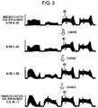
- FIG. 3 is a diagram illustrating transition over time of time series data of a torque value in one machining process.
- FIG. 4 is a conceptual diagram illustrating an example of a machining state variable (variance/standard deviation/root-mean-square (RMS)).
- RMS root-mean-square
- FIG. 5 is a conceptual diagram illustrating an example of the machining state variable (kurtosis).
- FIG. 6 is a conceptual diagram illustrating an example of the machining state variable (skewness).
- FIG. 7 is a conceptual diagram illustrating an example of the machining state variables (average value/maximum value/minimum value).
- FIG. 8 is a conceptual diagram illustrating an example of the machining state variable (distance from reference waveform).
- FIG. 9 is a conceptual diagram illustrating an example of the machining state variables (integral value/average load/cubic mean value).
- FIG. 10 is a diagram illustrating an example of tool deterioration state data.
- FIG. 11 is a diagram illustrating an example of a tool replacement timing threshold value.
- FIG. 12 is a diagram illustrating an example of a residual machining amount.
- FIG. 13 is a diagram illustrating an example of a tool deterioration state range.
- FIG. 14 is a diagram illustrating an example of a display screen of a display section.
- FIG. 1 is a block diagram of a tool replacement timing management system 1 in the present embodiment.
- the tool replacement timing management system 1 includes a machine 10 , a data acquisition section 11 , a data cutout section 12 , a machining state variable calculating section 13 , a tool deterioration state generation section 14 , and a tool replacement timing calculating section 15 .
- Constituent elements other than the machine 10 may be configured with hardware, such as an ASIC (application specific integrated circuit) and an FPGA (field-programmable gate array), or may be configured with software executed on a computer equipped with a CPU (central processing unit), a RAM (random access memory), a ROM (read only memory), and the like.
- the tool replacement timing management system 1 may be an all-in-one type in which the components are connected by bus connection or the like, or may be a distributed type in which the components are connected via a wired or wireless network.
- the machine 10 is a machine that performs machining on a workpiece by using a tool, and includes, for example, a machine tool, a robot, or the like. Machining contents of the machine 10 include, for example, cutting-off, cutting, drilling, chamfering, threading, and the like, and types of the workpiece include, for example, metal, wood, and the like. Types of the tool include, for example, a milling cutter such as an end mill, a drill, a reamer, a tap, and the like.
- the data acquisition section 11 acquires time series data indicating a machining state from the machine 10 .
- the time series data indicating the machining state may be, for example, a torque value of a servo motor provided in the machine 10 (e.g., a torque command value, a current value, and the like of each shaft), a detected value of a sensor separately installed on the machine 10 (e.g., detected values of a vibration sensor, a force sensor, and the like), a machine parameter such as a tool offset, or the like.
- FIG. 2 illustrates time series data 21 of a torque value in one machining process, as an example of time series data indicating a machining state.
- FIG. 3 illustrates a change in time series data of a torque value 40 in one machining process over time. While regularity of the change over time is difficult to see in appearance, by using a particular index to make trends visible, a tool replacement timing can be predicted.
- the data cutout section 12 cuts out specimen data 22 from the time series data 21 indicating a machining state, according to at least one condition or a combination of conditions selected from among machining, a tool, a workpiece, and a tool speed.
- the combination of conditions for the cutout means that each of the machining, the tool, the workpiece, and the tool speed is identical, or that at least one of the machining, the tool, the workpiece, and the tool speed is similar.
- Similar machining includes machining that performs similar machining contents even for machining for another purpose (e.g., cutting-off and cutting, drilling and threading, etc.), or machining that performs partially different machining contents even for machining for an identical purpose (e.g., cutting including rough cutting and precision cutting, and cutting including only precision cutting, etc.).
- a similar tool or workpiece includes a tool or workpiece with identical features even when the tool or workpiece is supplied from another supplier.
- a similar tool speed includes a tool speed within a predetermined range.
- the machining state variable calculating section 13 calculates a machining state variable, which is a statistical index, from the specimen data 22 .
- the machining state variable includes, for example, variance, standard deviation, RMS, kurtosis, skewness, average value, maximum value, minimum value, distance from reference waveform (average waveform), integral value, average load, cubic mean value, and the like.
- the machining state variable may be a value for which a change over time is the largest among these statistical indices, or may be a value selected from among these statistical indices, or a combination thereof (e.g., a multiplication value or the like) on a basis of preset priority levels.
- the priority levels can be preset as three stages, for example, as illustrated in a table below.
- Variance/standard deviation/RMS represent variations in the specimen data 22 .
- variance of the specimen data 22 is aligned in a time series from immediately after replacing a tool until before replacing the tool, the variance rises over time.
- Kurtosis for example, as illustrated in FIG. 5 , represents sharpness of the specimen data 22 .
- the kurtosis of the specimen data 22 is aligned in a time series from immediately after replacing a tool until before replacing the tool, the kurtosis lowers over time.
- Skewness for example, as illustrated in FIG. 6 , represents distortion of the specimen data 22 .
- the skewness of the specimen data 22 is aligned in a time series from immediately after replacing a tool until before replacing the tool, the skewness lowers over time as well.
- Average value/maximum value/minimum value are, for example, well known as illustrated in FIG. 7 , however, when the average value/maximum value/minimum value of the specimen data 22 are aligned in a time series from immediately after replacing a tool and until before replacing the tool, these values also rise over time.
- a distance from reference waveform represents a distance between the specimen data 22 and a reference waveform 23 .
- the reference waveform may be an average waveform of the specimen data 22 in a past.
- An integral value for example, as illustrated in FIG. 9 , represents a total integral value (cumulative value) of the specimen data 22 .
- This value rises over time as well.
- An average load F m is determined from a formula below, for example, where F n is a load at time t n , and n is a speed at time t n .
- the speed n is fixed (i.e., a constant) or falls within a certain range.
- F m F 1 ⁇ nt 1 + F 2 ⁇ n ⁇ t 2 + ... + F n ⁇ n ⁇ t n n ⁇ t 1 + n ⁇ t 2 + ... + n ⁇ t n
- a cubic mean value is a cubic mean of deviations from an average value, as is well known.
- the tool deterioration state generation section 14 generates tool deterioration state data in which the machining state variable is aligned in a time series, with a period from after replacing a tool until before replacing the tool being one cycle.
- FIG. 9 illustrates tool deterioration state data 24 in which the variance (a top graph) and the kurtosis (a bottom graph) are aligned in a time series.
- an actual tool replacement timing 25 is illustrated. It can be seen that, as the tool replacement timing 25 is approached, the variance rises and the kurtosis lowers.
- the tool replacement timing calculating section 15 calculates the tool replacement timing on a basis of the tool deterioration state data.
- the tool replacement timing calculating section 15 may calculate a tool replacement timing threshold value on a basis of the tool deterioration state data previously generated as illustrated in FIG. 11 , and calculate a tool replacement timing in tool deterioration state data newly generated.
- the tool replacement timing calculating section 15 desirably calculates a tool replacement timing threshold value on a basis of tool deterioration state data of a specific worker (e.g., a reliable skilled person).
- Examples of a method for calculating the tool replacement timing threshold value include, for example, techniques below.
- a maximum value of a machining state variable in one cycle is calculated as an average value averaged over a plurality of cycles.
- a machining state variable immediately before a change in the machining state variable in one cycle is maximized is calculated as an average value averaged over a plurality of cycles.
- An average value of a machining state variable at an identical time point over a plurality of cycles is calculated, as a maximum value in average tool deterioration state data aligned in a time series.
- FIG. 11 illustrates an example of a tool replacement timing threshold value 26 .
- This tool replacement timing threshold value 26 is calculated as a maximum value in average tool deterioration state data 27 .
- the tool replacement timing calculating section 15 calculates a time point when newly generated tool deterioration state data exceed the tool replacement timing threshold value 26 , as the tool replacement timing 25 .
- the tool replacement timing calculating section 15 may output a tool replacement signal to the machine 10 .
- the tool replacement signal can be utilized, for example, as an automatic tool replacement signal for the machine 10 , or as a tool replacement notification signal for a worker.
- the tool replacement timing management system 1 may further include a residual machining amount calculating section 16 .
- the residual machining amount calculating section 16 calculates a residual machining amount 28 on a basis of the tool deterioration state data 24 newly generated and the tool replacement timing threshold value 26 .
- the residual machining amount may be, for example, the number of residual machining times, a residual machining time, and the like.
- Examples of a method for calculating the residual machining amount include, for example, techniques below.
- a predicted approximate line of the tool deterioration state data 24 newly generated is determined, an intersection point of the predicted approximate line and the tool replacement timing threshold value 26 is calculated, and the residual machining amount 28 from current to the intersection point is calculated.
- the tool replacement timing management system 1 may further include a tool deterioration state range calculating section 17 , and an abnormality notification section 18 .
- the tool deterioration state range calculating section 17 calculates the average tool deterioration state data 27 as illustrated in FIG. 13 , and standard deviation tool deterioration state data (not illustrated) in which a standard deviation of a machining state variable at an identical time point over a plurality of cycles is aligned in a time series, and calculates a range obtained by adding and subtracting a predetermined multiple of the standard deviation tool deterioration state data to and from the average tool deterioration state data 27 as a tool deterioration state range 29 .
- the tool deterioration state data 24 newly generated are to fall within the tool deterioration state range 29 of ⁇ 1 ⁇ with a probability of 68%, fall within the tool deterioration state range 29 of ⁇ 2 ⁇ with a probability of 95%, and fall within the tool deterioration state range 29 of ⁇ 3 ⁇ with a probability of 99%.
- the abnormality notification section 18 When the tool deterioration state data 24 newly generated deviate from the tool deterioration state range 29 , the abnormality notification section 18 outputs an abnormality signal.
- the abnormality signal can be utilized, for example, as a power stop signal for the machine 10 , or as a tool check notification signal for the worker.
- the tool replacement timing management system 1 may further include a storage section 19 and a display section 20 .
- the storage section 19 includes, for example, memories such as a RAM (random access memory) and an SSD (solid state drive).
- the storage section 19 stores, for each of machining contents, types of workpiece, and types of tool, for example, time series data indicating a machining state, newly generated tool deterioration state data, a tool replacement timing threshold value, average tool deterioration state data, a residual machining amount, and the like.
- the display section 20 includes a display apparatus such as a liquid crystal display.
- the display section 20 for each of machining contents, types of workpiece, and types of tool, displays the time series data 21 indicating a machining state, the tool deterioration state data 24 newly generated, the tool replacement timing threshold value 26 , the average tool deterioration state data 27 , the residual machining amount 28 , and the like. This makes it possible to quantitatively view a tool deterioration state, an appropriate tool replacement timing, a residual machining amount, and the like.
- the tool deterioration state can be viewed quantitatively.
- accumulation of a tool replacement timing of a skilled person makes it possible to predict an appropriate tool replacement timing as well. Further, an appropriate tool replacement timing can be taught to an unskilled person.
Abstract
Description
| Machining State Variable | Priority Level (Three Stages) | ||
| Variance/Standard | 3 | ||
| Deviation/RMS | |||
| Kurtosis | 2 | ||
| Skewness | 1 | ||
| Average Value | 2 | ||
| |
1 | ||
| |
1 | ||
| Distance from Reference | 3 | ||
| Waveform | |||
| Integral Value | 2 | ||
| Average Load/Cubic Mean | 2 | ||
Claims (11)
Applications Claiming Priority (3)
| Application Number | Priority Date | Filing Date | Title |
|---|---|---|---|
| JP2019-064269 | 2019-03-28 | ||
| JP2019064269A JP7036763B2 (en) | 2019-03-28 | 2019-03-28 | Tool change timing management system |
| JPJP2019-064269 | 2019-03-28 |
Publications (2)
| Publication Number | Publication Date |
|---|---|
| US20200306913A1 US20200306913A1 (en) | 2020-10-01 |
| US11376701B2 true US11376701B2 (en) | 2022-07-05 |
Family
ID=72607751
Family Applications (1)
| Application Number | Title | Priority Date | Filing Date |
|---|---|---|---|
| US16/831,882 Active 2040-06-12 US11376701B2 (en) | 2019-03-28 | 2020-03-27 | Tool replacement timing management system |
Country Status (4)
| Country | Link |
|---|---|
| US (1) | US11376701B2 (en) |
| JP (1) | JP7036763B2 (en) |
| CN (1) | CN111754016A (en) |
| DE (1) | DE102020107861B4 (en) |
Families Citing this family (1)
| Publication number | Priority date | Publication date | Assignee | Title |
|---|---|---|---|---|
| CN113110296B (en) * | 2021-03-10 | 2022-09-23 | 广州明珞装备股份有限公司 | Cutter management method, system, equipment and storage medium based on intelligent processing station |
Citations (14)
| Publication number | Priority date | Publication date | Assignee | Title |
|---|---|---|---|---|
| JPH07132440A (en) | 1993-11-02 | 1995-05-23 | Fanuc Ltd | Machining load monitoring system |
| JPH1128646A (en) | 1997-07-07 | 1999-02-02 | Toshiba Mach Co Ltd | Method and device for determining tool replacement time, tool replacement time warning device, and tool replacement time control signal output device |
| JP2001205545A (en) | 2000-01-31 | 2001-07-31 | Toshiba Mach Co Ltd | Tool replacement timing judging system |
| US20030182014A1 (en) * | 2002-03-22 | 2003-09-25 | Mcdonnell Ryan P. | Tool wear monitoring system |
| JP2004130451A (en) | 2002-10-10 | 2004-04-30 | Toyota Motor Corp | Tool replacement timing indicating device |
| JP2006205289A (en) | 2005-01-27 | 2006-08-10 | Murata Mach Ltd | Tool service life predicting device |
| JP2008254080A (en) | 2007-04-02 | 2008-10-23 | Mitsubishi Electric Corp | Method and device for detecting life of machining tool |
| JP4919999B2 (en) | 2008-03-24 | 2012-04-18 | 三菱電機株式会社 | Tool life detection method and tool life detection device |
| JP5089618B2 (en) | 2009-01-13 | 2012-12-05 | 三菱電機株式会社 | Tool life detection method and tool life detection device |
| US20130195143A1 (en) * | 2012-01-31 | 2013-08-01 | Toshiba Kikai Kabushiki Kaisha | Method of measuring temperature in cutting process |
| JP2018103284A (en) | 2016-12-22 | 2018-07-05 | ファナック株式会社 | Tool life estimation device |
| JP6392843B2 (en) | 2016-12-28 | 2018-09-19 | ファナック株式会社 | Machine tool, production management system, and method for predicting and detecting tool life |
| JP2019030954A (en) | 2017-08-07 | 2019-02-28 | Dmg森精機株式会社 | Machine tool and method for calculating degree of abrasion of tool |
| US11017305B2 (en) * | 2017-06-29 | 2021-05-25 | Hcl Technologies Limited | System for alerting a user before a breakdown of a component present in a vehicle |
Family Cites Families (1)
| Publication number | Priority date | Publication date | Assignee | Title |
|---|---|---|---|---|
| JP6360432B2 (en) | 2014-12-16 | 2018-07-18 | Dmg森精機株式会社 | Step tool life management device |
-
2019
- 2019-03-28 JP JP2019064269A patent/JP7036763B2/en active Active
-
2020
- 2020-03-23 CN CN202010205856.8A patent/CN111754016A/en active Pending
- 2020-03-23 DE DE102020107861.7A patent/DE102020107861B4/en active Active
- 2020-03-27 US US16/831,882 patent/US11376701B2/en active Active
Patent Citations (14)
| Publication number | Priority date | Publication date | Assignee | Title |
|---|---|---|---|---|
| JPH07132440A (en) | 1993-11-02 | 1995-05-23 | Fanuc Ltd | Machining load monitoring system |
| JPH1128646A (en) | 1997-07-07 | 1999-02-02 | Toshiba Mach Co Ltd | Method and device for determining tool replacement time, tool replacement time warning device, and tool replacement time control signal output device |
| JP2001205545A (en) | 2000-01-31 | 2001-07-31 | Toshiba Mach Co Ltd | Tool replacement timing judging system |
| US20030182014A1 (en) * | 2002-03-22 | 2003-09-25 | Mcdonnell Ryan P. | Tool wear monitoring system |
| JP2004130451A (en) | 2002-10-10 | 2004-04-30 | Toyota Motor Corp | Tool replacement timing indicating device |
| JP2006205289A (en) | 2005-01-27 | 2006-08-10 | Murata Mach Ltd | Tool service life predicting device |
| JP2008254080A (en) | 2007-04-02 | 2008-10-23 | Mitsubishi Electric Corp | Method and device for detecting life of machining tool |
| JP4919999B2 (en) | 2008-03-24 | 2012-04-18 | 三菱電機株式会社 | Tool life detection method and tool life detection device |
| JP5089618B2 (en) | 2009-01-13 | 2012-12-05 | 三菱電機株式会社 | Tool life detection method and tool life detection device |
| US20130195143A1 (en) * | 2012-01-31 | 2013-08-01 | Toshiba Kikai Kabushiki Kaisha | Method of measuring temperature in cutting process |
| JP2018103284A (en) | 2016-12-22 | 2018-07-05 | ファナック株式会社 | Tool life estimation device |
| JP6392843B2 (en) | 2016-12-28 | 2018-09-19 | ファナック株式会社 | Machine tool, production management system, and method for predicting and detecting tool life |
| US11017305B2 (en) * | 2017-06-29 | 2021-05-25 | Hcl Technologies Limited | System for alerting a user before a breakdown of a component present in a vehicle |
| JP2019030954A (en) | 2017-08-07 | 2019-02-28 | Dmg森精機株式会社 | Machine tool and method for calculating degree of abrasion of tool |
Also Published As
| Publication number | Publication date |
|---|---|
| DE102020107861A1 (en) | 2020-10-01 |
| US20200306913A1 (en) | 2020-10-01 |
| JP7036763B2 (en) | 2022-03-15 |
| CN111754016A (en) | 2020-10-09 |
| DE102020107861B4 (en) | 2024-05-08 |
| JP2020163493A (en) | 2020-10-08 |
Similar Documents
| Publication | Publication Date | Title |
|---|---|---|
| US10493583B2 (en) | Detection device, detection method and compensation method for tool wear | |
| JP3686336B2 (en) | Method of creating tool wear data, estimating tool wear, and determining tool usage | |
| US20190210176A1 (en) | Abnormality-detecting device and method for tool of machine tool | |
| US20090030545A1 (en) | Numeric control device of machine tool | |
| JP4441735B2 (en) | Process monitoring method for cycle operation processing machine | |
| EP2821870B1 (en) | Setting method of revolutions per minute on real time of rotating cutting tool, and control device | |
| DE102015109237A1 (en) | Device for correcting a thermal offset for a work machine | |
| US20200089191A1 (en) | Method for monitoring cutting-tool abrasion | |
| KR101999112B1 (en) | Tool life maintenance system and tool life maintenance method for machine tools | |
| CN112091726A (en) | Abnormality detection device for machining tool | |
| EP3792712A1 (en) | Method for correcting the tool parameters of a machine tool for machining workpieces | |
| US7957821B2 (en) | Systems and methods for statistical process control | |
| US11376701B2 (en) | Tool replacement timing management system | |
| CN114918739B (en) | Machine tool spindle fault detection method, device, terminal and storage medium | |
| CN113325801B (en) | Ultra-precision machining system, method, apparatus, and storage medium | |
| US11440152B2 (en) | Machining environment measurement device | |
| CN105988417A (en) | Numerical control device inspecting screw holes | |
| JP6966166B2 (en) | Machine tool feed shaft operating status display device and operating status display method | |
| US11790700B2 (en) | Relearning necessity determination method and relearning necessity determination device of diagnostic model in machine tool, and computer readable medium | |
| DE102013011661B4 (en) | Control device for judging if machining is possible | |
| Jemielniak | Tool wear monitoring based on a non-monotonic signal feature | |
| JP6526583B2 (en) | Cutting machine monitoring device | |
| US4854161A (en) | Method for diagnosing cutting tool dullness | |
| JP2005022052A (en) | Method and device for detecting abnormality and service life of working tool | |
| CN115907606A (en) | Equipment management system and method based on big data |
Legal Events
| Date | Code | Title | Description |
|---|---|---|---|
| AS | Assignment |
Owner name: FANUC CORPORATION, JAPAN Free format text: ASSIGNMENT OF ASSIGNORS INTEREST;ASSIGNORS:KANIWA, YUKIO;HARA, NOBUHIRO;OOTSUKA, YUUKI;REEL/FRAME:052241/0818 Effective date: 20200107 |
|
| FEPP | Fee payment procedure |
Free format text: ENTITY STATUS SET TO UNDISCOUNTED (ORIGINAL EVENT CODE: BIG.); ENTITY STATUS OF PATENT OWNER: LARGE ENTITY |
|
| STPP | Information on status: patent application and granting procedure in general |
Free format text: APPLICATION DISPATCHED FROM PREEXAM, NOT YET DOCKETED |
|
| STPP | Information on status: patent application and granting procedure in general |
Free format text: DOCKETED NEW CASE - READY FOR EXAMINATION |
|
| STPP | Information on status: patent application and granting procedure in general |
Free format text: NON FINAL ACTION MAILED |
|
| STPP | Information on status: patent application and granting procedure in general |
Free format text: RESPONSE TO NON-FINAL OFFICE ACTION ENTERED AND FORWARDED TO EXAMINER |
|
| STPP | Information on status: patent application and granting procedure in general |
Free format text: NOTICE OF ALLOWANCE MAILED -- APPLICATION RECEIVED IN OFFICE OF PUBLICATIONS |
|
| STPP | Information on status: patent application and granting procedure in general |
Free format text: AWAITING TC RESP., ISSUE FEE NOT PAID |
|
| STPP | Information on status: patent application and granting procedure in general |
Free format text: NOTICE OF ALLOWANCE MAILED -- APPLICATION RECEIVED IN OFFICE OF PUBLICATIONS |
|
| STPP | Information on status: patent application and granting procedure in general |
Free format text: PUBLICATIONS -- ISSUE FEE PAYMENT VERIFIED |
|
| STCF | Information on status: patent grant |
Free format text: PATENTED CASE |