US11373159B2 - Payment terminal - Google Patents
Payment terminal Download PDFInfo
- Publication number
- US11373159B2 US11373159B2 US16/760,200 US201816760200A US11373159B2 US 11373159 B2 US11373159 B2 US 11373159B2 US 201816760200 A US201816760200 A US 201816760200A US 11373159 B2 US11373159 B2 US 11373159B2
- Authority
- US
- United States
- Prior art keywords
- payment terminal
- payment
- terminal according
- terminal
- housing
- Prior art date
- Legal status (The legal status is an assumption and is not a legal conclusion. Google has not performed a legal analysis and makes no representation as to the accuracy of the status listed.)
- Active, expires
Links
Images


Classifications
-
- G—PHYSICS
- G06—COMPUTING; CALCULATING OR COUNTING
- G06K—GRAPHICAL DATA READING; PRESENTATION OF DATA; RECORD CARRIERS; HANDLING RECORD CARRIERS
- G06K7/00—Methods or arrangements for sensing record carriers, e.g. for reading patterns
- G06K7/0004—Hybrid readers
-
- G—PHYSICS
- G06—COMPUTING; CALCULATING OR COUNTING
- G06Q—INFORMATION AND COMMUNICATION TECHNOLOGY [ICT] SPECIALLY ADAPTED FOR ADMINISTRATIVE, COMMERCIAL, FINANCIAL, MANAGERIAL OR SUPERVISORY PURPOSES; SYSTEMS OR METHODS SPECIALLY ADAPTED FOR ADMINISTRATIVE, COMMERCIAL, FINANCIAL, MANAGERIAL OR SUPERVISORY PURPOSES, NOT OTHERWISE PROVIDED FOR
- G06Q20/00—Payment architectures, schemes or protocols
- G06Q20/08—Payment architectures
- G06Q20/20—Point-of-sale [POS] network systems
- G06Q20/204—Point-of-sale [POS] network systems comprising interface for record bearing medium or carrier for electronic funds transfer or payment credit
-
- G—PHYSICS
- G06—COMPUTING; CALCULATING OR COUNTING
- G06F—ELECTRIC DIGITAL DATA PROCESSING
- G06F1/00—Details not covered by groups G06F3/00 - G06F13/00 and G06F21/00
- G06F1/16—Constructional details or arrangements
- G06F1/1613—Constructional details or arrangements for portable computers
- G06F1/1633—Constructional details or arrangements of portable computers not specific to the type of enclosures covered by groups G06F1/1615 - G06F1/1626
- G06F1/1684—Constructional details or arrangements related to integrated I/O peripherals not covered by groups G06F1/1635 - G06F1/1675
- G06F1/1686—Constructional details or arrangements related to integrated I/O peripherals not covered by groups G06F1/1635 - G06F1/1675 the I/O peripheral being an integrated camera
-
- G—PHYSICS
- G06—COMPUTING; CALCULATING OR COUNTING
- G06F—ELECTRIC DIGITAL DATA PROCESSING
- G06F1/00—Details not covered by groups G06F3/00 - G06F13/00 and G06F21/00
- G06F1/16—Constructional details or arrangements
- G06F1/1613—Constructional details or arrangements for portable computers
- G06F1/1633—Constructional details or arrangements of portable computers not specific to the type of enclosures covered by groups G06F1/1615 - G06F1/1626
- G06F1/1684—Constructional details or arrangements related to integrated I/O peripherals not covered by groups G06F1/1635 - G06F1/1675
- G06F1/1698—Constructional details or arrangements related to integrated I/O peripherals not covered by groups G06F1/1635 - G06F1/1675 the I/O peripheral being a sending/receiving arrangement to establish a cordless communication link, e.g. radio or infrared link, integrated cellular phone
-
- G—PHYSICS
- G06—COMPUTING; CALCULATING OR COUNTING
- G06K—GRAPHICAL DATA READING; PRESENTATION OF DATA; RECORD CARRIERS; HANDLING RECORD CARRIERS
- G06K7/00—Methods or arrangements for sensing record carriers, e.g. for reading patterns
- G06K7/10—Methods or arrangements for sensing record carriers, e.g. for reading patterns by electromagnetic radiation, e.g. optical sensing; by corpuscular radiation
- G06K7/10009—Methods or arrangements for sensing record carriers, e.g. for reading patterns by electromagnetic radiation, e.g. optical sensing; by corpuscular radiation sensing by radiation using wavelengths larger than 0.1 mm, e.g. radio-waves or microwaves
- G06K7/10297—Methods or arrangements for sensing record carriers, e.g. for reading patterns by electromagnetic radiation, e.g. optical sensing; by corpuscular radiation sensing by radiation using wavelengths larger than 0.1 mm, e.g. radio-waves or microwaves arrangements for handling protocols designed for non-contact record carriers such as RFIDs NFCs, e.g. ISO/IEC 14443 and 18092
-
- G—PHYSICS
- G06—COMPUTING; CALCULATING OR COUNTING
- G06K—GRAPHICAL DATA READING; PRESENTATION OF DATA; RECORD CARRIERS; HANDLING RECORD CARRIERS
- G06K7/00—Methods or arrangements for sensing record carriers, e.g. for reading patterns
- G06K7/10—Methods or arrangements for sensing record carriers, e.g. for reading patterns by electromagnetic radiation, e.g. optical sensing; by corpuscular radiation
- G06K7/10009—Methods or arrangements for sensing record carriers, e.g. for reading patterns by electromagnetic radiation, e.g. optical sensing; by corpuscular radiation sensing by radiation using wavelengths larger than 0.1 mm, e.g. radio-waves or microwaves
- G06K7/10316—Methods or arrangements for sensing record carriers, e.g. for reading patterns by electromagnetic radiation, e.g. optical sensing; by corpuscular radiation sensing by radiation using wavelengths larger than 0.1 mm, e.g. radio-waves or microwaves using at least one antenna particularly designed for interrogating the wireless record carriers
-
- G—PHYSICS
- G06—COMPUTING; CALCULATING OR COUNTING
- G06K—GRAPHICAL DATA READING; PRESENTATION OF DATA; RECORD CARRIERS; HANDLING RECORD CARRIERS
- G06K7/00—Methods or arrangements for sensing record carriers, e.g. for reading patterns
- G06K7/10—Methods or arrangements for sensing record carriers, e.g. for reading patterns by electromagnetic radiation, e.g. optical sensing; by corpuscular radiation
- G06K7/10544—Methods or arrangements for sensing record carriers, e.g. for reading patterns by electromagnetic radiation, e.g. optical sensing; by corpuscular radiation by scanning of the records by radiation in the optical part of the electromagnetic spectrum
- G06K7/10821—Methods or arrangements for sensing record carriers, e.g. for reading patterns by electromagnetic radiation, e.g. optical sensing; by corpuscular radiation by scanning of the records by radiation in the optical part of the electromagnetic spectrum further details of bar or optical code scanning devices
- G06K7/10861—Methods or arrangements for sensing record carriers, e.g. for reading patterns by electromagnetic radiation, e.g. optical sensing; by corpuscular radiation by scanning of the records by radiation in the optical part of the electromagnetic spectrum further details of bar or optical code scanning devices sensing of data fields affixed to objects or articles, e.g. coded labels
-
- G—PHYSICS
- G06—COMPUTING; CALCULATING OR COUNTING
- G06K—GRAPHICAL DATA READING; PRESENTATION OF DATA; RECORD CARRIERS; HANDLING RECORD CARRIERS
- G06K7/00—Methods or arrangements for sensing record carriers, e.g. for reading patterns
- G06K7/10—Methods or arrangements for sensing record carriers, e.g. for reading patterns by electromagnetic radiation, e.g. optical sensing; by corpuscular radiation
- G06K7/14—Methods or arrangements for sensing record carriers, e.g. for reading patterns by electromagnetic radiation, e.g. optical sensing; by corpuscular radiation using light without selection of wavelength, e.g. sensing reflected white light
- G06K7/1404—Methods for optical code recognition
- G06K7/1408—Methods for optical code recognition the method being specifically adapted for the type of code
- G06K7/1417—2D bar codes
-
- G—PHYSICS
- G06—COMPUTING; CALCULATING OR COUNTING
- G06Q—INFORMATION AND COMMUNICATION TECHNOLOGY [ICT] SPECIALLY ADAPTED FOR ADMINISTRATIVE, COMMERCIAL, FINANCIAL, MANAGERIAL OR SUPERVISORY PURPOSES; SYSTEMS OR METHODS SPECIALLY ADAPTED FOR ADMINISTRATIVE, COMMERCIAL, FINANCIAL, MANAGERIAL OR SUPERVISORY PURPOSES, NOT OTHERWISE PROVIDED FOR
- G06Q20/00—Payment architectures, schemes or protocols
- G06Q20/08—Payment architectures
- G06Q20/20—Point-of-sale [POS] network systems
- G06Q20/203—Inventory monitoring
-
- G—PHYSICS
- G06—COMPUTING; CALCULATING OR COUNTING
- G06Q—INFORMATION AND COMMUNICATION TECHNOLOGY [ICT] SPECIALLY ADAPTED FOR ADMINISTRATIVE, COMMERCIAL, FINANCIAL, MANAGERIAL OR SUPERVISORY PURPOSES; SYSTEMS OR METHODS SPECIALLY ADAPTED FOR ADMINISTRATIVE, COMMERCIAL, FINANCIAL, MANAGERIAL OR SUPERVISORY PURPOSES, NOT OTHERWISE PROVIDED FOR
- G06Q20/00—Payment architectures, schemes or protocols
- G06Q20/08—Payment architectures
- G06Q20/20—Point-of-sale [POS] network systems
- G06Q20/208—Input by product or record sensing, e.g. weighing or scanner processing
-
- G—PHYSICS
- G06—COMPUTING; CALCULATING OR COUNTING
- G06Q—INFORMATION AND COMMUNICATION TECHNOLOGY [ICT] SPECIALLY ADAPTED FOR ADMINISTRATIVE, COMMERCIAL, FINANCIAL, MANAGERIAL OR SUPERVISORY PURPOSES; SYSTEMS OR METHODS SPECIALLY ADAPTED FOR ADMINISTRATIVE, COMMERCIAL, FINANCIAL, MANAGERIAL OR SUPERVISORY PURPOSES, NOT OTHERWISE PROVIDED FOR
- G06Q20/00—Payment architectures, schemes or protocols
- G06Q20/30—Payment architectures, schemes or protocols characterised by the use of specific devices or networks
- G06Q20/32—Payment architectures, schemes or protocols characterised by the use of specific devices or networks using wireless devices
- G06Q20/322—Aspects of commerce using mobile devices [M-devices]
-
- G—PHYSICS
- G06—COMPUTING; CALCULATING OR COUNTING
- G06Q—INFORMATION AND COMMUNICATION TECHNOLOGY [ICT] SPECIALLY ADAPTED FOR ADMINISTRATIVE, COMMERCIAL, FINANCIAL, MANAGERIAL OR SUPERVISORY PURPOSES; SYSTEMS OR METHODS SPECIALLY ADAPTED FOR ADMINISTRATIVE, COMMERCIAL, FINANCIAL, MANAGERIAL OR SUPERVISORY PURPOSES, NOT OTHERWISE PROVIDED FOR
- G06Q20/00—Payment architectures, schemes or protocols
- G06Q20/30—Payment architectures, schemes or protocols characterised by the use of specific devices or networks
- G06Q20/32—Payment architectures, schemes or protocols characterised by the use of specific devices or networks using wireless devices
- G06Q20/327—Short range or proximity payments by means of M-devices
-
- G—PHYSICS
- G06—COMPUTING; CALCULATING OR COUNTING
- G06Q—INFORMATION AND COMMUNICATION TECHNOLOGY [ICT] SPECIALLY ADAPTED FOR ADMINISTRATIVE, COMMERCIAL, FINANCIAL, MANAGERIAL OR SUPERVISORY PURPOSES; SYSTEMS OR METHODS SPECIALLY ADAPTED FOR ADMINISTRATIVE, COMMERCIAL, FINANCIAL, MANAGERIAL OR SUPERVISORY PURPOSES, NOT OTHERWISE PROVIDED FOR
- G06Q20/00—Payment architectures, schemes or protocols
- G06Q20/30—Payment architectures, schemes or protocols characterised by the use of specific devices or networks
- G06Q20/34—Payment architectures, schemes or protocols characterised by the use of specific devices or networks using cards, e.g. integrated circuit [IC] cards or magnetic cards
- G06Q20/341—Active cards, i.e. cards including their own processing means, e.g. including an IC or chip
-
- G—PHYSICS
- G06—COMPUTING; CALCULATING OR COUNTING
- G06Q—INFORMATION AND COMMUNICATION TECHNOLOGY [ICT] SPECIALLY ADAPTED FOR ADMINISTRATIVE, COMMERCIAL, FINANCIAL, MANAGERIAL OR SUPERVISORY PURPOSES; SYSTEMS OR METHODS SPECIALLY ADAPTED FOR ADMINISTRATIVE, COMMERCIAL, FINANCIAL, MANAGERIAL OR SUPERVISORY PURPOSES, NOT OTHERWISE PROVIDED FOR
- G06Q20/00—Payment architectures, schemes or protocols
- G06Q20/30—Payment architectures, schemes or protocols characterised by the use of specific devices or networks
- G06Q20/34—Payment architectures, schemes or protocols characterised by the use of specific devices or networks using cards, e.g. integrated circuit [IC] cards or magnetic cards
- G06Q20/352—Contactless payments by cards
-
- G—PHYSICS
- G07—CHECKING-DEVICES
- G07F—COIN-FREED OR LIKE APPARATUS
- G07F7/00—Mechanisms actuated by objects other than coins to free or to actuate vending, hiring, coin or paper currency dispensing or refunding apparatus
- G07F7/08—Mechanisms actuated by objects other than coins to free or to actuate vending, hiring, coin or paper currency dispensing or refunding apparatus by coded identity card or credit card or other personal identification means
- G07F7/0873—Details of the card reader
- G07F7/0893—Details of the card reader the card reader reading the card in a contactless manner
-
- G—PHYSICS
- G06—COMPUTING; CALCULATING OR COUNTING
- G06F—ELECTRIC DIGITAL DATA PROCESSING
- G06F3/00—Input arrangements for transferring data to be processed into a form capable of being handled by the computer; Output arrangements for transferring data from processing unit to output unit, e.g. interface arrangements
- G06F3/01—Input arrangements or combined input and output arrangements for interaction between user and computer
- G06F3/03—Arrangements for converting the position or the displacement of a member into a coded form
- G06F3/033—Pointing devices displaced or positioned by the user, e.g. mice, trackballs, pens or joysticks; Accessories therefor
- G06F3/0354—Pointing devices displaced or positioned by the user, e.g. mice, trackballs, pens or joysticks; Accessories therefor with detection of 2D relative movements between the device, or an operating part thereof, and a plane or surface, e.g. 2D mice, trackballs, pens or pucks
- G06F3/03545—Pens or stylus
-
- G—PHYSICS
- G06—COMPUTING; CALCULATING OR COUNTING
- G06F—ELECTRIC DIGITAL DATA PROCESSING
- G06F3/00—Input arrangements for transferring data to be processed into a form capable of being handled by the computer; Output arrangements for transferring data from processing unit to output unit, e.g. interface arrangements
- G06F3/01—Input arrangements or combined input and output arrangements for interaction between user and computer
- G06F3/048—Interaction techniques based on graphical user interfaces [GUI]
- G06F3/0484—Interaction techniques based on graphical user interfaces [GUI] for the control of specific functions or operations, e.g. selecting or manipulating an object, an image or a displayed text element, setting a parameter value or selecting a range
- G06F3/04842—Selection of displayed objects or displayed text elements
-
- G—PHYSICS
- G06—COMPUTING; CALCULATING OR COUNTING
- G06F—ELECTRIC DIGITAL DATA PROCESSING
- G06F3/00—Input arrangements for transferring data to be processed into a form capable of being handled by the computer; Output arrangements for transferring data from processing unit to output unit, e.g. interface arrangements
- G06F3/01—Input arrangements or combined input and output arrangements for interaction between user and computer
- G06F3/048—Interaction techniques based on graphical user interfaces [GUI]
- G06F3/0487—Interaction techniques based on graphical user interfaces [GUI] using specific features provided by the input device, e.g. functions controlled by the rotation of a mouse with dual sensing arrangements, or of the nature of the input device, e.g. tap gestures based on pressure sensed by a digitiser
- G06F3/0488—Interaction techniques based on graphical user interfaces [GUI] using specific features provided by the input device, e.g. functions controlled by the rotation of a mouse with dual sensing arrangements, or of the nature of the input device, e.g. tap gestures based on pressure sensed by a digitiser using a touch-screen or digitiser, e.g. input of commands through traced gestures
- G06F3/04886—Interaction techniques based on graphical user interfaces [GUI] using specific features provided by the input device, e.g. functions controlled by the rotation of a mouse with dual sensing arrangements, or of the nature of the input device, e.g. tap gestures based on pressure sensed by a digitiser using a touch-screen or digitiser, e.g. input of commands through traced gestures by partitioning the display area of the touch-screen or the surface of the digitising tablet into independently controllable areas, e.g. virtual keyboards or menus
-
- G—PHYSICS
- G06—COMPUTING; CALCULATING OR COUNTING
- G06K—GRAPHICAL DATA READING; PRESENTATION OF DATA; RECORD CARRIERS; HANDLING RECORD CARRIERS
- G06K7/00—Methods or arrangements for sensing record carriers, e.g. for reading patterns
- G06K7/10—Methods or arrangements for sensing record carriers, e.g. for reading patterns by electromagnetic radiation, e.g. optical sensing; by corpuscular radiation
- G06K2007/10504—Data fields affixed to objects or articles
-
- G—PHYSICS
- G06—COMPUTING; CALCULATING OR COUNTING
- G06Q—INFORMATION AND COMMUNICATION TECHNOLOGY [ICT] SPECIALLY ADAPTED FOR ADMINISTRATIVE, COMMERCIAL, FINANCIAL, MANAGERIAL OR SUPERVISORY PURPOSES; SYSTEMS OR METHODS SPECIALLY ADAPTED FOR ADMINISTRATIVE, COMMERCIAL, FINANCIAL, MANAGERIAL OR SUPERVISORY PURPOSES, NOT OTHERWISE PROVIDED FOR
- G06Q30/00—Commerce
- G06Q30/02—Marketing; Price estimation or determination; Fundraising
- G06Q30/0241—Advertisements
- G06Q30/0251—Targeted advertisements
- G06Q30/0262—Targeted advertisements during computer stand-by mode
-
- G—PHYSICS
- G06—COMPUTING; CALCULATING OR COUNTING
- G06Q—INFORMATION AND COMMUNICATION TECHNOLOGY [ICT] SPECIALLY ADAPTED FOR ADMINISTRATIVE, COMMERCIAL, FINANCIAL, MANAGERIAL OR SUPERVISORY PURPOSES; SYSTEMS OR METHODS SPECIALLY ADAPTED FOR ADMINISTRATIVE, COMMERCIAL, FINANCIAL, MANAGERIAL OR SUPERVISORY PURPOSES, NOT OTHERWISE PROVIDED FOR
- G06Q30/00—Commerce
- G06Q30/06—Buying, selling or leasing transactions
- G06Q30/0601—Electronic shopping [e-shopping]
- G06Q30/0631—Item recommendations
Definitions
- the present invention concerns the field of devices for reading electronic cards and, in particular, a payment terminal.
- Electronic payment devices are, like the Internet, the most commonly used means for making transactions. Specifically, the transactions or the payment are made using a credit card and the majority of payments by credit card are made either in stores using a point-of-sale terminal where you insert or swipe your credit card and identify yourself with a Personal Identification Number, PIN, or over the Internet using a computer where you enter the details of your credit card and, in some cases, also a security code.
- the present invention has as its object to obviate certain drawback of the prior art by offering a means for ensuring transactions and taking advantage of advances in digital technology.
- a payment terminal with a housing comprising a planar upper face with an extension at one end forming an angle ⁇ 2 between 30 and 50° with the planar face for receiving a contactless reading device for contactless reading and communicating with contactless payment means, the other end of the planar face comprising a magnetic stripe card reader and receiving, in a slot, located above the magnetic stripe card reader and forming an angle ⁇ 1 between 30 and 50° with the planar face, a contact chip card reader, said terminal comprising a main circuit board comprising at least a controller, at least a memory for storing data and/or programs, said controller comprising at least a processor for executing said programs when it receives instructions from the memory of the controller in order to control at least a display device displaying a virtual keyboard, means for communicating by Internet or by WiFi, and a functionality of contact or contactless card reading, the terminal being characterized in that said main circuit board comprises, at one end, a connector for a contact card reader oriented with an angle ⁇ 1 between 30 and 50
- the memory of said main circuit board also comprises at least a program, the execution of which implements a “device tree” functionality, said functionality allowing the association of at least a set of devices with said terminal, said devices being controlled by the processor of said main circuit board.
- said housing comprises a lower face opposite the planar upper face and comprising at least:
- the cavity of the lower face of said terminal comprises at least a SIM card slot for the 4G and/or 3G wireless connection of said payment terminal to the Internet, a micro-SD slot for recording data and at least a secure access module (SAM) slot for receiving at least a SAM card which manages the secure access to the functionality of said payment terminal.
- SIM card slot for the 4G and/or 3G wireless connection of said payment terminal to the Internet
- micro-SD slot for recording data
- SAM secure access module
- the display device is an interactive touch-screen for displaying at least information such as icons or a button and comprising a virtual keyboard allowing a user to enter information or to make a selection of one or more icons to trigger a functionality or an application.
- the interactive touch-screen comprises at least a light sensor for the automatic adaptation of the contrast of the display.
- the interactive touch-screen comprises at least an accelerometer for the automatic orientation of the user interface in landscape mode or in portrait mode as a function of the orientation of the payment terminal.
- planar upper face comprises at least:
- the camera starts to record the events when a user interacts with the screen ( 14 ) of said payment terminal, the recording functionality of the camera being automatically turned on.
- the camera stops recording when no user interacts with said screen of said payment terminal during a predetermined time, the recording functionality being automatically turned off.
- said camera is adapted for reading tags or QR codes comprising information concerning a product via a scanning functionality included in said camera.
- the payment terminal comprises a second camera located at the upper end of at least one lateral face of the housing of said payment terminal or at the lower face of said terminal.
- the memory of the controller comprises at least a program, the execution of which enables to implement the functionality of triggering and recording of the camera.
- the housing of the payment terminal also comprises at least one lateral face comprising a hole comprising at least a headphone socket for audio guiding during the plugging-in of a headphone and an accessibility control switch for increasing at least the contrast of the display or the font size used.
- the end of said planar surface comprising the slot of the chip card reader, comprises at least a speaker for guiding a user.
- the housing of the payment terminal comprises, on a lateral face opposite said at least one lateral face comprising the headphone socket, a physical safety slot for receiving at least a lock which prevents the removal of a component of said payment terminal.
- At least one lateral face of the housing of said payment terminal comprises at least a USB port allowing the connection of said terminal to at least a computer device or a smartphone, said computer device comprising at least wireless communicating means for configuring and communicating with the payment terminal.
- the payment terminal is configured by said computer device or transfers at least information and/or data associated with a payment process to said computer device or vice versa by means of the connection.
- the payment terminal is configured by the computer device to at least:
- the lower face of the payment terminal comprises a reset button for resetting the configuration of the terminal, when said terminal is malfunctioning, a reset confirmation being requested on the screen of said terminal, when said reset button is enabled, in order to avoid the configuration of the terminal being automatically reset if said reset button is accidentally enabled.
- the housing of the payment terminal comprises, on at least one of its lateral faces, a location for attaching a touch-sensitive pen, said pen being used to interact with the screen of said payment terminal.
- the payment terminal comprises attaching means for cooperating with an attachment plate orienting the planar upper face of the terminal in such a way that the orientation of the chip card reader is such that said card forms an angle:
- the payment terminal records information concerning at least one product that a customer usually purchases, said information being stored in a secure database with which said terminal communicates using its communicating means.
- the payment terminal is adapted for displaying information stored in the secure database and associated with said product when a product purchased by a customer is nearly out of stock.
- the payment terminal is adapted for connecting to the secure database or to the Internet, by a secure access, and searches for information concerning products and their availability on markets or in shopping centers in the neighborhood, said information being displayed on the screen of said terminal and suggested to the customer.
- the payment terminal is adapted for displaying advertisements for a shopping center, to a cinema, a sports center or any other entertainment center when it is in standby mode.
- the accessibility control switch of the payment terminal enables to remove the advertisements displayed on the screen of the payment terminal.
- the contactless payment means comprise at least a chip card or other devices comprising a smartphone or other mobile devices.
- Another object of the present invention consists in proposing an infrastructure for transactions.
- a payment system comprising a connector housing (ITF) cooperating with the terminal as described in the present application, said connector housing being configured to be housed in the cavity of the lower face of said terminal and comprising at least an electrical power inlet socket, an Ethernet port, a USB port and at least a USB host to allow said payment terminal to communicate with at least a device configured on the “device tree”.
- ITF connector housing
- Another object of the present invention consists in proposing a secure and nomadic payment device.
- a portable payment terminal comprising a battery housing cooperating with said payment terminal ( 1 ) as described in the present application, said housing being configured to be housed in the cavity of the lower face of said payment terminal and comprising at least a battery, a power supply inlet socket and a micro USB device.
- FIGS. 1 a and 1 b are respectively schematic representations of the perspective view of the front face of the payment device according to an embodiment and of a terminal cooperating with an attachment plate and with the chip card reader and the contactless card reader surface of said terminal respectively forming an angle ⁇ 1 and ⁇ 2 with respect to the planar upper face of said terminal according to an embodiment;
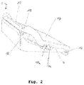
- FIG. 2 is a schematic representation of a rear profile view of the payment device, according to an embodiment
- FIG. 3 is a schematic representation of the lower face or rear side of the payment device according to an embodiment
- FIGS. 4 a and 4 b are respectively schematic representations of the cross-sections of a payment terminal comprising a battery housing according to an embodiment and a connector housing according to another embodiment;
- FIG. 5 is a schematic representation of the payment terminal cooperating respectively with a connector housing ((a) and (b)) according to an embodiment and with a battery housing ((c) and (d)), according to another embodiment;
- FIGS. 6 a and 6 b and 6 c are schematic representations of the payment terminal cooperating with an attachment plate according to an embodiment
- FIGS. 7 a and 7 b are schematic representations of a support cooperating with a payment terminal, with, respectively, the chip card reader located at the top of said support according to an embodiment and the chip card reader located at the bottom of said support according to another embodiment.
- the present invention relates to a terminal ( 1 , FIG. 1 a ) for the payment in a transaction.
- the payment terminal ( 1 ) includes a housing ( 10 ) comprising a planar upper face with an extension at one end forming an angle ⁇ 2 (see FIG. 1 b ) between 30 and 50° with the planar face for receiving a contactless reading device ( 121 ) for contactless reading and communicating with contactless payment means.
- the angle ⁇ 2 is 45°.
- the other end of the planar face comprises a magnetic stripe card reader ( 11 ) and receives, in a slot ( 13 ), located above the magnetic stripe card reader ( 11 ) and also forming an angle ⁇ 1 between 30 and 50° with the planar face, a contact chip card reader, said terminal ( 1 ) comprising a main circuit board ( 1030 ) comprising at least a controller, at least a memory for storing data and/or programs.
- the controller comprises at least a processor for executing said programs when it receives instructions from the memory of the controller in order to control at least a display device ( 14 ) displaying a virtual keyboard, means for communicating by Internet or by WiFi, and a functionality of contact or contactless card reading.
- the angle ⁇ 1 of the contact card reader with the planar face is 45° and is identical to that of the extension.
- the main circuit board ( 1030 ) of the terminal ( 1 ) comprises, at one end, a connector for the contact card oriented with an angle ⁇ 1 between 30 and 50°, preferably 45°, with the planar surface of the card and, at the other end, a flexible connector for connecting a wired antenna ( 120 ) for a functionality of reading of contactless payment means with an angle ⁇ 2 between 30 and 50°, preferably 45°, with the planar surface of the card.
- the display device ( 14 , FIG. 1 a ) is an interactive touch-screen ( 14 ) for displaying at least information such as icons or a button and comprising a virtual keyboard allowing a user to enter information or make a selection of one or more icons to trigger a functionality or an application.
- contactless reading device denotes any reading device (payment means) which does not require direct contact with the payment means (reading device) in order to communicate at least information by means of RFID (Radio-Frequency IDentification) or NFC (Near Field Communication) technology for making secure payments.
- RFID Radio-Frequency IDentification
- NFC Near Field Communication
- contactless payment means refers to a chip card (credit card, debit card or smart card) or to other devices comprising a smartphone and other mobile devices.
- the memory of said main circuit board ( 1030 ; FIGS. 4 a and 4 b ) also comprises at least a program, the execution of which implements a “device tree” functionality, said functionality allowing the association of at least a set of devices to said terminal ( 1 ), said devices being controlled by the processor of said main circuit board ( 1030 ).
- the devices managed by the “device tree” can be, for example and without limitation, a computer, a mobile phone or a USB device.
- the “device tree” can be configured by means of a program in order to allow more devices or hardware items to interact with said payment terminal ( 1 ).
- the main circuit board ( 1030 ) can also comprise at least a Bluetooth module, for example and without limitation, a BLE 4.2 module, for the connection of said terminal ( 1 ) to another terminal or to a device comprising Bluetooth technology.
- Said wireless communicating means can be used to exchange data for example.
- the terminal comprises an authentication/authorization program or software for securely configuring the “device tree” such that said “device tree” blocks access to all devices or hardware items not featuring on a stored list of devices or hardware items authorized to interact with said terminal.
- the terminal can comprise an alarm to emit a signal when an unauthorized device is not recognized by the “device tree”.
- the terminal may comprise a program, the execution of which on its processor enables to implement a method for securing the payment terminal ( 1 ) when the latter has to interact with an external device (for example a computer or a tablet), said method comprising at least:
- the housing ( 10 ) of the payment terminal ( 1 ) comprises a lower face opposite the planar upper face as shown in FIG. 3 .
- Said lower face comprises at least:
- the cavity ( 102 ) of the lower face of said terminal comprises at least a SIM card slot ( 1020 c ) for the 4G and/or 3G wireless connection of said payment terminal to the Internet, a micro-SD slot ( 1020 a ) for recording data and at least a secure access module (SAM) slot ( 1020 b ) for receiving at least a SAM card which manages the secure access to the functionality of said payment terminal.
- the SAM card is integrated into the main circuit board. ( 1030 ).
- the SAM card can be either a SIM card and be plugged into the location for SAM cards, or a fixed integrated circuit in a housing directly soldered onto the main circuit board.
- the SAM card manages all the key management and cryptography in a secure manner.
- SAM cards can be used at least:
- the set of retention means comprises at least flexible attachment lips.
- planar upper face of said payment terminal ( 1 ) comprises at least:
- the information displayed by the interactive touch-screen can be, for example and without limitation, the amount of a given transaction made by the user, a set of instructions for performing said transactions such as for example “Enter your password” etc.
- the display device ( 14 ) or the interactive touch-screen comprises at least a light sensor for the automatic adaptation of the contrast of the display.
- the display device ( 14 ) or the interactive touch-screen comprises at least an accelerometer for the automatic orientation of the user interface in landscape mode or in portrait mode as a function of the orientation of the payment terminal ( 1 ).
- the camera ( 15 ) is, preferably, located in the upper part of said interactive touch-screen.
- the recorded events can be used to secure the transactions or to prevent fraudulent actions.
- the events recorded by the camera ( 15 ) and associated with a given payment card can be stored in a memory or a server, using the communicating means, with at least an identification number making it possible to link said card to said events.
- an incorrect password entered more than a predetermined number of times or an amount greater than a daily threshold value the latter event can be compared to preceding events, associated with said card, in which the transactions have been made successfully, in order to check, for example, that the user or users are the same and that no other person is using said payment card.
- the recording of events by the camera ( 15 ) is triggered when a user interacts with the screen ( 14 ) of said payment terminal ( 1 ). Specifically, when a user interacts with said payment terminal ( 1 ), the recording functionality of the camera ( 15 ) is automatically turned on and said camera ( 15 ) starts the recording of the events. When no used interacts with said screen ( 14 ) of said payment terminal ( 1 ) for a predetermined time, said recording functionality is automatically turned off.
- the functionality of triggering and recording the camera ( 15 ) is implemented by the execution, on said processor, of at least a program included in the memory of the controller.
- the camera ( 15 ) is adapted for reading tags or QR codes comprising information concerning a product via a scanning functionality included in said camera ( 15 ).
- the payment terminal comprises a second camera ( 15 ) located at the upper end of at least one lateral face of the housing ( 10 ) of said payment terminal ( 1 ) as illustrated in said FIG. 2 .
- the second camera may be located at the lower face of said terminal as shown in FIG. 3 .
- the housing ( 10 ) of the payment terminal ( 1 ) also comprises at least one lateral face comprising a hole comprising at least a socket for a headphone ( 19 a , FIG. 2 ) for audio guiding during the plugging-in of a headphone and an accessibility control switch ( 19 b ) for increasing at least the contrast of the display or the font size used.
- the socket for the headphone may be used for the audio guiding of visually impaired persons.
- the accessibility control switch on another side, may be used for increasing the contrast of the display for visually impaired persons.
- the end of said planar surface comprising the chip card reader location ( 13 ), comprises at least a speaker ( 16 , FIG. 1 a ) for guiding a user.
- the housing ( 10 ) of the payment terminal ( 1 ) comprises, on a lateral face opposite said at least one lateral face comprising the headphone socket, a physical security slot ( 18 , FIG. 1 a ) for receiving at least a lock that prevents the removal of a component of said payment terminal ( 1 ).
- the physical security slot ( 18 ) is a slot of Kensington type.
- the terminal comprises a powering-up button located near the security slot ( 18 ).
- At least one lateral face of the housing ( 10 ) of said payment terminal ( 1 ) comprises at least a USB port allowing the connection of said terminal ( 1 ) to at least a computer device or a smartphone.
- connection of said payment terminal ( 1 ) to a computer device allows the configuration of said terminal ( 1 ) or the transfer at least of information and/or associated data, for example, to a payment process to said computer device or vice versa.
- the configuration of the payment terminal ( 1 ) by the computer device comprises at least:
- the configuration of the payment terminal ( 1 ) by the computer device and/or the transfer of information between said computer device and the terminal ( 1 ) can be carried out without using a USB connection.
- the computer device comprises at least communicating means such as, for example, Wi-Fi or RFID or NFC for communicating with the payment terminal ( 1 ).
- the payment terminal ( 1 ) can cooperate with a connector housing ( 3 , FIGS. 4 b , 5 ( a ) and ( b ) for example) (ITF), said connector housing ( 3 ) being configured to be housed in the cavity ( 102 ) of the lower face of said terminal ( 1 ) and comprising at least a set of connectors ( 30 ), a power supply inlet socket, an Ethernet port, for example without limitation, a port for supplying power by Ethernet cable (PoE), a USB device and at least a USB host to allow said payment terminal ( 1 ) to communicate with at least a device configured on the “device tree”, for example and without limitation, a computer or a smartphone.
- the connector housing may comprise a serial communication port allowing the connection of the terminal to a computer device.
- the communication port can be an RS-232 serial communication port.
- the payment terminal ( 1 ) may cooperate with a battery housing ( 2 , FIGS. 4 a , 5 ( c ) and ( d ) for example), said battery housing ( 2 ) being configured to be housed in the cavity ( 102 ) of the lower face of said payment terminal ( 1 ).
- the battery housing ( 2 ) comprises at least a battery, a power supply inlet socket and a micro USB device, and forms, with said payment terminal ( 1 ), a portable terminal ( 1 ).
- the payment terminal is charged by means of the power supply inlet socket.
- the cavity ( 102 ) of the lower face of the payment terminal ( 1 ) may comprise at least flexible attaching means located at the level of the edge of said cavity ( 102 ) in order to retain said connector housing ( 3 ) or said battery housing ( 2 ) in the cavity ( 102 ).
- the lower face of the payment terminal comprises a reset button ( 101 , FIG. 3 ) to allow the resetting of the configuration of the terminal ( 1 ), when said terminal is malfunctioning.
- a reset button ( 101 ) when said reset button ( 101 ) is enabled (activated), a reset confirmation is requested on the screen ( 14 ) of said terminal in order to avoid the configuration of the terminal being automatically reset if said reset button ( 101 ) is accidentally enabled.
- the housing ( 10 ) of the payment terminal ( 1 ) comprises, on at least one of its lateral faces, a location for attaching a touch-sensitive pen, said pen being used to interact with the screen of said payment terminal ( 1 ).
- the housing ( 10 ) of the payment terminal ( 1 ) is designed in such a way that, during a fall, no direct contact is possible between the upper lens (camera) of the screen ( 14 ) and the surface on which the terminal falls.
- the upper end of the housing has a convex shape with a finite height above the planar surface containing the lens (camera), in such a way that, when it falls, the end with the convex shape prevents the planar face, and thus the lens, from being in contact with the surface on which the terminal falls.
- the shape of the terminal particularly at the level of the chip card reader and the magnetic stripe card or magnetic card reader on the top and at the level of the contactless card reader surface on the bottom enables to absorb shocks when said terminal falls on the ground.
- the payment terminal comprises attaching means for cooperating with an attachment plate ( 5 ) orienting the planar upper face of the terminal ( 1 ) in such a way that the orientation of the chip card reader ( 130 ) is such that said card forms an angle ⁇ 1 :
- the payment terminal comprises attaching means for cooperating with an attachment plate ( 5 , see for example FIGS. 6 a , 6 b and 6 c ) orienting said terminal in such a way that, when said attachment plate is mounted against a wall, the chip card reader can be oriented upward or downward.
- the payment terminal can also be attached to a support in such a way that the chip card reader can be oriented upward or downward (see FIGS. 7 a and 7 b ).
- the payment terminal ( 1 ) is adapted or configured, by means of a stored algorithm, for recording information concerning at least one product that a customer usually purchases, said information being stored in a secure database with which said terminal ( 1 ) communicates using its communicating means, for example and without limitation, WiFi or Ethernet.
- said terminal ( 1 ) is adapted or configured, by means of a stored algorithm, for displaying information stored in the secure database and associated with said product, said information comprising at least the probable date of stockout, the date of the next provision of said product, or can also suggest another product similar to the product that said customer wishes to purchase.
- the terminal ( 1 ) is adapted or configured, by means of a stored algorithm, for connecting to the secure database or to the Internet, by secure access, and searching for information concerning said products and their availability on markets or in the shopping centers in the neighborhood. Said items of information are thus displayed on the screen ( 14 ) of said terminal ( 1 ) and suggested to the customer.
- said terminal device ( 1 ) when the payment terminal ( 1 ) is in standby mode, i.e. when nobody is using it, said terminal device ( 1 ) is adapted or configured, by means of a stored algorithm, for displaying an advertisement for a shopping center, a cinema, a sports center or any other entertainment center.
- the accessibility control switch ( 19 b ) of the payment terminal may enable to remove the advertisements displayed on the screen ( 14 ) of the payment terminal ( 1 ).
Landscapes
- Engineering & Computer Science (AREA)
- Physics & Mathematics (AREA)
- Business, Economics & Management (AREA)
- Theoretical Computer Science (AREA)
- General Physics & Mathematics (AREA)
- Accounting & Taxation (AREA)
- Strategic Management (AREA)
- General Business, Economics & Management (AREA)
- Health & Medical Sciences (AREA)
- Computer Networks & Wireless Communication (AREA)
- Toxicology (AREA)
- Computer Hardware Design (AREA)
- Electromagnetism (AREA)
- Computer Vision & Pattern Recognition (AREA)
- Artificial Intelligence (AREA)
- General Health & Medical Sciences (AREA)
- Finance (AREA)
- General Engineering & Computer Science (AREA)
- Human Computer Interaction (AREA)
- Microelectronics & Electronic Packaging (AREA)
- Economics (AREA)
- Development Economics (AREA)
- Computer Security & Cryptography (AREA)
- Financial Or Insurance-Related Operations Such As Payment And Settlement (AREA)
- Telephone Function (AREA)
- Coupling Device And Connection With Printed Circuit (AREA)
- Cash Registers Or Receiving Machines (AREA)
- General Preparation And Processing Of Foods (AREA)
- Yarns And Mechanical Finishing Of Yarns Or Ropes (AREA)
- Control Of Vending Devices And Auxiliary Devices For Vending Devices (AREA)
Abstract
Description
-
- bearing areas in such a way that, when it is disposed on a counter or a desk, the extension of the planar upper face forms an angle of 45° with the surface of the counter or of the desk;
- a cavity comprising at least:
- a set of sockets for plugging said terminal into a charging device and/or an electrical socket by means of a connector;
- an Ethernet socket for plugging in at least an Ethernet cable;
- a set of retention means for attaching said terminal to a support or attaching at least a charging device to the terminal.
-
- a camera for recording events when the terminal is used, said events being stored in the memory of said terminal;
- a light guide located below the screen and near the edge of the extension of said planar face for detecting the contactless card.
-
- manage the programs implementing the functionalities of said terminal and already contained in the memory of the main circuit board;
- add at least a set of new programs into said memory, the executions of which allow the implementation of at least a set of functionalities additional to the preceding functionalities of said payment terminal.
-
- between 30 and 50° with respect to the horizontal, if said terminal is disposed on the attachment plate placed on the surface of a counter;
- between 30 and 50° with respect to the vertical, if said terminal is disposed on the attachment plate mounted against a wall.
-
- sending an authentication request to the external device and;
- if the external device does not have authorization or does not answer the authentication request, enabling of an alarm to emit a sonic signal and blocking of access to the terminal
- if not, checking of the authentication information sent by the external device on a stored list of devices authorized to connect to the terminal and;
- if the device is listed in the list, authorization of the access
- if not, enabling of an alarm to emit a sonic signal and blocking of access to the terminal.
- sending an authentication request to the external device and;
-
- bearing areas (104) in such a way that, when it is disposed on a counter or a desk, the extension of the planar upper face forms an angle θ2 between 30 and 50° with the surface of the counter or the desk, preferably 45°;
- a cavity (102) comprising at least:
- a set of sockets for plugging said terminal (1) into a charging device and/or an electrical socket by means of a connector;
- an Ethernet socket for plugging in at least an Ethernet cable;
- a set of retention means (1021 a, 1021 b, 1021 c, 1021 d, 1021 e, 1021 f) for attaching (fixing) said terminal (1) to a support (4, see for example
FIG. 7a wherein the chip card reader is oriented upward andFIG. 7b wherein said chip card reader is oriented downward) or attaching at least a charging device to the terminal.
-
- for generating application keys on the basis of master keys;
- for storing and securing master keys;
- for carrying out cryptographic functions with chip cards;
- as a secure encryption device;
- for carrying out a mutual authentication;
- for generating session keys;
- for carrying out the secure exchange of messages;
-
- a camera (15,
FIG. 1a ) for recording events when the terminal (1) is used, said events being stored in the memory of said terminal (1); - a light guide (17) located below the screen and near the edge of the extension of said planar face for detecting contactless cards.
- a camera (15,
-
- the management of programs implementing the functionalities of said terminal (1) and already contained in the memory of the main circuit board (1030,
FIGS. 4a and 4b ); - the addition of at least a set of new programs in said memory, the executions of which allow the implementation of at least a set of functionalities additional to the preceding functionalities of said payment terminal (1).
- the management of programs implementing the functionalities of said terminal (1) and already contained in the memory of the main circuit board (1030,
-
- between 30 and 50° with respect to the horizontal, preferably 45°, if said terminal (1) is disposed on the attachment plate (5) placed on the surface of a counter;
- between 30 and 50°, preferably 45°, with respect to the vertical, if said terminal (1) is disposed on the attachment plate (5) mounted against a wall.
-
- battery housing (2)
- connector housing (3)
- program of a “device tree” and/or software for authorization/authentication of the devices above.
Claims (30)
Applications Claiming Priority (3)
| Application Number | Priority Date | Filing Date | Title |
|---|---|---|---|
| FR1760304A FR3073063B1 (en) | 2017-10-31 | 2017-10-31 | PAYMENT TERMINAL |
| FR1760304 | 2017-10-31 | ||
| PCT/EP2018/079766 WO2019086490A1 (en) | 2017-10-31 | 2018-10-30 | Payment terminal |
Publications (2)
| Publication Number | Publication Date |
|---|---|
| US20210182820A1 US20210182820A1 (en) | 2021-06-17 |
| US11373159B2 true US11373159B2 (en) | 2022-06-28 |
Family
ID=62067597
Family Applications (1)
| Application Number | Title | Priority Date | Filing Date |
|---|---|---|---|
| US16/760,200 Active 2038-12-03 US11373159B2 (en) | 2017-10-31 | 2018-10-30 | Payment terminal |
Country Status (7)
| Country | Link |
|---|---|
| US (1) | US11373159B2 (en) |
| EP (1) | EP3704623B1 (en) |
| CN (1) | CN111433778B (en) |
| AU (1) | AU2018359502B2 (en) |
| ES (1) | ES2947359T3 (en) |
| FR (1) | FR3073063B1 (en) |
| WO (1) | WO2019086490A1 (en) |
Cited By (3)
| Publication number | Priority date | Publication date | Assignee | Title |
|---|---|---|---|---|
| US20210097522A1 (en) * | 2019-09-30 | 2021-04-01 | Square, Inc. | Point of Sale Device with Cradle for Computing Device |
| US20210272090A1 (en) * | 2020-02-27 | 2021-09-02 | Panasonic Intellectual Property Management Co., Ltd. | Information processing apparatus and information processing method |
| USD995527S1 (en) * | 2020-08-20 | 2023-08-15 | Amazon Technologies, Inc. | Scanner |
Families Citing this family (4)
| Publication number | Priority date | Publication date | Assignee | Title |
|---|---|---|---|---|
| USD951339S1 (en) * | 2019-10-16 | 2022-05-10 | Flowbird | Transport document validation terminal |
| US11816965B2 (en) * | 2020-12-02 | 2023-11-14 | Barrington Hodges | Cannabis tracking assembly |
| CN113452415A (en) * | 2021-06-25 | 2021-09-28 | 北京华大智宝电子系统有限公司 | Information display device and method |
| JP7482468B1 (en) | 2024-02-28 | 2024-05-14 | パナソニックIpマネジメント株式会社 | Portable payment terminal |
Citations (17)
| Publication number | Priority date | Publication date | Assignee | Title |
|---|---|---|---|---|
| US6021944A (en) * | 1996-10-18 | 2000-02-08 | Hewlett-Packard Company | Transaction terminal for electronic purse transactions and the like |
| WO2006026341A2 (en) * | 2004-08-25 | 2006-03-09 | Moondoggie Technologies, Inc. | Method and apparatus for liquid crystal displays |
| ES2316255A1 (en) * | 2006-10-16 | 2009-04-01 | Intelligen Data S.L. | Portable payment terminal (Machine-translation by Google Translate, not legally binding) |
| ES2336186A1 (en) | 2008-10-07 | 2010-04-08 | Intelligent Data, S.L. | Tactil screen card processing terminal (Machine-translation by Google Translate, not legally binding) |
| WO2014092615A1 (en) * | 2012-12-12 | 2014-06-19 | Izettle Merchant Services Ab | Dual card reader for mobile device |
| US20140347000A1 (en) * | 2013-05-16 | 2014-11-27 | Mobelisk Llc | Modular Tablet Case |
| USD726182S1 (en) * | 2013-03-15 | 2015-04-07 | James Patrick Durham | Enclosure for a portable electronic device and a credit card reader |
| US9092766B1 (en) | 2014-10-28 | 2015-07-28 | Poynt Co. | Payment terminal system and method of use |
| CN204740678U (en) * | 2015-06-17 | 2015-11-04 | 深圳市新国都支付技术有限公司 | Novel multi -functional POS terminal |
| US20160117529A1 (en) * | 2014-10-28 | 2016-04-28 | Poynt Co. | Low-profile card reader |
| USD814559S1 (en) * | 2015-10-21 | 2018-04-03 | Verifone, Inc. | Electronic payment device |
| US20190012491A1 (en) * | 2017-02-22 | 2019-01-10 | Pax Computer Technology (Shenzhen) Co., Ltd. | Hardware encryption housing and payment device |
| USD844047S1 (en) * | 2017-01-13 | 2019-03-26 | Clover Network, Inc. | Tablet with card reader |
| USD844607S1 (en) * | 2017-09-22 | 2019-04-02 | Toast, Inc. | Electronic device |
| USD851169S1 (en) * | 2017-02-24 | 2019-06-11 | Cielo S.A. | Point-of-sale terminal |
| USD859516S1 (en) * | 2018-01-15 | 2019-09-10 | Quanta Computer Inc. | Terminal |
| USD880580S1 (en) * | 2018-12-05 | 2020-04-07 | Quanta Computer Inc. | Point of sale terminal |
-
2017
- 2017-10-31 FR FR1760304A patent/FR3073063B1/en active Active
-
2018
- 2018-10-30 WO PCT/EP2018/079766 patent/WO2019086490A1/en unknown
- 2018-10-30 US US16/760,200 patent/US11373159B2/en active Active
- 2018-10-30 CN CN201880078419.5A patent/CN111433778B/en active Active
- 2018-10-30 ES ES18803562T patent/ES2947359T3/en active Active
- 2018-10-30 AU AU2018359502A patent/AU2018359502B2/en active Active
- 2018-10-30 EP EP18803562.0A patent/EP3704623B1/en active Active
Patent Citations (17)
| Publication number | Priority date | Publication date | Assignee | Title |
|---|---|---|---|---|
| US6021944A (en) * | 1996-10-18 | 2000-02-08 | Hewlett-Packard Company | Transaction terminal for electronic purse transactions and the like |
| WO2006026341A2 (en) * | 2004-08-25 | 2006-03-09 | Moondoggie Technologies, Inc. | Method and apparatus for liquid crystal displays |
| ES2316255A1 (en) * | 2006-10-16 | 2009-04-01 | Intelligen Data S.L. | Portable payment terminal (Machine-translation by Google Translate, not legally binding) |
| ES2336186A1 (en) | 2008-10-07 | 2010-04-08 | Intelligent Data, S.L. | Tactil screen card processing terminal (Machine-translation by Google Translate, not legally binding) |
| WO2014092615A1 (en) * | 2012-12-12 | 2014-06-19 | Izettle Merchant Services Ab | Dual card reader for mobile device |
| USD726182S1 (en) * | 2013-03-15 | 2015-04-07 | James Patrick Durham | Enclosure for a portable electronic device and a credit card reader |
| US20140347000A1 (en) * | 2013-05-16 | 2014-11-27 | Mobelisk Llc | Modular Tablet Case |
| US20160117529A1 (en) * | 2014-10-28 | 2016-04-28 | Poynt Co. | Low-profile card reader |
| US9092766B1 (en) | 2014-10-28 | 2015-07-28 | Poynt Co. | Payment terminal system and method of use |
| CN204740678U (en) * | 2015-06-17 | 2015-11-04 | 深圳市新国都支付技术有限公司 | Novel multi -functional POS terminal |
| USD814559S1 (en) * | 2015-10-21 | 2018-04-03 | Verifone, Inc. | Electronic payment device |
| USD844047S1 (en) * | 2017-01-13 | 2019-03-26 | Clover Network, Inc. | Tablet with card reader |
| US20190012491A1 (en) * | 2017-02-22 | 2019-01-10 | Pax Computer Technology (Shenzhen) Co., Ltd. | Hardware encryption housing and payment device |
| USD851169S1 (en) * | 2017-02-24 | 2019-06-11 | Cielo S.A. | Point-of-sale terminal |
| USD844607S1 (en) * | 2017-09-22 | 2019-04-02 | Toast, Inc. | Electronic device |
| USD859516S1 (en) * | 2018-01-15 | 2019-09-10 | Quanta Computer Inc. | Terminal |
| USD880580S1 (en) * | 2018-12-05 | 2020-04-07 | Quanta Computer Inc. | Point of sale terminal |
Non-Patent Citations (2)
| Title |
|---|
| International Search Report from corresponding International Application No. PCT/EP2018/079766, dated Mar. 14, 2019, pp. 1-6, European Patent Office, Rijswijk, The Netherlands. |
| Written Opinion from corresponding International Application No. PCT/EP2018/079766, dated Mar. 14, 2019, pp. 1-6, European Patent Office, Rijswijk, The Netherlands. |
Cited By (6)
| Publication number | Priority date | Publication date | Assignee | Title |
|---|---|---|---|---|
| US20210097522A1 (en) * | 2019-09-30 | 2021-04-01 | Square, Inc. | Point of Sale Device with Cradle for Computing Device |
| US20210201289A1 (en) * | 2019-09-30 | 2021-07-01 | Square, Inc. | Point of sale device with cradle for mobile computing device |
| US11797970B2 (en) * | 2019-09-30 | 2023-10-24 | Block, Inc. | Point of sale device with cradle for mobile computing device |
| US11847631B2 (en) * | 2019-09-30 | 2023-12-19 | Block, Inc. | Point of sale device with cradle for computing device |
| US20210272090A1 (en) * | 2020-02-27 | 2021-09-02 | Panasonic Intellectual Property Management Co., Ltd. | Information processing apparatus and information processing method |
| USD995527S1 (en) * | 2020-08-20 | 2023-08-15 | Amazon Technologies, Inc. | Scanner |
Also Published As
| Publication number | Publication date |
|---|---|
| AU2018359502A1 (en) | 2020-05-21 |
| CN111433778A (en) | 2020-07-17 |
| CN111433778B (en) | 2024-05-14 |
| ES2947359T3 (en) | 2023-08-07 |
| EP3704623A1 (en) | 2020-09-09 |
| FR3073063A1 (en) | 2019-05-03 |
| EP3704623B1 (en) | 2023-02-08 |
| WO2019086490A1 (en) | 2019-05-09 |
| US20210182820A1 (en) | 2021-06-17 |
| FR3073063B1 (en) | 2020-06-12 |
| AU2018359502B2 (en) | 2024-05-02 |
Similar Documents
| Publication | Publication Date | Title |
|---|---|---|
| US11373159B2 (en) | Payment terminal | |
| US10679209B2 (en) | Method for replacing traditional payment and identity management systems and components to provide additional security and a system implementing said method | |
| EP2561490B1 (en) | Stand-alone secure pin entry device for enabling emv card transactions with separate card reader | |
| US9177241B2 (en) | Portable e-wallet and universal card | |
| EP2038227B1 (en) | System and method for activating telephone-based payment instrument | |
| US20200005273A1 (en) | Authentication Device & Related Methods | |
| US20130140360A1 (en) | System and method for a secure cardholder load and storage device | |
| CN101517592A (en) | Mobile payment device with magnetic stripe | |
| US20060069922A1 (en) | Visual authentication of user identity | |
| US9619796B2 (en) | Enabling card and method and system using the enabling card in a P.O.S | |
| KR20010009217A (en) | A mobile station combined with payment apparatus and a method providing service for the same | |
| CN104123644A (en) | IC (Integrated Circuit) card capable of communicating with capacitive touch screen as well as system and method thereof | |
| US9489668B2 (en) | Electronic payment device | |
| CA2863937C (en) | An enabling card and method and system using the enabling card in a pos | |
| WO2019086491A1 (en) | Multifunctional payment system | |
| KR102268091B1 (en) | POS Craddle Device having Theft-Preventing and Data Leak-Blocking Function | |
| US20150248662A1 (en) | Portable device for financial transactions | |
| KR20070040586A (en) | Sim card automatic charging device, and method for the same |
Legal Events
| Date | Code | Title | Description |
|---|---|---|---|
| AS | Assignment |
Owner name: WORLDLINE, FRANCE Free format text: ASSIGNMENT OF ASSIGNORS INTEREST;ASSIGNORS:NIEUWBORG, JAN;WELLENS, JAN;REEL/FRAME:052525/0001 Effective date: 20200423 |
|
| FEPP | Fee payment procedure |
Free format text: ENTITY STATUS SET TO UNDISCOUNTED (ORIGINAL EVENT CODE: BIG.); ENTITY STATUS OF PATENT OWNER: LARGE ENTITY |
|
| STPP | Information on status: patent application and granting procedure in general |
Free format text: DOCKETED NEW CASE - READY FOR EXAMINATION |
|
| STPP | Information on status: patent application and granting procedure in general |
Free format text: NON FINAL ACTION MAILED |
|
| STPP | Information on status: patent application and granting procedure in general |
Free format text: FINAL REJECTION MAILED |
|
| STPP | Information on status: patent application and granting procedure in general |
Free format text: RESPONSE AFTER FINAL ACTION FORWARDED TO EXAMINER |
|
| STPP | Information on status: patent application and granting procedure in general |
Free format text: ADVISORY ACTION MAILED |
|
| STPP | Information on status: patent application and granting procedure in general |
Free format text: DOCKETED NEW CASE - READY FOR EXAMINATION |
|
| STPP | Information on status: patent application and granting procedure in general |
Free format text: NOTICE OF ALLOWANCE MAILED -- APPLICATION RECEIVED IN OFFICE OF PUBLICATIONS |
|
| STPP | Information on status: patent application and granting procedure in general |
Free format text: PUBLICATIONS -- ISSUE FEE PAYMENT RECEIVED |
|
| STPP | Information on status: patent application and granting procedure in general |
Free format text: PUBLICATIONS -- ISSUE FEE PAYMENT VERIFIED |
|
| STCF | Information on status: patent grant |
Free format text: PATENTED CASE |
|
| AS | Assignment |
Owner name: INGENICO BELGIUM, BELGIUM Free format text: ASSIGNMENT OF ASSIGNORS INTEREST;ASSIGNOR:WORLDLINE S.A.;REEL/FRAME:060831/0498 Effective date: 20220210 |