US11338296B2 - Variable temperature reactor, heater and control circuit for the same - Google Patents
Variable temperature reactor, heater and control circuit for the same Download PDFInfo
- Publication number
- US11338296B2 US11338296B2 US17/324,457 US202117324457A US11338296B2 US 11338296 B2 US11338296 B2 US 11338296B2 US 202117324457 A US202117324457 A US 202117324457A US 11338296 B2 US11338296 B2 US 11338296B2
- Authority
- US
- United States
- Prior art keywords
- heater
- temperature
- reactor
- reaction
- wall
- Prior art date
- Legal status (The legal status is an assumption and is not a legal conclusion. Google has not performed a legal analysis and makes no representation as to the accuracy of the status listed.)
- Active
Links
Images


Classifications
-
- B—PERFORMING OPERATIONS; TRANSPORTING
- B01—PHYSICAL OR CHEMICAL PROCESSES OR APPARATUS IN GENERAL
- B01L—CHEMICAL OR PHYSICAL LABORATORY APPARATUS FOR GENERAL USE
- B01L7/00—Heating or cooling apparatus; Heat insulating devices
- B01L7/52—Heating or cooling apparatus; Heat insulating devices with provision for submitting samples to a predetermined sequence of different temperatures, e.g. for treating nucleic acid samples
-
- B—PERFORMING OPERATIONS; TRANSPORTING
- B01—PHYSICAL OR CHEMICAL PROCESSES OR APPARATUS IN GENERAL
- B01L—CHEMICAL OR PHYSICAL LABORATORY APPARATUS FOR GENERAL USE
- B01L3/00—Containers or dishes for laboratory use, e.g. laboratory glassware; Droppers
- B01L3/50—Containers for the purpose of retaining a material to be analysed, e.g. test tubes
- B01L3/502—Containers for the purpose of retaining a material to be analysed, e.g. test tubes with fluid transport, e.g. in multi-compartment structures
- B01L3/5027—Containers for the purpose of retaining a material to be analysed, e.g. test tubes with fluid transport, e.g. in multi-compartment structures by integrated microfluidic structures, i.e. dimensions of channels and chambers are such that surface tension forces are important, e.g. lab-on-a-chip
-
- C—CHEMISTRY; METALLURGY
- C12—BIOCHEMISTRY; BEER; SPIRITS; WINE; VINEGAR; MICROBIOLOGY; ENZYMOLOGY; MUTATION OR GENETIC ENGINEERING
- C12Q—MEASURING OR TESTING PROCESSES INVOLVING ENZYMES, NUCLEIC ACIDS OR MICROORGANISMS; COMPOSITIONS OR TEST PAPERS THEREFOR; PROCESSES OF PREPARING SUCH COMPOSITIONS; CONDITION-RESPONSIVE CONTROL IN MICROBIOLOGICAL OR ENZYMOLOGICAL PROCESSES
- C12Q1/00—Measuring or testing processes involving enzymes, nucleic acids or microorganisms; Compositions therefor; Processes of preparing such compositions
- C12Q1/68—Measuring or testing processes involving enzymes, nucleic acids or microorganisms; Compositions therefor; Processes of preparing such compositions involving nucleic acids
- C12Q1/6806—Preparing nucleic acids for analysis, e.g. for polymerase chain reaction [PCR] assay
-
- C—CHEMISTRY; METALLURGY
- C12—BIOCHEMISTRY; BEER; SPIRITS; WINE; VINEGAR; MICROBIOLOGY; ENZYMOLOGY; MUTATION OR GENETIC ENGINEERING
- C12Q—MEASURING OR TESTING PROCESSES INVOLVING ENZYMES, NUCLEIC ACIDS OR MICROORGANISMS; COMPOSITIONS OR TEST PAPERS THEREFOR; PROCESSES OF PREPARING SUCH COMPOSITIONS; CONDITION-RESPONSIVE CONTROL IN MICROBIOLOGICAL OR ENZYMOLOGICAL PROCESSES
- C12Q1/00—Measuring or testing processes involving enzymes, nucleic acids or microorganisms; Compositions therefor; Processes of preparing such compositions
- C12Q1/68—Measuring or testing processes involving enzymes, nucleic acids or microorganisms; Compositions therefor; Processes of preparing such compositions involving nucleic acids
- C12Q1/6844—Nucleic acid amplification reactions
- C12Q1/686—Polymerase chain reaction [PCR]
-
- B—PERFORMING OPERATIONS; TRANSPORTING
- B01—PHYSICAL OR CHEMICAL PROCESSES OR APPARATUS IN GENERAL
- B01L—CHEMICAL OR PHYSICAL LABORATORY APPARATUS FOR GENERAL USE
- B01L2300/00—Additional constructional details
- B01L2300/08—Geometry, shape and general structure
- B01L2300/0809—Geometry, shape and general structure rectangular shaped
- B01L2300/0816—Cards, e.g. flat sample carriers usually with flow in two horizontal directions
-
- B—PERFORMING OPERATIONS; TRANSPORTING
- B01—PHYSICAL OR CHEMICAL PROCESSES OR APPARATUS IN GENERAL
- B01L—CHEMICAL OR PHYSICAL LABORATORY APPARATUS FOR GENERAL USE
- B01L2300/00—Additional constructional details
- B01L2300/08—Geometry, shape and general structure
- B01L2300/0861—Configuration of multiple channels and/or chambers in a single devices
- B01L2300/0883—Serpentine channels
-
- B—PERFORMING OPERATIONS; TRANSPORTING
- B01—PHYSICAL OR CHEMICAL PROCESSES OR APPARATUS IN GENERAL
- B01L—CHEMICAL OR PHYSICAL LABORATORY APPARATUS FOR GENERAL USE
- B01L2300/00—Additional constructional details
- B01L2300/18—Means for temperature control
- B01L2300/1805—Conductive heating, heat from thermostatted solids is conducted to receptacles, e.g. heating plates, blocks
- B01L2300/1827—Conductive heating, heat from thermostatted solids is conducted to receptacles, e.g. heating plates, blocks using resistive heater
-
- B—PERFORMING OPERATIONS; TRANSPORTING
- B01—PHYSICAL OR CHEMICAL PROCESSES OR APPARATUS IN GENERAL
- B01L—CHEMICAL OR PHYSICAL LABORATORY APPARATUS FOR GENERAL USE
- B01L2300/00—Additional constructional details
- B01L2300/18—Means for temperature control
- B01L2300/1883—Means for temperature control using thermal insulation
Definitions
- the present invention relates a reactor for reactions where rapid adjustment of temperature is required. It also relates to a heater and driving and sensing circuit for the same as well as a corresponding method of operating the reactor.
- PCR polymerase chain reaction
- DNA sequencing by synthesis where base addition can optimised by adjusting the temperature for each step of a multi-step reaction.
- the reactor of the invention is also suitable for monitoring of the progress of PCR by the calorimetric detection of oligonucleotides in solution.
- the reactor is also suitable for digital PCR or multiplexed PCR to provide independent analysis of sub-samples at multiple locations within a continuously connected liquid sample.
- the invention also relates to a heater for rapid adjustment of temperature of a reaction volume and with a high degree of temperature uniformity and with precise temperature control.
- the invention also relates to a device for differential scanning calorimetry (DSC) or differential thermal analysis (DTA) using sample and reference heaters configured in a Wheatstone bridge circuit.
- DSC differential scanning calorimetry
- DTA differential thermal analysis
- PCR requires repeated temperature cycling between temperatures of approximately 60° C. and 95° C.
- Conventionally heating and cooling are carried out using a Peltier element to drive heat from a heat sink into a sample when increased temperature is required, or to drive heat from the sample to a heat sink when decreased temperature is required.
- the heat sink is often cooled with a fan.
- thermocycler remote from the Peltier and sample is used to control the thermocycler.
- thermocycler there is a lag in the thermal response of the temperature sensor, compared with the Peltier, and this complicates the thermal control of the system.
- a tuned PID algorithm is often used to maximise temperature ramp rates and minimise overshoot, but this can be complex to develop and implement, and may fail to provide the intended time-temperature profile within the sample.
- a further disadvantage is that the lifetime of the Peltier element is limited, due to mechanical stresses resulting from repeated thermal cycling.
- thermocycling An alternative prior art approach to thermocycling is to move the sample between fixed temperature water baths or heaters. Three examples are shown in FIGS. 1-3 .
- a sample is transferred between water baths and in FIG. 2 a sample is transferred between heater blocks.
- These solutions have high mechanical complexity and large space requirements due to the moving parts.
- FIG. 3 the sample is passed through a microfluidic chip containing a serpentine path passing over two heater blocks, with the disadvantage that the sample is exposed to a large surface area of microfluidic channel.
- the large size and surface area of the long serpentine channel shown in FIG. 3 is due to the requirement for the channel to pass between two different temperature zones which are spatially separated, typically by a distance of >1 mm. Furthermore, the sample volume is smaller than the internal volume of the serpentine channel, increasing the ratio of channel surface area to sample volume.
- the total time for thermocycling is the sum of the time for temperature changes and the time for reactions, and the slowest part of the PCR reaction is the extension phase, which requires approximately 1 s or more for a typical sequence length of 100 base pairs. Therefore we target a time of ⁇ 1 s for temperature ramping.
- the target temperatures for PCR are typically between 60° C. and 95° C. so we need temperature ramp rates of 70° C./s or more for heating and cooling to achieve to reduce the temperature change time to 1 s.
- Much higher temperature ramp rates (200° C./s or higher) offer limited speed advantage as the total time required will be dominated by the reaction time and not the time required for temperature changes.
- a reactor for carrying out fast thermocycling at approximately 100° C./s without the disadvantages of mechanical movement systems or long serpentine channels It is possible to contain the sample in a wide channel reduce the surface area of the side walls, compared to the case of a serpentine channel. When using a wide channel, it may be necessary to introduce internal support structures such as ribs or pillars to avoid large unsupported spans to and increase the mechanical strength of a fluidic channel.
- a reactor which includes a serpentine channel.
- serpentine channels have disadvantages as explained above, in an alternative approach, it is possible to contain the sample in a shorter serpentine channel located over a single heater capable of variation of temperature over time. In this case, the sample does not flow between different temperature zones during amplification; instead the heater temperature varies over time. This allows the serpentine channel length to be reduced and the channel internal volume can be equal to the sample volume, reducing the ratio of channel surface area to sample volume.
- this configuration is more convenient for quantitative PCR experiments, in which the concentration of amplified DNA can be monitored over time at a single location, for example by using fluorescent probes or intercalating dyes.
- the reactor contains three main elements: a reaction cell which contains a volume to be temperature-controlled, a heat sink to absorb heat, and a heater in thermal contact with the reaction cell and the heat sink.
- the heater has a heat-generating heater element on the face contacting the reaction cell and a heater support on the face contacting the heat sink.
- the thermal resistance of the heater support is chosen to give a low thermal cycle time for a given set of target reaction temperatures, heat sink temperature and power requirement.
- the present invention provides a variable-temperature reactor for hosting a predetermined reaction therein, the reactor comprising a reaction cell, a heater, and a heat sink,
- reaction cell has a reaction volume with thickness H V and width W V where W V >4 H V and is defined by faces with one of the larger area faces of the reaction volume being bounded by an outer wall with thickness H W ;
- the heater comprises a heat-generating heater element located on the face closer to the reaction volume and a heater support on the opposite face, the heater support being in contact with a heat sink, such that the heater support provides a thermal resistance R T between the heater element and the heat sink,
- the heater element functions both as a heater and as a temperature sensor.
- the reactor further comprises a controller, wherein the heater is connected to the controller and is controlled by the controller to vary the temperature of the reactor between a higher temperature T High and a lower temperature T Low , both temperatures being above the temperature of the heat sink T Sink .
- the reaction volume thickness, H V is less than 250 microns.
- the reaction cell contains a reaction volume with width W V and length L V formed by a serpentine channel located within an area having width W V and length L V .
- the reaction volume is bounded on both of its large area faces by outer walls with thickness H W , with heaters in contact with both said outer walls, and with heat sinks in contact with both heaters.
- the heater element is a resistive heating element.
- the heater element is fabricated from an electrically conductive material and the heater support is fabricated from an electrically insulating material.
- the heater is separable from the heat sink.
- the reactor is arranged to cycle repeatedly between a lower temperature T LOW and a higher temperature T HIGH using a heater with power output p Heat and a heat sink at a temperature T Sink .
- the reactor is arranged such that the thermal resistance of the heater support R T and the sum of the heat capacity of the filled reaction volume and the heat capacity of the part of the thin outer wall located between the reaction volume and the heater element, C V satisfy the relationship R T C V ⁇ t R , where t R is the time constant for the reaction.
- the reactor is arranged such that the sum of the heat capacity of the filled reaction volume and the heat capacity of the part of the thin outer wall located between the reaction volume and the heater element, C V , and the heat capacity of the heat sink, C S , satisfy the relationship: C S /C V >100.
- the thermal conductivity of the heat sink material is more than 10 times the thermal conductivity of the heater support material.
- the heat capacity of the part of the thin outer wall and heater located between the reaction volume and the heat sink is lower than the heat capacity of liquid within the reaction volume.
- the heater element extends across the full area of the reaction volume.
- the heater element is resistive and has a rectangular or square shape.
- the heater element is fabricated from an electrically conductive material with absolute value of temperature coefficient of resistance greater than 500 ppm/K, preferably greater than 2,500 ppm/K, and more preferably greater than 10,00 ppm/K, across the operating temperature range of the heater.
- the heater comprises Kelvin contacts for electrical resistance measurements.
- the heater element is arranged to have higher heat output per unit area near its perimeter than near its centre.
- the heater element comprises a main heater surrounded by one or more guard heaters.
- the main heater is elongate in the direction of current flow and where guard heaters are placed adjacent to the long sides of the main heater.
- the sheet resistance of the heater element is locally increased in end zones located on the heater element edges perpendicular to the direction of current flow.
- the reaction volume is arranged to contain, in use, reagents used for polymerase chain reaction (PCR) amplification of nucleic acid sequences.
- PCR polymerase chain reaction
- the reactor is configured to carry out DNA amplification by polymerase chain reaction (PCR) thermocycling.
- PCR polymerase chain reaction
- FIGS. 1A and 1B show thermal cycling by moving a sample between water baths held at different temperatures
- FIG. 2 shows thermal cycling by moving a sample between heater blocks held at different temperatures
- FIG. 3 shows thermal cycling by passing a sample through a serpentine path that passes alternately over higher and lower temperature zones
- FIG. 4 shows digital PCR by creating droplets of the sample contained in an immiscible liquid, usually a fluorinated oil;
- FIG. 5 shows a top view and a side view of a slip chip device
- FIGS. 6A, 6B, 6C and 6D show digitisation for digital PCR by filling first with the sample liquid and then with a gas which can pass through a gas-permeable barrier and which divides the sample into disconnected volumes;
- FIG. 7 shows two repeat DSC scans of a 0.0244 mM PNA(TG)/DNA duplex solution, a 0.0303 mM DNA(TG)/DNA duplex solution, and the buffer solution;
- FIG. 8A shows a single sided reactor and FIG. 8B shows a double sided reactor according to the invention
- FIG. 9A shows a side view of a single sided reactor and FIG. 9B shows a side view of a double sided reactor according to the invention
- FIG. 10A shows a side view of a single sided reactor and FIG. 10B shows a side view of a double sided reactor according to the invention without thermal pads according to the invention;
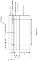
- FIG. 11 shows dimensions of a reactor according to the invention
- FIGS. 12A, 12B and 12C show cross-sectional views of alternative reactor geometries according to the invention.
- FIGS. 13A and 13B show example reaction cell covers that can be used with the invention.
- FIGS. 14A and 14B show a plan view of a reaction cell cover employed in an embodiment of the invention
- FIG. 15 shows an exploded view of a reactor according to the invention
- FIGS. 16A and 16B show two formats of reaction cell employed in the invention
- FIG. 17 shows a simulation of simultaneous DNA amplification and diffusion up to time 60 s followed by DNA diffusion only after time 60 s during operation of the invention
- FIGS. 18A and 18B show the DNA concentration at time 100 s after the start of PCR amplification for two example cells employed with the invention
- FIG. 19 shows the concentration variation in a method employing the invention with position at time 100 s after the start of PCR amplification
- FIGS. 20A and 20B show two different designs of fluidic cell arrays that may be employed with the invention.
- FIG. 21 shows detail of fluidic cell with reaction zones separated by diffusion restrictions
- FIGS. 22A and 22B show detail of outlets of reaction cells with recombining fluidic paths
- FIGS. 23A, 23B and 23C show reaction volumes according to the invention
- FIGS. 24A and 24B show reaction volumes according to the invention
- FIG. 25 shows an electrically conductive heater element according to the invention
- FIG. 26 shows an alternative approach to edge effect compensation in a heater element employed in an embodiment of the invention
- FIG. 27 shows a heater element employed in an embodiment of the invention
- FIGS. 28A, 28B and 28C show the design of a heater for two reaction volumes employed in an embodiment of the invention
- FIGS. 29A, 29B, 29C and 29D show a heater employed in an embodiment of the invention with patterned electrodes
- FIG. 30 shows heater element employed in an embodiment of the invention using combination of low resistance interdigitated electrodes and high resistance areas for heating and temperature sensing;
- FIG. 31 shows a heat sink that can be employed with the invention
- FIGS. 32A and 32B show variation of temperature with time for a heater connected to a heat sink via a thermal resistance
- FIG. 33 shows the variation of heater power and thermal resistance for thermal cycling times in an example reactor according to the invention
- FIG. 34 shows the temperature variation over time for a heater employed in an embodiment of the invention
- FIGS. 35A and 35B show a DNA melt curve data obtained using the reactor of an embodiment of the invention.
- FIG. 36 shows a DNA amplification curve data for thermocycled PCR amplification using the reactor of an embodiment of the invention
- FIGS. 37A and 37B show the temperature differences between a sample and reference cell used to carry out calorimetric detection of DNA melting in an embodiment of the invention
- FIG. 38 shows the temperature profile of a PCR amplification scheme in a method employing the invention.
- FIGS. 39, 40 and 41 show circuits according to the invention.
- FIG. 1A-B shows thermal cycling by moving a sample between water baths held at different temperatures.
- the apparatus is shown in schematic form (A).
- the sample temperature and position are plotted against time in (B).
- FIG. 2 shows thermal cycling by moving a sample between heater blocks held at different temperatures.
- FIG. 3 shows thermal cycling by passing a sample through a serpentine path that passes alternately over higher and lower temperature zones.
- FIG. 4 shows digital PCR by creating droplets of the sample contained in an immiscible liquid, usually a fluorinated oil.
- an immiscible liquid usually a fluorinated oil.
- FIG. 5 shows a top view and a side view of a slip chip device.
- the slip chip uses relative motion of two parts to create isolated sub-samples for digital or multiplexed PCR.
- FIG. 6A-D shows digitisation for digital PCR by filling first with the sample liquid and then with a gas which can pass through a gas-permeable barrier and which divides the sample into disconnected volumes.
- FIG. 7 shows two repeat DSC scans of a 0.0244 mM PNA(TG)/DNA duplex solution, a 0.0303 mM DNA(TG)/DNA duplex solution, and the buffer solution.
- the temperature scan rate was 60K/h and the cell volume was 0.511 ml.
- thermal cycling requires the thermal diffusion time between the heater and sample to be small compared with the target cycle time.
- Table 1 below shows an example reactor design, which will be described below, in which the thermal diffusion times of the reaction volume and thin outer wall are both less than the reaction time for PCR which we take as approximately 1 s for a 100 base pair sequence.
- the heat capacity of the reaction volume should be a large fraction of the sum of the reaction cell and heater heat capacities, preferably >10% and more preferably >50%.
- the heater element In order to heat the reaction volume, the heater element is switched on and heat generated by the heater element flows into the reaction volume and into the heat sink. In order to cool the reaction volume, the heater element is switched off and heat flows from the reaction volume through the heater and into the heat sink.
- the heat capacity of the heat sink is chosen to be much larger than the combined heat capacity of the reaction cell and heater, in order to limit the heat sink temperature rise over the series of thermal cycles needed to complete a reaction. In the example given below, the heat sink heat capacity is >100 times that of the combined heat capacity of the heater and reaction cell.
- the heat sink can be cooled continuously, for example by natural or forced convection, liquid circulation, spray cooling, or connection to a heat pipe or a Peltier device.
- the thermal resistance of the heater support R T can be optimised to minimise the thermal cycling time for a given temperature profile and heatsink temperature T Sink and heater element power p Heat
- axial direction to be perpendicular to the contact surface between the heater and the reaction cell and a lateral direction to be in the plane of the contact surface between the heater and the reaction cell. It is desirable to limit lateral heat flow as lateral heat flow implies temperature gradients and temperature nonuniformity within the reaction cell, reducing the precision of temperature control.
- the reaction volume is chosen to have a ratio of height H V (in the axial direction) to width W V (in the lateral direction) such that the side area is smaller than the area of the face nearest the heater element. This condition is satisfied for a square or circular reaction volume as follows: W V >4 H V .
- the heater element may be designed to have higher heat output near its edges and to extend beyond the reaction volume.
- the higher heat output of the heater element near its edges can compensate for lateral heat flow and provide more uniform temperature conditions across the reaction volume.
- An electrical heater element may have a square or rectangular shaped heat-generating area with electrical terminals on two opposite sides of the heat-generating area and a direction of current flow from one terminal to the other.
- One approach to improving the temperature uniformity of such a heater element is to increase the sheet resistance of the heater element near the sides of the electrical terminals so that the heat output per unit area is increased locally near these sides, relative to the heat output near the centre of the heater element.
- the resistance of the heater element can be increased locally by reducing the thickness of the material or by patterning the material with holes or slots or material variation which has the effect of increasing the length of the electrical conduction path and reducing the cross-section area of the electrical conduction path.
- These hole or slot features must be small compared with the thickness of the reaction volume so that they do not disturb the temperature uniformity within the reaction volume.
- Guard heaters can be used to further limit lateral heat flow at the edges of the heater.
- Guard heaters are additional heaters located near the edge of a heater element and driven to maintain a temperature close to the target temperature of the main heater element.
- the heat output per unit are of the guard heater is higher than that of the main heater element, to compensate for lateral heat loss.
- the guard heater may be operated with closed loop control with the same temperature setpoint as the main heater element or the guard heater may be operated with the same controller or on/off timing as the main heater element but with a different drive voltage which can be adjusted to optimise the temperature uniformity at a specific temperature setpoint.
- the reactor can be configured as a single-sided cell or a double-sided cell.
- the single-side configuration has a reaction cell with one thin outer wall in contact with a heater which is in turn in contact with a heat sink.
- the double-sided configuration has a reaction cell with two thin outer walls in contact with heaters which are in turn in contact with heat sinks.
- the reaction cell, heater and heat sink can have planar or curved forms.
- a planar form may be preferred for ease of construction and optical monitoring of the reaction.
- other forms such as part-spherical or cylindrical are possible and these may have benefits in allowing tensioned flexible reaction cell and heater layers to make good thermal contact with each other and with the heat sink which is typically a rigid metal part.
- the heater element may be configured as a temperature sensor where the resistance of the heater element is used to determine its temperature.
- the heater element may have a positive temperature coefficient of resistance (such as a metal) or a negative temperature coefficient of resistance (such as a metal oxide or other dielectric). In either case it is desirable that the magnitude of the temperature coefficient of resistance (TCR) of the heater element is large, preferably greater than 500 ppm/K, more preferably greater than 2,500 ppm/K and most preferably greater than 10,000 ppm/K.
- the heater element may be provided with four-terminal Kelvin contacts to allow more precise measurement of the resistance of the heater element and more precise temperature measurement.
- the heater element material may be patterned with slots or gaps perpendicular to the direction of current flow to increase the sheet resistance.
- the heater element may be provided with interdigitated contact terminals to decrease the path length through the heater element and to increase the cross-sectional area for current flow.
- PCR amplification of DNA can be detected using fluorescently labelled dyes, or electrochemically active labels.
- fluorescently labelled dyes or electrochemically active labels.
- This invention provides calorimetric detection of amplified DNA by detecting the heat of melting during the heating phase of the thermal cycle, which leads to an increased heat capacity at the melting temperature. This allows PCR amplification to be monitored continuously in a label-free manner with minimal additional instrumentation hardware.
- the format of the reactor of the current invention is well suited to scanning calorimetric detection because the design allows rapid temperature ramp rates and because the heat capacity of the sample contained in the reaction volume is a significant fraction of the total heat capacity of the heater, reaction cell and sample. These factors increase the strength of the calorimetric signal and improve the sensitivity of calorimetric detection.
- a differential thermal analysis (DTA) method can be used, in which the temperature difference between a sample and reference cell is measured as a function of temperature or time while the temperature is ramped through the melting point, with equal heat input to both sample and reference.
- the evolution of the differential temperature scan over the course of the reaction can be monitored to detect a change in the concentration of reaction products.
- DSC differential scanning calorimetry
- AC calorimetry can be combined with the current invention, using a pulsed or oscillating heater drive to increase the robustness and sensitivity of a calorimetric measurement.
- One example approach is to drive a resistive heater with a sinusoidal drive voltage at a drive frequency, generating oscillatory heat output at twice the drive frequency.
- the temperature of the heater element will also oscillate at twice the drive frequency, and the amplitude of this oscillation will depend on the heat capacity of the sample.
- the amplitude of temperature oscillation can be detected by measuring oscillations in the electrical resistance of the heater element when the heater is also configured to be a temperature sensor with non-zero temperature coefficient of resistance.
- the advantage of this approach is that the method is insensitive to slow DC drifts in heater resistance and synchronous detection of the temperature oscillation can be used to reject sources of external noise.
- the optimum range of frequencies of heat input for AC calorimetry can be estimated by considering the penetration depth L of temperature oscillations produced by an oscillating heat source (reference: Marin, E. (2010) Characteristic dimensions for heat transfer Lat. Am. J. Phys. Educ., 1, 56-60).
- L 2 ⁇ D T ⁇ D T is the thermal diffusivity of the material into which the heat diffuses and ⁇ is the angular frequency of the heat source oscillation. It is preferable to choose conditions to give a penetration depth L equal to or smaller than the height of the reaction volume, H V , for the case of a reactor with heater on one side only.
- a benefit of using a higher frequency oscillation and smaller penetration depth is that the calorimetric measurement is less sensitive to variations in H V and this reduces the sensitivity to differences between sample and reference reaction volume geometries.
- condition L ⁇ H V occurs for a sinusoidal electrical drive at frequency f DRIVE applied to a resistive heater element to generate an oscillating heat output at frequency 2 f DRIVE , where f DRIVE satisfies the condition:
- f DRIVE satisfies the condition:
- the penetration depth L be greater than or equal to the thickness H W of the thin outer wall in contact with the reaction volume. This gives the condition:
- a “volume” may also connote a “vessel” or “cell”, which define a volume, and vice versa.
- the sample and reference are each heated with two heater elements and the four heater elements are configured in a full bridge arrangement so that the voltage output of the bridge circuit is doubled for a given temperature difference.
- Digital PCR is a technique in which a sample including PCR reagents is first partitioned into sub-samples in a number of separate compartments (for example droplets or regions partitioned by walls), and all sub-samples are then temperature cycled to allow progression of the PCR reaction.
- the objective is to determine the concentration(s) of one or more target oligonucleotides in the original sample more precisely and more accurately than is possible with real-time PCR.
- Real-time PCR quantifies DNA concentration by determining CT, the number of amplification cycles required for a measurement of the PCR reaction to exceed a threshold value.
- the starting concentration of DNA is related to CT. with higher concentrations resulting in a smaller value of CT.
- Statistical analysis of the number of sub-samples in which PCR successfully progresses allows a more accurate and precise estimate of the DNA concentration in a sample. Sub-samples where PCR progresses must have contained one or more target oligonucleotides, whereas sub-samples where PCR does not progress are assumed to contain none.
- the statistical method requires a large number of sub-samples for precise determination of concentration, and typically more than 1000 sub-samples are used, and more than 10,000 sub-samples for applications requiring higher sensitivity.
- a significant disadvantage of existing digital PCR techniques lies in the requirement to first partition the sample into sub-samples. This requirement adds significantly to the complexity and hardware costs associated with the process.
- Droplet digital PCR requires microfluidic droplet generation with more complex reaction cells, precisely controlled flows of aqueous sample and immiscible oil, and additional time for generation of droplets prior to PCR amplification.
- An alternative to droplet digital PCR is to use a gas to divide reaction volumes. This requires controlled sample addition followed by controlled gas addition combined with use of gas-permeable barriers to allow gas to escape.
- This invention provides a wall-free, droplet-free digital PCR system and method where the sample is not partitioned into disconnected sub-samples. Instead, PCR proceeds (or fails to proceed) in a number of reaction zones within the sample, where these reaction zones are defined only by the range of temperatures they experience. There are no physical barriers between reaction zones, and movement of oligonucleotides from one reaction zone to another is prevented only by the relatively slow diffusion of oligonucleotides through the solution.
- the sample is contained as a continuous body of liquid without solid, immiscible liquid, or gas barriers between sub-samples. This is enabled by the possibility of performing PCR with short cycle times, so that between 30 and 50 cycles of PCR amplification can be completed in less than 100-200 seconds, limiting the time for diffusion and the distance over which diffusion can occur.
- partial barriers may be introduced to define sub-sample locations for ease of subsequent reaction detection and analysis, and to reduce the speed of diffusion between adjacent sub-sample locations, thereby allowing the sub-samples to be more closely spaced and increasing the number of sub-samples for a given size of reactor and total volume of sample.
- the flat reaction volume shape of the reactor described in this invention is convenient for fluorescence detection of amplified DNA for digital PCR using an array detector such as a digital camera.
- Multiplexed PCR is a technique in which a sample is analysed to detect the presence of multiple different oligonucleotide sequences.
- One conventional approach is to use fluorescent labels with different fluorescence wavelengths to multiplex detection of different species, but this approach is typically limited to detection of up to approximately six species, due to the overlap of fluorescence wavelengths.
- An alternative conventional approach is to sub-divide the sample into different reaction volumes partitioned by barriers which can be solid, immiscible liquid or gas. This approach has the same disadvantages of increased complexity and analysis time as for digital PCR described above.
- FIG. 8 shows a single sided reactor A (left) and a double sided reactor B (right) according to the invention.
- Each reactor comprises a reaction cell with one or more heaters and heat sinks.
- the heater comprises a heat-generating heater element on a heater support in contact with a heat sink.
- the heater support may include a softer and more flexible thermal pad layer to provide good thermal contact between a harder and more rigid heater support layer and a harder and more rigid heat sink.
- Embodiment A a reactor with single-sided heater, comprises a single heater and heat sink and a reactor comprising a side wall, thin outer wall and cover. In Embodiment A the reaction volumes are enclosed by the cover, side wall and thin outer wall.
- Embodiment B a reactor with double-sided heater comprises a reaction cell with two thin outer walls surrounding a side wall. In Embodiment B the reaction volumes are enclosed by the side wall and thin outer walls.
- FIG. 9 shows a side view of a single sided reactor A (left) and a double sided reactor B (right) according to the invention.
- FIG. 10 shows a side view of a single sided reactor A (left) and a double sided reactor B (right) without thermal pads according to the invention.
- FIG. 11 shows dimensions of a reactor according to the invention: reaction cell height H V , thin wall thickness H W , heater support height H H , thermal pad height H P , heatsink height H S and reaction cell width W V .
- FIG. 12 shows cross-sectional views of different reactor geometries. All include a reaction cell in contact with a heater in contact with a heat sink. A planar geometry is shown in (A), a curved geometry in (B) and a cylindrical geometry in (C). In all cases the reaction volume is bounded by two larger area substantially parallel walls, and a smaller area side wall. At least one of the large area walls is a thin outer wall which is in contact with a heater.
- reaction cell can have planar or curved forms.
- one or more reaction volumes to which thermocycling is applied may be constructed in a number of ways.
- FIG. 13 shows a cover for a reaction cell cover employed in an embodiment of the invention comprising a substantially flat part with through-holes forming fluidic ports and recessed features defining reaction volumes and fluidic channels connecting the reaction volumes to the fluidic ports.
- the cover is shown in full (A) and in cross-section (B).
- FIG. 14 shows a plan view of a reaction cell cover employed in an embodiment of the invention comprising reaction volumes connected by fluidic channels to fluidic ports.
- the reaction volumes may have an elongated or rectangular shape (A) or a substantially square shape (B).
- FIG. 15 shows an exploded view of a reactor according to the invention, which comprises the assembly of a reaction cell, heater and heat sink.
- the reaction cell contains two reaction volumes, with each reaction volume located above a heater element which extends laterally beyond the edge of the reaction volume.
- the heater makes thermal contact with the heat sink (optionally via a thermal pad, not shown in this figure).
- a thermally insulating air gap located near the perimeter of the heater element region may be used to locally reduce the rate of heat flow from the heater to the heat sink, thereby reducing the tendency for the edges of the heater element regions to be cooler than the centre, and improving the thermal uniformity within the reaction volume.
- FIG. 16 shows two formats of reaction cell employed in embodiments of the invention: (A) reaction cell for multiple samples (8-sample format shown), and (B) reaction cell for a single sample with multiple detection locations.
- the detection locations may be used to implement digital PCR where the number of locations at which amplified DNA is detected is used to calculate the concentration of the target sequence in the sample.
- the detection locations may also be used to implement multiplexed PCR to detect multiple different target sequences, for example by providing different sequence-specific PCR primers at different detection locations.
- the reaction cell in each of FIGS. 16(A) and 16(B) may have a single reaction volume associated with a single heater element.
- different primer pairs can be pre-loaded at different locations within the reaction volume, for example by deposition of an array of primer pairs onto an array of locations on one of the large area walls of the reaction cell, followed by drying.
- Primer-specific amplification can occur at the location of each primer-pair and the result of this amplification can be determined independently of the outcome of PCR amplification at neighbouring locations, provided that the PCR amplification is carried out in less time than the time required for reaction products or primers to diffuse to neighbouring locations.
- a typical primer is an oligonucleotide sequence with approximately 20 bases and is shorter than the target DNA sequence, with correspondingly larger diffusion coefficient. Applying the same formula as for DNA diffusion, a 20 base primer may diffuse 151 ⁇ m within a time of 100 s.
- Independent detection requires that adjacent locations for multiplexed detection must be separated by at least twice this distance, and preferably at least 4 to 6 times this distance. As an example, we can consider a 5 ⁇ l reaction volume with height 100 ⁇ m, area 50 mm2, and approximately 1 mm spacing between adjacent locations. Each detection location occupies an area of 1 mm2, giving 50 independent detection locations for multiplexing.
- FIG. 17 shows a simulation of simultaneous DNA amplification and diffusion up to time 60 s followed by DNA diffusion only after time 60 s in a reactor according to the invention.
- a centre cell contains one DNA molecule and this is amplified by PCR with a cycle time of 2 s.
- the case of a reaction cell with diffusion restriction channels is shown with a solid line, while the case of a reaction cell without diffusion restriction channels is shown with a dashed line.
- Fast amplification is required in to amplify fully in one reaction zone before significant diffusion and amplification in a neighbouring zone can occur.
- the DNA concentration in the neighbouring cell with diffusion restriction channel is approximately 5% of the DNA concentration in the main cell at time 60 s, while the DNA concentration in the neighbouring cell is approximately 35% in the case without diffusion restriction channels.
- FIGS. 18A and 18B shows the results of a simulation of DNA concentration in a method employing the invention at time 100 s for two cases: FIG. 18A is a reaction cell without diffusion restriction channels, while FIG. 18B is a reaction cell with separate reaction zones (detection locations) separated by diffusion restriction channels. DNA diffusion to neighbouring cells is reduced by the diffusion restriction channels. In both cases, PCR amplification is simulated for 60 s (30 cycles of PCR amplification with 2 s per cycle), followed by diffusion for a further 40 s.
- the reaction cell in each of FIGS. 18(A) and 18(B) may have a single reaction volume associated with a single heater element.
- FIG. 19 shows the concentration variation in a method employing the invention with position at time 100 s after the start of PCR amplification.
- the diffusion barrier helps to maintain high DNA concentrations near the locations where DNA has been amplified and low concentrations in neighbouring reaction locations. This allows digital PCR or multiplexed PCR or other reactions to be carried out in a reactor with a continuous fluid path for reagent and sample flow, avoiding the need for droplets or other measures to isolate the reacting volumes.
- FIG. 20 shows two different designs of fluidic cell with an array of reaction zones connected by smaller channels which restrict diffusion between adjacent reaction zones according to the invention.
- the reaction zones may contain different reagents such as PCR primers in order to carry out a multiplexed amplification and detection of different DNA sequences at different locations.
- the reaction zones may all contain the same reagents in order to carry out digital PCR.
- the diffusion restriction channels allow the array of reaction zones to be filled without the need for generation of aqueous droplets in oil to provide isolated reaction zones, thus simplifying and reducing the cost of carrying out the reaction.
- the fluidic cell in each of FIGS. 20(A) and 20(B) may have a single reaction volume associated with a single heater element
- FIG. 21 shows detail of a fluidic cell with reaction zones 330 separated by diffusion restrictions 340.
- the fluidic paths from the reaction zones recombine to allow the reaction product to be collected and transferred out of the reaction cell.
- FIG. 22 shows detail of the outlets of reaction cells with recombining fluidic paths.
- a sequence of capillary flow restrictions are placed in the fluidic path, with the capillary burst pressure increasing in the flow direction.
- the larger radius capillary flow restriction 351 has a lower burst pressure than the smaller radius capillary flow restriction 352.
- one channel can pin at a capillary flow restriction until the adjacent channel is filled, at which point the menisci of the two advancing liquid fronts can touch and the flows recombine without generation of air bubbles.
- FIG. 22(B) liquid flow is stopped at the smaller capillary radius flow restriction points 352 while liquid flows past the larger capillary radius flow restriction point 351. Liquid streams recombine as the advancing meniscus reaches each of the restriction points 352.
- FIG. 23 shows another embodiment of a reaction cell in which a reaction volume 220 has width W V , length L V and height H V .
- the reaction volume 220 is located in register with and arranged to be heated by a heater element 500, and is constructed from a serpentine fluidic channel 270 with height H V which distributes a sample across the reaction volume area W V ⁇ L V .
- a reaction cell containing a reaction volume with this form provides several advantages: the fluidic path is easily controlled, bubbles can be flushed out, and the part can be manufactured using an embossing and laminating process to attach a thin outer wall 230 to the fluidic cell.
- PCR primers may be provided as a linear array along the serpentine channel. Primers may be chosen in view of their solubility, such that the primers remain substantially fixed along the channel.
- FIG. 24 shows another embodiment with a serpentine fluidic channel.
- four reaction volumes 220 are arranged to be filled from a single sample via serpentine fluidic channels 270 and thermocycled by a heater element 500.
- Each reaction volume has width W V and length L V .
- FIG. 25 shows an electrically conductive heater element employed in an embodiment of the invention with zones of intermediate, low and high sheet resistance to provide increased heating near the edges of the heater element, in order to increase the uniformity of the temperature across the element.
- the heater element is formed from a thin film conductor supported on an electrically insulating support.
- the sheet resistance of the heater element is locally increased by forming holes in the electrically conductive thin film, with a larger hole area fraction causing a larger increase in sheet resistance.
- An electric current flows between the electrical terminals to provide higher heating power density due to increased sheet resistance in the upper and lower high resistance zones and higher heating power density due to increased current density in the left and right lower resistance zones.
- the heater is also made partially transparent by forming holes in the electrically conductive layer, which is typically opaque. A partially transparent heater element is useful to allow optical monitoring of the reaction and in particular fluorescence detection of amplified DNA.
- FIG. 26 shows an alternative approach to edge effect compensation in a heater element employed in an embodiment of the invention.
- Guard heaters are provided at one or more edges of the main heater, and the guard heaters are driven electrically to the same temperature setpoint as the guard heater.
- the main heater also has end heater zones with higher electrical resistance to provide increased heating near the ends, thereby reducing edge effects.
- the main heater is provided with four-terminal Kelvin connections so that its resistance can be measured accurately and used to calculate the temperature of the heater element. The resulting temperature measurement is used to control the heater drive power and thermocycling behaviour.
- FIG. 27 shows a heater element employed in an embodiment of the invention comprising a main heater with guard heaters located near two of the edges.
- the main heater is elongated and the guard heaters are located near the long edges.
- the main heater has a lower resistance central zone and higher resistance end zones, such that a current flowing in the long direction of the heater will cause increased heat output in the high resistance end zones and this increased heat output will compensate for edge effects, increasing the temperature uniformity of the heater.
- a benefit of an elongated heater element is that it matches the form of an elongated reaction volume which is convenient to manufacture and convenient to fill without trapping air bubbles. The perforations in the main heater make the heater partially transparent.
- FIG. 28A shows the design of a heater for two reaction volumes employed in an embodiment of the invention.
- the heater contains two elongated main heater elements with three guard heater elements adjacent to the long edges of the main heater element.
- the end zones of the main heaters have a higher sheet resistance created by increasing the area fraction of holes in a thin film conductor ( FIG. 28C ), while the central zones of the main heaters have a lower sheet resistance created by decreasing the area fraction of holes in a thin film conductor ( FIG. 28B ).
- the main heaters are provided with Kelvin contacts to allow the heater resistance to be measured accurately. The change in heater resistance with temperature is used to monitor and control the heater temperature. Separate electrical contacts are provided for the guard heaters, allowing independent electrical drive and control.
- the outer guard heaters may be designed to have a lower resistance than the inner guard heater so that when all the guard heaters are driven with the same voltage, the outer guard heaters generate more heat which improves the temperature uniformity as greater heat output compensates for the greater heat loss at the edge of the heater.
- FIG. 29 shows a heater employed in an embodiment of the invention with patterned electrodes to vary resistance.
- the heater (A) has two main heaters which have higher resistance regions near their short ends and lower resistance regions in the centre. The resistance can be adjusted by the geometry of gap regions which provide variable conductor geometry.
- (B) shows an example of a higher and lower resistance region.
- the elongated gap is oriented perpendicular to the direction of current flow in order to increase the sheet resistance of the heater element.
- the larger aspect ratio gap provides a higher resistance end zone, while the smaller aspect ratio gap provides a lower resistance centre zone.
- the design of the main heater is robust to a single track breaking, by providing parallel electrical conduction paths.
- Guard heaters are placed near the long sides of the main heaters.
- the outer guard heaters (C) have lower resistance than the inner guard heater (D) in order to provide greater heat output when driven with the same drive voltage.
- the heater element is substantially continuous with any holes having diameter less than the thickness of the reaction volume, H V , or in the case of elongated gaps in the heating element, the gap width less than the thickness of the reaction volume, H V .
- FIG. 30 shows a heater element employed in an embodiment of the invention using a combination of low resistance interdigitated electrodes and high resistance areas for heating and temperature sensing.
- the high resistance areas could be fabricated using a metal oxide material such as Vanadium Oxide with a large temperature coefficient of resistance (TCR) in the temperature range of interest, and the low resistance interdigitated electrodes could be fabricated using a thin film of a metal such as gold, aluminium or copper with lower sheet resistance than the high resistance heating and sensing areas.
- TCR temperature coefficient of resistance
- FIG. 31 shows a heat sink employed in an embodiment of the invention perforated with holes to allow optical monitoring of a reaction, when used in combination with a partially transparent heater element.
- the diameter and pitch of the holes are chosen to be small enough not to disturb the temperature uniformity of the reaction cell.
- a typical example uses holes with dimeter 1 mm on a 2 mm pitch in an aluminium heat sink block with a thickness of 2 mm. This arrangement allows optical monitoring of a reaction even in the case where the reactor has heaters and heat sinks on both sides.
- FIG. 32 shows variation of temperature with time for a heater connected to a heat sink via a thermal resistance (A) in accordance with the invention.
- the thermal resistance which minimises the thermal cycling time
- the optimum thermal resistance is approximately 10K/W.
- a higher power heater requires a lower thermal resistance for minimised thermal cycling time, and a lower power heater requires a higher thermal resistance for minimised thermal cycling time.
- a 5W heater requires 20K/W thermal resistance
- a 20W heater requires 5K/W.
- FIG. 33 shows the variation of heater power and thermal resistance for thermal cycling times of 0.4 s, 0.8 s and 1.6 s in an example reactor according to the invention. For a fixed thermal cycling time, there is an optimum thermal resistance which minimises the heater power required.
- FIG. 34 shows the temperature variation over time for a heater employed in an embodiment of the invention driven between 90° C. and 60° C.
- the thermal cycling time is 2 s.
- the solid line shows the temperature setpoint and the dotted lines show temperature measurements.
- FIG. 35 shows a DNA melt curve data obtained using the reactor of an embodiment of the invention.
- the presence of double-stranded DNA is indicated using an intercalating dye SYBR-GREEN which shows a sudden reduction in fluorescence as the temperature rises above the melting temperature of the DNA, in this case around 83° C.
- SYBR-GREEN shows a sudden reduction in fluorescence as the temperature rises above the melting temperature of the DNA, in this case around 83° C.
- the variation of fluorescence with temperature is shown in A and the gradient—dF/dT is shown in B.
- FIG. 36 shows a DNA amplification curve data for thermocycled PCR amplification using the reactor of an embodiment of the invention.
- the upper graph shows fluorescence of an intercalating dye against time, showing growth of DNA concentration above the background level at approximately 120 s.
- the lower graph shows temperature against time.
- An initial hot-start is used to activate the polymerase enzyme, following which a 5 s thermocycling time is used with high and low temperatures of 95° C. and 60° C.
- FIG. 37 shows the temperature difference between a sample and a reference cell used to carry out calorimetric detection of DNA melting in an embodiment of the invention.
- the sample cell contains a DNA concentration of 1 ⁇ M and the reference cell contains no DNA.
- the increase in heat capacity due to the DNA melting causes a depression in the temperature when the sample and reference cells are driven with equal power.
- a direct current drive is shown in A while an alternating current drive is shown in B.
- the alternating current drive gives an temperature oscillation at twice the drive frequency when the DNA is undergoing the melting transition. Electrical detection of the signal generated by the alternating current drive may be easier to detect than the direct current drive.
- the frequency of the alternating current drive is chosen to give a heating period approximately equal to the time for thermal diffusion through the height of the reactor. The heating period is equal to 1 ⁇ 4 of the cycle time of a sinusoidal drive.
- FIG. 38 shows the temperature profile of a PCR amplification scheme in a method employing the invention with a 20 s hot start period followed by a 5 s thermal cycle repeated 30 times.
- Differential scanning calorimetry is used to detect the amplified DNA as follows: a baseline differential temperature scan (recording the temperature difference between sample and reference cells against temperature) is measured during the temperature ramp of the hot start period. An endpoint temperature scan is made during the temperature ramp of the last PCR cycle. The difference between the baseline and endpoint scans is proportional to the heat of melting of the DNA.
- FIG. 39 shows a bridge circuit according to the invention for calorimetric detection of DNA melting.
- a sample cell is heated by resistors R 1 and R 4 , while a reference cell is heated by resistors R 2 and R 3 .
- the sample cell will have a lower temperature and the resistance values of R 1 and R 4 will be reduced, generating a higher voltage at the positive (non-inverting) input of amplifier X 1 and a lower voltage at the negative (inverting) input of the amplifier X 1 .
- a direct current drive V 1 is shown, but an alternating current drive could also be used.
- a frequency selective detection scheme can be used to detect signals only at twice the drive frequency.
- frequency-selective detection can be used detect signals at the same frequency as the drive frequency. It is desirable for the heater resistors to have a large temperature coefficient of resistance in order to generate a measurable signal voltage from a small temperature difference.
- thermocouples connected between the sample and reference cells generate a signal voltage proportional to the temperature difference between the cells.
- FIG. 40 shows a balancing circuit according to the invention using additional series resistors R 5 , R 6 , R 7 , and R 8 to minimise the differential voltage output of the bridge circuit and to minimise the differences in power output of the sample heater comprising R 1 and R 4 and the reference heater comprising R 2 and R 3 .
- the values of R 5 , R 6 , R 7 and R 8 can be set on manufacture or can be adjusted before detection. It is desirable to minimise the bridge circuit voltage imbalance to enable high amplification gain and sensitive detection without saturating X 1 . Equal power input to the sample and reference cells is desirable to ensure that both cells reach the DNA melting temperature at the same time, giving a signal proportional to the difference in DNA concentration between the two cells.
- FIG. 41 shows additional parallel resistors R 5 , R 6 , R 7 , and R 8 that may be employed with the invention to minimise the differential voltage output of the bridge circuit and to minimise the differences in power output of the sample heater and the reference heater.
- a variable-temperature reactor for hosting a predetermined reaction therein, the reactor comprising a reaction cell, a heater, and a heat sink,
- reaction cell has a reaction volume with thickness H V and width W V where W V >4 H V and is defined by faces with one of the larger area faces of the reaction volume being bounded by an outer wall with thickness H W ;
- the heater comprises a heat-generating heater element located on the face closer to the reaction volume and a heater support on the opposite face, the heater support being in contact with a heat sink, such that the heater support provides a thermal resistance R T between the heater element and the heat sink,
- reaction cell contains a reaction volume with width W V and length L V formed by a serpentine channel located within an area having width W V and length L V .
- reaction cell has an inlet channel and an outlet channel connecting fluid inlet and outlet ports to the reaction volume.
- reaction cell comprises liquid-contact material which is an inert polymer.
- the reactor is arranged to cycle repeatedly between a lower temperature T LOW and a higher temperature T HIGH using a heater with power output p Heat and a heat sink at a temperature T Sink .
- the heater element is fabricated from an electrically conductive material with a positive TCR, and may comprise one of Pt, Ti, Al, Mo, Ni, Cu, Au.
- the resistive heating element is fabricated from a material with a negative TCR, such as a metal oxide which undergoes a transition from being electrically insulating to electrically conducting as temperature rises, such as Vanadium Oxide.
- the heater element comprises a main heater surrounded by one or more guard heaters.
- reaction volume is arranged to contain, in use, reagents used for polymerase chain reaction (PCR) amplification of nucleic acid sequences.
- PCR polymerase chain reaction
- reaction sensors are located within the outer wall of the reaction volume or in are contact with the outer wall of the reaction volume.
- the reactor of any preceding clause configured for calorimetric detection of the result of the reaction by comprising a measurement component for measuring a change in the heat capacity of a sample in the reactor.
- reactor of any preceding clause wherein the reactor is configured for DTA or DSC by being structured to use a sample reaction and a reference reaction.
- reaction product which is DNA or RNA and arranged so that melting of the reaction product is detected calorimetrically.
- reaction volume with height H V and contents with thermal diffusivity D V and thin reaction chamber wall with thickness H W and with thermal diffusivity D W are arranged to be heated by heaters on both sides where the frequency of the heater drive satisfies the relationship:
- reactor of any preceding clause further comprising a resistive heater element which is driven with a sinusoidal waveform at a drive frequency and comprising means for measuring the temperature of the heater element by measuring variations in heater element resistance at a frequency of 2 ⁇ the drive frequency, or by measuring variations in the heater voltage or current at 3 ⁇ the drive frequency.
- the heater element is formed from a transparent conductive material such as ITO or graphene or nanowire materials.
- reaction volume contains a plurality of spatially separated zones with different reagents located in different zones of the reaction volume, and with the zone spacing greater than the greater of the mass diffusion length of the reaction products and mass diffusion length of the reagents on the timescale of the reaction time constant, t R , and different reactions are monitored independently within each reaction zone.
- a heater for a variable temperature reactor comprising a heating element, wherein the heating element functions both as a heater and as a temperature sensor.
- the heater element is fabricated from an electrically conductive material with a positive TCR, and may comprise one of Pt, Ti, Al, Mo, Ni, Cu, Au.
- the resistive heating element is fabricated from a material with a negative TCR, such as a metal oxide which undergoes a transition from being electrically insulating to electrically conducting as temperature rises, such as Vanadium Oxide.
- the heater of clause 86 comprising means to control the temperature of the guard heaters to the same temperature setpoint as the main heater.
- a driving and sensing circuit for a variable temperature reactor comprising means for providing power to a sample resistive heater and a reference resistive heater and means for sensing the temperature difference between a sample and reference by monitoring the sample resistive heater and the reference resistive heater and two fixed resistors arranged in a bridge circuit.
- a driving and sensing circuit for a variable temperature reactor comprising means for providing power to two sample resistive heaters and two reference resistive heaters arranged in a bridge circuit, and means for measuring the temperature difference between a sample and a reference by monitoring the two sample resistive heaters and two reference resistive heaters, where each side of the bridge circuit is arranged such that, in use, it contains one resistive heater from each of a sample and reference vessel.
- circuit of clause 93 or 94 further comprising trim resistors to balance simultaneously the bridge circuit output voltage and the heater power applied to the sample and reference vessels.
Abstract
Description
R T>(T HIGH −T Sink)/p Heat and
0.5R T,Opt <R T<2R T,Opt
where R T,Opt=(T HIGH +T LOW−2T Sink)/p Heat,
t=R 2 /D T,
where R is the characteristic length scale and DT is the thermal diffusivity of the material. Table 1 below shows an example reactor design, which will be described below, in which the thermal diffusion times of the reaction volume and thin outer wall are both less than the reaction time for PCR which we take as approximately 1 s for a 100 base pair sequence.
R T,Opt=(T HIGH +T LOW−2T Sink)/p Heat.
W V>4H V.
| TABLE 1 |
| Example reactor materials, thermal properties and geometry. Single layer and double layer heater examples |
| are given. The thermal properties of the sample contained in the reaction volume are assumed to be the same as for |
| water. |
| Heater | Heater | ||||
| Reaction cell | (double layer) | (single layer) |
| reaction | thin outer | rigid | flexible | flexible | |||
| volume | wall | layer | layer | layer | Heat sink | ||
| material | water | polypropylene | glass | thermal pad | polyimide | aluminium | |
| thermal | W/m/K | 0.6 | 0.15 | 0.8 | 0.5 | 0.12 | 200 | |
| conductivity | ||||||||
| specific heat | J/K/kg | 4182 | 1920 | 753 | 1200 | 1090 | 897 | |
| capacity | ||||||||
| density | kg/m3 | 1000 | 946 | 2700 | 1100 | 1420 | 2700 | |
| thermal diffusivity | m2/s | 1.4E−07 | 8.3E−08 | 3.9E−07 | 3.8E−07 | 7.8E−08 | 8.3E−05 | |
| thermal effusivity | W · s1/2/m2/K | 1584 | 522 | 1275 | 812 | 431 | 22009 | |
| | μl | 5 | 1.2 | 15 | 6.4 | 3.8 | 5000 | |
| | mm | 2 | 50 | 50 | 50 | 50 | 50 | 500 |
| side (if square) | mm | 7.1 | 7.1 | 7.1 | 7.1 | 7.1 | 22.4 | |
| thickness | mm | 0.1 | 0.024 | 0.3 | 0.127 | 0.076 | 10 | |
| thermal diffusion | s | 0.07 | 0.007 | 0.23 | 0.043 | 0.075 | 1.2 | |
| time | ||||||||
| thermal resistance | K/W | 3.3 | 3.2 | 7.5 | 5.1 | 12.7 | 0.10 | |
| heat capacity | J/K | 0.021 | 0.0022 | 0.031 | 0.0084 | 0.0059 | 12.1 | |
DT is the thermal diffusivity of the material into which the heat diffuses and ω is the angular frequency of the heat source oscillation. It is preferable to choose conditions to give a penetration depth L equal to or smaller than the height of the reaction volume, HV, for the case of a reactor with heater on one side only. A benefit of using a higher frequency oscillation and smaller penetration depth is that the calorimetric measurement is less sensitive to variations in HV and this reduces the sensitivity to differences between sample and reference reaction volume geometries.
For a typical reaction volume according to the invention, wall thickness HW=24 μm, thermal diffusivity for a polypropylene wall DW=8.26×10⁻⁸ m2/s, and fDRIVE≤23 Hz. Preferably, as referred to herein, a “volume” may also connote a “vessel” or “cell”, which define a volume, and vice versa.
D DNA=[bp size]−0.72×4.9×10−6 cm2/s.
V P =πR D 2 H V.
R T>(T HIGH −T Sink)/p Heat and
0.5R T,Opt <R T<2R T,Opt
where R T,Opt=(T HIGH +T LOW−2T Sink)/p Heat,
Claims (24)
Priority Applications (2)
| Application Number | Priority Date | Filing Date | Title |
|---|---|---|---|
| US17/324,457 US11338296B2 (en) | 2018-07-26 | 2021-05-19 | Variable temperature reactor, heater and control circuit for the same |
| US17/722,243 US20220280946A1 (en) | 2018-07-26 | 2022-04-15 | Variable Temperature Reactor, Heater, and Control Circuit for the Same |
Applications Claiming Priority (5)
| Application Number | Priority Date | Filing Date | Title |
|---|---|---|---|
| GB1812192.1 | 2018-07-26 | ||
| GBGB1812192.1A GB201812192D0 (en) | 2018-07-26 | 2018-07-26 | Variable temperature reactor, heater and control circuit for the same |
| PCT/GB2019/052100 WO2020021280A1 (en) | 2018-07-26 | 2019-07-26 | Variable temperature reactor, heater and control circuit for the same |
| US202014124001A | 2020-12-16 | 2020-12-16 | |
| US17/324,457 US11338296B2 (en) | 2018-07-26 | 2021-05-19 | Variable temperature reactor, heater and control circuit for the same |
Related Parent Applications (2)
| Application Number | Title | Priority Date | Filing Date |
|---|---|---|---|
| US202014124001A Continuation | 2018-07-26 | 2020-12-16 | |
| US202017124001A Continuation | 2018-07-26 | 2020-12-16 |
Related Child Applications (1)
| Application Number | Title | Priority Date | Filing Date |
|---|---|---|---|
| US17/722,243 Continuation US20220280946A1 (en) | 2018-07-26 | 2022-04-15 | Variable Temperature Reactor, Heater, and Control Circuit for the Same |
Publications (2)
| Publication Number | Publication Date |
|---|---|
| US20210276016A1 US20210276016A1 (en) | 2021-09-09 |
| US11338296B2 true US11338296B2 (en) | 2022-05-24 |
Family
ID=63518305
Family Applications (2)
| Application Number | Title | Priority Date | Filing Date |
|---|---|---|---|
| US17/324,457 Active US11338296B2 (en) | 2018-07-26 | 2021-05-19 | Variable temperature reactor, heater and control circuit for the same |
| US17/722,243 Pending US20220280946A1 (en) | 2018-07-26 | 2022-04-15 | Variable Temperature Reactor, Heater, and Control Circuit for the Same |
Family Applications After (1)
| Application Number | Title | Priority Date | Filing Date |
|---|---|---|---|
| US17/722,243 Pending US20220280946A1 (en) | 2018-07-26 | 2022-04-15 | Variable Temperature Reactor, Heater, and Control Circuit for the Same |
Country Status (8)
| Country | Link |
|---|---|
| US (2) | US11338296B2 (en) |
| EP (1) | EP3826768A1 (en) |
| JP (2) | JP2021531975A (en) |
| CN (2) | CN115739212A (en) |
| AU (1) | AU2019311817B2 (en) |
| CA (1) | CA3107598A1 (en) |
| GB (1) | GB201812192D0 (en) |
| WO (1) | WO2020021280A1 (en) |
Citations (126)
| Publication number | Priority date | Publication date | Assignee | Title |
|---|---|---|---|---|
| EP0436644A1 (en) | 1988-09-30 | 1991-07-17 | New York Health Res Inst | Nucleic acid probes containing improved molecular switch, and assays and kits incorporating same. |
| US5210015A (en) | 1990-08-06 | 1993-05-11 | Hoffman-La Roche Inc. | Homogeneous assay system using the nuclease activity of a nucleic acid polymerase |
| WO1994008032A1 (en) | 1992-09-29 | 1994-04-14 | Cedars-Sinai Medical Center | One step rna and combined one step rna and dna polymerase chain reaction for detection of rare rna or rna and dna |
| WO1996015270A1 (en) | 1994-11-16 | 1996-05-23 | Perkin-Elmer Corporation | Self-quenching fluorescence probe and method |
| US5561058A (en) | 1986-08-22 | 1996-10-01 | Hoffmann-La Roche Inc. | Methods for coupled high temperatures reverse transcription and polymerase chain reactions |
| WO1997011085A1 (en) | 1995-09-19 | 1997-03-27 | University Of Massachusetts | Inhibited biological degradation of oligodeoxynucleotides |
| EP0506889B1 (en) | 1989-12-22 | 1997-04-02 | F. Hoffmann-La Roche AG | High temperature reverse transcriptases |
| US5624833A (en) | 1986-08-22 | 1997-04-29 | Hoffmann-La Roche Inc. | Purified thermostable nucleic acid polymerase enzyme from Thermotoga maritima |
| US5674738A (en) | 1986-08-22 | 1997-10-07 | Roche Molecular Systems, Inc. | DNA encoding thermostable nucleic acid polymerase enzyme from thermus species Z05 |
| WO1997046707A2 (en) | 1996-06-04 | 1997-12-11 | University Of Utah Research Foundation | System and method for monitoring for dna amplification by fluorescence |
| AU3481297A (en) | 1996-06-04 | 1998-01-05 | University Of Utah Research Foundation | Monitoring hybridization during pcr |
| WO1998004746A1 (en) | 1996-07-31 | 1998-02-05 | Mount Sinai School Of Medicine Of The City University Of New York | Nucleic acid amplification method: ramification-extension amplification method (ram) |
| US6020130A (en) | 1995-06-07 | 2000-02-01 | Nexstar Pharmaceuticals, Inc. | Nucleic acid ligands that bind to and inhibit DNA polymerases |
| WO2000009651A1 (en) | 1998-08-12 | 2000-02-24 | University Of Utah Research Foundation | Dna amplification using electrolyte conductance heating and temperature monitoring |
| WO2000018965A1 (en) | 1998-09-30 | 2000-04-06 | University Of Utah Research Foundation | Multiplex genotyping using fluorescent hybridization probes |
| AU2233400A (en) | 1996-06-04 | 2000-06-01 | University Of Utah Research Foundation | Fluorescent donor-acceptor pair |
| EP1059523A2 (en) | 1999-04-27 | 2000-12-13 | University of Utah Research Foundation | Automated real-time analysis of nucleic acid amplification |
| WO2001012854A2 (en) | 1999-08-13 | 2001-02-22 | University Of Utah Research Foundation | Color compensation for temperature and electronic gains |
| AU3516501A (en) | 2000-04-18 | 2001-10-25 | F. Hoffmann-La Roche Ag | High temperature reverse transcription using mutant DNA polymerases |
| WO2002014555A2 (en) | 2000-08-11 | 2002-02-21 | University Of Utah Research Foundation | Single-labeled oligonucleotide probes |
| US20020022261A1 (en) | 1995-06-29 | 2002-02-21 | Anderson Rolfe C. | Miniaturized genetic analysis systems and methods |
| US20020028452A1 (en) | 1999-03-30 | 2002-03-07 | Wittwer Carl T. | Method for quantification of an analyte |
| WO2002044339A2 (en) | 2000-12-01 | 2002-06-06 | Zhang David Y | Nucleic acid amplification methods |
| US20020119465A1 (en) | 1999-10-01 | 2002-08-29 | Ningyue Zhao | Novel one step RT-PCR methods, enzyme mixes and kits for use in practicing the same |
| WO2002070751A1 (en) | 2001-03-02 | 2002-09-12 | University Of Pittsburgh Of The Commonwealth System Of Higher Education | Pcr method |
| US20020142300A1 (en) | 2000-01-25 | 2002-10-03 | Bernard Philip S. | Simultaneous screening and identification of sequence alterations from amplified target |
| US20020168671A1 (en) | 1996-11-20 | 2002-11-14 | The Regents Of The University Of Michigan | Chip-based isothermal amplification devices and methods |
| US20030008286A1 (en) | 2001-07-05 | 2003-01-09 | Institute Of Microelectronics | Miniaturized multi-chamber thermal cycler for independent thermal multiplexing |
| WO2003004991A2 (en) | 2001-07-03 | 2003-01-16 | Impath, Inc. | Method for detection, quantitation and breakpoint cluster region determination of fusion transcripts |
| WO2003006161A2 (en) | 2001-07-11 | 2003-01-23 | Dongqing Li | Microchannel thermal reactor |
| WO2003033722A2 (en) | 2001-10-15 | 2003-04-24 | Mount Sinai School Of Medicine Of New York University | Nucleic acid amplification methods |
| US20030165867A1 (en) | 2002-02-12 | 2003-09-04 | Eyre David J. | Multi-test analysis of real-time nucleic acid amplification |
| WO2003091408A2 (en) | 2002-04-26 | 2003-11-06 | University Of Utah Research Foundation | Characterization of single stranded nucleic acids by melting analysis using a double strand specific nucleic acid dye |
| EP1362928A2 (en) | 2002-05-13 | 2003-11-19 | The University of Utah Research Foundation | Genotyping by amplicon melting curve analysis |
| WO2004038038A2 (en) | 2002-10-23 | 2004-05-06 | University Of Utah Research Foundation | Amplicon melting analysis with saturation dyes |
| US20040096964A1 (en) | 2000-02-11 | 2004-05-20 | Stmicroelectronics S.R.1. | Integrated device for amplification and other biological tests, and manufacturing process thereof |
| WO2004065629A1 (en) | 2003-01-17 | 2004-08-05 | The Chinese University Of Hong Kong | Circulating mrna as diagnostic markers for pregnancy-related disorders |
| US20040206749A1 (en) | 2001-04-23 | 2004-10-21 | Flavio Villa | Integrated device based upon semiconductor technology, in particular chemical microreactor |
| US20040214315A1 (en) * | 1998-10-29 | 2004-10-28 | Analytik Jena Ag | Ultrathin-walled multi-well plate for heat block thermocycling |
| US20040227529A1 (en) | 2001-11-13 | 2004-11-18 | Caliper Life Sciences, Inc. | Method and apparatus for controllably effecting samples using two signals |
| US20050002835A1 (en) | 2001-11-01 | 2005-01-06 | Astrazeneca Ab | Micro-engineered reactor |
| US20050009101A1 (en) | 2001-05-17 | 2005-01-13 | Motorola, Inc. | Microfluidic devices comprising biochannels |
| US20050006372A1 (en) | 2003-07-10 | 2005-01-13 | Citizen Watch Co., Ltd | Temperature regulator for microchemical chip |
| US20050019902A1 (en) | 1995-09-28 | 2005-01-27 | Mathies Richard A. | Miniaturized integrated nucleic acid processing and analysis device and method |
| WO2006034215A2 (en) | 2004-09-20 | 2006-03-30 | University Of Pittsburgh - Of The Commonwealth System Of Higher Education | Multiple mode multiplex reaction quenching method |
| US20060110763A1 (en) | 2004-11-20 | 2006-05-25 | Roche Molecular Systems, Inc. | Nucleic acid preparation |
| WO2006089192A2 (en) | 2005-02-18 | 2006-08-24 | Canon U.S. Life Sciences, Inc. | Devices and methods for identifying genomic dna of organisms |
| US20060191887A1 (en) | 2003-01-27 | 2006-08-31 | Baer Thomas M | Apparatus and method for heating microfluidic volumes and moving fluids |
| WO2006121423A2 (en) | 2004-04-20 | 2006-11-16 | University Of Utah Research Foundation | Nucleic acid melting analysis with saturation dyes |
| WO2007035806A2 (en) | 2005-09-20 | 2007-03-29 | University Of Utah Research Foundation | Melting curve analysis with exponential background subtraction |
| WO2007092643A2 (en) | 2006-02-09 | 2007-08-16 | Caliper Life Sciences, Inc. | Method and apparatus for generating thermal melting curves in a microfluidic device |
| WO2008005241A2 (en) | 2006-06-30 | 2008-01-10 | Canon U.S. Life Sciences, Inc. | Systems and methods for monitoring the amplification and dissociation behavior of dna molecules |
| WO2008005321A2 (en) | 2006-06-30 | 2008-01-10 | Canon U.S. Life Sciences, Inc. | Systems and methods for real-time pcr |
| EP1897612A1 (en) | 2006-09-05 | 2008-03-12 | Danmarks Tekniske Universitet | A microreactor |
| WO2008061129A2 (en) | 2006-11-14 | 2008-05-22 | University Of Utah Research Foundation | Methods and compositions related to continuous flow thermal gradient pcr |
| WO2008066869A2 (en) | 2006-11-30 | 2008-06-05 | Canon U.S. Life Sciences, Inc. | Systems and methods for monitoring the amplification and dissociation behavior of dna molecules |
| EP1978109A1 (en) | 2007-04-05 | 2008-10-08 | Roche Diagnostics GmbH | Rapid one-step RT-PCR |
| WO2009032087A1 (en) | 2007-08-29 | 2009-03-12 | Canon U.S. Life Sciences, Inc. | Microfluidic devices with integrated resistive heater electrodes |
| US20090111149A1 (en) | 2007-10-25 | 2009-04-30 | Canon U.S. Life Sciences, Inc. | Method of reducing cross-contamination in continuous amplification reactions in a channel |
| EP1778877B1 (en) | 2004-07-28 | 2009-10-21 | Canon U.S. Life Sciences, Inc. | Methods for monitoring genomic dna of organisms |
| US20090269766A1 (en) | 2008-03-19 | 2009-10-29 | Dieter Heindl | Nucleic acid amplification in the presence of modified randomers |
| WO2009135093A2 (en) | 2008-04-30 | 2009-11-05 | Integrated Dna Technologies, Inc. | Rnase-h-based assays utilizing modified rna monomers |
| US20090317806A1 (en) | 2008-06-23 | 2009-12-24 | Canon U.S. Life Sciences, Inc. | Systems and methods for monitoring the amplification of dna |
| US20090317874A1 (en) | 2008-06-23 | 2009-12-24 | Canon U.S. Life Sciences, Inc. | Systems and methods for amplifying nucleic acids |
| WO2010033338A1 (en) | 2008-09-18 | 2010-03-25 | Canon U.S. Life Sciences, Inc. | Systems and methods for the amplification of dna |
| US20100086991A1 (en) | 2007-03-23 | 2010-04-08 | Koninklijke Philips Electronics N.V. | Integrated microfluidic device with reduced peak power consumption |
| US20100104485A1 (en) | 2008-10-28 | 2010-04-29 | Microfluidic Systems, Inc. | Flow-through thermal cycling device |
| US20100191482A1 (en) | 2009-01-26 | 2010-07-29 | Canon U.S. Life Sciences, Inc. | Microfluidic flow monitoring |
| WO2010118430A1 (en) | 2009-04-10 | 2010-10-14 | Canon U.S. Life Sciences, Inc. | A method of delivering pcr solution to microfluidic pcr chamber |
| WO2010118427A1 (en) | 2009-04-10 | 2010-10-14 | Canon U.S. Life Sciences, Inc. | Fluid interface cartridge for a microfluidic chip |
| WO2010132813A2 (en) | 2009-05-15 | 2010-11-18 | Idaho Technology, Inc. | Systems and methods for automated melting curve analysis |
| DE202010013705U1 (en) | 2009-09-01 | 2010-12-02 | Life Technologies Corp., Carlsbad | Thermoblock groups and instruments that provide low thermal non-uniformity for fast thermal cycling |
| US20100311070A1 (en) | 2003-12-10 | 2010-12-09 | Samsung Electronics Co., Ltd. | Polymerase chain reaction (pcr) module and multiple pcr system using the same |
| CN101935697A (en) | 2010-04-16 | 2011-01-05 | 北京原平皓生物技术有限公司 | Method and kit for detecting nucleotide sequence |
| US20110014605A1 (en) | 2009-07-17 | 2011-01-20 | Canon U.S. Life Sciences, Inc. | Methods and systems for dna isolation on a microfluidic device |
| US20110048547A1 (en) | 2009-06-29 | 2011-03-03 | Canon U.S. Life Sciences, Inc. | Microfluidic systems and methods for thermal control |
| US20110077897A1 (en) | 2007-08-29 | 2011-03-31 | Canon U.S. Life Sciences, Inc. | Microfluidic devices with integrated resistive heater electrodes including systems and methods for controlling and measuring the temperatures of such heater electrodes |
| US20110091877A1 (en) | 2009-04-10 | 2011-04-21 | Canon U.S. Life Sciences, Inc. | Systems and methods for minimization or elimination of diffusion effects in a microfluidic system |
| USRE42325E1 (en) | 1999-08-30 | 2011-05-03 | University Of Utah Research Foundation | Homogeneous multiplex hybridization analysis by color and Tm |
| WO2011106724A2 (en) | 2010-02-26 | 2011-09-01 | Life Technologies Corporation | Fast pcr for str genotyping |
| WO2011124918A1 (en) | 2010-04-06 | 2011-10-13 | It-Is International Limited | Biochemical reactions system |
| WO2011153385A2 (en) | 2010-06-02 | 2011-12-08 | Canon U.S. Life Sciences, Inc. | Methods and systems for sequential determination of genetic mutations and/or variants |
| US20120051390A1 (en) | 2010-08-31 | 2012-03-01 | Canon U.S. Life Sciences, Inc. | Compound calibrator for thermal sensors |
| WO2012045668A1 (en) | 2010-10-04 | 2012-04-12 | Roche Diagnostics Gmbh | Method for cell lysis in a rt-pcr reaction buffer |
| EP2240610B1 (en) | 2008-02-07 | 2012-08-29 | Qiagen GmbH | Amplification of bisulfite-reacted nucleic acids |
| US20120264202A1 (en) | 2011-03-23 | 2012-10-18 | Walker Christopher I | System for performing polymerase chain reaction nucleic acid amplification |
| WO2012161566A1 (en) | 2011-05-24 | 2012-11-29 | Ingeny PCR B.V. | System for and method of changing temperatures of substances |
| WO2013074627A2 (en) | 2011-11-16 | 2013-05-23 | Canon U.S. Life Sciences, Inc. | Detection of neighboring variants |
| US8455190B2 (en) | 2007-08-01 | 2013-06-04 | Dana-Farber Cancer Institute, Inc. | Enrichment of a target sequence |
| US20130171630A1 (en) | 2011-12-29 | 2013-07-04 | QIAGEN Inc. | Methods of using telomeres as markers for aging |
| WO2013142364A1 (en) | 2012-03-19 | 2013-09-26 | Integrated Dna Technologies, Inc. | Modified rnase h enzymes and their uses |
| EP2064346B1 (en) | 2006-09-06 | 2013-11-06 | Canon U.S. Life Sciences, Inc. | Chip and cartridge design configuration for performing micro-fluidic assays |
| KR20130128724A (en) | 2012-05-17 | 2013-11-27 | 한림대학교 산학협력단 | Apparatus for polymerase chain reaction thermocycler |
| WO2013177429A2 (en) | 2012-05-24 | 2013-11-28 | University Of Utah Research Foundation | Extreme pcr |
| US20130330818A1 (en) | 2012-06-06 | 2013-12-12 | Seiko Epson Corporation | Thermal cycler |
| US20140045191A1 (en) | 2011-04-20 | 2014-02-13 | Mesa Tech International, Inc. | Integrated device for nucleic acid detection and identification |
| WO2014058919A1 (en) | 2012-10-09 | 2014-04-17 | University Of Utah Research Foundation | Monitoring temperature with fluorescence |
| US20140199699A1 (en) | 2013-01-15 | 2014-07-17 | Jun Euihum Lee | Compositions and Methods for RT-PCR |
| US20140220668A1 (en) | 2011-08-22 | 2014-08-07 | Panasonic Corporation | Microfluidic device |
| WO2014143228A1 (en) | 2013-03-15 | 2014-09-18 | Integrated Dna Technologies, Inc. | Rnase h-based assays utilizing modified rna monomers |
| WO2014152544A1 (en) | 2013-03-15 | 2014-09-25 | Canon U.S. Life Sciences, Inc. | Methods, devices, and systems for processing multiple assays background |
| EP2315848B1 (en) | 2008-07-18 | 2014-12-10 | Canon U.S. Life Sciences, Inc. | Methods and systems for microfluidic dna sample preparation |
| WO2014210199A2 (en) | 2013-06-25 | 2014-12-31 | Carl Wittwer | Methods of performing polymerase chain reaction and related uses thereof |
| CA2922813A1 (en) | 2013-08-30 | 2015-03-05 | University Of Utah Research Foundation | A quantum method for fluorescence background removal in dna melting analysis |
| WO2015058104A1 (en) | 2013-10-18 | 2015-04-23 | The University Of Utah Research Foundation | Methods of determining polymerase activity |
| WO2015069743A1 (en) | 2013-11-05 | 2015-05-14 | Biofire Diagnostics, Llc | Induction pcr |
| WO2015073689A1 (en) * | 2013-11-13 | 2015-05-21 | Canon U.S. Life Sciences, Inc. | Thermal control systems and methods using thermally guarded multiplexed sensors |
| WO2015103320A1 (en) | 2013-12-31 | 2015-07-09 | Canon U.S. Life Sciences, Inc. | Methods, devices and systems for emulsion/droplet pcr |
| US20150321195A1 (en) | 2008-12-16 | 2015-11-12 | California Institute Of Technology | Temperature control devices and methods |
| EP2582839B1 (en) | 2010-06-21 | 2016-05-18 | Life Technologies Corporation | Compositions, methods and kits for nucleic acid synthesis and amplification using rt |
| US9415392B2 (en) | 2009-03-24 | 2016-08-16 | The University Of Chicago | Slip chip device and methods |
| US20160340632A1 (en) | 2015-04-22 | 2016-11-24 | Berkeley Lights, Inc. | Culturing station for microfluidic device |
| EP2089542B1 (en) | 2006-11-29 | 2017-01-04 | Canon U.S. Life Sciences, Inc. | Device and method for digital multiplex pcr assays |
| WO2017079636A1 (en) | 2015-11-05 | 2017-05-11 | University Of Utah Research Foundation | Extreme reverse transcription pcr |
| WO2017119902A1 (en) | 2016-01-08 | 2017-07-13 | Hewlett-Packard Development Company, L.P. | Polymerase chain reaction device |
| WO2017127570A1 (en) | 2016-01-20 | 2017-07-27 | Triv Tech, Llc | Point-of-care nucleic acid amplification and detection |
| EP2598653B1 (en) | 2010-07-29 | 2017-08-23 | F. Hoffmann-La Roche AG | Generic pcr |
| US20170239662A1 (en) | 2010-01-12 | 2017-08-24 | Ahram Biosystems, Inc. | Two-stage thermal convection apparatus and uses thereof |
| EP1941035B1 (en) | 2005-09-01 | 2017-11-22 | Canon U.S. Life Sciences, Inc. | Method and molecular diagnostic device for detection, analysis and identification of genomic dna |
| US20170342360A1 (en) | 2014-12-26 | 2017-11-30 | Nanobiosys Inc. | Pcr apparatus comprising repeated sliding means and pcr method using same |
| WO2018023118A1 (en) | 2016-07-29 | 2018-02-01 | Canon U.S. Life Sciences, Inc. | High speed nucleic acid melting analysis |
| WO2018094091A1 (en) | 2016-11-17 | 2018-05-24 | Combinati Incorporated | Methods and systems for nucleic acid analysis and quantification |
| US20180154363A1 (en) | 2016-04-15 | 2018-06-07 | Cbf Systems Inc. | Thermal cycling methods and apparatuses for carrying out efficient polymerase chain reaction (pcr) processes to amplify deoxyribonucleic acid (dna) |
| WO2019046860A1 (en) | 2017-09-01 | 2019-03-07 | Miroculus Inc. | Digital microfluidics devices and methods of using them |
| EP2710859B1 (en) | 2011-05-17 | 2019-09-04 | Canon U.S. Life Sciences, Inc. | Systems and methods using external heater systems in microfluidic devices |
| EP2625286B1 (en) | 2010-10-04 | 2020-04-15 | Roche Diagniostics GmbH | Method for cell lysis in a pcr reaction buffer |
Family Cites Families (11)
| Publication number | Priority date | Publication date | Assignee | Title |
|---|---|---|---|---|
| US5856174A (en) * | 1995-06-29 | 1999-01-05 | Affymetrix, Inc. | Integrated nucleic acid diagnostic device |
| FR2849196B1 (en) * | 2002-12-23 | 2006-09-15 | Imstar Image Et Modelisation S | BIOPUCES-LIKE CHIP READER, AND ASSOCIATED METHODS |
| CN1800411A (en) * | 2005-01-04 | 2006-07-12 | 中国科学院光电技术研究所 | Heating cycle controlled polymerase chain reaction biological detection system |
| US7632464B2 (en) * | 2006-06-29 | 2009-12-15 | Bio-Rad Laboratories, Inc. | Low-mass sample block with rapid response to temperature change |
| EP1878502A1 (en) * | 2006-07-14 | 2008-01-16 | Roche Diagnostics GmbH | Instrument for heating and cooling |
| CA2677833C (en) * | 2007-01-22 | 2016-05-03 | Wafergen, Inc. | Apparatus for high throughput chemical reactions |
| EP2138587A1 (en) * | 2008-06-23 | 2009-12-30 | Koninklijke Philips Electronics N.V. | Amplification of nucleic acids using temperature zones |
| CN102483642B (en) * | 2009-09-01 | 2014-12-24 | 生命科技公司 | Thermal block assemblies and instruments providing low thermal non-uniformity for rapid thermal cycling |
| CN101696929A (en) * | 2009-10-20 | 2010-04-21 | 中国科学院化学研究所 | Fast constant temperature microreactor |
| JP2014030799A (en) * | 2012-08-03 | 2014-02-20 | Canon Inc | Micro fluid device and micro fluid apparatus using the same |
| JP2016144431A (en) * | 2015-02-09 | 2016-08-12 | ソニー株式会社 | Thermal cycler for nucleic acid amplification, nucleic acid analysis device, system for controlling temperature change rate in nucleic acid amplification reaction, method for controlling temperature change rate in nucleic acid amplification reaction, nucleic acid analysis method, and program for controlling temperature in nucleic acid amplification reaction |
-
2018
- 2018-07-26 GB GBGB1812192.1A patent/GB201812192D0/en not_active Ceased
-
2019
- 2019-07-26 AU AU2019311817A patent/AU2019311817B2/en active Active
- 2019-07-26 JP JP2021528006A patent/JP2021531975A/en active Pending
- 2019-07-26 CN CN202210962997.3A patent/CN115739212A/en active Pending
- 2019-07-26 CA CA3107598A patent/CA3107598A1/en active Pending
- 2019-07-26 WO PCT/GB2019/052100 patent/WO2020021280A1/en active Application Filing
- 2019-07-26 CN CN201980063573.XA patent/CN112770841B/en active Active
- 2019-07-26 EP EP19758796.7A patent/EP3826768A1/en active Pending
-
2021
- 2021-05-19 US US17/324,457 patent/US11338296B2/en active Active
-
2022
- 2022-04-15 US US17/722,243 patent/US20220280946A1/en active Pending
-
2024
- 2024-01-19 JP JP2024006641A patent/JP2024045265A/en active Pending
Patent Citations (135)
| Publication number | Priority date | Publication date | Assignee | Title |
|---|---|---|---|---|
| US5561058A (en) | 1986-08-22 | 1996-10-01 | Hoffmann-La Roche Inc. | Methods for coupled high temperatures reverse transcription and polymerase chain reactions |
| US5624833A (en) | 1986-08-22 | 1997-04-29 | Hoffmann-La Roche Inc. | Purified thermostable nucleic acid polymerase enzyme from Thermotoga maritima |
| US5674738A (en) | 1986-08-22 | 1997-10-07 | Roche Molecular Systems, Inc. | DNA encoding thermostable nucleic acid polymerase enzyme from thermus species Z05 |
| EP0436644A1 (en) | 1988-09-30 | 1991-07-17 | New York Health Res Inst | Nucleic acid probes containing improved molecular switch, and assays and kits incorporating same. |
| EP0506889B1 (en) | 1989-12-22 | 1997-04-02 | F. Hoffmann-La Roche AG | High temperature reverse transcriptases |
| US20050255499A1 (en) | 1990-08-06 | 2005-11-17 | Roche Molecular Systems, Inc. | Process for discrimination of nucleic acid sequence variants |
| US5210015A (en) | 1990-08-06 | 1993-05-11 | Hoffman-La Roche Inc. | Homogeneous assay system using the nuclease activity of a nucleic acid polymerase |
| EP0919565A2 (en) | 1990-08-06 | 1999-06-02 | F. Hoffmann-La Roche Ag | Labeled oligonucleotides |
| WO1994008032A1 (en) | 1992-09-29 | 1994-04-14 | Cedars-Sinai Medical Center | One step rna and combined one step rna and dna polymerase chain reaction for detection of rare rna or rna and dna |
| WO1996015270A1 (en) | 1994-11-16 | 1996-05-23 | Perkin-Elmer Corporation | Self-quenching fluorescence probe and method |
| EP0972848A2 (en) | 1994-11-16 | 2000-01-19 | Perkin-Elmer Corporation | Self-quenching fluorescence probe and method |
| US6020130A (en) | 1995-06-07 | 2000-02-01 | Nexstar Pharmaceuticals, Inc. | Nucleic acid ligands that bind to and inhibit DNA polymerases |
| US20020022261A1 (en) | 1995-06-29 | 2002-02-21 | Anderson Rolfe C. | Miniaturized genetic analysis systems and methods |
| WO1997011085A1 (en) | 1995-09-19 | 1997-03-27 | University Of Massachusetts | Inhibited biological degradation of oligodeoxynucleotides |
| US20050019902A1 (en) | 1995-09-28 | 2005-01-27 | Mathies Richard A. | Miniaturized integrated nucleic acid processing and analysis device and method |
| AU3481297A (en) | 1996-06-04 | 1998-01-05 | University Of Utah Research Foundation | Monitoring hybridization during pcr |
| EP0906449B1 (en) | 1996-06-04 | 2004-03-03 | University Of Utah Research Foundation | System and method for carrying out and monitoring polymerase chain reactions |
| AU2233400A (en) | 1996-06-04 | 2000-06-01 | University Of Utah Research Foundation | Fluorescent donor-acceptor pair |
| EP1033411A2 (en) | 1996-06-04 | 2000-09-06 | University Of Utah Research Foundation | Fluorescent donor-acceptor pair |
| WO1997046707A2 (en) | 1996-06-04 | 1997-12-11 | University Of Utah Research Foundation | System and method for monitoring for dna amplification by fluorescence |
| WO1998004746A1 (en) | 1996-07-31 | 1998-02-05 | Mount Sinai School Of Medicine Of The City University Of New York | Nucleic acid amplification method: ramification-extension amplification method (ram) |
| US20020168671A1 (en) | 1996-11-20 | 2002-11-14 | The Regents Of The University Of Michigan | Chip-based isothermal amplification devices and methods |
| WO2000009651A1 (en) | 1998-08-12 | 2000-02-24 | University Of Utah Research Foundation | Dna amplification using electrolyte conductance heating and temperature monitoring |
| WO2000018965A1 (en) | 1998-09-30 | 2000-04-06 | University Of Utah Research Foundation | Multiplex genotyping using fluorescent hybridization probes |
| US20040214315A1 (en) * | 1998-10-29 | 2004-10-28 | Analytik Jena Ag | Ultrathin-walled multi-well plate for heat block thermocycling |
| US20020028452A1 (en) | 1999-03-30 | 2002-03-07 | Wittwer Carl T. | Method for quantification of an analyte |
| EP1059523A2 (en) | 1999-04-27 | 2000-12-13 | University of Utah Research Foundation | Automated real-time analysis of nucleic acid amplification |
| WO2001012854A2 (en) | 1999-08-13 | 2001-02-22 | University Of Utah Research Foundation | Color compensation for temperature and electronic gains |
| USRE42325E1 (en) | 1999-08-30 | 2011-05-03 | University Of Utah Research Foundation | Homogeneous multiplex hybridization analysis by color and Tm |
| US20020119465A1 (en) | 1999-10-01 | 2002-08-29 | Ningyue Zhao | Novel one step RT-PCR methods, enzyme mixes and kits for use in practicing the same |
| US20020142300A1 (en) | 2000-01-25 | 2002-10-03 | Bernard Philip S. | Simultaneous screening and identification of sequence alterations from amplified target |
| US20040096964A1 (en) | 2000-02-11 | 2004-05-20 | Stmicroelectronics S.R.1. | Integrated device for amplification and other biological tests, and manufacturing process thereof |
| AU3516501A (en) | 2000-04-18 | 2001-10-25 | F. Hoffmann-La Roche Ag | High temperature reverse transcription using mutant DNA polymerases |
| WO2002014555A2 (en) | 2000-08-11 | 2002-02-21 | University Of Utah Research Foundation | Single-labeled oligonucleotide probes |
| US20160377562A1 (en) | 2000-11-16 | 2016-12-29 | Caliper Life Sciences, Inc. | Method and apparatus for generating thermal melting curves in a microfluidic device |
| WO2002044339A2 (en) | 2000-12-01 | 2002-06-06 | Zhang David Y | Nucleic acid amplification methods |
| US20030017482A1 (en) | 2001-03-02 | 2003-01-23 | Godfrey Tony E. | PCR method |
| WO2002070751A1 (en) | 2001-03-02 | 2002-09-12 | University Of Pittsburgh Of The Commonwealth System Of Higher Education | Pcr method |
| US20040206749A1 (en) | 2001-04-23 | 2004-10-21 | Flavio Villa | Integrated device based upon semiconductor technology, in particular chemical microreactor |
| US20050009101A1 (en) | 2001-05-17 | 2005-01-13 | Motorola, Inc. | Microfluidic devices comprising biochannels |
| WO2003004991A2 (en) | 2001-07-03 | 2003-01-16 | Impath, Inc. | Method for detection, quantitation and breakpoint cluster region determination of fusion transcripts |
| US20030008286A1 (en) | 2001-07-05 | 2003-01-09 | Institute Of Microelectronics | Miniaturized multi-chamber thermal cycler for independent thermal multiplexing |
| WO2003006161A2 (en) | 2001-07-11 | 2003-01-23 | Dongqing Li | Microchannel thermal reactor |
| WO2003033722A2 (en) | 2001-10-15 | 2003-04-24 | Mount Sinai School Of Medicine Of New York University | Nucleic acid amplification methods |
| US20050002835A1 (en) | 2001-11-01 | 2005-01-06 | Astrazeneca Ab | Micro-engineered reactor |
| US20040227529A1 (en) | 2001-11-13 | 2004-11-18 | Caliper Life Sciences, Inc. | Method and apparatus for controllably effecting samples using two signals |
| US20030165867A1 (en) | 2002-02-12 | 2003-09-04 | Eyre David J. | Multi-test analysis of real-time nucleic acid amplification |
| WO2003091408A2 (en) | 2002-04-26 | 2003-11-06 | University Of Utah Research Foundation | Characterization of single stranded nucleic acids by melting analysis using a double strand specific nucleic acid dye |
| EP1362928A2 (en) | 2002-05-13 | 2003-11-19 | The University of Utah Research Foundation | Genotyping by amplicon melting curve analysis |
| WO2004038038A2 (en) | 2002-10-23 | 2004-05-06 | University Of Utah Research Foundation | Amplicon melting analysis with saturation dyes |
| WO2004065629A1 (en) | 2003-01-17 | 2004-08-05 | The Chinese University Of Hong Kong | Circulating mrna as diagnostic markers for pregnancy-related disorders |
| US20060191887A1 (en) | 2003-01-27 | 2006-08-31 | Baer Thomas M | Apparatus and method for heating microfluidic volumes and moving fluids |
| US20050006372A1 (en) | 2003-07-10 | 2005-01-13 | Citizen Watch Co., Ltd | Temperature regulator for microchemical chip |
| US20100311070A1 (en) | 2003-12-10 | 2010-12-09 | Samsung Electronics Co., Ltd. | Polymerase chain reaction (pcr) module and multiple pcr system using the same |
| WO2006121423A2 (en) | 2004-04-20 | 2006-11-16 | University Of Utah Research Foundation | Nucleic acid melting analysis with saturation dyes |
| EP1778877B1 (en) | 2004-07-28 | 2009-10-21 | Canon U.S. Life Sciences, Inc. | Methods for monitoring genomic dna of organisms |
| WO2006034215A2 (en) | 2004-09-20 | 2006-03-30 | University Of Pittsburgh - Of The Commonwealth System Of Higher Education | Multiple mode multiplex reaction quenching method |
| US20060110763A1 (en) | 2004-11-20 | 2006-05-25 | Roche Molecular Systems, Inc. | Nucleic acid preparation |
| WO2006089192A2 (en) | 2005-02-18 | 2006-08-24 | Canon U.S. Life Sciences, Inc. | Devices and methods for identifying genomic dna of organisms |
| AU2006214085A1 (en) | 2005-02-18 | 2006-08-24 | Canon U.S. Life Sciences, Inc. | Devices and methods for identifying genomic DNA of organisms |
| EP1941035B1 (en) | 2005-09-01 | 2017-11-22 | Canon U.S. Life Sciences, Inc. | Method and molecular diagnostic device for detection, analysis and identification of genomic dna |
| WO2007035806A2 (en) | 2005-09-20 | 2007-03-29 | University Of Utah Research Foundation | Melting curve analysis with exponential background subtraction |
| WO2007092643A2 (en) | 2006-02-09 | 2007-08-16 | Caliper Life Sciences, Inc. | Method and apparatus for generating thermal melting curves in a microfluidic device |
| WO2008005321A2 (en) | 2006-06-30 | 2008-01-10 | Canon U.S. Life Sciences, Inc. | Systems and methods for real-time pcr |
| WO2008005241A2 (en) | 2006-06-30 | 2008-01-10 | Canon U.S. Life Sciences, Inc. | Systems and methods for monitoring the amplification and dissociation behavior of dna molecules |
| EP1897612A1 (en) | 2006-09-05 | 2008-03-12 | Danmarks Tekniske Universitet | A microreactor |
| EP2064346B1 (en) | 2006-09-06 | 2013-11-06 | Canon U.S. Life Sciences, Inc. | Chip and cartridge design configuration for performing micro-fluidic assays |
| WO2008061129A2 (en) | 2006-11-14 | 2008-05-22 | University Of Utah Research Foundation | Methods and compositions related to continuous flow thermal gradient pcr |
| EP2089542B1 (en) | 2006-11-29 | 2017-01-04 | Canon U.S. Life Sciences, Inc. | Device and method for digital multiplex pcr assays |
| WO2008066869A2 (en) | 2006-11-30 | 2008-06-05 | Canon U.S. Life Sciences, Inc. | Systems and methods for monitoring the amplification and dissociation behavior of dna molecules |
| US20100086991A1 (en) | 2007-03-23 | 2010-04-08 | Koninklijke Philips Electronics N.V. | Integrated microfluidic device with reduced peak power consumption |
| US20080248535A1 (en) | 2007-04-05 | 2008-10-09 | Waltraud Ankenbauer | Rapid one-step reverse transcriptase pcr |
| EP1978109A1 (en) | 2007-04-05 | 2008-10-08 | Roche Diagnostics GmbH | Rapid one-step RT-PCR |
| US8455190B2 (en) | 2007-08-01 | 2013-06-04 | Dana-Farber Cancer Institute, Inc. | Enrichment of a target sequence |
| WO2009032087A1 (en) | 2007-08-29 | 2009-03-12 | Canon U.S. Life Sciences, Inc. | Microfluidic devices with integrated resistive heater electrodes |
| US20110077897A1 (en) | 2007-08-29 | 2011-03-31 | Canon U.S. Life Sciences, Inc. | Microfluidic devices with integrated resistive heater electrodes including systems and methods for controlling and measuring the temperatures of such heater electrodes |
| US20090111149A1 (en) | 2007-10-25 | 2009-04-30 | Canon U.S. Life Sciences, Inc. | Method of reducing cross-contamination in continuous amplification reactions in a channel |
| EP2240610B1 (en) | 2008-02-07 | 2012-08-29 | Qiagen GmbH | Amplification of bisulfite-reacted nucleic acids |
| US20090269766A1 (en) | 2008-03-19 | 2009-10-29 | Dieter Heindl | Nucleic acid amplification in the presence of modified randomers |
| WO2009135093A2 (en) | 2008-04-30 | 2009-11-05 | Integrated Dna Technologies, Inc. | Rnase-h-based assays utilizing modified rna monomers |
| US20090317874A1 (en) | 2008-06-23 | 2009-12-24 | Canon U.S. Life Sciences, Inc. | Systems and methods for amplifying nucleic acids |
| US20090317806A1 (en) | 2008-06-23 | 2009-12-24 | Canon U.S. Life Sciences, Inc. | Systems and methods for monitoring the amplification of dna |
| EP2315848B1 (en) | 2008-07-18 | 2014-12-10 | Canon U.S. Life Sciences, Inc. | Methods and systems for microfluidic dna sample preparation |
| WO2010033338A1 (en) | 2008-09-18 | 2010-03-25 | Canon U.S. Life Sciences, Inc. | Systems and methods for the amplification of dna |
| US20100104485A1 (en) | 2008-10-28 | 2010-04-29 | Microfluidic Systems, Inc. | Flow-through thermal cycling device |
| US20150321195A1 (en) | 2008-12-16 | 2015-11-12 | California Institute Of Technology | Temperature control devices and methods |
| US20100191482A1 (en) | 2009-01-26 | 2010-07-29 | Canon U.S. Life Sciences, Inc. | Microfluidic flow monitoring |
| US9415392B2 (en) | 2009-03-24 | 2016-08-16 | The University Of Chicago | Slip chip device and methods |
| US20110091877A1 (en) | 2009-04-10 | 2011-04-21 | Canon U.S. Life Sciences, Inc. | Systems and methods for minimization or elimination of diffusion effects in a microfluidic system |
| WO2010118427A1 (en) | 2009-04-10 | 2010-10-14 | Canon U.S. Life Sciences, Inc. | Fluid interface cartridge for a microfluidic chip |
| WO2010118430A1 (en) | 2009-04-10 | 2010-10-14 | Canon U.S. Life Sciences, Inc. | A method of delivering pcr solution to microfluidic pcr chamber |
| WO2010132813A2 (en) | 2009-05-15 | 2010-11-18 | Idaho Technology, Inc. | Systems and methods for automated melting curve analysis |
| US20110048547A1 (en) | 2009-06-29 | 2011-03-03 | Canon U.S. Life Sciences, Inc. | Microfluidic systems and methods for thermal control |
| US20110014605A1 (en) | 2009-07-17 | 2011-01-20 | Canon U.S. Life Sciences, Inc. | Methods and systems for dna isolation on a microfluidic device |
| DE202010013705U1 (en) | 2009-09-01 | 2010-12-02 | Life Technologies Corp., Carlsbad | Thermoblock groups and instruments that provide low thermal non-uniformity for fast thermal cycling |
| US20170239662A1 (en) | 2010-01-12 | 2017-08-24 | Ahram Biosystems, Inc. | Two-stage thermal convection apparatus and uses thereof |
| WO2011106724A2 (en) | 2010-02-26 | 2011-09-01 | Life Technologies Corporation | Fast pcr for str genotyping |
| WO2011124918A1 (en) | 2010-04-06 | 2011-10-13 | It-Is International Limited | Biochemical reactions system |
| CN101935697A (en) | 2010-04-16 | 2011-01-05 | 北京原平皓生物技术有限公司 | Method and kit for detecting nucleotide sequence |
| WO2011153385A2 (en) | 2010-06-02 | 2011-12-08 | Canon U.S. Life Sciences, Inc. | Methods and systems for sequential determination of genetic mutations and/or variants |
| EP2582839B1 (en) | 2010-06-21 | 2016-05-18 | Life Technologies Corporation | Compositions, methods and kits for nucleic acid synthesis and amplification using rt |
| EP2598653B1 (en) | 2010-07-29 | 2017-08-23 | F. Hoffmann-La Roche AG | Generic pcr |
| US20120051390A1 (en) | 2010-08-31 | 2012-03-01 | Canon U.S. Life Sciences, Inc. | Compound calibrator for thermal sensors |
| EP2625286B1 (en) | 2010-10-04 | 2020-04-15 | Roche Diagniostics GmbH | Method for cell lysis in a pcr reaction buffer |
| WO2012045668A1 (en) | 2010-10-04 | 2012-04-12 | Roche Diagnostics Gmbh | Method for cell lysis in a rt-pcr reaction buffer |
| US20120264202A1 (en) | 2011-03-23 | 2012-10-18 | Walker Christopher I | System for performing polymerase chain reaction nucleic acid amplification |
| US20140045191A1 (en) | 2011-04-20 | 2014-02-13 | Mesa Tech International, Inc. | Integrated device for nucleic acid detection and identification |
| EP2710859B1 (en) | 2011-05-17 | 2019-09-04 | Canon U.S. Life Sciences, Inc. | Systems and methods using external heater systems in microfluidic devices |
| WO2012161566A1 (en) | 2011-05-24 | 2012-11-29 | Ingeny PCR B.V. | System for and method of changing temperatures of substances |
| US20140220668A1 (en) | 2011-08-22 | 2014-08-07 | Panasonic Corporation | Microfluidic device |
| WO2013074627A2 (en) | 2011-11-16 | 2013-05-23 | Canon U.S. Life Sciences, Inc. | Detection of neighboring variants |
| US20130171630A1 (en) | 2011-12-29 | 2013-07-04 | QIAGEN Inc. | Methods of using telomeres as markers for aging |
| WO2013142364A1 (en) | 2012-03-19 | 2013-09-26 | Integrated Dna Technologies, Inc. | Modified rnase h enzymes and their uses |
| KR20130128724A (en) | 2012-05-17 | 2013-11-27 | 한림대학교 산학협력단 | Apparatus for polymerase chain reaction thermocycler |
| WO2013177429A2 (en) | 2012-05-24 | 2013-11-28 | University Of Utah Research Foundation | Extreme pcr |
| US20130330818A1 (en) | 2012-06-06 | 2013-12-12 | Seiko Epson Corporation | Thermal cycler |
| WO2014058919A1 (en) | 2012-10-09 | 2014-04-17 | University Of Utah Research Foundation | Monitoring temperature with fluorescence |
| US20140199699A1 (en) | 2013-01-15 | 2014-07-17 | Jun Euihum Lee | Compositions and Methods for RT-PCR |
| WO2014143228A1 (en) | 2013-03-15 | 2014-09-18 | Integrated Dna Technologies, Inc. | Rnase h-based assays utilizing modified rna monomers |
| WO2014152544A1 (en) | 2013-03-15 | 2014-09-25 | Canon U.S. Life Sciences, Inc. | Methods, devices, and systems for processing multiple assays background |
| WO2014210199A2 (en) | 2013-06-25 | 2014-12-31 | Carl Wittwer | Methods of performing polymerase chain reaction and related uses thereof |
| CA2922813A1 (en) | 2013-08-30 | 2015-03-05 | University Of Utah Research Foundation | A quantum method for fluorescence background removal in dna melting analysis |
| WO2015058104A1 (en) | 2013-10-18 | 2015-04-23 | The University Of Utah Research Foundation | Methods of determining polymerase activity |
| WO2015069743A1 (en) | 2013-11-05 | 2015-05-14 | Biofire Diagnostics, Llc | Induction pcr |
| WO2015073689A1 (en) * | 2013-11-13 | 2015-05-21 | Canon U.S. Life Sciences, Inc. | Thermal control systems and methods using thermally guarded multiplexed sensors |
| WO2015103320A1 (en) | 2013-12-31 | 2015-07-09 | Canon U.S. Life Sciences, Inc. | Methods, devices and systems for emulsion/droplet pcr |
| US20170342360A1 (en) | 2014-12-26 | 2017-11-30 | Nanobiosys Inc. | Pcr apparatus comprising repeated sliding means and pcr method using same |
| US20160340632A1 (en) | 2015-04-22 | 2016-11-24 | Berkeley Lights, Inc. | Culturing station for microfluidic device |
| WO2017079636A1 (en) | 2015-11-05 | 2017-05-11 | University Of Utah Research Foundation | Extreme reverse transcription pcr |
| WO2017119902A1 (en) | 2016-01-08 | 2017-07-13 | Hewlett-Packard Development Company, L.P. | Polymerase chain reaction device |
| WO2017127570A1 (en) | 2016-01-20 | 2017-07-27 | Triv Tech, Llc | Point-of-care nucleic acid amplification and detection |
| US20180154363A1 (en) | 2016-04-15 | 2018-06-07 | Cbf Systems Inc. | Thermal cycling methods and apparatuses for carrying out efficient polymerase chain reaction (pcr) processes to amplify deoxyribonucleic acid (dna) |
| WO2018023118A1 (en) | 2016-07-29 | 2018-02-01 | Canon U.S. Life Sciences, Inc. | High speed nucleic acid melting analysis |
| WO2018094091A1 (en) | 2016-11-17 | 2018-05-24 | Combinati Incorporated | Methods and systems for nucleic acid analysis and quantification |
| WO2019046860A1 (en) | 2017-09-01 | 2019-03-07 | Miroculus Inc. | Digital microfluidics devices and methods of using them |
Non-Patent Citations (10)
| Title |
|---|
| Barciszewski, J. et al., "Comparative calorimetric studies on the dynamic conformation of plant 5S rRNA. I. Thermal unfolding pattern of lupin seeds and wheat germ 5S rRNAs, also in the presence of magnesium and sperminium cations," Nucleic Acids Research, vol. 16, No. 2, Dec. 3, 1987. |
| Chakrabarti, M. C. and Schwarz, F. P. (1999). Thermal stability of PNA/DNA and DNA/DNA duplexes by differential scanning calorimetry. Nucleic Acids Research, 24, 4801-4806. |
| Farrar, J.S. and Wittwer, C.T. (2015). Extreme PCR: Efficient and Specific DNA Amplification in 15-60 Seconds. Clinical Chemistry, 61:1, 145-153. |
| Hindson, B. J. (2011). High-Throughput Droplet Digital PCR System for Absolute Quantitation of DNA Copy Number. Anal. Chem., 83, 8604-8610. |
| International Preliminary Report on Patentability in Appl. No. PCT/GB2019/052100, dated Jan. 26, 2021, 6 pages. |
| Kulin'ski, T et al.,"Comparative calorimetric studies on the dynamic conformation of plant 5S rRNA: 11 structural interpretation of the thermal unfolding patterns for lupin seeds and wheat germ," Nucleic Acids Research, vol. 19, No. 9, Apr. 11, 1991. |
| Lukacs, G.L. et al., "Size-dependent DNA mobility in cytoplasm and nucleus," J Biol Chem. 275(3):1625-9, 2000. |
| Marin, E., "Characteristic dimensions for heat transfer," Lat. Am. J. Phys. Educ., 1, 56-60, 2010. |
| PCT Patent Application PCT/GB2019/052100 International Search Report and Written Opinion dated Oct. 18, 2019. |
| Trauba, J.M. and Wittwer, C.T. (2017). Microfluidic Extreme PCR: <1 Minute DNA Amplification in a Thin Film Disposable. J. Biomedical Science and Engineering, 10, 219-231. |
Also Published As
| Publication number | Publication date |
|---|---|
| US20220280946A1 (en) | 2022-09-08 |
| GB201812192D0 (en) | 2018-09-12 |
| JP2021531975A (en) | 2021-11-25 |
| JP2024045265A (en) | 2024-04-02 |
| CN115739212A (en) | 2023-03-07 |
| CN112770841B (en) | 2022-09-06 |
| AU2019311817A8 (en) | 2021-06-03 |
| AU2019311817A1 (en) | 2021-03-11 |
| US20210276016A1 (en) | 2021-09-09 |
| WO2020021280A1 (en) | 2020-01-30 |
| CN112770841A (en) | 2021-05-07 |
| AU2019311817B2 (en) | 2023-08-10 |
| CA3107598A1 (en) | 2020-01-30 |
| EP3826768A1 (en) | 2021-06-02 |
Similar Documents
| Publication | Publication Date | Title |
|---|---|---|
| US10543466B2 (en) | High resolution temperature profile creation in a digital microfluidic device | |
| EP0545736B1 (en) | Method and apparatus for temperature control of multiple samples | |
| US6334980B1 (en) | Flexible apparatus with ablation formed chamber(s) for conducting bio-chemical analyses | |
| JP4505776B2 (en) | Gene detection system, gene detection apparatus equipped with the same, detection method, and gene detection chip | |
| US9777317B2 (en) | Microfluidic PCR device | |
| US6896855B1 (en) | Miniaturized temperature-zone flow reactor | |
| JP3002541B2 (en) | Chemical reaction control device, method of manufacturing the same, and chemical reaction control method | |
| Xiang et al. | Real time PCR on disposable PDMS chip with a miniaturized thermal cycler | |
| US7297313B1 (en) | Microfabricated reactor, process for manufacturing the reactor, and method of amplification | |
| US20020197603A1 (en) | Electrical current for controlling fluid parameters in microchannels | |
| US20090061489A1 (en) | Microfluidic devices with integrated resistive heater electrodes including systems and methods for controlling and measuring the temperatures of such heater electrodes | |
| AU9210398A (en) | Microfluidic system with electrofluidic and electrothermal controls | |
| US20090294287A1 (en) | Microchip electrophoresis method and device | |
| KR20050091366A (en) | Method and apparatus for nucleic acid amplification | |
| Schneider et al. | A microreactor-based system for the study of fast exothermic reactions in liquid phase: characterization of the system | |
| JP2004506183A (en) | Equipment for diagnostic assays | |
| US11338296B2 (en) | Variable temperature reactor, heater and control circuit for the same | |
| US20220258159A1 (en) | Systems and modules for nucleic acid amplification testing | |
| Heap et al. | PCR amplification using electrolytic resistance for heating and temperature monitoring | |
| JP2010139491A (en) | Method for measuring temperature of reaction liquid, apparatus for measuring temperature of reaction liquid, apparatus for adjusting temperature of reaction liquid, and apparatus for bringing genes into amplification reaction | |
| Parng et al. | A 3D tubular structure with droplet generation and temperature control for DNA amplification | |
| TWI386253B (en) | Heater-type tilting device | |
| JP2620711B2 (en) | Precision calorimeter | |
| US20100181211A1 (en) | Electrochemical sensor and biosensor and method of electrochemical measurement | |
| Lagally et al. | Monolithic integrated PCR reactor-CE system for DNA amplification and analysis to the single molecule limit |
Legal Events
| Date | Code | Title | Description |
|---|---|---|---|
| AS | Assignment |
Owner name: LEX DIAGNOSTICS LTD., GREAT BRITAIN Free format text: ASSIGNMENT OF ASSIGNORS INTEREST;ASSIGNORS:BUCKLAND, JUSTIN;JELLICOE, TOM;STOKOE, ALEX;AND OTHERS;SIGNING DATES FROM 20201216 TO 20201217;REEL/FRAME:056287/0440 |
|
| FEPP | Fee payment procedure |
Free format text: ENTITY STATUS SET TO UNDISCOUNTED (ORIGINAL EVENT CODE: BIG.); ENTITY STATUS OF PATENT OWNER: LARGE ENTITY |
|
| STPP | Information on status: patent application and granting procedure in general |
Free format text: SPECIAL NEW |
|
| STPP | Information on status: patent application and granting procedure in general |
Free format text: NON FINAL ACTION MAILED |
|
| STPP | Information on status: patent application and granting procedure in general |
Free format text: RESPONSE TO NON-FINAL OFFICE ACTION ENTERED AND FORWARDED TO EXAMINER |
|
| STPP | Information on status: patent application and granting procedure in general |
Free format text: NOTICE OF ALLOWANCE MAILED -- APPLICATION RECEIVED IN OFFICE OF PUBLICATIONS |
|
| STPP | Information on status: patent application and granting procedure in general |
Free format text: PUBLICATIONS -- ISSUE FEE PAYMENT VERIFIED |
|
| STCF | Information on status: patent grant |
Free format text: PATENTED CASE |