US11307591B2 - Vehicle control system, vehicle control method, and vehicle control program - Google Patents
Vehicle control system, vehicle control method, and vehicle control program Download PDFInfo
- Publication number
- US11307591B2 US11307591B2 US16/469,694 US201716469694A US11307591B2 US 11307591 B2 US11307591 B2 US 11307591B2 US 201716469694 A US201716469694 A US 201716469694A US 11307591 B2 US11307591 B2 US 11307591B2
- Authority
- US
- United States
- Prior art keywords
- vehicle
- lane
- low speed
- automated driving
- driving mode
- Prior art date
- Legal status (The legal status is an assumption and is not a legal conclusion. Google has not performed a legal analysis and makes no representation as to the accuracy of the status listed.)
- Active, expires
Links
- 238000000034 method Methods 0.000 title claims description 9
- 230000008859 change Effects 0.000 claims description 57
- 230000006399 behavior Effects 0.000 description 29
- 238000012545 processing Methods 0.000 description 25
- 238000010586 diagram Methods 0.000 description 13
- 238000004891 communication Methods 0.000 description 11
- 230000004044 response Effects 0.000 description 8
- 238000001514 detection method Methods 0.000 description 6
- 230000006870 function Effects 0.000 description 5
- 230000001133 acceleration Effects 0.000 description 4
- 238000003384 imaging method Methods 0.000 description 4
- 238000002485 combustion reaction Methods 0.000 description 3
- 230000005540 biological transmission Effects 0.000 description 2
- 230000001413 cellular effect Effects 0.000 description 2
- 230000007423 decrease Effects 0.000 description 2
- 230000005484 gravity Effects 0.000 description 2
- 230000007246 mechanism Effects 0.000 description 2
- 230000008447 perception Effects 0.000 description 2
- 238000013459 approach Methods 0.000 description 1
- 230000033228 biological regulation Effects 0.000 description 1
- 230000000295 complement effect Effects 0.000 description 1
- 239000000470 constituent Substances 0.000 description 1
- 238000010276 construction Methods 0.000 description 1
- 230000036461 convulsion Effects 0.000 description 1
- 230000000694 effects Effects 0.000 description 1
- 238000005516 engineering process Methods 0.000 description 1
- 230000002708 enhancing effect Effects 0.000 description 1
- 239000000446 fuel Substances 0.000 description 1
- 238000007499 fusion processing Methods 0.000 description 1
- 238000010191 image analysis Methods 0.000 description 1
- 230000010354 integration Effects 0.000 description 1
- 229910044991 metal oxide Inorganic materials 0.000 description 1
- 150000004706 metal oxides Chemical class 0.000 description 1
- 238000012986 modification Methods 0.000 description 1
- 230000004048 modification Effects 0.000 description 1
- 238000011160 research Methods 0.000 description 1
- 238000005070 sampling Methods 0.000 description 1
- 239000004065 semiconductor Substances 0.000 description 1
- 239000007787 solid Substances 0.000 description 1
- 238000006467 substitution reaction Methods 0.000 description 1
Images


Classifications
-
- B—PERFORMING OPERATIONS; TRANSPORTING
- B60—VEHICLES IN GENERAL
- B60W—CONJOINT CONTROL OF VEHICLE SUB-UNITS OF DIFFERENT TYPE OR DIFFERENT FUNCTION; CONTROL SYSTEMS SPECIALLY ADAPTED FOR HYBRID VEHICLES; ROAD VEHICLE DRIVE CONTROL SYSTEMS FOR PURPOSES NOT RELATED TO THE CONTROL OF A PARTICULAR SUB-UNIT
- B60W60/00—Drive control systems specially adapted for autonomous road vehicles
- B60W60/001—Planning or execution of driving tasks
- B60W60/0015—Planning or execution of driving tasks specially adapted for safety
- B60W60/0018—Planning or execution of driving tasks specially adapted for safety by employing degraded modes, e.g. reducing speed, in response to suboptimal conditions
- B60W60/00184—Planning or execution of driving tasks specially adapted for safety by employing degraded modes, e.g. reducing speed, in response to suboptimal conditions related to infrastructure
-
- G—PHYSICS
- G05—CONTROLLING; REGULATING
- G05D—SYSTEMS FOR CONTROLLING OR REGULATING NON-ELECTRIC VARIABLES
- G05D1/00—Control of position, course, altitude or attitude of land, water, air or space vehicles, e.g. using automatic pilots
- G05D1/02—Control of position or course in two dimensions
- G05D1/021—Control of position or course in two dimensions specially adapted to land vehicles
- G05D1/0212—Control of position or course in two dimensions specially adapted to land vehicles with means for defining a desired trajectory
- G05D1/0214—Control of position or course in two dimensions specially adapted to land vehicles with means for defining a desired trajectory in accordance with safety or protection criteria, e.g. avoiding hazardous areas
-
- B—PERFORMING OPERATIONS; TRANSPORTING
- B60—VEHICLES IN GENERAL
- B60K—ARRANGEMENT OR MOUNTING OF PROPULSION UNITS OR OF TRANSMISSIONS IN VEHICLES; ARRANGEMENT OR MOUNTING OF PLURAL DIVERSE PRIME-MOVERS IN VEHICLES; AUXILIARY DRIVES FOR VEHICLES; INSTRUMENTATION OR DASHBOARDS FOR VEHICLES; ARRANGEMENTS IN CONNECTION WITH COOLING, AIR INTAKE, GAS EXHAUST OR FUEL SUPPLY OF PROPULSION UNITS IN VEHICLES
- B60K28/00—Safety devices for propulsion-unit control, specially adapted for, or arranged in, vehicles, e.g. preventing fuel supply or ignition in the event of potentially dangerous conditions
- B60K28/02—Safety devices for propulsion-unit control, specially adapted for, or arranged in, vehicles, e.g. preventing fuel supply or ignition in the event of potentially dangerous conditions responsive to conditions relating to the driver
- B60K28/06—Safety devices for propulsion-unit control, specially adapted for, or arranged in, vehicles, e.g. preventing fuel supply or ignition in the event of potentially dangerous conditions responsive to conditions relating to the driver responsive to incapacity of driver
-
- B—PERFORMING OPERATIONS; TRANSPORTING
- B60—VEHICLES IN GENERAL
- B60R—VEHICLES, VEHICLE FITTINGS, OR VEHICLE PARTS, NOT OTHERWISE PROVIDED FOR
- B60R21/00—Arrangements or fittings on vehicles for protecting or preventing injuries to occupants or pedestrians in case of accidents or other traffic risks
-
- B—PERFORMING OPERATIONS; TRANSPORTING
- B60—VEHICLES IN GENERAL
- B60W—CONJOINT CONTROL OF VEHICLE SUB-UNITS OF DIFFERENT TYPE OR DIFFERENT FUNCTION; CONTROL SYSTEMS SPECIALLY ADAPTED FOR HYBRID VEHICLES; ROAD VEHICLE DRIVE CONTROL SYSTEMS FOR PURPOSES NOT RELATED TO THE CONTROL OF A PARTICULAR SUB-UNIT
- B60W30/00—Purposes of road vehicle drive control systems not related to the control of a particular sub-unit, e.g. of systems using conjoint control of vehicle sub-units
- B60W30/08—Active safety systems predicting or avoiding probable or impending collision or attempting to minimise its consequences
- B60W30/09—Taking automatic action to avoid collision, e.g. braking and steering
-
- B—PERFORMING OPERATIONS; TRANSPORTING
- B60—VEHICLES IN GENERAL
- B60W—CONJOINT CONTROL OF VEHICLE SUB-UNITS OF DIFFERENT TYPE OR DIFFERENT FUNCTION; CONTROL SYSTEMS SPECIALLY ADAPTED FOR HYBRID VEHICLES; ROAD VEHICLE DRIVE CONTROL SYSTEMS FOR PURPOSES NOT RELATED TO THE CONTROL OF A PARTICULAR SUB-UNIT
- B60W30/00—Purposes of road vehicle drive control systems not related to the control of a particular sub-unit, e.g. of systems using conjoint control of vehicle sub-units
- B60W30/14—Adaptive cruise control
- B60W30/143—Speed control
-
- B—PERFORMING OPERATIONS; TRANSPORTING
- B60—VEHICLES IN GENERAL
- B60W—CONJOINT CONTROL OF VEHICLE SUB-UNITS OF DIFFERENT TYPE OR DIFFERENT FUNCTION; CONTROL SYSTEMS SPECIALLY ADAPTED FOR HYBRID VEHICLES; ROAD VEHICLE DRIVE CONTROL SYSTEMS FOR PURPOSES NOT RELATED TO THE CONTROL OF A PARTICULAR SUB-UNIT
- B60W30/00—Purposes of road vehicle drive control systems not related to the control of a particular sub-unit, e.g. of systems using conjoint control of vehicle sub-units
- B60W30/14—Adaptive cruise control
- B60W30/16—Control of distance between vehicles, e.g. keeping a distance to preceding vehicle
- B60W30/165—Automatically following the path of a preceding lead vehicle, e.g. "electronic tow-bar"
-
- B—PERFORMING OPERATIONS; TRANSPORTING
- B60—VEHICLES IN GENERAL
- B60W—CONJOINT CONTROL OF VEHICLE SUB-UNITS OF DIFFERENT TYPE OR DIFFERENT FUNCTION; CONTROL SYSTEMS SPECIALLY ADAPTED FOR HYBRID VEHICLES; ROAD VEHICLE DRIVE CONTROL SYSTEMS FOR PURPOSES NOT RELATED TO THE CONTROL OF A PARTICULAR SUB-UNIT
- B60W30/00—Purposes of road vehicle drive control systems not related to the control of a particular sub-unit, e.g. of systems using conjoint control of vehicle sub-units
- B60W30/18—Propelling the vehicle
- B60W30/18009—Propelling the vehicle related to particular drive situations
- B60W30/18163—Lane change; Overtaking manoeuvres
-
- B—PERFORMING OPERATIONS; TRANSPORTING
- B60—VEHICLES IN GENERAL
- B60W—CONJOINT CONTROL OF VEHICLE SUB-UNITS OF DIFFERENT TYPE OR DIFFERENT FUNCTION; CONTROL SYSTEMS SPECIALLY ADAPTED FOR HYBRID VEHICLES; ROAD VEHICLE DRIVE CONTROL SYSTEMS FOR PURPOSES NOT RELATED TO THE CONTROL OF A PARTICULAR SUB-UNIT
- B60W30/00—Purposes of road vehicle drive control systems not related to the control of a particular sub-unit, e.g. of systems using conjoint control of vehicle sub-units
- B60W30/18—Propelling the vehicle
- B60W30/182—Selecting between different operative modes, e.g. comfort and performance modes
-
- B—PERFORMING OPERATIONS; TRANSPORTING
- B60—VEHICLES IN GENERAL
- B60W—CONJOINT CONTROL OF VEHICLE SUB-UNITS OF DIFFERENT TYPE OR DIFFERENT FUNCTION; CONTROL SYSTEMS SPECIALLY ADAPTED FOR HYBRID VEHICLES; ROAD VEHICLE DRIVE CONTROL SYSTEMS FOR PURPOSES NOT RELATED TO THE CONTROL OF A PARTICULAR SUB-UNIT
- B60W50/00—Details of control systems for road vehicle drive control not related to the control of a particular sub-unit, e.g. process diagnostic or vehicle driver interfaces
- B60W50/08—Interaction between the driver and the control system
- B60W50/10—Interpretation of driver requests or demands
-
- B—PERFORMING OPERATIONS; TRANSPORTING
- B60—VEHICLES IN GENERAL
- B60W—CONJOINT CONTROL OF VEHICLE SUB-UNITS OF DIFFERENT TYPE OR DIFFERENT FUNCTION; CONTROL SYSTEMS SPECIALLY ADAPTED FOR HYBRID VEHICLES; ROAD VEHICLE DRIVE CONTROL SYSTEMS FOR PURPOSES NOT RELATED TO THE CONTROL OF A PARTICULAR SUB-UNIT
- B60W50/00—Details of control systems for road vehicle drive control not related to the control of a particular sub-unit, e.g. process diagnostic or vehicle driver interfaces
- B60W50/08—Interaction between the driver and the control system
- B60W50/14—Means for informing the driver, warning the driver or prompting a driver intervention
-
- B—PERFORMING OPERATIONS; TRANSPORTING
- B60—VEHICLES IN GENERAL
- B60W—CONJOINT CONTROL OF VEHICLE SUB-UNITS OF DIFFERENT TYPE OR DIFFERENT FUNCTION; CONTROL SYSTEMS SPECIALLY ADAPTED FOR HYBRID VEHICLES; ROAD VEHICLE DRIVE CONTROL SYSTEMS FOR PURPOSES NOT RELATED TO THE CONTROL OF A PARTICULAR SUB-UNIT
- B60W60/00—Drive control systems specially adapted for autonomous road vehicles
- B60W60/001—Planning or execution of driving tasks
- B60W60/0015—Planning or execution of driving tasks specially adapted for safety
- B60W60/0018—Planning or execution of driving tasks specially adapted for safety by employing degraded modes, e.g. reducing speed, in response to suboptimal conditions
-
- B—PERFORMING OPERATIONS; TRANSPORTING
- B62—LAND VEHICLES FOR TRAVELLING OTHERWISE THAN ON RAILS
- B62D—MOTOR VEHICLES; TRAILERS
- B62D15/00—Steering not otherwise provided for
- B62D15/02—Steering position indicators ; Steering position determination; Steering aids
- B62D15/025—Active steering aids, e.g. helping the driver by actively influencing the steering system after environment evaluation
- B62D15/0255—Automatic changing of lane, e.g. for passing another vehicle
-
- B—PERFORMING OPERATIONS; TRANSPORTING
- B62—LAND VEHICLES FOR TRAVELLING OTHERWISE THAN ON RAILS
- B62D—MOTOR VEHICLES; TRAILERS
- B62D15/00—Steering not otherwise provided for
- B62D15/02—Steering position indicators ; Steering position determination; Steering aids
- B62D15/025—Active steering aids, e.g. helping the driver by actively influencing the steering system after environment evaluation
- B62D15/0265—Automatic obstacle avoidance by steering
-
- B—PERFORMING OPERATIONS; TRANSPORTING
- B62—LAND VEHICLES FOR TRAVELLING OTHERWISE THAN ON RAILS
- B62D—MOTOR VEHICLES; TRAILERS
- B62D6/00—Arrangements for automatically controlling steering depending on driving conditions sensed and responded to, e.g. control circuits
-
- G—PHYSICS
- G01—MEASURING; TESTING
- G01C—MEASURING DISTANCES, LEVELS OR BEARINGS; SURVEYING; NAVIGATION; GYROSCOPIC INSTRUMENTS; PHOTOGRAMMETRY OR VIDEOGRAMMETRY
- G01C21/00—Navigation; Navigational instruments not provided for in groups G01C1/00 - G01C19/00
- G01C21/26—Navigation; Navigational instruments not provided for in groups G01C1/00 - G01C19/00 specially adapted for navigation in a road network
- G01C21/34—Route searching; Route guidance
- G01C21/3407—Route searching; Route guidance specially adapted for specific applications
- G01C21/3415—Dynamic re-routing, e.g. recalculating the route when the user deviates from calculated route or after detecting real-time traffic data or accidents
-
- G—PHYSICS
- G01—MEASURING; TESTING
- G01C—MEASURING DISTANCES, LEVELS OR BEARINGS; SURVEYING; NAVIGATION; GYROSCOPIC INSTRUMENTS; PHOTOGRAMMETRY OR VIDEOGRAMMETRY
- G01C21/00—Navigation; Navigational instruments not provided for in groups G01C1/00 - G01C19/00
- G01C21/26—Navigation; Navigational instruments not provided for in groups G01C1/00 - G01C19/00 specially adapted for navigation in a road network
- G01C21/34—Route searching; Route guidance
- G01C21/36—Input/output arrangements for on-board computers
- G01C21/3605—Destination input or retrieval
- G01C21/3617—Destination input or retrieval using user history, behaviour, conditions or preferences, e.g. predicted or inferred from previous use or current movement
-
- G—PHYSICS
- G01—MEASURING; TESTING
- G01C—MEASURING DISTANCES, LEVELS OR BEARINGS; SURVEYING; NAVIGATION; GYROSCOPIC INSTRUMENTS; PHOTOGRAMMETRY OR VIDEOGRAMMETRY
- G01C21/00—Navigation; Navigational instruments not provided for in groups G01C1/00 - G01C19/00
- G01C21/26—Navigation; Navigational instruments not provided for in groups G01C1/00 - G01C19/00 specially adapted for navigation in a road network
- G01C21/34—Route searching; Route guidance
- G01C21/36—Input/output arrangements for on-board computers
- G01C21/3626—Details of the output of route guidance instructions
- G01C21/3658—Lane guidance
-
- G—PHYSICS
- G08—SIGNALLING
- G08G—TRAFFIC CONTROL SYSTEMS
- G08G1/00—Traffic control systems for road vehicles
- G08G1/16—Anti-collision systems
-
- B—PERFORMING OPERATIONS; TRANSPORTING
- B60—VEHICLES IN GENERAL
- B60W—CONJOINT CONTROL OF VEHICLE SUB-UNITS OF DIFFERENT TYPE OR DIFFERENT FUNCTION; CONTROL SYSTEMS SPECIALLY ADAPTED FOR HYBRID VEHICLES; ROAD VEHICLE DRIVE CONTROL SYSTEMS FOR PURPOSES NOT RELATED TO THE CONTROL OF A PARTICULAR SUB-UNIT
- B60W2420/00—Indexing codes relating to the type of sensors based on the principle of their operation
- B60W2420/40—Photo, light or radio wave sensitive means, e.g. infrared sensors
- B60W2420/403—Image sensing, e.g. optical camera
-
- B—PERFORMING OPERATIONS; TRANSPORTING
- B60—VEHICLES IN GENERAL
- B60W—CONJOINT CONTROL OF VEHICLE SUB-UNITS OF DIFFERENT TYPE OR DIFFERENT FUNCTION; CONTROL SYSTEMS SPECIALLY ADAPTED FOR HYBRID VEHICLES; ROAD VEHICLE DRIVE CONTROL SYSTEMS FOR PURPOSES NOT RELATED TO THE CONTROL OF A PARTICULAR SUB-UNIT
- B60W2420/00—Indexing codes relating to the type of sensors based on the principle of their operation
- B60W2420/40—Photo, light or radio wave sensitive means, e.g. infrared sensors
- B60W2420/408—Radar; Laser, e.g. lidar
-
- B—PERFORMING OPERATIONS; TRANSPORTING
- B60—VEHICLES IN GENERAL
- B60W—CONJOINT CONTROL OF VEHICLE SUB-UNITS OF DIFFERENT TYPE OR DIFFERENT FUNCTION; CONTROL SYSTEMS SPECIALLY ADAPTED FOR HYBRID VEHICLES; ROAD VEHICLE DRIVE CONTROL SYSTEMS FOR PURPOSES NOT RELATED TO THE CONTROL OF A PARTICULAR SUB-UNIT
- B60W2552/00—Input parameters relating to infrastructure
- B60W2552/05—Type of road, e.g. motorways, local streets, paved or unpaved roads
-
- B—PERFORMING OPERATIONS; TRANSPORTING
- B60—VEHICLES IN GENERAL
- B60W—CONJOINT CONTROL OF VEHICLE SUB-UNITS OF DIFFERENT TYPE OR DIFFERENT FUNCTION; CONTROL SYSTEMS SPECIALLY ADAPTED FOR HYBRID VEHICLES; ROAD VEHICLE DRIVE CONTROL SYSTEMS FOR PURPOSES NOT RELATED TO THE CONTROL OF A PARTICULAR SUB-UNIT
- B60W2552/00—Input parameters relating to infrastructure
- B60W2552/10—Number of lanes
-
- B—PERFORMING OPERATIONS; TRANSPORTING
- B60—VEHICLES IN GENERAL
- B60W—CONJOINT CONTROL OF VEHICLE SUB-UNITS OF DIFFERENT TYPE OR DIFFERENT FUNCTION; CONTROL SYSTEMS SPECIALLY ADAPTED FOR HYBRID VEHICLES; ROAD VEHICLE DRIVE CONTROL SYSTEMS FOR PURPOSES NOT RELATED TO THE CONTROL OF A PARTICULAR SUB-UNIT
- B60W2552/00—Input parameters relating to infrastructure
- B60W2552/15—Road slope, i.e. the inclination of a road segment in the longitudinal direction
-
- B—PERFORMING OPERATIONS; TRANSPORTING
- B60—VEHICLES IN GENERAL
- B60W—CONJOINT CONTROL OF VEHICLE SUB-UNITS OF DIFFERENT TYPE OR DIFFERENT FUNCTION; CONTROL SYSTEMS SPECIALLY ADAPTED FOR HYBRID VEHICLES; ROAD VEHICLE DRIVE CONTROL SYSTEMS FOR PURPOSES NOT RELATED TO THE CONTROL OF A PARTICULAR SUB-UNIT
- B60W2552/00—Input parameters relating to infrastructure
- B60W2552/30—Road curve radius
-
- B—PERFORMING OPERATIONS; TRANSPORTING
- B60—VEHICLES IN GENERAL
- B60W—CONJOINT CONTROL OF VEHICLE SUB-UNITS OF DIFFERENT TYPE OR DIFFERENT FUNCTION; CONTROL SYSTEMS SPECIALLY ADAPTED FOR HYBRID VEHICLES; ROAD VEHICLE DRIVE CONTROL SYSTEMS FOR PURPOSES NOT RELATED TO THE CONTROL OF A PARTICULAR SUB-UNIT
- B60W2554/00—Input parameters relating to objects
- B60W2554/40—Dynamic objects, e.g. animals, windblown objects
- B60W2554/402—Type
- B60W2554/4029—Pedestrians
-
- B—PERFORMING OPERATIONS; TRANSPORTING
- B60—VEHICLES IN GENERAL
- B60W—CONJOINT CONTROL OF VEHICLE SUB-UNITS OF DIFFERENT TYPE OR DIFFERENT FUNCTION; CONTROL SYSTEMS SPECIALLY ADAPTED FOR HYBRID VEHICLES; ROAD VEHICLE DRIVE CONTROL SYSTEMS FOR PURPOSES NOT RELATED TO THE CONTROL OF A PARTICULAR SUB-UNIT
- B60W2554/00—Input parameters relating to objects
- B60W2554/40—Dynamic objects, e.g. animals, windblown objects
- B60W2554/406—Traffic density
-
- B—PERFORMING OPERATIONS; TRANSPORTING
- B60—VEHICLES IN GENERAL
- B60W—CONJOINT CONTROL OF VEHICLE SUB-UNITS OF DIFFERENT TYPE OR DIFFERENT FUNCTION; CONTROL SYSTEMS SPECIALLY ADAPTED FOR HYBRID VEHICLES; ROAD VEHICLE DRIVE CONTROL SYSTEMS FOR PURPOSES NOT RELATED TO THE CONTROL OF A PARTICULAR SUB-UNIT
- B60W2554/00—Input parameters relating to objects
- B60W2554/80—Spatial relation or speed relative to objects
- B60W2554/804—Relative longitudinal speed
-
- B—PERFORMING OPERATIONS; TRANSPORTING
- B60—VEHICLES IN GENERAL
- B60W—CONJOINT CONTROL OF VEHICLE SUB-UNITS OF DIFFERENT TYPE OR DIFFERENT FUNCTION; CONTROL SYSTEMS SPECIALLY ADAPTED FOR HYBRID VEHICLES; ROAD VEHICLE DRIVE CONTROL SYSTEMS FOR PURPOSES NOT RELATED TO THE CONTROL OF A PARTICULAR SUB-UNIT
- B60W2720/00—Output or target parameters relating to overall vehicle dynamics
- B60W2720/10—Longitudinal speed
-
- G—PHYSICS
- G08—SIGNALLING
- G08G—TRAFFIC CONTROL SYSTEMS
- G08G1/00—Traffic control systems for road vehicles
- G08G1/16—Anti-collision systems
- G08G1/166—Anti-collision systems for active traffic, e.g. moving vehicles, pedestrians, bikes
Definitions
- the present invention relates to a vehicle control system, a vehicle control method, and a vehicle control program.
- a driving support device that, when instructed by the driver's operation to start automated driving of the own vehicle, generates a route for automated driving and starts automated driving if a destination has been set and performs automated driving to travel along the current travel route of the own vehicle if no destination has been set is known (see, for example, Patent Document 1).
- a vehicle control system includes an acquirer configured to acquire information that allows recognition of a speed of another vehicle in a travel direction of an own vehicle, a determiner configured to determine whether or not a low speed section whose travel speed is equal to or less than a first predetermined speed is present in the travel direction of the own vehicle on the basis of the information acquired by the acquirer, and a controller capable of executing an automated driving mode which is executed at a second predetermined speed or less, the controller being configured to perform predetermined control before the own vehicle reaches the low speed section that has been determined as being present by the determiner.
- the controller is configured to perform, as the predetermined control, causing an output unit to output predetermined information before the own vehicle reaches the low speed section.
- the controller is configured to perform, as the predetermined control, causing the own vehicle to change lanes before the own vehicle reaches the low speed section.
- the controller is configured to perform the predetermined control if in the low speed section there is a branch point for entering a branch road from a main line when the own vehicle is to travel along a predetermined route.
- the controller is configured to perform prohibition of lane change as the predetermined control when the own vehicle is traveling in a lane connected to a branch road if in the low speed section there is a branch point for entering the branch road from a main line when the own vehicle is to travel along a predetermined route.
- the automated driving mode which is executed at the second predetermined speed or less is an automated driving mode in which no lane change is performed.
- a vehicle control system includes an acquirer configured to acquire information indicating that a low speed section whose travel speed is equal to or less than a first predetermined speed is present in a travel direction of an own vehicle, and a controller capable of executing an automated driving mode which is executed at a second predetermined speed or less, the controller being configured to perform predetermined control before the own vehicle reaches the low speed section that is identified on the basis of the information acquired by the acquirer.
- a vehicle control method includes an in-vehicle computer acquiring information that allows recognition of a speed of another vehicle in a travel direction of an own vehicle, determining whether or not a low speed section whose travel speed is equal to or less than a first predetermined speed is present in the travel direction of the own vehicle on the basis of the acquired information, allowing execution of an automated driving mode which is executed at a second predetermined speed or less, and performing predetermined control before the own vehicle reaches the low speed section that has been determined as being present.
- a vehicle control program causing an in-vehicle computer to acquire information that allows recognition of a speed of another vehicle in a travel direction of an own vehicle, determine whether or not a low speed section whose travel speed is equal to or less than a first predetermined speed is present in the travel direction of the own vehicle on the basis of the acquired information, allow execution of an automated driving mode which is executed at a second predetermined speed or less, and perform predetermined control before the own vehicle reaches the low speed section that has been determined as being present.
- the controller is configured to perform predetermined control before the own vehicle reaches the low speed section that has been determined as being present by the determiner. Thus, it is possible to enhance adaptability of automated driving.
- the controller is configured to perform, as the predetermined control, causing the output unit to output predetermined information.
- the occupant of the own vehicle can perceive the presence of a section whose travel speed is equal to or less than the first predetermined speed and can reflect the perception in control of the own vehicle before reaching the section.
- the controller is configured to perform, as the predetermined control, causing the own vehicle to change lanes.
- the own vehicle can more reliably enter a branch destination by automated driving.
- the controller is configured to prohibit lane change of the own vehicle when it is traveling in a lane connected to the branch road.
- the controller is configured to prohibit lane change of the own vehicle when it is traveling in a lane connected to the branch road.
- FIG. 1 is a configuration diagram of a vehicle system 1 including an automated driving control unit 100 .
- FIG. 2 is a diagram showing how the relative position and attitude of an own vehicle M with respect to a traveling lane L 1 are recognized by an own vehicle position recognizer 122 .
- FIG. 3 is a diagram showing how a target trajectory is generated on the basis of a recommended lane.
- FIG. 4 is a diagram showing an example of a traffic information providing system including the own vehicle M in which the vehicle system 1 is mounted.
- FIG. 5 shows an example of vehicle information 318 stored in a server storage unit 306 .
- FIG. 6 is a flowchart showing a flow of processing executed by the vehicle system 1 mounted in the own vehicle M.
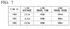
- FIG. 7 is a diagram showing information that the vehicle system 1 acquires from a traffic information management server 300 and link travel speeds calculated on the basis of the information.
- FIG. 8 is a diagram showing an exemplary situation in which notification information is output by an HMI 30 .
- FIG. 9 is a flowchart showing a flow of processing executed by a vehicle system 1 of a second embodiment.
- FIG. 10 is a flow chart showing a flow of processing executed by a traffic information providing system of a third embodiment.
- FIG. 1 is a configuration diagram of a vehicle system 1 including an automated driving control unit 100 .
- a vehicle in which the vehicle system 1 is mounted is, for example, a vehicle such as a two-wheeled vehicle, a three-wheeled vehicle, or a four-wheeled vehicle, and a driving source thereof is an internal combustion engine such as a diesel engine or a gasoline engine, an electric motor, or a combination thereof.
- the electric motor operates using electric power generated by a generator connected to the internal combustion engine or using discharge power of a secondary battery or a fuel cell.
- the vehicle system 1 includes, for example, a camera 10 , a radar device 12 , a finder 14 , an object recognition device 16 , a communication device 20 , a human machine interface (HMI) 30 , a navigation device 50 , a micro-processing unit (MPU) 60 , vehicle sensors 70 , driving operators 80 , an automated driving control unit 100 , a travel driving force output device 200 , a brake device 210 , and a steering device 220 .
- These devices or apparatuses are connected to each other by a multiplex communication line or a serial communication line such as a controller area network (CAN) communication line, a wireless communication network, or the like.
- CAN controller area network
- the “vehicle control system” includes, for example, an acquirer 121 A and a determiner 121 B of an external environment recognizer 121 , a behavior plan generator 123 , and a notification controller 130 . Further, the behavior plan generator 123 , the notification controller 130 , and a travel controller 141 are examples of the “controller.”
- the camera 10 is, for example, a digital camera using a solid-state imaging device such as a charge coupled device (CCD) or a complementary metal oxide semiconductor (CMOS).
- CMOS complementary metal oxide semiconductor
- One or a plurality of cameras 10 are attached to the vehicle in which the vehicle system 1 is mounted (hereinafter referred to as an own vehicle M) at arbitrary locations.
- a camera 10 is attached to an upper portion of a front windshield, a rear surface of a rearview mirror, or the like.
- the camera 10 repeats imaging of the surroundings of the own vehicle M at regular intervals.
- the camera 10 may also be a stereo camera.
- the radar device 12 radiates radio waves such as millimeter waves around the own vehicle M and detects radio waves reflected by an object (reflected waves) to detect at least the position (distance and orientation) of the object.
- radio waves such as millimeter waves around the own vehicle M and detects radio waves reflected by an object (reflected waves) to detect at least the position (distance and orientation) of the object.
- One or a plurality of radar devices 12 may be attached to the own vehicle M at arbitrary locations.
- the radar device 12 may detect the position and speed of an object using a frequency modulated continuous wave (FM-CW) method.
- FM-CW frequency modulated continuous wave
- the finder 14 is a light detection and ranging or laser imaging detection and ranging (LIDAR) finder which measures scattered light from an object in response to illuminated light to detect the distance to the object.
- LIDAR laser imaging detection and ranging
- One or a plurality of finders 14 may be attached to the own vehicle M at arbitrary locations.
- the object recognition device 16 performs a sensor fusion process on results of detection by some or all of the camera 10 , the radar device 12 , and the finder 14 to recognize the position, type, speed, or the like of the object.
- the object recognition device 16 outputs the recognition result to the automated driving control unit 100 .
- the communication device 20 communicates with other vehicles near the own vehicle M using a cellular network, a Wi-Fi network, Bluetooth (registered trademark), dedicated short range communication (DSRC) or the like or communicates with various server devices via wireless base stations.
- a cellular network a Wi-Fi network, Bluetooth (registered trademark), dedicated short range communication (DSRC) or the like
- DSRC dedicated short range communication
- the HMI 30 presents various types of information to an occupant in the own vehicle M and receives an input operation from the occupant.
- the HMI 30 includes various display devices, speakers, buzzers, touch panels, switches, keys, or the like.
- the navigation device 50 includes, for example, a global navigation satellite system (GNSS) receiver 51 , a navigation HMI 52 , and a route determiner 53 and holds first map information 54 in a storage device such as a hard disk drive (HDD) or a flash memory.
- GNSS global navigation satellite system
- the GNSS receiver specifies the position of the own vehicle M on the basis of signals received from GNSS satellites. The position of the own vehicle M may also be specified or supplemented by an inertial navigation system (INS) using the output of the vehicle sensors 70 .
- the navigation HMI 52 includes a display device, a speaker, a touch panel, a key, or the like. The navigation HMI 52 may be partly or wholly shared with the HMI 30 described above.
- the route determiner 53 determines a route from the position of the own vehicle M specified by the GNSS receiver 51 (or an arbitrary input position) to a destination input by the occupant using the navigation HMI 52 by referring to the first map information 54 .
- the first map information 54 is, for example, information representing shapes of roads by links indicating roads and nodes connected by the links.
- the first map information 54 may include curvatures of roads, point of interest (POI) information, or the like.
- POI point of interest
- the route determined by the route determiner 53 is output to the MPU 60 .
- the navigation device 50 may also perform route guidance using the navigation HMI 52 on the basis of the route determined by the route determiner 53 .
- the navigation device 50 may be implemented, for example, by a function of a terminal device such as a smartphone or a tablet possessed by the user.
- the navigation device 50 may also transmit the current position and the destination to a navigation server via the communication device 20 and acquire a route returned from the navigation server.
- the MPU 60 functions, for example, as a recommended lane determiner 61 and holds the second map information 62 in a storage device such as an HDD or a flash memory.
- the recommended lane determiner 61 divides the route provided from the navigation device 50 into a plurality of blocks (for example, into blocks each 100 meters long in the direction in which the own vehicle M travels) and determines a recommended lane for each block by referring to the second map information 62 .
- the recommended lane determiner 61 determines the number of the lane from the left in which to travel. When there is a branch point, a merge point, or the like on the route, the recommended lane determiner 61 determines a recommended lane such that the own vehicle M can travel on a reasonable route for proceeding to the branch destination.
- the second map information 62 is map information with higher accuracy than the first map information 54 .
- the second map information 62 includes, for example, information of the centers of lanes or information of the boundaries of lanes.
- the second map information 62 may also include road information, traffic regulation information, address information (addresses/postal codes), facility information, telephone number information, or the like.
- the road information includes information indicating the types of roads such as expressways, toll roads, national roads, or prefectural roads or information such as the number of lanes of each road, the widths of lanes, the gradients of roads, the positions of roads (three-dimensional coordinates including longitude, latitude and height), the curvatures of curves of lanes, the positions of merge or branch points of lanes, signs installed on roads, or the like.
- the second map information 62 may be updated as needed by accessing another device using the communication device 20 .
- the vehicle sensors 70 include, for example, a vehicle speed sensor that detects the speed of the own vehicle M, an acceleration sensor that detects the acceleration thereof, a yaw rate sensor that detects an angular speed thereof about the vertical axis, an orientation sensor that detects the orientation of the own vehicle M, or the like.
- the driving operators 80 include, for example, an accelerator pedal, a brake pedal, a shift lever, a steering wheel, and other operators. Sensors for detecting the amounts of operation or the presence or absence of operation are attached to the driving operators 80 and detection results thereof are output to either or both of the automated driving control unit 100 or the travel driving force output, brake, and steering devices 200 , 210 , and 220 .
- the automated driving control unit 100 includes, for example, a first controller 120 , the notification controller 130 , and a second controller 140 .
- Each of the functional units of the first controller 120 , the notification controller 130 , and the second controller 140 is implemented by a processor such as a central processing unit (CPU) executing a program (software).
- CPU central processing unit
- Some or all of these functional units may be implemented by hardware such as a large scale integration (LSI), an application specific integrated circuit (ASIC), or a field-programmable gate array (FPGA) or may be implemented by hardware and software in cooperation.
- LSI large scale integration
- ASIC application specific integrated circuit
- FPGA field-programmable gate array
- the first controller 120 includes, for example, the external environment recognizer 121 , an own vehicle position recognizer 122 , and the behavior plan generator 123 .
- the external environment recognizer 121 recognizes states of a nearby vehicle(s) such as the position, speed and acceleration thereof on the basis of information that is input from the camera 10 , the radar device 12 , and the finder 14 directly or via the object recognition device 16 .
- the position of the nearby vehicle may be represented by a representative point such as a center of gravity or a corner of the nearby vehicle or may be represented by a region expressed by a contour of the nearby vehicle.
- the “states” of the nearby vehicle may include an acceleration or jerk of the nearby vehicle or a “behavior state” (for example, whether or not the nearby vehicle is changing or is going to change lanes).
- the external environment recognizer 121 may also recognize the positions of guardrails or utility poles, parked vehicles, pedestrians, and other objects in addition to nearby vehicles.
- the external environment recognizer 121 also includes, for example, the acquirer 121 A, the determiner 121 B, and a storage 121 C.
- the acquirer 121 A acquires information that allows recognition of the speed of other vehicles in the travel direction of the own vehicle M.
- the information that allows recognition of the speed of other vehicles is, for example, a link travel time indicating an average travel time for the link.
- the information that allows recognition of the speed of other vehicles may also be an average speed of vehicles traveling in a link or link travel times or speeds of vehicles acquired in detail for the vehicles traveling in a link. Further, the information that allows recognition of the speed of other vehicles may be information indicating the presence or absence of congestion in a link or a link group.
- the determiner 121 B determines whether or not there is a low speed section whose travel speed is equal to or less than a first predetermined speed in the travel direction of the own vehicle M. For example, the determiner 121 B divides the length of the link by the link travel time to obtain a travel speed and compares this with a first predetermined speed.
- the first predetermined speed is, for example, 60 km/h.
- the storage 121 C is realized, for example, using a random access memory (RAM) or a flash memory.
- the storage 121 C stores the information acquired by the acquirer 121 A or the processing results of the determiner 121 B.
- the own vehicle position recognizer 122 recognizes, for example, the position or attitude of the own vehicle M with respect to the traveling lane.
- FIG. 2 is a diagram showing how the relative position and attitude of the own vehicle M with respect to the traveling lane L 1 are recognized by the own vehicle position recognizer 122 .
- the own vehicle position recognizer 122 recognizes both a deviation OS from a traveling lane center CL of a reference point (for example, the center of gravity) of the own vehicle M and an angle ⁇ formed by the travel direction of the own vehicle M relative to an extension line of the traveling lane center CL as the relative position and attitude of the own vehicle M with respect to the traveling lane L 1 .
- the own vehicle position recognizer 122 may recognize the position of the reference point of the own vehicle M with respect to one of the sides of the own lane L 1 or the like as the relative position of the own vehicle M with respect to the traveling lane.
- the relative position of the own vehicle M recognized by the own vehicle position recognizer 122 is provided to the recommended lane determiner 61 and the behavior plan generator 123 .
- the behavior plan generator 123 determines events which are to be sequentially performed in the automated driving such that the own vehicle M travels in the recommended lane determined by the recommended lane determiner 61 and copes with situations occurring near the own vehicle M.
- the events include a constant-speed travel event which is an event of traveling in the same traveling lane at a constant speed, a following travel event which is an event of following a preceding vehicle, a lane change event, a merging event, a branching event, an emergency stop event, and a handover event which is an event of terminating automated driving and switching to manual driving.
- behaviors for avoidance may sometimes be planned on the basis of situations occurring near the own vehicle M (such as the presence of nearby vehicles and pedestrians or lane narrowing due to road construction).
- the behavior plan generator 123 generates a target trajectory along which the own vehicle M will travel in the future.
- the target trajectory includes, for example, a speed element.
- the target trajectory is generated as a set of target points (trajectory points) to be reached at a plurality of future reference times which are set at intervals of a predetermined sampling time (for example, about tenths of a second). Therefore, when the interval between trajectory points is great, this means that the vehicle travels at a high speed in the section between the trajectory points.
- FIG. 3 is a diagram showing how a target trajectory is generated on the basis of a recommended lane.
- the recommended lane is set to be convenient for traveling along the route to the destination.
- the behavior plan generator 123 activates a lane change event, a branching event, a merging event, or the like.
- an avoidance trajectory is generated as shown in FIG. 3 .
- the behavior plan generator 123 generates a plurality of candidate target trajectories and selects an optimum target trajectory at a given point in time from the viewpoint of safety and efficiency.
- the travel controller 141 in the second controller 140 controls the travel driving force output device 200 , the brake device 210 , and the steering device 220 such that the own vehicle M passes along the target trajectory generated by the behavior plan generator 123 at scheduled times.
- the automated driving which is performed mainly by the first controller 120 is executed in one of a plurality of automated driving modes.
- the automated driving modes include an automated driving mode which is executed at a second predetermined speed (for example, 60 km/h) or less.
- a second predetermined speed for example, 60 km/h
- An example of this is a low speed following travel (traffic jam pilot: TJP) in which the own vehicle M follows a preceding vehicle at the time of congestion.
- TJP traffic jam pilot
- safe automated driving can be realized by following a preceding vehicle on a congested freeway.
- the first predetermined speed and the second predetermined speed may be equal or the first predetermined speed may be slightly higher than the second predetermined speed.
- the low speed following travel In the low speed following travel, lane change of the own vehicle M by the behavior plan generator 123 is prohibited. This is because congestion of vehicles blocks recognition of the nearby situation of the own vehicle M (in particular, the presence of two-wheeled vehicles overtaking the own vehicle M from behind the own vehicle M). The low speed following travel is canceled, for example, when the travel speed of the own vehicle M exceeds the second predetermined speed.
- the own vehicle M can change lanes according to events, which are sequentially executed in automated driving, and the nearby situation of the own vehicle M. This is because when the own vehicle M travels at a speed higher than the second predetermined speed, a certain distance or more is secured as the inter-vehicle distance between the own vehicle M and nearby vehicles and the own vehicle M can recognize its nearby situation without being blocked by other vehicles m.
- the notification controller 130 causes an output unit (such as various display devices or a speaker) included in the HMI 30 or the navigation HMI 52 to output predetermined information, for example, when the own vehicle M is expected to reach a low speed section within a predetermined time or there is a low speed section within a predetermined distance in the travel direction of the own vehicle M.
- the predetermined information is, for example, information indicating that a low speed section will be reached in a predetermined time.
- the travel driving force output device 200 outputs a travel driving force (torque) required for the vehicle to travel to driving wheels.
- the travel driving force output device 200 includes, for example, a combination of an internal combustion engine, an electric motor, a transmission, and the like and an ECU that controls them.
- the ECU controls the above constituent elements according to information input from the travel controller 141 or information input from the driving operators 80 .
- FIG. 4 is a diagram showing an example of a traffic information providing system including an own vehicle M in which the vehicle system 1 is mounted.
- the traffic information providing system includes the own vehicle M, other vehicles m- 1 to m-k (where “k” is an arbitrary natural number), and a traffic information management server 300 .
- the other vehicles m- 1 to m-k are referred to as “other vehicles m” unless otherwise distinguished.
- at least a communication device that communicates with the traffic information management server 300 and a device having a function of specifying the position of the vehicle are mounted in some or all of the other vehicles m.
- the other vehicles m in which these devices are mounted transmit vehicle position information to the traffic information management server 300 .
- the traffic information management server 300 and vehicles including one or both of the own vehicle M and another vehicle m perform communication with each other using a network NW.
- the network NW is, for example, a cellular network, a Wi-Fi network, a wide area network (WAN), a local area network (LAN), or the Internet.
- the own vehicle M at least acquires information transmitted from the traffic information management server 300 by receiving radio waves in a preset frequency band.
- the traffic information management server 300 manages traffic information based on information transmitted by vehicles and detection results of vehicle detection sensors (for example, cameras) installed on a road. In addition, the traffic information management server 300 distributes the managed traffic information to vehicles at predetermined intervals using the network NW described above or transmits traffic information to a vehicle in response to a request from the vehicle.
- vehicle detection sensors for example, cameras
- the traffic information management server 300 includes, for example, a communicator 302 , a server controller 304 , and a server storage 306 .
- the server controller 304 is implemented by a processor executing a program.
- the server controller 304 may be implemented by hardware such as an LSI or an ASIC or may be implemented by a combination of software and hardware.
- the server storage 306 is realized by a ROM, a RAM, an HDD, a flash memory, or the like.
- the communicator 302 communicates with a vehicle to acquire information.
- the communicator 302 acquires a vehicle ID of the vehicle (identification information of the vehicle) and position information indicating the position of the vehicle together with the transmission time at which the information was transmitted.
- vehicle information these pieces of information are referred to as “vehicle information.”
- the communicator 302 acquires an image captured by the camera.
- the camera is installed on a road.
- the server controller 304 recognizes information described on a license plate through image analysis. This specifies a vehicle which has passed that location and thus a link travel time thereof is acquired by the traffic information management server 300 .
- the server controller 304 stores the vehicle information in the server storage unit 306 .
- FIG. 5 is a diagram showing an example of the vehicle information 318 stored in the server storage 306 .
- position information indicating the position of the vehicle is a link ID identifying a link indicating a road.
- the link ID is, for example, an ID assigned to each lane on a road.
- a link ID may also be assigned to each travel direction on a road or to each road. It is assumed that the link IDs are the same as link IDs assigned to roads in the first map information 54 and the second map information 62 included in the vehicle system 1 or IDs whose associated relationships are recognizable by the vehicle or the traffic information management server 300 .
- the server controller 304 transmits information relating to the vehicle information 318 to the own vehicle M in response to a request from the own vehicle M.
- the server controller 304 derives a link travel time for a link designated by the request by referring to the vehicle information 318 using the link designated by the request as a search key and provides the derived link travel time to the own vehicle M.
- the server controller 304 may also transmit, to the own vehicle M, link travel times of vehicles acquired in detail for the vehicles traveling in a link.
- the server controller 304 may calculate the link travel speed of each vehicle which has traveled in the link on the basis of the link travel times of the vehicles acquired in detail for the vehicles traveling in the link and the link distance and transmit information on the calculated travel speed to the own vehicle M or transmit information on an average speed of the link to the own vehicle M.
- the server controller 304 may derive information indicating the presence or absence of congestion in a link or a link group and transmit the information indicating the presence or absence of congestion to the own vehicle M. In this case, while the reference for congestion may differ from the second predetermined speed, the vehicle system 1 may use information indicating the presence or absence of congestion on the safe side.
- the server controller 304 may derive a route from the current position of the own vehicle M to the destination by referring to the map information and the traffic information stored in the traffic information management server 300 and transmit the derived route to the own vehicle M.
- the route search request from the own vehicle M is, for example, a request to search for a route by which the destination can be reached in the shortest time from the current location
- the server controller 304 derives a link travel time on the basis of the vehicle information 318 and searches for a route by which the destination can be reached in the shortest time with reference to the derived link travel time and the map information.
- FIG. 6 is a flowchart showing a flow of processing executed by the vehicle system 1 and the traffic information management server 300 .
- the acquirer 121 A of the vehicle system 1 acquires the travel direction of the own vehicle M on the map from the behavior plan generator 123 (step S 100 ).
- the acquirer 121 A designates one or more links associated with a road in the travel direction of the own vehicle M (a road on a route toward the destination) and requests that the traffic information management server 300 transmit link travel times associated with the designated links (step S 102 ).
- the traffic information management server 300 transmits the travel times of the designated links to the own vehicle M in response to the above request (step S 200 ).
- the acquirer 121 A acquires, from the traffic information management server 300 , the travel times of the links included in the route in the travel direction of the own vehicle M on the map acquired in step S 100 .
- the acquirer 121 A calculates the speeds of vehicles in the links on the basis of the link distances and the acquired link travel times (step S 104 ).
- FIG. 7 is a diagram showing information that the vehicle system 1 acquires from the traffic information management server 300 and link travel speeds calculated on the basis of the information.
- the acquirer 121 A causes the storage 121 C to store link IDs, link distances, and link travel times acquired from the traffic information management server 300 in association with each other and adds results calculated in step S 104 to them. Then, if there is a section (link) whose link travel speed is equal to or less than the first predetermined speed, the determiner 121 B determines that the section (link) is a low speed section. For example, in the example of FIG. 7 , it is determined that links L 1001 and L 1002 are low speed sections.
- the determiner 121 B may perform the same determination as above after obtaining an average value of the vehicles or may determine that the section is a low speed section if the proportion of vehicles traveling at speeds equal to or less than the first predetermined speed is equal to or more than a predetermined value.
- the determiner 121 B determines whether or not there is a low speed section on the basis of the speed information stored in the storage 121 C (step S 106 ). If there is no low speed section, the processing of one routine of this flowchart ends.
- the notification controller 130 determines whether or not the own vehicle M will reach the low speed section in a predetermined time on the basis of the current location of the own vehicle M and the speed of the own vehicle M (step S 108 ). Instead of “determining whether or not the own vehicle M will reach the low speed section in the predetermined time,” the notification controller 130 may “determine whether or not the distance from the own vehicle M to the low speed section is within a predetermined distance.” If the own vehicle M will not reach the low speed section in the predetermined time, the processing of one routine of this flowchart ends.
- the notification controller 130 causes the HMI 30 to output notification information indicating that the low speed section will be reached in the predetermined time to notify the occupant of the own vehicle M of the information (step S 110 ). Then, the processing of one routine of this flowchart ends.
- FIG. 8 is a diagram showing an exemplary situation in which notification information is output by the HMI 30 . It is assumed that the own vehicle M is traveling in a lane L 1 at a speed higher than the second predetermined speed by automated driving. When the own vehicle M has reached a position from which it will reach a low speed section in the predetermined time (a position that is a distance Th before the start point of the low speed section in the drawing), the notification controller 130 causes the HMI 30 to output notification information. This allows the occupant of the own vehicle M to perceive that the own vehicle M will reach a low speed section in the predetermined time, that is, a low speed following travel during which lane change by the behavior plan generator 123 is prohibited is expected to be executed in the predetermined time.
- the occupant (driver) of the own vehicle M can cause the own vehicle M to change lanes to a lane L 2 connected to a branch road L 3 toward the destination of the own vehicle M before reaching the low speed section.
- Lane change in this case may be performed manually after switching to manual driving by override or may be performed by auto lane change with a certain operation of the occupant (for example, an operation of a turn signal) as a trigger.
- the notification controller 130 may cause the HMI 30 to output notification information while changing the degree of output of the notification information in a stepwise manner.
- the notification controller 130 changes the degree of output of the notification information in a stepwise manner, for example, according to the distance between the own vehicle M and the low speed section or according to the time within which the own vehicle M will reach the low speed section. That is, the notification controller 130 causes the HMI 30 to output the notification information such that the degree of output of the notification information increases as the distance between the own vehicle M and the low speed section decreases or the time within which the own vehicle M will reach the low speed section decreases.
- the notification controller 130 may also cause the HMI 30 to display the distance between the own vehicle M and the low speed section and/or the time within which the own vehicle M will reach the low speed section.
- the notification controller 130 may cause the HMI 30 to output the notification information only when the own vehicle M needs to change lanes.
- the own vehicle M needs to change lanes when the own vehicle M is not traveling in the lane L 2 connected to the branch road L 3 (i.e. the own vehicle M is traveling in the lane L 1 ) if there is a branch point for entering the branch road L 3 from the lane L 2 of a main line when the own vehicle M is to travel along a predetermined route as shown in FIG. 8 above.
- the notification controller 130 may cause the HMI 30 to output notification information when there is a branch point. This allows the occupant of the own vehicle M to perceive that there is a low speed section. Therefore, it is possible to predict that it will be difficult for the own vehicle M to change lanes to the branch road L 3 if it changes lanes from the lane L 2 to the lane L 1 . As a result, on the basis of the prediction, the occupant of the own vehicle M can determine whether or not to change lanes with a certain operation as a trigger.
- the acquirer 121 A configured to acquire information that allows recognition of the speed of other vehicles m present in the travel direction of the own vehicle M
- the determiner 121 B configured to determine whether or not there is a low speed section whose travel speed is equal to or less than the first predetermined speed in the travel direction of the own vehicle M on the basis of the information acquired by the acquirer 121 A
- the automated driving control unit 100 capable of executing an automated driving mode which is executed at the second predetermined speed or less, the automated driving control unit 100 including the notification controller 130 configured to perform causing the HMI 30 to output predetermined information as predetermined control before the own vehicle M reaches the low speed section that has been determined as being present by the determiner 121 B, are provided.
- the occupant of the own vehicle M can perceive the presence of a section whose travel speed may be equal to or less than the second predetermined speed and can reflect the perception in control of the own vehicle M before reaching the section.
- a second embodiment will be described below.
- the notification controller 130 causes the HMI 30 to output notification information.
- the behavior plan generator 123 causes the own vehicle M to change lanes.
- differences from the first embodiment will be mainly described and descriptions of functions or the like the same as in the first embodiment will be omitted.
- the behavior plan generator 123 and the travel controller 141 are examples of the “controller.”
- FIG. 9 is a flowchart showing a flow of processing executed by the vehicle system 1 of the second embodiment.
- the acquirer 121 A acquires the travel direction of the own vehicle M on the map from the behavior plan generator 123 (step S 300 ).
- the acquirer 121 A designates one or more links associated with the travel direction of the own vehicle M and requests that the traffic information management server 300 transmit link travel times associated with the designated links (step S 302 ).
- the traffic information management server 300 transmits the travel times of the designated links to the own vehicle M in response to the above request (step S 400 ).
- the acquirer 121 A calculates the speeds of vehicles in the links on the basis of the link distances and the acquired travel times (step S 304 ).
- the determiner 121 B determines whether or not there is a low speed section in the travel direction of the vehicle on the basis of the information stored in the storage 121 C (step S 306 ). If there is no low speed section, the processing of one routine of this flowchart ends.
- the determiner 121 B determines whether or not the own vehicle M will reach the low speed section in a predetermined time on the basis of the current location of the own vehicle M and the speed of the own vehicle M (step S 308 ). If the own vehicle M will not reach the low speed section in the predetermined time, the processing of one routine of this flowchart ends.
- the determiner 121 B determines whether or not it is necessary for the own vehicle M to change lanes (step S 310 ).
- the behavior plan generator 123 performs lane change of the own vehicle M before the own vehicle M reaches the low speed section (step S 312 ). More strictly, the behavior plan generator 123 completes the lane change of the own vehicle M before the own vehicle M reaches the low speed section. In this case, even if lane change was planned to be performed in the low speed section, the behavior plan generator 123 generates a behavior plan for causing the own vehicle M to complete the lane change before reaching the low speed section. If it is not determined that it is necessary for the own vehicle M to change lanes, the processing of one routine of this flowchart ends.
- the processing of one routine in the flowchart ends if it is determined in step S 310 that it is not necessary to change lanes in step S 310 , but instead, for example, the behavior plan controller 123 may prohibit the execution of the lane change after it is determined in step S 310 that it is not necessary to change lanes.
- the behavior plan controller 123 may prohibit the execution of the lane change after it is determined in step S 310 that it is not necessary to change lanes.
- the behavior plan generator 123 prohibits lane change from the lane L 2 to the lane L 1 . This prevents the occurrence of a situation in which the own vehicle M cannot return to the lane L 2 by automated driving since it has entered the low speed section. Even when the lane change is prohibited, a resulting lane change for obstacle avoidance or the like may be permitted.
- the vehicle system 1 includes the behavior plan generator 123 configured to cause the own vehicle M to perform lane change as predetermined control before the own vehicle M reaches a low speed section that has been determined as being present by the determiner 121 B and therefore the own vehicle M can more reliably enter the branch destination by automated driving.
- the traffic information management server 300 transmits, to the own vehicle M, information on a low speed section present within the predetermined distance from the current location of the own vehicle M (step S 600 ). If no low speed section is present within the predetermined distance from the current location of the own vehicle M, the traffic information management server 300 transmits information indicating that no low speed section is present to the own vehicle M.
- the determiner 121 B determines whether or not the own vehicle M will reach the low speed section in a predetermined time on the basis of the current location of the own vehicle M and the speed of the own vehicle M (step S 506 ). If the own vehicle M will not reach the low speed section in the predetermined time, the processing of one routine of this flowchart ends.
- the determiner 121 B may determine whether or not it is necessary for the own vehicle M to change lanes. If the determiner 121 B determines that it is necessary to change lanes, the behavior plan generator 123 performs the lane change of the own vehicle M before the own vehicle M reaches the low speed section. More strictly, the behavior plan generator 123 completes the lane change of the own vehicle M before the own vehicle M reaches the low speed section.
- the notification controller 130 may also cause the HMI 30 to output notification information indicating that the low speed section will be reached in the predetermined time if the determiner 121 B determines that it is necessary to change lanes and the first controller 120 determines that it is not possible to perform lane change by automated driving on the basis of the nearby situations.
- the traffic information management server 300 transmits information on the low speed section to the own vehicle M in response to a request from the own vehicle M.
- the traffic information management server 300 may acquire the position of the own vehicle M from the own vehicle M at predetermined intervals and transmit information indicating that the own vehicle M is approaching a low speed section to the own vehicle M when the own vehicle M has reached a predetermined distance or less before the low speed section or at a predetermined time before the own vehicle M reaches the low speed section.
- the own vehicle M causes the HMI 30 to output notification information upon acquiring the information indicating that it is approaching the low speed section from the traffic information management server 300 .
- the vehicle system 1 acquires a low speed section present in the travel direction of the own vehicle M from the traffic information management server 300 and executes predetermined control on the basis of the acquired information and thus it is possible to reduce a processing load while achieving the same advantages as those of the first embodiment.
Landscapes
- Engineering & Computer Science (AREA)
- Automation & Control Theory (AREA)
- Mechanical Engineering (AREA)
- Transportation (AREA)
- Radar, Positioning & Navigation (AREA)
- Remote Sensing (AREA)
- Human Computer Interaction (AREA)
- General Physics & Mathematics (AREA)
- Physics & Mathematics (AREA)
- Chemical & Material Sciences (AREA)
- Combustion & Propulsion (AREA)
- Health & Medical Sciences (AREA)
- General Health & Medical Sciences (AREA)
- Social Psychology (AREA)
- Traffic Control Systems (AREA)
- Aviation & Aerospace Engineering (AREA)
- Control Of Driving Devices And Active Controlling Of Vehicle (AREA)
- Navigation (AREA)
Abstract
Description
Claims (17)
Applications Claiming Priority (1)
| Application Number | Priority Date | Filing Date | Title |
|---|---|---|---|
| PCT/JP2017/002281 WO2018138765A1 (en) | 2017-01-24 | 2017-01-24 | Vehicle control system, vehicle control method, and vehicle control program |
Publications (2)
| Publication Number | Publication Date |
|---|---|
| US20190354108A1 US20190354108A1 (en) | 2019-11-21 |
| US11307591B2 true US11307591B2 (en) | 2022-04-19 |
Family
ID=62979119
Family Applications (1)
| Application Number | Title | Priority Date | Filing Date |
|---|---|---|---|
| US16/469,694 Active 2037-04-17 US11307591B2 (en) | 2017-01-24 | 2017-01-24 | Vehicle control system, vehicle control method, and vehicle control program |
Country Status (4)
| Country | Link |
|---|---|
| US (1) | US11307591B2 (en) |
| JP (1) | JP6676196B2 (en) |
| CN (1) | CN110087964B (en) |
| WO (1) | WO2018138765A1 (en) |
Families Citing this family (12)
| Publication number | Priority date | Publication date | Assignee | Title |
|---|---|---|---|---|
| JP6834693B2 (en) * | 2017-03-30 | 2021-02-24 | アイシン・エィ・ダブリュ株式会社 | Communication terminals, mobile guidance systems and computer programs |
| JP6990160B2 (en) * | 2018-09-28 | 2022-01-12 | 株式会社Subaru | Automatic driving support device |
| EP3921988B1 (en) * | 2019-02-06 | 2023-05-10 | Telefonaktiebolaget LM Ericsson (publ) | Detecting short duration attacks on connected vehicles |
| JP6892208B2 (en) * | 2019-02-27 | 2021-06-23 | 本田技研工業株式会社 | Vehicle control device |
| WO2020230303A1 (en) * | 2019-05-15 | 2020-11-19 | 日産自動車株式会社 | Traveling control method and traveling control device for vehicle |
| CN112208531B (en) | 2019-07-09 | 2024-04-30 | 本田技研工业株式会社 | Vehicle control device, vehicle control method, and storage medium |
| JP7049391B2 (en) * | 2019-07-09 | 2022-04-06 | 本田技研工業株式会社 | Vehicle control devices, vehicle control methods, and programs |
| JP2021047798A (en) * | 2019-09-20 | 2021-03-25 | いすゞ自動車株式会社 | Lane change control device and vehicle |
| CN113492870A (en) * | 2020-03-18 | 2021-10-12 | 奥迪股份公司 | Vehicle driving assistance system, method, vehicle, and storage medium |
| CN111595358B (en) | 2020-06-05 | 2022-03-29 | 百度在线网络技术(北京)有限公司 | Navigation data processing method, route guidance method, device and storage medium |
| JP7464454B2 (en) * | 2020-06-15 | 2024-04-09 | トヨタ自動車株式会社 | Vehicle control device and vehicle control method |
| CN114407899B (en) * | 2021-01-11 | 2023-06-09 | 广东科学技术职业学院 | Method for controlling vehicle to be integrated into target lane |
Citations (20)
| Publication number | Priority date | Publication date | Assignee | Title |
|---|---|---|---|---|
| JPH05266399A (en) | 1992-03-19 | 1993-10-15 | Hitachi Ltd | Travel controller by inter-vehicle communication |
| US20020018003A1 (en) | 2000-02-12 | 2002-02-14 | Peter Andreas | Method for controlling the speed and distance of a motor vehicle |
| JP2005173663A (en) | 2003-12-05 | 2005-06-30 | Fuji Heavy Ind Ltd | Traveling control device for vehicle |
| JP2006248334A (en) | 2005-03-09 | 2006-09-21 | Toyota Motor Corp | Vehicle running control device |
| JP2010143551A (en) | 2008-12-22 | 2010-07-01 | Toyota Motor Corp | Driving assistance system |
| WO2010082353A1 (en) * | 2009-01-19 | 2010-07-22 | トヨタ自動車株式会社 | Vehicle control device |
| JP2011162132A (en) | 2010-02-12 | 2011-08-25 | Toyota Motor Corp | Automatic driving device |
| WO2011158347A1 (en) | 2010-06-16 | 2011-12-22 | トヨタ自動車株式会社 | Driving assistance device |
| JP2013232241A (en) | 2008-07-10 | 2013-11-14 | Mitsubishi Electric Corp | Leading vehicle-mounted processor unit and subsequent vehicle-mounted processor unit |
| JP2015168406A (en) | 2014-03-11 | 2015-09-28 | トヨタ自動車株式会社 | Lane change assist system |
| CN105539441A (en) | 2014-10-27 | 2016-05-04 | 富士重工业株式会社 | Travel control apparatus for vehicle |
| WO2016092796A1 (en) * | 2014-12-12 | 2016-06-16 | Sony Corporation | Automatic driving control device and automatic driving control method, and program |
| WO2016113890A1 (en) | 2015-01-16 | 2016-07-21 | 三菱電機株式会社 | Travel plan creation device and travel plan changing method |
| JP2016146129A (en) * | 2015-02-09 | 2016-08-12 | アイシン・エィ・ダブリュ株式会社 | Convoy traveling management device and convoy traveling management program |
| CN106030677A (en) | 2014-09-29 | 2016-10-12 | 日立建机株式会社 | Traffic management control device |
| US20160307444A1 (en) | 2015-04-14 | 2016-10-20 | Honda Motor Co., Ltd. | Driving support method, program, and driving support device |
| US20180143028A1 (en) * | 2016-11-23 | 2018-05-24 | Hyundai Motor Company | Apparatus and method for controlling path of vehicle |
| US20180181135A1 (en) * | 2016-12-27 | 2018-06-28 | Toyota Jidosha Kabushiki Kaisha | Autonomous driving device for vehicle |
| US20190322285A1 (en) * | 2016-10-13 | 2019-10-24 | Valeo Schalter Und Sensoren Gmbh | Categorization of vehicles in the surroundings of a motor vehicle |
| US20200272147A1 (en) * | 2016-12-13 | 2020-08-27 | Toyota Jidosha Kabushiki Kaisha | Blinker judgment device and autonomous driving system |
Family Cites Families (7)
| Publication number | Priority date | Publication date | Assignee | Title |
|---|---|---|---|---|
| DE19757063A1 (en) * | 1997-12-20 | 1999-06-24 | Bayerische Motoren Werke Ag | Safety speed control system for vehicle |
| JP6217412B2 (en) * | 2014-01-29 | 2017-10-25 | アイシン・エィ・ダブリュ株式会社 | Automatic driving support device, automatic driving support method and program |
| US9229453B1 (en) * | 2014-08-29 | 2016-01-05 | GM Global Technology Operations LLC | Unified motion planner for autonomous driving vehicle in avoiding the moving obstacle |
| JP2016132421A (en) * | 2015-01-22 | 2016-07-25 | トヨタ自動車株式会社 | Automatic drive unit |
| DE102015208007A1 (en) * | 2015-04-30 | 2016-11-03 | Conti Temic Microelectronic Gmbh | Method for carrying out a lane change in a motor vehicle |
| JP6332170B2 (en) * | 2015-07-01 | 2018-05-30 | トヨタ自動車株式会社 | Automatic operation control device |
| JP6376059B2 (en) * | 2015-07-06 | 2018-08-22 | トヨタ自動車株式会社 | Control device for autonomous driving vehicle |
-
2017
- 2017-01-24 WO PCT/JP2017/002281 patent/WO2018138765A1/en active Application Filing
- 2017-01-24 JP JP2018563959A patent/JP6676196B2/en active Active
- 2017-01-24 US US16/469,694 patent/US11307591B2/en active Active
- 2017-01-24 CN CN201780079021.9A patent/CN110087964B/en active Active
Patent Citations (22)
| Publication number | Priority date | Publication date | Assignee | Title |
|---|---|---|---|---|
| JPH05266399A (en) | 1992-03-19 | 1993-10-15 | Hitachi Ltd | Travel controller by inter-vehicle communication |
| US20020018003A1 (en) | 2000-02-12 | 2002-02-14 | Peter Andreas | Method for controlling the speed and distance of a motor vehicle |
| JP2005173663A (en) | 2003-12-05 | 2005-06-30 | Fuji Heavy Ind Ltd | Traveling control device for vehicle |
| JP2006248334A (en) | 2005-03-09 | 2006-09-21 | Toyota Motor Corp | Vehicle running control device |
| JP2013232241A (en) | 2008-07-10 | 2013-11-14 | Mitsubishi Electric Corp | Leading vehicle-mounted processor unit and subsequent vehicle-mounted processor unit |
| JP2010143551A (en) | 2008-12-22 | 2010-07-01 | Toyota Motor Corp | Driving assistance system |
| WO2010082353A1 (en) * | 2009-01-19 | 2010-07-22 | トヨタ自動車株式会社 | Vehicle control device |
| JP2011162132A (en) | 2010-02-12 | 2011-08-25 | Toyota Motor Corp | Automatic driving device |
| WO2011158347A1 (en) | 2010-06-16 | 2011-12-22 | トヨタ自動車株式会社 | Driving assistance device |
| US20130110343A1 (en) | 2010-06-16 | 2013-05-02 | Kentaro Ichikawa | Driving assistance device |
| JP2015168406A (en) | 2014-03-11 | 2015-09-28 | トヨタ自動車株式会社 | Lane change assist system |
| CN106030677A (en) | 2014-09-29 | 2016-10-12 | 日立建机株式会社 | Traffic management control device |
| CN105539441A (en) | 2014-10-27 | 2016-05-04 | 富士重工业株式会社 | Travel control apparatus for vehicle |
| WO2016092796A1 (en) * | 2014-12-12 | 2016-06-16 | Sony Corporation | Automatic driving control device and automatic driving control method, and program |
| WO2016113890A1 (en) | 2015-01-16 | 2016-07-21 | 三菱電機株式会社 | Travel plan creation device and travel plan changing method |
| JP2016146129A (en) * | 2015-02-09 | 2016-08-12 | アイシン・エィ・ダブリュ株式会社 | Convoy traveling management device and convoy traveling management program |
| US20160307444A1 (en) | 2015-04-14 | 2016-10-20 | Honda Motor Co., Ltd. | Driving support method, program, and driving support device |
| JP2016201059A (en) | 2015-04-14 | 2016-12-01 | 本田技研工業株式会社 | Travel assist method, program, and travel assist apparatus |
| US20190322285A1 (en) * | 2016-10-13 | 2019-10-24 | Valeo Schalter Und Sensoren Gmbh | Categorization of vehicles in the surroundings of a motor vehicle |
| US20180143028A1 (en) * | 2016-11-23 | 2018-05-24 | Hyundai Motor Company | Apparatus and method for controlling path of vehicle |
| US20200272147A1 (en) * | 2016-12-13 | 2020-08-27 | Toyota Jidosha Kabushiki Kaisha | Blinker judgment device and autonomous driving system |
| US20180181135A1 (en) * | 2016-12-27 | 2018-06-28 | Toyota Jidosha Kabushiki Kaisha | Autonomous driving device for vehicle |
Non-Patent Citations (7)
| Title |
|---|
| Chinese Office Action for Chinese Patent Application No. 201780079021.9 dated Oct. 20, 2021. |
| International Search Report and Written Opinion for International Application No. PCT/JP2017/002281 dated Mar. 28, 2017, 12 pgs. |
| Japanese Office Action for Japanese Patent Application No. 2018-563959 dated Jan. 7, 2020. |
| Machine translation of JP-2013232241-A, Tsuda Yoshiaki, Nov. 2013 (Year: 2013). * |
| Machine translation of JP-2016146129-A, Kondo Yoshito (Year: 2016). * |
| Machine translation of WO-2010082353-A1, Sato Kunihito, Jul. 2010 (Year: 2010). * |
| Machine trasnlation of JP-2006248334-A, Makino, Yasushi (Year: 2006). * |
Also Published As
| Publication number | Publication date |
|---|---|
| JPWO2018138765A1 (en) | 2019-11-07 |
| WO2018138765A1 (en) | 2018-08-02 |
| JP6676196B2 (en) | 2020-04-08 |
| CN110087964B (en) | 2022-05-24 |
| US20190354108A1 (en) | 2019-11-21 |
| CN110087964A (en) | 2019-08-02 |
Similar Documents
| Publication | Publication Date | Title |
|---|---|---|
| US11307591B2 (en) | Vehicle control system, vehicle control method, and vehicle control program | |
| US11192554B2 (en) | Vehicle control system, vehicle control method, and vehicle control program | |
| US10783789B2 (en) | Lane change estimation device, lane change estimation method, and storage medium | |
| US11173906B2 (en) | Vehicle control system, vehicle control method, and storage medium | |
| JP6817334B2 (en) | Vehicle control systems, vehicle control methods, and vehicle control programs | |
| US11299161B2 (en) | Vehicle control system, vehicle control method, and storage medium | |
| US11242055B2 (en) | Vehicle control system and vehicle control method | |
| CN109426263B (en) | Vehicle control device, vehicle control method, and storage medium | |
| US20200180638A1 (en) | Vehicle control system and vehicle control method | |
| JP6649512B2 (en) | Vehicle control system, vehicle control method, and vehicle control program | |
| US20190359209A1 (en) | Vehicle control device, vehicle control method, and vehicle control program | |
| US11299152B2 (en) | Vehicle control system, vehicle control method, and storage medium | |
| JP6663038B2 (en) | Vehicle control system, vehicle control method, and vehicle control program | |
| JP6821791B2 (en) | Vehicle control systems, vehicle control methods, and vehicle control programs | |
| JP6692935B2 (en) | Vehicle control device, vehicle control method, and vehicle control program | |
| US11230290B2 (en) | Vehicle control device, vehicle control method, and program | |
| US10564000B2 (en) | Information display device, information display method, and information display program | |
| JP6705022B2 (en) | Vehicle control system, vehicle control method, and vehicle control program | |
| CN110462338B (en) | Vehicle control system, server device, vehicle control method, and storage medium |
Legal Events
| Date | Code | Title | Description |
|---|---|---|---|
| AS | Assignment |
Owner name: HONDA MOTOR CO., LTD., JAPAN Free format text: ASSIGNMENT OF ASSIGNORS INTEREST;ASSIGNORS:OKAJIMA, NOBORU;IWASA, TATSUYA;NAKAMURA, YUSUKE;REEL/FRAME:049466/0503 Effective date: 20190607 |
|
| FEPP | Fee payment procedure |
Free format text: ENTITY STATUS SET TO UNDISCOUNTED (ORIGINAL EVENT CODE: BIG.); ENTITY STATUS OF PATENT OWNER: LARGE ENTITY |
|
| STPP | Information on status: patent application and granting procedure in general |
Free format text: NON FINAL ACTION MAILED |
|
| STPP | Information on status: patent application and granting procedure in general |
Free format text: RESPONSE TO NON-FINAL OFFICE ACTION ENTERED AND FORWARDED TO EXAMINER |
|
| STPP | Information on status: patent application and granting procedure in general |
Free format text: FINAL REJECTION MAILED |
|
| STPP | Information on status: patent application and granting procedure in general |
Free format text: RESPONSE AFTER FINAL ACTION FORWARDED TO EXAMINER |
|
| STPP | Information on status: patent application and granting procedure in general |
Free format text: NOTICE OF ALLOWANCE MAILED -- APPLICATION RECEIVED IN OFFICE OF PUBLICATIONS |
|
| STPP | Information on status: patent application and granting procedure in general |
Free format text: AWAITING TC RESP., ISSUE FEE NOT PAID |
|
| STPP | Information on status: patent application and granting procedure in general |
Free format text: NOTICE OF ALLOWANCE MAILED -- APPLICATION RECEIVED IN OFFICE OF PUBLICATIONS |
|
| STPP | Information on status: patent application and granting procedure in general |
Free format text: PUBLICATIONS -- ISSUE FEE PAYMENT VERIFIED |
|
| STCF | Information on status: patent grant |
Free format text: PATENTED CASE |