US11276378B2 - Vehicle operation system and computer readable non-transitory storage medium - Google Patents

Vehicle operation system and computer readable non-transitory storage medium Download PDF

Info

Publication number
US11276378B2
US11276378B2 US16/325,598 US201716325598A US11276378B2 US 11276378 B2 US11276378 B2 US 11276378B2 US 201716325598 A US201716325598 A US 201716325598A US 11276378 B2 US11276378 B2 US 11276378B2
Authority
US
United States
Prior art keywords
display
steering wheel
driver
vehicle
display information
Prior art date
Legal status (The legal status is an assumption and is not a legal conclusion. Google has not performed a legal analysis and makes no representation as to the accuracy of the status listed.)
Active, expires
Application number
US16/325,598
Other versions
US20210280157A1 (en
Inventor
Wataru Mizuno
Kazutomo Tsuchikawa
Daisuke Suzuki
Yoshinori Watanabe
Taiichiro Ichimaru
Daisuke NAMEKAWA
Current Assignee (The listed assignees may be inaccurate. Google has not performed a legal analysis and makes no representation or warranty as to the accuracy of the list.)
Denso Corp
Original Assignee
Denso Corp
Priority date (The priority date is an assumption and is not a legal conclusion. Google has not performed a legal analysis and makes no representation as to the accuracy of the date listed.)
Filing date
Publication date
Application filed by Denso Corp filed Critical Denso Corp
Assigned to DENSO CORPORATION reassignment DENSO CORPORATION ASSIGNMENT OF ASSIGNORS INTEREST (SEE DOCUMENT FOR DETAILS). Assignors: MIZUNO, WATARU, ICHIMARU, Taiichiro, SUZUKI, DAISUKE, WATANABE, YOSHINORI, NAMEKAWA, Daisuke, TSUCHIKAWA, KAZUTOMO
Publication of US20210280157A1 publication Critical patent/US20210280157A1/en
Application granted granted Critical
Publication of US11276378B2 publication Critical patent/US11276378B2/en
Active legal-status Critical Current
Adjusted expiration legal-status Critical

Links

Images

Classifications

    • GPHYSICS
    • G09EDUCATION; CRYPTOGRAPHY; DISPLAY; ADVERTISING; SEALS
    • G09GARRANGEMENTS OR CIRCUITS FOR CONTROL OF INDICATING DEVICES USING STATIC MEANS TO PRESENT VARIABLE INFORMATION
    • G09G5/00Control arrangements or circuits for visual indicators common to cathode-ray tube indicators and other visual indicators
    • G09G5/36Control arrangements or circuits for visual indicators common to cathode-ray tube indicators and other visual indicators characterised by the display of a graphic pattern, e.g. using an all-points-addressable [APA] memory
    • G09G5/38Control arrangements or circuits for visual indicators common to cathode-ray tube indicators and other visual indicators characterised by the display of a graphic pattern, e.g. using an all-points-addressable [APA] memory with means for controlling the display position
    • BPERFORMING OPERATIONS; TRANSPORTING
    • B60VEHICLES IN GENERAL
    • B60KARRANGEMENT OR MOUNTING OF PROPULSION UNITS OR OF TRANSMISSIONS IN VEHICLES; ARRANGEMENT OR MOUNTING OF PLURAL DIVERSE PRIME-MOVERS IN VEHICLES; AUXILIARY DRIVES FOR VEHICLES; INSTRUMENTATION OR DASHBOARDS FOR VEHICLES; ARRANGEMENTS IN CONNECTION WITH COOLING, AIR INTAKE, GAS EXHAUST OR FUEL SUPPLY OF PROPULSION UNITS IN VEHICLES
    • B60K35/00Instruments specially adapted for vehicles; Arrangement of instruments in or on vehicles
    • B60K35/10Input arrangements, i.e. from user to vehicle, associated with vehicle functions or specially adapted therefor
    • BPERFORMING OPERATIONS; TRANSPORTING
    • B60VEHICLES IN GENERAL
    • B60KARRANGEMENT OR MOUNTING OF PROPULSION UNITS OR OF TRANSMISSIONS IN VEHICLES; ARRANGEMENT OR MOUNTING OF PLURAL DIVERSE PRIME-MOVERS IN VEHICLES; AUXILIARY DRIVES FOR VEHICLES; INSTRUMENTATION OR DASHBOARDS FOR VEHICLES; ARRANGEMENTS IN CONNECTION WITH COOLING, AIR INTAKE, GAS EXHAUST OR FUEL SUPPLY OF PROPULSION UNITS IN VEHICLES
    • B60K35/00Instruments specially adapted for vehicles; Arrangement of instruments in or on vehicles
    • B60K35/20Output arrangements, i.e. from vehicle to user, associated with vehicle functions or specially adapted therefor
    • B60K35/21Output arrangements, i.e. from vehicle to user, associated with vehicle functions or specially adapted therefor using visual output, e.g. blinking lights or matrix displays
    • B60K35/23Head-up displays [HUD]
    • BPERFORMING OPERATIONS; TRANSPORTING
    • B60VEHICLES IN GENERAL
    • B60KARRANGEMENT OR MOUNTING OF PROPULSION UNITS OR OF TRANSMISSIONS IN VEHICLES; ARRANGEMENT OR MOUNTING OF PLURAL DIVERSE PRIME-MOVERS IN VEHICLES; AUXILIARY DRIVES FOR VEHICLES; INSTRUMENTATION OR DASHBOARDS FOR VEHICLES; ARRANGEMENTS IN CONNECTION WITH COOLING, AIR INTAKE, GAS EXHAUST OR FUEL SUPPLY OF PROPULSION UNITS IN VEHICLES
    • B60K35/00Instruments specially adapted for vehicles; Arrangement of instruments in or on vehicles
    • B60K35/60Instruments characterised by their location or relative disposition in or on vehicles
    • BPERFORMING OPERATIONS; TRANSPORTING
    • B60VEHICLES IN GENERAL
    • B60KARRANGEMENT OR MOUNTING OF PROPULSION UNITS OR OF TRANSMISSIONS IN VEHICLES; ARRANGEMENT OR MOUNTING OF PLURAL DIVERSE PRIME-MOVERS IN VEHICLES; AUXILIARY DRIVES FOR VEHICLES; INSTRUMENTATION OR DASHBOARDS FOR VEHICLES; ARRANGEMENTS IN CONNECTION WITH COOLING, AIR INTAKE, GAS EXHAUST OR FUEL SUPPLY OF PROPULSION UNITS IN VEHICLES
    • B60K35/00Instruments specially adapted for vehicles; Arrangement of instruments in or on vehicles
    • B60K35/80Arrangements for controlling instruments
    • B60K35/81Arrangements for controlling instruments for controlling displays
    • GPHYSICS
    • G02OPTICS
    • G02BOPTICAL ELEMENTS, SYSTEMS OR APPARATUS
    • G02B27/00Optical systems or apparatus not provided for by any of the groups G02B1/00 - G02B26/00, G02B30/00
    • G02B27/01Head-up displays
    • GPHYSICS
    • G06COMPUTING; CALCULATING OR COUNTING
    • G06FELECTRIC DIGITAL DATA PROCESSING
    • G06F3/00Input arrangements for transferring data to be processed into a form capable of being handled by the computer; Output arrangements for transferring data from processing unit to output unit, e.g. interface arrangements
    • G06F3/01Input arrangements or combined input and output arrangements for interaction between user and computer
    • G06F3/011Arrangements for interaction with the human body, e.g. for user immersion in virtual reality
    • G06F3/013Eye tracking input arrangements
    • G06K9/00221
    • G06K9/00845
    • GPHYSICS
    • G06COMPUTING; CALCULATING OR COUNTING
    • G06TIMAGE DATA PROCESSING OR GENERATION, IN GENERAL
    • G06T7/00Image analysis
    • G06T7/70Determining position or orientation of objects or cameras
    • GPHYSICS
    • G06COMPUTING; CALCULATING OR COUNTING
    • G06VIMAGE OR VIDEO RECOGNITION OR UNDERSTANDING
    • G06V20/00Scenes; Scene-specific elements
    • G06V20/50Context or environment of the image
    • G06V20/59Context or environment of the image inside of a vehicle, e.g. relating to seat occupancy, driver state or inner lighting conditions
    • G06V20/597Recognising the driver's state or behaviour, e.g. attention or drowsiness
    • GPHYSICS
    • G06COMPUTING; CALCULATING OR COUNTING
    • G06VIMAGE OR VIDEO RECOGNITION OR UNDERSTANDING
    • G06V40/00Recognition of biometric, human-related or animal-related patterns in image or video data
    • G06V40/10Human or animal bodies, e.g. vehicle occupants or pedestrians; Body parts, e.g. hands
    • G06V40/16Human faces, e.g. facial parts, sketches or expressions
    • GPHYSICS
    • G09EDUCATION; CRYPTOGRAPHY; DISPLAY; ADVERTISING; SEALS
    • G09GARRANGEMENTS OR CIRCUITS FOR CONTROL OF INDICATING DEVICES USING STATIC MEANS TO PRESENT VARIABLE INFORMATION
    • G09G5/00Control arrangements or circuits for visual indicators common to cathode-ray tube indicators and other visual indicators
    • G09G5/22Control arrangements or circuits for visual indicators common to cathode-ray tube indicators and other visual indicators characterised by the display of characters or indicia using display control signals derived from coded signals representing the characters or indicia, e.g. with a character-code memory
    • G09G5/32Control arrangements or circuits for visual indicators common to cathode-ray tube indicators and other visual indicators characterised by the display of characters or indicia using display control signals derived from coded signals representing the characters or indicia, e.g. with a character-code memory with means for controlling the display position
    • GPHYSICS
    • G09EDUCATION; CRYPTOGRAPHY; DISPLAY; ADVERTISING; SEALS
    • G09GARRANGEMENTS OR CIRCUITS FOR CONTROL OF INDICATING DEVICES USING STATIC MEANS TO PRESENT VARIABLE INFORMATION
    • G09G5/00Control arrangements or circuits for visual indicators common to cathode-ray tube indicators and other visual indicators
    • G09G5/36Control arrangements or circuits for visual indicators common to cathode-ray tube indicators and other visual indicators characterised by the display of a graphic pattern, e.g. using an all-points-addressable [APA] memory
    • BPERFORMING OPERATIONS; TRANSPORTING
    • B60VEHICLES IN GENERAL
    • B60KARRANGEMENT OR MOUNTING OF PROPULSION UNITS OR OF TRANSMISSIONS IN VEHICLES; ARRANGEMENT OR MOUNTING OF PLURAL DIVERSE PRIME-MOVERS IN VEHICLES; AUXILIARY DRIVES FOR VEHICLES; INSTRUMENTATION OR DASHBOARDS FOR VEHICLES; ARRANGEMENTS IN CONNECTION WITH COOLING, AIR INTAKE, GAS EXHAUST OR FUEL SUPPLY OF PROPULSION UNITS IN VEHICLES
    • B60K2360/00Indexing scheme associated with groups B60K35/00 or B60K37/00 relating to details of instruments or dashboards
    • B60K2360/149Instrument input by detecting viewing direction not otherwise provided for
    • BPERFORMING OPERATIONS; TRANSPORTING
    • B60VEHICLES IN GENERAL
    • B60KARRANGEMENT OR MOUNTING OF PROPULSION UNITS OR OF TRANSMISSIONS IN VEHICLES; ARRANGEMENT OR MOUNTING OF PLURAL DIVERSE PRIME-MOVERS IN VEHICLES; AUXILIARY DRIVES FOR VEHICLES; INSTRUMENTATION OR DASHBOARDS FOR VEHICLES; ARRANGEMENTS IN CONNECTION WITH COOLING, AIR INTAKE, GAS EXHAUST OR FUEL SUPPLY OF PROPULSION UNITS IN VEHICLES
    • B60K2360/00Indexing scheme associated with groups B60K35/00 or B60K37/00 relating to details of instruments or dashboards
    • B60K2360/16Type of output information
    • B60K2360/164Infotainment
    • BPERFORMING OPERATIONS; TRANSPORTING
    • B60VEHICLES IN GENERAL
    • B60KARRANGEMENT OR MOUNTING OF PROPULSION UNITS OR OF TRANSMISSIONS IN VEHICLES; ARRANGEMENT OR MOUNTING OF PLURAL DIVERSE PRIME-MOVERS IN VEHICLES; AUXILIARY DRIVES FOR VEHICLES; INSTRUMENTATION OR DASHBOARDS FOR VEHICLES; ARRANGEMENTS IN CONNECTION WITH COOLING, AIR INTAKE, GAS EXHAUST OR FUEL SUPPLY OF PROPULSION UNITS IN VEHICLES
    • B60K2360/00Indexing scheme associated with groups B60K35/00 or B60K37/00 relating to details of instruments or dashboards
    • B60K2360/16Type of output information
    • B60K2360/166Navigation
    • BPERFORMING OPERATIONS; TRANSPORTING
    • B60VEHICLES IN GENERAL
    • B60KARRANGEMENT OR MOUNTING OF PROPULSION UNITS OR OF TRANSMISSIONS IN VEHICLES; ARRANGEMENT OR MOUNTING OF PLURAL DIVERSE PRIME-MOVERS IN VEHICLES; AUXILIARY DRIVES FOR VEHICLES; INSTRUMENTATION OR DASHBOARDS FOR VEHICLES; ARRANGEMENTS IN CONNECTION WITH COOLING, AIR INTAKE, GAS EXHAUST OR FUEL SUPPLY OF PROPULSION UNITS IN VEHICLES
    • B60K2360/00Indexing scheme associated with groups B60K35/00 or B60K37/00 relating to details of instruments or dashboards
    • B60K2360/16Type of output information
    • B60K2360/167Vehicle dynamics information
    • BPERFORMING OPERATIONS; TRANSPORTING
    • B60VEHICLES IN GENERAL
    • B60KARRANGEMENT OR MOUNTING OF PROPULSION UNITS OR OF TRANSMISSIONS IN VEHICLES; ARRANGEMENT OR MOUNTING OF PLURAL DIVERSE PRIME-MOVERS IN VEHICLES; AUXILIARY DRIVES FOR VEHICLES; INSTRUMENTATION OR DASHBOARDS FOR VEHICLES; ARRANGEMENTS IN CONNECTION WITH COOLING, AIR INTAKE, GAS EXHAUST OR FUEL SUPPLY OF PROPULSION UNITS IN VEHICLES
    • B60K2360/00Indexing scheme associated with groups B60K35/00 or B60K37/00 relating to details of instruments or dashboards
    • B60K2360/20Optical features of instruments
    • B60K2360/21Optical features of instruments using cameras
    • BPERFORMING OPERATIONS; TRANSPORTING
    • B60VEHICLES IN GENERAL
    • B60KARRANGEMENT OR MOUNTING OF PROPULSION UNITS OR OF TRANSMISSIONS IN VEHICLES; ARRANGEMENT OR MOUNTING OF PLURAL DIVERSE PRIME-MOVERS IN VEHICLES; AUXILIARY DRIVES FOR VEHICLES; INSTRUMENTATION OR DASHBOARDS FOR VEHICLES; ARRANGEMENTS IN CONNECTION WITH COOLING, AIR INTAKE, GAS EXHAUST OR FUEL SUPPLY OF PROPULSION UNITS IN VEHICLES
    • B60K2360/00Indexing scheme associated with groups B60K35/00 or B60K37/00 relating to details of instruments or dashboards
    • B60K2360/77Instrument locations other than the dashboard
    • B60K2360/782Instrument locations other than the dashboard on the steering wheel
    • B60K2370/1529
    • B60K2370/164
    • B60K2370/166
    • B60K2370/167
    • B60K2370/52
    • B60K2370/736
    • BPERFORMING OPERATIONS; TRANSPORTING
    • B60VEHICLES IN GENERAL
    • B60KARRANGEMENT OR MOUNTING OF PROPULSION UNITS OR OF TRANSMISSIONS IN VEHICLES; ARRANGEMENT OR MOUNTING OF PLURAL DIVERSE PRIME-MOVERS IN VEHICLES; AUXILIARY DRIVES FOR VEHICLES; INSTRUMENTATION OR DASHBOARDS FOR VEHICLES; ARRANGEMENTS IN CONNECTION WITH COOLING, AIR INTAKE, GAS EXHAUST OR FUEL SUPPLY OF PROPULSION UNITS IN VEHICLES
    • B60K35/00Instruments specially adapted for vehicles; Arrangement of instruments in or on vehicles
    • B60K35/20Output arrangements, i.e. from vehicle to user, associated with vehicle functions or specially adapted therefor
    • B60K35/28Output arrangements, i.e. from vehicle to user, associated with vehicle functions or specially adapted therefor characterised by the type of the output information, e.g. video entertainment or vehicle dynamics information; characterised by the purpose of the output information, e.g. for attracting the attention of the driver
    • BPERFORMING OPERATIONS; TRANSPORTING
    • B60VEHICLES IN GENERAL
    • B60KARRANGEMENT OR MOUNTING OF PROPULSION UNITS OR OF TRANSMISSIONS IN VEHICLES; ARRANGEMENT OR MOUNTING OF PLURAL DIVERSE PRIME-MOVERS IN VEHICLES; AUXILIARY DRIVES FOR VEHICLES; INSTRUMENTATION OR DASHBOARDS FOR VEHICLES; ARRANGEMENTS IN CONNECTION WITH COOLING, AIR INTAKE, GAS EXHAUST OR FUEL SUPPLY OF PROPULSION UNITS IN VEHICLES
    • B60K35/00Instruments specially adapted for vehicles; Arrangement of instruments in or on vehicles
    • B60K35/65Instruments specially adapted for specific vehicle types or users, e.g. for left- or right-hand drive
    • B60K35/654Instruments specially adapted for specific vehicle types or users, e.g. for left- or right-hand drive the user being the driver
    • GPHYSICS
    • G02OPTICS
    • G02BOPTICAL ELEMENTS, SYSTEMS OR APPARATUS
    • G02B27/00Optical systems or apparatus not provided for by any of the groups G02B1/00 - G02B26/00, G02B30/00
    • G02B27/01Head-up displays
    • G02B27/0179Display position adjusting means not related to the information to be displayed
    • G02B2027/0187Display position adjusting means not related to the information to be displayed slaved to motion of at least a part of the body of the user, e.g. head, eye
    • GPHYSICS
    • G06COMPUTING; CALCULATING OR COUNTING
    • G06TIMAGE DATA PROCESSING OR GENERATION, IN GENERAL
    • G06T2207/00Indexing scheme for image analysis or image enhancement
    • G06T2207/30Subject of image; Context of image processing
    • G06T2207/30196Human being; Person
    • G06T2207/30201Face
    • GPHYSICS
    • G06COMPUTING; CALCULATING OR COUNTING
    • G06TIMAGE DATA PROCESSING OR GENERATION, IN GENERAL
    • G06T2207/00Indexing scheme for image analysis or image enhancement
    • G06T2207/30Subject of image; Context of image processing
    • G06T2207/30248Vehicle exterior or interior
    • G06T2207/30268Vehicle interior
    • GPHYSICS
    • G09EDUCATION; CRYPTOGRAPHY; DISPLAY; ADVERTISING; SEALS
    • G09GARRANGEMENTS OR CIRCUITS FOR CONTROL OF INDICATING DEVICES USING STATIC MEANS TO PRESENT VARIABLE INFORMATION
    • G09G2340/00Aspects of display data processing
    • G09G2340/04Changes in size, position or resolution of an image
    • G09G2340/0464Positioning
    • GPHYSICS
    • G09EDUCATION; CRYPTOGRAPHY; DISPLAY; ADVERTISING; SEALS
    • G09GARRANGEMENTS OR CIRCUITS FOR CONTROL OF INDICATING DEVICES USING STATIC MEANS TO PRESENT VARIABLE INFORMATION
    • G09G2380/00Specific applications
    • G09G2380/10Automotive applications

Definitions

  • the present disclosure relates to a vehicle operation system and a computer program.
  • a vehicle operation system that controls a control target device by performing a predetermined operation to a steering wheel of the vehicle is suggested.
  • display information that is, an icon or the like
  • the content of the operation on the steering wheel is displayed on, for example, a head up display or the like so that the driver can visually recognize it.
  • the driver can perform, for example, various settings of the audio device and the air conditioner at the periphery of the steering wheel with less visual line movement from the front of the vehicle.
  • Patent Literature 1 JP-5909048-B2
  • the display position of the display information is fixed. That is, for example, when the driver changes his/her posture during driving due to driving for a long period of time or the like, the visual line of the driver (that is, the position of the eyes) is lowered, and the display information might be hidden behind the steering wheel when seeing from the visual line of the driver. For this reason, when such a situation occurs, it takes much time and effort to change the posture of the driver to visually recognize the display information, which is troublesome. In particular, in the situation where the vehicle speed is relatively fast, it is assumed that the effort of changing the posture may be hesitated.
  • the present disclosure provides a vehicle operation system and a computer program that provide the driver to appropriately and visually recognize display information indicating the content of the operation on the steering wheel even when the posture of the driver changes, thereby improving convenience for the driver.
  • a visual line position calculator calculates a visual line position of the driver.
  • a display position calculator calculates a display position on a display arranged on a far side of the steering wheel from the visual line position of the driver using a calculation result of the visual line position calculator and a position coordinate of the steering wheel, the display position not hidden behind the steering wheel.
  • a display controller displays display information indicating a content of the operation on the steering wheel at the display position.
  • the display position on the display not hidden behind the steering wheel is calculated based on the calculation result of the visual line position of the driver and the position coordinate of the steering wheel, and the display information indicative of the content of the operation on the steering wheel is displayed at the display position. Even when the posture of the driver changes, the driver can properly view and recognize the display information indicating the content of the operation on the steering wheel, thereby improving the convenience.
  • FIG. 1 is a functional block diagram showing one embodiment
  • FIG. 2 is a diagram showing a configuration of the periphery of a steering wheel and a meter display
  • FIG. 3 is a diagram (part 1) showing a display mode of display information
  • FIG. 4 is a diagram (part 2) showing a display mode of display information
  • FIG. 5 is a diagram (part 3) showing a display mode of display information
  • FIG. 6 is a flowchart
  • FIG. 7 is a diagram (part 4) showing a display mode of display information
  • FIG. 8 is a diagram (part 5) showing a display mode of display information.
  • FIG. 9 is a diagram (part 6) showing a display mode of display information.
  • the vehicle operation system 1 includes a controller 2 , a memory 3 , an operation detector 4 , a camera 5 (corresponding to an imaging unit), a control target device 6 , a meter display 7 (corresponding to a display), and a head-up display 8 (corresponding to the display).
  • the operation detector 4 includes an electrostatic sensor arranged in a steering wheel 9 in the vehicle compartment, detects the operation of the driver with respect to the steering wheel 9 , and outputs an operation detection signal indicating the operation of the driver to the controller 2 .
  • the operation detector 4 may be configured to include any sensor as long as the detector 4 detects the operation of the driver with respect to the steering wheel 9 , and may include a configuration with a light sensor, a temperature sensor, a pressure sensor, and the like.
  • the operation performed by the driver on the steering wheel 9 is hitting, sliding, and the like.
  • the camera 5 is disposed so as to capture a range including the face of the driver seated in the driver's seat in the passenger compartment, and outputs a video signal including the captured image to the controller 2 .
  • the camera 5 is, for example, a CCD (i.e., Charge Coupled Device) image sensor, a CMOS (i.e., Complementary Metal Oxide Semiconductor) image sensor, and the like, and may include a single camera or plural cameras.
  • CCD Charge Coupled Device
  • CMOS Complementary Metal Oxide Semiconductor
  • the control target device 6 is, for example, an audio device or an air conditioner device.
  • the control target device 6 performs the control operation specified by the control signal. For example, in a case of an audio device, the control target device 6 adjusts the volume, etc. when inputting a control signal for designating the adjustment of the volume, etc., and in a case of the air conditioner device, the device 6 adjusts temperature, air volume, wind direction, etc. when inputting a control signal for adjusting the temperature, the air volume, the wind direction and the like.
  • the meter display 7 is arranged between the steering wheel 9 and the dashboard 10 in the passenger compartment, and is disposed on the far side of the steering wheel 9 when seeing from the visual line of the driver.
  • the planar portion on the side of the steering wheel 9 that is, the planar portion on which the driver can visually recognize is set as the display area 7 a.
  • the information designated by the display command signal is displayed in the display area 7 a.
  • the information displayed in the display area 7 a of the meter display 7 is the vehicle speed, the engine rotation speed, the cumulative travel distance, the fuel amount, the image of the electronic mirror system, and the like.
  • the head-up display 8 includes a projector for projecting an image. As shown in FIG. 2 , the front area of the front window shield 11 right in front of the driver where the image is projected from the projector is a display area 8 a. That is, similarly to the meter display 7 , the head-up display 8 is arranged on the far side of the steering wheel 9 as viewed from the visual line of the driver. When the display command signal is input from the controller 2 , the head-up display 8 displays the information indicated by the display command signal in the display area 8 a. The driver can visually recognize the information displayed on the meter display 7 and the head up display 8 by reducing the movement of the visual line from the front of the vehicle.
  • the controller 2 is constituted by a microcomputer having a CPU (i.e., Central Processing Unit), a ROM (i.e., Read Only Memory), a RAM (i.e., Random Access Memory), and an I/O device (i.e., Input/Output device).
  • the controller 2 executes a computer program stored in a non-transitory tangible storage medium to execute a process corresponding to the computer program, and controls the overall operation of the vehicle operation system 1 .
  • the memory 3 holds position coordinate data indicating the three-dimensional position coordinate of the steering wheel 9 . That is, when the driver adjusts the position of the steering wheel 9 , the memory 3 updates the position coordinate data indicating the three-dimensional position coordinate before adjustment to be the position coordinate data indicating the three-dimensional position coordinate after the adjustment.
  • the controller 2 includes an operation determination unit 2 a, an image recognition unit 2 b, a visual line position calculator 2 c, a display position calculator 2 d, and a display controller 2 e.
  • Each of these devices 2 a to 2 e is constituted by a computer program executed by the controller 2 , and is realized by software.
  • the operation determination unit 2 a Upon receiving the operation detection signal from the operation detector 4 , the operation determination unit 2 a determines the operation of the driver with respect to the steering wheel 9 based on the input operation detection signal, and outputs the control signal to the control target device 6 according to the determination result. When determining that the operation of the driver is the adjustment of the volume of the audio device or the like, the operation determination unit 2 a outputs a control signal for designating the adjustment of the volume etc. to the audio device. When determining that the operation of the driver is the adjustment of the temperature, the air volume, the wind direction and the like, the operation determination unit 2 a outputs a control signal designating the adjustment of the temperature, the air volume, the wind direction, etc. to the air conditioner.
  • the image recognition unit 2 b Upon receiving a video signal from the camera 5 , the image recognition unit 2 b recognizes the image included in the input video signal, and recognizes the image including the face of the driver photographed by the camera 5 .
  • the visual line position calculator 2 c calculates the face position of the driver using the recognition result of the image recognition unit 2 b, and calculates the visual line position (corresponding to the eye position) of the driver.
  • the display position calculator 2 d calculates the display position on the meter display 7 and the head up display 8 not hidden behind the steering wheel 9 in view of the driver's visual line position.
  • the display controller 2 e outputs the display command signal to the meter display 7 and the head up display 8 , and displays the display information indicating the contents of the operation on the steering wheel 9 on the meter display 7 or the head up display 8 at a position corresponding to the upside of the steering wheel 9 .
  • the controller 2 displays the display information 12 (i.e., the character string 12 a of “Audio” and the icon 12 b ) indicating the operation of the audio device, the display information 13 (i.e., the character string 13 a of “air conditioner” and the icon 13 b ) indicating the operation of the air conditioner device, and the display information 14 (i.e., the character string 14 a of “vehicle” and the icon 14 b ) indicating the operation of vehicle control on the meter display 7 at the same time.
  • the display information 12 i.e., the character string 12 a of “Audio” and the icon 12 b
  • the display information 13 i.e., the character string 13 a of “air conditioner” and the icon 13 b
  • the display information 14 i.e., the character string 14 a of “vehicle” and the icon 14 b
  • the controller 2 sets the character string 12 a of “Audio” to the upward-sloping string, sets the character string 13 a of “air conditioner” to the horizontal string, sets the character string 14 a of “vehicle” to the downward sloping string, the icons 12 b, 13 b, and 14 b to have the arc shape, and displays the display information 12 to 14 in a display manner along the shape of the steering wheel 9 .
  • the controller 2 determines that the driver hits the periphery around the portion 9 a (i.e., a portion along the icon 12 b ) of the steering wheel 9 corresponding to the display information 12 from the state shown in FIG. 3 , the controller 2 determines that the driver selects various settings of the audio device, and switches from the display mode in FIG. 3 to the display mode in FIG. 4 . In the display mode of FIG.
  • the controller 2 displays the display information 15 (i.e., the character string 15 a of “FM” and the icon 15 b ) indicating the operation of the FM, the display information 16 (i.e., the character string 16 a of “iPod” and the icon 16 b ) indicating the operation of the iPod (registered trademark), and the display information 17 (i.e., the character string 17 a of “DISC” and the icon 17 b ) indicating the operation of the DISC simultaneously. Also in this case, the controller 2 displays the display information 12 to 14 in a display mode along the shape of the steering wheel 9 . After that, the driver can perform various settings of the audio device in a stepwise manner by hitting a portion of the steering wheel 9 corresponding to one item of the display information 15 - 17 .
  • the display information 15 i.e., the character string 15 a of “FM” and the icon 15 b
  • the display information 16 i.e., the character string 16 a of “iPod” and the icon 16 b
  • the controller 2 determines that the driver hits the periphery around the portion 9 b (i.e., a portion along the icon 13 b ) of the steering wheel 9 corresponding to the display information 13 from the state shown in FIG. 3 , the controller 2 determines that the driver selects various settings of the audio device, and switches from the display mode in FIG. 3 to the display mode in FIG. 5 . In the display mode of FIG.
  • the controller 2 displays the display information 18 (i.e., the character string 18 a of “TEMP” and the icon 18 b ) indicating the operation of temperature manual setting, the display information 19 (i.e., the character string 19 a of “AUTO” and the icon 19 b ) indicating the operation of the temperature automatic setting, and the display information 20 (i.e., the wind direction image 20 a and the icon 20 b ) indicating the wind direction operation simultaneously. Also in this case, the controller 2 displays the display information 18 to 20 in a display mode along the shape of the steering wheel 9 .
  • the display information 18 i.e., the character string 18 a of “TEMP” and the icon 18 b
  • the display information 19 i.e., the character string 19 a of “AUTO” and the icon 19 b
  • the display information 20 i.e., the wind direction image 20 a and the icon 20 b
  • the driver can perform various settings of the air conditioner device in a stepwise manner by hitting a portion of the steering wheel 9 corresponding to one item of the display information 18 - 20 .
  • the controller 2 determines that the driver hits the vicinity of the portion 9 c (i.e., the portion along the icon 14 b ) of the steering wheel 9 corresponding to the display information 14 from the state shown in FIG. 3 , the controller 2 determines that the driver selects various settings for vehicle control.
  • the controller 2 performs the following control.
  • the controller 2 performs a display position control process of controlling the display position of the display information described above according to the visual line of position of the driver. For example, when the display start condition of the display information is satisfied and the display information starts to be displayed, the controller 2 determines that the start condition of the display position control process is satisfied, and starts the display position control process. Upon starting the display position control processing, the controller 2 recognizes the image included in the image signal input from the camera 5 , and recognizes the image including the face of the driver photographed by the camera 5 (at S 1 ). Using the recognition result, the controller 2 calculates the face position of the driver, and calculates the visual line position of the driver (at S 2 , corresponding to the visual line position calculation procedure).
  • the controller 2 uses the calculation result of the visual line position calculator 2 b and the position coordinate data stored in the memory 3 , and determines whether the current display position is the display position hidden behind the steering wheel 9 as seen from the visual line of the driver, i.e., whether the display information is hidden behind the steering wheel 9 as seen from the visual line of the driver (at S 3 ). When the controller 2 determines that the display information is not hidden behind the steering wheel 9 as seen from the visual line of the driver (i.e., NO at S 3 ), the controller 2 determines whether the termination condition of the display position control process is satisfied (at S 8 ).
  • the controller 2 determines that the display information is hidden behind the steering wheel 9 as seen from the visual line of the driver (i.e., YES at S 3 )
  • the controller 2 calculates a display position not hidden behind the steering wheel 9 as seen from the visual line of the driver (at S 4 , corresponding to the display position calculation procedure).
  • the controller 2 checks the width of a predetermined portion of the display information with the width from the upper end portion of the display area 7 a of the meter display 7 to the upper end portion of the steering wheel 9 , and determines whether all of the display information is displayable only on the display area 7 a of the meter display 7 (at S 5 ).
  • the controller 2 When determining that all of the display information is displayable only in the display area 7 a of the meter display 7 (i.e., YES at S 5 ), the controller 2 outputs a display command signal to the meter display 7 , and displays the display information only on the meter display 7 (at S 6 , corresponding to the display control procedure).
  • the controller 2 determines that all of the display information can not be displayed only in the display area 7 a of the meter display 7 , a part of the display information needs to be displayed in the display area 7 a of the meter display 7 , and the remaining part of the display information needs to be displayed in the display area 8 a of the head-up display 8 (i.e., NO at S 5 ), the controller 2 outputs a display command signal to the meter display 7 and the head-up display 8 to display the display information on a part of the meter display 7 and a part of the head-up display 8 (at S 7 , corresponding to the display control procedure).
  • the controller 2 determines whether the termination condition of the display position control process such as establishment of the display end condition of the display information is satisfied (at S 8 ), and when determining that the termination condition of the display position control process is not established (NO at S 8 ), the process returns to step S 1 , and repeats from step S 1 . On the other hand, when the display end condition of the display information is satisfied and the display of the display information is ended, the controller 2 determines that the end condition of the display position control process is satisfied (YES at S 8 ), and ends the display position control process .
  • the controller 2 controls the display position of the display information as described below.
  • the visible range of the driver from the upper end of the display area 7 a of the meter display 7 to the upper end of the steering wheel 9 becomes narrower in the vertical direction (i.e., “D 1 ” in FIG. 3 >“D 2 ” in FIGS. 7 and 8 ). Therefore, when the driver's visual line position is lowered, and if the display mode shown in FIG. 3 is maintained, a part of the display information 12 to 14 is hidden behind the steering wheel 9 as shown in FIG. 7 .
  • the controller 2 determines that the visual line position of the driver is lowered, and determines that the display information is hidden behind the steering wheel 9 as seen from the visual line position of the driver, the controller 2 calculates the display position which is not hidden behind the steering wheel 9 as seen from the visual line position of the driver. Then, as shown in FIG. 8 , the controller 2 displays the display information 12 to 14 at the calculated display position, and changes the display position of the display information 12 to 14 , thereby avoiding a situation where a part of the display information 12 to 14 is hidden behind the steering wheel 9 . In FIG. 8 , the controller 2 determines that all of the display information 12 to 14 can be displayed only in the display area 7 a of the meter display 7 , and displays the display information 12 to 14 only on the meter display 7 .
  • the controller 2 determines that the visual line position of the driver is further lowered, and determines that the display information 12 to 14 is hidden behind the steering wheel 9 as seen from the visual line position of the driver, the controller 2 calculates the display position which is not hidden behind the steering wheel 9 as seen from the visual line position of the driver. Then, as shown in FIG.
  • the controller 2 displays the display information 12 to 14 at the calculated display position, and changes the display position of the display information 12 to 14 , thereby avoiding a situation where a part of the display information 12 to 14 is hidden behind the steering wheel 9 .
  • the controller 2 determines that all of the display information 12 to 14 can not be displayed only in the display area 7 a of the meter display 7 , and displays the display information 12 to 14 on a part of the meter display 7 and a part of the head-up display 8 .
  • the controller 2 may return the display position of the display information to the position before the visual line position of the driver is lowered, when the visual line position of the driver is raised after the visual line position is lowered, and the visual line position of the driver returns to the position before the visual line position is lowered. That is, as shown in FIG. 9 , when the position of the face of the driver is raised from the state where the display information 12 to 14 is displayed, and the visual line position of the driver is raised (that is, returned), the visible range of the driver from the upper end of the display area 7 a of the meter display 7 to the upper end of the steering wheel 9 widens in the vertical direction.
  • the display position of the display information 12 to 14 is returned to the position before the visual line position of the driver is lowered, thereby avoiding a situation that the driver feels discomfort. That is, when the controller 2 determines that the display information is not hidden behind the steering wheel 9 as seen from the visual line position of the driver (NO at S 3 ), the controller 2 determines the distance from the upper end of the steering wheel 9 to the display information 12 to 14 .
  • the controller 2 determines that the distance is equal to or greater than the predetermined distance preliminarily set in advance, the controller 2 determines that the deviation between the display information 12 to 14 and the upper end of the steering wheel 9 is relatively large, and the controller 2 may control to change the display position of the display information 12 to 14 so as to reduce the deviation to be relatively small.
  • a display position not hidden behind the steering wheel 9 is calculated using the calculation result of calculating the visual line position of the driver and the position coordinate of the steering wheel 9 , and the display information indicating the content of the operation on the steering wheel 9 is displayed at the display position. Even when the posture of the driver changes, the driver can properly view and recognize the display information indicating the content of the operation on the steering wheel 9 , thereby improving the convenience. That is, the driver can visually recognize a plurality of options appropriately, and can appropriately perform an operation of selecting one of a plurality of options.
  • the display information is displayed only on the meter display 7 .
  • the display information is displayed on a part of the meter display 7 and a part of the head up display 8 .
  • the degree of lowering the visual line position of the driver is relatively small, the display information is displayed only on the meter display 7 .
  • the degree of lowering the visual line position of the driver is relatively large, the display information is displayed on a part of the meter display 7 and a part of the head up display 8 .
  • a case where a plurality of pieces of display information indicating hierarchical options are displayed in a display manner along the shape of the steering wheel 9 has been exemplified as the display information showing the content of the operation on the steering wheel.
  • the display information indicated by the slide bar on the level of the temperature in the air conditioner or the magnitude of the sound volume in the audio device is displayed in the display mode conforming to the shape of the steering wheel 9 .
  • the driver can properly visually recognize the magnitude of the sound volume and the level of the temperature, and for example, by sliding the palm along the shape of the steering wheel 9 , the driver can properly perform the adjustment operation to control the magnitude of the volume and the level of the temperature.
  • an audio device or an air conditioner device is exemplified as a control target device, a device or a unit etc. connected via an in-vehicle network such as CAN (Controller Area Network) (registered trademark) or MOST (Media Oriented Systems Transport) (registered trademark) may be adopted. That is, for example, an advanced driving support system unit having a lane keep function or the like, an autonomous driving system unit having an automatic accelerator control function, an automatic brake control function or the like may be adopted as a control target device.
  • CAN Controller Area Network
  • MOST Media Oriented Systems Transport
  • an on-vehicle telephone fixedly installed in a vehicle a simplified mobile phone capable of being brought into a passenger compartment for a driver, or a multifunctional mobile phone defined as a smartphone may be adopted.
  • the cellular phone is connected to the controller 2 via Bluetooth (registered trademark), thereby inputting various signals from the controller 2 , and performing various controls.

Landscapes

  • Engineering & Computer Science (AREA)
  • Theoretical Computer Science (AREA)
  • Physics & Mathematics (AREA)
  • General Physics & Mathematics (AREA)
  • Combustion & Propulsion (AREA)
  • Mechanical Engineering (AREA)
  • Transportation (AREA)
  • Chemical & Material Sciences (AREA)
  • Computer Hardware Design (AREA)
  • General Engineering & Computer Science (AREA)
  • Human Computer Interaction (AREA)
  • Multimedia (AREA)
  • Computer Vision & Pattern Recognition (AREA)
  • Oral & Maxillofacial Surgery (AREA)
  • General Health & Medical Sciences (AREA)
  • Health & Medical Sciences (AREA)
  • Optics & Photonics (AREA)
  • Instrument Panels (AREA)
  • User Interface Of Digital Computer (AREA)
  • Controls And Circuits For Display Device (AREA)
  • Fittings On The Vehicle Exterior For Carrying Loads, And Devices For Holding Or Mounting Articles (AREA)

Abstract

A vehicle operating system for controlling a control target device by performing a predetermined operation of a driver on a steering wheel of a vehicle, includes: a visual line position calculator for calculating a visual line position of the driver; a display position calculator for calculating a display position on a display arranged on a far side of the steering wheel from the visual line position of the driver using a calculation result of the visual line position calculator and a position coordinate of the steering wheel, the display position not hidden behind the steering wheel; and a display controller for displaying display information indicating a content of the operation on the steering wheel at the display position.

Description

CROSS REFERENCE TO RELATED APPLICATIONS
This application is a U.S. National Phase Application under 35 U.S.C. 371 of International Application No. PCT/JP2017/023968 filed on Jun. 29, 2017. This application is based on and claims the benefit of priority from Japanese Patent Application No. 2016-170813 filed on Sep. 1, 2016. The entire disclosures of all of the above applications are incorporated herein by reference.
TECHNICAL FIELD
The present disclosure relates to a vehicle operation system and a computer program.
BACKGROUND ART
A vehicle operation system that controls a control target device by performing a predetermined operation to a steering wheel of the vehicle is suggested. In this type of vehicle operating system, display information (that is, an icon or the like) indicating the content of the operation on the steering wheel is displayed on, for example, a head up display or the like so that the driver can visually recognize it. By visually recognizing the display information and performing a predetermined operation on the steering wheel, the driver can perform, for example, various settings of the audio device and the air conditioner at the periphery of the steering wheel with less visual line movement from the front of the vehicle.
PRIOR ART LITERATURES Patent Literature
Patent Literature 1: JP-5909048-B2
SUMMARY
In the configuration in which the display position of the display information is fixed, the following objects are assumed. That is, for example, when the driver changes his/her posture during driving due to driving for a long period of time or the like, the visual line of the driver (that is, the position of the eyes) is lowered, and the display information might be hidden behind the steering wheel when seeing from the visual line of the driver. For this reason, when such a situation occurs, it takes much time and effort to change the posture of the driver to visually recognize the display information, which is troublesome. In particular, in the situation where the vehicle speed is relatively fast, it is assumed that the effort of changing the posture may be hesitated.
The present disclosure provides a vehicle operation system and a computer program that provide the driver to appropriately and visually recognize display information indicating the content of the operation on the steering wheel even when the posture of the driver changes, thereby improving convenience for the driver.
According to one aspect of the present disclosure, in a vehicle operation system for controlling a control target device by performing a predetermined operation of a driver on a steering wheel of a vehicle, a visual line position calculator calculates a visual line position of the driver. A display position calculator calculates a display position on a display arranged on a far side of the steering wheel from the visual line position of the driver using a calculation result of the visual line position calculator and a position coordinate of the steering wheel, the display position not hidden behind the steering wheel. A display controller displays display information indicating a content of the operation on the steering wheel at the display position.
The display position on the display not hidden behind the steering wheel is calculated based on the calculation result of the visual line position of the driver and the position coordinate of the steering wheel, and the display information indicative of the content of the operation on the steering wheel is displayed at the display position. Even when the posture of the driver changes, the driver can properly view and recognize the display information indicating the content of the operation on the steering wheel, thereby improving the convenience.
BRIEF DESCRIPTION OF DRAWINGS
The above and other objects, features and advantages of the present disclosure will become more apparent from the following detailed description made with reference to the accompanying drawings. In the drawings:
FIG. 1 is a functional block diagram showing one embodiment;
FIG. 2 is a diagram showing a configuration of the periphery of a steering wheel and a meter display;
FIG. 3 is a diagram (part 1) showing a display mode of display information;
FIG. 4 is a diagram (part 2) showing a display mode of display information;
FIG. 5 is a diagram (part 3) showing a display mode of display information;
FIG. 6 is a flowchart;
FIG. 7 is a diagram (part 4) showing a display mode of display information;
FIG. 8 is a diagram (part 5) showing a display mode of display information; and
FIG. 9 is a diagram (part 6) showing a display mode of display information.
EMBODIMENTS
Hereinafter, an embodiment will be described with reference to the drawings. The vehicle operation system 1 includes a controller 2, a memory 3, an operation detector 4, a camera 5 (corresponding to an imaging unit), a control target device 6, a meter display 7 (corresponding to a display), and a head-up display 8 (corresponding to the display).
The operation detector 4 includes an electrostatic sensor arranged in a steering wheel 9 in the vehicle compartment, detects the operation of the driver with respect to the steering wheel 9, and outputs an operation detection signal indicating the operation of the driver to the controller 2. The operation detector 4 may be configured to include any sensor as long as the detector 4 detects the operation of the driver with respect to the steering wheel 9, and may include a configuration with a light sensor, a temperature sensor, a pressure sensor, and the like. The operation performed by the driver on the steering wheel 9 is hitting, sliding, and the like. The camera 5 is disposed so as to capture a range including the face of the driver seated in the driver's seat in the passenger compartment, and outputs a video signal including the captured image to the controller 2.
The camera 5 is, for example, a CCD (i.e., Charge Coupled Device) image sensor, a CMOS (i.e., Complementary Metal Oxide Semiconductor) image sensor, and the like, and may include a single camera or plural cameras.
The control target device 6 is, for example, an audio device or an air conditioner device. When a control signal is input from the controller 2, the control target device 6 performs the control operation specified by the control signal. For example, in a case of an audio device, the control target device 6 adjusts the volume, etc. when inputting a control signal for designating the adjustment of the volume, etc., and in a case of the air conditioner device, the device 6 adjusts temperature, air volume, wind direction, etc. when inputting a control signal for adjusting the temperature, the air volume, the wind direction and the like.
As shown in FIG. 2, the meter display 7 is arranged between the steering wheel 9 and the dashboard 10 in the passenger compartment, and is disposed on the far side of the steering wheel 9 when seeing from the visual line of the driver. In the meter display 7, most of the planar portion on the side of the steering wheel 9, that is, the planar portion on which the driver can visually recognize is set as the display area 7 a. When a display command signal is input from the controller 2, the information designated by the display command signal is displayed in the display area 7 a. The information displayed in the display area 7 a of the meter display 7 is the vehicle speed, the engine rotation speed, the cumulative travel distance, the fuel amount, the image of the electronic mirror system, and the like.
The head-up display 8 includes a projector for projecting an image. As shown in FIG. 2, the front area of the front window shield 11 right in front of the driver where the image is projected from the projector is a display area 8 a. That is, similarly to the meter display 7, the head-up display 8 is arranged on the far side of the steering wheel 9 as viewed from the visual line of the driver. When the display command signal is input from the controller 2, the head-up display 8 displays the information indicated by the display command signal in the display area 8 a. The driver can visually recognize the information displayed on the meter display 7 and the head up display 8 by reducing the movement of the visual line from the front of the vehicle.
The controller 2 is constituted by a microcomputer having a CPU (i.e., Central Processing Unit), a ROM (i.e., Read Only Memory), a RAM (i.e., Random Access Memory), and an I/O device (i.e., Input/Output device). The controller 2 executes a computer program stored in a non-transitory tangible storage medium to execute a process corresponding to the computer program, and controls the overall operation of the vehicle operation system 1. The memory 3 holds position coordinate data indicating the three-dimensional position coordinate of the steering wheel 9. That is, when the driver adjusts the position of the steering wheel 9, the memory 3 updates the position coordinate data indicating the three-dimensional position coordinate before adjustment to be the position coordinate data indicating the three-dimensional position coordinate after the adjustment.
The controller 2 includes an operation determination unit 2 a, an image recognition unit 2 b, a visual line position calculator 2 c, a display position calculator 2 d, and a display controller 2 e. Each of these devices 2 a to 2 e is constituted by a computer program executed by the controller 2, and is realized by software.
Upon receiving the operation detection signal from the operation detector 4, the operation determination unit 2 a determines the operation of the driver with respect to the steering wheel 9 based on the input operation detection signal, and outputs the control signal to the control target device 6 according to the determination result. When determining that the operation of the driver is the adjustment of the volume of the audio device or the like, the operation determination unit 2 a outputs a control signal for designating the adjustment of the volume etc. to the audio device. When determining that the operation of the driver is the adjustment of the temperature, the air volume, the wind direction and the like, the operation determination unit 2 a outputs a control signal designating the adjustment of the temperature, the air volume, the wind direction, etc. to the air conditioner.
Upon receiving a video signal from the camera 5, the image recognition unit 2 b recognizes the image included in the input video signal, and recognizes the image including the face of the driver photographed by the camera 5. The visual line position calculator 2 c calculates the face position of the driver using the recognition result of the image recognition unit 2 b, and calculates the visual line position (corresponding to the eye position) of the driver.
Using the calculation result of the visual line position calculator 2 c and the position coordinate data stored in the memory 3, the display position calculator 2 d calculates the display position on the meter display 7 and the head up display 8 not hidden behind the steering wheel 9 in view of the driver's visual line position. The display controller 2 e outputs the display command signal to the meter display 7 and the head up display 8, and displays the display information indicating the contents of the operation on the steering wheel 9 on the meter display 7 or the head up display 8 at a position corresponding to the upside of the steering wheel 9.
In the above-described configuration, as shown in FIG. 3, the controller 2 displays the display information 12 (i.e., the character string 12 a of “Audio” and the icon 12 b) indicating the operation of the audio device, the display information 13 (i.e., the character string 13 a of “air conditioner” and the icon 13 b) indicating the operation of the air conditioner device, and the display information 14 (i.e., the character string 14 a of “vehicle” and the icon 14 b) indicating the operation of vehicle control on the meter display 7 at the same time. The controller 2 sets the character string 12 a of “Audio” to the upward-sloping string, sets the character string 13 a of “air conditioner” to the horizontal string, sets the character string 14 a of “vehicle” to the downward sloping string, the icons 12 b, 13 b, and 14 b to have the arc shape, and displays the display information 12 to 14 in a display manner along the shape of the steering wheel 9.
When the controller 2 determines that the driver hits the periphery around the portion 9 a (i.e., a portion along the icon 12 b) of the steering wheel 9 corresponding to the display information 12 from the state shown in FIG. 3, the controller 2 determines that the driver selects various settings of the audio device, and switches from the display mode in FIG. 3 to the display mode in FIG. 4. In the display mode of FIG. 4, the controller 2 displays the display information 15 (i.e., the character string 15 a of “FM” and the icon 15 b) indicating the operation of the FM, the display information 16 (i.e., the character string 16 a of “iPod” and the icon 16 b) indicating the operation of the iPod (registered trademark), and the display information 17 (i.e., the character string 17 a of “DISC” and the icon 17 b) indicating the operation of the DISC simultaneously. Also in this case, the controller 2 displays the display information 12 to 14 in a display mode along the shape of the steering wheel 9. After that, the driver can perform various settings of the audio device in a stepwise manner by hitting a portion of the steering wheel 9 corresponding to one item of the display information 15-17.
When the controller 2 determines that the driver hits the periphery around the portion 9 b (i.e., a portion along the icon 13 b) of the steering wheel 9 corresponding to the display information 13 from the state shown in FIG. 3, the controller 2 determines that the driver selects various settings of the audio device, and switches from the display mode in FIG. 3 to the display mode in FIG. 5. In the display mode of FIG. 5, the controller 2 displays the display information 18 (i.e., the character string 18 a of “TEMP” and the icon 18 b) indicating the operation of temperature manual setting, the display information 19 (i.e., the character string 19 a of “AUTO” and the icon 19 b) indicating the operation of the temperature automatic setting, and the display information 20 (i.e., the wind direction image 20 a and the icon 20 b) indicating the wind direction operation simultaneously. Also in this case, the controller 2 displays the display information 18 to 20 in a display mode along the shape of the steering wheel 9. After that, the driver can perform various settings of the air conditioner device in a stepwise manner by hitting a portion of the steering wheel 9 corresponding to one item of the display information 18-20. Similarly, when the controller 2 determines that the driver hits the vicinity of the portion 9 c (i.e., the portion along the icon 14 b) of the steering wheel 9 corresponding to the display information 14 from the state shown in FIG. 3, the controller 2 determines that the driver selects various settings for vehicle control.
In such a configuration in which the display information is displayed on the meter display 7, when the posture of the driver changes during driving, the visual line of the driver may be lowered, and the display information may be hidden behind the steering wheel as seen from the visual line of the driver. Accordingly, a difficulty may arise that it takes time for the driver to correct the posture in order to visually recognize the display information. Regarding this point, the controller 2 performs the following control.
Next, the process of the above configuration will be described with reference to FIGS. 6 to 8. The controller 2 performs a display position control process of controlling the display position of the display information described above according to the visual line of position of the driver. For example, when the display start condition of the display information is satisfied and the display information starts to be displayed, the controller 2 determines that the start condition of the display position control process is satisfied, and starts the display position control process. Upon starting the display position control processing, the controller 2 recognizes the image included in the image signal input from the camera 5, and recognizes the image including the face of the driver photographed by the camera 5 (at S1). Using the recognition result, the controller 2 calculates the face position of the driver, and calculates the visual line position of the driver (at S2, corresponding to the visual line position calculation procedure).
The controller 2 uses the calculation result of the visual line position calculator 2 b and the position coordinate data stored in the memory 3, and determines whether the current display position is the display position hidden behind the steering wheel 9 as seen from the visual line of the driver, i.e., whether the display information is hidden behind the steering wheel 9 as seen from the visual line of the driver (at S3). When the controller 2 determines that the display information is not hidden behind the steering wheel 9 as seen from the visual line of the driver (i.e., NO at S3), the controller 2 determines whether the termination condition of the display position control process is satisfied (at S8).
On the other hand, when the controller 2 determines that the display information is hidden behind the steering wheel 9 as seen from the visual line of the driver (i.e., YES at S3), the controller 2 calculates a display position not hidden behind the steering wheel 9 as seen from the visual line of the driver (at S4, corresponding to the display position calculation procedure). The controller 2 checks the width of a predetermined portion of the display information with the width from the upper end portion of the display area 7 a of the meter display 7 to the upper end portion of the steering wheel 9, and determines whether all of the display information is displayable only on the display area 7 a of the meter display 7 (at S5). When determining that all of the display information is displayable only in the display area 7 a of the meter display 7 (i.e., YES at S5), the controller 2 outputs a display command signal to the meter display 7, and displays the display information only on the meter display 7 (at S6, corresponding to the display control procedure).
On the other hand, when the controller 2 determines that all of the display information can not be displayed only in the display area 7 a of the meter display 7, a part of the display information needs to be displayed in the display area 7 a of the meter display 7, and the remaining part of the display information needs to be displayed in the display area 8 a of the head-up display 8 (i.e., NO at S5), the controller 2 outputs a display command signal to the meter display 7 and the head-up display 8 to display the display information on a part of the meter display 7 and a part of the head-up display 8 (at S7, corresponding to the display control procedure).
The controller 2 determines whether the termination condition of the display position control process such as establishment of the display end condition of the display information is satisfied (at S8), and when determining that the termination condition of the display position control process is not established (NO at S8), the process returns to step S1, and repeats from step S1. On the other hand, when the display end condition of the display information is satisfied and the display of the display information is ended, the controller 2 determines that the end condition of the display position control process is satisfied (YES at S8), and ends the display position control process .
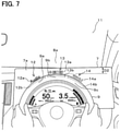
By performing the above-described process, the controller 2 controls the display position of the display information as described below. As shown in FIG. 3, when the position of the face of the driver is lowered from the state where the display information 12 to 14 is displayed, and the visual line position of the driver is lowered, the visible range of the driver from the upper end of the display area 7 a of the meter display 7 to the upper end of the steering wheel 9 becomes narrower in the vertical direction (i.e., “D1” in FIG. 3>“D2” in FIGS. 7 and 8). Therefore, when the driver's visual line position is lowered, and if the display mode shown in FIG. 3 is maintained, a part of the display information 12 to 14 is hidden behind the steering wheel 9 as shown in FIG. 7.
In contrast, in the present embodiment, when the controller 2 determines that the visual line position of the driver is lowered, and determines that the display information is hidden behind the steering wheel 9 as seen from the visual line position of the driver, the controller 2 calculates the display position which is not hidden behind the steering wheel 9 as seen from the visual line position of the driver. Then, as shown in FIG. 8, the controller 2 displays the display information 12 to 14 at the calculated display position, and changes the display position of the display information 12 to 14, thereby avoiding a situation where a part of the display information 12 to 14 is hidden behind the steering wheel 9. In FIG. 8, the controller 2 determines that all of the display information 12 to 14 can be displayed only in the display area 7 a of the meter display 7, and displays the display information 12 to 14 only on the meter display 7.
When the visual line position of the driver is further lowered, the visible range of the driver from the upper end of the display area 7 a of the meter display 7 to the upper end of the steering wheel 9 becomes further narrower in the vertical direction (that is, “D2” in FIGS. 7 and 8>“D3” in FIG. 9). Also in this case, when the controller 2 determines that the visual line position of the driver is further lowered, and determines that the display information 12 to 14 is hidden behind the steering wheel 9 as seen from the visual line position of the driver, the controller 2 calculates the display position which is not hidden behind the steering wheel 9 as seen from the visual line position of the driver. Then, as shown in FIG. 9, the controller 2 displays the display information 12 to 14 at the calculated display position, and changes the display position of the display information 12 to 14, thereby avoiding a situation where a part of the display information 12 to 14 is hidden behind the steering wheel 9. In FIG. 9, the controller 2 determines that all of the display information 12 to 14 can not be displayed only in the display area 7 a of the meter display 7, and displays the display information 12 to 14 on a part of the meter display 7 and a part of the head-up display 8.
In the above description, the case where the display information 12 to 14 is simultaneously displayed has been described. Similarly, as shown in FIG. 4, when display information 15 to 17 related to various settings of the audio apparatus is displayed at the same time, and, as shown in FIG. 5, and when the display information 18 to 20 related to various settings of the air-conditioner is simultaneously displayed, the above features are applied. Similarly, when two or less pieces of display information are simultaneously displayed, and when four or more pieces of display information are simultaneously displayed, the above features are applied.
Further, the controller 2 may return the display position of the display information to the position before the visual line position of the driver is lowered, when the visual line position of the driver is raised after the visual line position is lowered, and the visual line position of the driver returns to the position before the visual line position is lowered. That is, as shown in FIG. 9, when the position of the face of the driver is raised from the state where the display information 12 to 14 is displayed, and the visual line position of the driver is raised (that is, returned), the visible range of the driver from the upper end of the display area 7 a of the meter display 7 to the upper end of the steering wheel 9 widens in the vertical direction. In this case, if the display position of the display information 12 to 14 is left unsolved, the divergence between the display information 12 to 14 and the upper end of the steering wheel 9 becomes relatively large, and there is a possibility that the driver feels discomfort. Thus, the display position of the display information 12 to 14 is returned to the position before the visual line position of the driver is lowered, thereby avoiding a situation that the driver feels discomfort. That is, when the controller 2 determines that the display information is not hidden behind the steering wheel 9 as seen from the visual line position of the driver (NO at S3), the controller 2 determines the distance from the upper end of the steering wheel 9 to the display information 12 to 14. When the controller 2 determines that the distance is equal to or greater than the predetermined distance preliminarily set in advance, the controller 2 determines that the deviation between the display information 12 to 14 and the upper end of the steering wheel 9 is relatively large, and the controller 2 may control to change the display position of the display information 12 to 14 so as to reduce the deviation to be relatively small.
The configuration described in the present embodiment can provide advantages below.
In the vehicle operation system 1, a display position not hidden behind the steering wheel 9 is calculated using the calculation result of calculating the visual line position of the driver and the position coordinate of the steering wheel 9, and the display information indicating the content of the operation on the steering wheel 9 is displayed at the display position. Even when the posture of the driver changes, the driver can properly view and recognize the display information indicating the content of the operation on the steering wheel 9, thereby improving the convenience. That is, the driver can visually recognize a plurality of options appropriately, and can appropriately perform an operation of selecting one of a plurality of options.
When it is determined that all of the display information can be displayed only in the display area 7 a of the meter display 7, the display information is displayed only on the meter display 7. On the other hand, when all of the display information is not displayed only in the display area 7 a of the meter display 7, the display information is displayed on a part of the meter display 7 and a part of the head up display 8. When the degree of lowering the visual line position of the driver is relatively small, the display information is displayed only on the meter display 7. When the degree of lowering the visual line position of the driver is relatively large, the display information is displayed on a part of the meter display 7 and a part of the head up display 8. Thus, it is possible to flexibly respond to the degree of lowering the visual line position of the driver.
Although the present disclosure has been described in accordance with the embodiments, it is understood that the present disclosure is not limited to the embodiments and structures. The present disclosure may cover various modification examples and equivalent arrangements. Furthermore, various combinations and formations, and other combinations and formations including one, more than one or less than one element may be included in the scope and the spirit of the present disclosure.
A case where a plurality of pieces of display information indicating hierarchical options are displayed in a display manner along the shape of the steering wheel 9 has been exemplified as the display information showing the content of the operation on the steering wheel. For example, it may be applied to the case where the display information indicated by the slide bar on the level of the temperature in the air conditioner or the magnitude of the sound volume in the audio device is displayed in the display mode conforming to the shape of the steering wheel 9. According to such a configuration, the driver can properly visually recognize the magnitude of the sound volume and the level of the temperature, and for example, by sliding the palm along the shape of the steering wheel 9, the driver can properly perform the adjustment operation to control the magnitude of the volume and the level of the temperature.
Although an audio device or an air conditioner device is exemplified as a control target device, a device or a unit etc. connected via an in-vehicle network such as CAN (Controller Area Network) (registered trademark) or MOST (Media Oriented Systems Transport) (registered trademark) may be adopted. That is, for example, an advanced driving support system unit having a lane keep function or the like, an autonomous driving system unit having an automatic accelerator control function, an automatic brake control function or the like may be adopted as a control target device. In addition, as a control target device, an on-vehicle telephone fixedly installed in a vehicle, a simplified mobile phone capable of being brought into a passenger compartment for a driver, or a multifunctional mobile phone defined as a smartphone may be adopted. In case of a cellular phone that can be brought into the passenger compartment for the driver, for example, the cellular phone is connected to the controller 2 via Bluetooth (registered trademark), thereby inputting various signals from the controller 2, and performing various controls.

Claims (5)

The invention claimed is:
1. A vehicle operation system for controlling a control target device by performing a predetermined operation of a driver on a steering wheel of a vehicle, the vehicle operation system comprising a processor and memory configured to:
calculate a visual line position of the driver;
determine a viewable display area of a meter display that is not hidden behind the steering wheel based on the visual line position of the driver and a position coordinate of the steering wheel, the meter display being positioned on a far side of the steering wheel between the steering wheel and a dashboard of the vehicle and configured to display information corresponding to the predetermined operation of the driver on the steering wheel of the vehicle, and the viewable display area being located between an upper end of the steering wheel and an upper end of the meter display;
determine whether the viewable display area of the meter display is large enough to display all of the display information corresponding to the predetermined operation of the driver on the steering wheel of the vehicle;
display all of the display information on only the viewable display area of the meter display in response to determining that the viewable display area of the meter display is large enough to display all of the display information corresponding to the predetermined operation of the driver on the steering wheel of the vehicle; and
display a first potion of the display information on the viewable display area of the meter display and a second portion of the display information on a head-up display of the vehicle in response to determining that the viewable display area of the meter display is not large enough to display all of the display information corresponding to the predetermined operation of the driver on the steering wheel of the vehicle.
2. The vehicle operation system according to claim 1, wherein:
the display controller displays at least a portion of the display information in a display manner in a shape corresponding to the steering wheel along the upper end of the steering wheel.
3. The vehicle operation system according to claim 1, wherein the processor and memory are further configured to:
display a plurality of pieces of the display information having different contents of the operation at a plurality of different display positions.
4. The vehicle operation system according to claim 1, wherein the processor and memory are further configured to:
recognize an image including a face of the driver photographed by an imaging unit; and
calculate a face position of the driver using a result of recognizing the image and calculate the visual line position of the driver.
5. A computer-readable non-transitory storage medium comprising instructions being executed by a computer, the instructions including a computer-implemented method for controlling a controller in a vehicle operation system, which performs a control of a control target device by performing a predetermined operation of a driver on a steering wheel of a vehicle, the instructions including:
calculating a visual line position of the driver;
determining a viewable display area of a meter display that is not hidden behind the steering wheel based on the visual line position of the driver and a position coordinate of the steering wheel, the meter display being positioned on a far side of the steering wheel between the steering wheel and a dashboard of the vehicle and configured to display information corresponding to the predetermined operation of the driver on the steering wheel of the vehicle, and the viewable display area being located between an upper end of the steering wheel and an upper end of the meter display;
determining whether the viewable display area of the meter display is large enough to display all of the display information corresponding to the predetermined operation of the driver on the steering wheel of the vehicle;
displaying all of the display information on only the viewable display area of the meter display in response to determining that the viewable display area of the meter display is large enough to display all of the display information corresponding to the predetermined operation of the driver on the steering wheel of the vehicle;
displaying a first potion of the display information on the viewable display area of the meter display and a second portion of the display information on a head-up display of the vehicle in response to determining that the viewable display area of the meter display is not large enough to display all of the display information corresponding to the predetermined operation of the driver on the steering wheel of the vehicle.
US16/325,598 2016-09-01 2017-06-29 Vehicle operation system and computer readable non-transitory storage medium Active 2038-10-29 US11276378B2 (en)

Applications Claiming Priority (4)

Application Number Priority Date Filing Date Title
JP2016170813A JP6669017B2 (en) 2016-09-01 2016-09-01 Vehicle operation system and computer program
JPJP2016-170813 2016-09-01
JP2016-170813 2016-09-01
PCT/JP2017/023968 WO2018042861A1 (en) 2016-09-01 2017-06-29 Vehicle operation system and computer program

Publications (2)

Publication Number Publication Date
US20210280157A1 US20210280157A1 (en) 2021-09-09
US11276378B2 true US11276378B2 (en) 2022-03-15

Family

ID=61300680

Family Applications (1)

Application Number Title Priority Date Filing Date
US16/325,598 Active 2038-10-29 US11276378B2 (en) 2016-09-01 2017-06-29 Vehicle operation system and computer readable non-transitory storage medium

Country Status (5)

Country Link
US (1) US11276378B2 (en)
JP (1) JP6669017B2 (en)
CN (1) CN109661702A (en)
DE (1) DE112017004385T5 (en)
WO (1) WO2018042861A1 (en)

Cited By (1)

* Cited by examiner, † Cited by third party
Publication number Priority date Publication date Assignee Title
US20220147301A1 (en) * 2019-03-11 2022-05-12 Panasonic Intellectual Property Management Co., Ltd. Display control device, display system, display control method, program

Families Citing this family (2)

* Cited by examiner, † Cited by third party
Publication number Priority date Publication date Assignee Title
JP7081901B2 (en) * 2016-10-21 2022-06-07 株式会社デンソーテン Display control device and display control method
JP7207251B2 (en) * 2019-10-09 2023-01-18 株式会社デンソー vehicle display

Citations (10)

* Cited by examiner, † Cited by third party
Publication number Priority date Publication date Assignee Title
US20050154505A1 (en) * 2003-12-17 2005-07-14 Koji Nakamura Vehicle information display system
JP2008162550A (en) 2007-01-04 2008-07-17 Toyota Motor Corp External environment display device
US20140125583A1 (en) * 2012-11-08 2014-05-08 Honda Motor Co., Ltd. Vehicular display system
US20140156107A1 (en) * 2011-08-11 2014-06-05 JVC Kenwood Corporation Control apparatus and method for controlling operation target device in vehicle, and steering wheel
WO2015037325A1 (en) 2013-09-12 2015-03-19 株式会社デンソー Vehicle-mounted display device
JP2015168264A (en) 2014-03-04 2015-09-28 株式会社デンソー display device
JP5909048B2 (en) 2011-03-31 2016-04-26 本田技研工業株式会社 In-vehicle input device
US20160132126A1 (en) * 2014-11-07 2016-05-12 Alexander van Laack System for information transmission in a motor vehicle
US20160173568A1 (en) * 2011-04-22 2016-06-16 Angel A. Penilla Methods and Systems for Processing User Inputs to Generate Recommended Vehicle Settings and Associated Vehicle-Cloud Communication
US20160323722A1 (en) * 2014-11-12 2016-11-03 Katherine Rose Kovarik Method and System for Improving the Safety of Driving While Communicating

Family Cites Families (13)

* Cited by examiner, † Cited by third party
Publication number Priority date Publication date Assignee Title
JPS6390446A (en) * 1986-10-06 1988-04-21 Mazda Motor Corp Meter display device for automobile
JPH11314538A (en) * 1998-05-01 1999-11-16 Nissan Motor Co Ltd Vehicular display system
JP4757091B2 (en) * 2006-04-28 2011-08-24 本田技研工業株式会社 Operation device for on-vehicle equipment
JP5150106B2 (en) * 2006-06-05 2013-02-20 本田技研工業株式会社 Visual assist device for vehicles
JP2010202058A (en) * 2009-03-04 2010-09-16 Denso Corp On-vehicle display device
DE102010013241A1 (en) * 2010-03-29 2011-09-29 Audi Ag Device for displaying information in a motor vehicle
DE102010046124A1 (en) * 2010-09-21 2012-03-22 Gm Global Technology Operations Llc (N.D.Ges.D. Staates Delaware) Information display arrangement
JP5935655B2 (en) * 2012-10-24 2016-06-15 株式会社デンソー Information display device
US9120379B2 (en) * 2013-09-25 2015-09-01 Denso International America, Inc. Adaptive instrument display using eye tracking
JP6026011B2 (en) * 2013-11-15 2016-11-16 三菱電機株式会社 Display control apparatus, information display method, and information display system
JP6314067B2 (en) * 2014-09-12 2018-04-18 矢崎総業株式会社 In-vehicle display device
US9463694B1 (en) * 2015-05-06 2016-10-11 Ford Global Techologies, Llc Vehicle instrument cluster
JP6302004B2 (en) 2016-06-16 2018-03-28 日立オートモティブシステムズ株式会社 Writing program

Patent Citations (11)

* Cited by examiner, † Cited by third party
Publication number Priority date Publication date Assignee Title
US20050154505A1 (en) * 2003-12-17 2005-07-14 Koji Nakamura Vehicle information display system
JP2008162550A (en) 2007-01-04 2008-07-17 Toyota Motor Corp External environment display device
JP5909048B2 (en) 2011-03-31 2016-04-26 本田技研工業株式会社 In-vehicle input device
US20160173568A1 (en) * 2011-04-22 2016-06-16 Angel A. Penilla Methods and Systems for Processing User Inputs to Generate Recommended Vehicle Settings and Associated Vehicle-Cloud Communication
US20140156107A1 (en) * 2011-08-11 2014-06-05 JVC Kenwood Corporation Control apparatus and method for controlling operation target device in vehicle, and steering wheel
US20140125583A1 (en) * 2012-11-08 2014-05-08 Honda Motor Co., Ltd. Vehicular display system
JP2014094647A (en) 2012-11-08 2014-05-22 Honda Motor Co Ltd Vehicle display device
WO2015037325A1 (en) 2013-09-12 2015-03-19 株式会社デンソー Vehicle-mounted display device
JP2015168264A (en) 2014-03-04 2015-09-28 株式会社デンソー display device
US20160132126A1 (en) * 2014-11-07 2016-05-12 Alexander van Laack System for information transmission in a motor vehicle
US20160323722A1 (en) * 2014-11-12 2016-11-03 Katherine Rose Kovarik Method and System for Improving the Safety of Driving While Communicating

Cited By (2)

* Cited by examiner, † Cited by third party
Publication number Priority date Publication date Assignee Title
US20220147301A1 (en) * 2019-03-11 2022-05-12 Panasonic Intellectual Property Management Co., Ltd. Display control device, display system, display control method, program
US11768650B2 (en) * 2019-03-11 2023-09-26 Panasonic Intellectual Property Management Co., Ltd. Display control device, display system, and display control method for controlling display of information

Also Published As

Publication number Publication date
CN109661702A (en) 2019-04-19
JP6669017B2 (en) 2020-03-18
US20210280157A1 (en) 2021-09-09
WO2018042861A1 (en) 2018-03-08
DE112017004385T5 (en) 2019-05-16
JP2018034716A (en) 2018-03-08

Similar Documents

Publication Publication Date Title
US9360668B2 (en) Dynamically calibrated head-up display
US10304228B2 (en) Vehicular display apparatus and vehicular display method
US8947533B2 (en) Parameter determining device, parameter determining system, parameter determining method, and recording medium
US20170269684A1 (en) Vehicle display device
US9430046B2 (en) Gesture based image capturing system for vehicle
US9517776B2 (en) Systems, methods, and apparatus for controlling devices based on a detected gaze
US8874321B2 (en) Display control apparatus for vehicle
US9463743B2 (en) Vehicle information display device and vehicle information display method
CN111038402A (en) Apparatus and method for controlling display of vehicle
WO2019008764A1 (en) Parking assistance method and parking assistance device
US11276378B2 (en) Vehicle operation system and computer readable non-transitory storage medium
JP2010018201A (en) Driver assistant device, driver assistant method, and driver assistant processing program
RU2720591C1 (en) Information displaying method and display control device
JP2013168063A (en) Image processing device, image display system, and image processing method
US20190236343A1 (en) Gesture detection device
US20180166047A1 (en) Electronic control device
US11562576B2 (en) Dynamic adjustment of augmented reality image
JP2014120114A (en) Travel support system, travel support method, and computer program
KR20180021822A (en) Rear Cross Traffic - QuickLux
CN113165510A (en) Display control apparatus, method and computer program
JP3932127B2 (en) Image display device for vehicle
CN111788088A (en) Display control device and display control method for vehicle
US20200231099A1 (en) Image processing apparatus
JP2017083308A (en) Electronic apparatus, facility specification method, and facility specification program
JP3864418B2 (en) Image display device for vehicle

Legal Events

Date Code Title Description
AS Assignment

Owner name: DENSO CORPORATION, JAPAN

Free format text: ASSIGNMENT OF ASSIGNORS INTEREST;ASSIGNORS:MIZUNO, WATARU;TSUCHIKAWA, KAZUTOMO;SUZUKI, DAISUKE;AND OTHERS;SIGNING DATES FROM 20180918 TO 20180921;REEL/FRAME:048336/0443

FEPP Fee payment procedure

Free format text: ENTITY STATUS SET TO UNDISCOUNTED (ORIGINAL EVENT CODE: BIG.); ENTITY STATUS OF PATENT OWNER: LARGE ENTITY

STPP Information on status: patent application and granting procedure in general

Free format text: NON FINAL ACTION MAILED

STPP Information on status: patent application and granting procedure in general

Free format text: RESPONSE TO NON-FINAL OFFICE ACTION ENTERED AND FORWARDED TO EXAMINER

STPP Information on status: patent application and granting procedure in general

Free format text: NOTICE OF ALLOWANCE MAILED -- APPLICATION RECEIVED IN OFFICE OF PUBLICATIONS

STCF Information on status: patent grant

Free format text: PATENTED CASE