US11225029B2 - Device for producing three-dimensional models and methods thereof - Google Patents
Device for producing three-dimensional models and methods thereof Download PDFInfo
- Publication number
- US11225029B2 US11225029B2 US16/245,831 US201916245831A US11225029B2 US 11225029 B2 US11225029 B2 US 11225029B2 US 201916245831 A US201916245831 A US 201916245831A US 11225029 B2 US11225029 B2 US 11225029B2
- Authority
- US
- United States
- Prior art keywords
- tunnel
- feedstock
- conveyor
- particulate material
- coater
- Prior art date
- Legal status (The legal status is an assumption and is not a legal conclusion. Google has not performed a legal analysis and makes no representation as to the accuracy of the status listed.)
- Active, expires
Links
- 238000000034 method Methods 0.000 title claims abstract description 64
- 239000011236 particulate material Substances 0.000 claims description 53
- 239000000463 material Substances 0.000 claims description 33
- 238000012546 transfer Methods 0.000 claims description 8
- 239000000843 powder Substances 0.000 claims description 2
- 238000007711 solidification Methods 0.000 abstract description 19
- 230000008023 solidification Effects 0.000 abstract description 19
- 238000010924 continuous production Methods 0.000 abstract description 9
- 230000008569 process Effects 0.000 description 20
- 238000004519 manufacturing process Methods 0.000 description 10
- 239000011888 foil Substances 0.000 description 6
- 230000007246 mechanism Effects 0.000 description 6
- 230000000694 effects Effects 0.000 description 5
- 230000008901 benefit Effects 0.000 description 4
- 238000013461 design Methods 0.000 description 4
- 238000007665 sagging Methods 0.000 description 4
- 239000000126 substance Substances 0.000 description 4
- 238000010146 3D printing Methods 0.000 description 3
- 238000007789 sealing Methods 0.000 description 3
- 238000013459 approach Methods 0.000 description 2
- 238000010276 construction Methods 0.000 description 2
- 239000000356 contaminant Substances 0.000 description 2
- 238000011437 continuous method Methods 0.000 description 2
- 230000007547 defect Effects 0.000 description 2
- 230000001419 dependent effect Effects 0.000 description 2
- 239000004033 plastic Substances 0.000 description 2
- 229920003023 plastic Polymers 0.000 description 2
- 238000003825 pressing Methods 0.000 description 2
- 238000007639 printing Methods 0.000 description 2
- 238000004804 winding Methods 0.000 description 2
- CWYNVVGOOAEACU-UHFFFAOYSA-N Fe2+ Chemical compound [Fe+2] CWYNVVGOOAEACU-UHFFFAOYSA-N 0.000 description 1
- 239000000853 adhesive Substances 0.000 description 1
- 230000001070 adhesive effect Effects 0.000 description 1
- 238000000149 argon plasma sintering Methods 0.000 description 1
- 239000011230 binding agent Substances 0.000 description 1
- 238000005266 casting Methods 0.000 description 1
- 230000008859 change Effects 0.000 description 1
- 238000011109 contamination Methods 0.000 description 1
- 230000008878 coupling Effects 0.000 description 1
- 238000010168 coupling process Methods 0.000 description 1
- 238000005859 coupling reaction Methods 0.000 description 1
- 230000008021 deposition Effects 0.000 description 1
- 230000005484 gravity Effects 0.000 description 1
- 229910001385 heavy metal Inorganic materials 0.000 description 1
- 230000002706 hydrostatic effect Effects 0.000 description 1
- 238000012423 maintenance Methods 0.000 description 1
- 230000008018 melting Effects 0.000 description 1
- 238000002844 melting Methods 0.000 description 1
- 239000003110 molding sand Substances 0.000 description 1
- 238000000465 moulding Methods 0.000 description 1
- 239000002245 particle Substances 0.000 description 1
- 230000000284 resting effect Effects 0.000 description 1
- 230000002441 reversible effect Effects 0.000 description 1
- 238000005096 rolling process Methods 0.000 description 1
- 239000004576 sand Substances 0.000 description 1
- 238000000110 selective laser sintering Methods 0.000 description 1
- 239000007787 solid Substances 0.000 description 1
- 239000002904 solvent Substances 0.000 description 1
- 230000003068 static effect Effects 0.000 description 1
- 230000001360 synchronised effect Effects 0.000 description 1
- 239000002759 woven fabric Substances 0.000 description 1
Images


Classifications
-
- B—PERFORMING OPERATIONS; TRANSPORTING
- B29—WORKING OF PLASTICS; WORKING OF SUBSTANCES IN A PLASTIC STATE IN GENERAL
- B29C—SHAPING OR JOINING OF PLASTICS; SHAPING OF MATERIAL IN A PLASTIC STATE, NOT OTHERWISE PROVIDED FOR; AFTER-TREATMENT OF THE SHAPED PRODUCTS, e.g. REPAIRING
- B29C64/00—Additive manufacturing, i.e. manufacturing of three-dimensional [3D] objects by additive deposition, additive agglomeration or additive layering, e.g. by 3D printing, stereolithography or selective laser sintering
- B29C64/10—Processes of additive manufacturing
- B29C64/141—Processes of additive manufacturing using only solid materials
- B29C64/153—Processes of additive manufacturing using only solid materials using layers of powder being selectively joined, e.g. by selective laser sintering or melting
-
- B—PERFORMING OPERATIONS; TRANSPORTING
- B22—CASTING; POWDER METALLURGY
- B22F—WORKING METALLIC POWDER; MANUFACTURE OF ARTICLES FROM METALLIC POWDER; MAKING METALLIC POWDER; APPARATUS OR DEVICES SPECIALLY ADAPTED FOR METALLIC POWDER
- B22F10/00—Additive manufacturing of workpieces or articles from metallic powder
- B22F10/10—Formation of a green body
-
- B—PERFORMING OPERATIONS; TRANSPORTING
- B22—CASTING; POWDER METALLURGY
- B22F—WORKING METALLIC POWDER; MANUFACTURE OF ARTICLES FROM METALLIC POWDER; MAKING METALLIC POWDER; APPARATUS OR DEVICES SPECIALLY ADAPTED FOR METALLIC POWDER
- B22F10/00—Additive manufacturing of workpieces or articles from metallic powder
- B22F10/80—Data acquisition or data processing
- B22F10/85—Data acquisition or data processing for controlling or regulating additive manufacturing processes
-
- B—PERFORMING OPERATIONS; TRANSPORTING
- B22—CASTING; POWDER METALLURGY
- B22F—WORKING METALLIC POWDER; MANUFACTURE OF ARTICLES FROM METALLIC POWDER; MAKING METALLIC POWDER; APPARATUS OR DEVICES SPECIALLY ADAPTED FOR METALLIC POWDER
- B22F12/00—Apparatus or devices specially adapted for additive manufacturing; Auxiliary means for additive manufacturing; Combinations of additive manufacturing apparatus or devices with other processing apparatus or devices
- B22F12/30—Platforms or substrates
- B22F12/33—Platforms or substrates translatory in the deposition plane
-
- B—PERFORMING OPERATIONS; TRANSPORTING
- B22—CASTING; POWDER METALLURGY
- B22F—WORKING METALLIC POWDER; MANUFACTURE OF ARTICLES FROM METALLIC POWDER; MAKING METALLIC POWDER; APPARATUS OR DEVICES SPECIALLY ADAPTED FOR METALLIC POWDER
- B22F12/00—Apparatus or devices specially adapted for additive manufacturing; Auxiliary means for additive manufacturing; Combinations of additive manufacturing apparatus or devices with other processing apparatus or devices
- B22F12/50—Means for feeding of material, e.g. heads
-
- B—PERFORMING OPERATIONS; TRANSPORTING
- B29—WORKING OF PLASTICS; WORKING OF SUBSTANCES IN A PLASTIC STATE IN GENERAL
- B29C—SHAPING OR JOINING OF PLASTICS; SHAPING OF MATERIAL IN A PLASTIC STATE, NOT OTHERWISE PROVIDED FOR; AFTER-TREATMENT OF THE SHAPED PRODUCTS, e.g. REPAIRING
- B29C64/00—Additive manufacturing, i.e. manufacturing of three-dimensional [3D] objects by additive deposition, additive agglomeration or additive layering, e.g. by 3D printing, stereolithography or selective laser sintering
- B29C64/10—Processes of additive manufacturing
- B29C64/141—Processes of additive manufacturing using only solid materials
-
- B—PERFORMING OPERATIONS; TRANSPORTING
- B29—WORKING OF PLASTICS; WORKING OF SUBSTANCES IN A PLASTIC STATE IN GENERAL
- B29C—SHAPING OR JOINING OF PLASTICS; SHAPING OF MATERIAL IN A PLASTIC STATE, NOT OTHERWISE PROVIDED FOR; AFTER-TREATMENT OF THE SHAPED PRODUCTS, e.g. REPAIRING
- B29C64/00—Additive manufacturing, i.e. manufacturing of three-dimensional [3D] objects by additive deposition, additive agglomeration or additive layering, e.g. by 3D printing, stereolithography or selective laser sintering
- B29C64/10—Processes of additive manufacturing
- B29C64/171—Processes of additive manufacturing specially adapted for manufacturing multiple 3D objects
- B29C64/176—Sequentially
-
- B—PERFORMING OPERATIONS; TRANSPORTING
- B29—WORKING OF PLASTICS; WORKING OF SUBSTANCES IN A PLASTIC STATE IN GENERAL
- B29C—SHAPING OR JOINING OF PLASTICS; SHAPING OF MATERIAL IN A PLASTIC STATE, NOT OTHERWISE PROVIDED FOR; AFTER-TREATMENT OF THE SHAPED PRODUCTS, e.g. REPAIRING
- B29C64/00—Additive manufacturing, i.e. manufacturing of three-dimensional [3D] objects by additive deposition, additive agglomeration or additive layering, e.g. by 3D printing, stereolithography or selective laser sintering
- B29C64/20—Apparatus for additive manufacturing; Details thereof or accessories therefor
- B29C64/245—Platforms or substrates
-
- B—PERFORMING OPERATIONS; TRANSPORTING
- B29—WORKING OF PLASTICS; WORKING OF SUBSTANCES IN A PLASTIC STATE IN GENERAL
- B29C—SHAPING OR JOINING OF PLASTICS; SHAPING OF MATERIAL IN A PLASTIC STATE, NOT OTHERWISE PROVIDED FOR; AFTER-TREATMENT OF THE SHAPED PRODUCTS, e.g. REPAIRING
- B29C64/00—Additive manufacturing, i.e. manufacturing of three-dimensional [3D] objects by additive deposition, additive agglomeration or additive layering, e.g. by 3D printing, stereolithography or selective laser sintering
- B29C64/40—Structures for supporting 3D objects during manufacture and intended to be sacrificed after completion thereof
-
- B—PERFORMING OPERATIONS; TRANSPORTING
- B22—CASTING; POWDER METALLURGY
- B22F—WORKING METALLIC POWDER; MANUFACTURE OF ARTICLES FROM METALLIC POWDER; MAKING METALLIC POWDER; APPARATUS OR DEVICES SPECIALLY ADAPTED FOR METALLIC POWDER
- B22F10/00—Additive manufacturing of workpieces or articles from metallic powder
- B22F10/20—Direct sintering or melting
- B22F10/28—Powder bed fusion, e.g. selective laser melting [SLM] or electron beam melting [EBM]
-
- B—PERFORMING OPERATIONS; TRANSPORTING
- B22—CASTING; POWDER METALLURGY
- B22F—WORKING METALLIC POWDER; MANUFACTURE OF ARTICLES FROM METALLIC POWDER; MAKING METALLIC POWDER; APPARATUS OR DEVICES SPECIALLY ADAPTED FOR METALLIC POWDER
- B22F12/00—Apparatus or devices specially adapted for additive manufacturing; Auxiliary means for additive manufacturing; Combinations of additive manufacturing apparatus or devices with other processing apparatus or devices
- B22F12/22—Driving means
- B22F12/226—Driving means for rotary motion
-
- B—PERFORMING OPERATIONS; TRANSPORTING
- B22—CASTING; POWDER METALLURGY
- B22F—WORKING METALLIC POWDER; MANUFACTURE OF ARTICLES FROM METALLIC POWDER; MAKING METALLIC POWDER; APPARATUS OR DEVICES SPECIALLY ADAPTED FOR METALLIC POWDER
- B22F12/00—Apparatus or devices specially adapted for additive manufacturing; Auxiliary means for additive manufacturing; Combinations of additive manufacturing apparatus or devices with other processing apparatus or devices
- B22F12/30—Platforms or substrates
- B22F12/37—Rotatable
-
- B—PERFORMING OPERATIONS; TRANSPORTING
- B29—WORKING OF PLASTICS; WORKING OF SUBSTANCES IN A PLASTIC STATE IN GENERAL
- B29K—INDEXING SCHEME ASSOCIATED WITH SUBCLASSES B29B, B29C OR B29D, RELATING TO MOULDING MATERIALS OR TO MATERIALS FOR MOULDS, REINFORCEMENTS, FILLERS OR PREFORMED PARTS, e.g. INSERTS
- B29K2103/00—Use of resin-bonded materials as moulding material
-
- B—PERFORMING OPERATIONS; TRANSPORTING
- B29—WORKING OF PLASTICS; WORKING OF SUBSTANCES IN A PLASTIC STATE IN GENERAL
- B29K—INDEXING SCHEME ASSOCIATED WITH SUBCLASSES B29B, B29C OR B29D, RELATING TO MOULDING MATERIALS OR TO MATERIALS FOR MOULDS, REINFORCEMENTS, FILLERS OR PREFORMED PARTS, e.g. INSERTS
- B29K2105/00—Condition, form or state of moulded material or of the material to be shaped
- B29K2105/25—Solid
- B29K2105/251—Particles, powder or granules
-
- B—PERFORMING OPERATIONS; TRANSPORTING
- B33—ADDITIVE MANUFACTURING TECHNOLOGY
- B33Y—ADDITIVE MANUFACTURING, i.e. MANUFACTURING OF THREE-DIMENSIONAL [3-D] OBJECTS BY ADDITIVE DEPOSITION, ADDITIVE AGGLOMERATION OR ADDITIVE LAYERING, e.g. BY 3-D PRINTING, STEREOLITHOGRAPHY OR SELECTIVE LASER SINTERING
- B33Y10/00—Processes of additive manufacturing
-
- B—PERFORMING OPERATIONS; TRANSPORTING
- B33—ADDITIVE MANUFACTURING TECHNOLOGY
- B33Y—ADDITIVE MANUFACTURING, i.e. MANUFACTURING OF THREE-DIMENSIONAL [3-D] OBJECTS BY ADDITIVE DEPOSITION, ADDITIVE AGGLOMERATION OR ADDITIVE LAYERING, e.g. BY 3-D PRINTING, STEREOLITHOGRAPHY OR SELECTIVE LASER SINTERING
- B33Y30/00—Apparatus for additive manufacturing; Details thereof or accessories therefor
-
- Y—GENERAL TAGGING OF NEW TECHNOLOGICAL DEVELOPMENTS; GENERAL TAGGING OF CROSS-SECTIONAL TECHNOLOGIES SPANNING OVER SEVERAL SECTIONS OF THE IPC; TECHNICAL SUBJECTS COVERED BY FORMER USPC CROSS-REFERENCE ART COLLECTIONS [XRACs] AND DIGESTS
- Y02—TECHNOLOGIES OR APPLICATIONS FOR MITIGATION OR ADAPTATION AGAINST CLIMATE CHANGE
- Y02P—CLIMATE CHANGE MITIGATION TECHNOLOGIES IN THE PRODUCTION OR PROCESSING OF GOODS
- Y02P10/00—Technologies related to metal processing
- Y02P10/25—Process efficiency
Definitions
- the present invention relates to a system for the continuous production of three-dimensional models on a horizontal transport device, using a layering technique.
- a platform which is movable at least in the vertical direction and which, if necessary, is surrounded by a container and thus forms a job box, is placed in an uppermost position at the beginning of the process.
- a build material for example a substance in the form of particulate material in the case of 3D printing or laser sintering, is then applied in a thin layer over the entire area of this platform.
- the material is selectively bound with the aid of a physical or chemical solidification mechanism according to the desired component shape. This binding step may take place, for example, using adhesives, which may be printed with the aid of ink jet techniques.
- the platform is then lowered by one layer thickness, and a new layer of particulate material is applied.
- the container is successively filled with particulate material during these steps, parts thereof being bound to the desired structural body, while the rest remains loose and is used during the building process as a support medium for overhanging parts of the object to be built.
- the loose particulate material may be extracted or removed in another manner and the desired object discharged.
- the components are produced vertically in layers from top to bottom.
- the building process When the maximum build height of a system is reached, the building process must be stopped in order to subsequently remove the components in the system and thereby create space for a building process, or another build frame must be inserted with the aid of a changing system in order to be able to thereby start a new building process. As a result, the construction of components is limited with respect to size and productivity.
- the layer feed takes place in the horizontal direction, e.g., on a continuous conveyor belt.
- Gravity prevents a layer to be applied perpendicularly to the layer feed, which is why the individual layers are applied at an angle.
- the angle is selected in such a way that it is smaller than the specific angle of repose of the corresponding particulate material.
- the layering process is followed by an enclosed conveyor line, whose length is adapted to the method-dependent hardening duration.
- the finished components enter a removal area. There, the components are freed of unbound particle material and removed without having to interrupt the production of additional parts.
- Continuous conveyor belts are generally closed belts made of a flexible material (e.g., woven fabric) that is looped around a drum at each end to reverse the direction of travel. At least one of the two drums drives the conveyor belt. Between the drums, the belt must be pulled over a supporting surface to avoid sagging. Above a certain width of the conveyor belt or above a certain mass of the particulate material feedstock, the frictional engagement between the conveyor belt and the supporting surface is so great that stick/slip effects may occur, or the drive may fail completely.
- a flexible material e.g., woven fabric
- Link conveyors are furthermore known, which are able to accommodate very high loads.
- Link conveyors of this type are driven in the same way as conveyor belts.
- a drive drum or return drum is located at each end of the closed link conveyor. If a link conveyor is driven in this manner, an uneven feed results. This is because the plates unwind in the manner of a polygon.
- the bearing of the individual links may prove to be sensitive to contaminants. If the links do not ideally abut each other, build material may enter the space between two plates via the joints and impair the operation of the flexible connection. In addition, particulate material may be lost uncontrollably via the joint, which may result in defects in the particulate material feedstock and thus in the components.
- Link conveyors are an additional option.
- Link conveyors are able to accommodate high loads and are driven in the same manner as conveyor belts.
- a drive drum or return drum is located at each end of the closed link conveyor. If a link conveyor is driven in this manner, an uneven feed results. This is because the plates unwind in the manner of a polygon.
- the bearing of the individual links may prove to be sensitive to contaminants. If the links do not ideally abut each other, build material may enter the space between two plates via the joints and impair the operation of the flexible connection. In addition, particulate material may be lost uncontrollably via the joint, which may result in defects in the particulate material feedstock and thus in the components.
- the invention relates to a device for producing three-dimensional models, preferably in a continuous process, comprising a build surface which has a first end in the direction of movement and a second end in the direction of movement, at least one dosing device and at least one solidification unit, characterized in that the build surface is designed to transport heavy components, and the components are transportable over the build surface essentially without distortion.
- the first end is understood to be the start of the process
- the second end is understood to be the end of the process, or preferably the unpacking position or the unpacking operation.
- the inventors have advantageously succeeded in providing drives which are suitable for producing bulky and heavy components, in particular in continuous processes, for building models in layers using inclined printing, and which facilitate precise production without distortion in compliance with the requirements.
- the inventors thus have developed a device and a method, by means of which particularly heavy components may be precisely produced in the continuous layering method (inclined printing) and which avoid or at least significantly improve the disadvantages of the prior art.
- the work takes place in batches.
- the build surface is a horizontal, continuous and/or open conveyor belt, or it is designed as a rotating platform or a step conveyor.
- a particularly preferred device is characterized in that the deviation in the feed between the first and second ends of the building platform is less than 1 mm, preferably less than 0.5 mm, most preferably 0.3 mm.
- Preferred devices according to the invention may be characterized in that the conveyor belt rests and runs on continuous and/or lateral rollers.
- a device according to the invention may furthermore be characterized in that the conveyor belt has at least one central support, the support preferably comprising air cushions and/or friction bearings and/or rollers and/or ball casters.
- the conveyor belt may have individual links, preferably connected by hinges, the links having gripping elements which are driven by worm gear or guide mechanisms.
- the gripping elements may be gripped and positioned with the aid of horizontally positionable or oscillating or rotating grippers and/or barbed hooks and/or magnets and/or vacuum grippers.
- One area of the conveyor belt may be transported on a liftable base by means of frictional engagement or cohesion of solid bodies.
- the conveyor belt is preferably driven by at least one continuous roller or on both sides by at least two lateral rollers.
- one area of the conveyor belt is transported by means of magnetic fields.
- the building platforms of the device prefferably be automotively driven, preferably on overhead rails or free-moving.
- the hinges contained in the device preferably have only limited mobility perpendicularly to the conveyance direction.
- Roller tracks are preferably added to the device.
- the device according to the invention is particularly preferably characterized in that a horizontal, movable build surface for applying build material is provided, and a build space is disposed around it, on which at least one dosing device for particulate material and a solidification unit for particulate material are mounted via linear guides, and the horizontal build surface [is provided] in a Z direction, i.e., at a certain angle to the transport device which is smaller than the angle of repose of the build material.
- the angle is preferably ⁇ 30 degrees.
- FIGS. 10 a through 10 c Another aspect of the invention is a device referred to as a “cone printer” for building components. Its functionality is apparent, in particular, from FIGS. 10 a through 10 c.
- a cone printer in the sense of the invention is able to build components on a building platform in a rotating and outwardly directed motion from the inside to the outside by layering particulate material.
- the production of components takes place according to the 3D method, i.e., a layer of particulate material is applied in the first step, and a selective solidification of the particulate material takes place in the second step in the known manner.
- the application of particulate material takes place continuously, a coater ( 1 ) completing a circular path for layering the particulate material.
- the solidification unit ( 2 ) follows this path of the coater ( 1 ) and ensures the selective solidification of the particulate material and thus the production of components.
- a plurality of components may be advantageously produced on one building platform simultaneously or in batches.
- the building platform may be selected in dimensions that allow heavy components to be produced. This preferred design thus also achieves the object of a distortion-free production of multiple components.
- the special advantage of the use of a cone printer lies in the fact that large and heavy components may be produced without distortion, and a plurality of components may be produced with a high degree of precision in batches.
- the invention furthermore relates to a method for producing three dimensional models in the continuous process, comprising the following steps: a. building the model in layers on a building platform in a first position, a first layer being applied; b. transferring the model from the first position to a second position with the aid of a feed after a layer is built, the building platform, which has a first front end and a second rear end, being transported with the model; c. building another layer on the model on the building platform; d. transferring the model on the building platform to another position; repeating steps a.) through d.), the transfer preferably being carried out by means of a step conveyor, the step conveyor preferably having lifting and thrusting grates.
- the model on the building platform is transferred without distortion from the first position to the second position.
- the method according to the invention for producing three-dimensional models is characterized in that the building platform with the model is evenly transferred from the first position to the second position and any further position essentially without deviations in feed between the first and second ends of the building platform.
- the deviation in feed between the first and second ends of the building platform from the first position to the second and any further position is preferably less than 1 mm, preferably less than 0.5 mm and most preferably less than 0.3 mm.
- the requirements of the horizontal transport device of devices for the continuous method are particularly critical in order to achieve a dimensionally accurate and precise reproduction in the component.
- a loosely applied feedstock made of sand or particulate material must be positioned a few micrometers (e.g., 80 ⁇ m) with each new layer.
- the feedstock has only a limited stability and may weigh several tons.
- the present invention advantageously combines the aforementioned characteristics or at least a subcombination thereof and thus provides an advantageous device and a method for building models in layers, the disadvantages of known devices and methods being avoided or at least partially improved.
- the invention provides a superior device and method.
- the device according to the invention may be used, for example, to produce casting molds from molding sand, in which the dimensions and thus the weight of the particulate material feedstock are particularly high.
- Link conveyors whose individual links are connected by special hinges are particularly suitable in this case.
- the hinges have a stop which results in the fact that the link conveyor is able to bend or roll off from the plane in only one direction (downward in this case). It is rigid in the other direction (upward in this case). A sagging of the link conveyor is prevented thereby, and an even feed with only slight deviations or only slight distortion is achieved.
- this link apron is laid over a roller track and driven by friction engagement.
- the roller track is an arrangement of multiple rollers or cylinders. One, multiple or all rollers may be driven. If all rollers are driven, an even feed of the link conveyor results. Since the entire build space of the link conveyor is driven, the belt does not undergo any tensile loading. The belt is thus unable to lengthen during operation, and stick-slip effects are ruled out. If the link conveyor has play in the hinges, this does not have any negative effect.
- This type of drive also ensures an exact positioning, since the drive takes place at the point where the plates have already achieved a horizontal alignment.
- a polygon effect which occurs in known systems, does not take place in the invention.
- the individual rollers or cylinders may be preferably synchronized by means of coupling elements such as toothed belts, driving belts, chains, toothed wheels or worm gears. If the rollers are connected by driving belts, toothed belts or chains, the link conveyor may also rest directly on the driving belts, toothed belts or chains. Particularly wide belts require rigid cylinders or cylinders having a large diameter for support. As the cylinder diameter increases, so does the distance between the individual cylinders. Link aprons having low intrinsic rigidity could sag between the cylinders.
- each of the links it is also possible to equip each of the links with rollers or ball casters.
- the rollers may also be pressed onto the driving rollers with the aid of lateral rollers.
- the rollers may also be designed as toothed wheels.
- the individual links also have a tooth profile with which the driving wheels may engage.
- a link conveyor it is also possible to equip the underside of individual or all links with a round driving element, for example.
- the driving element is then gripped with the aid of a worm gear or a guide wheel and advanced by the necessary layer thickness.
- the individual links are equipped with a driving element, it is also possible to use a reversing linear drive, which repeatedly grips and positions the driving element by means of a gripper.
- This device may be provided with a particularly rigid design using simple means.
- a spring-supported barbed hook may also be used instead of an active gripper, similarly to a one-way bearing.
- Switchable vacuum grippers or magnets or hook-and-loop fasteners are also suitable. They may also be inserted in such a way that they engage with the belt in a rotating or oscillating manner. A preferred position would then be within the chain.
- a particularly preferred embodiment of the invention lies in the use of a discontinuous conveyor line with the aid of a step conveyor.
- the transported material is moved along the entire length in discrete steps.
- One preferred form of a conveyor mechanism of this type includes a lever system in the form of a four-bar linkage, which is driven in a rotary motion at one of the linkage points.
- a rigid supporting surface is situated on the side at a distance from the lever mechanism. The movement sequence begins with the resting position of the transported material on the supporting surface.
- a lever of the device will receive the load of the transported material, lift the transported material and place it back down on the supporting surface after a discrete distance has passed.
- the transported material must travel a horizontal distance on the supporting surface before the process starts over.
- step conveyer is to be understood as follows: a model or component is built in layers and transferred from a first position to a second position with the aid of a step conveyor device, this process continuing or being repeated in steps, and the component thus being subjected to step-by-step layering. It is possible that the process takes place in a longitudinal direction.
- the step conveyor device or the method may be designed in such a way that a repetition of the transfer from position 1 to position 2 and then back to position 1 , etc., takes place.
- the step conveyor may be used to transfer the components, which have a weight of several hundred kilograms to several hundred tons, without distortion.
- the feed of each transfer may be from several centimeters to several meters, depending on the device and the method of the layer building method.
- the feed or transfer speed may be 0.5 to 20 m/min. or 0.1 to 15 minutes per cycle.
- the step conveyor may have a fixed frame, including guide rollers, a mobile frame on lifting rollers and a drive.
- the drive may have a mechanical, pneumatic or hydraulic design for the purpose of achieving the feed or the lift. For example, the mobile frame is lowered at the start position and the building plate with the model to be constructed is lowered onto the fixed frame with the aid of, e.g., hydraulics (a first position) and moved forward in one direction in order to be lowered again after the transfer (a second position). This procedure may then be repeated cyclically.
- the building plate is lifted and lowered again at the start and end of the direction of movement.
- the transfer process may be controlled from a central unit, e.g., a computer, and be coordinated with the other components and work steps for layering the component, such as application of layers and selective solidification or selective application.
- the advantages of an approach of this type lie in a simple structure of the conveyor system, the ability to support and to move the transported material over the entire length.
- the structure may be designed to be extremely resistant to sagging due to loading by the weight of the transported material.
- a lever system of this type may comprise multiple levers situated side by side, which mesh with each other like two grates. Since the levers should have a certain distance from each other for reasons of reduced friction, a coverage must take place over the gaps between the levers if the transported material has small components, as in this case. This may be achieved, for example, by laying down a foil. If the transported material is a high-density particulate material, as in the present case, the foil must only be tensile, since the force of the weight is sufficient to hold the foil in position.
- the foil may be guided continuously over the device in the form of a belt as well as at the two ends of the device with the aid of foil rolling and unrolling mechanisms.
- the sealing takes place via a link apron, which is guided over the lever mechanism.
- a lift/thrust device made of two liftable grates has proven to be particularly advantageous for transporting a link apron or a conveyor belt.
- a grate is assembled from parallel plates or rods which are oriented in the feed direction.
- At least two grates engage with each other in such a way that each grate is positioned vertically and is able to carry the link apron. At least one of the two grates must be positioned in such a way that it may be moved in the feed direction.
- both grates are extended all the way with the aid of linear actuators (e.g., pneumatic cylinders, spindles), so that they are situated at the same height and both carry the conveyor belt (link apron).
- linear actuators e.g., pneumatic cylinders, spindles
- one grate moves down, so that the only grate carrying the conveyor belt (link apron) is the one which is able to position it in the feed direction by means of another actuator (thrusting grate).
- the other grate lifting grate
- the lifting grate comes to rest, the thrusting grate moves downward again and subsequently returns to its vertical starting position.
- the repositioning of the thrusting grate may also take place in the thrust direction after multiple individual steps, if the traveling distance of the linear actuators permits this.
- the thrusting grate is lowered and returned to the starting position only after multiple individual steps have been completed. This procedure may be advantageous for the purpose of reducing positioning errors, e.g., due to the reversing play of the linear actuators.
- This system is absolutely rigid with respect to a conveyor belt, and precise positioning may take place simultaneously in both feed directions.
- Another advantage of the system lies in its easy scalability, both in the feed direction and also transversely thereto, e.g., by widening the grates or arranging multiple systems in a row.
- the structure may preferably have grates, and it is also possible to lift only the thrusting grate or a thrusting platform by a minimal amount.
- Minimal lifting in this case means lifting the thrusting grate or a thrusting platform only until the force of the weight produces the corresponding frictional engagement between the thrusting grate and the conveyor belt.
- the thrusting grate or a thrusting platform subsequently positions the conveyor belt horizontally. If the conveyor belt sags transversely to the conveyance direction, it may, under certain circumstances, fail to be fully lifted.
- the remaining supporting areas are then preferably designed to have good sliding properties. In these areas, air cushions or rollers may be mounted on the link apron itself or on the supporting surface.
- Conveyor belts which are driven by means of frictional engagement or a form fit (similarly to a toothed belt) are also suitable up to a certain width. It would also be possible to incorporate driving elements into a flexible conveyor belt. Electrically conductive windings, which are incorporated into the belt, would also be possible, so that the entire belt is driven by means of self-inductance, similarly to a three-phase motor.
- intrinsically rigid inserts may be incorporated transversely to the feed direction.
- Another option according to the invention is to apply the particulate material feedstock on individual plates.
- the plates could be moved with the aid of the same transport systems as for link conveyors (see above).
- link conveyors see above.
- the transportation of the built-upon plates back to the start after unpacking must be ensured. This may be accomplished with the aid of robots or conveyor belts.
- the plates may be supported individually, e.g., on rollers or air cushions, and transported into the system.
- each plate may be equipped with its own intelligent drive. All information on the particular building project may be stored therein, and it may communicate with the building device and the warehouse.
- spiral conveyor belts may also be used, similarly to those in spiral freezers.
- both open and closed belts in the form of foils or sheets may be used to seal link aprons. These sealing belts may be inserted by rollers in an open or closed manner.
- Rotating plates, on which the material cone is applied tangentially, are also conceivable.
- the coater and the tool for selective solidification (e.g., the print head) move axially away from the rotation axis synchronously with the rotary motion of the plate.
- a coater and a solidification unit for selective solidification are combined with a circular building platform (see FIG. 12 ).
- the first end and the second end are to be understood in such a way that a process start exists (first end), at which the particulate material application takes place, and a process end exists (second end), at which the component is finished or the finished components are preferably unpacked.
- the selective solidification may take place in the process with the aid of chemical methods (selective solidification with the aid of a chemical binder) as well as using methods such as selective laser sintering or laser melting (SLS, SLM).
- the circular building platform may also be combined with devices for the selective application of material, such as Fused Deposition Molding (FDM) and other methods known to those skilled in the art for the selective application of material to predetermined areas.
- FDM Fused Deposition Molding
- This preferred device according to the invention or the production method have the further advantage that the components are produced on a single rotating building platform, and the component thus does not change its position on the building platform, whereby the production also takes place without distortion.
- the method may be carried out in batches or continuously. During continuous operation, a method step of a continuous unpacking operation, using means which are known to those skilled in the art, is combined with other device parts and method steps and coordinated therewith.
- FIG. 1 shows a preferred structure according to the invention, including a closed conveyor belt (e.g., link conveyor) ( 7 ) and an open sealing belt ( 6 ).
- the conveyor belt is able to bear the great weight of the particulate material cake while the cover belt is being unrolled and should only prevent the conveyor belt from coming into contact with the particulate material cake.
- the conveyor belt is unrolled from a roller and rolled up again behind the conveyor belt.
- the cover belt may be fed by means of frictional engagement on the conveyor belt or by winding up.
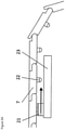
- the device for producing the three-dimensional models may include a tunnel, such as illustrated in FIG. 1 .
- the build apparatus may apply build material to the feedstock before the feedstock enters the tunnel with a dosing unit.
- the feedstock is conveyed through the tunnel in a conveyance direction 17 .
- the tunnel may be formed by walls 4 .
- the tunnel has a side wall 4 having an edge 37 that is angled relative to the conveyance direction 17 and is angled relative to a direction perpendicular to a surface of the conveyor.
- the feedstock 3 fills the entry opening of the tunnel 38 , such as illustrated in FIG. 1 .
- the coater 1 preferably applies the particulate material directly to the feedstock 3 , such as illustrated in FIG. 1 .
- the coater 1 may move on linear guides 8 , such as illustrated in FIG. 1 .
- the coater 1 preferably is outside of the tunnel 38 , such as illustrated in FIG. 1 .
- the linear guides 8 are preferably outside of the tunnel 38 , such as illustrated in FIG. 1 .
- the tunnel 38 preferably at least partially supports the feedstock 3 , such as illustrated in FIG. 1 .
- FIG. 2 shows a preferred link conveyor according to the invention, including hinges which permit mobility only in one direction.
- the link conveyor is moved by a roller track in this case. Only one, multiple or all rollers may be driven.
- FIG. 3 a shows a preferred transport unit according to the invention, comprising conveyor belt ( 7 ) (preferably a link conveyor as in FIG. 2 ), which is driven laterally by driving rollers ( 14 ) and is supported on small rollers ( 15 ) in the middle.
- conveyor belt ( 7 ) preferably a link conveyor as in FIG. 2
- FIG. 3 b shows a similar structure, in which conveyor belt ( 7 ) rests on continuous driving rollers ( 17 ) over its complete width.
- pressing rollers ( 13 ) press the conveyor belt onto the driving rollers ( 14 ) or driving cylinders ( 17 ).
- FIGS. 4 a and 4 b show a preferred structure according to the invention, in which the driving rollers ( 14 ) are driven by a shared driving belt ( 18 ). Conveyor belt ( 7 ) may then rest on the driving belt and be additionally supported.
- Conveyor belt ( 7 ) may then rest on the driving belt and be additionally supported.
- the middle of conveyor belt ( 7 ) is supported on sliding elements ( 19 ) made of, e.g., plastic.
- the middle of the conveyor belt is carried by air cushions ( 20 ).
- FIGS. 5 a through 5 c show a structure according to the invention, comprising a link conveyor ( 7 ), which has a gripping element ( 22 ) on each link.
- a gripper which repeatedly grips and positions a gripping element, passes beneath the link conveyor. The sequence is gripping and positioning ( FIG. 5 a ), opening the gripper ( FIG. 5 b ), returning and regripping a link ( FIG. 5 c ).
- FIG. 6 also shows a structure according to the invention, including a link conveyor ( 7 ), which has a gripping element ( 22 ) on each link, according to the invention.
- gripping elements ( 22 ) are positioned by a rotating worm drive ( 24 ).
- FIG. 7 shows an oblique view of a preferred feed system according to the invention, including raised grates according to the invention.
- FIGS. 8 a through 8 c show the sequence of the feed system from FIG. 7 , from the front and from the side in each case, according to the invention.
- FIG. 8 a shows the starting position when both lifting grate ( 26 ) and thrusting grate ( 27 ) carry the conveyor belt.
- lifting grate ( 26 ) has been extended and thrusting grate ( 27 ) subsequently lowered.
- lifting grate ( 26 ) has been lowered so that only thrusting grate ( 27 ) carries conveyor belt ( 7 ). Thrusting grate ( 27 ) then moves conveyor belt ( 7 ) into its next position.
- thrusting grate ( 27 ) In the lowered state, thrusting grate ( 27 ) returns to its starting position, as illustrated in FIG. 8 a.
- FIG. 9 shows a preferred structure according to the present invention with self-propelled building platforms ( 31 ). They are moved into building device ( 32 ).
- FIGS. 10 a through 10 c show additional preferred embodiments according to the invention.
- the feedstock is not produced linearly but rotatorily.
- the process begins at a first position or end and ends at a second position or end.
- FIG. 10 b is a view of FIG. 10 a from above.
- FIG. 10 c is a side view of FIG. 10 b of the cone printer according to the invention, on sectional plane A-A.
- ( 33 ) designates the outwardly oriented movement of coater ( 1 ) and solidification unit ( 2 ), which is indicated using directional arrows, the method being carried out on building platform ( 34 ), and a particulate material feedstock ( 3 ) being generated and components [produced], e.g., component ( 5 ), following solidification.
- building platform ( 34 ) is rotated, while coater ( 1 ) and the print axis move away from the rotation axis.
- Coater ( 1 ) is rotated 90° with respect to the other preferred devices of the invention described above and may be operated continuously.
- Solidification unit ( 2 ) may also work continuously, whereby a plurality of components may be produced in this manner on one building platform ( 34 ) in one operation (batch).
- a build cone ( 21 ) may be used to start the system.
- the alpha angle may be changed, depending on the particulate material, and thus be optimally adapted to the particular particulate material used.
- This device type requires the data for the molds for the components to be produced to be skewed not only linearly but also on the basis of polar coordinates.
- the dimensions of the cone printer and the building platform as well as the device as a whole may be selected in such a way that both very small and very large and heavy components may be produced without distortion.
- FIG. 11 shows a preferred building device ( 32 ) according to the invention, to the end of which an unpacking area, including a roller track ( 35 ), is connected.
- the finished components are deposited directly onto the roller track. Loose particulate material may run off between the rollers and thus support unpacking.
- the roller track may be driven or it may run passively.
- FIG. 12 shows a preferred building device according to the invention with a rotating building platform ( 34 ).
- Coater ( 1 ) and solidification unit ( 2 ) move only translatorily, while building platform ( 34 ) continues to rotate layer by layer and thus continuously builds up material feedstock ( 3 ).
- the device in FIG. 12 may be configured in such a way that it is combined with an unpacking station or an unpacking operation in an arbitrary position. Finished components ( 5 ) are shifted to a position ( 36 ) inside or outside or below or above building platform ( 34 ) and freed of the remaining loose particulate material simultaneously or in another work step.
- the process begins at a first position or end, e.g., at the point of the first particulate material application, and ends at a second position or end, e.g., upon completion of the component or preferably at the point of unpacking.
- the loose particulate material may be resupplied cyclically to the further continuous process.
- the particulate material supply is thus limited to the quantities which are removed from circulation in the form of components and any non-reusable quantities.
- FIGS. 13 a through 13 f show a drive for belts or link aprons with lifting grates ( 26 ) and thrusting grates ( 27 ) according to the principle of the step conveyor. Thrusting grate ( 27 ) moves on lever arms which swivel back and forth. Lifting grate ( 26 ) is raised on the return swiveling motion.
- FIGS. 14 a through 14 d show a drive for belts or link aprons with lifting grates ( 26 ) and thrusting grates ( 27 ) according to the principle of the step conveyor. Thrusting grate ( 27 ) moves on rotating lever arms.
- FIGS. 15 a through 15 d show a drive for belts or link aprons with lifting grates ( 26 ) and thrusting grates ( 27 ) according to the principle of the step conveyor.
- a vertical lifting of lifting grate ( 26 ) alternates with an inclined lifting of thrusting grate ( 27 ).
Abstract
Description
-
- Continuous feed (continuous conveyor)
- Vibration-free feed
- High positioning accuracy in the range of just a few micrometers (e.g., 1 μm)
- High rigidity in the conveyance direction under high loads (tensile loads up to several tons)
- High rigidity in the vertical direction (weight load up to several tons)
- Resistance of the supporting surface to contamination with the build material (e.g., abrasive sands/particulate material or aggressive solvents)
- Density of the supporting surface in order to prevent runoff of the build material.
- No stick-slip effects
- Minimal maintenance with almost non-stop operation
- Cost-effective construction
-
- Roller tracks
- Ball tracks
- Sliding materials (e.g., plastics, non-ferrous heavy metals)
- Air cushions
- Hydrodynamic bearing of the individual links
- Hydrostatic bearing of the individual links
-
- 1 Coater
- 2 Solidification unit
- 3 Powder cake/particulate material feedstock
- 4 Tunnel wall
- 5 Component (being built)
- 6 Roller for cover belt
- 7 Conveyor belt (e.g., link conveyor)
- 8 Linear unit
- 9 Build space
- 10 Link with hinge
- 11 Driving cylinder
- 12 Cylinder bearing
- 13 Pressing roller
- 14 Driving roller
- 15 Bearing roller
- 16 Motor
- 17 Conveyance direction
- 18 Driving belt (e.g., toothed belt)
- 19 Sliding element
- 20 Air cushion
- 21 Gripper
- 22 Gripping element
- 23 Linear feed
- 24 Worm wheel
- 25 Frame
- 26 Lifting grate
- 27 Thrusting grate
- 28 Linear bearing
- 29 Lifting unit for lifting grate
- 30 Lifting unit for thrusting grate
- 31 Self-propelled building platform
- 32 Building device
- 33 Direction of movement of the coater and the solidification unit
- 34 Rotating building platform
- 35 Roller track
- 36 Unpacking area
- 37 Edge of tunnel wall
- 38 Entry opening of the tunnel
Claims (20)
Priority Applications (1)
| Application Number | Priority Date | Filing Date | Title |
|---|---|---|---|
| US16/245,831 US11225029B2 (en) | 2012-05-25 | 2019-01-11 | Device for producing three-dimensional models and methods thereof |
Applications Claiming Priority (5)
| Application Number | Priority Date | Filing Date | Title |
|---|---|---|---|
| DE102012010272.0 | 2012-05-25 | ||
| DE102012010272A DE102012010272A1 (en) | 2012-05-25 | 2012-05-25 | Method for producing three-dimensional models with special construction platforms and drive systems |
| PCT/DE2013/000271 WO2013174361A1 (en) | 2012-05-25 | 2013-05-17 | Device for producing three-dimensional models with special building platforms and drive systems |
| US16/047,710 US20180345585A1 (en) | 2012-05-25 | 2018-07-27 | Device for producing three-dimensional models with special building platforms and drive systems |
| US16/245,831 US11225029B2 (en) | 2012-05-25 | 2019-01-11 | Device for producing three-dimensional models and methods thereof |
Related Parent Applications (1)
| Application Number | Title | Priority Date | Filing Date |
|---|---|---|---|
| US16/047,710 Continuation US20180345585A1 (en) | 2012-05-25 | 2018-07-27 | Device for producing three-dimensional models with special building platforms and drive systems |
Publications (2)
| Publication Number | Publication Date |
|---|---|
| US20190143608A1 US20190143608A1 (en) | 2019-05-16 |
| US11225029B2 true US11225029B2 (en) | 2022-01-18 |
Family
ID=48698851
Family Applications (4)
| Application Number | Title | Priority Date | Filing Date |
|---|---|---|---|
| US14/400,957 Active 2035-05-09 US10059062B2 (en) | 2012-05-25 | 2013-05-17 | Device for producing three-dimensional models with special building platforms and drive systems |
| US16/038,913 Abandoned US20180326654A1 (en) | 2012-05-25 | 2018-07-18 | Device for producing three-dimensional models with special building platforms and drive systems |
| US16/047,710 Abandoned US20180345585A1 (en) | 2012-05-25 | 2018-07-27 | Device for producing three-dimensional models with special building platforms and drive systems |
| US16/245,831 Active 2033-07-10 US11225029B2 (en) | 2012-05-25 | 2019-01-11 | Device for producing three-dimensional models and methods thereof |
Family Applications Before (3)
| Application Number | Title | Priority Date | Filing Date |
|---|---|---|---|
| US14/400,957 Active 2035-05-09 US10059062B2 (en) | 2012-05-25 | 2013-05-17 | Device for producing three-dimensional models with special building platforms and drive systems |
| US16/038,913 Abandoned US20180326654A1 (en) | 2012-05-25 | 2018-07-18 | Device for producing three-dimensional models with special building platforms and drive systems |
| US16/047,710 Abandoned US20180345585A1 (en) | 2012-05-25 | 2018-07-27 | Device for producing three-dimensional models with special building platforms and drive systems |
Country Status (6)
| Country | Link |
|---|---|
| US (4) | US10059062B2 (en) |
| EP (1) | EP2855121B1 (en) |
| KR (1) | KR102070922B1 (en) |
| CN (1) | CN104379323B (en) |
| DE (1) | DE102012010272A1 (en) |
| WO (1) | WO2013174361A1 (en) |
Families Citing this family (69)
| Publication number | Priority date | Publication date | Assignee | Title |
|---|---|---|---|---|
| EP1324842B1 (en) | 2000-09-25 | 2007-12-19 | Voxeljet Technology GmbH | Method for producing a part using a deposition technique |
| DE102006038858A1 (en) | 2006-08-20 | 2008-02-21 | Voxeljet Technology Gmbh | Self-hardening material and method for layering models |
| US10226919B2 (en) | 2007-07-18 | 2019-03-12 | Voxeljet Ag | Articles and structures prepared by three-dimensional printing method |
| DE102007050679A1 (en) | 2007-10-21 | 2009-04-23 | Voxeljet Technology Gmbh | Method and device for conveying particulate material in the layered construction of models |
| DE102007050953A1 (en) | 2007-10-23 | 2009-04-30 | Voxeljet Technology Gmbh | Device for the layered construction of models |
| DE102010006939A1 (en) | 2010-02-04 | 2011-08-04 | Voxeljet Technology GmbH, 86167 | Device for producing three-dimensional models |
| DE102010014969A1 (en) | 2010-04-14 | 2011-10-20 | Voxeljet Technology Gmbh | Device for producing three-dimensional models |
| DE102010015451A1 (en) | 2010-04-17 | 2011-10-20 | Voxeljet Technology Gmbh | Method and device for producing three-dimensional objects |
| DE102010056346A1 (en) | 2010-12-29 | 2012-07-05 | Technische Universität München | Method for the layered construction of models |
| DE102011007957A1 (en) | 2011-01-05 | 2012-07-05 | Voxeljet Technology Gmbh | Device and method for constructing a layer body with at least one body limiting the construction field and adjustable in terms of its position |
| DE102011105688A1 (en) | 2011-06-22 | 2012-12-27 | Hüttenes-Albertus Chemische Werke GmbH | Method for the layered construction of models |
| DE102011111498A1 (en) | 2011-08-31 | 2013-02-28 | Voxeljet Technology Gmbh | Device for the layered construction of models |
| DE102012004213A1 (en) | 2012-03-06 | 2013-09-12 | Voxeljet Technology Gmbh | Method and device for producing three-dimensional models |
| DE102012010272A1 (en) | 2012-05-25 | 2013-11-28 | Voxeljet Technology Gmbh | Method for producing three-dimensional models with special construction platforms and drive systems |
| DE102012012363A1 (en) | 2012-06-22 | 2013-12-24 | Voxeljet Technology Gmbh | Apparatus for building up a layer body with a storage or filling container movable along the discharge container |
| US8888480B2 (en) * | 2012-09-05 | 2014-11-18 | Aprecia Pharmaceuticals Company | Three-dimensional printing system and equipment assembly |
| DE102012020000A1 (en) | 2012-10-12 | 2014-04-17 | Voxeljet Ag | 3D multi-stage process |
| DE102013004940A1 (en) | 2012-10-15 | 2014-04-17 | Voxeljet Ag | Method and device for producing three-dimensional models with tempered printhead |
| US10987868B2 (en) * | 2012-10-31 | 2021-04-27 | Nederlandse Organisatie Voor Toegepast-Natuurwetenschappelijk Onderzoek Tno | Production line for making tangible products by layerwise manufacturing |
| EP2727709A1 (en) * | 2012-10-31 | 2014-05-07 | Nederlandse Organisatie voor toegepast -natuurwetenschappelijk onderzoek TNO | Method and apparatus for making tangible products by layerwise manufacturing |
| DE102012022859A1 (en) | 2012-11-25 | 2014-05-28 | Voxeljet Ag | Construction of a 3D printing device for the production of components |
| DE102013003303A1 (en) | 2013-02-28 | 2014-08-28 | FluidSolids AG | Process for producing a molded part with a water-soluble casting mold and material system for its production |
| DE102013018182A1 (en) | 2013-10-30 | 2015-04-30 | Voxeljet Ag | Method and device for producing three-dimensional models with binder system |
| DE102013018031A1 (en) | 2013-12-02 | 2015-06-03 | Voxeljet Ag | Swap body with movable side wall |
| DE102013020491A1 (en) | 2013-12-11 | 2015-06-11 | Voxeljet Ag | 3D infiltration process |
| DE102013021091A1 (en) | 2013-12-18 | 2015-06-18 | Voxeljet Ag | 3D printing process with rapid drying step |
| EP2886307A1 (en) | 2013-12-20 | 2015-06-24 | Voxeljet AG | Device, special paper and method for the production of moulded components |
| DE102013021891A1 (en) | 2013-12-23 | 2015-06-25 | Voxeljet Ag | Apparatus and method with accelerated process control for 3D printing processes |
| WO2015108849A1 (en) * | 2014-01-14 | 2015-07-23 | United Technologies Corporation | Systems and processes for distributing material during additive manufacturing |
| DE102014004692A1 (en) | 2014-03-31 | 2015-10-15 | Voxeljet Ag | Method and apparatus for 3D printing with conditioned process control |
| DE102014007584A1 (en) | 2014-05-26 | 2015-11-26 | Voxeljet Ag | 3D reverse printing method and apparatus |
| EP3174651B1 (en) | 2014-08-02 | 2020-06-17 | voxeljet AG | Method and casting mould, in particular for use in cold casting methods |
| DE102014014895A1 (en) | 2014-10-13 | 2016-04-14 | Voxeljet Ag | Method and device for producing components in a layer construction method |
| DE102015006533A1 (en) | 2014-12-22 | 2016-06-23 | Voxeljet Ag | Method and device for producing 3D molded parts with layer construction technique |
| DE102015003372A1 (en) | 2015-03-17 | 2016-09-22 | Voxeljet Ag | Method and device for producing 3D molded parts with double recoater |
| DE102015006363A1 (en) | 2015-05-20 | 2016-12-15 | Voxeljet Ag | Phenolic resin method |
| US10357827B2 (en) * | 2015-07-29 | 2019-07-23 | General Electric Comany | Apparatus and methods for production additive manufacturing |
| MX2018001940A (en) | 2015-08-21 | 2018-11-09 | Aprecia Pharmaceuticals LLC | Three-dimensional printing system and equipment assembly. |
| DE102015011503A1 (en) | 2015-09-09 | 2017-03-09 | Voxeljet Ag | Method for applying fluids |
| DE102015011790A1 (en) | 2015-09-16 | 2017-03-16 | Voxeljet Ag | Device and method for producing three-dimensional molded parts |
| WO2017075600A1 (en) * | 2015-10-30 | 2017-05-04 | Stratasys, Inc. | Platen removal for additive manufacturing system |
| CN113561478B (en) | 2015-10-30 | 2023-06-06 | 速尔特技术有限公司 | Additive manufacturing system and method |
| DE102015015353A1 (en) | 2015-12-01 | 2017-06-01 | Voxeljet Ag | Method and device for producing three-dimensional components by means of an excess quantity sensor |
| CN105459408B (en) * | 2016-01-29 | 2017-06-27 | 芜湖市爱三迪电子科技有限公司 | A kind of 3D printer for automatically stripping model and continuous printing |
| WO2017184351A1 (en) * | 2016-04-19 | 2017-10-26 | Laitram, L.L.C. | Air bearing conveyor |
| CN108016035A (en) * | 2016-10-31 | 2018-05-11 | 无锡金谷三维科技有限公司 | A kind of 3 D-printing production line system of continuous rapid operation |
| DE102016013610A1 (en) | 2016-11-15 | 2018-05-17 | Voxeljet Ag | Intra-head printhead maintenance station for powder bed-based 3D printing |
| NL2018728B1 (en) * | 2017-04-18 | 2018-10-29 | Stephan Schuermann Holding B V | A gantry-type three dimensional printing apparatus for printing a three dimensional work piece in a layer wise manner. |
| AU2018280333B2 (en) * | 2017-06-06 | 2023-10-26 | Aurora Labs Limited | 3D printing method and apparatus |
| CN107081909A (en) * | 2017-06-29 | 2017-08-22 | 温州启龙电子科技有限公司 | A kind of new 3D printer |
| DE102017006860A1 (en) | 2017-07-21 | 2019-01-24 | Voxeljet Ag | Method and device for producing 3D molded parts with spectrum converter |
| US11565468B1 (en) * | 2017-12-07 | 2023-01-31 | Redwire Space, Inc. | System and method for hybrid additive and subtractive manufacturing with dimensional verification |
| US11584057B2 (en) | 2018-01-03 | 2023-02-21 | General Electric Company | Systems and methods for additive manufacturing |
| US20210268715A1 (en) * | 2018-08-09 | 2021-09-02 | University Of Maine System Board Of Trustees | Non-orthogonal additive manufacturing and the treatment of parts manufactured thereof |
| US11104060B2 (en) | 2018-08-29 | 2021-08-31 | Massachusetts Institute Of Technology | Methods and apparatus for fabrication with a movable sheet |
| CN109352987A (en) * | 2018-11-23 | 2019-02-19 | 南京工业职业技术学院 | Technical grade infinite size 3D printer |
| US11426939B2 (en) * | 2019-01-11 | 2022-08-30 | International Business Machines Corporation | Three dimensional printer |
| DE102019000796A1 (en) | 2019-02-05 | 2020-08-06 | Voxeljet Ag | Exchangeable process unit |
| FR3093940B1 (en) * | 2019-03-21 | 2023-11-24 | Safran Trans Systems | Device for manufacturing by selective fusion on a powder bed |
| AT522560B1 (en) * | 2019-05-29 | 2020-12-15 | Progress Maschinen & Automation Ag | Arrangement for producing at least one three-dimensional component for the construction industry |
| DE102019208830A1 (en) * | 2019-06-18 | 2020-12-24 | Volkswagen Aktiengesellschaft | Manufacturing system for use in an additive manufacturing process, carrier plate device, support body, sealing device |
| ES1233349Y (en) | 2019-06-19 | 2019-10-25 | Fund Eurecat | ADDITIVE STRATEG PRINTER |
| DE102019209991A1 (en) * | 2019-07-08 | 2021-01-14 | Volkswagen Aktiengesellschaft | Transport device for use in an additive manufacturing process as well as a sealing element and a manufacturing system for use in an additive manufacturing process |
| DE102019007595A1 (en) | 2019-11-01 | 2021-05-06 | Voxeljet Ag | 3D PRINTING PROCESS AND MOLDED PART MANUFACTURED WITH LIGNINE SULPHATE |
| KR102292615B1 (en) * | 2019-12-31 | 2021-08-24 | (주)쓰리디머티리얼즈 | Continuative 3D printing process |
| CN111016170A (en) * | 2019-12-31 | 2020-04-17 | 陈正鹏 | 3D printer and printing equipment |
| US11504879B2 (en) | 2020-04-17 | 2022-11-22 | Beehive Industries, LLC | Powder spreading apparatus and system |
| DE102020210570A1 (en) | 2020-08-20 | 2022-02-24 | Hennig Holding Gmbh | Sectional apron for covering openings and covering device for openings |
| WO2023238089A1 (en) * | 2022-06-09 | 2023-12-14 | Caracol S.R.L. | Apparatus and method for supporting an article in the course of manufacture by an additive manufacturing process |
Citations (353)
| Publication number | Priority date | Publication date | Assignee | Title |
|---|---|---|---|---|
| US3850213A (en) | 1973-09-26 | 1974-11-26 | C Keaton | Continuous press |
| US3913503A (en) | 1972-12-15 | 1975-10-21 | Becker Karl Masch | Apparatus for planting individual seeds in predetermined locations |
| US4198260A (en) | 1977-03-01 | 1980-04-15 | Windmoller & Holscher | Apparatus for severing a stack of filmlike sections and simultaneously forming them into blocks |
| US4247508A (en) | 1979-12-03 | 1981-01-27 | Hico Western Products Co. | Molding process |
| SU821339A1 (en) | 1976-08-18 | 1981-04-15 | Всесоюзный Проектно-Конструкторскийинститут Сварочного Производства(Висп) | Trolley conveyer |
| DE3221357A1 (en) | 1982-06-05 | 1983-12-08 | Plasticonsult GmbH Beratungsgesellschaft für Kunststoff- und Oberflächentechnik, 6360 Friedberg | Process for the production of moulds and cores for casting purposes |
| US4575330A (en) | 1984-08-08 | 1986-03-11 | Uvp, Inc. | Apparatus for production of three-dimensional objects by stereolithography |
| US4591402A (en) | 1981-06-22 | 1986-05-27 | Ltv Aerospace And Defense Company | Apparatus and method for manufacturing composite structures |
| US4600733A (en) | 1984-02-29 | 1986-07-15 | Nissan Motor Co., Ltd. | Disintegration assistant for casting molds |
| US4665492A (en) | 1984-07-02 | 1987-05-12 | Masters William E | Computer automated manufacturing process and system |
| US4669634A (en) | 1981-08-04 | 1987-06-02 | Roussel Uclaf | Apparatus and process for the metering of predetermined quantities of at least one product |
| JPS62275734A (en) | 1986-05-26 | 1987-11-30 | Tokieda Naomitsu | Method for forming solid |
| US4711669A (en) | 1985-11-05 | 1987-12-08 | American Cyanamid Company | Method of manufacturing a bonded particulate article by reacting a hydrolyzed amylaceous product and a heterocyclic compound |
| US4752498A (en) | 1987-03-02 | 1988-06-21 | Fudim Efrem V | Method and apparatus for production of three-dimensional objects by photosolidification |
| US4752352A (en) | 1986-06-06 | 1988-06-21 | Michael Feygin | Apparatus and method for forming an integral object from laminations |
| US4863538A (en) | 1986-10-17 | 1989-09-05 | Board Of Regents, The University Of Texas System | Method and apparatus for producing parts by selective sintering |
| US4944817A (en) | 1986-10-17 | 1990-07-31 | Board Of Regents, The University Of Texas System | Multiple material systems for selective beam sintering |
| US5017753A (en) | 1986-10-17 | 1991-05-21 | Board Of Regents, The University Of Texas System | Method and apparatus for producing parts by selective sintering |
| US5031120A (en) | 1987-12-23 | 1991-07-09 | Itzchak Pomerantz | Three dimensional modelling apparatus |
| US5047182A (en) | 1987-11-25 | 1991-09-10 | Ceramics Process Systems Corporation | Complex ceramic and metallic shaped by low pressure forming and sublimative drying |
| US5053090A (en) | 1989-09-05 | 1991-10-01 | Board Of Regents, The University Of Texas System | Selective laser sintering with assisted powder handling |
| US5059266A (en) | 1989-05-23 | 1991-10-22 | Brother Kogyo Kabushiki Kaisha | Apparatus and method for forming three-dimensional article |
| US5064583A (en) * | 1989-08-01 | 1991-11-12 | Zycon Corporation | Method for applying mold release coating to separator plates for molding printed circuit boards |
| US5076869A (en) | 1986-10-17 | 1991-12-31 | Board Of Regents, The University Of Texas System | Multiple material systems for selective beam sintering |
| US5120476A (en) | 1989-12-23 | 1992-06-09 | Basf Aktiengesellschaft | Production of objects |
| US5126529A (en) | 1990-12-03 | 1992-06-30 | Weiss Lee E | Method and apparatus for fabrication of three-dimensional articles by thermal spray deposition |
| US5127037A (en) | 1990-08-15 | 1992-06-30 | Bynum David K | Apparatus for forming a three-dimensional reproduction of an object from laminations |
| US5132143A (en) | 1986-10-17 | 1992-07-21 | Board Of Regents, The University Of Texas System | Method for producing parts |
| US5134569A (en) | 1989-06-26 | 1992-07-28 | Masters William E | System and method for computer automated manufacturing using fluent material |
| DE4102260A1 (en) | 1991-01-23 | 1992-07-30 | Artos Med Produkte | Apparatus for making shaped articles - has laser beam directed through transparent base of tank which contains laser-curable liquid and is sealed off by movable cover plate |
| US5136515A (en) | 1989-11-07 | 1992-08-04 | Richard Helinski | Method and means for constructing three-dimensional articles by particle deposition |
| US5140937A (en) | 1989-05-23 | 1992-08-25 | Brother Kogyo Kabushiki Kaisha | Apparatus for forming three-dimensional article |
| US5147587A (en) | 1986-10-17 | 1992-09-15 | Board Of Regents, The University Of Texas System | Method of producing parts and molds using composite ceramic powders |
| US5149548A (en) | 1989-07-03 | 1992-09-22 | Brother Kogyo Kabushiki Kaisha | Apparatus for forming three-dimension article |
| US5155324A (en) | 1986-10-17 | 1992-10-13 | Deckard Carl R | Method for selective laser sintering with layerwise cross-scanning |
| US5156697A (en) | 1989-09-05 | 1992-10-20 | Board Of Regents, The University Of Texas System | Selective laser sintering of parts by compound formation of precursor powders |
| US5182170A (en) | 1989-09-05 | 1993-01-26 | Board Of Regents, The University Of Texas System | Method of producing parts by selective beam interaction of powder with gas phase reactant |
| US5204055A (en) | 1989-12-08 | 1993-04-20 | Massachusetts Institute Of Technology | Three-dimensional printing techniques |
| DE3930750C2 (en) | 1989-09-14 | 1993-05-27 | Krupp Medizintechnik Gmbh, 4300 Essen, De | |
| US5216616A (en) | 1989-06-26 | 1993-06-01 | Masters William E | System and method for computer automated manufacture with reduced object shape distortion |
| US5229209A (en) | 1990-03-30 | 1993-07-20 | Tioxide Group Plc | Preparation of vesiculated core/shell polymeric particles |
| US5248456A (en) | 1989-06-12 | 1993-09-28 | 3D Systems, Inc. | Method and apparatus for cleaning stereolithographically produced objects |
| US5252264A (en) | 1991-11-08 | 1993-10-12 | Dtm Corporation | Apparatus and method for producing parts with multi-directional powder delivery |
| US5263130A (en) | 1986-06-03 | 1993-11-16 | Cubital Ltd. | Three dimensional modelling apparatus |
| US5269982A (en) | 1992-02-12 | 1993-12-14 | Brotz Gregory R | Process for manufacturing a shaped product |
| US5284695A (en) | 1989-09-05 | 1994-02-08 | Board Of Regents, The University Of Texas System | Method of producing high-temperature parts by way of low-temperature sintering |
| US5296062A (en) | 1986-10-17 | 1994-03-22 | The Board Of Regents, The University Of Texas System | Multiple material systems for selective beam sintering |
| DE4305201C1 (en) | 1993-02-19 | 1994-04-07 | Eos Electro Optical Syst | Three dimensional component mfr with laser-cured resin and filler - involves mixing steel or ceramic powder in resin, laser curing given shape, heating in nitrogen@ atmosphere and nitric acid to remove resin and then sintering filler |
| US5324617A (en) | 1991-06-28 | 1994-06-28 | Sony Corporation | Printing material comprising a combustible material suitable for creating pits on irradiation with a laser beam |
| JPH06198746A (en) | 1992-12-28 | 1994-07-19 | Olympus Optical Co Ltd | Three-dimensional model forming device |
| US5342919A (en) | 1992-11-23 | 1994-08-30 | Dtm Corporation | Sinterable semi-crystalline powder and near-fully dense article formed therewith |
| US5352405A (en) | 1992-12-18 | 1994-10-04 | Dtm Corporation | Thermal control of selective laser sintering via control of the laser scan |
| US5354414A (en) | 1988-10-05 | 1994-10-11 | Michael Feygin | Apparatus and method for forming an integral object from laminations |
| DE4325573A1 (en) | 1993-07-30 | 1995-02-02 | Stephan Herrmann | Apparatus for the gradual application of powder layers one on top of the other |
| US5387380A (en) | 1989-12-08 | 1995-02-07 | Massachusetts Institute Of Technology | Three-dimensional printing techniques |
| US5398193A (en) | 1993-08-20 | 1995-03-14 | Deangelis; Alfredo O. | Method of three-dimensional rapid prototyping through controlled layerwise deposition/extraction and apparatus therefor |
| US5418112A (en) | 1993-11-10 | 1995-05-23 | W. R. Grace & Co.-Conn. | Photosensitive compositions useful in three-dimensional part-building and having improved photospeed |
| DE29506204U1 (en) | 1995-04-10 | 1995-06-01 | Eos Electro Optical Syst | Device for producing a three-dimensional object |
| US5427722A (en) | 1993-06-11 | 1995-06-27 | General Motors Corporation | Pressure slip casting process for making hollow-shaped ceramics |
| US5431967A (en) | 1989-09-05 | 1995-07-11 | Board Of Regents, The University Of Texas System | Selective laser sintering using nanocomposite materials |
| US5433261A (en) | 1993-04-30 | 1995-07-18 | Lanxide Technology Company, Lp | Methods for fabricating shapes by use of organometallic, ceramic precursor binders |
| US5433773A (en) * | 1994-06-02 | 1995-07-18 | Fremont Industries, Inc. | Method and composition for treatment of phosphate coated metal surfaces |
| DE4440397C1 (en) | 1994-11-11 | 1995-09-21 | Eos Electro Optical Syst | Casting mould prodn. process |
| US5456348A (en) | 1993-02-05 | 1995-10-10 | Axia Incorporated | Powered flexible conveyor |
| EP0361847B1 (en) | 1988-09-26 | 1995-11-29 | 3D Systems, Inc. | Recoating of stereolithographic layers |
| US5482659A (en) | 1994-12-22 | 1996-01-09 | United Technologies Corporation | Method of post processing stereolithographically produced objects |
| US5490962A (en) | 1993-10-18 | 1996-02-13 | Massachusetts Institute Of Technology | Preparation of medical devices by solid free-form fabrication methods |
| US5503785A (en) | 1994-06-02 | 1996-04-02 | Stratasys, Inc. | Process of support removal for fused deposition modeling |
| US5506607A (en) | 1991-01-25 | 1996-04-09 | Sanders Prototypes Inc. | 3-D model maker |
| US5518680A (en) | 1993-10-18 | 1996-05-21 | Massachusetts Institute Of Technology | Tissue regeneration matrices by solid free form fabrication techniques |
| US5518060A (en) | 1994-01-25 | 1996-05-21 | Brunswick Corporation | Method of producing polymeric patterns for use in evaporable foam casting |
| GB2297516A (en) | 1995-02-01 | 1996-08-07 | Steven Butterworth | Production of 3-D prototypes from computer generated models |
| US5555176A (en) | 1994-10-19 | 1996-09-10 | Bpm Technology, Inc. | Apparatus and method for making three-dimensional articles using bursts of droplets |
| US5573721A (en) | 1995-02-16 | 1996-11-12 | Hercules Incorporated | Use of a support liquid to manufacture three-dimensional objects |
| US5589222A (en) | 1992-06-18 | 1996-12-31 | Ferro (Italia) S.R.L. | Hydrophobic free-flowing pellets, a process for their production and their use |
| DE19525307A1 (en) | 1995-07-12 | 1997-01-16 | Eichenauer Gmbh & Co Kg F | Casting core for molds |
| DE19530295C1 (en) | 1995-08-11 | 1997-01-30 | Eos Electro Optical Syst | Device for producing an object in layers by means of laser sintering |
| DE19528215A1 (en) | 1995-08-01 | 1997-02-06 | Thomas Dipl Ing Himmer | Three=dimensional model or tool mfr. employing rapid prototyping methods - involves building up layers of different materials according to use and processing each layer by a variety of chemical, physical or mechanical methods |
| US5616631A (en) | 1994-08-17 | 1997-04-01 | Kao Corporation | Binder composition for mold making, binder/curing agent composition for mold making, sand composition for mold making, and process of making mold |
| DE29701279U1 (en) | 1997-01-27 | 1997-05-22 | Eos Electro Optical Syst | Device with a process chamber and an element which can be moved back and forth in the process chamber |
| DE19545167A1 (en) | 1995-12-04 | 1997-06-05 | Bayerische Motoren Werke Ag | Method of manufacturing a prototype component or tool from a stereo-sintered polystyrene pattern |
| US5637175A (en) | 1988-10-05 | 1997-06-10 | Helisys Corporation | Apparatus for forming an integral object from laminations |
| US5639402A (en) | 1994-08-08 | 1997-06-17 | Barlow; Joel W. | Method for fabricating artificial bone implant green parts |
| US5647931A (en) | 1994-01-11 | 1997-07-15 | Eos Gmbh Electro Optical Systems | Method and apparatus for producing a three-dimensional object |
| US5658412A (en) | 1993-01-11 | 1997-08-19 | Eos Gmbh Electro Optical Systems | Method and apparatus for producing a three-dimensional object |
| US5665401A (en) | 1995-04-25 | 1997-09-09 | Eos Gmbh Electro Optical Systems | Apparatus for producing an object using stereolithography |
| US5717599A (en) | 1994-10-19 | 1998-02-10 | Bpm Technology, Inc. | Apparatus and method for dispensing build material to make a three-dimensional article |
| US5730925A (en) | 1995-04-21 | 1998-03-24 | Eos Gmbh Electro Optical Systems | Method and apparatus for producing a three-dimensional object |
| DE69031808T2 (en) | 1989-09-05 | 1998-04-02 | Univ Texas | Multi-material systems for sintering with selective radiation using powder |
| US5740051A (en) | 1991-01-25 | 1998-04-14 | Sanders Prototypes, Inc. | 3-D model making |
| US5749041A (en) | 1995-10-13 | 1998-05-05 | Dtm Corporation | Method of forming three-dimensional articles using thermosetting materials |
| US5747105A (en) | 1996-04-30 | 1998-05-05 | Owens Corning Fiberglas Technology Inc. | Traversing nozzle for applying granules to an asphalt coated sheet |
| US5753274A (en) | 1995-03-30 | 1998-05-19 | Eos Gmbh Electronics Optical Systems | Apparatus for producing a three-dimensional object |
| US5837960A (en) | 1995-08-14 | 1998-11-17 | The Regents Of The University Of California | Laser production of articles from powders |
| US5851465A (en) | 1995-12-29 | 1998-12-22 | Massachusetts Institute Of Technology | Binder composition for use in three dimensional printing |
| US5902441A (en) | 1996-09-04 | 1999-05-11 | Z Corporation | Method of three dimensional printing |
| US5902537A (en) | 1995-02-01 | 1999-05-11 | 3D Systems, Inc. | Rapid recoating of three-dimensional objects formed on a cross-sectional basis |
| US5934343A (en) | 1997-03-31 | 1999-08-10 | Therics, Inc | Method for dispensing of powders |
| US5940674A (en) | 1997-04-09 | 1999-08-17 | Massachusetts Institute Of Technology | Three-dimensional product manufacture using masks |
| US5943235A (en) | 1995-09-27 | 1999-08-24 | 3D Systems, Inc. | Rapid prototyping system and method with support region data processing |
| JPH11268845A (en) | 1998-02-11 | 1999-10-05 | Heidelberger Druckmas Ag | Device for conveying paper sheet or signature |
| US5989476A (en) | 1998-06-12 | 1999-11-23 | 3D Systems, Inc. | Process of making a molded refractory article |
| US5997795A (en) | 1997-05-29 | 1999-12-07 | Rutgers, The State University | Processes for forming photonic bandgap structures |
| US6007318A (en) | 1996-12-20 | 1999-12-28 | Z Corporation | Method and apparatus for prototyping a three-dimensional object |
| US6048954A (en) | 1994-07-22 | 2000-04-11 | The University Of Texas System Board Of Regents | Binder compositions for laser sintering processes |
| US6048188A (en) | 1988-04-18 | 2000-04-11 | 3D Systems, Inc. | Stereolithographic curl reduction |
| AU720255B2 (en) | 1996-03-06 | 2000-05-25 | BioZ, L.L.C | Method for formation of a three-dimensional body |
| DE19853834A1 (en) | 1998-11-21 | 2000-05-31 | Ingo Ederer | Production of casting molds comprises depositing particulate material on support, applying binder and hardener to form solidified structure in selected region, and removing solidified structure |
| US6133353A (en) | 1999-11-11 | 2000-10-17 | 3D Systems, Inc. | Phase change solid imaging material |
| US6147138A (en) | 1997-06-06 | 2000-11-14 | Generis Gmbh | Method for manufacturing of parts by a deposition technique |
| US6146567A (en) | 1993-02-18 | 2000-11-14 | Massachusetts Institute Of Technology | Three dimensional printing methods |
| US6155331A (en) | 1994-05-27 | 2000-12-05 | Eos Gmbh Electro Optical Systems | Method for use in casting technology |
| US6164850A (en) | 1996-06-04 | 2000-12-26 | Speakman; Stuart | 3D printing and forming of structures |
| US6165406A (en) | 1999-05-27 | 2000-12-26 | Nanotek Instruments, Inc. | 3-D color model making apparatus and process |
| US6169605B1 (en) | 1991-01-31 | 2001-01-02 | Texas Instruments Incorporated | Method and apparatus for the computer-controlled manufacture of three-dimensional objects from computer data |
| US6193922B1 (en) | 1997-04-13 | 2001-02-27 | Ingo Ederer | Method for making a three-dimensional body |
| US6210625B1 (en) | 1996-02-20 | 2001-04-03 | Mikuni Corporation | Method for producing granulated material |
| US6217816B1 (en) | 1999-12-24 | 2001-04-17 | National Science Council | Method for rapid forming of a ceramic work piece |
| US6216508B1 (en) | 1998-01-29 | 2001-04-17 | Amino Corporation | Apparatus for dieless forming plate materials |
| WO2001040866A2 (en) | 1999-11-29 | 2001-06-07 | Carl Johannes Fruth | Method and device for coating a substrate |
| US6259962B1 (en) | 1999-03-01 | 2001-07-10 | Objet Geometries Ltd. | Apparatus and method for three dimensional model printing |
| US6270335B2 (en) | 1995-09-27 | 2001-08-07 | 3D Systems, Inc. | Selective deposition modeling method and apparatus for forming three-dimensional objects and supports |
| US6305769B1 (en) | 1995-09-27 | 2001-10-23 | 3D Systems, Inc. | Selective deposition modeling system and method |
| WO2001078969A2 (en) | 2000-04-14 | 2001-10-25 | Z Corporation | Compositions for three-dimensional printing of solid objects |
| US6316060B1 (en) | 1996-08-20 | 2001-11-13 | Pacifica Papers Inc. | Metering coatings |
| US6318418B1 (en) | 1998-02-11 | 2001-11-20 | Robert Bosch Gmbh | Metering apparatus for pourable bulk material |
| US20010045678A1 (en) | 2000-05-25 | 2001-11-29 | Minolta Co., Ltd. | Three-dimensional modeling apparatus |
| US20010045345A1 (en) | 2000-05-15 | 2001-11-29 | Reguzzi Luigi | Conveyor device |
| US20010050031A1 (en) | 2000-04-14 | 2001-12-13 | Z Corporation | Compositions for three-dimensional printing of solid objects |
| US6335097B1 (en) | 1998-07-13 | 2002-01-01 | Toyota Jidosha Kabushiki Kaisha | Lamination molding resin-coated sand and lamination molding method using resin-coated sand |
| US6335052B1 (en) | 1999-01-20 | 2002-01-01 | Yazaki Corporation | Method of producing alumina particles |
| US20020000050A1 (en) | 2000-02-24 | 2002-01-03 | Ekhard Goldack | Apparatus for and process of drying articles |
| US20020000163A1 (en) | 2000-05-18 | 2002-01-03 | Giuliano Pegoraro | Method for heat treating a continuous strand of food product and apparatus adapted therefor |
| US20020002366A1 (en) | 1999-02-19 | 2002-01-03 | Michael Grasso | Laser lithotripsy device with suction |
| US20020015783A1 (en) | 2000-07-10 | 2002-02-07 | Rickey Harvey | Method and apparatus for sealing cracks in roads |
| US6350495B1 (en) | 1997-06-24 | 2002-02-26 | Dmc2 Degussa Metals Catalysts Cerdec Ag | Electrostatically applicable coating powder and processes therefor |
| US6355196B1 (en) | 1998-03-16 | 2002-03-12 | Vantico Inc. | Process for producing direct tooling mold and method for using the same |
| US6395811B1 (en) | 1999-11-11 | 2002-05-28 | 3D Systems, Inc. | Phase change solid imaging material |
| US6401001B1 (en) | 1999-07-22 | 2002-06-04 | Nanotek Instruments, Inc. | Layer manufacturing using deposition of fused droplets |
| US6405095B1 (en) | 1999-05-25 | 2002-06-11 | Nanotek Instruments, Inc. | Rapid prototyping and tooling system |
| US6403002B1 (en) | 1997-05-14 | 2002-06-11 | Buss Muller Technology Gmbh | Method and device for producing a shaped body |
| US20020073661A1 (en) * | 2000-11-03 | 2002-06-20 | Charles Beseler Company | Shrink-wrap packaging system |
| US20020079601A1 (en) | 1996-12-20 | 2002-06-27 | Z Corporation | Method and apparatus for prototyping a three-dimensional object |
| US20020090410A1 (en) | 2001-01-11 | 2002-07-11 | Shigeaki Tochimoto | Powder material removing apparatus and three dimensional modeling system |
| US6423255B1 (en) | 2000-03-24 | 2002-07-23 | Rainer Hoechsmann | Method for manufacturing a structural part by deposition technique |
| US20020111707A1 (en) | 2000-12-20 | 2002-08-15 | Zhimin Li | Droplet deposition method for rapid formation of 3-D objects from non-cross-linking reactive polymers |
| US6460979B1 (en) | 1999-03-15 | 2002-10-08 | Tally Computerdrucker Gmbh | Piezo bending transducer drop-on demand print head and method of actuating it |
| US20020155254A1 (en) | 2001-04-20 | 2002-10-24 | Mcquate William M. | Apparatus and method for placing particles in a pattern onto a substrate |
| US6476122B1 (en) | 1998-08-20 | 2002-11-05 | Vantico Inc. | Selective deposition modeling material |
| US20020167100A1 (en) | 2001-03-23 | 2002-11-14 | Ivoclar Vivadent Ag | Desktop process for producing dental products by means of 3-dimensional plotting |
| US6485831B1 (en) | 1999-05-13 | 2002-11-26 | Shin-Etsu Chemical Co., Ltd. | Conductive powder and making process |
| US6500378B1 (en) | 2000-07-13 | 2002-12-31 | Eom Technologies, L.L.C. | Method and apparatus for creating three-dimensional objects by cross-sectional lithography |
| US20030004599A1 (en) | 1999-12-31 | 2003-01-02 | Zsolt Herbak | Method of model construction |
| US20030007859A1 (en) | 2001-05-14 | 2003-01-09 | Hart Colin R. | Method and apparatus for stacking discrete planar objects |
| US20030065400A1 (en) | 2001-04-12 | 2003-04-03 | Beam Heather Ann | Method and apparatus for engineered regenrative biostructures such as hydroxyapatite substrates for bone healing applications |
| US6554600B1 (en) | 1998-10-09 | 2003-04-29 | Eos Gmbh Electro Optical Systems | Device for producing a three-dimensional object, especially a laser sintering machine |
| US20030083771A1 (en) | 2001-10-03 | 2003-05-01 | Schmidt Kris Alan | Selective deposition modeling with curable phase change materials |
| JP2003136605A (en) | 2001-11-06 | 2003-05-14 | Toshiba Corp | Method for forming product and its product |
| US20030113729A1 (en) | 2001-12-18 | 2003-06-19 | Daquino Lawrence J. | Multiple axis printhead adjuster for non-contact fluid deposition devices |
| US20030114936A1 (en) | 1998-10-12 | 2003-06-19 | Therics, Inc. | Complex three-dimensional composite scaffold resistant to delimination |
| US6596224B1 (en) | 1996-05-24 | 2003-07-22 | Massachusetts Institute Of Technology | Jetting layers of powder and the formation of fine powder beds thereby |
| US6616030B2 (en) | 2001-05-07 | 2003-09-09 | West Bond, Inc. | Gantry mounted ultrasonic wire bonder with orbital bonding tool head |
| US6658314B1 (en) | 1999-10-06 | 2003-12-02 | Objet Geometries Ltd. | System and method for three dimensional model printing |
| US6672343B1 (en) | 1999-06-21 | 2004-01-06 | Eos Gmbh Optical Systems | Device for supplying powder for a device for producing a three-dimensional object layer by layer |
| US20040003738A1 (en) | 2002-07-03 | 2004-01-08 | Therics, Inc. | Apparatus, systems and methods for use in three-dimensional printing |
| US20040012112A1 (en) | 1996-12-20 | 2004-01-22 | Z Corporation | Three-dimensional printer |
| US20040025905A1 (en) | 2000-10-04 | 2004-02-12 | Ingo Ederer | Method for unpacking shaped bodies embedded inside unbound particle material |
| US20040026418A1 (en) | 2000-09-26 | 2004-02-12 | Ingo Ederer | Interchangeable container |
| WO2004014637A1 (en) | 2002-08-02 | 2004-02-19 | Eos Gmbh Electro Optical Systems | Device and method for producing a three-dimensional object by means of a generative production method |
| US20040035542A1 (en) | 2000-09-26 | 2004-02-26 | Ingo Ederer | Device for manufacturing models layer by layer |
| US20040038009A1 (en) | 2002-08-21 | 2004-02-26 | Leyden Richard Noel | Water-based material systems and methods for 3D printing |
| US20040036200A1 (en) | 2001-02-15 | 2004-02-26 | Ranjana Patel | Three-dimensional structured printing |
| US20040045941A1 (en) | 2000-10-30 | 2004-03-11 | Frank Herzog | Device for sintering, removing material and/or labeling by means of electromagnetically bundled radiation |
| JP2004082206A (en) | 2002-08-27 | 2004-03-18 | Yoji Marutani | Forming method |
| US20040056378A1 (en) | 2002-09-25 | 2004-03-25 | Bredt James F. | Three dimensional printing material system and method |
| US6713125B1 (en) | 2002-03-13 | 2004-03-30 | 3D Systems, Inc. | Infiltration of three-dimensional objects formed by solid freeform fabrication |
| US6722872B1 (en) | 1999-06-23 | 2004-04-20 | Stratasys, Inc. | High temperature modeling apparatus |
| EP1415792A2 (en) | 1999-11-05 | 2004-05-06 | Z Corporation | Methods and compositions for three-dimensional printing |
| US20040084814A1 (en) | 2002-10-31 | 2004-05-06 | Boyd Melissa D. | Powder removal system for three-dimensional object fabricator |
| US6733528B2 (en) | 2001-08-09 | 2004-05-11 | Pentax Corporation | Implant forming method |
| US20040094058A1 (en) | 2002-11-14 | 2004-05-20 | Vladek Kasperchik | Rapid prototyping material systems |
| US20040112523A1 (en) | 2002-10-15 | 2004-06-17 | Crom Elden Wendell | Three dimensional printing from two dimensional printing devices |
| US20040138336A1 (en) | 1996-09-04 | 2004-07-15 | Z Corporation | Three dimensional printing material system and method |
| US6764636B1 (en) | 1999-03-01 | 2004-07-20 | 3D Systems, Inc. | Fast three-dimensional modeling method and device |
| US20040145088A1 (en) | 2001-05-24 | 2004-07-29 | Patel Ranjana C | Three-dimensional structured printing |
| US20040170765A1 (en) | 2001-04-10 | 2004-09-02 | Ingo Ederer | Method and device for applying fluids |
| EP1457590A1 (en) | 2003-03-10 | 2004-09-15 | Kuraray Co., Ltd. | Polyvinyl alcohol binder fibers, and paper and nonwoven fabric comprising them |
| US20040187714A1 (en) | 2000-03-13 | 2004-09-30 | Eduardo Napadensky | Compositons and methods for use in three dimensional model printing |
| US20040207123A1 (en) | 2001-02-15 | 2004-10-21 | Ranjana Patel | 3-D model maker |
| US20040239009A1 (en) | 2003-06-02 | 2004-12-02 | Collins David C. | Methods and systems for producting an object through solid freeform fabrication |
| US6827988B2 (en) | 2001-06-15 | 2004-12-07 | Technische Universitat Clausthal | Process and a device for producing ceramic molds |
| US6830643B1 (en) | 1999-11-16 | 2004-12-14 | 3D Systems Inc | Method of manufacturing an item and apparatus for manufacturing an item |
| US6838035B1 (en) | 1999-10-08 | 2005-01-04 | Voxeljet Technology Gmbh | Rapid-prototyping method and apparatus |
| US20050003189A1 (en) | 2003-05-21 | 2005-01-06 | Bredt James F. | Thermoplastic powder material system for appearance models from 3D prinitng systems |
| US20050000173A1 (en) | 2003-07-02 | 2005-01-06 | Vkr Holding A/S | Skylight with sealing gasket |
| US20050017394A1 (en) | 2003-06-16 | 2005-01-27 | Voxeljet Gmbh | Methods and systems for the manufacture of layered three-dimensional forms |
| US20050074511A1 (en) | 2003-10-03 | 2005-04-07 | Christopher Oriakhi | Solid free-form fabrication of solid three-dimesional objects |
| US20050093194A1 (en) | 2003-11-03 | 2005-05-05 | Christopher Oriakhi | Solid free-form fabrication of three-dimensional objects |
| US6896839B2 (en) | 2001-02-07 | 2005-05-24 | Minolta Co., Ltd. | Three-dimensional molding apparatus and three-dimensional molding method |
| US20050167872A1 (en) | 2002-06-05 | 2005-08-04 | Tatsuo Tsubaki | Method for constructing patterns in a layered manner |
| US20050174407A1 (en) | 2001-12-04 | 2005-08-11 | Johnson Daniel R. | Depositing solid materials |
| US20050179167A1 (en) | 2004-02-12 | 2005-08-18 | Hachikian Zakar R. | Infiltrant system for rapid prototyping process |
| US20050212163A1 (en) | 2004-03-24 | 2005-09-29 | Holger Bausinger | Component build up in layers and process for production thereof |
| US20050218549A1 (en) | 2004-04-02 | 2005-10-06 | Isaac Farr | Solid freeform compositions, methods of application thereof, and systems for use thereof |
| US20050219942A1 (en) | 2004-02-11 | 2005-10-06 | Kris Wallgren | Low profile mixing plant for particulate materials |
| DE69634921T2 (en) | 1995-09-27 | 2005-12-01 | 3D Systems, Inc., Valencia | Modeling by selective material deposition for forming three-dimensional objects |
| US6972115B1 (en) | 1999-09-03 | 2005-12-06 | American Inter-Metallics, Inc. | Apparatus and methods for the production of powders |
| US20050283136A1 (en) | 2004-06-18 | 2005-12-22 | Medtronic, Inc. | Catheter and catheter fabrication method |
| US20050280185A1 (en) | 2004-04-02 | 2005-12-22 | Z Corporation | Methods and apparatus for 3D printing |
| US20060013659A1 (en) | 2002-08-20 | 2006-01-19 | Pfeiffer John W | System for pneumatically conveying bulk particulate materials |
| US20060105102A1 (en) | 2002-04-11 | 2006-05-18 | Rainer Hochsmann | Method and device for applying fluids |
| US7048530B2 (en) | 1999-12-10 | 2006-05-23 | Ecole Nationale Superieure De Ceramique Industrielle (E.N.S.C.I.) | Device for applying thin layers of a powder or pulverulent material and corresponding method |
| US7049363B2 (en) | 2000-05-30 | 2006-05-23 | Daimlerchyrsler Ag | Material system for use in three dimensional printing |
| US20060159851A1 (en) | 2005-01-14 | 2006-07-20 | Giorgio Fedon & Figli S.P.A. | Method of forming images or decorations on a support body |
| US20060159896A1 (en) | 2002-06-18 | 2006-07-20 | Rolf Pfeifer | Laser sintering method with increased process precision, and particles used for the same |
| US20060174996A1 (en) | 2005-02-09 | 2006-08-10 | Lovell David R | Method and apparatus for detecting exposed metal cords in an elastomeric strip |
| US20060176346A1 (en) | 2005-01-19 | 2006-08-10 | Seiko Epson Corporation | Liquid ejection apparatus and liquid filling method for liquid ejection apparatus |
| US20060208388A1 (en) | 1999-11-05 | 2006-09-21 | Z Corporation | Material systems and methods of three-dimensional printing |
| WO2006100166A1 (en) | 2005-03-21 | 2006-09-28 | Montangero E Montangero S R L | Walking device for moving an object over ground |
| US7120512B2 (en) | 2003-08-25 | 2006-10-10 | Hewlett-Packard Development Company, L.P. | Method and a system for solid freeform fabricating using non-reactive powder |
| US20060237159A1 (en) | 2003-06-17 | 2006-10-26 | Voxelet Gmbh | Method for the layered construction of models |
| US20060251535A1 (en) | 2003-02-18 | 2006-11-09 | Rolf Pfeifer | Coated powder particles for producing three-dimensional bodies by means of a layer constituting method |
| US20060254467A1 (en) | 2005-05-13 | 2006-11-16 | Isaac Farr | Method for making spray-dried cement particles |
| DE20122639U1 (en) | 2001-02-07 | 2006-11-16 | Eos Gmbh Electro Optical Systems | Three dimensional object is formed using an arrangement composed of a carrier, a coating unit for applying layers of powder material, and a fixing unit |
| US20060257579A1 (en) | 2005-05-13 | 2006-11-16 | Isaac Farr | Use of a salt of a poly-acid to delay setting in cement slurry |
| US7153463B2 (en) | 2001-02-07 | 2006-12-26 | Eos Gmbh Electro Optical Systems | Device for treating powder for a device which produces a three-dimensional object device for producing a three-dimensional object and method for the production thereof |
| US20070045891A1 (en) | 2005-08-23 | 2007-03-01 | Valspar Sourcing, Inc. | Infiltrated Articles Prepared by a Laser Sintering Method and Method of Manufacturing the Same |
| US20070054143A1 (en) | 2005-09-02 | 2007-03-08 | Fuji Photo Film Co. Ltd. | Cellulose acylate resin film and method for producing the same |
| US20070057412A1 (en) | 2005-03-23 | 2007-03-15 | 3D Systems, Inc. | Apparatus and method for aligning a removable build chamber within a process chamber |
| US20070065397A1 (en) | 2003-04-22 | 2007-03-22 | Hiroshi Ito | Material having deodorizing function and process for production thereof |
| DE102006040305A1 (en) | 2005-09-20 | 2007-03-29 | Daimlerchrysler Ag | Preparation of three-dimensional articles by photopolymerization of multiple layers of monomer or oligomer, useful e.g. for rapid manufacturing in the motor industry |
| US7220380B2 (en) | 2003-10-14 | 2007-05-22 | Hewlett-Packard Development Company, L.P. | System and method for fabricating a three-dimensional metal object using solid free-form fabrication |
| US20070126157A1 (en) | 2005-12-02 | 2007-06-07 | Z Corporation | Apparatus and methods for removing printed articles from a 3-D printer |
| US20070215020A1 (en) | 2006-03-14 | 2007-09-20 | National Gypsum Properties, Llc | Method and apparatus for calcining gypsum |
| US20070238056A1 (en) | 2004-04-27 | 2007-10-11 | Degussa Ag | Method and Device for Production of Three-Dimensional Objects by Means of Electromagnetic Radiation of Electromagnetic Radiation and Application of an Absorber by Means of an Ink-Jet Method |
| US7291002B2 (en) | 2003-05-23 | 2007-11-06 | Z Corporation | Apparatus and methods for 3D printing |
| US7296990B2 (en) | 2005-10-14 | 2007-11-20 | Hewlett-Packard Development Company, L.P. | Systems and methods of solid freeform fabrication with translating powder bins |
| DE102006029298A1 (en) | 2006-06-23 | 2007-12-27 | Stiftung Caesar Center Of Advanced European Studies And Research | Material system for 3D printing |
| US20080001331A1 (en) | 2006-06-30 | 2008-01-03 | Voxeljet Gmbh | Method for the construction of a laminated compound |
| US20080018018A1 (en) | 2006-07-20 | 2008-01-24 | Nielsen Jeffrey A | Solid freeform fabrication methods and systems |
| US20080047628A1 (en) | 2006-05-26 | 2008-02-28 | Z Corporation | Apparatus and methods for handling materials in a 3-D printer |
| US7348075B2 (en) | 2003-10-28 | 2008-03-25 | Hewlett-Packard Development Company, L.P. | System and method for fabricating three-dimensional objects using solid free-form fabrication |
| WO2008049384A1 (en) | 2006-10-24 | 2008-05-02 | Cl Schutzrechtsverwaltungs Gmbh | Device for producing a three-dimensional object |
| US7378052B2 (en) | 2000-06-16 | 2008-05-27 | Fcubic Ab | Method and apparatus for producing free-form products |
| WO2008061520A2 (en) | 2006-11-23 | 2008-05-29 | Voxeljet Technology Gmbh | Device and method for transporting excess particulate material on the construction of models |
| US20080138515A1 (en) | 2006-12-08 | 2008-06-12 | Z Corporation | Three Dimensional Printing Material System and Method Using Peroxide Cure |
| US7387359B2 (en) | 2004-09-21 | 2008-06-17 | Z Corporation | Apparatus and methods for servicing 3D printers |
| US7402330B2 (en) | 2002-06-18 | 2008-07-22 | Daimler Ag | Polyvinyl butyral granular material for 3-D binder printing, production method and uses therefor |
| US20080187711A1 (en) | 2007-01-10 | 2008-08-07 | Z Corporation | Three-Dimensional Printing Material System With Improved Color, Article Performance, and Ease of Use |
| US20080233302A1 (en) | 2004-05-24 | 2008-09-25 | Technische Universität Berlin | Method and Device for Production of a Three-Dimensional Article |
| US20080241404A1 (en) | 2005-09-20 | 2008-10-02 | Sandrine Allaman | Apparatus for Building a Three-Dimensional Article and a Method for Building a Three-Dimensional Article |
| US7431987B2 (en) | 2002-06-18 | 2008-10-07 | Daimler Ag | Core-shell particles having non-polar outer surface and methods for producing a three-dimensional object from the particles |
| US20080260945A1 (en) | 2004-02-19 | 2008-10-23 | Ingo Ederer | Method and Device for Applying Fluids |
| US7455805B2 (en) | 2003-10-28 | 2008-11-25 | Hewlett-Packard Development Company, L.P. | Resin-modified inorganic phosphate cement for solid freeform fabrication |
| US20080299321A1 (en) | 2007-05-30 | 2008-12-04 | Kabushiki Kaisha Toshiba | Method for manufacturing product |
| US7497977B2 (en) | 2003-01-29 | 2009-03-03 | Hewlett-Packard Development Company, L.P. | Methods and systems for producing an object through solid freeform fabrication by varying a concentration of ejected material applied to an object layer |
| DE102007040755A1 (en) | 2007-08-28 | 2009-03-05 | Jens Jacob | Laser sintering device for producing three-dimensional objects by compacting layers of powdered material, comprises lasers, assembly space with object carrier mechanism, and ten coating devices for applying the layers on the carrier |
| US20090068376A1 (en) | 2005-05-13 | 2009-03-12 | Jochen Philippi | Device and Method for Manufacturing a Three-Dimensional Object with a Heated Recoater for a Building Material in Powder Form |
| DE102007047326A1 (en) | 2007-10-02 | 2009-04-09 | Cl Schutzrechtsverwaltungs Gmbh | Three-dimensional object manufacturing device, has base retractable in chamber region above top side and separable from wider base region before structuring object or after completion of object structuring within or outside chamber region |
| JP2009202451A (en) | 2008-02-28 | 2009-09-10 | Toray Ind Inc | Manufacturing method of ceramic molded article and manufacturing method of ceramic sintered article using it |
| US7597835B2 (en) | 2004-02-06 | 2009-10-06 | Nicolas Marsac | Method and machine for producing three-dimensional objects by means of successive layer deposition |
| US7641461B2 (en) | 2003-01-21 | 2010-01-05 | University Of Southern California | Robotic systems for automated construction |
| US20100002443A1 (en) | 2006-11-09 | 2010-01-07 | Bernd Schultheis | Thermoelectric device based refrigerant subcooling |
| US20100007062A1 (en) | 2006-07-27 | 2010-01-14 | Arcam Ab | Method and device for producing three-dimensional objects |
| US20100026743A1 (en) | 2006-12-21 | 2010-02-04 | Agfa Graphics Nv | Inkjet printing methods and ink sets |
| US7665636B2 (en) | 2002-05-20 | 2010-02-23 | Ingo Ederer | Device for feeding fluids |
| US20100152865A1 (en) | 2008-12-15 | 2010-06-17 | össur hf. | Noise reduction device for articulating joint, and a limb support device having the same |
| US20100207288A1 (en) | 2007-09-17 | 2010-08-19 | Enrico Dini | Method for automatically producing a conglomerate structure and apparatus therefor |
| US20100212584A1 (en) | 2007-10-23 | 2010-08-26 | Voxeljet Technology Gmbh | Device for the layer-wise production of patterns |
| US7799253B2 (en) | 2005-11-25 | 2010-09-21 | Prometal Rct Gmbh | Method of, and apparatus for, applying flowable material across a surface |
| US20100247742A1 (en) | 2009-03-31 | 2010-09-30 | Microjet Technology Co., Ltd. | Three-dimensional object forming apparatus and method for forming three-dimensional object |
| US20100272519A1 (en) | 2007-10-21 | 2010-10-28 | Voxeljet Technology Gmbh | Method and device for conveying particulate material during the layer-wise production of patterns |
| US20100279007A1 (en) | 2007-08-14 | 2010-11-04 | The Penn State Research Foundation | 3-D Printing of near net shape products |
| US20100291314A1 (en) | 2006-08-20 | 2010-11-18 | Voxeljet Technology | Self-hardening material and process for layerwise formation of models |
| US20100323301A1 (en) | 2009-06-23 | 2010-12-23 | Huey-Ru Tang Lee | Method and apparatus for making three-dimensional parts |
| US7887264B2 (en) | 2008-12-11 | 2011-02-15 | Uop Llc | Apparatus for transferring particles |
| US20110059247A1 (en) | 2008-05-26 | 2011-03-10 | Sony Corporation | Modeling apparatus and modeling method |
| WO2011063786A1 (en) | 2009-11-27 | 2011-06-03 | Voxeljet Technology Gmbh | Method and device for producing three-dimensional models |
| DE102009056696A1 (en) | 2009-12-02 | 2011-06-09 | Prometal Rct Gmbh | Construction box for a rapid prototyping system |
| US20110177188A1 (en) | 2010-01-15 | 2011-07-21 | Massachusetts Institute Of Technology | Cement-based materials system for producing ferrous castings using a three-dimensional printer |
| US20110223437A1 (en) | 2008-11-20 | 2011-09-15 | Voxeljet Technology Gmbh | Method for the layered construction of plastic models |
| DE102010015451A1 (en) | 2010-04-17 | 2011-10-20 | Voxeljet Technology Gmbh | Method and device for producing three-dimensional objects |
| US20110318503A1 (en) | 2010-06-29 | 2011-12-29 | Christian Adams | Plasma enhanced materials deposition system |
| US20120046779A1 (en) | 2010-08-18 | 2012-02-23 | Charles Pax | Automated 3d build processes |
| JP4908593B2 (en) | 2006-11-22 | 2012-04-04 | イーオーエス ゲゼルシャフト ミット ベシュレンクテル ハフツング イレクトロ オプティカル システムズ | Apparatus and method for layered manufacturing of three-dimensional objects |
| US20120097258A1 (en) | 2009-06-22 | 2012-04-26 | Voxeljet Technology Gmbh | Method and device for switching a particulate material flow in the construction of models in layers |
| US20120113439A1 (en) | 2007-07-18 | 2012-05-10 | Voxeljet Technology | Method for producing three-dimensional components |
| US20120126457A1 (en) | 2009-05-15 | 2012-05-24 | Panasonic Electric Works Co., Ltd. | Layered-modeling device and method using said device for manufacturing three-dimensional objects |
| US8186415B2 (en) | 2005-12-27 | 2012-05-29 | Tomita Pharmaceutical Co., Ltd. | Method for manufacturing mold |
| US20120189102A1 (en) | 2011-01-20 | 2012-07-26 | Accuray Incorporated | Ring Gantry Radiation Treatment Delivery System With Dynamically Controllable Inward Extension Of Treatment Head |
| WO2012125397A2 (en) | 2011-03-11 | 2012-09-20 | Kraft Foods Global Brands Llc | System and method of forming multilayer confectionery |
| US20120291701A1 (en) | 2010-02-04 | 2012-11-22 | Voxeljet Technology Gmbh | Device for producing three-demensional models |
| US20120329943A1 (en) | 2009-12-21 | 2012-12-27 | Steven Hicks | Composite Pavement Structure |
| US20130004610A1 (en) | 2010-03-31 | 2013-01-03 | VOXEIJET TECHNOLOGY GmbH | Device for producing three-dimensional models |
| US20130000549A1 (en) | 2010-03-31 | 2013-01-03 | Voxeljet Technology Gmbh | Device and method for producing three-dimensional models |
| US8349233B2 (en) | 2007-10-11 | 2013-01-08 | Voxeljet Gmbh | Material system and method for changing properties of a plastic component |
| US20130029001A1 (en) | 2010-04-14 | 2013-01-31 | Voxeljet Technology Gmbh | Device for producing three-dimensional models |
| DE102011053205A1 (en) | 2011-09-01 | 2013-03-07 | Prometal Rct Gmbh | Method for producing building component using deposition technique, during construction of building, involves dosing a flowable binder to a predetermined portion of each overlapped layer, prior to the application to a subsequent layer |
| US20130108726A1 (en) * | 2011-03-02 | 2013-05-02 | Bego Medical Gmbh | Device for the generative manufacturing of three-dimensional components |
| WO2013075696A1 (en) | 2011-11-26 | 2013-05-30 | Voyeljet Technology Gmbh | System for producing three-dimensional models |
| US20130157193A1 (en) | 2011-12-14 | 2013-06-20 | Tatsuru MORITANI | Toner and image forming method |
| US20130189434A1 (en) | 2012-01-20 | 2013-07-25 | John Neal Randall | System and Method of Pointillist Painting |
| US20130199444A1 (en) | 2010-07-13 | 2013-08-08 | Voxeljet Technology Gmbh | Apparatus for producing three-dimensional models by means of a layer build up technique |
| US8524142B2 (en) | 2009-08-25 | 2013-09-03 | Bego Medical Gmbh | Apparatus and process for continuous generative production |
| US20130234355A1 (en) | 2011-01-05 | 2013-09-12 | Voxeljet Technology Gmbh | Device and method for constructing a laminar body comprising at least one position adjustable body defining the working area |
| US8574485B2 (en) | 2003-07-18 | 2013-11-05 | Hewlett-Packard Development Company, L.P. | Systems and methods for using multi-part curable materials |
| US20130302575A1 (en) | 2010-12-29 | 2013-11-14 | Voxeljet Technology Gmbh | Method and material system for building models in layers |
| US20140002023A1 (en) | 2011-03-24 | 2014-01-02 | Toyota Jidosha Kabushiki Kaisha | Power conversion facility, electrically-powered vehicle, and charging system for electrically-powered vehicle |
| US20140044872A1 (en) | 2012-08-09 | 2014-02-13 | Valinge Flooring Technology Ab | Single layer scattering of powder surfaces |
| US20140048980A1 (en) | 2012-08-16 | 2014-02-20 | Stratasys, Inc. | Additive manufacturing system with extended printing volume, and methods of use thereof |
| US8741194B1 (en) | 2000-09-25 | 2014-06-03 | Voxeljet Ag | Method for producing a part using a depostion technique |
| WO2014090207A1 (en) | 2012-12-12 | 2014-06-19 | Voxeljet Technology Gmbh | Cleaning device for removing powder adhering to components or models |
| US20140212677A1 (en) | 2011-06-22 | 2014-07-31 | Ingo Gnüchtel | Method for the layerwise construction of models |
| US20140227123A1 (en) | 2011-06-01 | 2014-08-14 | Bam Bundesanstalt Fur Materialforschung Und Prufung | Method for producing a moulded body and device |
| US20140236339A1 (en) | 2013-02-15 | 2014-08-21 | Matthew Fagan | Methods and systems for a plasma machine for the processing of all long steel product including universal beams using a gantry style plate cutting machine |
| US20140271961A1 (en) | 2013-03-12 | 2014-09-18 | University Of Southern California | Inserting inhibitor to create part boundary isolation during 3d printing |
| WO2014166469A1 (en) | 2013-04-08 | 2014-10-16 | Voxeljet Ag | Material system and method for producing three-dimensional models using a stabilized binder |
| US20140306379A1 (en) | 2011-08-31 | 2014-10-16 | Voxeljet Ag | Device for constructing models in layers |
| US20150042018A1 (en) | 2012-03-06 | 2015-02-12 | Voxeljet Ag | Method and device for producing three-dimensional models |
| US20150110910A1 (en) | 2012-06-22 | 2015-04-23 | Voxeljet Ag | Device for building a multilayer structure with storage container or filling container movable along the dispensing container |
| WO2015078430A1 (en) | 2013-11-27 | 2015-06-04 | Voxeljet Ag | 3d printing method using slip |
| WO2015081926A1 (en) | 2013-12-02 | 2015-06-11 | Voxeljet Ag | Interchangeable container with moveable side walls |
| WO2015085983A2 (en) | 2013-12-11 | 2015-06-18 | Voxeljet Ag | 3d infiltration method |
| WO2015090567A1 (en) | 2013-12-20 | 2015-06-25 | Voxeljet Ag | Device, special paper, and method for producing shaped articles |
| WO2015090265A1 (en) | 2013-12-18 | 2015-06-25 | Voxeljet Ag | 3d printing method with rapid drying step |
| WO2015096826A1 (en) | 2013-12-23 | 2015-07-02 | Voxeljet Ag | Device and method for 3d printing methods, with accelerated execution |
| US20150224718A1 (en) | 2012-05-25 | 2015-08-13 | Voxeljet Technology AG | Device for producing three-dimensional models with special building platforms and drive systems |
| US20150266238A1 (en) | 2012-10-15 | 2015-09-24 | Voxeljet Ag | Method and device for producing three-dimensional models with a temperature-controllable print head |
| US20150273572A1 (en) | 2012-10-12 | 2015-10-01 | Voxeljet Ag | 3d multi-stage method |
| WO2015149742A1 (en) | 2014-03-31 | 2015-10-08 | Voxeljet Ag | Method and device for 3d printing using temperature-controlled processing |
| US20150290881A1 (en) | 2012-11-25 | 2015-10-15 | Voxeljet Ag | Construction of a 3d printing device for producing components |
| WO2015180703A1 (en) | 2014-05-26 | 2015-12-03 | Voxeljet Ag | 3d reverse image printing method and apparatus |
| US20150375419A1 (en) | 2013-02-28 | 2015-12-31 | Voxeljet Ag | Process for producing a moulding using a water-soluble casting mould and material system for the production thereof |
| US20160001073A1 (en) | 2014-06-13 | 2016-01-07 | Pilogics L.P. | Apparatus and method for stimulating hair growth and/or preventing hair loss |
| WO2016019937A1 (en) | 2014-08-02 | 2016-02-11 | Voxeljet Ag | Method and casting mould, in particular for use in cold casting methods |
| WO2016019942A1 (en) | 2014-08-08 | 2016-02-11 | Voxeljet Ag | Print head and use thereof in a 3d-printing method |
| WO2016058577A1 (en) | 2014-10-13 | 2016-04-21 | Voxeljet Ag | Method and device for producing components in a layer production process |
| US9327450B2 (en) | 2006-11-10 | 2016-05-03 | Eos Gmbh Electro Optical Systems | Device and method for manufacturing a three-dimensional object by means of an application device for building material in powder form |
| WO2016095888A1 (en) | 2014-12-17 | 2016-06-23 | Voxeljet Ag | Method for producing three-dimensional molded parts and adjusting the moisture content in construction material |
| WO2016101942A1 (en) | 2014-12-22 | 2016-06-30 | Voxeljet Ag | Method and device for producing 3d shaped articles by layering |
| US20160263828A1 (en) | 2013-10-30 | 2016-09-15 | Voxeljet Ag | Method and device for producing three-dimensional models using a binding agent system |
| WO2016146095A1 (en) | 2015-03-17 | 2016-09-22 | Voxeljet Ag | Method and device for producing 3d shaped articles with a double recoater |
| DE102015006363A1 (en) | 2015-05-20 | 2016-12-15 | Voxeljet Ag | Phenolic resin method |
| DE102015008860A1 (en) | 2015-07-14 | 2017-01-19 | Voxeljet Ag | Device for adjusting a printhead |
| US20170050387A1 (en) | 2007-07-18 | 2017-02-23 | Voxeljet Ag | Articles and structures prepared by three-dimensional printing method |
| DE102015011503A1 (en) | 2015-09-09 | 2017-03-09 | Voxeljet Ag | Method for applying fluids |
| DE102015011790A1 (en) | 2015-09-16 | 2017-03-16 | Voxeljet Ag | Device and method for producing three-dimensional molded parts |
| US20170151727A1 (en) | 2015-12-01 | 2017-06-01 | Voxeljet Ag | Method and device for producing three-dimensional components with the aid of an overfeed sensor |
| US20180326662A1 (en) | 2015-11-20 | 2018-11-15 | Voxeljet Ag | Method and device for 3d printing with a narrow wavelength spectrum |
| US20180369910A1 (en) | 2015-12-21 | 2018-12-27 | Voxeljet Ag | Method and device for producing 3d shaped parts using layering technology, and controllable powder roller |
| US20190084229A1 (en) | 2016-03-09 | 2019-03-21 | Voxeljet Ag | Method and device for producing 3d shaped parts using construction field tools |
| US20200055246A1 (en) | 2016-11-15 | 2020-02-20 | Voxeljet Ag | Integrated print head maintenance station for powder bed-based 3d printing |
| US20200130263A1 (en) | 2017-07-21 | 2020-04-30 | Voxeljet Ag | Process and apparatus for producing 3d moldings comprising a spectrum converter |
Family Cites Families (2)
| Publication number | Priority date | Publication date | Assignee | Title |
|---|---|---|---|---|
| SE523394C2 (en) | 2001-12-13 | 2004-04-13 | Fcubic Ab | Apparatus and method for detection and compensation of errors in the layered manufacture of a product |
| KR102097109B1 (en) | 2013-01-21 | 2020-04-10 | 에이에스엠 아이피 홀딩 비.브이. | Deposition apparatus |
-
2012
- 2012-05-25 DE DE102012010272A patent/DE102012010272A1/en not_active Withdrawn
-
2013
- 2013-05-17 US US14/400,957 patent/US10059062B2/en active Active
- 2013-05-17 CN CN201380027361.9A patent/CN104379323B/en active Active
- 2013-05-17 WO PCT/DE2013/000271 patent/WO2013174361A1/en active Application Filing
- 2013-05-17 EP EP13731276.5A patent/EP2855121B1/en active Active
- 2013-05-17 KR KR1020147032921A patent/KR102070922B1/en active IP Right Grant
-
2018
- 2018-07-18 US US16/038,913 patent/US20180326654A1/en not_active Abandoned
- 2018-07-27 US US16/047,710 patent/US20180345585A1/en not_active Abandoned
-
2019
- 2019-01-11 US US16/245,831 patent/US11225029B2/en active Active
Patent Citations (455)
| Publication number | Priority date | Publication date | Assignee | Title |
|---|---|---|---|---|
| US3913503A (en) | 1972-12-15 | 1975-10-21 | Becker Karl Masch | Apparatus for planting individual seeds in predetermined locations |
| US3850213A (en) | 1973-09-26 | 1974-11-26 | C Keaton | Continuous press |
| SU821339A1 (en) | 1976-08-18 | 1981-04-15 | Всесоюзный Проектно-Конструкторскийинститут Сварочного Производства(Висп) | Trolley conveyer |
| US4198260A (en) | 1977-03-01 | 1980-04-15 | Windmoller & Holscher | Apparatus for severing a stack of filmlike sections and simultaneously forming them into blocks |
| US4247508B1 (en) | 1979-12-03 | 1996-10-01 | Dtm Corp | Molding process |
| US4247508A (en) | 1979-12-03 | 1981-01-27 | Hico Western Products Co. | Molding process |
| US4591402A (en) | 1981-06-22 | 1986-05-27 | Ltv Aerospace And Defense Company | Apparatus and method for manufacturing composite structures |
| US4669634A (en) | 1981-08-04 | 1987-06-02 | Roussel Uclaf | Apparatus and process for the metering of predetermined quantities of at least one product |
| DE3221357A1 (en) | 1982-06-05 | 1983-12-08 | Plasticonsult GmbH Beratungsgesellschaft für Kunststoff- und Oberflächentechnik, 6360 Friedberg | Process for the production of moulds and cores for casting purposes |
| US4600733A (en) | 1984-02-29 | 1986-07-15 | Nissan Motor Co., Ltd. | Disintegration assistant for casting molds |
| US4665492A (en) | 1984-07-02 | 1987-05-12 | Masters William E | Computer automated manufacturing process and system |
| US4575330B1 (en) | 1984-08-08 | 1989-12-19 | ||
| US4575330A (en) | 1984-08-08 | 1986-03-11 | Uvp, Inc. | Apparatus for production of three-dimensional objects by stereolithography |
| US4711669A (en) | 1985-11-05 | 1987-12-08 | American Cyanamid Company | Method of manufacturing a bonded particulate article by reacting a hydrolyzed amylaceous product and a heterocyclic compound |
| JPS62275734A (en) | 1986-05-26 | 1987-11-30 | Tokieda Naomitsu | Method for forming solid |
| US5263130A (en) | 1986-06-03 | 1993-11-16 | Cubital Ltd. | Three dimensional modelling apparatus |
| US4752352A (en) | 1986-06-06 | 1988-06-21 | Michael Feygin | Apparatus and method for forming an integral object from laminations |
| US5639070A (en) | 1986-10-17 | 1997-06-17 | Board Of Regents, The University Of Texas System | Method for producing parts by selective sintering |
| US5296062A (en) | 1986-10-17 | 1994-03-22 | The Board Of Regents, The University Of Texas System | Multiple material systems for selective beam sintering |
| US5017753A (en) | 1986-10-17 | 1991-05-21 | Board Of Regents, The University Of Texas System | Method and apparatus for producing parts by selective sintering |
| US5616294A (en) | 1986-10-17 | 1997-04-01 | Board Of Regents, The University Of Texas System | Method for producing parts by infiltration of porous intermediate parts |
| US5076869A (en) | 1986-10-17 | 1991-12-31 | Board Of Regents, The University Of Texas System | Multiple material systems for selective beam sintering |
| US4863538A (en) | 1986-10-17 | 1989-09-05 | Board Of Regents, The University Of Texas System | Method and apparatus for producing parts by selective sintering |
| US4944817A (en) | 1986-10-17 | 1990-07-31 | Board Of Regents, The University Of Texas System | Multiple material systems for selective beam sintering |
| US5147587A (en) | 1986-10-17 | 1992-09-15 | Board Of Regents, The University Of Texas System | Method of producing parts and molds using composite ceramic powders |
| US5382308A (en) | 1986-10-17 | 1995-01-17 | Board Of Regents, The University Of Texas System | Multiple material systems for selective beam sintering |
| US5597589A (en) | 1986-10-17 | 1997-01-28 | Board Of Regents, The University Of Texas System | Apparatus for producing parts by selective sintering |
| US4938816A (en) | 1986-10-17 | 1990-07-03 | Board Of Regents, The University Of Texas System | Selective laser sintering with assisted powder handling |
| US5316580A (en) | 1986-10-17 | 1994-05-31 | Board Of Regents, The University Of Texas System | Method and apparatus for producing parts by selective sintering |
| US5132143A (en) | 1986-10-17 | 1992-07-21 | Board Of Regents, The University Of Texas System | Method for producing parts |
| US5155324A (en) | 1986-10-17 | 1992-10-13 | Deckard Carl R | Method for selective laser sintering with layerwise cross-scanning |
| US4752498A (en) | 1987-03-02 | 1988-06-21 | Fudim Efrem V | Method and apparatus for production of three-dimensional objects by photosolidification |
| US5047182A (en) | 1987-11-25 | 1991-09-10 | Ceramics Process Systems Corporation | Complex ceramic and metallic shaped by low pressure forming and sublimative drying |
| US5031120A (en) | 1987-12-23 | 1991-07-09 | Itzchak Pomerantz | Three dimensional modelling apparatus |
| US6048188A (en) | 1988-04-18 | 2000-04-11 | 3D Systems, Inc. | Stereolithographic curl reduction |
| EP0361847B1 (en) | 1988-09-26 | 1995-11-29 | 3D Systems, Inc. | Recoating of stereolithographic layers |
| US5354414A (en) | 1988-10-05 | 1994-10-11 | Michael Feygin | Apparatus and method for forming an integral object from laminations |
| US5637175A (en) | 1988-10-05 | 1997-06-10 | Helisys Corporation | Apparatus for forming an integral object from laminations |
| US5140937A (en) | 1989-05-23 | 1992-08-25 | Brother Kogyo Kabushiki Kaisha | Apparatus for forming three-dimensional article |
| US5059266A (en) | 1989-05-23 | 1991-10-22 | Brother Kogyo Kabushiki Kaisha | Apparatus and method for forming three-dimensional article |
| US5248456A (en) | 1989-06-12 | 1993-09-28 | 3D Systems, Inc. | Method and apparatus for cleaning stereolithographically produced objects |
| US5216616A (en) | 1989-06-26 | 1993-06-01 | Masters William E | System and method for computer automated manufacture with reduced object shape distortion |
| US5134569A (en) | 1989-06-26 | 1992-07-28 | Masters William E | System and method for computer automated manufacturing using fluent material |
| US5149548A (en) | 1989-07-03 | 1992-09-22 | Brother Kogyo Kabushiki Kaisha | Apparatus for forming three-dimension article |
| US5064583A (en) * | 1989-08-01 | 1991-11-12 | Zycon Corporation | Method for applying mold release coating to separator plates for molding printed circuit boards |
| DE69031808T2 (en) | 1989-09-05 | 1998-04-02 | Univ Texas | Multi-material systems for sintering with selective radiation using powder |
| US5053090A (en) | 1989-09-05 | 1991-10-01 | Board Of Regents, The University Of Texas System | Selective laser sintering with assisted powder handling |
| US5284695A (en) | 1989-09-05 | 1994-02-08 | Board Of Regents, The University Of Texas System | Method of producing high-temperature parts by way of low-temperature sintering |
| US5182170A (en) | 1989-09-05 | 1993-01-26 | Board Of Regents, The University Of Texas System | Method of producing parts by selective beam interaction of powder with gas phase reactant |
| US5431967A (en) | 1989-09-05 | 1995-07-11 | Board Of Regents, The University Of Texas System | Selective laser sintering using nanocomposite materials |
| US5156697A (en) | 1989-09-05 | 1992-10-20 | Board Of Regents, The University Of Texas System | Selective laser sintering of parts by compound formation of precursor powders |
| DE3930750C2 (en) | 1989-09-14 | 1993-05-27 | Krupp Medizintechnik Gmbh, 4300 Essen, De | |
| US5136515A (en) | 1989-11-07 | 1992-08-04 | Richard Helinski | Method and means for constructing three-dimensional articles by particle deposition |
| US5807437A (en) | 1989-12-08 | 1998-09-15 | Massachusetts Institute Of Technology | Three dimensional printing system |
| US5204055A (en) | 1989-12-08 | 1993-04-20 | Massachusetts Institute Of Technology | Three-dimensional printing techniques |
| US6036777A (en) | 1989-12-08 | 2000-03-14 | Massachusetts Institute Of Technology | Powder dispensing apparatus using vibration |
| US5340656A (en) | 1989-12-08 | 1994-08-23 | Massachusetts Institute Of Technology | Three-dimensional printing techniques |
| US5387380A (en) | 1989-12-08 | 1995-02-07 | Massachusetts Institute Of Technology | Three-dimensional printing techniques |
| US5120476A (en) | 1989-12-23 | 1992-06-09 | Basf Aktiengesellschaft | Production of objects |
| US5229209A (en) | 1990-03-30 | 1993-07-20 | Tioxide Group Plc | Preparation of vesiculated core/shell polymeric particles |
| US5127037A (en) | 1990-08-15 | 1992-06-30 | Bynum David K | Apparatus for forming a three-dimensional reproduction of an object from laminations |
| US5126529A (en) | 1990-12-03 | 1992-06-30 | Weiss Lee E | Method and apparatus for fabrication of three-dimensional articles by thermal spray deposition |
| DE4102260A1 (en) | 1991-01-23 | 1992-07-30 | Artos Med Produkte | Apparatus for making shaped articles - has laser beam directed through transparent base of tank which contains laser-curable liquid and is sealed off by movable cover plate |
| US5740051A (en) | 1991-01-25 | 1998-04-14 | Sanders Prototypes, Inc. | 3-D model making |
| US5506607A (en) | 1991-01-25 | 1996-04-09 | Sanders Prototypes Inc. | 3-D model maker |
| US6169605B1 (en) | 1991-01-31 | 2001-01-02 | Texas Instruments Incorporated | Method and apparatus for the computer-controlled manufacture of three-dimensional objects from computer data |
| US6175422B1 (en) | 1991-01-31 | 2001-01-16 | Texas Instruments Incorporated | Method and apparatus for the computer-controlled manufacture of three-dimensional objects from computer data |
| US5324617A (en) | 1991-06-28 | 1994-06-28 | Sony Corporation | Printing material comprising a combustible material suitable for creating pits on irradiation with a laser beam |
| US5252264A (en) | 1991-11-08 | 1993-10-12 | Dtm Corporation | Apparatus and method for producing parts with multi-directional powder delivery |
| US5269982A (en) | 1992-02-12 | 1993-12-14 | Brotz Gregory R | Process for manufacturing a shaped product |
| US5589222A (en) | 1992-06-18 | 1996-12-31 | Ferro (Italia) S.R.L. | Hydrophobic free-flowing pellets, a process for their production and their use |
| JP3555968B2 (en) | 1992-07-31 | 2004-08-18 | テキサス インスツルメンツ インコーポレイテツド | Method and apparatus for computer controlled production of three-dimensional objects from computer data |
| US5342919A (en) | 1992-11-23 | 1994-08-30 | Dtm Corporation | Sinterable semi-crystalline powder and near-fully dense article formed therewith |
| US5352405A (en) | 1992-12-18 | 1994-10-04 | Dtm Corporation | Thermal control of selective laser sintering via control of the laser scan |
| JPH06198746A (en) | 1992-12-28 | 1994-07-19 | Olympus Optical Co Ltd | Three-dimensional model forming device |
| US5658412A (en) | 1993-01-11 | 1997-08-19 | Eos Gmbh Electro Optical Systems | Method and apparatus for producing a three-dimensional object |
| US5456348A (en) | 1993-02-05 | 1995-10-10 | Axia Incorporated | Powered flexible conveyor |
| US6146567A (en) | 1993-02-18 | 2000-11-14 | Massachusetts Institute Of Technology | Three dimensional printing methods |
| DE4305201C1 (en) | 1993-02-19 | 1994-04-07 | Eos Electro Optical Syst | Three dimensional component mfr with laser-cured resin and filler - involves mixing steel or ceramic powder in resin, laser curing given shape, heating in nitrogen@ atmosphere and nitric acid to remove resin and then sintering filler |
| US5884688A (en) | 1993-04-30 | 1999-03-23 | Lanxide Technology Company, Lp | Methods for fabricating shapes by use of organometallic ceramic precursor binders |
| US5433261A (en) | 1993-04-30 | 1995-07-18 | Lanxide Technology Company, Lp | Methods for fabricating shapes by use of organometallic, ceramic precursor binders |
| US5427722A (en) | 1993-06-11 | 1995-06-27 | General Motors Corporation | Pressure slip casting process for making hollow-shaped ceramics |
| DE4325573A1 (en) | 1993-07-30 | 1995-02-02 | Stephan Herrmann | Apparatus for the gradual application of powder layers one on top of the other |
| US5398193B1 (en) | 1993-08-20 | 1997-09-16 | Alfredo O Deangelis | Method of three-dimensional rapid prototyping through controlled layerwise deposition/extraction and apparatus therefor |
| US5398193A (en) | 1993-08-20 | 1995-03-14 | Deangelis; Alfredo O. | Method of three-dimensional rapid prototyping through controlled layerwise deposition/extraction and apparatus therefor |
| US5518680A (en) | 1993-10-18 | 1996-05-21 | Massachusetts Institute Of Technology | Tissue regeneration matrices by solid free form fabrication techniques |
| US5490962A (en) | 1993-10-18 | 1996-02-13 | Massachusetts Institute Of Technology | Preparation of medical devices by solid free-form fabrication methods |
| US5418112A (en) | 1993-11-10 | 1995-05-23 | W. R. Grace & Co.-Conn. | Photosensitive compositions useful in three-dimensional part-building and having improved photospeed |
| US5647931A (en) | 1994-01-11 | 1997-07-15 | Eos Gmbh Electro Optical Systems | Method and apparatus for producing a three-dimensional object |
| US5518060A (en) | 1994-01-25 | 1996-05-21 | Brunswick Corporation | Method of producing polymeric patterns for use in evaporable foam casting |
| US6155331A (en) | 1994-05-27 | 2000-12-05 | Eos Gmbh Electro Optical Systems | Method for use in casting technology |
| US5433773A (en) * | 1994-06-02 | 1995-07-18 | Fremont Industries, Inc. | Method and composition for treatment of phosphate coated metal surfaces |
| US5503785A (en) | 1994-06-02 | 1996-04-02 | Stratasys, Inc. | Process of support removal for fused deposition modeling |
| US6048954A (en) | 1994-07-22 | 2000-04-11 | The University Of Texas System Board Of Regents | Binder compositions for laser sintering processes |
| US5639402A (en) | 1994-08-08 | 1997-06-17 | Barlow; Joel W. | Method for fabricating artificial bone implant green parts |
| US20030069638A1 (en) | 1994-08-08 | 2003-04-10 | Barlow Joel W. | Method and system for fabricating artificial bone implants |
| US5616631A (en) | 1994-08-17 | 1997-04-01 | Kao Corporation | Binder composition for mold making, binder/curing agent composition for mold making, sand composition for mold making, and process of making mold |
| US5717599A (en) | 1994-10-19 | 1998-02-10 | Bpm Technology, Inc. | Apparatus and method for dispensing build material to make a three-dimensional article |
| US5555176A (en) | 1994-10-19 | 1996-09-10 | Bpm Technology, Inc. | Apparatus and method for making three-dimensional articles using bursts of droplets |
| DE4440397C1 (en) | 1994-11-11 | 1995-09-21 | Eos Electro Optical Syst | Casting mould prodn. process |
| US5482659A (en) | 1994-12-22 | 1996-01-09 | United Technologies Corporation | Method of post processing stereolithographically produced objects |
| GB2297516A (en) | 1995-02-01 | 1996-08-07 | Steven Butterworth | Production of 3-D prototypes from computer generated models |
| US5902537A (en) | 1995-02-01 | 1999-05-11 | 3D Systems, Inc. | Rapid recoating of three-dimensional objects formed on a cross-sectional basis |
| US5573721A (en) | 1995-02-16 | 1996-11-12 | Hercules Incorporated | Use of a support liquid to manufacture three-dimensional objects |
| US5753274A (en) | 1995-03-30 | 1998-05-19 | Eos Gmbh Electronics Optical Systems | Apparatus for producing a three-dimensional object |
| US6042774A (en) | 1995-03-30 | 2000-03-28 | Eos Gmbh Electro Optical Systems | Method for producing a three-dimensional object |
| DE29506204U1 (en) | 1995-04-10 | 1995-06-01 | Eos Electro Optical Syst | Device for producing a three-dimensional object |
| US5730925A (en) | 1995-04-21 | 1998-03-24 | Eos Gmbh Electro Optical Systems | Method and apparatus for producing a three-dimensional object |
| US5904889A (en) | 1995-04-25 | 1999-05-18 | 3D Systems, Inc. | Apparatus and method for producing an object using stereolithography |
| US5665401A (en) | 1995-04-25 | 1997-09-09 | Eos Gmbh Electro Optical Systems | Apparatus for producing an object using stereolithography |
| DE19525307A1 (en) | 1995-07-12 | 1997-01-16 | Eichenauer Gmbh & Co Kg F | Casting core for molds |
| DE19528215A1 (en) | 1995-08-01 | 1997-02-06 | Thomas Dipl Ing Himmer | Three=dimensional model or tool mfr. employing rapid prototyping methods - involves building up layers of different materials according to use and processing each layer by a variety of chemical, physical or mechanical methods |
| DE19530295C1 (en) | 1995-08-11 | 1997-01-30 | Eos Electro Optical Syst | Device for producing an object in layers by means of laser sintering |
| US5837960A (en) | 1995-08-14 | 1998-11-17 | The Regents Of The University Of California | Laser production of articles from powders |
| US6270335B2 (en) | 1995-09-27 | 2001-08-07 | 3D Systems, Inc. | Selective deposition modeling method and apparatus for forming three-dimensional objects and supports |
| DE69634921T2 (en) | 1995-09-27 | 2005-12-01 | 3D Systems, Inc., Valencia | Modeling by selective material deposition for forming three-dimensional objects |
| US5943235A (en) | 1995-09-27 | 1999-08-24 | 3D Systems, Inc. | Rapid prototyping system and method with support region data processing |
| US6305769B1 (en) | 1995-09-27 | 2001-10-23 | 3D Systems, Inc. | Selective deposition modeling system and method |
| US5749041A (en) | 1995-10-13 | 1998-05-05 | Dtm Corporation | Method of forming three-dimensional articles using thermosetting materials |
| DE19545167A1 (en) | 1995-12-04 | 1997-06-05 | Bayerische Motoren Werke Ag | Method of manufacturing a prototype component or tool from a stereo-sintered polystyrene pattern |
| US5851465A (en) | 1995-12-29 | 1998-12-22 | Massachusetts Institute Of Technology | Binder composition for use in three dimensional printing |
| US6210625B1 (en) | 1996-02-20 | 2001-04-03 | Mikuni Corporation | Method for producing granulated material |
| AU720255B2 (en) | 1996-03-06 | 2000-05-25 | BioZ, L.L.C | Method for formation of a three-dimensional body |
| US5747105A (en) | 1996-04-30 | 1998-05-05 | Owens Corning Fiberglas Technology Inc. | Traversing nozzle for applying granules to an asphalt coated sheet |
| US6596224B1 (en) | 1996-05-24 | 2003-07-22 | Massachusetts Institute Of Technology | Jetting layers of powder and the formation of fine powder beds thereby |
| US6164850A (en) | 1996-06-04 | 2000-12-26 | Speakman; Stuart | 3D printing and forming of structures |
| US6316060B1 (en) | 1996-08-20 | 2001-11-13 | Pacifica Papers Inc. | Metering coatings |
| US7332537B2 (en) | 1996-09-04 | 2008-02-19 | Z Corporation | Three dimensional printing material system and method |
| US20040138336A1 (en) | 1996-09-04 | 2004-07-15 | Z Corporation | Three dimensional printing material system and method |
| US5902441A (en) | 1996-09-04 | 1999-05-11 | Z Corporation | Method of three dimensional printing |
| US6610429B2 (en) | 1996-09-04 | 2003-08-26 | Z Corporation | Three dimensional printing material system and method |
| US20020026982A1 (en) | 1996-09-04 | 2002-03-07 | Bredt James F. | Three dimensional printing material system and method |
| US6416850B1 (en) | 1996-09-04 | 2002-07-09 | Z Corporation | Three dimensional printing materials system |
| US6375874B1 (en) | 1996-12-20 | 2002-04-23 | Z Corporation | Method and apparatus for prototyping a three-dimensional object |
| US20020079601A1 (en) | 1996-12-20 | 2002-06-27 | Z Corporation | Method and apparatus for prototyping a three-dimensional object |
| US7435368B2 (en) | 1996-12-20 | 2008-10-14 | Z Corporation | Three-dimensional printer |
| US20040012112A1 (en) | 1996-12-20 | 2004-01-22 | Z Corporation | Three-dimensional printer |
| US6007318A (en) | 1996-12-20 | 1999-12-28 | Z Corporation | Method and apparatus for prototyping a three-dimensional object |
| US20090011066A1 (en) | 1996-12-20 | 2009-01-08 | Z Corporation | Three-Dimensional Printer |
| US6989115B2 (en) | 1996-12-20 | 2006-01-24 | Z Corporation | Method and apparatus for prototyping a three-dimensional object |
| US7037382B2 (en) | 1996-12-20 | 2006-05-02 | Z Corporation | Three-dimensional printer |
| DE29701279U1 (en) | 1997-01-27 | 1997-05-22 | Eos Electro Optical Syst | Device with a process chamber and an element which can be moved back and forth in the process chamber |
| US5934343A (en) | 1997-03-31 | 1999-08-10 | Therics, Inc | Method for dispensing of powders |
| US5940674A (en) | 1997-04-09 | 1999-08-17 | Massachusetts Institute Of Technology | Three-dimensional product manufacture using masks |
| US6193922B1 (en) | 1997-04-13 | 2001-02-27 | Ingo Ederer | Method for making a three-dimensional body |
| US6403002B1 (en) | 1997-05-14 | 2002-06-11 | Buss Muller Technology Gmbh | Method and device for producing a shaped body |
| US5997795A (en) | 1997-05-29 | 1999-12-07 | Rutgers, The State University | Processes for forming photonic bandgap structures |
| US6147138A (en) | 1997-06-06 | 2000-11-14 | Generis Gmbh | Method for manufacturing of parts by a deposition technique |
| US6350495B1 (en) | 1997-06-24 | 2002-02-26 | Dmc2 Degussa Metals Catalysts Cerdec Ag | Electrostatically applicable coating powder and processes therefor |
| US6216508B1 (en) | 1998-01-29 | 2001-04-17 | Amino Corporation | Apparatus for dieless forming plate materials |
| US6318418B1 (en) | 1998-02-11 | 2001-11-20 | Robert Bosch Gmbh | Metering apparatus for pourable bulk material |
| JPH11268845A (en) | 1998-02-11 | 1999-10-05 | Heidelberger Druckmas Ag | Device for conveying paper sheet or signature |
| US6355196B1 (en) | 1998-03-16 | 2002-03-12 | Vantico Inc. | Process for producing direct tooling mold and method for using the same |
| US5989476A (en) | 1998-06-12 | 1999-11-23 | 3D Systems, Inc. | Process of making a molded refractory article |
| US6335097B1 (en) | 1998-07-13 | 2002-01-01 | Toyota Jidosha Kabushiki Kaisha | Lamination molding resin-coated sand and lamination molding method using resin-coated sand |
| US6476122B1 (en) | 1998-08-20 | 2002-11-05 | Vantico Inc. | Selective deposition modeling material |
| US6554600B1 (en) | 1998-10-09 | 2003-04-29 | Eos Gmbh Electro Optical Systems | Device for producing a three-dimensional object, especially a laser sintering machine |
| US20030114936A1 (en) | 1998-10-12 | 2003-06-19 | Therics, Inc. | Complex three-dimensional composite scaffold resistant to delimination |
| DE19853834A1 (en) | 1998-11-21 | 2000-05-31 | Ingo Ederer | Production of casting molds comprises depositing particulate material on support, applying binder and hardener to form solidified structure in selected region, and removing solidified structure |
| US6335052B1 (en) | 1999-01-20 | 2002-01-01 | Yazaki Corporation | Method of producing alumina particles |
| US20020002366A1 (en) | 1999-02-19 | 2002-01-03 | Michael Grasso | Laser lithotripsy device with suction |
| US6259962B1 (en) | 1999-03-01 | 2001-07-10 | Objet Geometries Ltd. | Apparatus and method for three dimensional model printing |
| US6764636B1 (en) | 1999-03-01 | 2004-07-20 | 3D Systems, Inc. | Fast three-dimensional modeling method and device |
| US6460979B1 (en) | 1999-03-15 | 2002-10-08 | Tally Computerdrucker Gmbh | Piezo bending transducer drop-on demand print head and method of actuating it |
| US6485831B1 (en) | 1999-05-13 | 2002-11-26 | Shin-Etsu Chemical Co., Ltd. | Conductive powder and making process |
| US6405095B1 (en) | 1999-05-25 | 2002-06-11 | Nanotek Instruments, Inc. | Rapid prototyping and tooling system |
| US6165406A (en) | 1999-05-27 | 2000-12-26 | Nanotek Instruments, Inc. | 3-D color model making apparatus and process |
| US6672343B1 (en) | 1999-06-21 | 2004-01-06 | Eos Gmbh Optical Systems | Device for supplying powder for a device for producing a three-dimensional object layer by layer |
| US20040104515A1 (en) | 1999-06-23 | 2004-06-03 | Stratasys, Inc. | High-Temperature modeling method |
| US6722872B1 (en) | 1999-06-23 | 2004-04-20 | Stratasys, Inc. | High temperature modeling apparatus |
| US6401001B1 (en) | 1999-07-22 | 2002-06-04 | Nanotek Instruments, Inc. | Layer manufacturing using deposition of fused droplets |
| US6972115B1 (en) | 1999-09-03 | 2005-12-06 | American Inter-Metallics, Inc. | Apparatus and methods for the production of powders |
| US6658314B1 (en) | 1999-10-06 | 2003-12-02 | Objet Geometries Ltd. | System and method for three dimensional model printing |
| US6838035B1 (en) | 1999-10-08 | 2005-01-04 | Voxeljet Technology Gmbh | Rapid-prototyping method and apparatus |
| EP1415792A2 (en) | 1999-11-05 | 2004-05-06 | Z Corporation | Methods and compositions for three-dimensional printing |
| US20060208388A1 (en) | 1999-11-05 | 2006-09-21 | Z Corporation | Material systems and methods of three-dimensional printing |
| US7795349B2 (en) | 1999-11-05 | 2010-09-14 | Z Corporation | Material systems and methods of three-dimensional printing |
| US6395811B1 (en) | 1999-11-11 | 2002-05-28 | 3D Systems, Inc. | Phase change solid imaging material |
| US6133353A (en) | 1999-11-11 | 2000-10-17 | 3D Systems, Inc. | Phase change solid imaging material |
| US6830643B1 (en) | 1999-11-16 | 2004-12-14 | 3D Systems Inc | Method of manufacturing an item and apparatus for manufacturing an item |
| WO2001040866A2 (en) | 1999-11-29 | 2001-06-07 | Carl Johannes Fruth | Method and device for coating a substrate |
| US7048530B2 (en) | 1999-12-10 | 2006-05-23 | Ecole Nationale Superieure De Ceramique Industrielle (E.N.S.C.I.) | Device for applying thin layers of a powder or pulverulent material and corresponding method |
| US6217816B1 (en) | 1999-12-24 | 2001-04-17 | National Science Council | Method for rapid forming of a ceramic work piece |
| US20030004599A1 (en) | 1999-12-31 | 2003-01-02 | Zsolt Herbak | Method of model construction |
| US20020000050A1 (en) | 2000-02-24 | 2002-01-03 | Ekhard Goldack | Apparatus for and process of drying articles |
| US20040187714A1 (en) | 2000-03-13 | 2004-09-30 | Eduardo Napadensky | Compositons and methods for use in three dimensional model printing |
| US6423255B1 (en) | 2000-03-24 | 2002-07-23 | Rainer Hoechsmann | Method for manufacturing a structural part by deposition technique |
| US20010050031A1 (en) | 2000-04-14 | 2001-12-13 | Z Corporation | Compositions for three-dimensional printing of solid objects |
| US7550518B2 (en) | 2000-04-14 | 2009-06-23 | Z Corporation | Methods and compositions for three-dimensional printing of solid objects |
| WO2001078969A2 (en) | 2000-04-14 | 2001-10-25 | Z Corporation | Compositions for three-dimensional printing of solid objects |
| US20010045345A1 (en) | 2000-05-15 | 2001-11-29 | Reguzzi Luigi | Conveyor device |
| US20020000163A1 (en) | 2000-05-18 | 2002-01-03 | Giuliano Pegoraro | Method for heat treating a continuous strand of food product and apparatus adapted therefor |
| US20010045678A1 (en) | 2000-05-25 | 2001-11-29 | Minolta Co., Ltd. | Three-dimensional modeling apparatus |
| US7049363B2 (en) | 2000-05-30 | 2006-05-23 | Daimlerchyrsler Ag | Material system for use in three dimensional printing |
| US7378052B2 (en) | 2000-06-16 | 2008-05-27 | Fcubic Ab | Method and apparatus for producing free-form products |
| US20020015783A1 (en) | 2000-07-10 | 2002-02-07 | Rickey Harvey | Method and apparatus for sealing cracks in roads |
| US6500378B1 (en) | 2000-07-13 | 2002-12-31 | Eom Technologies, L.L.C. | Method and apparatus for creating three-dimensional objects by cross-sectional lithography |
| US8741194B1 (en) | 2000-09-25 | 2014-06-03 | Voxeljet Ag | Method for producing a part using a depostion technique |
| US20140322501A1 (en) | 2000-09-25 | 2014-10-30 | Voxeljet Ag | Method for producing a part using a deposition technique |
| US20170136524A1 (en) | 2000-09-25 | 2017-05-18 | Voxeljet Ag | Method for producing a part using a deposition technique |
| US20040026418A1 (en) | 2000-09-26 | 2004-02-12 | Ingo Ederer | Interchangeable container |
| US7137431B2 (en) | 2000-09-26 | 2006-11-21 | Ingo Ederer | Device for pattern building in layers |
| US7204684B2 (en) | 2000-09-26 | 2007-04-17 | Ingo Ederer | Interchangeable container |
| US7004222B2 (en) | 2000-09-26 | 2006-02-28 | Ingo Ederer | Device for manufacturing models layer by layer |
| US20040035542A1 (en) | 2000-09-26 | 2004-02-26 | Ingo Ederer | Device for manufacturing models layer by layer |
| US20060108090A1 (en) | 2000-09-26 | 2006-05-25 | Ingo Ederer | Device for pattern building in layers |
| US20040025905A1 (en) | 2000-10-04 | 2004-02-12 | Ingo Ederer | Method for unpacking shaped bodies embedded inside unbound particle material |
| EP1381504B1 (en) | 2000-10-04 | 2007-08-15 | Voxeljet Technology GmbH | Method for unpacking shaped bodies embedded inside unbound particle material |
| US20040045941A1 (en) | 2000-10-30 | 2004-03-11 | Frank Herzog | Device for sintering, removing material and/or labeling by means of electromagnetically bundled radiation |
| US20020073661A1 (en) * | 2000-11-03 | 2002-06-20 | Charles Beseler Company | Shrink-wrap packaging system |
| US20020111707A1 (en) | 2000-12-20 | 2002-08-15 | Zhimin Li | Droplet deposition method for rapid formation of 3-D objects from non-cross-linking reactive polymers |
| US20020090410A1 (en) | 2001-01-11 | 2002-07-11 | Shigeaki Tochimoto | Powder material removing apparatus and three dimensional modeling system |
| US6896839B2 (en) | 2001-02-07 | 2005-05-24 | Minolta Co., Ltd. | Three-dimensional molding apparatus and three-dimensional molding method |
| DE20122639U1 (en) | 2001-02-07 | 2006-11-16 | Eos Gmbh Electro Optical Systems | Three dimensional object is formed using an arrangement composed of a carrier, a coating unit for applying layers of powder material, and a fixing unit |
| US7153463B2 (en) | 2001-02-07 | 2006-12-26 | Eos Gmbh Electro Optical Systems | Device for treating powder for a device which produces a three-dimensional object device for producing a three-dimensional object and method for the production thereof |
| US7455804B2 (en) | 2001-02-15 | 2008-11-25 | Huntsman Advanced Materials Americas Inc. | Three-dimensional structured printing |
| US20040207123A1 (en) | 2001-02-15 | 2004-10-21 | Ranjana Patel | 3-D model maker |
| US20040036200A1 (en) | 2001-02-15 | 2004-02-26 | Ranjana Patel | Three-dimensional structured printing |
| US20020167100A1 (en) | 2001-03-23 | 2002-11-14 | Ivoclar Vivadent Ag | Desktop process for producing dental products by means of 3-dimensional plotting |
| US20040170765A1 (en) | 2001-04-10 | 2004-09-02 | Ingo Ederer | Method and device for applying fluids |
| US7879393B2 (en) | 2001-04-10 | 2011-02-01 | Ingo Ederer | Method and device for applying fluids |
| US20030065400A1 (en) | 2001-04-12 | 2003-04-03 | Beam Heather Ann | Method and apparatus for engineered regenrative biostructures such as hydroxyapatite substrates for bone healing applications |
| US20020155254A1 (en) | 2001-04-20 | 2002-10-24 | Mcquate William M. | Apparatus and method for placing particles in a pattern onto a substrate |
| US6855205B2 (en) | 2001-04-20 | 2005-02-15 | Awi Licensing Company | Apparatus for placing particles in a pattern onto a substrate |
| US6616030B2 (en) | 2001-05-07 | 2003-09-09 | West Bond, Inc. | Gantry mounted ultrasonic wire bonder with orbital bonding tool head |
| US20030007859A1 (en) | 2001-05-14 | 2003-01-09 | Hart Colin R. | Method and apparatus for stacking discrete planar objects |
| US7578958B2 (en) | 2001-05-24 | 2009-08-25 | Huntsman Advanced Materials Americas Inc. | Three-dimensional structured printing |
| US20040145088A1 (en) | 2001-05-24 | 2004-07-29 | Patel Ranjana C | Three-dimensional structured printing |
| US6827988B2 (en) | 2001-06-15 | 2004-12-07 | Technische Universitat Clausthal | Process and a device for producing ceramic molds |
| US6733528B2 (en) | 2001-08-09 | 2004-05-11 | Pentax Corporation | Implant forming method |
| US20030083771A1 (en) | 2001-10-03 | 2003-05-01 | Schmidt Kris Alan | Selective deposition modeling with curable phase change materials |
| JP2003136605A (en) | 2001-11-06 | 2003-05-14 | Toshiba Corp | Method for forming product and its product |
| US20050174407A1 (en) | 2001-12-04 | 2005-08-11 | Johnson Daniel R. | Depositing solid materials |
| US20030113729A1 (en) | 2001-12-18 | 2003-06-19 | Daquino Lawrence J. | Multiple axis printhead adjuster for non-contact fluid deposition devices |
| US6713125B1 (en) | 2002-03-13 | 2004-03-30 | 3D Systems, Inc. | Infiltration of three-dimensional objects formed by solid freeform fabrication |
| US20060105102A1 (en) | 2002-04-11 | 2006-05-18 | Rainer Hochsmann | Method and device for applying fluids |
| US7748971B2 (en) | 2002-04-11 | 2010-07-06 | Voxeljet Technology Gmbh | Method and device for applying fluids |
| US7665636B2 (en) | 2002-05-20 | 2010-02-23 | Ingo Ederer | Device for feeding fluids |
| US20050167872A1 (en) | 2002-06-05 | 2005-08-04 | Tatsuo Tsubaki | Method for constructing patterns in a layered manner |
| US20090261497A1 (en) | 2002-06-05 | 2009-10-22 | Ingo Ederer | Method for constructing patterns in a layered manner |
| US7531117B2 (en) | 2002-06-05 | 2009-05-12 | Ingo Ederer | Method for constructing patterns in a layered manner |
| US7431987B2 (en) | 2002-06-18 | 2008-10-07 | Daimler Ag | Core-shell particles having non-polar outer surface and methods for producing a three-dimensional object from the particles |
| US7402330B2 (en) | 2002-06-18 | 2008-07-22 | Daimler Ag | Polyvinyl butyral granular material for 3-D binder printing, production method and uses therefor |
| US20060159896A1 (en) | 2002-06-18 | 2006-07-20 | Rolf Pfeifer | Laser sintering method with increased process precision, and particles used for the same |
| US20040003738A1 (en) | 2002-07-03 | 2004-01-08 | Therics, Inc. | Apparatus, systems and methods for use in three-dimensional printing |
| WO2004014637A1 (en) | 2002-08-02 | 2004-02-19 | Eos Gmbh Electro Optical Systems | Device and method for producing a three-dimensional object by means of a generative production method |
| US20060013659A1 (en) | 2002-08-20 | 2006-01-19 | Pfeiffer John W | System for pneumatically conveying bulk particulate materials |
| US20040038009A1 (en) | 2002-08-21 | 2004-02-26 | Leyden Richard Noel | Water-based material systems and methods for 3D printing |
| JP2004082206A (en) | 2002-08-27 | 2004-03-18 | Yoji Marutani | Forming method |
| US7087109B2 (en) | 2002-09-25 | 2006-08-08 | Z Corporation | Three dimensional printing material system and method |
| US20040056378A1 (en) | 2002-09-25 | 2004-03-25 | Bredt James F. | Three dimensional printing material system and method |
| US20040112523A1 (en) | 2002-10-15 | 2004-06-17 | Crom Elden Wendell | Three dimensional printing from two dimensional printing devices |
| US20040084814A1 (en) | 2002-10-31 | 2004-05-06 | Boyd Melissa D. | Powder removal system for three-dimensional object fabricator |
| US6742456B1 (en) | 2002-11-14 | 2004-06-01 | Hewlett-Packard Development Company, L.P. | Rapid prototyping material systems |
| US20040094058A1 (en) | 2002-11-14 | 2004-05-20 | Vladek Kasperchik | Rapid prototyping material systems |
| US7641461B2 (en) | 2003-01-21 | 2010-01-05 | University Of Southern California | Robotic systems for automated construction |
| US7497977B2 (en) | 2003-01-29 | 2009-03-03 | Hewlett-Packard Development Company, L.P. | Methods and systems for producing an object through solid freeform fabrication by varying a concentration of ejected material applied to an object layer |
| US20060251535A1 (en) | 2003-02-18 | 2006-11-09 | Rolf Pfeifer | Coated powder particles for producing three-dimensional bodies by means of a layer constituting method |
| US7722802B2 (en) | 2003-02-18 | 2010-05-25 | Daimler Ag | Coated powder particles for producing three-dimensional bodies by means of a layer constituting method |
| EP1457590A1 (en) | 2003-03-10 | 2004-09-15 | Kuraray Co., Ltd. | Polyvinyl alcohol binder fibers, and paper and nonwoven fabric comprising them |
| US20070065397A1 (en) | 2003-04-22 | 2007-03-22 | Hiroshi Ito | Material having deodorizing function and process for production thereof |
| US20050003189A1 (en) | 2003-05-21 | 2005-01-06 | Bredt James F. | Thermoplastic powder material system for appearance models from 3D prinitng systems |
| US7291002B2 (en) | 2003-05-23 | 2007-11-06 | Z Corporation | Apparatus and methods for 3D printing |
| US20040239009A1 (en) | 2003-06-02 | 2004-12-02 | Collins David C. | Methods and systems for producting an object through solid freeform fabrication |
| US7435072B2 (en) | 2003-06-02 | 2008-10-14 | Hewlett-Packard Development Company, L.P. | Methods and systems for producing an object through solid freeform fabrication |
| US8506870B2 (en) | 2003-06-16 | 2013-08-13 | Voxeljet Technology Gmbh | Methods of manufacturing layered three-dimensional forms |
| US20080237933A1 (en) | 2003-06-16 | 2008-10-02 | Rainer Hochsmann | Methods and systems for manufacturing the manufacture of layered three-dimensional forms |
| US20050017394A1 (en) | 2003-06-16 | 2005-01-27 | Voxeljet Gmbh | Methods and systems for the manufacture of layered three-dimensional forms |
| US7807077B2 (en) | 2003-06-16 | 2010-10-05 | Voxeljet Technology Gmbh | Methods and systems for the manufacture of layered three-dimensional forms |
| US8020604B2 (en) | 2003-06-17 | 2011-09-20 | Hoechsmann Rainer | Method for the layered construction of models |
| US20110308755A1 (en) | 2003-06-17 | 2011-12-22 | Voxeljet Technology Gmbh | Method for the layered construction of models |
| US20060237159A1 (en) | 2003-06-17 | 2006-10-26 | Voxelet Gmbh | Method for the layered construction of models |
| US20050000173A1 (en) | 2003-07-02 | 2005-01-06 | Vkr Holding A/S | Skylight with sealing gasket |
| US8574485B2 (en) | 2003-07-18 | 2013-11-05 | Hewlett-Packard Development Company, L.P. | Systems and methods for using multi-part curable materials |
| US7120512B2 (en) | 2003-08-25 | 2006-10-10 | Hewlett-Packard Development Company, L.P. | Method and a system for solid freeform fabricating using non-reactive powder |
| US20050074511A1 (en) | 2003-10-03 | 2005-04-07 | Christopher Oriakhi | Solid free-form fabrication of solid three-dimesional objects |
| US7220380B2 (en) | 2003-10-14 | 2007-05-22 | Hewlett-Packard Development Company, L.P. | System and method for fabricating a three-dimensional metal object using solid free-form fabrication |
| US7455805B2 (en) | 2003-10-28 | 2008-11-25 | Hewlett-Packard Development Company, L.P. | Resin-modified inorganic phosphate cement for solid freeform fabrication |
| US7348075B2 (en) | 2003-10-28 | 2008-03-25 | Hewlett-Packard Development Company, L.P. | System and method for fabricating three-dimensional objects using solid free-form fabrication |
| US20050093194A1 (en) | 2003-11-03 | 2005-05-05 | Christopher Oriakhi | Solid free-form fabrication of three-dimensional objects |
| US7381360B2 (en) | 2003-11-03 | 2008-06-03 | Hewlett-Packard Development Company, L.P. | Solid free-form fabrication of three-dimensional objects |
| US7597835B2 (en) | 2004-02-06 | 2009-10-06 | Nicolas Marsac | Method and machine for producing three-dimensional objects by means of successive layer deposition |
| US20050219942A1 (en) | 2004-02-11 | 2005-10-06 | Kris Wallgren | Low profile mixing plant for particulate materials |
| US20050179167A1 (en) | 2004-02-12 | 2005-08-18 | Hachikian Zakar R. | Infiltrant system for rapid prototyping process |
| US20120094026A1 (en) | 2004-02-19 | 2012-04-19 | Voxeljet Gmbh | Method and device for applying fluids |
| US20080260945A1 (en) | 2004-02-19 | 2008-10-23 | Ingo Ederer | Method and Device for Applying Fluids |
| US8096262B2 (en) | 2004-02-19 | 2012-01-17 | Ingo Ederer | Method and device for applying fluids |
| US20050212163A1 (en) | 2004-03-24 | 2005-09-29 | Holger Bausinger | Component build up in layers and process for production thereof |
| US20050280185A1 (en) | 2004-04-02 | 2005-12-22 | Z Corporation | Methods and apparatus for 3D printing |
| US20050218549A1 (en) | 2004-04-02 | 2005-10-06 | Isaac Farr | Solid freeform compositions, methods of application thereof, and systems for use thereof |
| US20070238056A1 (en) | 2004-04-27 | 2007-10-11 | Degussa Ag | Method and Device for Production of Three-Dimensional Objects by Means of Electromagnetic Radiation of Electromagnetic Radiation and Application of an Absorber by Means of an Ink-Jet Method |
| US7767130B2 (en) | 2004-05-24 | 2010-08-03 | Voxeljet Technology Gmbh | Method and device for production of a three-dimensional article |
| US20080233302A1 (en) | 2004-05-24 | 2008-09-25 | Technische Universität Berlin | Method and Device for Production of a Three-Dimensional Article |
| US20050283136A1 (en) | 2004-06-18 | 2005-12-22 | Medtronic, Inc. | Catheter and catheter fabrication method |
| US7387359B2 (en) | 2004-09-21 | 2008-06-17 | Z Corporation | Apparatus and methods for servicing 3D printers |
| US20060159851A1 (en) | 2005-01-14 | 2006-07-20 | Giorgio Fedon & Figli S.P.A. | Method of forming images or decorations on a support body |
| US20060176346A1 (en) | 2005-01-19 | 2006-08-10 | Seiko Epson Corporation | Liquid ejection apparatus and liquid filling method for liquid ejection apparatus |
| US20060174996A1 (en) | 2005-02-09 | 2006-08-10 | Lovell David R | Method and apparatus for detecting exposed metal cords in an elastomeric strip |
| WO2006100166A1 (en) | 2005-03-21 | 2006-09-28 | Montangero E Montangero S R L | Walking device for moving an object over ground |
| US20070057412A1 (en) | 2005-03-23 | 2007-03-15 | 3D Systems, Inc. | Apparatus and method for aligning a removable build chamber within a process chamber |
| US20060254467A1 (en) | 2005-05-13 | 2006-11-16 | Isaac Farr | Method for making spray-dried cement particles |
| US20060257579A1 (en) | 2005-05-13 | 2006-11-16 | Isaac Farr | Use of a salt of a poly-acid to delay setting in cement slurry |
| US20090068376A1 (en) | 2005-05-13 | 2009-03-12 | Jochen Philippi | Device and Method for Manufacturing a Three-Dimensional Object with a Heated Recoater for a Building Material in Powder Form |
| US20070045891A1 (en) | 2005-08-23 | 2007-03-01 | Valspar Sourcing, Inc. | Infiltrated Articles Prepared by a Laser Sintering Method and Method of Manufacturing the Same |
| US20070054143A1 (en) | 2005-09-02 | 2007-03-08 | Fuji Photo Film Co. Ltd. | Cellulose acylate resin film and method for producing the same |
| DE102006040305A1 (en) | 2005-09-20 | 2007-03-29 | Daimlerchrysler Ag | Preparation of three-dimensional articles by photopolymerization of multiple layers of monomer or oligomer, useful e.g. for rapid manufacturing in the motor industry |
| US20080241404A1 (en) | 2005-09-20 | 2008-10-02 | Sandrine Allaman | Apparatus for Building a Three-Dimensional Article and a Method for Building a Three-Dimensional Article |
| US7296990B2 (en) | 2005-10-14 | 2007-11-20 | Hewlett-Packard Development Company, L.P. | Systems and methods of solid freeform fabrication with translating powder bins |
| US7799253B2 (en) | 2005-11-25 | 2010-09-21 | Prometal Rct Gmbh | Method of, and apparatus for, applying flowable material across a surface |
| US20070126157A1 (en) | 2005-12-02 | 2007-06-07 | Z Corporation | Apparatus and methods for removing printed articles from a 3-D printer |
| US8186415B2 (en) | 2005-12-27 | 2012-05-29 | Tomita Pharmaceutical Co., Ltd. | Method for manufacturing mold |
| US20070215020A1 (en) | 2006-03-14 | 2007-09-20 | National Gypsum Properties, Llc | Method and apparatus for calcining gypsum |
| US20080047628A1 (en) | 2006-05-26 | 2008-02-28 | Z Corporation | Apparatus and methods for handling materials in a 3-D printer |
| DE102006029298A1 (en) | 2006-06-23 | 2007-12-27 | Stiftung Caesar Center Of Advanced European Studies And Research | Material system for 3D printing |
| US20100243123A1 (en) | 2006-06-30 | 2010-09-30 | Voxeljet Technology Gmbh | Method for the construction of a laminated compound |
| US7927539B2 (en) | 2006-06-30 | 2011-04-19 | Ingo Ederer | Method for the construction of a laminated compound |
| US7736578B2 (en) | 2006-06-30 | 2010-06-15 | Ingo Ederer | Method for the construction of a laminated compound |
| US20080001331A1 (en) | 2006-06-30 | 2008-01-03 | Voxeljet Gmbh | Method for the construction of a laminated compound |
| US20080018018A1 (en) | 2006-07-20 | 2008-01-24 | Nielsen Jeffrey A | Solid freeform fabrication methods and systems |
| US20100007062A1 (en) | 2006-07-27 | 2010-01-14 | Arcam Ab | Method and device for producing three-dimensional objects |
| US20130313757A1 (en) | 2006-08-10 | 2013-11-28 | Voxeljet Technology Gmbh | Self-hardening material and process for layerwise formation of models |
| US20100291314A1 (en) | 2006-08-20 | 2010-11-18 | Voxeljet Technology | Self-hardening material and process for layerwise formation of models |
| WO2008049384A1 (en) | 2006-10-24 | 2008-05-02 | Cl Schutzrechtsverwaltungs Gmbh | Device for producing a three-dimensional object |
| US20100002443A1 (en) | 2006-11-09 | 2010-01-07 | Bernd Schultheis | Thermoelectric device based refrigerant subcooling |
| US9327450B2 (en) | 2006-11-10 | 2016-05-03 | Eos Gmbh Electro Optical Systems | Device and method for manufacturing a three-dimensional object by means of an application device for building material in powder form |
| JP4908593B2 (en) | 2006-11-22 | 2012-04-04 | イーオーエス ゲゼルシャフト ミット ベシュレンクテル ハフツング イレクトロ オプティカル システムズ | Apparatus and method for layered manufacturing of three-dimensional objects |
| WO2008061520A2 (en) | 2006-11-23 | 2008-05-29 | Voxeljet Technology Gmbh | Device and method for transporting excess particulate material on the construction of models |
| US20080138515A1 (en) | 2006-12-08 | 2008-06-12 | Z Corporation | Three Dimensional Printing Material System and Method Using Peroxide Cure |
| US20100026743A1 (en) | 2006-12-21 | 2010-02-04 | Agfa Graphics Nv | Inkjet printing methods and ink sets |
| US20080187711A1 (en) | 2007-01-10 | 2008-08-07 | Z Corporation | Three-Dimensional Printing Material System With Improved Color, Article Performance, and Ease of Use |
| US20080299321A1 (en) | 2007-05-30 | 2008-12-04 | Kabushiki Kaisha Toshiba | Method for manufacturing product |
| US20120113439A1 (en) | 2007-07-18 | 2012-05-10 | Voxeljet Technology | Method for producing three-dimensional components |
| US20170050387A1 (en) | 2007-07-18 | 2017-02-23 | Voxeljet Ag | Articles and structures prepared by three-dimensional printing method |
| US20100279007A1 (en) | 2007-08-14 | 2010-11-04 | The Penn State Research Foundation | 3-D Printing of near net shape products |
| DE102007040755A1 (en) | 2007-08-28 | 2009-03-05 | Jens Jacob | Laser sintering device for producing three-dimensional objects by compacting layers of powdered material, comprises lasers, assembly space with object carrier mechanism, and ten coating devices for applying the layers on the carrier |
| US20100207288A1 (en) | 2007-09-17 | 2010-08-19 | Enrico Dini | Method for automatically producing a conglomerate structure and apparatus therefor |
| DE102007047326A1 (en) | 2007-10-02 | 2009-04-09 | Cl Schutzrechtsverwaltungs Gmbh | Three-dimensional object manufacturing device, has base retractable in chamber region above top side and separable from wider base region before structuring object or after completion of object structuring within or outside chamber region |
| US20150210822A1 (en) | 2007-10-11 | 2015-07-30 | Voxeljet Ag | Material system and method for changing properties of a plastic component |
| US8349233B2 (en) | 2007-10-11 | 2013-01-08 | Voxeljet Gmbh | Material system and method for changing properties of a plastic component |
| US20130092082A1 (en) | 2007-10-11 | 2013-04-18 | Voxeljet Technology Ghbh | Material system and method for changing properties of a plactic component |
| US8727672B2 (en) | 2007-10-21 | 2014-05-20 | Voxeljet Ag | Method and device for conveying particulate material during the layer-wise production of patterns |
| US20170028630A1 (en) | 2007-10-21 | 2017-02-02 | Voxeljet Ag | Method and device for layer-wise production of patterns |
| US20100272519A1 (en) | 2007-10-21 | 2010-10-28 | Voxeljet Technology Gmbh | Method and device for conveying particulate material during the layer-wise production of patterns |
| US8992205B2 (en) | 2007-10-23 | 2015-03-31 | Voxeijet AG | Device for the layer-wise production of patterns |
| US20100212584A1 (en) | 2007-10-23 | 2010-08-26 | Voxeljet Technology Gmbh | Device for the layer-wise production of patterns |
| US20150165574A1 (en) | 2007-10-23 | 2015-06-18 | Voxeljet Ag | Methods for assembling a device for the layer-wise production of patterns |
| JP2009202451A (en) | 2008-02-28 | 2009-09-10 | Toray Ind Inc | Manufacturing method of ceramic molded article and manufacturing method of ceramic sintered article using it |
| US20110059247A1 (en) | 2008-05-26 | 2011-03-10 | Sony Corporation | Modeling apparatus and modeling method |
| US20110223437A1 (en) | 2008-11-20 | 2011-09-15 | Voxeljet Technology Gmbh | Method for the layered construction of plastic models |
| US8715832B2 (en) | 2008-11-20 | 2014-05-06 | Voxeljet Ag | Method for the layered construction of plastic models |
| US7887264B2 (en) | 2008-12-11 | 2011-02-15 | Uop Llc | Apparatus for transferring particles |
| US20100152865A1 (en) | 2008-12-15 | 2010-06-17 | össur hf. | Noise reduction device for articulating joint, and a limb support device having the same |
| US20100247742A1 (en) | 2009-03-31 | 2010-09-30 | Microjet Technology Co., Ltd. | Three-dimensional object forming apparatus and method for forming three-dimensional object |
| US20120126457A1 (en) | 2009-05-15 | 2012-05-24 | Panasonic Electric Works Co., Ltd. | Layered-modeling device and method using said device for manufacturing three-dimensional objects |
| US9174392B2 (en) | 2009-06-22 | 2015-11-03 | Voxeljet Ag | Method and device for switching a particulate material flow in the construction of models in layers |
| US20150375418A1 (en) | 2009-06-22 | 2015-12-31 | Voxeljet Ag | Method and device for switching a particulate material flow in the construction of models in layers |
| US20120097258A1 (en) | 2009-06-22 | 2012-04-26 | Voxeljet Technology Gmbh | Method and device for switching a particulate material flow in the construction of models in layers |
| US20100323301A1 (en) | 2009-06-23 | 2010-12-23 | Huey-Ru Tang Lee | Method and apparatus for making three-dimensional parts |
| US8524142B2 (en) | 2009-08-25 | 2013-09-03 | Bego Medical Gmbh | Apparatus and process for continuous generative production |
| WO2011063786A1 (en) | 2009-11-27 | 2011-06-03 | Voxeljet Technology Gmbh | Method and device for producing three-dimensional models |
| US8951033B2 (en) | 2009-12-02 | 2015-02-10 | Exone Gmbh | Construction box for a rapid prototyping system |
| DE102009056696A1 (en) | 2009-12-02 | 2011-06-09 | Prometal Rct Gmbh | Construction box for a rapid prototyping system |
| US20120329943A1 (en) | 2009-12-21 | 2012-12-27 | Steven Hicks | Composite Pavement Structure |
| US20110177188A1 (en) | 2010-01-15 | 2011-07-21 | Massachusetts Institute Of Technology | Cement-based materials system for producing ferrous castings using a three-dimensional printer |
| US20120291701A1 (en) | 2010-02-04 | 2012-11-22 | Voxeljet Technology Gmbh | Device for producing three-demensional models |
| US8956144B2 (en) | 2010-02-04 | 2015-02-17 | Voxeijet AG | Device for producing three-demensional models |
| US20160114533A1 (en) | 2010-02-04 | 2016-04-28 | Voxeljet Ag | Device for producing three-dimensional models |
| US20160052165A1 (en) | 2010-03-31 | 2016-02-25 | Voxeljet Ag | Device and method for producing three-dimensional models |
| US20160052166A1 (en) | 2010-03-31 | 2016-02-25 | Voxeljet Ag | Device for producing three-dimensional models |
| US9333709B2 (en) | 2010-03-31 | 2016-05-10 | Voxeljet Ag | Device and method for producing three-dimensional models |
| US20160001507A1 (en) | 2010-03-31 | 2016-01-07 | Voxeljet Ag | Device for producing three-dimensional models |
| US9174391B2 (en) | 2010-03-31 | 2015-11-03 | Voxeljet Ag | Device for producing three-dimensional models |
| US20130000549A1 (en) | 2010-03-31 | 2013-01-03 | Voxeljet Technology Gmbh | Device and method for producing three-dimensional models |
| US20130004610A1 (en) | 2010-03-31 | 2013-01-03 | VOXEIJET TECHNOLOGY GmbH | Device for producing three-dimensional models |
| US20130029001A1 (en) | 2010-04-14 | 2013-01-31 | Voxeljet Technology Gmbh | Device for producing three-dimensional models |
| US8911226B2 (en) | 2010-04-14 | 2014-12-16 | Voxeljet Ag | Device for producing three-dimensional models |
| DE102010015451A1 (en) | 2010-04-17 | 2011-10-20 | Voxeljet Technology Gmbh | Method and device for producing three-dimensional objects |
| US20130026680A1 (en) | 2010-04-17 | 2013-01-31 | Voxeljet Technology Gmbh | Method and device for producing three-dimensional models |
| US20110318503A1 (en) | 2010-06-29 | 2011-12-29 | Christian Adams | Plasma enhanced materials deposition system |
| US8956140B2 (en) | 2010-07-13 | 2015-02-17 | Voxeljet Ag | Apparatus for producing three-dimensional models by means of a layer build up technique |
| US20150069659A1 (en) | 2010-07-13 | 2015-03-12 | Voxeljet Ag | Device for producing three-dimensional models by a layering technique |
| US20130199444A1 (en) | 2010-07-13 | 2013-08-08 | Voxeljet Technology Gmbh | Apparatus for producing three-dimensional models by means of a layer build up technique |
| US20120046779A1 (en) | 2010-08-18 | 2012-02-23 | Charles Pax | Automated 3d build processes |
| US20130302575A1 (en) | 2010-12-29 | 2013-11-14 | Voxeljet Technology Gmbh | Method and material system for building models in layers |
| US9321934B2 (en) | 2010-12-29 | 2016-04-26 | Voxeljet Ag | Method and material system for building models in layers |
| US9242413B2 (en) | 2011-01-05 | 2016-01-26 | Voxeljet Ag | Device and method for constructing a laminar body comprising at least one position adjustable body defining the working area |
| US20130234355A1 (en) | 2011-01-05 | 2013-09-12 | Voxeljet Technology Gmbh | Device and method for constructing a laminar body comprising at least one position adjustable body defining the working area |
| US20120189102A1 (en) | 2011-01-20 | 2012-07-26 | Accuray Incorporated | Ring Gantry Radiation Treatment Delivery System With Dynamically Controllable Inward Extension Of Treatment Head |
| US20130108726A1 (en) * | 2011-03-02 | 2013-05-02 | Bego Medical Gmbh | Device for the generative manufacturing of three-dimensional components |
| WO2012125397A2 (en) | 2011-03-11 | 2012-09-20 | Kraft Foods Global Brands Llc | System and method of forming multilayer confectionery |
| US20140002023A1 (en) | 2011-03-24 | 2014-01-02 | Toyota Jidosha Kabushiki Kaisha | Power conversion facility, electrically-powered vehicle, and charging system for electrically-powered vehicle |
| US20140227123A1 (en) | 2011-06-01 | 2014-08-14 | Bam Bundesanstalt Fur Materialforschung Und Prufung | Method for producing a moulded body and device |
| US9358701B2 (en) | 2011-06-22 | 2016-06-07 | Voxeljet Ag | Method for the layerwise construction of models |
| US20140212677A1 (en) | 2011-06-22 | 2014-07-31 | Ingo Gnüchtel | Method for the layerwise construction of models |
| US20140306379A1 (en) | 2011-08-31 | 2014-10-16 | Voxeljet Ag | Device for constructing models in layers |
| DE102011053205A1 (en) | 2011-09-01 | 2013-03-07 | Prometal Rct Gmbh | Method for producing building component using deposition technique, during construction of building, involves dosing a flowable binder to a predetermined portion of each overlapped layer, prior to the application to a subsequent layer |
| WO2013075696A1 (en) | 2011-11-26 | 2013-05-30 | Voyeljet Technology Gmbh | System for producing three-dimensional models |
| US20130157193A1 (en) | 2011-12-14 | 2013-06-20 | Tatsuru MORITANI | Toner and image forming method |
| US20130189434A1 (en) | 2012-01-20 | 2013-07-25 | John Neal Randall | System and Method of Pointillist Painting |
| US20150042018A1 (en) | 2012-03-06 | 2015-02-12 | Voxeljet Ag | Method and device for producing three-dimensional models |
| US20150224718A1 (en) | 2012-05-25 | 2015-08-13 | Voxeljet Technology AG | Device for producing three-dimensional models with special building platforms and drive systems |
| US20180345585A1 (en) | 2012-05-25 | 2018-12-06 | Voxeljet Ag | Device for producing three-dimensional models with special building platforms and drive systems |
| US20180326654A1 (en) | 2012-05-25 | 2018-11-15 | Voxeljet Ag | Device for producing three-dimensional models with special building platforms and drive systems |
| US20150110910A1 (en) | 2012-06-22 | 2015-04-23 | Voxeljet Ag | Device for building a multilayer structure with storage container or filling container movable along the dispensing container |
| US20140044872A1 (en) | 2012-08-09 | 2014-02-13 | Valinge Flooring Technology Ab | Single layer scattering of powder surfaces |
| US20140048980A1 (en) | 2012-08-16 | 2014-02-20 | Stratasys, Inc. | Additive manufacturing system with extended printing volume, and methods of use thereof |
| US20150273572A1 (en) | 2012-10-12 | 2015-10-01 | Voxeljet Ag | 3d multi-stage method |
| US20150266238A1 (en) | 2012-10-15 | 2015-09-24 | Voxeljet Ag | Method and device for producing three-dimensional models with a temperature-controllable print head |
| US20150290881A1 (en) | 2012-11-25 | 2015-10-15 | Voxeljet Ag | Construction of a 3d printing device for producing components |
| WO2014090207A1 (en) | 2012-12-12 | 2014-06-19 | Voxeljet Technology Gmbh | Cleaning device for removing powder adhering to components or models |
| US20140236339A1 (en) | 2013-02-15 | 2014-08-21 | Matthew Fagan | Methods and systems for a plasma machine for the processing of all long steel product including universal beams using a gantry style plate cutting machine |
| US20150375419A1 (en) | 2013-02-28 | 2015-12-31 | Voxeljet Ag | Process for producing a moulding using a water-soluble casting mould and material system for the production thereof |
| US20140271961A1 (en) | 2013-03-12 | 2014-09-18 | University Of Southern California | Inserting inhibitor to create part boundary isolation during 3d printing |
| WO2014166469A1 (en) | 2013-04-08 | 2014-10-16 | Voxeljet Ag | Material system and method for producing three-dimensional models using a stabilized binder |
| US20160263828A1 (en) | 2013-10-30 | 2016-09-15 | Voxeljet Ag | Method and device for producing three-dimensional models using a binding agent system |
| US20170157852A1 (en) | 2013-11-27 | 2017-06-08 | Voxeljet Ag | 3d printing method using slip |
| WO2015078430A1 (en) | 2013-11-27 | 2015-06-04 | Voxeljet Ag | 3d printing method using slip |
| US20170050378A1 (en) | 2013-12-02 | 2017-02-23 | Voxeljet Ag | Interchangeable container wiht moveable side walls |
| WO2015081926A1 (en) | 2013-12-02 | 2015-06-11 | Voxeljet Ag | Interchangeable container with moveable side walls |
| US20160303762A1 (en) | 2013-12-11 | 2016-10-20 | Voxeljet Ag | 3d infiltration method |
| WO2015085983A2 (en) | 2013-12-11 | 2015-06-18 | Voxeljet Ag | 3d infiltration method |
| WO2015090265A1 (en) | 2013-12-18 | 2015-06-25 | Voxeljet Ag | 3d printing method with rapid drying step |
| US20160311167A1 (en) | 2013-12-18 | 2016-10-27 | Voxeljet Ag | 3d printing method with rapid drying step |
| WO2015090567A1 (en) | 2013-12-20 | 2015-06-25 | Voxeljet Ag | Device, special paper, and method for producing shaped articles |
| US20160311210A1 (en) | 2013-12-20 | 2016-10-27 | Voxeljet Ag | Device, special paper, and method for producing shaped articles |
| WO2015096826A1 (en) | 2013-12-23 | 2015-07-02 | Voxeljet Ag | Device and method for 3d printing methods, with accelerated execution |
| US20160318251A1 (en) | 2013-12-23 | 2016-11-03 | Voxeljet Ag | Device and method for 3d printing methods, with accelerated execution |
| US20170106595A1 (en) | 2014-03-31 | 2017-04-20 | Voxeljet Ag | Method and device for 3d printing using temperature-controlled processing |
| WO2015149742A1 (en) | 2014-03-31 | 2015-10-08 | Voxeljet Ag | Method and device for 3d printing using temperature-controlled processing |
| WO2015180703A1 (en) | 2014-05-26 | 2015-12-03 | Voxeljet Ag | 3d reverse image printing method and apparatus |
| US20170182711A1 (en) | 2014-05-26 | 2017-06-29 | Voxeljet Ag | 3d reverse printing method and device |
| US20160001073A1 (en) | 2014-06-13 | 2016-01-07 | Pilogics L.P. | Apparatus and method for stimulating hair growth and/or preventing hair loss |
| US20170210037A1 (en) | 2014-08-02 | 2017-07-27 | Voxeljet Ag | Method and casting mold, in particular for use in cold casting methods |
| WO2016019937A1 (en) | 2014-08-02 | 2016-02-11 | Voxeljet Ag | Method and casting mould, in particular for use in cold casting methods |
| WO2016019942A1 (en) | 2014-08-08 | 2016-02-11 | Voxeljet Ag | Print head and use thereof in a 3d-printing method |
| US20170305139A1 (en) | 2014-10-13 | 2017-10-26 | Voxeljet Ag | Method and device for producing components in a layering method |
| WO2016058577A1 (en) | 2014-10-13 | 2016-04-21 | Voxeljet Ag | Method and device for producing components in a layer production process |
| WO2016095888A1 (en) | 2014-12-17 | 2016-06-23 | Voxeljet Ag | Method for producing three-dimensional molded parts and adjusting the moisture content in construction material |
| US20170297263A1 (en) | 2014-12-17 | 2017-10-19 | Voxeljet Ag | Method for producing three-dimensional molded parts and regulating the moisture content in build material |
| WO2016101942A1 (en) | 2014-12-22 | 2016-06-30 | Voxeljet Ag | Method and device for producing 3d shaped articles by layering |
| US20170355137A1 (en) | 2014-12-22 | 2017-12-14 | Voxeljet Ag | Method and device for producing 3d moulded parts by means of a layer construction technique |
| US20180079133A1 (en) | 2015-03-17 | 2018-03-22 | Voxeljet Ag | Method and device for producing 3d shaped articles with a double recoater |
| WO2016146095A1 (en) | 2015-03-17 | 2016-09-22 | Voxeljet Ag | Method and device for producing 3d shaped articles with a double recoater |
| US20180141271A1 (en) | 2015-05-20 | 2018-05-24 | Voxeljet Ag | Phenolic resin method |
| DE102015006363A1 (en) | 2015-05-20 | 2016-12-15 | Voxeljet Ag | Phenolic resin method |
| DE102015008860A1 (en) | 2015-07-14 | 2017-01-19 | Voxeljet Ag | Device for adjusting a printhead |
| DE102015011503A1 (en) | 2015-09-09 | 2017-03-09 | Voxeljet Ag | Method for applying fluids |
| DE102015011790A1 (en) | 2015-09-16 | 2017-03-16 | Voxeljet Ag | Device and method for producing three-dimensional molded parts |
| US20190047218A1 (en) | 2015-09-16 | 2019-02-14 | Voxeljet Ag | Device and method for producing three-dimensional shaped parts |
| US20180326662A1 (en) | 2015-11-20 | 2018-11-15 | Voxeljet Ag | Method and device for 3d printing with a narrow wavelength spectrum |
| US20170151727A1 (en) | 2015-12-01 | 2017-06-01 | Voxeljet Ag | Method and device for producing three-dimensional components with the aid of an overfeed sensor |
| US20180369910A1 (en) | 2015-12-21 | 2018-12-27 | Voxeljet Ag | Method and device for producing 3d shaped parts using layering technology, and controllable powder roller |
| US20190084229A1 (en) | 2016-03-09 | 2019-03-21 | Voxeljet Ag | Method and device for producing 3d shaped parts using construction field tools |
| US20200055246A1 (en) | 2016-11-15 | 2020-02-20 | Voxeljet Ag | Integrated print head maintenance station for powder bed-based 3d printing |
| US20200130263A1 (en) | 2017-07-21 | 2020-04-30 | Voxeljet Ag | Process and apparatus for producing 3d moldings comprising a spectrum converter |
Non-Patent Citations (23)
| Title |
|---|
| Armin Scharf, "Erster 3D-Endlosdrucker", zwomp.de, http://www.zwomp.de/2012/11/06/voxeljet-endlosdrucker/ dated Nov. 6, 2012. |
| Chinese Office Action, CN Application No. 201380027361.9 dated Jan. 27, 2016. |
| Chinese Second Office Action, C CN Application No. 201380027361.9 dated Aug. 10, 2016. |
| Chinese Third Office Action, CN Application No. 201380027361.9 dated Jan. 18, 2017. |
| Cima et al., "Computer-derived Microstructures by 3D Printing: Bio- and Structural Materials," SFF Symposium, Austin, TX, 1994. |
| Copending U.S. Appl. No. 16/038,913, filed Jul. 18, 2018; published as US 2018-0326654. |
| Copending U.S. Appl. No. 16/047,710, filed Jul. 27, 2018; published as US 2018-0345585. |
| EOS Operating Manual for Laser Sintering Machine with Brief Summary Feb. 22, 2005. |
| European Office Action, EP Application No. 13731276.5 dated Jan. 18, 2017. |
| Feature Article—Rapid Tooling—Cast Resin and Sprayed Metal Tooling by Joel Segal, Apr. 2000. |
| Gebhart, Rapid Prototyping, pp. 118-119, 1996. |
| International Preliminary Report on Patentability and Translation of Written Opinion of the International Search Authority, Application No. PCT/DE2013/000271, dated Nov. 25, 2014. |
| International Search Report, Application No. PCT/DE2013/000271, dated Oct. 8, 2013. |
| Jacobs et al., 2005 SME Technical Paper, title "Are QuickCast Patterns Suitable for Limited Production?". |
| Marcus et al., Solid Freedom Fabrication Proceedings, Nov. 1993. |
| Marcus, et al., Solid Freeform Fabrication Proceedings, Sep. 1995, p. 130-33. |
| Sachs et al., "Three-Dimensional Printing: Rapid Tooling and Prototypes Directly from a CAD Model", Massachusetts Institute of Technology, pp. 143-151, Jan. 1990. |
| Sachs, E., P. Williams, D. Brancazio, M. Cima, and K. Kremmin, Three dimensional printing: Rapid Tooling and Prototypes Directly from a CAD Model. In Proceedings of Manufacturing International 1990 (Atlanta, GA, Mar. 25-28). ASME, New York, 1990, pp. 131-136. |
| Screen shots of URL: http://www.youtube.com/watch?v=hgIrNXZjIxU Taken in approximately 5 second intervals on Nov. 12, 2015. |
| Tang Nan and Mu Xiangyang, "Stepping Motor", Computer Control Technology, Aug. 31, 2009, p. 117. |
| US 4,937,420 A, 06/1990, Deckard (withdrawn) |
| Voxeljet's VXconcept—Continuous 3D printing for sand casting, You-Tube, Nov. 16, 2011, XP002713379, retrieved from the Internet: URL http://www.youtube.com/watch?v=hgIrNXZjIxU retrieved on Sep. 23, 2013. |
| Williams, "Feasibility Study of Investment Casting Pattern Design by Means of Three Dimensional Printing", Department of Mechanical Engineering, abstract only; Sep. 25, 2001. |
Also Published As
| Publication number | Publication date |
|---|---|
| EP2855121B1 (en) | 2021-12-15 |
| CN104379323B (en) | 2017-08-11 |
| CN104379323A (en) | 2015-02-25 |
| US20180345585A1 (en) | 2018-12-06 |
| KR20150023286A (en) | 2015-03-05 |
| US20180326654A1 (en) | 2018-11-15 |
| KR102070922B1 (en) | 2020-01-29 |
| WO2013174361A1 (en) | 2013-11-28 |
| US20150224718A1 (en) | 2015-08-13 |
| US20190143608A1 (en) | 2019-05-16 |
| EP2855121A1 (en) | 2015-04-08 |
| US10059062B2 (en) | 2018-08-28 |
| DE102012010272A1 (en) | 2013-11-28 |
Similar Documents
| Publication | Publication Date | Title |
|---|---|---|
| US11225029B2 (en) | Device for producing three-dimensional models and methods thereof | |
| US8348591B2 (en) | Method and device for packing large drinks packs | |
| US20100278625A1 (en) | Consignment system and method of loading a freight carrier | |
| CN106927277B (en) | Intelligent loading equipment | |
| CN211444208U (en) | Natural rubber intelligence stoving glue production line | |
| CN216548648U (en) | Automatic loading device for truck | |
| CN208485326U (en) | A kind of automatic loading machine | |
| CN100556758C (en) | Be used for the method and apparatus of transporting rolls during packaging | |
| CN101837895A (en) | Method for piling board materials on conveying line and device | |
| JP3343551B2 (en) | Casting method and casting line | |
| JP2783477B2 (en) | Movable body transfer device | |
| US6457511B1 (en) | Apparatus for handling foundry molds | |
| CN108840122A (en) | A kind of automatic loading machine | |
| CN110790042B (en) | Gantry type bagged cement unmanned loading equipment | |
| JP6218044B2 (en) | Carriage transfer device | |
| JP4222672B2 (en) | Transportation equipment using mobile objects | |
| JP3582192B2 (en) | Transfer equipment using movable bodies | |
| JP7294478B1 (en) | Winding roll transport system | |
| JPH084977B2 (en) | Carrying jig loading / receiving device in automobile assembly line | |
| JP3194487B2 (en) | Plate cylinder transport device for gravure printing press | |
| JP3807147B2 (en) | Transport equipment | |
| JP3041580U (en) | Conveyor line transfer attitude control device | |
| JP3105172B2 (en) | Supply device in transfer machine | |
| CN110713020A (en) | Intelligent natural rubber baking production line and production method thereof | |
| JP4140353B2 (en) | Transport equipment |
Legal Events
| Date | Code | Title | Description |
|---|---|---|---|
| FEPP | Fee payment procedure |
Free format text: ENTITY STATUS SET TO UNDISCOUNTED (ORIGINAL EVENT CODE: BIG.); ENTITY STATUS OF PATENT OWNER: SMALL ENTITY |
|
| FEPP | Fee payment procedure |
Free format text: ENTITY STATUS SET TO SMALL (ORIGINAL EVENT CODE: SMAL); ENTITY STATUS OF PATENT OWNER: SMALL ENTITY |
|
| AS | Assignment |
Owner name: VOXELJET AG, GERMANY Free format text: ASSIGNMENT OF ASSIGNORS INTEREST;ASSIGNORS:EDERER, INGO;HARTMANN, ANDREAS;SIGNING DATES FROM 20141018 TO 20141027;REEL/FRAME:048284/0868 |
|
| STPP | Information on status: patent application and granting procedure in general |
Free format text: DOCKETED NEW CASE - READY FOR EXAMINATION |
|
| STPP | Information on status: patent application and granting procedure in general |
Free format text: NON FINAL ACTION MAILED |
|
| STPP | Information on status: patent application and granting procedure in general |
Free format text: RESPONSE TO NON-FINAL OFFICE ACTION ENTERED AND FORWARDED TO EXAMINER |
|
| STPP | Information on status: patent application and granting procedure in general |
Free format text: RESPONSE TO NON-FINAL OFFICE ACTION ENTERED AND FORWARDED TO EXAMINER |
|
| STPP | Information on status: patent application and granting procedure in general |
Free format text: DOCKETED NEW CASE - READY FOR EXAMINATION |
|
| STPP | Information on status: patent application and granting procedure in general |
Free format text: NON FINAL ACTION MAILED |
|
| STPP | Information on status: patent application and granting procedure in general |
Free format text: RESPONSE TO NON-FINAL OFFICE ACTION ENTERED AND FORWARDED TO EXAMINER |
|
| STPP | Information on status: patent application and granting procedure in general |
Free format text: NOTICE OF ALLOWANCE MAILED -- APPLICATION RECEIVED IN OFFICE OF PUBLICATIONS |
|
| STPP | Information on status: patent application and granting procedure in general |
Free format text: AWAITING TC RESP., ISSUE FEE NOT PAID |
|
| STPP | Information on status: patent application and granting procedure in general |
Free format text: NOTICE OF ALLOWANCE MAILED -- APPLICATION RECEIVED IN OFFICE OF PUBLICATIONS |
|
| STPP | Information on status: patent application and granting procedure in general |
Free format text: PUBLICATIONS -- ISSUE FEE PAYMENT VERIFIED |
|
| STCF | Information on status: patent grant |
Free format text: PATENTED CASE |
|
| CC | Certificate of correction |