US11220274B2 - Vehicle display control device - Google Patents
Vehicle display control device Download PDFInfo
- Publication number
- US11220274B2 US11220274B2 US16/532,627 US201916532627A US11220274B2 US 11220274 B2 US11220274 B2 US 11220274B2 US 201916532627 A US201916532627 A US 201916532627A US 11220274 B2 US11220274 B2 US 11220274B2
- Authority
- US
- United States
- Prior art keywords
- host vehicle
- virtual image
- display
- display control
- lane
- Prior art date
- Legal status (The legal status is an assumption and is not a legal conclusion. Google has not performed a legal analysis and makes no representation as to the accuracy of the status listed.)
- Active, expires
Links
- 230000007423 decrease Effects 0.000 claims description 28
- 230000008859 change Effects 0.000 claims description 27
- 238000000034 method Methods 0.000 description 75
- 230000008569 process Effects 0.000 description 64
- 230000004048 modification Effects 0.000 description 33
- 238000012986 modification Methods 0.000 description 33
- 230000033228 biological regulation Effects 0.000 description 26
- 238000010586 diagram Methods 0.000 description 21
- 230000006870 function Effects 0.000 description 15
- 238000001514 detection method Methods 0.000 description 13
- 238000012544 monitoring process Methods 0.000 description 13
- 230000001133 acceleration Effects 0.000 description 4
- 230000001105 regulatory effect Effects 0.000 description 4
- 230000007704 transition Effects 0.000 description 4
- 230000009467 reduction Effects 0.000 description 3
- 238000004088 simulation Methods 0.000 description 3
- 241000283070 Equus zebra Species 0.000 description 2
- 230000006399 behavior Effects 0.000 description 2
- 230000008901 benefit Effects 0.000 description 2
- 230000004907 flux Effects 0.000 description 2
- 210000001747 pupil Anatomy 0.000 description 2
- 230000011514 reflex Effects 0.000 description 2
- 230000004044 response Effects 0.000 description 2
- 235000013290 Sagittaria latifolia Nutrition 0.000 description 1
- 238000013459 approach Methods 0.000 description 1
- 230000001174 ascending effect Effects 0.000 description 1
- 230000003190 augmentative effect Effects 0.000 description 1
- 238000002485 combustion reaction Methods 0.000 description 1
- 235000015246 common arrowhead Nutrition 0.000 description 1
- 238000004891 communication Methods 0.000 description 1
- 230000001815 facial effect Effects 0.000 description 1
- 239000011521 glass Substances 0.000 description 1
- 238000010191 image analysis Methods 0.000 description 1
- 238000003384 imaging method Methods 0.000 description 1
- 239000004973 liquid crystal related substance Substances 0.000 description 1
- 238000005259 measurement Methods 0.000 description 1
- 230000003287 optical effect Effects 0.000 description 1
Images


Classifications
-
- B—PERFORMING OPERATIONS; TRANSPORTING
- B60—VEHICLES IN GENERAL
- B60W—CONJOINT CONTROL OF VEHICLE SUB-UNITS OF DIFFERENT TYPE OR DIFFERENT FUNCTION; CONTROL SYSTEMS SPECIALLY ADAPTED FOR HYBRID VEHICLES; ROAD VEHICLE DRIVE CONTROL SYSTEMS FOR PURPOSES NOT RELATED TO THE CONTROL OF A PARTICULAR SUB-UNIT
- B60W50/00—Details of control systems for road vehicle drive control not related to the control of a particular sub-unit, e.g. process diagnostic or vehicle driver interfaces
- B60W50/08—Interaction between the driver and the control system
- B60W50/14—Means for informing the driver, warning the driver or prompting a driver intervention
-
- B—PERFORMING OPERATIONS; TRANSPORTING
- B60—VEHICLES IN GENERAL
- B60K—ARRANGEMENT OR MOUNTING OF PROPULSION UNITS OR OF TRANSMISSIONS IN VEHICLES; ARRANGEMENT OR MOUNTING OF PLURAL DIVERSE PRIME-MOVERS IN VEHICLES; AUXILIARY DRIVES FOR VEHICLES; INSTRUMENTATION OR DASHBOARDS FOR VEHICLES; ARRANGEMENTS IN CONNECTION WITH COOLING, AIR INTAKE, GAS EXHAUST OR FUEL SUPPLY OF PROPULSION UNITS IN VEHICLES
- B60K35/00—Instruments specially adapted for vehicles; Arrangement of instruments in or on vehicles
- B60K35/20—Output arrangements, i.e. from vehicle to user, associated with vehicle functions or specially adapted therefor
- B60K35/21—Output arrangements, i.e. from vehicle to user, associated with vehicle functions or specially adapted therefor using visual output, e.g. blinking lights or matrix displays
- B60K35/23—Head-up displays [HUD]
-
- B—PERFORMING OPERATIONS; TRANSPORTING
- B60—VEHICLES IN GENERAL
- B60K—ARRANGEMENT OR MOUNTING OF PROPULSION UNITS OR OF TRANSMISSIONS IN VEHICLES; ARRANGEMENT OR MOUNTING OF PLURAL DIVERSE PRIME-MOVERS IN VEHICLES; AUXILIARY DRIVES FOR VEHICLES; INSTRUMENTATION OR DASHBOARDS FOR VEHICLES; ARRANGEMENTS IN CONNECTION WITH COOLING, AIR INTAKE, GAS EXHAUST OR FUEL SUPPLY OF PROPULSION UNITS IN VEHICLES
- B60K35/00—Instruments specially adapted for vehicles; Arrangement of instruments in or on vehicles
- B60K35/20—Output arrangements, i.e. from vehicle to user, associated with vehicle functions or specially adapted therefor
- B60K35/28—Output arrangements, i.e. from vehicle to user, associated with vehicle functions or specially adapted therefor characterised by the type of the output information, e.g. video entertainment or vehicle dynamics information; characterised by the purpose of the output information, e.g. for attracting the attention of the driver
-
- B—PERFORMING OPERATIONS; TRANSPORTING
- B60—VEHICLES IN GENERAL
- B60K—ARRANGEMENT OR MOUNTING OF PROPULSION UNITS OR OF TRANSMISSIONS IN VEHICLES; ARRANGEMENT OR MOUNTING OF PLURAL DIVERSE PRIME-MOVERS IN VEHICLES; AUXILIARY DRIVES FOR VEHICLES; INSTRUMENTATION OR DASHBOARDS FOR VEHICLES; ARRANGEMENTS IN CONNECTION WITH COOLING, AIR INTAKE, GAS EXHAUST OR FUEL SUPPLY OF PROPULSION UNITS IN VEHICLES
- B60K35/00—Instruments specially adapted for vehicles; Arrangement of instruments in or on vehicles
- B60K35/20—Output arrangements, i.e. from vehicle to user, associated with vehicle functions or specially adapted therefor
- B60K35/29—Instruments characterised by the way in which information is handled, e.g. showing information on plural displays or prioritising information according to driving conditions
-
- B—PERFORMING OPERATIONS; TRANSPORTING
- B60—VEHICLES IN GENERAL
- B60K—ARRANGEMENT OR MOUNTING OF PROPULSION UNITS OR OF TRANSMISSIONS IN VEHICLES; ARRANGEMENT OR MOUNTING OF PLURAL DIVERSE PRIME-MOVERS IN VEHICLES; AUXILIARY DRIVES FOR VEHICLES; INSTRUMENTATION OR DASHBOARDS FOR VEHICLES; ARRANGEMENTS IN CONNECTION WITH COOLING, AIR INTAKE, GAS EXHAUST OR FUEL SUPPLY OF PROPULSION UNITS IN VEHICLES
- B60K35/00—Instruments specially adapted for vehicles; Arrangement of instruments in or on vehicles
- B60K35/80—Arrangements for controlling instruments
- B60K35/81—Arrangements for controlling instruments for controlling displays
-
- B—PERFORMING OPERATIONS; TRANSPORTING
- B60—VEHICLES IN GENERAL
- B60R—VEHICLES, VEHICLE FITTINGS, OR VEHICLE PARTS, NOT OTHERWISE PROVIDED FOR
- B60R11/00—Arrangements for holding or mounting articles, not otherwise provided for
- B60R11/02—Arrangements for holding or mounting articles, not otherwise provided for for radio sets, television sets, telephones, or the like; Arrangement of controls thereof
-
- B—PERFORMING OPERATIONS; TRANSPORTING
- B60—VEHICLES IN GENERAL
- B60W—CONJOINT CONTROL OF VEHICLE SUB-UNITS OF DIFFERENT TYPE OR DIFFERENT FUNCTION; CONTROL SYSTEMS SPECIALLY ADAPTED FOR HYBRID VEHICLES; ROAD VEHICLE DRIVE CONTROL SYSTEMS FOR PURPOSES NOT RELATED TO THE CONTROL OF A PARTICULAR SUB-UNIT
- B60W40/00—Estimation or calculation of non-directly measurable driving parameters for road vehicle drive control systems not related to the control of a particular sub unit, e.g. by using mathematical models
- B60W40/02—Estimation or calculation of non-directly measurable driving parameters for road vehicle drive control systems not related to the control of a particular sub unit, e.g. by using mathematical models related to ambient conditions
- B60W40/06—Road conditions
- B60W40/072—Curvature of the road
-
- G—PHYSICS
- G09—EDUCATION; CRYPTOGRAPHY; DISPLAY; ADVERTISING; SEALS
- G09G—ARRANGEMENTS OR CIRCUITS FOR CONTROL OF INDICATING DEVICES USING STATIC MEANS TO PRESENT VARIABLE INFORMATION
- G09G5/00—Control arrangements or circuits for visual indicators common to cathode-ray tube indicators and other visual indicators
- G09G5/36—Control arrangements or circuits for visual indicators common to cathode-ray tube indicators and other visual indicators characterised by the display of a graphic pattern, e.g. using an all-points-addressable [APA] memory
- G09G5/38—Control arrangements or circuits for visual indicators common to cathode-ray tube indicators and other visual indicators characterised by the display of a graphic pattern, e.g. using an all-points-addressable [APA] memory with means for controlling the display position
-
- B—PERFORMING OPERATIONS; TRANSPORTING
- B60—VEHICLES IN GENERAL
- B60K—ARRANGEMENT OR MOUNTING OF PROPULSION UNITS OR OF TRANSMISSIONS IN VEHICLES; ARRANGEMENT OR MOUNTING OF PLURAL DIVERSE PRIME-MOVERS IN VEHICLES; AUXILIARY DRIVES FOR VEHICLES; INSTRUMENTATION OR DASHBOARDS FOR VEHICLES; ARRANGEMENTS IN CONNECTION WITH COOLING, AIR INTAKE, GAS EXHAUST OR FUEL SUPPLY OF PROPULSION UNITS IN VEHICLES
- B60K2360/00—Indexing scheme associated with groups B60K35/00 or B60K37/00 relating to details of instruments or dashboards
- B60K2360/16—Type of output information
- B60K2360/177—Augmented reality
-
- B—PERFORMING OPERATIONS; TRANSPORTING
- B60—VEHICLES IN GENERAL
- B60K—ARRANGEMENT OR MOUNTING OF PROPULSION UNITS OR OF TRANSMISSIONS IN VEHICLES; ARRANGEMENT OR MOUNTING OF PLURAL DIVERSE PRIME-MOVERS IN VEHICLES; AUXILIARY DRIVES FOR VEHICLES; INSTRUMENTATION OR DASHBOARDS FOR VEHICLES; ARRANGEMENTS IN CONNECTION WITH COOLING, AIR INTAKE, GAS EXHAUST OR FUEL SUPPLY OF PROPULSION UNITS IN VEHICLES
- B60K2360/00—Indexing scheme associated with groups B60K35/00 or B60K37/00 relating to details of instruments or dashboards
- B60K2360/16—Type of output information
- B60K2360/178—Warnings
-
- B—PERFORMING OPERATIONS; TRANSPORTING
- B60—VEHICLES IN GENERAL
- B60K—ARRANGEMENT OR MOUNTING OF PROPULSION UNITS OR OF TRANSMISSIONS IN VEHICLES; ARRANGEMENT OR MOUNTING OF PLURAL DIVERSE PRIME-MOVERS IN VEHICLES; AUXILIARY DRIVES FOR VEHICLES; INSTRUMENTATION OR DASHBOARDS FOR VEHICLES; ARRANGEMENTS IN CONNECTION WITH COOLING, AIR INTAKE, GAS EXHAUST OR FUEL SUPPLY OF PROPULSION UNITS IN VEHICLES
- B60K2360/00—Indexing scheme associated with groups B60K35/00 or B60K37/00 relating to details of instruments or dashboards
- B60K2360/18—Information management
- B60K2360/186—Displaying information according to relevancy
- B60K2360/1868—Displaying information according to relevancy according to driving situations
-
- B—PERFORMING OPERATIONS; TRANSPORTING
- B60—VEHICLES IN GENERAL
- B60K—ARRANGEMENT OR MOUNTING OF PROPULSION UNITS OR OF TRANSMISSIONS IN VEHICLES; ARRANGEMENT OR MOUNTING OF PLURAL DIVERSE PRIME-MOVERS IN VEHICLES; AUXILIARY DRIVES FOR VEHICLES; INSTRUMENTATION OR DASHBOARDS FOR VEHICLES; ARRANGEMENTS IN CONNECTION WITH COOLING, AIR INTAKE, GAS EXHAUST OR FUEL SUPPLY OF PROPULSION UNITS IN VEHICLES
- B60K2360/00—Indexing scheme associated with groups B60K35/00 or B60K37/00 relating to details of instruments or dashboards
- B60K2360/20—Optical features of instruments
- B60K2360/33—Illumination features
- B60K2360/334—Projection means
-
- B60K2370/1529—
-
- B60K2370/334—
-
- B—PERFORMING OPERATIONS; TRANSPORTING
- B60—VEHICLES IN GENERAL
- B60W—CONJOINT CONTROL OF VEHICLE SUB-UNITS OF DIFFERENT TYPE OR DIFFERENT FUNCTION; CONTROL SYSTEMS SPECIALLY ADAPTED FOR HYBRID VEHICLES; ROAD VEHICLE DRIVE CONTROL SYSTEMS FOR PURPOSES NOT RELATED TO THE CONTROL OF A PARTICULAR SUB-UNIT
- B60W50/00—Details of control systems for road vehicle drive control not related to the control of a particular sub-unit, e.g. process diagnostic or vehicle driver interfaces
- B60W50/08—Interaction between the driver and the control system
- B60W50/14—Means for informing the driver, warning the driver or prompting a driver intervention
- B60W2050/146—Display means
-
- B—PERFORMING OPERATIONS; TRANSPORTING
- B60—VEHICLES IN GENERAL
- B60W—CONJOINT CONTROL OF VEHICLE SUB-UNITS OF DIFFERENT TYPE OR DIFFERENT FUNCTION; CONTROL SYSTEMS SPECIALLY ADAPTED FOR HYBRID VEHICLES; ROAD VEHICLE DRIVE CONTROL SYSTEMS FOR PURPOSES NOT RELATED TO THE CONTROL OF A PARTICULAR SUB-UNIT
- B60W2552/00—Input parameters relating to infrastructure
- B60W2552/30—Road curve radius
Definitions
- the present disclosure relates to a vehicle display control device.
- a control device to control a head-up display (hereinafter referred to as HUD) which projects an image onto a projection member such as a front windshield to allow a virtual image to be displayed in superimposed relation on a front view of a vehicle.
- HUD head-up display
- the present disclosure provides a vehicle display control device configured to control display performed by a head-up display for a vehicle.
- the head-up display is configured to project an image on a projection member to cause a virtual image to be displayed in superimposed relation on a front view of the vehicle.
- the vehicle display control device determines a host vehicle situation as a road structure of a road on which a host vehicle is running, and controls to limit or not to limit a superimposed display of the virtual image according to the host vehicle situation.
- FIG. 1 is a diagram illustrating an example of a schematic configuration of a vehicle system
- FIG. 2 is a diagram illustrating an example of mounting of a HUD in a vehicle
- FIG. 3 is a diagram illustrating an example of a schematic configuration of a HCU
- FIG. 4 is a diagram for explaining an issue which arises when a configuration of a first embodiment is not used
- FIG. 5 is a flow chart illustrating an example of a flow of a virtual image display control related process in the HCU
- FIG. 6A is a diagram for explaining an example of a transition of superimposed display of a virtual image responding to the changing of a road on which a host vehicle is running;
- FIG. 6B is a diagram for explaining an example of the transition of the superimposed display of the virtual image responding to the changing of the road on which the host vehicle is running;
- FIG. 6C is a diagram for explaining an example of the transition of the superimposed display of the virtual image responding to the changing of the road on which the host vehicle is running;
- FIG. 7 is a diagram illustrating an example of the schematic configuration of the HCU
- FIG. 8A is a diagram for explaining a specific example of target information source display in a display control part
- FIG. 8B is a diagram for explaining a specific example of the target information source display in the display control part
- FIG. 9A is a diagram for explaining a specific example of the target information source display in the display control part.
- FIG. 9B is a diagram for explaining a specific example of the target information source display in the display control part.
- FIG. 10 is a flow chart illustrating an example of the flow of the virtual image display control related process in the HCU
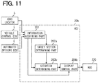
- FIG. 11 is a diagram illustrating an example of the schematic configuration of the HCU
- FIG. 12 is a diagram for explaining a specific example of the target information source display in the display control part
- FIG. 13 is a diagram for explaining a specific example of changing of the target information source display in accordance with an urgency level in the display control part;
- FIG. 14 is a flow chart illustrating an example of the flow of the virtual image display control related process in the HCU
- FIG. 15 is a diagram illustrating an example of the schematic configuration of the vehicle system
- FIG. 16 is a diagram illustrating an example of the schematic configuration of the HCU
- FIG. 17 is a diagram for explaining an example of a method of estimating a road surface range which is visually recognizable by a driver of the host vehicle;
- FIG. 18 is a diagram for explaining an example of limiting of a range of lane guidance display
- FIG. 19 is a flow chart illustrating an example of the flow of the virtual image display control related process in the HCU
- FIG. 20 is a diagram illustrating an example of the schematic configuration of the vehicle system.
- FIG. 21 is a diagram illustrating an example of the schematic configuration of the HCU.
- HUD head-up display
- a projection member such as a front windshield
- a virtual image is displayed in superimposed relation on a front view of a vehicle.
- a technique which causes the HUD to display a virtual image along a shape of a lane scheduled to be followed by a host vehicle in superimposed relation on the lane in a front view and thus allows a driver to recognize the lane scheduled to be followed by the host vehicle and assists the driver.
- the display of the route virtual image may give an odd feeling to the driver and cause the driver to feel annoyed.
- the driver encounters a situation in which a part of the lane scheduled to be followed by the host vehicle which is more distant from the host vehicle is deviated leftward or rightward from the front of a driver seat to look curved.
- the displayed route virtual image may have a significantly large missing portion corresponding to the part of the lane deviated leftward or rightward from the front of the driver seat.
- the driver sees the display of the route virtual image having such a significantly large missing portion, the driver may feel annoyed. Not only while the host vehicle is turning a curve, but also while the gradient of the lane is changing, the same situation may be encountered.
- the display of the route virtual image may give an odd feeling to the driver and cause the driver to feel annoyed.
- the route ahead of the host vehicle has a section in which the gradient of the lane decreases, depending on the degree to which the gradient of the lane decreases, a blind spot which cannot be visually recognized by the driver is formed on a road surface at a descending gradient.
- a vehicle display control device configured to control display performed by a head-up display for a vehicle.
- the head-up display is configured to project an image on a projection member and thus cause a virtual image to be displayed in superimposed relation on a front view of the vehicle.
- the vehicle display control device includes a situation determining part and a display control part.
- the situation determining part determines a host vehicle situation as a road structure of a road on which a host vehicle is running.
- the display control part selectively limits or does not limit a superimposed display of the virtual image with respect to the same target object serving as a target object on which the virtual image is to be displayed in superimposed relation depending on the host vehicle situation determined by the situation determining part.
- Such configuration allows the superimposed display of the virtual image with respect to the same target object on which the virtual image is to be displayed in superimposed relation in the front view to be selectively limited or unlimited based on the host vehicle situation as the road structure of the road on which the host vehicle is running. Consequently, it is possible to limit the superimposed display of the virtual image with respect to the target object in a situation in which a driver may feel annoyed by the road structure of the road on which the host vehicle is running. Accordingly, in a case of a situation in which the superimposed display of the virtual image is conceivably less necessary for the driver, it is possible to limit the superimposed display of the virtual image with respect to the target object. As a result, it is possible to assist the driver by displaying the virtual image in superimposed relation on the front view of the vehicle and also reduce annoyance caused in the driver by displaying the virtual image in superimposed relation.
- a vehicle display control device is configured to control display performed by a head-up display for a vehicle.
- the head-up display is configured to project an image on a projection member and thus cause a virtual image to be displayed in superimposed relation on a front view of the vehicle.
- the vehicle display control device includes a situation determining part and a display control part.
- the situation determining part determines a host vehicle situation, which is at least either a situation in which a target information source as a road sign or a road marking ahead of the host vehicle on a route is less recognizable by a driver or a situation in which the target information source as the road sign or the road marking ahead of the host vehicle on the route is presumed to be overlooked by the driver.
- the display control part does not limit superimposed display of a virtual image representing the target information source on the front view, when the situation determining part determines that the host vehicle situation is either the situation in which the target information source as the road sign or the road marking ahead of the host vehicle on the route is less recognizable by the driver or the situation in which the target information source as the road sign or the road marking ahead of the host vehicle on the road is presumed to be overlooked by the driver.
- the display control part limits the superimposed display of the virtual image representing the target information source on the front view when the situation determining part determines that the host vehicle situation is neither of the situations shown above.
- Such configuration allows the superimposed display of the virtual image with respect to the same target object on which the virtual image is to be displayed in superimposed relation on the front view to be selectively limited or unlimited based on the host vehicle situation, which is either the situation in which the target information source is less recognizable by the driver or the situation in which the target information source is presumed to be overlooked by the driver. Consequently, it is possible to limit the superimposed display of the virtual image with respect to the target object in at least either the situation in which the target information source is recognizable by the driver or the situation in which the target information source is not presumed to be overlooked by the driver.
- a vehicle system 1 shown in FIG. 1 is for use in a vehicle such as an automobile and includes a HMI (Human Machine Interface) system 2 , an ADAS (Advanced Driver Assistance Systems) locator 3 , a periphery monitoring sensor 4 , a vehicle control ECU 5 , an automated driving ECU 6 , and a turn signal switch 7 . It is assumed that the HMI system 2 , the ADAS locator 3 , the periphery monitoring sensor 4 , the vehicle control ECU 5 , the automated driving ECU 6 , and the turn signal switch 7 are connected to, e.g., an in-vehicle LAN.
- a vehicle using the vehicle system 1 is hereinafter referred to as a host vehicle.
- the ADAS locator 3 includes a GNSS (Global Navigation Satellite System) receiver 30 , an inertia sensor 31 , and a map database (hereinafter referred to as map DB) 32 storing map data.
- the GNSS receiver 30 receives positioning signals from a plurality of artificial satellites.
- the inertia sensor 31 includes, e.g., a triaxial gyro sensor and a triaxial acceleration sensor.
- the map DB 32 is a nonvolatile memory and stores map data such as link data, segment data, node data, and road shape data.
- the link data includes individual data items such as a link ID specifying each of links, a link length showing a length of the link, a link orientation, a link travel time, node coordinates of a start point and an end point of the link, and a road attribute.
- the segment data is data for each of segments obtained by dividing the link with shape points and includes a segment ID specifying the segment, a segment length showing a length of the segment, a curvature of the segment, and shape point IDs at the both ends of the segment.
- the node data includes individual data items such as a node ID as a specific number given to each of nodes on a map, node coordinates, a node name, a node type, a connected link ID having the link ID of the link connected to the node, and an intersection type.
- road shape data includes data items such as a longitudinal gradient and a curvature.
- map data three-dimensional map data including data items such as a geographical feature, structures including road signs, and road markings.
- the configuration may also be such that the map data is obtained from outside the host vehicle using an in-vehicle communication module mounted in the host vehicle.
- the ADAS locator 3 combines the positioning signals received by the GNSS receiver 30 and a measurement result from the inertia sensor 31 to sequentially determine a vehicle position of the host vehicle on which the ADAS locator 3 is mounted. Note that the ADAS locator 3 may also be configured to use, in determining the vehicle position, a traveled distance obtained from a pulse signal sequentially output from a wheel speed sensor mounted in the host vehicle. Then, the ADAS locator 3 outputs the determined vehicle position to the in-vehicle LAN. The ADAS locator 3 also reads the map data from the map DB 32 and outputs the map data to the in-vehicle LAN.
- the periphery monitoring sensor 4 detects a stationary object and a mobile object around the host vehicle and detects road markings such as a regulatory marking, a directive marking, and a lane demarcation line.
- the periphery monitoring sensor 4 may also be configured appropriately to use a forward camera 40 which captures an image in a predetermined range ahead of the host vehicle.
- the forward camera 40 may appropriately be configured to be provided in a rearview mirror 11 (see FIG. 2 ) of the host vehicle.
- the forward camera 40 may also be provided in an upper surface of an instrument panel 12 (see FIG. 2 ) of the host vehicle.
- the periphery monitoring sensor 4 may also be configured to use a camera which captures an image in a range other than the range ahead of the host vehicle, a millimeter-wave radar, a sonar, LIDAR (Light Detection and Ranging/Laser Imaging Detection and Ranging), or the like.
- a camera which captures an image in a range other than the range ahead of the host vehicle
- a millimeter-wave radar a sonar
- LIDAR Light Detection and Ranging/Laser Imaging Detection and Ranging
- the vehicle control ECU 5 is an electronic control device which performs acceleration/deceleration control and/or steering control for the host vehicle.
- Examples of the vehicle control ECU 5 include a steering ECU which performs the steering control, and a power unit control ECU and a brake ECU which perform the acceleration/deceleration control.
- the vehicle control ECU 5 acquires respective detection signals output from individual sensors mounted in the host vehicle, such as an accelerator position sensor, a brake pedal force sensor, a steering angle sensor, and a wheel speed sensor, and outputs respective control signals to individual drive control devices such as an electronic control throttle, a brake actuator, and an EPS (Electric Power Steering) motor.
- the vehicle control ECU 5 can also output the detection signals from the individual sensors described above to the in-vehicle LAN.
- the automated driving ECU 6 controls the vehicle control ECU 5 to perform an automated driving function which performs a driving operation in place of the driver.
- the automated driving ECU 6 recognizes an environment in which the host vehicle is running from the vehicle position of the host vehicle and the map data each acquired from the ADAS locator 3 and from a detection result from the periphery monitoring sensor 4 .
- the automated driving ECU 6 recognizes a shape of an object around the host vehicle and a moving state thereof from the detection result from the periphery monitoring sensor 4 or recognizes a shape of a marking around the host vehicle.
- the automated driving ECU 6 combines the vehicle position of the host vehicle with the map data to produce a virtual space as a three-dimensional representation of a real vehicle-running environment.
- the automated driving ECU 6 also plans, based on the recognized vehicle-running environment, driving schedules for causing the host vehicle to perform automated driving using the automated driving function.
- a long/middle-term driving schedule and a short-term driving schedule are planned.
- a route for causing the host vehicle to drive to a set destination is defined.
- a scheduled driving trajectory for implementing driving based on the long/middle-term driving schedule is defined. Specifically, execution of steering for following a lane or changing lanes, acceleration/deceleration for speed adjustment, a crash stop for avoiding a collision is determined based on the short-term driving schedule.
- the turn signal switch 7 is a switch for detecting a turn-on operation performed on a turn signal lever of the host vehicle.
- the turn signal switch 7 outputs, to the in-vehicle LAN, a turn signal based on the operation of the turn signal lever before a right/left turn is made.
- the HMI system 2 includes a HCU (Human Machine Interface Control Unit) 20 , an operation device 21 , and a display device 22 and receives an input operation from the driver of the host vehicle or shows information to the driver of the host vehicle.
- the operation device 21 is a group of switches to be operated by the driver of the host vehicle.
- the operation device 21 is used to perform various settings.
- the operation device 21 includes a steering switch provided in a spoke portion of a steering wheel of the host vehicle.
- a head-up display (HUD) 220 is used as the display device 22 . Referring to FIG. 2 , a description is given herein of the HUD 220 .
- the HUD 220 is provided in the instrument panel 12 of the host vehicle.
- the HUD 220 forms a displayed image based on image data output from the HCU 20 using a projector 221 of such a type as, e.g., liquid-crystal type or scanning type.
- Examples of the displayed image include an image representing a host vehicle state such as a vehicle speed or an operating state of the automated driving function.
- Examples of the displayed image also include an image representing a route scheduled to be followed by the host vehicle and an image representing an information source such as a road sign or a road marking.
- the HUD 220 may also be configured to use an image representing information other than the information mentioned above.
- the HUD 220 projects a displayed image formed by the projector 221 on a projection area already defined in a front windshield 10 as a projection member through an optical system 222 such as, e.g., a concave mirror. It is assumed that the projection area is located, e.g., in front of a driver seat. A light flux of the displayed image reflected by the front windshield 10 toward the vehicle interior is perceived by the driver occupying the driver seat. In addition, a light flux from the front view as a scene present in front of the host vehicle, which is transmitted by the front windshield 10 formed of translucent glass, is also perceived by the driver occupying the driver seat.
- the HUD 220 displays the virtual image 100 in superimposed relation on the front view of the host vehicle to implement so-called AR (Augmented Reality) display.
- the projection member on which the HUD 220 projects the displayed image is not limited to the front windshield 10 and may also be a translucent combiner.
- the HMI system 2 may also be configured such that, in addition to the HUD 220 , a device which displays an image is used as the display device 22 . Examples of the device which displays the image include a combination meter and a CID (Center Information Display).
- the HCU 20 is configured to include, as a main component, a microcomputer including a processor, a volatile memory, a nonvolatile memory, an I/O, and a bus connecting the processor, the volatile memory, the nonvolatile memory, and the I/O.
- the HCU 20 is connected to the HUD 220 and to the in-vehicle LAN.
- the HCU 20 executes a control program stored in the nonvolatile memory to control the display performed by the HUD 220 .
- the HCU 20 corresponds to the vehicle display control device. Note that a configuration of the HCU 20 associated with the control of the display performed by the HUD 220 will be described later in detail.
- the HCU 20 includes, as a functional block, an information acquiring part 201 , a target section determining part 202 , a situation determining part 203 , and a display control part 204 in association with the control of the display performed by the HUD 220 .
- the HCU 20 may also be configured as hardware using one or a plurality of ICs or the like.
- some or all of the functional blocks included in the HCU 20 may also be implemented by a combination of software executed by the processor and a hardware member.
- the information acquiring part 201 acquires information required for the display performed by the HUD 220 .
- Examples of the required information include information items such as the vehicle position and the map data each output from the ADAS locator 3 , respective detection signals from the individual sensors which are output from the vehicle control ECU 5 , the vehicle-running environment recognized by the automated driving ECU 6 , and the driving schedules planned by the automated driving ECU 6 .
- the target section determining part 202 determines whether or not a road on which the host vehicle is running is in a section (hereinafter referred to as target section) as a target on which a virtual image for lane guidance is to be displayed (hereinafter referred to as lane guidance display).
- the lane guidance display shows an inner range of a lane scheduled to be followed in a front view along a shape of the lane.
- the lane guidance display covers a majority of, e.g., equal to or more than half of a lane width of the target lane.
- the following description will be given of a case where the lane guidance display covers a width substantially equal to the lane width of the target lane.
- the lane scheduled to be followed in the front view mentioned herein is the lane scheduled to be followed by the host vehicle according to the driving schedules.
- the target section mentioned herein may be a link-based section, a segment-based section, or a section demarcated on another basis. Examples of the target section include sections in which the host vehicle is required to turn, such as a pre-branch section, a pre-joint section, a section in which the host vehicle is about to turn such as a pre-curve section, and a curved road.
- the target section determining part 202 may appropriately determine whether or not the section corresponding to the vehicle position of the host vehicle is the target section based on the vehicle position and the map data each output from the ADAS locator 3 .
- the section corresponding to the vehicle position of the host vehicle may appropriately be specified by performing, e.g., a map matching process. Note that, when the position of the host vehicle on the road is specified by performing even the map matching process using the ADAS locator 3 , the target section determining part 202 may appropriately be configured to use the position of the host vehicle on the road instead of the vehicle position.
- the curved roads may appropriately be determined as such based on the map data.
- the curved roads may also be determined as such based on a curvature among factors determining a road shape.
- the target section determining part 202 may also determine whether or not the section corresponding to the vehicle position of the host vehicle is the target section based on the vehicle-running environment recognized by the automated driving ECU 6 .
- the situation determining part 203 determines the curvature of the road on which the host vehicle is running.
- the road on which the host vehicle is running may appropriately be in the section corresponding to the vehicle position of the host vehicle.
- the curvature of the road on which the host vehicle is running corresponds to a host vehicle situation.
- the section corresponding to the vehicle position of the host vehicle may appropriately be specified in the same manner as described above.
- the section corresponding to the vehicle position of the host vehicle may be a link-based section, a segment-based section, or a section demarcated on another basis.
- the situation determining part 203 may determine the curvature of the road on which the host vehicle is running from the vehicle-running environment recognized by the automated driving ECU 6 or may also determine the curvature of the road on which the host vehicle is running based on the vehicle position and the map data each output from the ADAS locator 3 .
- the situation determining part 203 also determines whether or not the curvature of the road on which the host vehicle is running is equal to or more than a threshold.
- the threshold mentioned herein may appropriately be a value of the curvature at which the lane guidance display is predicted to be so deviated from the projection area as to presumably give an odd feeling to the driver.
- the threshold may appropriately be estimated by simulation or determined by experimental driving.
- the display control part 204 causes the HUD 220 to perform the lane guidance display showing the inner range of a lane scheduled to be followed in the front view along the shape of the lane.
- the lane scheduled to be followed may appropriately be specified according to the driving schedules planned by the automated driving ECU 6 .
- the display control part 204 may appropriately be configured to perform position and shape adjustment between the lane scheduled to be followed in the front view and the lane guidance display using the vehicle-running environment recognized by the automated driving ECU 6 , camera parameters of the forward camera 40 , or the like.
- the display control part 204 may appropriately be configured to perform drawing for the lane guidance along the shape of the lane scheduled to be followed by approximating the shape of the lane scheduled to be followed with a three-dimensional spline curve, a polynomial expression, or the like.
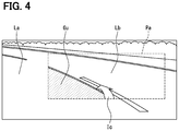
- the display control part 204 prevents the HUD 220 from performing the lane guidance display. This is because, when the host vehicle turns, depending on the magnitude of the curvature of the road on which the host vehicle is running, an issue shown below arises. Specifically, as shown in FIG. 4 , when the host vehicle turns, depending on the magnitude of the curvature of the road on which the host vehicle is running, a situation is encountered in which a part of the lane (see La in FIG.
- the display control part 204 prevents the HUD 220 from performing the lane guidance display.
- the display control part 204 causes a virtual image of an icon (hereinafter referred to as route direction icon) representing a scheduled route direction of the host vehicle to be displayed (see Ic in FIG. 4 ) either in a case where the lane guidance display is allowed to be performed or in a case where the lane guidance display is not allowed to be performed.
- the route direction icon is an image of a type different from that of the lane guidance described above.
- the route direction icon may appropriately be configured to have, e.g., an arrow shape indicating the direction of the scheduled route of the host vehicle.
- the display of the virtual image of the route direction icon is referred to as route direction icon display.
- the display control part 204 preferably causes the virtual image of the route direction icon to be displayed in superimposed relation on the inside of the lane scheduled to be followed in the front view so as to allow the driver to easily and intuitively recognize the scheduled route direction of the host vehicle. Since the lane scheduled to be followed in the front view has at least a portion located in front of the driver seat of the host vehicle, it is preferable to cause the virtual image of the route direction icon to be displayed, by default, in superimposed relation on a center of the projection area located in front of the driver seat in a vehicle width direction and thus displayed on the inside of the lane scheduled to be followed in the front view.
- the display control part 204 shifts a position at which the virtual image of the route direction icon is displayed in a direction in which the host vehicle turns as the curvature of the road on which the host vehicle is running increases.
- the display position of the virtual image of the route direction icon is fixed to the center of the projection area in the vehicle width direction, the following problem arises.
- FIG. 4 when the host vehicle turns, depending on the magnitude of the curvature of the road on which the host vehicle is running, a situation is encountered in which a majority of the projection area (see Pa in FIG. 4 ) in front of the driver seat is occupied by a lane (see Lb in FIG. 4 ) adjacent to the lane scheduled to be followed by the host vehicle.
- the display position of the virtual image of the route direction icon is shifted in the direction in which the host vehicle turns as the curvature of the road on which the host vehicle is running increases. This allows the display position of the virtual image of the route direction icon to more easily fall within the lane scheduled to be followed by the host vehicle and can reduce such feeling of annoyance. It is assumed that the correspondence relationship between the magnitude of the curvature of the road on which the host vehicle is running and an amount of shift of the display position of the virtual image of the route direction icon is determined so as to allow the virtual image of the route direction icon to fall within the lane scheduled to be followed by the host vehicle.
- the display control part 204 shifts the display position of the virtual image of the route direction icon such that the display position of the virtual image of the route direction icon falls within the inner range of the projection area.
- the display control part 204 may be configured appropriately to shift the display position of the virtual image of the route direction icon in the direction in which the host vehicle turns as the curvature of the road on which the host vehicle is running increases until the display position of the virtual image of the route direction icon falls within the inner range of the projection area.
- the display control part 204 stops the display position of the virtual image of the route direction icon at the boundary portion between the inside and the outside the projection area. This can prevent the problem that the partially missing virtual image of the route direction icon is displayed.
- the flow chart of FIG. 5 may appropriately be configured to be started when a power source of the HUD 220 is turned ON and a function of the HUD 220 is turned ON.
- the HUD 220 may appropriately be configured such that the function of the HUD 220 is selectively turned on or off in response to an input operation received by the operation device 21 .
- the HUD 220 may also be configured appropriately such that the power source of the HUD 220 is selectively turned on or off in response to the turning on or off of a switch (hereinafter referred to as power switch) for starting an internal combustion engine or a motor generator of the host vehicle.
- a switch hereinafter referred to as power switch
- the target section determining part 202 determines whether or not the road on which the host vehicle is running is in the target section.
- the virtual image display control related process proceeds to S 2 .
- the target section determining part 202 determines that the road on which the host vehicle is running is not in the target section (NO in S 1 )
- the virtual image display control related process proceeds to S 4 .
- the situation determining part 203 determines whether or not the curvature of the road on which the host vehicle is running is equal to or more than the threshold.
- the situation determining part 203 determines that the curvature is equal to or more than the threshold (YES in S 2 )
- the virtual image display control related process proceeds to S 4 .
- the situation determining part 203 determines that the curvature is less than the threshold (NO in S 2 )
- the virtual image display control related process proceeds to S 3 .
- the situation determining part 203 may also be configured to use a radius of curvature instead of the curvature.
- the situation determining part 203 may appropriately be configured to use, as a threshold, a value of a reciprocal of the radius of curvature.
- the situation determining part 203 may proceed the virtual image display control related process to S 4 when determining that the radius of curvature is equal to or less than the threshold and proceed the virtual image display control related process to S 3 when determining that the radius of curvature is larger than the threshold.
- the display control part 204 causes the HUD 220 to perform the lane guidance display in addition to the route direction icon display, and proceeds the virtual image display control related process to S 5 .
- the display control part 204 causes the HUD 220 to perform the route direction icon display, but does not allow the HUD 220 to perform the lane guidance display, and proceeds the virtual image display control related process to S 5 .
- the display control part 204 shifts the display position of the virtual image of the route direction icon in the direction in which the host vehicle turns as the curvature of the road on which the host vehicle is running increases.
- the display control part 204 shifts, when shifting the position at which the virtual image of the route direction icon is displayed in superimposed relation on the front view, the display position of the virtual image of the route direction icon such that the display position of the virtual image of the route direction icon falls within the projection area.
- FIGS. 6A to 6C a description is given of an example of a transition of the superimposed display of the virtual image responding to the changing of the road on which the host vehicle is running.
- FIG. 6A shows an example of the superimposed display of the virtual image on a straight road.
- FIG. 6B shows an example of the superimposed display of the virtual image before a curve.
- FIG. 6C shows an example of the superimposed display of the virtual image while the host vehicle is turning the curve.
- Pa represents the projection area
- Ic represents the route direction icon display
- Gu represents the guidance display
- Ce represents a region at the center of the projection area in the vehicle width direction.
- the route direction icon display As shown in FIG. 6A , while the host vehicle is running on the straight road, of the route direction icon display (see Ic in FIG. 6A ) and the guidance display (see Gu in FIG. 6B ), only the route direction icon display is superimposed on the front view. On the other hand, when the host vehicle reaches a point immediately before the curve, in addition to the route direction icon display, the guidance display is also superimposed on the front view. Then, while the host vehicle is turning the curve having the curvature equal to or more than the threshold, the guidance display is stopped and, of the route direction icon display and the guidance display, only the route direction icon display is superimposed on the front view.
- the route direction icon display is performed in such a manner as to be shifted from the center (see Ce in FIG. 6C ) of the projection area (see Pa in FIG. 6C ) in the vehicle width direction into the direction in which the host vehicle turns as the curvature of the road on which the host vehicle is running increases.
- the guidance display allows the driver to recognize that a system of the host vehicle can recognize the lane of the curved road and turns in the target section such as a pre-curve section, a pre-joint section, a pre-branch section, or a curve having a curvature less than the threshold and thus allows the driver to feel secure about a system status.
- a system of the host vehicle can recognize the lane of the curved road and turns in the target section such as a pre-curve section, a pre-joint section, a pre-branch section, or a curve having a curvature less than the threshold and thus allows the driver to feel secure about a system status.
- the driver can conceivably feel rather secure, of the route direction icon display and the guidance display, only the route direction icon display is performed in superimposed relation on the front view to be able to reduce the annoyance caused in the driver by excessive information.
- the lane guidance display is stopped to reduce the annoyance caused in the driver by the partially missing lane guidance display. Since the route direction icon display is continued even while the host vehicle is turning the curve having the curvature equal to or more than the threshold, the driver can recognize that the system of the host vehicle turns on a curved road and is thereby allowed to feel secure about the system status.
- the display control part 204 selectively determines, with respect to the lane guidance display showing the inner range of the lane scheduled to be followed in the front view along the shape of the lane, whether or not the superimposed display on the front view is to be stopped based on whether or not the curvature of the road on which the host vehicle is running is equal to or more than the threshold.
- a configuration to be used is not necessarily limited thereto.
- the shape of the guidance display is not limited to such a sheet shape as in the example of the lane guidance display shown in FIGS. 3 and 6A to 6C .
- the shape of the guidance display may also be another shape such as, e.g., a ladder shape or a shape in which a plurality of arrow head portions of arrows are arranged on the route.
- the display control part 204 when the display control part 204 causes the HUD 220 to perform display during the automated driving, the HUD 220 is caused to constantly perform the route direction icon display.
- a configuration to be used is not necessarily limited thereto.
- the display control part 204 causes the HUD 220 to perform the route direction icon display only when the HUD 220 is not caused to perform the lane guidance display. Note that the same applies also to the first modification in which the guidance display is performed instead of the lane guidance display.
- a configuration to be used is not necessarily limited thereto.
- the configuration may appropriately be such that the vehicle system 1 does not include the automated driving ECU 6 , and the recognition of the vehicle-running environment is performed by another ECU, such as the HCU 20 .
- the target section in which the lane guidance display is to be performed is limited, but a configuration to be used is not necessarily limited thereto.
- a configuration in which the target section in which the lane guidance display is to be performed is not limited.
- the configuration may appropriately be such that the HCU 20 does not include the target section determining part 202 . Note that the same applies also to the first modification in which the guidance display is performed instead of the lane guidance display.
- a configuration to be used is not necessarily limited thereto.
- the situation determining part 203 may appropriately be configured to determine the gradient change of the road on which the host vehicle is running.
- the situation determining part 203 may appropriately determine the gradient change of the road on which the host vehicle is running based on the vehicle-running environment recognized by the automated driving ECU 6 or may also determine the gradient change of the road on which the host vehicle is running based on the vehicle position and the map data each output from the ADAS locator 3 .
- the gradient change of the road on which the host vehicle is running corresponds to the host vehicle situation.
- a change rate of a longitudinal gradient of a section subsequent to the section corresponding to the current vehicle position or the like may appropriately be used.
- the situation determining part 203 determines whether or not the gradient change of the road on which the host vehicle is running is equal to or more than a threshold.
- the threshold mentioned herein may appropriately be a value of the gradient change at which the lane guidance display is predicted to be so deviated from the projection area as to presumably give an odd feeling to the driver.
- the threshold may appropriately be estimated by simulation or determined by experimental driving.
- a configuration to be used is not necessarily be limited thereto.
- a configuration hereinafter referred to as a second embodiment
- a target information source as a target road sign or a target road marking ahead of the host vehicle on the route is in a situation in which the target information source is less recognizable by the driver, it is selectively determined whether or not a virtual image representing the target information source is to be displayed in superimposed relation on the front view.
- the vehicle system 1 of the second embodiment 2 is the same as the vehicle system 1 of the first embodiment except that the vehicle system 1 of the second embodiment includes a HCU 20 a , instead of the HCU 20 .
- the HCU 20 a is the same as the HCU 20 of the first embodiment except that a configuration of the HCU 20 a related to the control of the display performed by the HUD 220 is partly different from that of the HCU 20 .
- the second embodiment it may also be possible to use a configuration to be applied to a case where the virtual image representing the target information source is displayed in superimposed relation on the front view during the automated driving.
- the following will describe the configuration on the assumption that the configuration is to be applied to a case where the virtual image representing the target information source is displayed in superimposed relation on the front view during manual driving.
- the second embodiment it may also be possible to use a configuration in which the vehicle system 1 does not include the automated driving ECU 6 , and the recognition of the vehicle-running environment is performed by another ECU such as the HCU 20 a.
- the HCU 20 a includes, as a functional block, the information acquiring part 201 , a target section determining part 202 a , a situation determining part 203 a , a display control part 204 a , and a display condition determining part 205 in association with the control of the display performed by the HUD 220 .
- the HCU 20 a also corresponds to the vehicle display control device.
- the target section determining part 202 a determines whether or not the road on which the host vehicle is running is in a target section in which the target information source is present.
- the target information source can be set to any road sign or to any road marking. Examples of the target information source include a sign which prohibits or specifies a specific traffic method such as a temporary halt sign, a no-parking sign, a no-entry sign, or a maximum speed sign, a sign which represents a permitted behavior, an alert sign, and a guide sign.
- the target section mentioned herein may be a link-based section, a segment-based section, or a section demarcated on another basis.
- the target section determining part 202 a may appropriately determine whether or not the section corresponding to the vehicle position of the host vehicle is in the target section based on the vehicle position and the map data each output from the ADAS locator 3 .
- the presence of the target information source may appropriately be determined using road sign data, road marking data, or the like each included in the three-dimensional map data.
- the situation determining part 203 a determines whether or not the target information source ahead of the host vehicle on the route is in a situation (hereinafter referred to as recognition difficult situation) in which the target information source is less likely to be recognized by the driver. Whether or not the target information source is in the recognition difficult situation corresponds to the host vehicle situation. For example, when the periphery monitoring sensor 4 has not successfully detected the target information source at a position ahead of the host vehicle on the route at which, according to the map data, the target information source is presumed to be present, the situation determining part 203 a determines that the target information source is in the recognition difficult situation.
- the situation determining part 203 a determines that the target information source is not in the recognition difficult situation.
- whether or not the periphery monitoring sensor 4 has successfully detected the target information source may appropriately be determined depending on whether or not the target information source has successfully been recognized at a position in the vehicle-running environment recognized by the automated driving ECU 6 at which, according to the map data, the target information source is presumed to be present.
- Examples of a case where the recognition difficult situation is encountered include cases as shown below.
- a road marking as the target information source is partly missing or covered with snow or the like and is less recognizable.
- a road sign as the target information source is partly missing or hidden by a parked vehicle, a vehicle ahead, a geographical feature, or a structure and is less recognizable.
- the display condition determining part 205 determines, when the situation determining part 203 a determines that the target information source is in the recognition difficult situation, whether or not a condition for displaying the virtual image representing the target information source determined to be in the recognition difficult state is satisfied.
- Examples of the display condition include a distance between the target information source and the host vehicle which is less than a set value.
- the set value may appropriately be an arbitrarily settable distance which is presumed to allow the host vehicle to behave in accordance with what is represented by the target information source before the host vehicle reaches the target information source.
- the target information source shows a regulation which prohibits or specifies a specific traffic method such as no parking
- a sign of not following the regulation shown by the target information source, which is shown by the host vehicle may also be used as the display condition.
- the sign of not following the regulation shown by the target information source may appropriately be detected from the running state of the host vehicle.
- the sign of not following the regulation shown by the target information source may appropriately be detected based on detection signals from the individual sensors which are output from the vehicle control ECU 5 or the like.
- the target information source is a sign showing no parking, based on a detection signal from the wheel speed sensor, the speed of the host vehicle which becomes equal to or less than a predetermined speed may also be detected as the sign of not following the regulation.
- the turning ON of the hazard switch may also be detected as the sign of not following the regulation.
- the target information source is the sign or a marking showing the maximum speed, based on the detection signal from the wheel speed sensor, the speed of the host vehicle exceeding the maximum speed regulated by the target information source may appropriately be detected as the sign of not following the regulation.
- the display control part 204 a causes the HUD 220 to display the virtual image representing the target information source in superimposed relation on the front view.
- the display of the virtual image representing the target information source is hereinafter referred to as target information source display.
- the display control part 204 a prevents the HUD 220 from performing the target information source display.
- the display control part 204 a may also be configured to cause the HUD 220 to perform the target information source display in superimposed relation on a position (hereinafter referred to a target present position) at which the target information source determined to be in the recognition difficult situation should be present in the front view.
- the display control part 204 a may also be configured to selectively determine whether the target information source display is to be performed in superimposed relation on the target present position or on a position other than the target present position depending on a type of the recognition difficult situation.
- the display control part 204 a may appropriately be configured to cause the HUD 220 to perform the target information source display in superimposed relation on a position other than the target present position.
- the display control part 204 a may appropriately be configured to cause the HUD 220 to perform the target information source display in superimposed relation on the target present position.
- the display control part 204 a may appropriately cause the HUD 220 to perform the target information source display in superimposed relation on a position at which the marking is originally present in the front view.
- a virtual image of an image of the marking showing the direction of travel may appropriately be displayed.
- the display control part 204 a may appropriately cause the HUD 220 to perform the target information source display (see ViNP) in superimposed relation on a position other than the position at which the sign showing no parking is originally present in the front view.
- the virtual image (see ViNP) of an image of the sign showing no parking may appropriately be displayed at a position away from the parked vehicle.
- the display control part 204 a may also be configured to cause a virtual image (see NPAr) representing a no-parking area to be displayed, in addition to the virtual image of the image of the sign showing no parking, in superimposed relation on an area corresponding to the no-parking area in the front view.
- a virtual image (see NPAr) representing a no-parking area
- the no-parking area may appropriately be allowed to be specified based on the map data.
- the virtual image representing the no-parking area preferably has a color, a pattern, or the like different from that of the lane guidance display.
- the virtual image representing the no-parking area may appropriately have a pattern or the like similar to that of a zebra zone.
- the display control part 204 a may also be configured to cause the HUD 220 to display a three-dimensional object as the virtual image.
- the display control part 204 a may appropriately cause the HUD 220 to perform the target information source display (see ViSP) in superimposed relation on a position other than the position at which the sign showing a temporary halt is originally present in the front view.
- the virtual image (see ViSP) of an image of the sign showing a temporary halt may appropriately be displayed.
- the display control part 204 a may also be configured to cause the HUD 220 to perform the lane guidance display (see Gu) described above in superimposed relation on the lane scheduled to be followed in the front view, in addition to displaying the virtual image of the image of the sign showing a temporary halt.
- the lane scheduled to be followed may appropriately be the same as the lane in which the host vehicle is running.
- the virtual image display control related process may appropriately be configured to be started when the power supply of the HUD 220 is turned on and the function of the HUD 220 is turned on.
- the target section determining part 202 a determines whether or not the road on which the host vehicle is running is in the target section.
- the target section determining part 202 a determines that the road on which the host vehicle is running is in the target section (YES in S 21 )
- the virtual image display control related process proceeds to S 22 .
- the target section determining part 202 a determines that the road on which the host vehicle is running is not in the target section (NO in S 21 )
- the virtual image display control related process proceeds to S 25 .
- the situation determining part 203 a determines whether or not the target information source ahead of the host vehicle on the route is in the recognition difficult situation in which the target information source is less recognizable by the driver.
- the virtual image display control related process proceeds to S 23 .
- the situation determining part 203 a determines that the target information source is not in the recognition difficult situation (NO in S 22 )
- the virtual image display control related process proceeds to S 25 .
- the display condition determining part 205 determines whether or not the condition for displaying the virtual image representing the target information source determined to be in the recognition difficult situation is satisfied.
- the virtual image display control related process proceeds to S 24 .
- the display condition determining part 205 determines that the display condition is not satisfied, the virtual image display control related process proceeds to S 25 .
- the display control part 204 a causes the HUD 220 to perform the target information source display in superimposed relation on the front view, and the virtual image display control related process proceeds to S 25 .
- the target information source display may appropriately be ended when the host vehicle has passed through the position at which the target information source is present or ended when the display condition determining part 205 determines that the display condition is not satisfied.
- the virtual image representing the target information source is not constantly displayed, but is displayed when it is determined that the target information source ahead of the host vehicle on the route is in the situation in which the target information source is less recognizable by the driver.
- This allows the virtual image representing the target information source to be displayed at a time when the display of the virtual image representing the target information source is presumed to be useful to the driver and also allows a reduction in the annoyance felt by the driver compared to a case where the target information source is allowed to be constantly displayed.
- the approach to the target information source as the display condition it is possible to restrict the virtual image representing the target information source from being displayed at a time when the display of the virtual image is less likely to be useful to the driver. This can further reduce the annoyance felt by the driver.
- the sign of not following the regulation shown by the target information source as the display condition it is possible to restrict the virtual image of the target information source from being displayed though the host vehicle is following the regulation shown by the target information source. This can further reduce the annoyance felt by the driver.
- the display control part 204 a when the display condition determining part 205 determines that the display condition is satisfied, the display control part 204 a causes the HUD 220 to display the virtual image representing the target information source in superimposed relation on the front view, but a configuration to be used is not limited thereto.
- the HCU 20 a does not include the display condition determining part 205 and, when the situation determining part 203 a determines that the target information source ahead of the host vehicle on the route is in the recognition difficult situation in which the target information source is less recognizable by the driver, the display control part 204 a causes the HUD 220 to display the virtual image representing the target information source in superimposed relation on the front view.
- a configuration in which, depending on whether or not the target information source as a target road sign or a target road marking ahead of the host vehicle on the route is in a situation in which the target information source is presumed to be overlooked by the driver, it is selectively determined whether or not a virtual image representing the target information source is to be displayed in superimposed relation on the front view.
- the vehicle system 1 of the third embodiment is the same as the vehicle system 1 of the first embodiment except that the vehicle system 1 of the third embodiment includes a HCU 20 b instead of the HCU 20 .
- the HCU 20 b is the same as the HCU 20 of the first embodiment except that a configuration of the HCU 20 b associated with the control of the display performed by the HUD 220 is partly different from that of the HCU 20 .
- the third embodiment it may also be possible to use a configuration in which the vehicle system 1 does not include the automated driving ECU 6 , and the recognition of the vehicle-running environment is performed by another ECU such as the HCU 20 b.
- the HCU 20 b includes, as a functional block, the information acquiring part 201 , a target section determining part 202 a , a situation determining part 203 b , and a display control part 204 b in association with the control of the display performed by the HUD 220 .
- the HCU 20 b also corresponds to the vehicle display control device.
- the target section determining part 202 a determines whether or not the road on which the host vehicle is running is in the target section in which the target information source is present.
- the target information source can be set to any sign or to any marking showing a regulation. Examples of the target information source include a road sign, a road marking, or the like which prohibits or specifies a specific traffic method such as a temporary halt, no parking, no entry, or a maximum speed.
- the situation determining part 203 b determines whether or not the target information source ahead of the host vehicle on the route is in a situation (hereinafter referred to as oversight situation) in which the target information source is presumed to be overlooked by the driver. Whether or not the target information source is in the oversight situation corresponds to the host vehicle situation. For example, when the host vehicle shows the sign of not following the regulation shown by the target information source, the situation determining part 203 b determines that the target information source is in the oversight situation. On the other hand, when the host vehicle does not show the sign of not following the regulation shown by the target information source, the situation determining part 203 b determines that the target information source is not in the oversight situation.
- the sign of not following the regulation shown by the target information source may appropriately be detected from the running state of the host vehicle.
- the sign of not following the regulation shown by the target information source may appropriately be detected.
- the target information source is a sign showing no parking
- the speed of the host vehicle which becomes equal to or less than the predetermined speed may also be detected as the sign of not following the regulation.
- the turning ON of the hazard switch may also be detected as the sign of not following the regulation.
- the target information source is a sign or a marking showing a maximum speed
- the speed of the host vehicle exceeding the maximum speed regulated by the target information source may appropriately be detected as the sign of not following the regulation.
- a turn signal from the turn signal switch 7 which shows a change of direction into a road provided with the target information source may appropriately be detected as the sign of not following the regulation.
- the situation determining part 203 b may also determine whether or not the target information source is in the oversight situation using the following configuration. Specifically, the situation determining part 203 b may appropriately detect an eye direction of the driver from the face image and determine, when a time period during which the driver is looking at the target information source is less than a set time period, that the target information source is in the situation in which the target information source is presumed to be overlooked by the driver. It may also be possible to use a configuration in which e.g., a DSM (Driver Status Monitor) other than the HCU 20 b detects the eye direction of the driver from the face image.
- DSM Driver Status Monitor
- the display control part 204 b causes the HUD 220 to display the virtual image representing the target information source in superimposed relation on the front view.
- the display of the virtual image representing the target information source is referred to as the target information source display.
- the display control part 204 b prevents the HUD 220 from performing the target information source display.
- the display control part 204 b may also be configured to cause the HUD 220 to perform the target information source display in superimposed relation on a position at which the target information source is present in the front view.
- the target information source display is preferably performed in superimposed relation on a position other than the position at which the target information source is present in the front view.
- the display control part 204 b changes a display mode in which the virtual image of the target information source is displayed in superimposed relation on the front view based on a level of urgency of causing the host vehicle to follow the regulation shown by the target information source.
- the display control part 204 b may be configured appropriately to handle a target information source showing a regulation related to a place such that, as a distance to the target information source is shorter, the regulation shown by the target information source has a higher level of urgency.
- the display control part 204 b may also be configured appropriately to handle a target information source showing a regulation related to a maximum speed such that, as a gap between the speed of the host vehicle and the maximum speed regulated by the target information source tends to be larger, the regulation shown by the target information source has a higher level of urgency.
- the display control part 204 b may appropriately cause the HUD 220 to perform the target information source display (see ViNT in FIG. 12 ) in superimposed relation on a road in the front view into which entry is prohibited.
- the virtual image see ViNT in FIG. 12
- the image of the sign showing no entry may appropriately be displayed.
- the display control part 204 b may also be configured to cause the HUD 220 to display, in addition to the virtual image of the image of the sign showing no entry, a virtual image (see NTAr in FIG. 12 ) representing a no-entry area in superimposed relation on an area corresponding to the road in the front view into which entry is prohibited.
- the virtual image representing the no-entry area preferably has a color, a pattern, or the like different from that of the lane guidance display.
- the virtual image representing the no-entry area may appropriately have a pattern or the like similar to that of a zebra zone.
- the display control part 204 b may also be configured to cause the HUD 220 to display a three-dimensional object as the virtual image.
- a virtual image of an image of the sign showing the maximum speed may appropriately be displayed in superimposed relation on the front view.
- the display mode may appropriately be changed based on a level of urgency of causing the host vehicle to follow the regulation shown by the target information source.
- the threshold mentioned herein is an arbitrarily settable value.
- the display control part 204 b fades in the target information source display (see J in FIG. 13 ) such that the driver is less likely to feel annoyed. Subsequently, when the host vehicle shifts from the state with the speed limit exceedance to the state without the speed limit exceedance, to protect the driver from incidentally seeing a sudden display change and feeling annoyed, the display control part 204 b fades out the target information source display (see K in FIG. 13 ). On the other hand, when the speed limit exceedance is on the “HIGH” level, the possibility is high that the driver has overlooked the sign showing the maximum speed.
- the display control part 204 b gives priority to causing the driver to notice the sign and causes the target information source display to blink (see L in FIG. 13 ).
- the display control part 204 b gives priority to causing the driver to notice the sign and causes the target information source display to blink (see L in FIG. 13 ).
- the virtual image display control related process may appropriately be configured to be started when the power source of the HUD 220 is turned on and the function of the HUD 220 is turned on.
- the target section determining part 202 a determines whether or not the road on which the host vehicle is running is in the target section.
- the target section determining part 202 a determines that the road on which the host vehicle is running is in the target section (YES in S 41 )
- the virtual image display control related process proceeds to S 42 .
- the target section determining part 202 a determines that the road on which the host vehicle is running is not in the target section (NO in S 41 )
- the virtual image display control related process proceeds to S 44 .
- the situation determining part 203 b determines whether or not the target information source ahead of the host vehicle on the route is in the oversight situation in which the target information source is presumed to be overlooked by the driver.
- the virtual image display control related process proceeds to S 43 .
- the virtual image display control related process proceeds to S 44 .
- the display control part 204 b causes the HUD 220 to perform the target information source display in superimposed relation on the front view, and the virtual image display control related process proceeds to S 44 .
- the target information source display may appropriately be ended when a time period elapsed from the start of the target information source display reaches a set time period or ended when the sign of not following the regulation shown by the target information source is no longer detected.
- the virtual image representing the target information source is not constantly displayed, but is displayed when it is determined that the target information source ahead of the host vehicle on the route is in the situation in which the target information source is presumed to be overlooked by the driver.
- This allows the virtual image representing the target information source to be displayed at a time when the display of the virtual image representing the target information source is presumed to be useful to the driver and also allows a reduction in the annoyance felt by the driver compared to the case where the target information source is allowed to be constantly displayed.
- Each of the second and third modifications has shown the configuration which limits the target section in which the target information source display is to be performed.
- a configuration to be used is not necessarily limited thereto.
- the HCU 20 a or 20 b may appropriately be configured to cause the situation determining part 203 a or 203 b to sequentially make determination in the virtual image display control related process.
- the configuration which limits the superimposed display of the virtual image on the front view such as the lane guidance display or the target information source display
- the configuration is shown which limits the superimposed display by preventing the superimposed display from being performed.
- a configuration to be used is not necessarily be limited thereto.
- the fifth modification described above has shown the configuration in which, depending on whether or not a gradient change of the road on which the host vehicle is running is equal to or more than a gradient change value at which the lane guidance display is predicted to be so deviated from the projection area as to presumably give an odd feeling to the driver, it is selectively determined whether or not the superimposed display on the front view is to be stopped.
- a configuration to be used is not necessarily limited thereto.
- a configuration in which, e.g., depending on whether or not the gradient change of the road on which the host vehicle is running is equal to or more than a gradient change value which is presumed to form a blind spot visually unrecognizable by the driver on an anterior road surface of the road on which the host vehicle is running, it is selectively determined whether or not the superimposed display on the front view, such as the lane guidance, is to be stopped.
- a gradient change value which is presumed to form a blind spot visually unrecognizable by the driver on an anterior road surface of the road on which the host vehicle is running
- a vehicle system 1 c of the fourth embodiment is the same as the vehicle system 1 of the first embodiment except that the vehicle system 1 c includes a HMI system 2 c , instead of the HMI system 2 , and includes a navigation device 8 .
- the HMI system 2 c includes a HCU 20 c , the operation device 21 , the display device 22 , and a DSM (Driver Status Monitor) 23 .
- the HMI system 2 c is the same as the HMI system 2 of the first embodiment except that the HMI system 2 c includes the HCU 20 c , instead of the HCU 20 , and includes the DSM 23 .
- the DSM 23 includes a near-infrared light source, a near-infrared camera, a control unit which controls the near-infrared light source and the near-infrared camera, and the like.
- the DSM 23 is disposed in, e.g., an upper surface of the instrument panel, while being in a position in which the near-infrared camera faces the driver seat of the host vehicle.
- the DSM 23 causes the near-infrared camera to photograph a head portion of the driver illuminated with near-infrared light from the near-infrared light source.
- An image captured by the near-infrared camera is subjected to image analysis performed by the control unit.
- the control unit detects eyes in the captured image by an image recognition process and specifies an eye point based on the positions of the detected eyes.
- the eye point is a position of each of the eyes of the driver occupying the driver seat.
- the control unit may appropriately be configured to specify the eye point as, e.g., coordinates in a three-dimensional space using, as an origin, the vehicle position of the host vehicle located by the ADAS locator 3 .
- the control unit may appropriately be configured to specify the coordinates of the eye point based on a correspondence relationship between a position defined in advance in the image captured by the near-infrared camera and the position in the three-dimensional space.
- the DSM 23 may also be configured to detect the eye direction of the driver.
- the DSM 23 may appropriately be configured to detect the eye direction of the driver as follows.
- the control unit detects portions of a face such as a facial contour, the eyes, a nose, and a mouth in the captured image by the image recognition process to detect a face orientation of the driver based on relative positional relationships among the individual portions.
- the control unit also detects pupils and corneal reflexes in the captured image by the image recognition process and detects the eye direction based on the detected face orientation and on a positional relationship between the detected pupils and the detected corneal reflexes.
- the navigation device 8 includes a navigation map DB 80 , retrieves a route satisfying a condition such as giving priority to a time period required to reach a set destination or giving priority to a distance to the set destination, and gives routing assistance in accordance with the retrieved route.
- the navigation map DB 80 may appropriately be a nonvolatile memory storing map data such as link data, segment data, node data, and road shapes.
- the navigation map DB 80 When the navigation map DB 80 is used, it is appropriate to use a configuration in which, e.g., the map DB 32 of the ADAS locator 3 does not store the data stored in the navigation map DB 80 such as the link data, the segment data, the node data, and the road shapes, but stores a three-dimensional map including the road shapes and a group of characteristic feature points of structures. It may also be possible to use a configuration in which, for the long/middle-term driving schedule in the automated driving ECU 6 , the route retrieved by the navigation device 8 is used. Note that it may also be possible to apply a configuration including the navigation device 8 to each of the first to third embodiments.
- the HCU 20 c includes, as a functional block, an information acquiring part 201 c , a situation determining part 203 c , a display control part 204 c , and a visually recognizable range estimating part 206 in association with the control of the display performed by the HUD 220 .
- the HCU 20 c also corresponds to the vehicle display control device.
- the HCU 20 c is the same as the HCU 20 of the first embodiment except that the HCU 20 c does not include the target section determining part 202 , includes the visually recognizable range estimating part 206 , and includes the information acquiring part 201 c , the situation determining part 203 c , and the display control part 204 c instead of the information acquiring part 201 , the situation determining part 203 , and the display control part 204 .
- the information acquiring part 201 c is the same as the information acquiring part 201 of the first embodiment except that the information acquiring part 201 c acquires the map data and the route information each output from the navigation device 8 .
- the situation determining part 203 c determines a gradient change of a longitudinal gradient of the road on which the host vehicle is running ahead of the host vehicle.
- the road on which the host vehicle is running ahead of the host vehicle may appropriately be in, e.g., a section subsequent to the section corresponding to the current vehicle position.
- the section may be a link-based section, a segment-based section, or a section demarcated on another basis.
- the situation determining part 203 c may determine the gradient change ahead of the host vehicle from the vehicle-running environment recognized by the automated driving ECU 6 or may also determine the gradient change ahead of the host vehicle from the vehicle position and the map data each output from the ADAS locator 3 , the navigation device 8 , and the like.
- the situation determining part 203 c determines whether or not a gradient decrease rate ahead of the host vehicle as the gradient change ahead of the host vehicle is equal to or more than a threshold.
- the gradient decrease rate ahead of the host vehicle corresponds to the host vehicle situation. It is assumed herein that an ascending gradient value is positive, a descending gradient value is negative, and a horizontal gradient value is zero.
- the threshold mentioned herein may appropriately be a value of the gradient decrease rate which is presumed to form the blind spot visually unrecognizable by the driver on the anterior road surface of the road on which the host vehicle is running.
- the threshold may appropriately be estimated by simulation or determined by experimental driving.
- a situation in which a gradient change forms the blind spot visually unrecognizable by the driver on the anterior road surface of the road on which the host vehicle is running indicates a situation in which, e.g., while the host vehicle is driving up a hill, the road surface ahead of a top of the hill is hidden and unseen from the driver or the like.
- the visually recognizable range estimating part 206 estimates the range of the road surface ahead of the host vehicle which is visually recognizable by the driver of the host vehicle. Specifically, based on the eye point of the driver of the host vehicle, which is acquired from the DSM 23 , and on a road structure of the road on which the host vehicle is running, which is acquired by the information acquiring part 201 c , the range of the road surface visually recognizable by the driver of the host vehicle is estimated.
- the road structure of the road on which the host vehicle is running, which is acquired by the information acquiring part 201 c may appropriately be, e.g., a road structure represented by a three-dimensional map.
- the visually recognizable range estimating part 206 replaces the coordinates of the eye point of the driver with a position on the three-dimensional map, extends a straight line from the coordinates of the eye point on the three-dimensional map in the eye direction of the driver, and assumes that a point at which the extended straight line crosses the road surface is a vanishing point (Vp in FIG. 17 ).
- the visually recognizable range estimating part 206 estimates the road surface extending from the host vehicle to the vanishing point to be the range of the road surface visually recognizable by the driver of the host vehicle. Note that the road surface beyond the vanishing point is estimated to be outside the range of the road surface visually recognizable by the driver of the host vehicle even when the road surface beyond the vanishing point is in a range (Va in FIG. 17 ) which is not upwardly or downwardly deviated from the projection area in which the displayed image is projected.
- the display control part 204 c causes the HUD 220 to perform the lane guidance display showing the inner range of the lane scheduled to be followed in the front view along the shape of the lane, similarly to the display control part 204 of the first embodiment.
- the lane scheduled to be followed may appropriately be specified according to the route suggested by the navigation device 8 .
- the display control part 204 c limits the lane guidance display on the front view. Specifically, when the situation determining part 203 c determines that the gradient decrease rate ahead of the host vehicle is equal to or more than the threshold, the display control part 204 c limits a range of the lane guidance display to within the range estimated by the visually recognizable range estimating part 206 to be the range of the road surface visually recognizable by the driver of the host vehicle. A description will be given thereof with reference to FIG. 18 .
- the display control part 204 c controls the lane guidance display including the range (Pr in FIG.
- the display control part 204 c prevents the lane guidance display on the road surface outside the range estimated to be the range of the road surface visually recognizable by the driver even when the lane guidance display thereon is not upwardly or downwardly deviated from the projection area.
- the fourth embodiment when it is determined that the gradient decrease rate ahead of the host vehicle is equal to or more than the threshold, the range of the lane guidance display is limited to within the range estimated to be the range of the road surface visually recognizable by the driver to be able to reduce such annoyance.
- the range of the road surface visually recognizable by the driver of the host vehicle is estimated by determining the vanishing point.
- a configuration to be used is not necessarily limited thereto.
- the hidden surface removing treatment it is appropriate to use the eye point as a specific point of view, obtain, from all the pixels in the lane guidance display, a hidden surface unseen from the eye point in accordance with, e.g., a Z-buffer method (Z-buffer algorithm), and thus estimate the range of the road surface visually recognizable by the driver of the host vehicle.
- Z-buffer algorithm Z-buffer algorithm
- the display control part 204 c may also be configured to cause the virtual image of the route direction icon showing the direction of the route scheduled to be followed by the host vehicle either in a case where the lane guidance display is allowed to be performed or in a case where the lane guidance display is not allowed to be performed.
- the direction of the route scheduled to be followed by the host vehicle may appropriately be specified according to the route suggested by the navigation device 8 , the running schedules planned by the automated driving ECU 6 , or the like.
- the virtual image display control related process may appropriately be configured to be started when the power source of the HUD 220 is turned on and the function of the HUD 220 is turned on.
- the situation determining part 203 c determines whether or not the gradient decrease rate ahead of the host vehicle is equal to or more than the threshold.
- the virtual image display control related process proceeds to S 62 .
- the situation determining part 203 c determines that the gradient decrease rate is less than the threshold (NO in S 61 )
- the virtual image display control related process proceeds to S 64 .
- the visually recognizable range estimating part 206 estimates the range of the road surface ahead of the host vehicle which is visually recognizable by the driver of the vehicle.
- the display control part 204 c causes the HUD 220 to limit the range of the lane guidance display to within the range of the road surface estimated by the visually recognizable range estimating part 206 to be visually recognizable by the driver of the host vehicle and perform the lane guidance display, and the virtual image display control related process proceeds to S 65 .
- the display control part 204 c causes the HUD 220 to perform the lane guidance display without the limit described above, and the virtual image display control related process proceeds to S 65 .
- S 65 when it is time to end the virtual image display control related process (YES in S 65 ), the virtual image display control related process is ended. On the other hand, when it is not time to end the virtual image display control related process (NO in S 65 ), the virtual image display control related process returns to S 61 to be repeated. Examples of the time to end the virtual image display control related process include a time when the power switch of the host vehicle is turned off and a time when the function of the HUD 220 is turned off.
- the range of the lane guidance display is limited to within the range estimated by the visually recognizable range estimating part 206 to be the range of the road surface visually recognizable by the driver of the host vehicle.
- the eye point of the driver of the host vehicle is specified by the DSM 23 .
- a configuration to be used is not necessarily limited thereto.
- the following will describe a case using the body height as the profile of the driver.
- correspondence relationships obtained by associating representative values of the eye point with body heights are stored.
- representative values mentioned herein a mode value, an average value, an intermediate value, and the like can be used. It is appropriate to specify, based on the correspondence relationships, the eye point in accordance with the body height of the driver received from the driver via the operation device 21 or the like and estimate the specified eye point to be the eye point of the driver.
- the range of the lane guidance display is limited to within the range estimated by the visually recognizable range estimating part 206 to be the range of the road surface visually recognizable by the driver of the host vehicle.
- a configuration to be used is not necessarily limited thereto.
- a vehicle system 1 d of the fifth embodiment is the same as the vehicle system 1 c of the fourth embodiment except that the vehicle system 1 d includes a HMI system 2 d , instead of the HMI system 2 c .
- the HMI system 2 d includes a HCU 20 d , the operation device 21 , and the display device 22 .
- the HMI system 2 d is the same as the HMI system 2 c of the fourth embodiment except that the HMI system 2 d includes the HCU 20 d , instead of the HCU 20 c , and does not include the DSM 23 .
- the HCU 20 d includes, as a functional block, the information acquiring part 201 c , the situation determining part 203 c , and a display control part 204 d in association with the control of the display performed by the HUD 220 .
- the HCU 20 d also corresponds to the vehicle display control device.
- the HCU 20 d is the same as the HCU 20 c of the fourth embodiment except that the HCU 20 d does not include the visually recognizable range estimating part 206 and includes the display control part 204 d instead of the display control part 204 c.
- the display control part 204 d causes the HUD 220 to perform the lane guidance display showing the inner range of the lane scheduled to be followed in the front view along the shape of the lane, similarly to the display control part 204 c of the fourth embodiment.
- the display control part 204 d prevents the HUD 220 from performing the lane guidance display on the front view.
- the display control part 204 d may appropriately be configured to cause the virtual image of the route direction icon showing the direction of the route scheduled to be followed by the host vehicle either in a case where the lane guidance display is allowed to be performed or in a case where the lane guidance display is not allowed to be performed, in the same manner as described in the fourth embodiment.
- the route direction icon display is continued. This allows the driver to recognize that the system of the host vehicle is running in the scheduled route direction and feel secure about the system status.
- the route direction icon display is applied also to a case where the HUD 220 is caused to perform display during manual driving. In this case, even when the gradient decrease rate ahead of the host vehicle is equal to or more than the threshold and the lane guidance display is not allowed to be performed, the route direction icon display is continued. This allows the driver to recognize that the system of the host vehicle is operating and feel secure about the system status.
- the gradient decrease rate ahead of the host vehicle is equal to or more than the threshold, by preventing the lane guidance display from being performed, it is possible to reduce the annoyance felt by the driver due to the lane guidance display performed with respect even to the road surface corresponding to the blind spot.
- the display control part 204 c or 204 d selectively determines, with respect to the lane guidance display showing the inner range of the lane scheduled to be followed in the front view along the shape of the lane, whether or not the superimposed display on the front view is to be limited based on whether or not the gradient decrease rate ahead of the host vehicle is equal to or more than the threshold.
- a configuration to be used is not necessarily limited thereto.
- the HUD 220 when the display control part 204 c or 204 d causes the HUD 220 to perform display during the automated driving, the HUD 220 is caused to constantly perform the route direction icon display.
- a configuration to be used is not necessarily limited thereto.
- the display control part 204 c or 204 d causes the HUD 220 to perform the route direction icon display only when the lane guidance display is not allowed to be performed. Note that the same applies also to the ninth modification in which the guidance display is performed instead of the lane guidance display.
- a configuration to be used is not necessarily limited thereto.
- the configuration may also be possible to use a configuration to be applied to a case where the host vehicle is manually driven.
- the configuration may also be such that the host vehicle does not have an automated driving function.
- the configuration may appropriately be such that the vehicle system 1 c or 1 d does not include the automated driving ECU 6 , and the recognition of the vehicle-running environment is performed by another ECU or performed based on map data of the route suggested by the navigation device 8 .
- the target section in which the lane guidance display is to be performed is not limited, but a configuration to be used is not necessarily limited thereto.
- a configuration to be used is not necessarily limited thereto.
- the configuration which limits the superimposed display of the virtual image on the front view such as the lane guidance display
- the configuration is shown which limits the superimposed display by preventing the superimposed display from being performed.
- a configuration to be used is not necessarily limited thereto.
- the display control part 204 , 204 a , 204 b , or 204 c may also be configured to cause the HUD 220 to display a virtual image representing navigation information such as information showing the running condition of the host vehicle such as a vehicle speed or engine revolutions, information showing an operating state of the automated driving function, routing assistance information, or traffic jam information.
- navigation information such as information showing the running condition of the host vehicle such as a vehicle speed or engine revolutions, information showing an operating state of the automated driving function, routing assistance information, or traffic jam information.
Landscapes
- Engineering & Computer Science (AREA)
- Mechanical Engineering (AREA)
- Transportation (AREA)
- Automation & Control Theory (AREA)
- Chemical & Material Sciences (AREA)
- Combustion & Propulsion (AREA)
- Physics & Mathematics (AREA)
- Computer Hardware Design (AREA)
- General Physics & Mathematics (AREA)
- Theoretical Computer Science (AREA)
- Human Computer Interaction (AREA)
- Mathematical Physics (AREA)
- Instrument Panels (AREA)
- Traffic Control Systems (AREA)
Abstract
Description
Claims (14)
Applications Claiming Priority (7)
| Application Number | Priority Date | Filing Date | Title |
|---|---|---|---|
| JPJP2017-021509 | 2017-02-08 | ||
| JP2017-021509 | 2017-02-08 | ||
| JP2017021509 | 2017-02-08 | ||
| JPJP2017-243498 | 2017-12-20 | ||
| JP2017243498A JP6699646B2 (en) | 2017-02-08 | 2017-12-20 | Vehicle display control device |
| JP2017-243498 | 2017-12-20 | ||
| PCT/JP2018/001849 WO2018147066A1 (en) | 2017-02-08 | 2018-01-23 | Display control apparatus for vehicles |
Related Parent Applications (1)
| Application Number | Title | Priority Date | Filing Date |
|---|---|---|---|
| PCT/JP2018/001849 Continuation WO2018147066A1 (en) | 2017-02-08 | 2018-01-23 | Display control apparatus for vehicles |
Publications (2)
| Publication Number | Publication Date |
|---|---|
| US20190359228A1 US20190359228A1 (en) | 2019-11-28 |
| US11220274B2 true US11220274B2 (en) | 2022-01-11 |
Family
ID=63107351
Family Applications (1)
| Application Number | Title | Priority Date | Filing Date |
|---|---|---|---|
| US16/532,627 Active 2038-08-22 US11220274B2 (en) | 2017-02-08 | 2019-08-06 | Vehicle display control device |
Country Status (2)
| Country | Link |
|---|---|
| US (1) | US11220274B2 (en) |
| WO (1) | WO2018147066A1 (en) |
Families Citing this family (21)
| Publication number | Priority date | Publication date | Assignee | Title |
|---|---|---|---|---|
| JP6726674B2 (en) * | 2015-10-15 | 2020-07-22 | マクセル株式会社 | Information display device |
| JP6809890B2 (en) * | 2016-12-15 | 2021-01-06 | 日立オートモティブシステムズ株式会社 | Vehicle control device |
| KR102547823B1 (en) * | 2017-12-13 | 2023-06-26 | 삼성전자주식회사 | Method and device to visualize content |
| US11506906B2 (en) | 2018-10-23 | 2022-11-22 | Maxell, Ltd. | Head-up display system |
| US11142196B2 (en) * | 2019-02-03 | 2021-10-12 | Denso International America, Inc. | Lane detection method and system for a vehicle |
| DE102019202580A1 (en) * | 2019-02-26 | 2020-08-27 | Volkswagen Aktiengesellschaft | Method for operating a driver information system in an ego vehicle and driver information system |
| US11373527B2 (en) * | 2019-03-25 | 2022-06-28 | Micron Technology, Inc. | Driver assistance for non-autonomous vehicle in an autonomous environment |
| JP7014205B2 (en) | 2019-06-05 | 2022-02-01 | 株式会社デンソー | Display control device and display control program |
| WO2021002081A1 (en) * | 2019-07-02 | 2021-01-07 | 株式会社デンソー | Display control device and display control program |
| JP7173078B2 (en) * | 2019-07-02 | 2022-11-16 | 株式会社デンソー | Display control device and display control program |
| US20210191394A1 (en) * | 2019-12-18 | 2021-06-24 | Lyft, Inc. | Systems and methods for presenting curated autonomy-system information of a vehicle |
| EP4081421A1 (en) * | 2019-12-26 | 2022-11-02 | Ricoh Company, Ltd. | Display apparatus, moving body, display method, and program |
| TWI738239B (en) * | 2020-03-05 | 2021-09-01 | 富智捷股份有限公司 | Vehicle-mounted displaying method, device and vehicle |
| KR20210131129A (en) * | 2020-04-23 | 2021-11-02 | 현대자동차주식회사 | User interface generating apparatus for vehicle guide and ui generating method using the same |
| CN112068566A (en) * | 2020-09-15 | 2020-12-11 | 北京百度网讯科技有限公司 | Guiding path determining method, and vehicle driving control method, device and equipment |
| KR102444675B1 (en) * | 2021-06-24 | 2022-09-20 | (주)뷰런테크놀로지 | Apparatus and method for predicting lane-change of surrounding objects |
| CN114291106A (en) * | 2021-12-30 | 2022-04-08 | 阿波罗智联(北京)科技有限公司 | Information display method and device for vehicle, electronic equipment and storage medium |
| WO2023132315A1 (en) * | 2022-01-10 | 2023-07-13 | 日本精機株式会社 | Display device |
| WO2023145145A1 (en) * | 2022-01-31 | 2023-08-03 | 日産自動車株式会社 | Display control method, display control device |
| US20230359419A1 (en) * | 2022-05-09 | 2023-11-09 | Toyota Motor Engineering & Manufacturing North America, Inc. | Intelligent heads up display |
| CN116923425A (en) * | 2023-08-01 | 2023-10-24 | 深圳市哲思特科技有限公司 | New energy automobile intelligent cabin with intelligent sensing system and control method thereof |
Citations (34)
| Publication number | Priority date | Publication date | Assignee | Title |
|---|---|---|---|---|
| US20050062848A1 (en) * | 2003-07-22 | 2005-03-24 | Nissan Motor Co., Ltd. | Display system for vehicle and method of controlling the same |
| JP2005145434A (en) | 2003-10-21 | 2005-06-09 | Nippon Seiki Co Ltd | Vehicular display device |
| JP2006242859A (en) | 2005-03-04 | 2006-09-14 | Denso Corp | Information display device for vehicle |
| JP2008030729A (en) | 2006-07-05 | 2008-02-14 | Nissan Motor Co Ltd | Vehicular display device |
| JP2011121401A (en) | 2009-12-08 | 2011-06-23 | Toshiba Corp | Display device, display method, and movement body |
| US20130131925A1 (en) * | 2011-11-18 | 2013-05-23 | Denso Corporation | Vehicle behavior control apparatus |
| US20130144521A1 (en) * | 2011-12-02 | 2013-06-06 | GM Global Technology Operations LLC | Optimum driving path on full windshield display |
| JP2014213763A (en) | 2013-04-26 | 2014-11-17 | 日本精機株式会社 | Vehicle information projection system |
| US20150084988A1 (en) * | 2013-09-26 | 2015-03-26 | Hyundai Motor Company | Head-up display apparatus for vehicle using augmented reality |
| JP2015104930A (en) | 2013-11-28 | 2015-06-08 | 株式会社デンソー | Head-up display device |
| US20150221220A1 (en) * | 2012-09-28 | 2015-08-06 | Aisin Aw Co., Ltd. | Intersection guide system, method, and program |
| WO2015118859A1 (en) | 2014-02-05 | 2015-08-13 | パナソニックIpマネジメント株式会社 | Display device for vehicle and display method of display device for vehicle |
| US20160207399A1 (en) * | 2013-09-24 | 2016-07-21 | Denso Corporation | Vehicle display processing apparatus |
| JP2016172480A (en) | 2015-03-17 | 2016-09-29 | 株式会社デンソー | Display device for vehicle |
| JP2016172469A (en) | 2015-03-16 | 2016-09-29 | 株式会社デンソー | Image forming apparatus |
| US20160311323A1 (en) * | 2015-04-27 | 2016-10-27 | Lg Electronics Inc. | Display Apparatus And Method For Controlling The Same |
| US9530211B2 (en) * | 2014-01-30 | 2016-12-27 | Panasonic Intellectual Property Management Co., Ltd. | Display control apparatus, a method of controlling a display control apparatus and display apparatus |
| US20170085847A1 (en) * | 2015-09-17 | 2017-03-23 | Alpine Electronics, Inc. | Electronic apparatus and image display method |
| US20170256167A1 (en) * | 2016-03-03 | 2017-09-07 | Lg Electronics Inc. | Display apparatus and vehicle having the same |
| JP2017211370A (en) * | 2016-05-20 | 2017-11-30 | 株式会社リコー | Hud device, vehicle device and information display method |
| US20180023970A1 (en) * | 2015-02-09 | 2018-01-25 | Denso Corporation | Vehicle display control device and vehicle display control method |
| US20180174463A1 (en) * | 2016-12-19 | 2018-06-21 | Toyota Jidosha Kabushiki Kaisha | Driving assistance apparatus for vehicle |
| US20180211635A1 (en) * | 2017-01-25 | 2018-07-26 | Yazaki Corporation | Head-up display device and display control method |
| US20180224295A1 (en) * | 2015-07-27 | 2018-08-09 | Nissan Motor Co., Ltd. | Route Guidance Device and Route Guidance Method |
| US20180306597A1 (en) * | 2015-10-09 | 2018-10-25 | Nissan Motor Co., Ltd. | Vehicular display device and vehicular display method |
| US20180356641A1 (en) * | 2015-12-01 | 2018-12-13 | Nippon Seiki Co., Ltd. | Head-up display |
| US20180373030A1 (en) * | 2016-02-08 | 2018-12-27 | Masato KUSANAGI | Image display apparatus and image display method |
| US20180370567A1 (en) * | 2017-06-21 | 2018-12-27 | Toyota Research Institute, Inc. | Enhanced virtual lane marker data for conveying a vehicle operational state |
| US20190063942A1 (en) * | 2017-08-31 | 2019-02-28 | Denso International America, Inc. | Automated driving device and assisting device for vehicle |
| US20190139286A1 (en) * | 2016-08-29 | 2019-05-09 | Maxell, Ltd. | Head up display |
| US20190143816A1 (en) * | 2017-11-10 | 2019-05-16 | Yazaki Corporation | Vehicle display device |
| US20190317600A1 (en) * | 2017-02-13 | 2019-10-17 | Jaguar Land Rover Limited | Apparatus and a method for controlling a head-up display of a vehicle |
| US20200064629A1 (en) * | 2017-05-10 | 2020-02-27 | Panasonic Intellectual Property Management Co., Ltd. | Display device and display control method |
| US20200400455A1 (en) * | 2017-05-16 | 2020-12-24 | Mitsubishi Electric Corporation | Display control device and display control method |
-
2018
- 2018-01-23 WO PCT/JP2018/001849 patent/WO2018147066A1/en active Application Filing
-
2019
- 2019-08-06 US US16/532,627 patent/US11220274B2/en active Active
Patent Citations (38)
| Publication number | Priority date | Publication date | Assignee | Title |
|---|---|---|---|---|
| US20050062848A1 (en) * | 2003-07-22 | 2005-03-24 | Nissan Motor Co., Ltd. | Display system for vehicle and method of controlling the same |
| JP2005145434A (en) | 2003-10-21 | 2005-06-09 | Nippon Seiki Co Ltd | Vehicular display device |
| US20080055192A1 (en) | 2003-10-21 | 2008-03-06 | Keiichi Nagano | Display Device for Vehicles |
| JP2006242859A (en) | 2005-03-04 | 2006-09-14 | Denso Corp | Information display device for vehicle |
| JP2008030729A (en) | 2006-07-05 | 2008-02-14 | Nissan Motor Co Ltd | Vehicular display device |
| US20120268351A1 (en) | 2009-12-08 | 2012-10-25 | Kabushiki Kaisha Toshiba | Display apparatus, display method, and vehicle |
| JP2011121401A (en) | 2009-12-08 | 2011-06-23 | Toshiba Corp | Display device, display method, and movement body |
| US20130131925A1 (en) * | 2011-11-18 | 2013-05-23 | Denso Corporation | Vehicle behavior control apparatus |
| US20130144521A1 (en) * | 2011-12-02 | 2013-06-06 | GM Global Technology Operations LLC | Optimum driving path on full windshield display |
| US20150221220A1 (en) * | 2012-09-28 | 2015-08-06 | Aisin Aw Co., Ltd. | Intersection guide system, method, and program |
| JP2014213763A (en) | 2013-04-26 | 2014-11-17 | 日本精機株式会社 | Vehicle information projection system |
| US20160207399A1 (en) * | 2013-09-24 | 2016-07-21 | Denso Corporation | Vehicle display processing apparatus |
| US20150084988A1 (en) * | 2013-09-26 | 2015-03-26 | Hyundai Motor Company | Head-up display apparatus for vehicle using augmented reality |
| JP2015104930A (en) | 2013-11-28 | 2015-06-08 | 株式会社デンソー | Head-up display device |
| US9530211B2 (en) * | 2014-01-30 | 2016-12-27 | Panasonic Intellectual Property Management Co., Ltd. | Display control apparatus, a method of controlling a display control apparatus and display apparatus |
| US20160327402A1 (en) | 2014-02-05 | 2016-11-10 | Panasonic Intellectual Property Management Co., Ltd. | Display apparatus for vehicle and display method of display apparatus for vehicle |
| WO2015118859A1 (en) | 2014-02-05 | 2015-08-13 | パナソニックIpマネジメント株式会社 | Display device for vehicle and display method of display device for vehicle |
| US20180023970A1 (en) * | 2015-02-09 | 2018-01-25 | Denso Corporation | Vehicle display control device and vehicle display control method |
| US20180090007A1 (en) | 2015-03-16 | 2018-03-29 | Denso Corporation | Image generation apparatus |
| JP2016172469A (en) | 2015-03-16 | 2016-09-29 | 株式会社デンソー | Image forming apparatus |
| JP2016172480A (en) | 2015-03-17 | 2016-09-29 | 株式会社デンソー | Display device for vehicle |
| US20160311323A1 (en) * | 2015-04-27 | 2016-10-27 | Lg Electronics Inc. | Display Apparatus And Method For Controlling The Same |
| US20180224295A1 (en) * | 2015-07-27 | 2018-08-09 | Nissan Motor Co., Ltd. | Route Guidance Device and Route Guidance Method |
| US20170085847A1 (en) * | 2015-09-17 | 2017-03-23 | Alpine Electronics, Inc. | Electronic apparatus and image display method |
| US20180306597A1 (en) * | 2015-10-09 | 2018-10-25 | Nissan Motor Co., Ltd. | Vehicular display device and vehicular display method |
| US20180356641A1 (en) * | 2015-12-01 | 2018-12-13 | Nippon Seiki Co., Ltd. | Head-up display |
| US20180373030A1 (en) * | 2016-02-08 | 2018-12-27 | Masato KUSANAGI | Image display apparatus and image display method |
| US20170256167A1 (en) * | 2016-03-03 | 2017-09-07 | Lg Electronics Inc. | Display apparatus and vehicle having the same |
| JP2017211370A (en) * | 2016-05-20 | 2017-11-30 | 株式会社リコー | Hud device, vehicle device and information display method |
| US20190139286A1 (en) * | 2016-08-29 | 2019-05-09 | Maxell, Ltd. | Head up display |
| US20180174463A1 (en) * | 2016-12-19 | 2018-06-21 | Toyota Jidosha Kabushiki Kaisha | Driving assistance apparatus for vehicle |
| US20180211635A1 (en) * | 2017-01-25 | 2018-07-26 | Yazaki Corporation | Head-up display device and display control method |
| US20190317600A1 (en) * | 2017-02-13 | 2019-10-17 | Jaguar Land Rover Limited | Apparatus and a method for controlling a head-up display of a vehicle |
| US20200064629A1 (en) * | 2017-05-10 | 2020-02-27 | Panasonic Intellectual Property Management Co., Ltd. | Display device and display control method |
| US20200400455A1 (en) * | 2017-05-16 | 2020-12-24 | Mitsubishi Electric Corporation | Display control device and display control method |
| US20180370567A1 (en) * | 2017-06-21 | 2018-12-27 | Toyota Research Institute, Inc. | Enhanced virtual lane marker data for conveying a vehicle operational state |
| US20190063942A1 (en) * | 2017-08-31 | 2019-02-28 | Denso International America, Inc. | Automated driving device and assisting device for vehicle |
| US20190143816A1 (en) * | 2017-11-10 | 2019-05-16 | Yazaki Corporation | Vehicle display device |
Also Published As
| Publication number | Publication date |
|---|---|
| WO2018147066A1 (en) | 2018-08-16 |
| US20190359228A1 (en) | 2019-11-28 |
Similar Documents
| Publication | Publication Date | Title |
|---|---|---|
| US11220274B2 (en) | Vehicle display control device | |
| JP6699646B2 (en) | Vehicle display control device | |
| US11008016B2 (en) | Display system, display method, and storage medium | |
| US10005391B2 (en) | Information presentation system | |
| US10378916B2 (en) | Display apparatus for vehicle and display method of display apparatus for vehicle | |
| JP6273976B2 (en) | Display control device for vehicle | |
| US11225266B2 (en) | Systems and methods for improving visual scanning behavior associated with controlling a vehicle | |
| US11904688B2 (en) | Method for calculating an AR-overlay of additional information for a display on a display unit, device for carrying out the method, as well as motor vehicle and computer program | |
| JP6922425B2 (en) | Vehicle display control device and display control program | |
| EP3775780A1 (en) | Control apparatus, display apparatus, movable body, and image display method | |
| JP7346859B2 (en) | Control device, display device, moving object, control method, and program | |
| US20210074247A1 (en) | Display control device for vehicle and display unit for vehicle | |
| US11977225B2 (en) | Vehicle display control device and vehicle display control method for recognizing traffic regulation marks and displaying traffic regulation information | |
| WO2016088312A1 (en) | Image processing device | |
| WO2019189515A1 (en) | Control apparatus, display apparatus, movable body, and image display method | |
| US9791289B2 (en) | Method and device for operating a head-up display for a vehicle | |
| US20230294517A1 (en) | Vehicle display control device, display device, and vehicle display control method | |
| US8681219B2 (en) | System and method for driving assistance at road intersections | |
| US20230001947A1 (en) | Information processing apparatus, vehicle, and information processing method | |
| JP7424327B2 (en) | Vehicle display control device, vehicle display control system, and vehicle display control method | |
| JP7487593B2 (en) | Vehicle display control device, vehicle display control system, and vehicle display control method | |
| JP7302311B2 (en) | Vehicle display control device, vehicle display control method, vehicle display control program | |
| WO2023171458A1 (en) | Vehicular notification control device and vehicular notification control method | |
| JP2019172070A (en) | Information processing device, movable body, information processing method, and program | |
| US20230107060A1 (en) | Vehicle display control device and vehicle display control method |
Legal Events
| Date | Code | Title | Description |
|---|---|---|---|
| AS | Assignment |
Owner name: DENSO CORPORATION, JAPAN Free format text: ASSIGNMENT OF ASSIGNORS INTEREST;ASSIGNORS:BANNO, HIROTO;HATO, TAKESHI;KAWASHIMA, TAKESHI;AND OTHERS;SIGNING DATES FROM 20190719 TO 20190726;REEL/FRAME:049968/0799 |
|
| FEPP | Fee payment procedure |
Free format text: ENTITY STATUS SET TO UNDISCOUNTED (ORIGINAL EVENT CODE: BIG.); ENTITY STATUS OF PATENT OWNER: LARGE ENTITY |
|
| STPP | Information on status: patent application and granting procedure in general |
Free format text: DOCKETED NEW CASE - READY FOR EXAMINATION |
|
| AS | Assignment |
Owner name: DENSO CORPORATION, JAPAN Free format text: CORRECTIVE ASSIGNMENT TO CORRECT THE 5TH INVENTOR, AKIRA KAMIYA, WAS OMITTED FROM THE ORIGINAL COVER SHEET AS FILED PREVIOUSLY RECORDED ON REEL 049968 FRAME 0799. ASSIGNOR(S) HEREBY CONFIRMS THE ASSIGNMENT;ASSIGNORS:BANNO, HIROTO;HATO, TAKESHI;KAWASHIMA, TAKESHI;AND OTHERS;SIGNING DATES FROM 20190719 TO 20190726;REEL/FRAME:050928/0944 |
|
| STPP | Information on status: patent application and granting procedure in general |
Free format text: NON FINAL ACTION MAILED |
|
| STPP | Information on status: patent application and granting procedure in general |
Free format text: RESPONSE TO NON-FINAL OFFICE ACTION ENTERED AND FORWARDED TO EXAMINER |
|
| STPP | Information on status: patent application and granting procedure in general |
Free format text: NOTICE OF ALLOWANCE MAILED -- APPLICATION RECEIVED IN OFFICE OF PUBLICATIONS |
|
| STPP | Information on status: patent application and granting procedure in general |
Free format text: PUBLICATIONS -- ISSUE FEE PAYMENT VERIFIED |
|
| STCF | Information on status: patent grant |
Free format text: PATENTED CASE |