US11220161B2 - Window deflector assembly with mounting clips - Google Patents
Window deflector assembly with mounting clips Download PDFInfo
- Publication number
- US11220161B2 US11220161B2 US16/600,933 US201916600933A US11220161B2 US 11220161 B2 US11220161 B2 US 11220161B2 US 201916600933 A US201916600933 A US 201916600933A US 11220161 B2 US11220161 B2 US 11220161B2
- Authority
- US
- United States
- Prior art keywords
- window
- deflector
- channel
- section
- mounting clip
- Prior art date
- Legal status (The legal status is an assumption and is not a legal conclusion. Google has not performed a legal analysis and makes no representation as to the accuracy of the status listed.)
- Active, expires
Links
Images


Classifications
-
- B—PERFORMING OPERATIONS; TRANSPORTING
- B60—VEHICLES IN GENERAL
- B60J—WINDOWS, WINDSCREENS, NON-FIXED ROOFS, DOORS, OR SIMILAR DEVICES FOR VEHICLES; REMOVABLE EXTERNAL PROTECTIVE COVERINGS SPECIALLY ADAPTED FOR VEHICLES
- B60J1/00—Windows; Windscreens; Accessories therefor
- B60J1/20—Accessories, e.g. wind deflectors, blinds
- B60J1/2002—Wind deflectors specially adapted for preventing soiling, e.g. for side windows
Definitions
- This disclosure relates generally to a window deflector assembly including a window deflector and mounting clips for securing the same to a window frame of a vehicle.
- Window deflectors such as side window deflectors, have previously been used to keep rain and other elements out of vehicles while the window is open or partially open.
- Window deflectors are typically installed within window channels housed within window frames of vehicles. Such installation typically utilizes tape to secure the window deflector to the window channel and/or utilizes other mechanical securement techniques to secure the window deflector to the window channel.
- a window deflector assembly for a window frame of a vehicle that can comprise a window deflector and one or more mounting clips.
- the window deflector comprises a first section configured to extend upward into the window frame when the window deflector assembly is installed and a second section configured to extend below the window frame when the window deflector assembly is installed.
- the first section is integral with the second section.
- the one or more mounting clips can be configured to secure to a window channel within the window frame.
- the one or more mounting clips comprise a top portion, an outer stem, and an inner stem. The top portion can have a first end configured to engage a first side of the window channel and a second end configured to engage a second side of the window channel.
- the outer stem can extend from the top portion.
- the inner stem can extend from the top portion and be spaced from the outer stem. In some embodiments, the space between the outer and inner stems is configured to receive and grip a portion of the first section of the window deflector.
- the inner stem can comprise a first face and a second face opposite the first face, wherein the first face faces and is positioned adjacent to the first section of the window deflector when the window deflector is secured between the outer and inner stems.
- the first end of the top portion can comprise a plurality of laterally spaced engagement portions configured to extend outward beyond an end of at least one protrusion on the first side of the window channel.
- each of the plurality of laterally spaced engagement portions are tapered from sides of the engagement portions to form a pointed tip.
- the second end of the top portion comprises a plurality of laterally spaced engagement portions configured to extend outward beyond an end of at least one protrusion on the second side of the window channel.
- the window channel can be made of rubber.
- the top portion is curved downwardly toward the first end and curved downwardly toward the second end.
- the first and second ends of the top portion comprise at least one engagement portion configured to extend outward beyond an end of at least one protrusion on the first and second sides of the window channel and engage the at least one protrusion, wherein the at least one protrusion is angled such that when engaged by the at least one engagement portion, a contacting surface of the at least one protrusion lays adjacent to a contacting surface of the at least one engagement portion.
- the top portion further comprises a body and a tail narrower than the body, wherein the body extends from the second end to a transition region of the top portion and the tail extends from the first end to the transition region, wherein the tail and the outer stem are formed from cutting an inner portion of the inner stem leaving an opening in the inner stem.
- the inner stem extends from the transition region of the top portion.
- the top portion further comprises a first length from the transition region to the second end and a second length from the transition region to the first end, and wherein the first length is greater than the second length.
- the outer stem of the one or more mounting clips has a cantilevered end which is flared towards the first side of the window channel and is configured to engage a protrusion on the window channel when the mounting clip is installed.
- the outer stem comprises one or more engagement portions configured to engage the portion of the first section of the window deflector when the window deflector is secured between the outer and inner stems.
- the portion of the first section of the window deflector defines a recess, and wherein the recess is sized to receive the inner stem of the mounting clip.
- the thickness of the recess can be substantially equal to a thickness of the inner stem.
- the thickness of the recess can be within 10% of the thickness of the inner stem, or within 5% of the thickness of the inner stem.
- a vehicle that can comprise a window frame, a window channel, a window deflector, and a mounting clip.
- the window frame can comprise an interior side positioned adjacent to an interior of the vehicle and an exterior side opposite the interior side.
- the window channel can be positioned within the window frame and can comprise an interior side adjacent to the interior side of the window frame and an exterior side adjacent to the exterior side of the window frame.
- a window deflector can comprise a first section extending upward into the window frame and a second section extending below the window frame, wherein the first section is integral with the second section.
- the mounting clip can be retained within said window channel and can comprise a first portion which engages both the exterior and interior sides of the window channel and a second portion which grips a portion of the first section of the window deflector.
- the portion of the first section of the window deflector can define a recess which receives the inner stem of the mounting clip.
- a thickness of the recess is substantially equal to a thickness of the inner stem so that a face of the inner stem and a surface of the first section of the window deflector adjacent to the recess are flush.
- the thickness of the recess can be within 10% of the thickness of the inner stem.
- the top portion of the mounting clip is curved downwardly toward a first end and curved downwardly toward a second end.
- the first and second ends of the first portion of the mounting clip comprise at least one engagement portion which engages the interior and exterior sides of the window channel.
- the at least one engagement portion can extend outward beyond an end of at least one protrusion on the interior and exterior sides of the window channel and can engage the at least one protrusion, wherein the at least one protrusion is angled such that a contacting surface of the at least one protrusion lays adjacent to a contacting surface of the at least one engagement portion.
- the method can comprise: inserting a mounting clip into the window frame and securing a first portion of the mounting clip to both an interior side and an exterior side of a window channel positioned within the window frame; and inserting a first section of the window deflector into a second portion of the mounting clip, the second portion of the mounting clip configured to grip the first section of the window deflector within the window frame.
- the step of inserting the first section of the window deflector into the second portion of the mounting clip can be carried out before the step of inserting the mounting clip into the window frame.
- the first portion of the mounting clip comprises a first end and a second end, and wherein the first portion is curved downwardly from the first end to the second end.
- the second portion of the mounting clip is configured to grip the first section of the window deflector on both sides.
- FIG. 1A illustrates a side view of a vehicle with two side window deflectors installed.
- FIG. 1B illustrates an enlarged perspective view of the installed side window deflectors of FIG. 1A .
- FIG. 2A illustrates a cross-section of a window deflector assembly installed within the window frame of the vehicle of FIG. 1B .
- FIG. 2B illustrates an enlarged view of the window deflector assembly of FIG. 2A .
- FIG. 2C illustrates an enlarged view of the window frame of the vehicle of FIG. 1B .
- FIG. 3A illustrates a perspective view of a window deflector of the window deflector assembly of FIG. 2A .
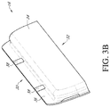
- FIG. 3B illustrates another perspective view of the window deflector of FIG. 3A .
- FIG. 3C illustrates another perspective view of the window deflector of FIG. 3A .
- FIG. 3D illustrates another perspective view of the window deflector of FIG. 3A .
- FIG. 3E illustrates a top view of the window deflector of FIG. 3A .
- FIG. 3F illustrates a bottom view of the window deflector of FIG. 3A .
- FIG. 3G illustrates a side view of the window deflector of FIG. 3A .
- FIG. 3H illustrates another side view of the window deflector of FIG. 3A .
- FIG. 3I illustrates another side view of the window deflector of FIG. 3A .
- FIG. 3J illustrates another side view of the window deflector of FIG. 3A .
- FIG. 4A illustrates a perspective view of a mounting clip of the window deflector assembly of FIG. 2A .
- FIG. 4B illustrates another perspective view of a mounting clip of FIG. 4A .
- FIG. 4C illustrates another perspective view of the mounting clip of FIG. 4A .
- FIG. 4D illustrates another perspective view of the mounting clip of FIG. 4A .
- FIG. 4E illustrates a top view of the mounting clip of FIG. 4A .
- FIG. 4F illustrates a bottom view of the mounting clip of FIG. 4A .
- FIG. 4G illustrates a side view of the mounting clip of FIG. 4A .
- FIG. 4H illustrates another side view of the mounting clip of FIG. 4A .
- FIG. 5A illustrates a window deflector assembly including a window deflector and mounting clips.
- FIG. 5B illustrates an enlarged perspective view of the window deflector assembly of FIG. 5A , including a window deflector and a mounting clip detached from the window deflector.
- FIG. 5C illustrates another enlarged perspective view of the window deflector assembly of FIG. 5A , with a mounting clip secured to a portion of the window deflector.
- a window deflector assembly which can be installed within a window channel of a window frame of a vehicle.
- the window deflector assembly can include a window deflector and a mounting clip.
- the mounting clip can include structure that allows the clip to engage both sides of a window channel and also secure a portion of the window deflector. Such engagement of both sides of a window channel affords the window deflector assembly the ability to withstand greater loads caused by, for example, wind or other forces and/or relative movement of the assembly within the window frame.
- the mounting clip can include structure, which can sandwich and/or grip a portion of the window deflector, thus allowing the mounting clip (or mounting clips) to be installed on the window deflector prior to securement of the mounting clip to the window channel of the vehicle.
- This provides an alternative installation method for the window deflector assembly that can be more convenient in some situations.
- the portion of the mounting clip configured to engage both sides of the window channel can have a curved (for example, arched) structure which can allow for convenient installation and can provide greater load distribution of vertical load arising from the window deflector to sides of the window channel.
- a portion of the window deflector secured by the mounting clip can define a recess sized to receive a portion of the mounting clip that grips the window deflector. This can provide a flush interface between the window deflector and the mounting clip at the connection region (also referred to herein as a “securement region”), which can allow a window (e.g., glass window) to pass adjacent to the interface without being contacted.
- the mounting clips discussed herein can secure window deflectors inside window frames of a vehicle without requiring the use of adhesives, such as tapes.
- FIG. 1A illustrates a side view of a vehicle 10 with window deflectors 16 installed proximate two windows 14 of the vehicle. More precisely, when installed, a portion of the window deflector 16 can be installed within a window channel 18 of a window frame 12 of a vehicle 10 (see, e.g., FIG. 2A-2B ).
- FIG. 1B shows an enlarged perspective view of the window deflectors 16 when installed.
- FIG. 2A-2B illustrate a cross-section of a window deflector 16 installed within a window channel 18 of a window frame 12 with a mounting clip 20 , where window 14 is in a closed position.
- window channel 18 is located within window frame 12 and includes two sides, one closer to an interior of the vehicle than the other.
- Window channel 18 can include one or more protrusions, such as one or more flared portions 15 .
- the one or more flared portions 15 can be vertically spaced along a height of one or both of the sides of the window channel 18 .
- the one or more flared portions 15 can be angled with respect to the sides of the window channel 18 .
- the one or more flared portions 15 can provide a contacting seal against sides of the window 14 when the window 14 is in a closed position (e.g., located at least partially within the window channel 18 ), while allowing the window 14 to close and open with relative ease.
- the window channel 18 can include two flared seal portions on each side of the window channel 18 , wherein the two flared seal portions 15 are spaced vertically with respect to one another.
- the window channel 18 can be rubber or another material, and/or can comprise a combination of materials.
- the flared portions 15 can be continuous and can extend along a portion of a length the window channel 18 .
- the flared portions 15 can be non-continuous (e.g., can be laterally spaced from one another along a portion of the length of the window channel 18 ).
- the window channel 18 provides structure that can be engaged by the mounting clips 20 disclosed herein.
- the window deflector 16 when the window deflector 16 is installed, a portion of the window deflector 16 can extend upward into (and/or be positioned within) the window frame 12 and another portion of the window deflector 16 can extend below (and/or be positioned outside) the window frame 12 and/or outward away from the window 14 of the vehicle 10 .
- Such configuration of the window deflector 16 can reduce interior wind noise.
- the mounting clip 20 can extend across a gap between the sides of the window channel 18 and window frame 12 and can engage both sides of the window channel 18 . Additionally or alternatively, the mounting clip 20 can engage the flared portion 15 on one or both sides of the window channel 18 . The structure and characteristics of the mounting clip 20 are discussed further below.
- the portion of the window deflector 16 extending upward into the window frame 12 can be secured by a portion of the mounting clip 20 .
- a portion of the window deflector 16 can be gripped by two stems of the mounting clip 20 on both sides of the window deflector 16 .
- the two stems of the mounting clip 20 can be inset or spaced inwardly from ends of the mounting clip 20 to accommodate the structure and/or configuration of the window channel 18 and/or window frame 12 (for example, the flared portions 15 of window channel 18 ).
- the two stems of the mounting clip 20 can be positioned closer to one end of the mounting clip 20 than the other, which can provide a gap to accommodate movement of the window 14 within the window channel 18 and/or window frame 12 when the mounting clip 20 and/or the window deflector 16 is installed within the window channel 18 .
- Such structure and configuration of the two stems of the mounting clip 20 advantageously avoids interfering with opening and closing of the window 14 within the window frame 12 , and problems associated with such interference.
- installation and/or securement of typical window deflectors and/or attachment devices utilize tapes to secure the attachment devices to the window channel 18 and/or window frame 12 .
- double-sided adhesive tapes are typically secured to a portion of the window channel 18 and/or window frame 12 and a surface of the attachment device, and portions of the window deflector are often wedged in between a portion of the attachment device and the window channel 18 and/or window frame 12 .
- portions of these attachment devices may sometimes stick out and bump against or otherwise interfere with a portion of the window 14 when the window 14 is being closed.
- Many windows and vehicle window systems include so called “anti-pinch” features that prevent closing of the window 14 if an obstacle or interference is sensed when the window 14 is being closed.
- anti-pinch features that prevent closing of the window 14 if an obstacle or interference is sensed when the window 14 is being closed.
- the structure and configuration of the mounting clip 20 can avoid such problem by providing an appropriate gap and/or spacing which allows movement of the window 14 within the window frame 12 , while also allowing the window deflector 14 to be secured between the two stems proximate to the window 14 when in the closed position. Additionally, because the mounting clip 20 can secure the window deflector 16 without relying on “wedging” the window deflector 16 against the window channel 18 , portions of mounting clip 20 that secure the window deflector 16 are not likely to be pushed outward so as to bump against or otherwise interfere with the window 14 when the window 14 is being closed (thus avoiding activation of “anti-pinch” features common in many automatic vehicle window systems).
- FIG. 2C illustrates a cross-section of the window frame 12 including the window channel 18 and a mounting clip 20 , without also showing the window deflector 16 and the window 14 .
- FIGS. 3A-3J illustrate various views of the window deflector 16 .
- Window deflector 16 can include a first section 36 configured to extend upward into (and/or be positioned within) the window frame 12 when installed and a second section 34 configured to extend below (and/or be positioned outside) the window frame 12 and/or outward from the window frame 12 when installed.
- the first section 36 and the second section 34 can be integral.
- the first section 36 and the second section 34 can be non-integral.
- the first section 36 can be inserted into the window frame 12 and/or window channel 18 at a top end 30 and/or along sides of the window deflector 16 between the top end 30 and a bottom end 32 .
- the second section 34 can protrude outward from the first section 36 .
- the first section 36 defines a rim extending along one or more sides of the window deflector 16 and/or around the second section 34 .
- the window deflector 16 can be secured to the one or more mounting clips 20 at one or more securement regions.
- the window deflector 16 can be secured to one or more mounting clips 20 at one or more securement regions along the first section 36 , such as one, two, three, four, five, six, seven, eight, nine, or ten or more securement regions along the first section 36 .
- the spacing between the one or more securement regions can be equal or unequal, depending on the configuration of the assembly of the window deflector 16 and the one or more mounting clips 20 .
- Each of the one or more securement regions can define a recess 38 .
- Recess 38 can be sized to receive an inner stem 24 of the mounting clip 20 (see, e.g., FIG. 4B ). Attention is directed to FIGS. 3C, 4B, and 2B . As discussed herein, when the mounting clip 20 is installed within the window channel 18 and a portion of the window deflector 16 (for example, the first section 36 ) is secured between the inner stem 24 and the outer stem 26 of the mounting clip 20 , the inner stem 24 can be positioned between the window deflector 16 and the window 14 .
- the window 14 when the window 14 is in a closed or partially closed position, there may be little or nor gap between the window 14 and the inner stem 24 which may result from the dimensional properties of any of these interacting components or may be a result of natural expansion of the components or materials thereof (e.g., thermal expansion).
- the minimal or non-existent gap between the window 14 and the inner stem 24 may result in contact between the window 14 and the inner stem 24 .
- the one or more securement regions of the window deflector 16 secured by the one or more mounting clips 20 can be recessed to receive the inner stem 24 within recess 38 so that the inner stem 24 does not protrude outward passed a face of the window deflector 16 , and/or protrude outward passed a face of the window deflector 16 beyond a certain distance.
- the window 14 can contact a face of the window deflector 16 (for example, a face of the first section 36 ) without also contacting the inner stem 24 .
- the recess(es) 38 can reduce forces and/or contact between the window 14 and the inner stem 24 .
- Recess(es) 38 can have a thickness (also referred to herein as “depth”) that is greater than, less than, or substantially equal to a thickness of the inner stem 24 .
- the thickness of the recess(es) 38 can be greater than the thickness of the inner stem 24 by no more than 30%, 20%, 10%, 8%, 5%, 2%, or 1%, or any value therebetween, or any range bounded by any combination of these values, although values outside these ranges can be used in some cases.
- the thickness of the recess(es) 38 can be a percentage of the thickness of the inner stem 24 , such as 70%, 75%, 80%, 85%, 90%, 95%, 100%, 105%, 110%, 115%, 120%, 125%, 130%, or any value therebetween, or any range bounded by these values.
- a surface of the window deflector 16 proximate to the recess(es) 38 and a face of the inner stem 24 can be flush (e.g., coplanar), which can prevent bumps and/or exposed edges in the interface between the window 14 and inner stem 24 and/or window deflector 16 when the window 14 is in the closed position or is moving to or from such position.
- a recess 38 with a thickness greater than a thickness of the inner stem 24 by 10% or more than 10% (such as 20% or 30%) depending on the materials used for the window deflector 16 and/or inner stem 24 .
- the thickness of the window deflector 16 may be selected to be, for example, 5% greater, 10% greater, 15% greater, 20% greater, 25% greater, 30% greater, or 40% greater than the thickness of the inner stem 24 .
- FIGS. 4A-4H illustrate various views of the mounting clip 20 .
- the mounting clip 20 can include a top portion 22 configured to secure to and/or within the window channel 18 .
- the top portion 22 can secure to one or both sides of the window channel 18 .
- the top portion 22 can include a first end 29 configured to engage a first side of the window channel 18 (for example, a side of the window channel 18 that is closer to an interior of a vehicle 10 ) and a second end 28 configured to engage a second side of the window channel 18 (for example, a side of the window channel 18 that is closer to an exterior of the vehicle 10 and opposite the side that is closer to the interior of the vehicle 10 ).
- the first and second ends 29 , 28 of the top portion 22 can engage the first and second sides of the window channel 18 by pressing and/or butting against the sides and/or sticking within a portion of the sides, for example (see, e.g., FIG. 2B ). Additionally or alternatively, the first and second ends 29 , 28 of the top portion 22 can engage the first and second sides of the window channel 18 by extending beyond an end or tip of the flared portions 15 of the window channel 18 . Additionally or alternatively, the first and second ends of the top portion 22 can rest atop and/or within the flared portion(s) 15 of the window channel 18 .
- the top portion 22 of the mounting clip 20 can be curved downwardly toward the first end 29 and/or curved downwardly toward the second end 28 .
- the flared portion(s) 15 are angled upward towards a top of the window frame 12 (see FIG. 2B )
- the downwardly curved first and second ends 29 , 28 of the top portion 22 can engage the angled flared portion(s) 15 so that a contacting surface of the first and second ends of the top portion 22 lays adjacent to a contacting surface of the angled flared portion(s) 15 .
- Such engagement may occur when, for example, vertical load is applied to the top portion 22 of the mounting clip 20 in a downward direction from the weight of the window deflector 16 , thus pulling the top portion 22 downward so that the first and second ends 29 , 28 fall into a space defined between the angled flared portion(s) 15 and the sides of the window channel 18 .
- the top portion 22 of the mounting clip 20 can have a curved structure which can allow for convenient installation and can provide greater and more efficient load distribution of vertical load (e.g., arising from the weight of the window deflector 16 when secured to the mounting clip 20 ) to sides of the window channel 18 .
- the top portion 22 of the mounting clip 20 can be curved downwardly toward the first end 29 and curved downwardly toward the second end 28 . This structure and curvature can allow the mounting clip 20 to be inserted upward into the window channel 18 and passed the flared portion(s) 15 of the window channel 18 with relative ease, while also allowing first and second ends 29 , 28 of the top portion 20 to engage one or both sides of the window channel 18 when in an installed position.
- the curvature of the top portion 20 can also help provide efficient load distribution. For example, where the window deflector 16 is secured by inner stem 24 and outer stem 26 of the mounting clip 20 , downward vertical load is applied to the top portion 22 of the mounting clip 20 .
- the curvature of the top portion 22 which can be arch-shaped, can efficiently distribute such vertical load to sides of the window channel 18 . This curvature and efficient load distribution allows the mounting clip 20 to carry and transfer greater vertical loads resulting from the window deflector 16 and reduces the likelihood that the window deflector 16 will dislodge from the window channel 18 , especially at high vehicle speeds and/or when wind or other forces or conditions are present.
- the mounting clip 20 can include one or more engagement portions configured to engage one or both sides of window channel 18 , such as at least one, at least two, at least three, at least four, at least five or at least six engagement portions.
- the mounting clip 20 can include one or more engagement portions 40 , 42 on the top portion 22 configured to engage one or both sides of the window channel 18 .
- the top portion 22 can include one or more engagement portions 42 at or proximate to the first end 29 of the top portion 22 and/or can include one or more engagement portions 40 at or proximate to the second end 28 of the top portion 22 .
- the one or more engagement portions 40 , 42 can be laterally spaced from one another along the first and/or second ends of the top portion 22 .
- the one or more engagement portions 40 , 42 can be equally or un-equally spaced from one another along the first and/or second ends 29 , 28 of the top portion 22 .
- the one or more engagement portions 40 , 42 can be tapered from sides of the engagement portions 40 , 42 to form a pointed tip when viewed from above (see FIG. 4E ) which can assist the top portion 22 to better engage one or both sides of the window channel 18 .
- the pointed tip can help the one or more engagement portions 40 , 42 to press and/or dig into one or both sides of the window channel 18 .
- first and second ends 29 , 28 of the top portion 22 can be curved downwardly and can engage angled flared portion(s) 15 of the window channel 18 .
- first and second ends of the top portion 22 can be curved downwardly and can engage angled flared portion(s) 15 of the window channel 18 such that a contacting surface of the first and second ends 29 , 28 of the top portion 22 lays adjacent to a contacting surface of the angled flared portion(s) 15 .
- first and second ends 29 , 28 of the top portion 22 include one or more engagement portions 40 , 42
- the one or more engagement portions 40 , 42 can have contacting surfaces that lay adjacent to contacting surfaces of the angled flared portion(s) 15 . This can advantageously provide robust securement in addition or as an alternative to having the first and second ends 29 , 28 of the top portion 22 press against one or both of the sides of the window channel 18 .
- the mounting clip 20 can include an outer stem 26 and an inner stem 24 .
- the outer stem 26 can be at or proximate to the first end 29 of the top portion 22 .
- the inner stem 24 can be spaced from the outer stem 26 so as to allow a portion of the window deflector 16 (such as a portion of the first section 36 of window deflector 16 ) to be received therewithin.
- the spacing between the inner stem 24 and the outer stem 26 can be sized to allow the inner and outer stems 24 , 26 grip the portion of the window deflector 16 so as to secure (e.g., hold) it in position within the mounting clip 20 .
- the inner and outer stems 24 , 26 can grip the portion of the window deflector 16 on both sides, thus providing robust securement and significantly reducing the likelihood that the window deflector 16 will dislodge from the window channel 18 , especially at high vehicle speeds and/or when wind or other forces or conditions are present.
- the inner stem 24 can be retained within a recess 38 of the window deflector 16 , which can provide the advantages discussed above.
- the mounting clip 20 can include one or more engagement portions 43 that can extend inwardly (e.g., toward inner stem 24 ) from a face of the outer stem 26 .
- These engagement portions 43 can extend toward a portion of the window deflector 16 that is retained between the inner and outer stems 24 , 26 and can press and/or butt against the portion of the window deflector 16 when installed.
- the engagement portions 43 can be the same in some, many or all respects as engagement portions 40 , 42 .
- the engagement portions 43 can be laterally spaced from one another along the face of the outer stem 26 .
- the engagement portions 43 can be equally or un-equally spaced from one another along the face of the outer stem 26 .
- the engagement portions 43 can have a pointed tip (see, e.g., FIG. 4B ) which can assist the outer stem 26 to better engage a face of the window deflector 16 .
- the one or more engagement portions 43 can be angled upwards, for example, which can allow a portion of the window deflector 16 to be inserted between the inner and outer stems 24 , 26 with relative ease while advantageously also making removal of the portion of the window deflector 16 more difficult. This configuration of the engagement portions 43 thus can reduce the likelihood of unintended dislodgement of the window deflector 16 from the mounting clip 20 .
- the inner stem 24 can also have one or more engagement portions extending inwardly from a face of the inner stem 24 (e.g., towards outer stem 26 ), which can be the same in some or all respects as engagement portions 43 .
- the outer stem 26 can have a cantilevered end 27 that can be flared.
- the cantilevered end 27 of the outer stem 26 can be flared outward and configured to engage a portion of a side of the window channel 18 when the mounting clip 20 is installed within the window frame 12 .
- the flared cantilevered end 27 can engage a side of the window channel 18 by pressing and/or butting against the side and/or sticking within a portion of the side, for example.
- the flared cantilevered end 27 can engage a side of the window channel 18 by extending beyond an end or tip of the flared portion(s) 15 of the window channel 18 .
- the flared cantilevered end 27 can rest atop the flared portion(s) 15 of the window channel 18 , and/or can rest within a space defined between the flared portion(s) 15 and the sides of window channel 18 . Similar to as that discussed above with respect to the engagement portions 40 , 42 of the mounting clip 20 , the flared cantilevered end 27 can engage the angled flared portion(s) 15 so that a contacting surface of the flared cantilevered end 27 lays adjacent to a contacting surface of the angled flared portion(s) 15 .
- Such engagement may occur when, for example, vertical load is applied to the top portion 22 of the mounting clip 20 in a downward direction from the weight of the window deflector 16 , thus pulling the flared cantilevered end 27 downward so that it falls into the space defined between the angled flared portion(s) 15 and the sides of the window channel 18 .
- the flared cantilevered end 27 can advantageously provide additional securement of the mounting clip 20 to the window channel 18 at a location below the first and/or second ends 29 , 28 of the top portion 22 of the mounting clip 20 , which can aid in load transfer and balance of the window deflector assembly.
- the top portion 22 of mounting clip 20 can be uniform in cross-section from the first end 29 to the second end 28 .
- the top portion 22 can be non-uniform in cross-section from the first end 29 to the second end 28 .
- the top portion 22 can have a body 22 a and a tail 22 b that is narrower than body 22 a .
- the tail 22 b can have a length and/or width that is smaller than a length and/or width of the body 22 a .
- FIG. 4E the top portion 22 can have a body 22 a and a tail 22 b that is narrower than body 22 a .
- the tail 22 b can have a length and/or width that is smaller than a length and/or width of the body 22 a .
- the shape and structure of the body 22 a and tail 22 b of the top portion 22 as well as the shape and structure of the inner and outer stems 24 , 26 allows the various elements to be constructed from a single piece of material during manufacturing.
- a single flat piece of material can be bent to form the body 22 a of the top portion 22 and the tail 22 b and outer stem 26 can be cut from the part of the piece of material defining the inner stem 24 . This in turn can leave an opening in the inner stem 24 , as shown.
- FIG. 5A illustrates a perspective view of the window deflector 16 and the one or more mounting clips 20 , where some mounting clips 20 are secured to the window deflector 16 and some mounting clips 20 are not secured to (e.g., are detached) the window deflector 16 .
- FIG. 5B illustrates an enlarged perspective view of a mounting clip 20 proximate to the window deflector 16 and recess 38 prior to installation (e.g. securement).
- FIG. 5C illustrates an enlarged perspective view of a mounting clip 20 secured within a recess 38 of the window deflector 16 . The benefits and properties of the retainment of the inner stem 24 within the recess 38 are discussed above.
- the recess 38 can be sized to receive the inner stem 24 within the recess 38 and/or can have a thickness that is substantially equal to a thickness of the inner stem 24 so that a face (e.g., window-facing face) of the inner stem 24 is flush with a surface of the window deflector 16 (e.g., a face of the first section 36 of window deflector 16 ) when the mounting clip 20 is secured to the window deflector 16 .
- the window deflector 16 and one or more mounting clips 20 discussed herein can be secured to one another and/or to a window channel 18 and/or window frame 12 of a vehicle 10 in a variety of different ways and in a variety of different orders.
- the window deflector 16 and one or more mounting clips 20 can be secured to a window channel 18 and/or window frame 12 of a vehicle 10 by first securing the mounting clip(s) 20 to the window channel 18 , and thereafter securing the window deflector 16 to the mounting clip(s) 20 .
- Installation of the window deflector 16 within a window channel 18 and/or window frame 12 may begin be inserting one or more mounting clips 20 into the window channel 18 and/or window frame 12 and securing the one or mounting clips 20 to the window channel 18 .
- the mounting clips 20 can be secured to the window channel 18 by securing first and/or second ends 29 , 28 of the top portion 22 of the mounting clips 20 to one or both sides of the window channel 18 , as discussed above.
- one or more portions of the window deflector 16 can be inserted into a second portion of the mounting clip 20 , such as between the inner and outer stems 24 , 26 of the mounting clip 20 , as described above.
- the window deflector 16 and one or more mounting clips 20 can be secured to a window channel 18 and/or window frame 12 of a vehicle by first securing the mounting clip(s) 20 to the window deflector 16 , and thereafter securing the mounting clip(s) 20 to the window channel 18 of the window frame 12 of the vehicle 10 .
- the mounting clip(s) 20 can be secured to a first section 36 of the window deflector 16 , such as at recess(es) 38 . Once the mounting clip(s) 20 are secured to the window deflector 16 in desired locations and/or positions, the assembly can be inserted into the window frame and the mounting clip(s) 20 can be secured to the window channel 18 .
- This approach may be advantageous because it can allow the placement of the one or more mounting clips 20 to be more precise.
- a user can place the mounting clip(s) 20 in locations along the window deflector 16 so as to distribute the loads (from the attachment) at pre-defined spacings or intervals along the window frame 12 and/or window channel 18 . If the mounting clips 20 are placed in the window channel 18 before the window deflector 16 is inserted into the mounting clips 20 , the mounting clips 20 may move or be inadvertently pushed by the user and/or window deflector 16 during installation.
- window deflector 16 includes recesses 38
- alignment and/or placement of the mounting clips 20 within the recesses 38 can be accomplished much more easily when the clips 20 are attached to the window deflector 16 prior to installation of the assembly to the window channel 18 .
- the top portion 22 of the mounting clip(s) 20 can be curved downwardly toward the first end 29 and curved downwardly toward the second end 28 . As also discussed, this curvature can advantageously make installation of the mounting clips 20 within the channel 18 more efficient as it provides less resistant when the top portion 22 is pushed upward in the window channel 18 , especially where the window channel 18 includes flared portion(s) 15 .
- the above recited ranges can be specific ranges, and not within a particular % of the value. For example, within less than or equal to 10 wt./vol. % of, within less than or equal to 5 wt./vol. % of, within less than or equal to 1 wt./vol. % of, within less than or equal to 0.1 wt./vol. % of, and within less than or equal to 0.01 wt./vol. % of the stated amount.
Landscapes
- Engineering & Computer Science (AREA)
- Mechanical Engineering (AREA)
- Seal Device For Vehicle (AREA)
- Connection Of Plates (AREA)
Abstract
Description
Claims (20)
Priority Applications (1)
| Application Number | Priority Date | Filing Date | Title |
|---|---|---|---|
| US16/600,933 US11220161B2 (en) | 2018-10-26 | 2019-10-14 | Window deflector assembly with mounting clips |
Applications Claiming Priority (2)
| Application Number | Priority Date | Filing Date | Title |
|---|---|---|---|
| US201862751152P | 2018-10-26 | 2018-10-26 | |
| US16/600,933 US11220161B2 (en) | 2018-10-26 | 2019-10-14 | Window deflector assembly with mounting clips |
Publications (2)
| Publication Number | Publication Date |
|---|---|
| US20200130479A1 US20200130479A1 (en) | 2020-04-30 |
| US11220161B2 true US11220161B2 (en) | 2022-01-11 |
Family
ID=70328607
Family Applications (1)
| Application Number | Title | Priority Date | Filing Date |
|---|---|---|---|
| US16/600,933 Active 2040-05-19 US11220161B2 (en) | 2018-10-26 | 2019-10-14 | Window deflector assembly with mounting clips |
Country Status (2)
| Country | Link |
|---|---|
| US (1) | US11220161B2 (en) |
| CA (1) | CA3059857A1 (en) |
Cited By (2)
| Publication number | Priority date | Publication date | Assignee | Title |
|---|---|---|---|---|
| US20220048373A1 (en) * | 2020-08-12 | 2022-02-17 | Jiing-Duen Enterprise Co., Ltd. | Car Rain Guard |
| USD1023894S1 (en) * | 2022-06-16 | 2024-04-23 | Shenzhen Zhengtu Auto Accessories Co., Ltd. | Vehicle rain gutter |
Families Citing this family (6)
| Publication number | Priority date | Publication date | Assignee | Title |
|---|---|---|---|---|
| US11220161B2 (en) | 2018-10-26 | 2022-01-11 | Lund, Inc. | Window deflector assembly with mounting clips |
| USD898640S1 (en) | 2018-10-26 | 2020-10-13 | Bushwacker, Inc. | Vehicle fender flare |
| USD906200S1 (en) | 2018-10-26 | 2020-12-29 | Bushwacker, Inc. | Fender flare |
| US11225213B2 (en) | 2018-10-26 | 2022-01-18 | Lund, Inc. | Vehicle body shield |
| CA187177S (en) | 2018-10-26 | 2020-10-22 | Bushwacker Inc | Fender flare |
| USD906202S1 (en) | 2018-10-26 | 2020-12-29 | Bushwacker, Inc. | Fender flare |
Citations (359)
| Publication number | Priority date | Publication date | Assignee | Title |
|---|---|---|---|---|
| CA64701A (en) | 1899-05-01 | 1899-11-02 | John P. Harrington | Apparatus for making crank shafts |
| CA76555A (en) | 1901-07-08 | 1902-07-01 | Henry Edward Poehlman | Explosive |
| US1453340A (en) | 1919-01-03 | 1923-05-01 | Packard Motor Car Co | Attachment for motor-vehicle radiators |
| US1588654A (en) | 1924-10-27 | 1926-06-15 | Kenneth H Brownlee | Ventilator for closed vehicles |
| US1787035A (en) | 1930-06-30 | 1930-12-30 | Davis Tool & Eng Co | Shield for automobile radiators |
| US1811527A (en) | 1930-09-08 | 1931-06-23 | Fred M Young | Radiator |
| US1825192A (en) | 1928-11-27 | 1931-09-29 | Mace John Jacob | Window ventilator for autos |
| US2054538A (en) | 1934-10-06 | 1936-09-15 | Int Harvester Co | Radiator guard |
| US2059305A (en) | 1933-10-23 | 1936-11-03 | Packard Motor Car Co | Motor vehicle |
| US2073159A (en) | 1935-01-15 | 1937-03-09 | Evans Prod Co | Vehicle ventilating and signal unit |
| US2106418A (en) | 1935-04-03 | 1938-01-25 | Wagner Hans | Car ventilator |
| US2184798A (en) | 1938-06-23 | 1939-12-26 | Glen A Gracey | Device for deflecting air streams |
| US2236846A (en) | 1939-05-10 | 1941-04-01 | Roy S Davisson | Snow and insect shield |
| US2281840A (en) | 1940-09-28 | 1942-05-05 | Clark S Hamilton | Air deflector for motor vehicles |
| US2475901A (en) | 1948-02-09 | 1949-07-12 | William T Kipp | Sun visor |
| US2534763A (en) | 1948-05-17 | 1950-12-19 | Clarence B Flavin | Exterior-type sun visor |
| US2566934A (en) | 1949-07-06 | 1951-09-04 | Richard E Dieterich | Combined vehicle windshield shade and traffic signal finder |
| US2567501A (en) | 1948-05-27 | 1951-09-11 | George J Zeis | Visor for automobiles |
| US2599809A (en) | 1949-02-25 | 1952-06-10 | William F Branch | Sun visor for motor vehicles |
| FR1067336A (en) | 1952-12-01 | 1954-06-15 | Defleur Soc Ets | New method of fixing motor vehicle windshield protection screens |
| FR1096819A (en) | 1952-11-17 | 1955-06-27 | R Breuil & J Buchet Ets | Improvements to screens intended to be placed on the hood of motor vehicles |
| GB734743A (en) | 1953-10-15 | 1955-08-03 | William Edward O Shei | Improvements in or relating to deflectors for automobile windscreens |
| US2749830A (en) | 1954-10-26 | 1956-06-12 | Landon C George | Ventilator attachment for automobiles |
| FR1121035A (en) | 1955-02-01 | 1956-07-19 | Articulated support for windshield guard | |
| US2757954A (en) | 1952-04-25 | 1956-08-07 | Curtiss Wright Corp | Insect deflector for automobiles |
| US2777732A (en) | 1954-12-01 | 1957-01-15 | Thomas S Walsh | Clear vision rain visors |
| US2792254A (en) | 1956-04-06 | 1957-05-14 | Eugene A Hagglund | Bug and gravel shield for vehicles |
| US2793705A (en) | 1955-10-11 | 1957-05-28 | Robert K Garrity | Insect and debris deflector for motor vehicle hood front surface |
| US2857973A (en) | 1956-07-03 | 1958-10-28 | Robert K Garrity | Insect and debris deflector |
| US2859680A (en) | 1954-01-25 | 1958-11-11 | O'shei William Edward | Ventilating device for the bodies of motor cars and other passenger carrying vehicles |
| GB829154A (en) | 1957-08-08 | 1960-02-24 | Denis James Battersby | Exterior windscreen visor for vehicles |
| US2949842A (en) | 1956-11-21 | 1960-08-23 | Arthur B Crandall | Automobile window ventilator |
| US3015517A (en) | 1959-05-25 | 1962-01-02 | Argyle K Thornburgh | Air current deflector shield |
| US3022848A (en) | 1959-09-28 | 1962-02-27 | Heiser Bennett John | Protective hood shield for vehicles |
| US3214216A (en) | 1962-12-31 | 1965-10-26 | Jr George E Brown | Disposable windshield canopy |
| US3434408A (en) | 1966-07-14 | 1969-03-25 | Joe F Rivers | Vehicle window air vent |
| US3487420A (en) | 1966-06-18 | 1969-12-30 | Happich Gmbh Gebr | Molding strip for automobile bodies |
| US3678635A (en) | 1971-03-26 | 1972-07-25 | Ford Motor Co | Assembly having integral sealing means |
| US3695674A (en) | 1970-10-09 | 1972-10-03 | William W Baker | Combination vehicle stabilizer and bug deflector |
| US3728537A (en) | 1968-08-28 | 1973-04-17 | Daimler Benz Ag | Arrangement of front and/or rear lights of motor vehicles |
| US3736404A (en) | 1969-12-18 | 1973-05-29 | P Eisler | Combined demisting and defrosting heating panel for windows and other transparent areas |
| US3785699A (en) | 1972-06-26 | 1974-01-15 | C Molaskey | Wind deflector for automobiles |
| US3815700A (en) | 1972-11-13 | 1974-06-11 | T Mittendorf | Vehicle insect protection apparatus |
| US3866524A (en) | 1973-05-11 | 1975-02-18 | Jr Hampton E Forbes | Vehicle window ventilator |
| US3866527A (en) | 1973-04-25 | 1975-02-18 | Thomas C Katris | Rotisserie |
| US3987863A (en) | 1975-12-29 | 1976-10-26 | Mittendorf Theodor H | Vehicle insect protection apparatus |
| US4018472A (en) | 1976-02-04 | 1977-04-19 | General Motors Corporation | Tractor-trailer aerodynamic drag reducer |
| US4039221A (en) | 1976-01-27 | 1977-08-02 | Clarence Eady | Safety wind deflector |
| US4040656A (en) | 1975-06-11 | 1977-08-09 | Clenet Alain Jean Marie | Bug deflector |
| US4043587A (en) | 1976-04-09 | 1977-08-23 | Giallourakis Michael A | Bug deflecting devices |
| US4052099A (en) | 1976-05-07 | 1977-10-04 | Dixson, Inc. | Oncoming air spoilers for vehicles, mounted near the hood to deflect air carried bugs, rain, road spray, snow, and lightweight debris up and away from the windshield |
| US4063773A (en) | 1976-07-30 | 1977-12-20 | Modesette J Harley | Air deflector |
| US4089256A (en) | 1975-05-12 | 1978-05-16 | Furcini James F | Wind deflector for an automotive vehicle |
| US4099760A (en) | 1977-05-05 | 1978-07-11 | Mascotte Lawrence L | Grill and brush guard and utility rack for a vehicle |
| US4149749A (en) | 1977-02-11 | 1979-04-17 | Exacon International-Establishment | Roof lining element for vehicle cabins |
| US4153129A (en) | 1977-11-11 | 1979-05-08 | Deflecta-Shield Corp. | Air current deflector shield for vehicles |
| US4159845A (en) | 1978-03-22 | 1979-07-03 | Bratsberg Glenn N | Airstream deflector for motor vehicles |
| USD252680S (en) | 1977-05-02 | 1979-08-21 | Kingsley Michael C | Exterior visor for vehicles |
| US4169608A (en) | 1978-01-16 | 1979-10-02 | L.T.D. Enterprises, Inc. | Fender extensions |
| US4174021A (en) | 1978-05-16 | 1979-11-13 | Alnor Material Handling Limited | Ladder truck |
| US4174850A (en) | 1978-05-30 | 1979-11-20 | Hart Richard K | Fender flare clip apparatus |
| US4178034A (en) | 1978-01-30 | 1979-12-11 | Mittendorf Theodor H | Vehicle insect protection apparatus |
| US4191097A (en) | 1978-09-11 | 1980-03-04 | Groen Don L | Air deflector for motor vehicles |
| US4219870A (en) | 1978-07-07 | 1980-08-26 | Gte Sylvania Incorporated | Front loading projection unit |
| USD256793S (en) | 1978-01-16 | 1980-09-09 | Logan Gerald A | Fender extension unit |
| GB2046183A (en) | 1979-03-01 | 1980-11-12 | Nissan Motor | Wing Construction of Automotive Vehicles |
| US4262954A (en) | 1979-03-15 | 1981-04-21 | Thompson Marlon H | Frontal assembly for vehicles |
| USD259873S (en) | 1978-07-24 | 1981-07-14 | Milner William J | Grill guard for vans |
| USD261500S (en) | 1978-12-04 | 1981-10-27 | Affiliated Hatch And Sunroof, Inc. | Vehicle visor |
| US4309056A (en) | 1979-11-26 | 1982-01-05 | Long Alvin L | Air deflector support structure |
| US4320919A (en) | 1978-12-21 | 1982-03-23 | Affiliated Hatch And Sunroof, Inc. | Aerodynamic visor |
| USD264833S (en) | 1980-03-20 | 1982-06-08 | Trombley Ulric W | Trim piece for an automobile hood |
| US4347781A (en) | 1979-07-10 | 1982-09-07 | Hassell Aarno A | Air deflector for motor vehicle windows |
| US4364591A (en) | 1981-04-24 | 1982-12-21 | Chrysler Corporation | Eyelet trim strip fastening arrangement |
| US4412698A (en) | 1981-08-18 | 1983-11-01 | Kingsley Michael C | Method and apparatus for attaching sun visor to an automobile |
| US4423668A (en) | 1979-11-08 | 1984-01-03 | Long Alvin L | Universal air deflector |
| USD272429S (en) | 1981-04-27 | 1984-01-31 | Trombley Ulric W | Trim piece for an automobile hood |
| USD273672S (en) | 1981-11-25 | 1984-05-01 | Lund Allan W | Windshield visor for trucks |
| US4447067A (en) | 1980-10-06 | 1984-05-08 | Toshio Yamashita | Automobile fender protector formed of synthetic resin |
| US4471991A (en) | 1982-12-20 | 1984-09-18 | Autotron Products, Inc. | Articulated deflector shield assembly and interchangeable frame mounting system therefor |
| US4476774A (en) | 1982-04-05 | 1984-10-16 | Liberto Samuel J | Portable universal wind deflector |
| US4493577A (en) | 1982-08-20 | 1985-01-15 | Rexnord Inc. | Double disc stud assembly for thin walled panels |
| US4527466A (en) | 1983-08-08 | 1985-07-09 | Kossor Albert A | Automobile ventilation exhaust and rain shield |
| US4547013A (en) | 1984-06-28 | 1985-10-15 | Tomahawk Industries, Inc. | Vehicle bug deflector |
| JPS6157471A (en) | 1984-08-29 | 1986-03-24 | Nissan Motor Co Ltd | Ornamental member setting structure in fender opening part |
| USD283120S (en) | 1983-09-29 | 1986-03-25 | Double D Specialties, Inc. | Trim piece for an automobile hood |
| USD283611S (en) | 1983-11-21 | 1986-04-29 | Michael C. Kingsley | Exterior visor for vehicles |
| US4592937A (en) | 1984-08-28 | 1986-06-03 | Toyoda Gosei Co., Ltd. | Arcuate side molding |
| USD284565S (en) | 1984-01-30 | 1986-07-08 | Double D Specialties, Inc. | Trim piece for an automobile hood |
| US4605238A (en) | 1983-04-28 | 1986-08-12 | Arenhold K | Device for fixing a mud flap to the fender fold of a motor vehicle |
| US4621824A (en) | 1984-06-06 | 1986-11-11 | Arenhold K | Elongated spacer for arrangement between a mud flap and motor vehicle fender fold |
| US4627657A (en) | 1984-05-17 | 1986-12-09 | Autotron Products, Inc. | Truck deflector shield |
| USD288309S (en) | 1983-09-02 | 1987-02-17 | Allan W. Lund | Windshield visor for trucks |
| USD288310S (en) | 1983-09-02 | 1987-02-17 | Allan W. Lund | Windshield visor for trucks |
| US4671552A (en) | 1986-02-14 | 1987-06-09 | Owens Products, Inc. | Grill guard for vehicle front end |
| US4685718A (en) * | 1986-06-09 | 1987-08-11 | Liberty Specialties, Inc. | Device for attaching rain shields to motor vehicle windows |
| USD291295S (en) | 1983-09-02 | 1987-08-11 | Lund Allan W | Windshield visor for trucks |
| US4700980A (en) | 1986-11-17 | 1987-10-20 | General Motors Corporation | Wind deflector for vehicle side window |
| US4707014A (en) | 1986-11-14 | 1987-11-17 | Riverside International, Inc. | Automotive roof spoiler having retractable, concealable lamps |
| US4709938A (en) | 1985-11-18 | 1987-12-01 | Powerflow, Inc. | Splash guard |
| US4726619A (en) | 1987-03-10 | 1988-02-23 | Oyvind Haugestad | Split universal sun visor for a vehicle windshield |
| USD294707S (en) | 1985-07-18 | 1988-03-15 | Dresser Industries, Inc. | Radiator guard for a construction vehicle |
| JPS63130479A (en) | 1986-11-19 | 1988-06-02 | Daihatsu Motor Co Ltd | Rust preventing method for rear wheel house part |
| US4750549A (en) | 1986-06-09 | 1988-06-14 | Autotron Products, Inc. | Radiator grille cover with adjustable center openings |
| US4756242A (en) | 1987-12-14 | 1988-07-12 | Keith William C | Vehicle window ventilator |
| US4758040A (en) | 1986-04-07 | 1988-07-19 | Michael C. Kingsley | Exterior visor for automotive vehicles |
| US4776627A (en) | 1988-03-07 | 1988-10-11 | Ernest Hutto | Wind deflector and bug screen clip |
| US4784430A (en) | 1988-02-01 | 1988-11-15 | Chrysler Motors Corporation | Clip and wheel flair molding assembly |
| USD299713S (en) | 1986-12-15 | 1989-02-07 | Dunham Leslie N | Vehicle sunvisor |
| US4819136A (en) | 1986-05-16 | 1989-04-04 | Edward Ramsey | Running board light assembly |
| USD300918S (en) | 1988-03-18 | 1989-05-02 | G. T. Styling, Inc. | Hood protector shield |
| USD301028S (en) | 1987-04-06 | 1989-05-09 | D. H. Buck Co., Inc. | Windshield visor |
| USD301450S (en) | 1986-10-03 | 1989-06-06 | Saturn Corporation | Vehicle exterior sun visor |
| US4842320A (en) | 1986-10-03 | 1989-06-27 | Saturn Corporation | Vehicle exterior sun visor |
| US4842319A (en) | 1987-10-13 | 1989-06-27 | Autotron Products, Inc. | Deflector shield and guard assembly for motor vehicles |
| US4842912A (en) | 1985-09-04 | 1989-06-27 | Physical Systems, Inc. | Adhesive attachment and mounting fixture |
| US4844529A (en) | 1988-01-19 | 1989-07-04 | Saben Stephen V O | Wind deflector |
| USD304437S (en) | 1988-11-04 | 1989-11-07 | E&G Classics, Inc. | Grille cap for a vehicle |
| USD304819S (en) | 1987-09-14 | 1989-11-28 | General Motors Corporation | Combined rear spoiler and light |
| US4904014A (en) | 1988-08-26 | 1990-02-27 | General Motors Corporation | Decorative trim molding assembly |
| DE3932142A1 (en) | 1988-09-27 | 1990-04-05 | Hans Striewski | Retractable entrance step for caravan - is held in retracted or in extended positions by pins which engage slots |
| US4923241A (en) | 1989-01-23 | 1990-05-08 | Miller Evelyn B | Weather window shield for automotive vehicles and the like |
| US4929013A (en) | 1989-06-27 | 1990-05-29 | Lund Industries, Inc. | Airflow deflector apparatus |
| DE3843803A1 (en) | 1988-12-24 | 1990-07-05 | Broeking & Co | Frontal protection for motor vehicles |
| US4966404A (en) | 1988-12-16 | 1990-10-30 | Lund Industries, Inc. | Windshield visor for trucks having cab roof lights |
| USD312238S (en) | 1988-08-26 | 1990-11-20 | Lund Industries, Incorporated | Visor for pickup trucks |
| USD319209S (en) | 1989-07-24 | 1991-08-20 | Miller Rodney A | Vehicle visor |
| US5042551A (en) | 1990-09-17 | 1991-08-27 | Alan Ein | Removable window cover system for recreational vehicles |
| US5048868A (en) | 1989-06-06 | 1991-09-17 | Cona Gmbh | Mud-flap attachment device |
| EP0447640A2 (en) | 1990-03-20 | 1991-09-25 | Webasto AG Fahrzeugtechnik | Frame-spoiler arrangement for the fixation on the fixed part of a vehicle roof |
| US5067760A (en) | 1991-03-06 | 1991-11-26 | Moore Daniel E | Platform/grill cover unit for use on a land vehicle |
| US5082321A (en) | 1991-01-22 | 1992-01-21 | Brewer Shelby L | Air streamlining deflector shield for a motor vehicle |
| US5112095A (en) | 1990-07-26 | 1992-05-12 | Lund Industries, Incorporated | Vehicle shield device |
| US5114205A (en) | 1991-07-12 | 1992-05-19 | Jee Elwood Y | Vehicular air deflector |
| USD326636S (en) | 1990-10-19 | 1992-06-02 | Barth David J | Wind deflector for the roof of a vehicle having a T-top |
| US5120082A (en) | 1990-03-26 | 1992-06-09 | Kinugawa Rubber Industrial Co., Ltd. | Mud guard with reinforcement film |
| US5130906A (en) | 1990-10-05 | 1992-07-14 | Lund Industries, Incorporated | Flush mounted visor light |
| US5150941A (en) | 1991-11-20 | 1992-09-29 | Arvan, Inc. | Side window air deflector incorporating a side view mirror |
| US5183303A (en) | 1991-09-26 | 1993-02-02 | The Standard Products Company | Decorative trim attaching method |
| US5215343A (en) | 1989-08-11 | 1993-06-01 | Jib Engineering Ltd. | Nudge bars |
| US5234247A (en) | 1991-09-09 | 1993-08-10 | Dfm Corporation | Quick release deflector shield |
| US5238268A (en) | 1991-09-27 | 1993-08-24 | Bushwacker Inc. | Multiple piece vehicle fender extension |
| US5251953A (en) * | 1992-01-13 | 1993-10-12 | National Cycle, Inc. | Vehicle window air deflector |
| US5280386A (en) | 1990-03-19 | 1994-01-18 | Paccar Inc. | Windsheild deflector sheild with lens and/or rearview mirrors |
| US5284376A (en) | 1990-10-19 | 1994-02-08 | Mercedes-Benz Ag | Motor vehicle windscreen having strip-shaped opaque dot pattern |
| US5308134A (en) | 1993-03-30 | 1994-05-03 | Dfm Corporation | Heavy truck bug and gravel shield |
| US5320461A (en) | 1992-11-02 | 1994-06-14 | Dfm-Corporation | Fastener for air current deflector shields |
| USD348242S (en) | 1992-12-31 | 1994-06-28 | Hsiang-Wei Tsao | Vehicle sunshield |
| US5340154A (en) | 1991-02-22 | 1994-08-23 | Warn Industries, Inc. | Fender flare for a vehicle |
| US5348363A (en) | 1993-03-12 | 1994-09-20 | Kenco/Williams | Vehicle windshield bug and debris deflector |
| US5353571A (en) | 1991-05-29 | 1994-10-11 | Pebra, Inc. | Mounting of body moulding and related assemblies |
| USD352491S (en) | 1993-06-30 | 1994-11-15 | Carlo Galasso | Hood protector |
| US5403059A (en) | 1993-02-23 | 1995-04-04 | G.T. Styling, Inc. | Vehicle hood shield and method of mounting thereof |
| US5456786A (en) | 1993-03-22 | 1995-10-10 | Plastic Trim, Inc. | Trim strip and method for making same |
| US5460425A (en) | 1994-09-09 | 1995-10-24 | Stephens; Timothy M. | Gutter and visor system for a window of a vehicle |
| US5475956A (en) | 1992-09-25 | 1995-12-19 | Donnelly Corporation | Panel assembly |
| US5522634A (en) | 1994-08-02 | 1996-06-04 | Dfm Corporation | Visor accessory with sun shield insert and running lights |
| USD375068S (en) | 1994-10-21 | 1996-10-29 | Lund Industries, Inc. | Side window cover for vehicle |
| US5595416A (en) | 1994-08-05 | 1997-01-21 | Horwill; Rodney E. | Retaining clips for vehicle hood protectors |
| US5613710A (en) | 1995-06-12 | 1997-03-25 | Waner; Alan R. | Dual rear wheel fender liner |
| US5636892A (en) | 1995-04-05 | 1997-06-10 | Gordon; Adrian D. | Multi-purpose deflector apparatus for a vehicle |
| USD379956S (en) | 1994-08-19 | 1997-06-17 | Baughman Alton L | Combined vehicle body shield and air stream deflector unit |
| US5651566A (en) | 1994-05-27 | 1997-07-29 | Arenhold; Knut | Contoured-part arrangement at a wheel cut-out of a car |
| USD382239S (en) | 1995-11-30 | 1997-08-12 | Gerald A. Logan | Set of fender flares |
| US5660428A (en) | 1995-01-11 | 1997-08-26 | Xcorp, Inc. | Recyclable, low-cost, collision-resistant automobile chassis and body |
| US5664871A (en) | 1996-10-30 | 1997-09-09 | Dfm Corporation | Visor with recessed mounting caps on trailing edge |
| US5676418A (en) | 1995-11-02 | 1997-10-14 | Glaval Corporation | Window shroud for passenger van |
| US5683293A (en) | 1996-09-10 | 1997-11-04 | Mohammed; Gaffar | Combined vent and glare screen unit for vehicle windows |
| US5697644A (en) | 1995-10-23 | 1997-12-16 | Gerald A. Logan | Low-profile modular fender flare |
| US5718283A (en) | 1995-07-27 | 1998-02-17 | Valeo Thermique Moteur | Protective screen for a vehicle heat exchanger |
| US5722690A (en) | 1996-05-03 | 1998-03-03 | Ward; Douglas K. | Splash guard |
| USD395421S (en) | 1997-01-10 | 1998-06-23 | Okanagan Bike Ventures Ltd. | combined carrier and seat cover for a bicycle |
| USD395365S (en) | 1996-06-07 | 1998-06-23 | Steve Verbeek | Flat privacy screen |
| US5791719A (en) | 1996-05-07 | 1998-08-11 | Plastic Form, Inc. | Vehicle deflector mounting system |
| US5797645A (en) | 1996-10-23 | 1998-08-25 | Plastic Form, Inc. | Vehicle window visor and ventilator |
| US5823553A (en) | 1996-05-21 | 1998-10-20 | Dfm Corporation | Running board accessory with flap seal |
| US5829786A (en) | 1996-06-25 | 1998-11-03 | Dahl; Roger S. | Fiberglass fender with yieldable mounting means |
| US5851044A (en) | 1995-10-23 | 1998-12-22 | Lund; David | Windshield visor for motor vehicles |
| USD403639S (en) | 1997-10-29 | 1999-01-05 | Chrysler Corporation | Vehicle fender |
| USD404698S (en) | 1997-11-26 | 1999-01-26 | Plastic Form, Inc. | Vehicle window vent |
| US5879045A (en) | 1992-11-19 | 1999-03-09 | Bushwacker, Inc. | Vehicle body and fender extension system |
| US5925425A (en) | 1992-06-10 | 1999-07-20 | Nelson; William A. | Plastic cladding and body molding parts |
| USD415354S (en) | 1997-10-31 | 1999-10-19 | Oakmoore Pty. Ltd. | Repeating pattern for vehicle body accessories |
| US5984401A (en) | 1997-08-25 | 1999-11-16 | Hannah; James David | Panel attachment member and system |
| US5988305A (en) | 1994-04-18 | 1999-11-23 | Nissan Motor Co., Ltd. | Front upper structure of automotive vehicle |
| US6019414A (en) | 1998-06-26 | 2000-02-01 | Pourciau, Sr.; Ronald J. | Rain deflector chute |
| US6042473A (en) | 1996-09-09 | 2000-03-28 | Mcclary; Bradley K. | Ventilating panel for vehicles |
| USD422541S (en) | 1999-06-16 | 2000-04-11 | Herbert Richter | Bumper corner protector |
| USD424496S (en) | 1999-05-06 | 2000-05-09 | Paccar Inc | Extender panel for a truck |
| USD424495S (en) | 1999-04-20 | 2000-05-09 | Paccar Inc | Extender panel for a truck |
| US6070908A (en) | 1996-01-21 | 2000-06-06 | Skrzypchak; Edward T. | Diamond plate aluminum fender extension |
| US6099064A (en) | 1998-07-10 | 2000-08-08 | Lund Industries, Inc. | Windshield visor for motor vehicles |
| USD431511S (en) | 1999-07-26 | 2000-10-03 | Paccar Inc | Extender panel for a truck roof fairing |
| US6131681A (en) | 1998-10-16 | 2000-10-17 | Nelson; Chris | Winter front assembly |
| USD432476S (en) | 1999-06-03 | 2000-10-24 | Paccar Inc. | Rocker panel for a truck |
| JP2000296738A (en) | 1999-04-14 | 2000-10-24 | Kinugawa Rubber Ind Co Ltd | Automobile decorative molding and its mounting structure |
| USD436335S1 (en) | 1999-11-17 | 2001-01-16 | Navistar International Transportation Corp | Extender panel of a truck vehicle |
| US6193278B1 (en) | 1999-04-13 | 2001-02-27 | Douglas K. Ward | Splash guard and method of making |
| USD438495S1 (en) | 1998-11-23 | 2001-03-06 | Demetris A. Bobo | Illuminated neon surface pattern applied to a splashguard |
| US6205642B1 (en) | 1999-05-28 | 2001-03-27 | General Motors Corporation | Method of mounting a body side molding |
| US20010040383A1 (en) | 2000-09-21 | 2001-11-15 | Lund Industries, Incorporated | Vehicle shield device |
| US6350195B1 (en) | 1999-10-28 | 2002-02-26 | Koji Iino | Side visor with ventilation function for car |
| US20020079716A1 (en) | 2000-08-10 | 2002-06-27 | Espinose Nathan Peter | Vehicle shield device and methods for manufacturing and shipping a vehicle shield device |
| US6460914B2 (en) | 2000-07-13 | 2002-10-08 | Compagnie Plastic Omnium | Assembly of bodywork parts, at least one of them including an overmolded film |
| US20020158460A1 (en) | 2001-04-26 | 2002-10-31 | Bushwacker, Inc. | Fender flare |
| USD467018S1 (en) | 2002-02-05 | 2002-12-10 | Tyc Brother Industrial Co., Ltd. | Tail light |
| US6511109B1 (en) | 2000-03-10 | 2003-01-28 | Plastech Engineered Products, Inc. | Bumper system for an automotive vehicle |
| USD472655S1 (en) | 2002-08-12 | 2003-04-01 | Yu-Chu Lin | Exterior surface configuration of an automobile front light assembly |
| US6547305B1 (en) | 2001-07-20 | 2003-04-15 | Carlton Ellis | Bug screen interface device |
| US6551540B1 (en) | 1998-04-13 | 2003-04-22 | Conix Corporation | Method for overmolding sink marks for an automotive component |
| US6557927B2 (en) | 2001-07-30 | 2003-05-06 | Newfrey Llc | Side visor fastener |
| USD478303S1 (en) | 2002-05-31 | 2003-08-12 | Lund International, Inc. | Visor for a motor vehicle |
| USD478538S1 (en) | 2002-05-31 | 2003-08-19 | Lund International, Inc. | Visor for a motor vehicle |
| US20030178870A1 (en) | 2002-03-19 | 2003-09-25 | Paccar Inc. | Ducted aerodynamic front section of a vehicle |
| US20030178879A1 (en) | 2002-03-13 | 2003-09-25 | Araco Kabushiki Kaisha | Seat reclining mechanisms |
| USD482992S1 (en) | 2002-12-23 | 2003-12-02 | Toyota Jidosha Kabushiki Kaisha | Fender for an automobile |
| USD483312S1 (en) | 2002-02-20 | 2003-12-09 | Saleen Incorporated | Automobile front flares |
| US20040006855A1 (en) | 2002-07-08 | 2004-01-15 | Kinzel Stanley Grant | Retaining clips |
| US6682126B2 (en) | 2001-08-27 | 2004-01-27 | Newfrey Llc | Side visor fastener |
| US6722730B2 (en) | 2000-06-19 | 2004-04-20 | Decoma Exterior Trim Inc. | Method of attaching a cladding to a vehicle |
| USD488751S1 (en) | 2002-11-14 | 2004-04-20 | Michael J. Szczesny | Front vehicle window shade |
| USD490176S1 (en) | 2003-09-09 | 2004-05-18 | Yu-Chu Lin | Exterior surface configuration of a vehicle front light |
| US6736353B1 (en) | 1999-05-08 | 2004-05-18 | Eurocopter Deutschland Gmbh | Grooved profile for diverting liquid |
| USD491858S1 (en) | 2002-10-23 | 2004-06-22 | Bayerische Motoren Werke Aktiengesellschaft | Surface configuration of trim for a wheel well for a vehicle |
| US20040140664A1 (en) | 2003-01-17 | 2004-07-22 | Ward Douglas K. | Splash guard kit and assembly |
| US6805389B1 (en) | 2003-09-24 | 2004-10-19 | Abram Schellenberg | Motor vehicle radiator shield |
| US6810950B1 (en) | 2003-09-13 | 2004-11-02 | Manze, Iii Louis F. | Radiator cover |
| US6830119B2 (en) | 2002-07-26 | 2004-12-14 | Troy Whitworth | Net for covering front grill of automotive |
| US6854545B1 (en) | 2003-02-20 | 2005-02-15 | Putco, Inc. | Method and apparatus for displaying logos on grille insert |
| US20050217911A1 (en) | 2004-03-31 | 2005-10-06 | Chiang-Lung Cheng | Protective grille for car radiator |
| US6959948B2 (en) | 2003-09-03 | 2005-11-01 | Daimlerchrysler Corporation | Gimp with a concealed slip zone |
| US20050275212A1 (en) | 2004-06-12 | 2005-12-15 | Angelaitis Robert J | Flexible truck fender flare with integral front and rear mud flaps |
| USD516481S1 (en) | 2003-09-19 | 2006-03-07 | Ford Global Technologies, Llc | Vehicle wheel lip molding |
| US20060049663A1 (en) | 2004-09-06 | 2006-03-09 | Honda Access Corporation | Door visor for vehicle |
| USD517965S1 (en) | 2003-09-19 | 2006-03-28 | Ford Global Technologies, Llc | Vehicle wheel lip molding |
| US7028797B2 (en) | 2003-06-14 | 2006-04-18 | John Cap White | Tear-off debris guard |
| US7036873B2 (en) | 2001-11-29 | 2006-05-02 | Compagnie Plastic Omnium | Piece of motor vehicle bodywork presenting a marked appearance of depth |
| US7044524B2 (en) | 2003-10-06 | 2006-05-16 | Daimlerchrysler Ag | Vehicle covering part and method of fitting it |
| USD522427S1 (en) | 2005-06-16 | 2006-06-06 | International Truck And Engine Corporation Canada | Modesty panel of a truck vehicle |
| US20060181088A1 (en) | 2005-02-14 | 2006-08-17 | Cobble Paul B | Vehicle grille guard assembly and method of making same |
| US20060226678A1 (en) | 2005-04-08 | 2006-10-12 | Wen-Hsun Chang | Side window deflector for a vehicle |
| US7131683B1 (en) | 2005-09-29 | 2006-11-07 | Jing-Shyong Gong | Shade assembly for automobile window |
| US7144075B2 (en) | 2004-03-31 | 2006-12-05 | Honda Access Corporation | Side-under spoiler attaching structure |
| USD533820S1 (en) | 2005-12-27 | 2006-12-19 | Toyota Jidosha Kabushiki Kaisha | Front bumper for an automobile |
| USD533810S1 (en) | 2005-12-27 | 2006-12-19 | Toyota Jidosha Kabushiki Kaisha | Motor vehicle and/or toy replica thereof |
| US7156452B2 (en) | 2004-11-09 | 2007-01-02 | Lund International, Inc. | Hood shield |
| US7166350B2 (en) | 2003-03-31 | 2007-01-23 | Altis Hashimoto Co., Ltd. | Resin molded component for a vehicle and manufacturing apparatus for same |
| US7172240B1 (en) | 2006-01-19 | 2007-02-06 | David F. MacNeil | One-piece wind deflector for spanning multiple-paned vehicle window |
| USD536809S1 (en) | 2005-07-13 | 2007-02-13 | Honda Motor Co., Ltd. | Rear combination lamp for an automobile |
| USD539710S1 (en) | 2005-10-07 | 2007-04-03 | Toyota Jidosha Kabushiki Kaisha | Front bumper for an automobile |
| US7204543B2 (en) | 2004-01-22 | 2007-04-17 | E'sam Co., Ltd. | Vehicle side visor cover |
| US7222884B2 (en) | 2003-11-06 | 2007-05-29 | Cnh America Llc | Mudguard for a wheel of an agricultural vehicle |
| US7232246B2 (en) | 2004-10-08 | 2007-06-19 | Gator Customs, Inc. | Illuminated panel portion for vehicles and vehicular accessories |
| USD545253S1 (en) | 2006-06-20 | 2007-06-26 | Jones Performance Products, Inc. | Truck fender |
| USD546253S1 (en) | 2006-03-06 | 2007-07-10 | International Truck And Engine Corporation Canada | Fender of a truck vehicle |
| USD546935S1 (en) | 2005-08-02 | 2007-07-17 | Arrowood Brian G | Custom vent visor |
| US7246842B2 (en) | 2004-03-19 | 2007-07-24 | Tamura Plastic Mfg. Co., Ltd. | Visor for an automobile |
| USD548660S1 (en) | 2005-11-02 | 2007-08-14 | John Andrew Jenkins | Chrome sleeve that covers the top and sides of the grille in front of the radiator of an automobile |
| USD556657S1 (en) | 2006-09-21 | 2007-12-04 | Putco, Inc. | Vehicle front window vent visor |
| US20080001390A1 (en) | 2007-09-17 | 2008-01-03 | David MacNeil | Vehicle mud flap with fastening tab |
| USD564425S1 (en) | 2006-09-27 | 2008-03-18 | Toyota Jidosha Kabushiki Kaisha | Front bumper for an automobile |
| USD564414S1 (en) | 2006-09-27 | 2008-03-18 | Toyota Jidosha Kabushiki Kaisha | Motor vehicle and/or toy replica thereof |
| US7377564B1 (en) | 2007-03-08 | 2008-05-27 | Ford Global Technologies, Llc | One piece isolator and step pad |
| USD570509S1 (en) | 2007-10-29 | 2008-06-03 | Bushwacker, Inc. | Vehicle turn signal housing |
| USD570754S1 (en) | 2007-02-07 | 2008-06-10 | Toyota Jidosha Kabushiki Kaisha | Air deflector for a motor vehicle |
| US20080217958A1 (en) | 2005-09-02 | 2008-09-11 | Compagnie Plastic Omnium | Support apparatus for a shell piece of an automobile vehicle, system comprising the support apparatus, and fixation method of the support apparatus |
| USD580328S1 (en) | 2008-01-16 | 2008-11-11 | Jones Performance Products, Inc. | Truck fender |
| USD582825S1 (en) | 2007-10-29 | 2008-12-16 | Bushwacker, Inc. | Vehicle fender flare |
| US20080311349A1 (en) | 2005-03-24 | 2008-12-18 | Johnson Michael A | Metallized Films and Articles Containing the Same |
| USD586270S1 (en) | 2007-08-30 | 2009-02-10 | Toyota Jidosha Kabushiki Kaisha | Front bumper for an automobile |
| USD590756S1 (en) | 2008-04-03 | 2009-04-21 | Ford Motor Company | Vehicle front fender molding |
| USD591657S1 (en) | 2008-06-25 | 2009-05-05 | Ford Motor Company | Vehicle front fender molding |
| USD591658S1 (en) | 2008-06-25 | 2009-05-05 | Ford Global Company | Vehicle rear fender molding |
| USD591655S1 (en) | 2008-06-25 | 2009-05-05 | Ford Motor Company | Vehicle front fender molding |
| USD591654S1 (en) | 2008-04-03 | 2009-05-05 | Ford Motor Company | Vehicle rear fender molding |
| USD591656S1 (en) | 2008-06-25 | 2009-05-05 | Ford Motor Company | Vehicle rear fender molding |
| US7537253B2 (en) | 2007-09-27 | 2009-05-26 | Paccar Inc | Method for attaching a polished metal grille surround |
| US7578527B2 (en) | 2006-09-22 | 2009-08-25 | David F. MacNeil | Vehicle mud flap with fender fold clamp |
| US7589622B2 (en) | 2006-08-14 | 2009-09-15 | Farley's Custom Auto Services, Llc | Emergency vehicle warning lights |
| US20100007169A1 (en) | 2008-07-11 | 2010-01-14 | Trinh Anh Hieu Nguyen | Vehicle protection assembly |
| USD608546S1 (en) | 2008-08-20 | 2010-01-26 | The Scott Fetzer Company | Sheet material with surface pattern |
| USD610511S1 (en) | 2009-10-14 | 2010-02-23 | Dubanowski Michael K | Set of front and rear fender flares |
| US7717467B2 (en) | 2006-10-30 | 2010-05-18 | David F. MacNeil | Vehicle mud flap with sliding fender fold clamp |
| JP2010149758A (en) | 2008-12-25 | 2010-07-08 | Honda Motor Co Ltd | Opening/closing body structure for vehicle body |
| US7762876B2 (en) | 2006-04-24 | 2010-07-27 | Mcclary Bradley Kyle | Cabin exhaust apparatus and method for providing vehicle ventilation using same |
| USD623103S1 (en) | 2010-03-29 | 2010-09-07 | Idatech, Llc | Vehicle fender flare |
| US7857352B2 (en) | 2008-03-28 | 2010-12-28 | Bushwacker, Inc. | Systems and methods for installing vehicle body accessories on corresponding vehicle bodies |
| USD644972S1 (en) | 2011-04-27 | 2011-09-13 | International Truck Intellectual Property Company, Llc | Fender flare of a truck vehicle |
| US8061747B2 (en) | 2008-11-20 | 2011-11-22 | Alcoa Inc. | Systems and methods for lifting a vehicle |
| US8118329B2 (en) | 2007-12-27 | 2012-02-21 | Bushwacker, Inc. | Fender flares and vehicles with fender flares |
| US8127501B2 (en) | 2007-04-17 | 2012-03-06 | Aisin Seiki Kabushiki Kaisha | Vehicle door having a garnish |
| US20120073767A1 (en) | 2010-09-17 | 2012-03-29 | Graziano Michael V | Bug catcher |
| US8147300B2 (en) | 2006-10-19 | 2012-04-03 | Lunghofer Michael D | Universal vehicle window vent |
| US20120144648A1 (en) | 2010-12-09 | 2012-06-14 | Honda Access Corp. | Method for attaching exterior component |
| US20120205941A1 (en) | 2011-02-14 | 2012-08-16 | Yuan-Chung Chou | Sun visor for an automobile window |
| US8360500B2 (en) | 2010-03-15 | 2013-01-29 | Hayashi Chemical Industry Co., Ltd. | Side visor for automobile |
| US8382193B2 (en) | 2010-07-19 | 2013-02-26 | Inoac Corporation | Spoiler |
| JP2013091427A (en) | 2011-10-26 | 2013-05-16 | Toyota Auto Body Co Ltd | Passenger vehicle bumper |
| JP2013147169A (en) | 2012-01-20 | 2013-08-01 | Faltec Co Ltd | Molding for vehicle |
| USD688611S1 (en) | 2012-01-17 | 2013-08-27 | Yi-Ting Enterprise Ltd. | Wheel arch decorative strip |
| USD688612S1 (en) | 2012-01-18 | 2013-08-27 | Yi-Ting Enterprise Ltd. | Wheel arch decorative strip |
| US20130270870A1 (en) | 2012-04-13 | 2013-10-17 | Toyota Motor Engineering & Manufacturing North America, Inc. | Motor vehicle hood |
| USD695171S1 (en) | 2012-08-24 | 2013-12-10 | International Truck Intellectual Property Company, Llc | Fender of a truck vehicle |
| CA2819150A1 (en) | 2012-06-15 | 2013-12-15 | Lund Inc. | Side window visor, a method of installation, and a motor vehicle having a side window visor |
| USD699169S1 (en) | 2012-06-08 | 2014-02-11 | Modern Classic Enterprises, LLC | Fender for an automotive vehicle |
| US8651554B1 (en) | 2010-02-26 | 2014-02-18 | Lund, Inc. | Vehicle shield |
| US20140125046A1 (en) | 2012-10-31 | 2014-05-08 | Tai-Hsien Yen | Fender Flare |
| USD704614S1 (en) | 2011-06-10 | 2014-05-13 | Dr. Ing. H.C. F. Porsche Aktiengesellschaft | Rear body panel cover for a motor vehicle |
| USD707164S1 (en) | 2012-04-28 | 2014-06-17 | Auto Clover Co., Ltd. | Fender guard for automobile |
| USD712324S1 (en) | 2013-08-07 | 2014-09-02 | Omix-Ada, Inc. | Vehicle fender flares |
| US20150021937A1 (en) | 2013-07-16 | 2015-01-22 | Curt Manufacturing, Llc | Grill Guard With Integrated LED Bar |
| US9121426B2 (en) | 2010-11-09 | 2015-09-01 | Illinois Tool Works Inc. | Bracket clip |
| USD744385S1 (en) | 2013-11-04 | 2015-12-01 | Streetcar ORV LLC | Wheel flare |
| US9272605B1 (en) | 2014-10-01 | 2016-03-01 | Creative & Cooperative International, INC. | Holding structure and vehicle sunshade used thereof |
| US20160144902A1 (en) | 2014-11-24 | 2016-05-26 | Air Design SA de CV | Vehicle Fender Flare With An Integral Mud Flap |
| USD762147S1 (en) | 2014-09-18 | 2016-07-26 | Ford Motor Company | Vehicle front side lower bumper cover |
| USD763754S1 (en) | 2014-08-22 | 2016-08-16 | Paccar Inc | Fender extension |
| USD765569S1 (en) | 2014-09-29 | 2016-09-06 | Paccar Inc | Fender skirt |
| US20160280278A1 (en) | 2015-03-24 | 2016-09-29 | Fontaine Modification Company | Narrowed truck hood and associated method of modification |
| US20160280281A1 (en) | 2015-03-26 | 2016-09-29 | Shift Products Ltd. | Modular Fender Assembly |
| US20170021786A1 (en) | 2015-07-23 | 2017-01-26 | Automotive Accents Llc | Interlocking multipiece vehicle front end protective device |
| USD778795S1 (en) | 2015-11-02 | 2017-02-14 | Omix-Ada, Inc. | Vehicle fender flare |
| US9616945B1 (en) | 2015-09-29 | 2017-04-11 | Smarttruck Systems, Llc | Aerodynamic fairings for cargo enclosures |
| US9630481B2 (en) | 2015-06-05 | 2017-04-25 | Lund, Inc. | Window visor |
| USD792822S1 (en) | 2015-08-28 | 2017-07-25 | Ford Motor Company | Vehicle front wheel lip molding |
| USD795767S1 (en) | 2015-08-28 | 2017-08-29 | Ford Motor Company | Vehicle front wheel lip molding |
| USD795768S1 (en) | 2015-08-28 | 2017-08-29 | Ford Global Technologies, Llc | Vehicle rear wheel lip molding |
| USD801896S1 (en) | 2015-10-29 | 2017-11-07 | Navistar Canada, Inc. | Fender of a truck vehicle |
| US9834161B2 (en) | 2014-06-04 | 2017-12-05 | Lund, Inc. | Rock guard for highway vehicles |
| US9878600B2 (en) | 2015-10-30 | 2018-01-30 | Lund, Inc. | Vehicle hood shield and bracket system |
| USD814354S1 (en) | 2017-01-08 | 2018-04-03 | Vlf Automotive Llc | Automobile |
| US20180118142A1 (en) | 2016-10-28 | 2018-05-03 | Iddea California, Llc | Vehicular push bumper light assembly |
| US20180229646A1 (en) | 2017-02-13 | 2018-08-16 | Omix-Ada, Inc. | Modular Light and Accessory Bar for Vehicles |
| US20180272961A1 (en) | 2015-05-05 | 2018-09-27 | Michael L. Gust | Decorative Fender Accessory |
| USD839806S1 (en) | 2017-04-26 | 2019-02-05 | Razer Auto, Inc. | Fender flare for vehicle |
| USD841549S1 (en) | 2017-08-23 | 2019-02-26 | Hopkins Holdings Llc | Front end overlay panel and rear end overlay panel for a vehicle |
| US20190126991A1 (en) | 2017-10-27 | 2019-05-02 | Iddea California, Llc | Motor vehicle fender |
| USD851001S1 (en) | 2017-09-07 | 2019-06-11 | Fu Guo | Wheel-arch protector with cladding |
| US20190233020A1 (en) | 2018-01-30 | 2019-08-01 | Toyota Motor Engineering & Manufacturing North America, Inc. | Multi-piece overfender assemblies and methods of mounting the same to vehicles |
| USD855519S1 (en) | 2017-06-12 | 2019-08-06 | Iron Cross Automotive, Inc. | Vehicle fender flare |
| USD856878S1 (en) | 2017-10-23 | 2019-08-20 | Streetcar ORV LLC | Wheel flare |
| USD857571S1 (en) | 2017-10-23 | 2019-08-27 | Streetcar ORV LLC | Wheel flare |
| USD858386S1 (en) | 2017-10-27 | 2019-09-03 | Naade, Inc. | Vehicular fender |
| USD858385S1 (en) | 2017-10-04 | 2019-09-03 | Phillips Performance, Inc. | Set of fender flares |
| US20190276091A1 (en) | 2018-03-12 | 2019-09-12 | Fab Fours Inc. | Vehicle body modification system and method |
| USD860082S1 (en) | 2018-01-12 | 2019-09-17 | Paccar Inc | Wheel well closeout component |
| USD861561S1 (en) | 2018-10-03 | 2019-10-01 | Bodyguard Products LLC | Fender flare |
| USD863159S1 (en) | 2017-09-06 | 2019-10-15 | Fca Us Llc | Fender flare |
| USD867245S1 (en) | 2015-10-28 | 2019-11-19 | International Truck Intellectual Property Company, Llc | Fender of a truck vehicle |
| USD870620S1 (en) | 2017-04-06 | 2019-12-24 | Volvo Construction Equipment Ab | Fender component for vehicle |
| USD875006S1 (en) | 2017-11-16 | 2020-02-11 | Turn 5, Inc. | Set of fender flares |
| US10625696B2 (en) | 2016-11-01 | 2020-04-21 | Phoenix Inventors | Configurable bumper and method for constructing a bumper |
| US20200130621A1 (en) | 2018-10-26 | 2020-04-30 | Lund, Inc. | Vehicle body shield |
| US20200130479A1 (en) | 2018-10-26 | 2020-04-30 | Lund, Inc. | Window deflector assembly with mounting clips |
| USD883156S1 (en) | 2018-08-14 | 2020-05-05 | Autech Japan, Inc. | Vehicle overfender |
| USD898640S1 (en) | 2018-10-26 | 2020-10-13 | Bushwacker, Inc. | Vehicle fender flare |
| USD906200S1 (en) | 2018-10-26 | 2020-12-29 | Bushwacker, Inc. | Fender flare |
| USD906202S1 (en) | 2018-10-26 | 2020-12-29 | Bushwacker, Inc. | Fender flare |
| USD910516S1 (en) | 2018-02-13 | 2021-02-16 | Ningbo Geely Automobile Research & Development Co. | Wheelhouse cladding for vehicle |
-
2019
- 2019-10-14 US US16/600,933 patent/US11220161B2/en active Active
- 2019-10-23 CA CA3059857A patent/CA3059857A1/en active Pending
Patent Citations (384)
| Publication number | Priority date | Publication date | Assignee | Title |
|---|---|---|---|---|
| CA64701A (en) | 1899-05-01 | 1899-11-02 | John P. Harrington | Apparatus for making crank shafts |
| CA76555A (en) | 1901-07-08 | 1902-07-01 | Henry Edward Poehlman | Explosive |
| US1453340A (en) | 1919-01-03 | 1923-05-01 | Packard Motor Car Co | Attachment for motor-vehicle radiators |
| US1588654A (en) | 1924-10-27 | 1926-06-15 | Kenneth H Brownlee | Ventilator for closed vehicles |
| US1825192A (en) | 1928-11-27 | 1931-09-29 | Mace John Jacob | Window ventilator for autos |
| US1787035A (en) | 1930-06-30 | 1930-12-30 | Davis Tool & Eng Co | Shield for automobile radiators |
| US1811527A (en) | 1930-09-08 | 1931-06-23 | Fred M Young | Radiator |
| US2059305A (en) | 1933-10-23 | 1936-11-03 | Packard Motor Car Co | Motor vehicle |
| US2054538A (en) | 1934-10-06 | 1936-09-15 | Int Harvester Co | Radiator guard |
| US2073159A (en) | 1935-01-15 | 1937-03-09 | Evans Prod Co | Vehicle ventilating and signal unit |
| US2106418A (en) | 1935-04-03 | 1938-01-25 | Wagner Hans | Car ventilator |
| US2184798A (en) | 1938-06-23 | 1939-12-26 | Glen A Gracey | Device for deflecting air streams |
| US2236846A (en) | 1939-05-10 | 1941-04-01 | Roy S Davisson | Snow and insect shield |
| US2281840A (en) | 1940-09-28 | 1942-05-05 | Clark S Hamilton | Air deflector for motor vehicles |
| US2475901A (en) | 1948-02-09 | 1949-07-12 | William T Kipp | Sun visor |
| US2534763A (en) | 1948-05-17 | 1950-12-19 | Clarence B Flavin | Exterior-type sun visor |
| US2567501A (en) | 1948-05-27 | 1951-09-11 | George J Zeis | Visor for automobiles |
| US2599809A (en) | 1949-02-25 | 1952-06-10 | William F Branch | Sun visor for motor vehicles |
| US2566934A (en) | 1949-07-06 | 1951-09-04 | Richard E Dieterich | Combined vehicle windshield shade and traffic signal finder |
| US2757954A (en) | 1952-04-25 | 1956-08-07 | Curtiss Wright Corp | Insect deflector for automobiles |
| FR1096819A (en) | 1952-11-17 | 1955-06-27 | R Breuil & J Buchet Ets | Improvements to screens intended to be placed on the hood of motor vehicles |
| FR1067336A (en) | 1952-12-01 | 1954-06-15 | Defleur Soc Ets | New method of fixing motor vehicle windshield protection screens |
| GB734743A (en) | 1953-10-15 | 1955-08-03 | William Edward O Shei | Improvements in or relating to deflectors for automobile windscreens |
| US2859680A (en) | 1954-01-25 | 1958-11-11 | O'shei William Edward | Ventilating device for the bodies of motor cars and other passenger carrying vehicles |
| US2749830A (en) | 1954-10-26 | 1956-06-12 | Landon C George | Ventilator attachment for automobiles |
| US2777732A (en) | 1954-12-01 | 1957-01-15 | Thomas S Walsh | Clear vision rain visors |
| FR1121035A (en) | 1955-02-01 | 1956-07-19 | Articulated support for windshield guard | |
| US2793705A (en) | 1955-10-11 | 1957-05-28 | Robert K Garrity | Insect and debris deflector for motor vehicle hood front surface |
| US2792254A (en) | 1956-04-06 | 1957-05-14 | Eugene A Hagglund | Bug and gravel shield for vehicles |
| US2857973A (en) | 1956-07-03 | 1958-10-28 | Robert K Garrity | Insect and debris deflector |
| US2949842A (en) | 1956-11-21 | 1960-08-23 | Arthur B Crandall | Automobile window ventilator |
| GB829154A (en) | 1957-08-08 | 1960-02-24 | Denis James Battersby | Exterior windscreen visor for vehicles |
| US3015517A (en) | 1959-05-25 | 1962-01-02 | Argyle K Thornburgh | Air current deflector shield |
| US3022848A (en) | 1959-09-28 | 1962-02-27 | Heiser Bennett John | Protective hood shield for vehicles |
| US3214216A (en) | 1962-12-31 | 1965-10-26 | Jr George E Brown | Disposable windshield canopy |
| US3487420A (en) | 1966-06-18 | 1969-12-30 | Happich Gmbh Gebr | Molding strip for automobile bodies |
| US3434408A (en) | 1966-07-14 | 1969-03-25 | Joe F Rivers | Vehicle window air vent |
| US3728537A (en) | 1968-08-28 | 1973-04-17 | Daimler Benz Ag | Arrangement of front and/or rear lights of motor vehicles |
| US3736404A (en) | 1969-12-18 | 1973-05-29 | P Eisler | Combined demisting and defrosting heating panel for windows and other transparent areas |
| US3695674A (en) | 1970-10-09 | 1972-10-03 | William W Baker | Combination vehicle stabilizer and bug deflector |
| US3678635A (en) | 1971-03-26 | 1972-07-25 | Ford Motor Co | Assembly having integral sealing means |
| US3785699A (en) | 1972-06-26 | 1974-01-15 | C Molaskey | Wind deflector for automobiles |
| US3815700A (en) | 1972-11-13 | 1974-06-11 | T Mittendorf | Vehicle insect protection apparatus |
| US3866527A (en) | 1973-04-25 | 1975-02-18 | Thomas C Katris | Rotisserie |
| US3866524A (en) | 1973-05-11 | 1975-02-18 | Jr Hampton E Forbes | Vehicle window ventilator |
| US4089256A (en) | 1975-05-12 | 1978-05-16 | Furcini James F | Wind deflector for an automotive vehicle |
| US4040656A (en) | 1975-06-11 | 1977-08-09 | Clenet Alain Jean Marie | Bug deflector |
| US3987863A (en) | 1975-12-29 | 1976-10-26 | Mittendorf Theodor H | Vehicle insect protection apparatus |
| US4039221A (en) | 1976-01-27 | 1977-08-02 | Clarence Eady | Safety wind deflector |
| US4018472A (en) | 1976-02-04 | 1977-04-19 | General Motors Corporation | Tractor-trailer aerodynamic drag reducer |
| US4043587A (en) | 1976-04-09 | 1977-08-23 | Giallourakis Michael A | Bug deflecting devices |
| US4052099A (en) | 1976-05-07 | 1977-10-04 | Dixson, Inc. | Oncoming air spoilers for vehicles, mounted near the hood to deflect air carried bugs, rain, road spray, snow, and lightweight debris up and away from the windshield |
| US4063773A (en) | 1976-07-30 | 1977-12-20 | Modesette J Harley | Air deflector |
| US4149749A (en) | 1977-02-11 | 1979-04-17 | Exacon International-Establishment | Roof lining element for vehicle cabins |
| USD252680S (en) | 1977-05-02 | 1979-08-21 | Kingsley Michael C | Exterior visor for vehicles |
| US4099760A (en) | 1977-05-05 | 1978-07-11 | Mascotte Lawrence L | Grill and brush guard and utility rack for a vehicle |
| US4153129A (en) | 1977-11-11 | 1979-05-08 | Deflecta-Shield Corp. | Air current deflector shield for vehicles |
| US4169608A (en) | 1978-01-16 | 1979-10-02 | L.T.D. Enterprises, Inc. | Fender extensions |
| USD256793S (en) | 1978-01-16 | 1980-09-09 | Logan Gerald A | Fender extension unit |
| US4178034A (en) | 1978-01-30 | 1979-12-11 | Mittendorf Theodor H | Vehicle insect protection apparatus |
| US4159845A (en) | 1978-03-22 | 1979-07-03 | Bratsberg Glenn N | Airstream deflector for motor vehicles |
| US4174021A (en) | 1978-05-16 | 1979-11-13 | Alnor Material Handling Limited | Ladder truck |
| US4174850A (en) | 1978-05-30 | 1979-11-20 | Hart Richard K | Fender flare clip apparatus |
| US4219870A (en) | 1978-07-07 | 1980-08-26 | Gte Sylvania Incorporated | Front loading projection unit |
| USD259873S (en) | 1978-07-24 | 1981-07-14 | Milner William J | Grill guard for vans |
| US4191097A (en) | 1978-09-11 | 1980-03-04 | Groen Don L | Air deflector for motor vehicles |
| USD261500S (en) | 1978-12-04 | 1981-10-27 | Affiliated Hatch And Sunroof, Inc. | Vehicle visor |
| US4320919A (en) | 1978-12-21 | 1982-03-23 | Affiliated Hatch And Sunroof, Inc. | Aerodynamic visor |
| GB2046183A (en) | 1979-03-01 | 1980-11-12 | Nissan Motor | Wing Construction of Automotive Vehicles |
| US4262954A (en) | 1979-03-15 | 1981-04-21 | Thompson Marlon H | Frontal assembly for vehicles |
| US4347781A (en) | 1979-07-10 | 1982-09-07 | Hassell Aarno A | Air deflector for motor vehicle windows |
| US4423668A (en) | 1979-11-08 | 1984-01-03 | Long Alvin L | Universal air deflector |
| US4309056A (en) | 1979-11-26 | 1982-01-05 | Long Alvin L | Air deflector support structure |
| USD264833S (en) | 1980-03-20 | 1982-06-08 | Trombley Ulric W | Trim piece for an automobile hood |
| US4447067A (en) | 1980-10-06 | 1984-05-08 | Toshio Yamashita | Automobile fender protector formed of synthetic resin |
| US4364591A (en) | 1981-04-24 | 1982-12-21 | Chrysler Corporation | Eyelet trim strip fastening arrangement |
| USD272429S (en) | 1981-04-27 | 1984-01-31 | Trombley Ulric W | Trim piece for an automobile hood |
| US4412698A (en) | 1981-08-18 | 1983-11-01 | Kingsley Michael C | Method and apparatus for attaching sun visor to an automobile |
| USD273672S (en) | 1981-11-25 | 1984-05-01 | Lund Allan W | Windshield visor for trucks |
| US4476774A (en) | 1982-04-05 | 1984-10-16 | Liberto Samuel J | Portable universal wind deflector |
| US4493577A (en) | 1982-08-20 | 1985-01-15 | Rexnord Inc. | Double disc stud assembly for thin walled panels |
| US4471991A (en) | 1982-12-20 | 1984-09-18 | Autotron Products, Inc. | Articulated deflector shield assembly and interchangeable frame mounting system therefor |
| US4605238A (en) | 1983-04-28 | 1986-08-12 | Arenhold K | Device for fixing a mud flap to the fender fold of a motor vehicle |
| US4527466A (en) | 1983-08-08 | 1985-07-09 | Kossor Albert A | Automobile ventilation exhaust and rain shield |
| USD291295S (en) | 1983-09-02 | 1987-08-11 | Lund Allan W | Windshield visor for trucks |
| USD288310S (en) | 1983-09-02 | 1987-02-17 | Allan W. Lund | Windshield visor for trucks |
| USD288309S (en) | 1983-09-02 | 1987-02-17 | Allan W. Lund | Windshield visor for trucks |
| USD283120S (en) | 1983-09-29 | 1986-03-25 | Double D Specialties, Inc. | Trim piece for an automobile hood |
| USD283611S (en) | 1983-11-21 | 1986-04-29 | Michael C. Kingsley | Exterior visor for vehicles |
| USD284565S (en) | 1984-01-30 | 1986-07-08 | Double D Specialties, Inc. | Trim piece for an automobile hood |
| US4627657A (en) | 1984-05-17 | 1986-12-09 | Autotron Products, Inc. | Truck deflector shield |
| US4621824A (en) | 1984-06-06 | 1986-11-11 | Arenhold K | Elongated spacer for arrangement between a mud flap and motor vehicle fender fold |
| US4547013A (en) | 1984-06-28 | 1985-10-15 | Tomahawk Industries, Inc. | Vehicle bug deflector |
| US4592937A (en) | 1984-08-28 | 1986-06-03 | Toyoda Gosei Co., Ltd. | Arcuate side molding |
| JPS6157471A (en) | 1984-08-29 | 1986-03-24 | Nissan Motor Co Ltd | Ornamental member setting structure in fender opening part |
| USD294707S (en) | 1985-07-18 | 1988-03-15 | Dresser Industries, Inc. | Radiator guard for a construction vehicle |
| US4842912A (en) | 1985-09-04 | 1989-06-27 | Physical Systems, Inc. | Adhesive attachment and mounting fixture |
| US4709938A (en) | 1985-11-18 | 1987-12-01 | Powerflow, Inc. | Splash guard |
| US4671552A (en) | 1986-02-14 | 1987-06-09 | Owens Products, Inc. | Grill guard for vehicle front end |
| US4758040A (en) | 1986-04-07 | 1988-07-19 | Michael C. Kingsley | Exterior visor for automotive vehicles |
| US4819136A (en) | 1986-05-16 | 1989-04-04 | Edward Ramsey | Running board light assembly |
| US4685718A (en) * | 1986-06-09 | 1987-08-11 | Liberty Specialties, Inc. | Device for attaching rain shields to motor vehicle windows |
| US4750549A (en) | 1986-06-09 | 1988-06-14 | Autotron Products, Inc. | Radiator grille cover with adjustable center openings |
| US4842320A (en) | 1986-10-03 | 1989-06-27 | Saturn Corporation | Vehicle exterior sun visor |
| USD301450S (en) | 1986-10-03 | 1989-06-06 | Saturn Corporation | Vehicle exterior sun visor |
| US4707014A (en) | 1986-11-14 | 1987-11-17 | Riverside International, Inc. | Automotive roof spoiler having retractable, concealable lamps |
| US4700980A (en) | 1986-11-17 | 1987-10-20 | General Motors Corporation | Wind deflector for vehicle side window |
| JPS63130479A (en) | 1986-11-19 | 1988-06-02 | Daihatsu Motor Co Ltd | Rust preventing method for rear wheel house part |
| USD299713S (en) | 1986-12-15 | 1989-02-07 | Dunham Leslie N | Vehicle sunvisor |
| US4726619A (en) | 1987-03-10 | 1988-02-23 | Oyvind Haugestad | Split universal sun visor for a vehicle windshield |
| USD301028S (en) | 1987-04-06 | 1989-05-09 | D. H. Buck Co., Inc. | Windshield visor |
| USD304819S (en) | 1987-09-14 | 1989-11-28 | General Motors Corporation | Combined rear spoiler and light |
| US4842319A (en) | 1987-10-13 | 1989-06-27 | Autotron Products, Inc. | Deflector shield and guard assembly for motor vehicles |
| US4756242A (en) | 1987-12-14 | 1988-07-12 | Keith William C | Vehicle window ventilator |
| US4844529A (en) | 1988-01-19 | 1989-07-04 | Saben Stephen V O | Wind deflector |
| US4784430A (en) | 1988-02-01 | 1988-11-15 | Chrysler Motors Corporation | Clip and wheel flair molding assembly |
| US4776627A (en) | 1988-03-07 | 1988-10-11 | Ernest Hutto | Wind deflector and bug screen clip |
| USD300918S (en) | 1988-03-18 | 1989-05-02 | G. T. Styling, Inc. | Hood protector shield |
| USD312238S (en) | 1988-08-26 | 1990-11-20 | Lund Industries, Incorporated | Visor for pickup trucks |
| US4904014A (en) | 1988-08-26 | 1990-02-27 | General Motors Corporation | Decorative trim molding assembly |
| DE3932142A1 (en) | 1988-09-27 | 1990-04-05 | Hans Striewski | Retractable entrance step for caravan - is held in retracted or in extended positions by pins which engage slots |
| USD304437S (en) | 1988-11-04 | 1989-11-07 | E&G Classics, Inc. | Grille cap for a vehicle |
| US4966404A (en) | 1988-12-16 | 1990-10-30 | Lund Industries, Inc. | Windshield visor for trucks having cab roof lights |
| DE3843803A1 (en) | 1988-12-24 | 1990-07-05 | Broeking & Co | Frontal protection for motor vehicles |
| US4923241A (en) | 1989-01-23 | 1990-05-08 | Miller Evelyn B | Weather window shield for automotive vehicles and the like |
| US5048868A (en) | 1989-06-06 | 1991-09-17 | Cona Gmbh | Mud-flap attachment device |
| US4929013A (en) | 1989-06-27 | 1990-05-29 | Lund Industries, Inc. | Airflow deflector apparatus |
| USD319209S (en) | 1989-07-24 | 1991-08-20 | Miller Rodney A | Vehicle visor |
| US5215343A (en) | 1989-08-11 | 1993-06-01 | Jib Engineering Ltd. | Nudge bars |
| US5280386A (en) | 1990-03-19 | 1994-01-18 | Paccar Inc. | Windsheild deflector sheild with lens and/or rearview mirrors |
| EP0447640A2 (en) | 1990-03-20 | 1991-09-25 | Webasto AG Fahrzeugtechnik | Frame-spoiler arrangement for the fixation on the fixed part of a vehicle roof |
| US5120082A (en) | 1990-03-26 | 1992-06-09 | Kinugawa Rubber Industrial Co., Ltd. | Mud guard with reinforcement film |
| US6027156A (en) | 1990-07-26 | 2000-02-22 | Lund Industries, Incorporated | Vehicle shield device |
| US5112095A (en) | 1990-07-26 | 1992-05-12 | Lund Industries, Incorporated | Vehicle shield device |
| US5755483A (en) | 1990-07-26 | 1998-05-26 | Lund Industries, Incorporated | Vehicle shield device |
| US5042551A (en) | 1990-09-17 | 1991-08-27 | Alan Ein | Removable window cover system for recreational vehicles |
| US5130906A (en) | 1990-10-05 | 1992-07-14 | Lund Industries, Incorporated | Flush mounted visor light |
| USD326636S (en) | 1990-10-19 | 1992-06-02 | Barth David J | Wind deflector for the roof of a vehicle having a T-top |
| US5284376A (en) | 1990-10-19 | 1994-02-08 | Mercedes-Benz Ag | Motor vehicle windscreen having strip-shaped opaque dot pattern |
| US5082321A (en) | 1991-01-22 | 1992-01-21 | Brewer Shelby L | Air streamlining deflector shield for a motor vehicle |
| US5340154A (en) | 1991-02-22 | 1994-08-23 | Warn Industries, Inc. | Fender flare for a vehicle |
| US5067760A (en) | 1991-03-06 | 1991-11-26 | Moore Daniel E | Platform/grill cover unit for use on a land vehicle |
| US5353571A (en) | 1991-05-29 | 1994-10-11 | Pebra, Inc. | Mounting of body moulding and related assemblies |
| US5114205A (en) | 1991-07-12 | 1992-05-19 | Jee Elwood Y | Vehicular air deflector |
| US5234247A (en) | 1991-09-09 | 1993-08-10 | Dfm Corporation | Quick release deflector shield |
| US5183303A (en) | 1991-09-26 | 1993-02-02 | The Standard Products Company | Decorative trim attaching method |
| US5238268A (en) | 1991-09-27 | 1993-08-24 | Bushwacker Inc. | Multiple piece vehicle fender extension |
| US5150941A (en) | 1991-11-20 | 1992-09-29 | Arvan, Inc. | Side window air deflector incorporating a side view mirror |
| US5251953A (en) * | 1992-01-13 | 1993-10-12 | National Cycle, Inc. | Vehicle window air deflector |
| US5925425A (en) | 1992-06-10 | 1999-07-20 | Nelson; William A. | Plastic cladding and body molding parts |
| US5475956A (en) | 1992-09-25 | 1995-12-19 | Donnelly Corporation | Panel assembly |
| US5320461A (en) | 1992-11-02 | 1994-06-14 | Dfm-Corporation | Fastener for air current deflector shields |
| US5879045A (en) | 1992-11-19 | 1999-03-09 | Bushwacker, Inc. | Vehicle body and fender extension system |
| USD348242S (en) | 1992-12-31 | 1994-06-28 | Hsiang-Wei Tsao | Vehicle sunshield |
| US5403059A (en) | 1993-02-23 | 1995-04-04 | G.T. Styling, Inc. | Vehicle hood shield and method of mounting thereof |
| US5348363A (en) | 1993-03-12 | 1994-09-20 | Kenco/Williams | Vehicle windshield bug and debris deflector |
| US5456786A (en) | 1993-03-22 | 1995-10-10 | Plastic Trim, Inc. | Trim strip and method for making same |
| US5308134A (en) | 1993-03-30 | 1994-05-03 | Dfm Corporation | Heavy truck bug and gravel shield |
| USD352491S (en) | 1993-06-30 | 1994-11-15 | Carlo Galasso | Hood protector |
| US5988305A (en) | 1994-04-18 | 1999-11-23 | Nissan Motor Co., Ltd. | Front upper structure of automotive vehicle |
| US5651566A (en) | 1994-05-27 | 1997-07-29 | Arenhold; Knut | Contoured-part arrangement at a wheel cut-out of a car |
| US5522634A (en) | 1994-08-02 | 1996-06-04 | Dfm Corporation | Visor accessory with sun shield insert and running lights |
| US5595416A (en) | 1994-08-05 | 1997-01-21 | Horwill; Rodney E. | Retaining clips for vehicle hood protectors |
| USD379956S (en) | 1994-08-19 | 1997-06-17 | Baughman Alton L | Combined vehicle body shield and air stream deflector unit |
| US5460425A (en) | 1994-09-09 | 1995-10-24 | Stephens; Timothy M. | Gutter and visor system for a window of a vehicle |
| USD375068S (en) | 1994-10-21 | 1996-10-29 | Lund Industries, Inc. | Side window cover for vehicle |
| US5660428A (en) | 1995-01-11 | 1997-08-26 | Xcorp, Inc. | Recyclable, low-cost, collision-resistant automobile chassis and body |
| US5636892A (en) | 1995-04-05 | 1997-06-10 | Gordon; Adrian D. | Multi-purpose deflector apparatus for a vehicle |
| US5613710A (en) | 1995-06-12 | 1997-03-25 | Waner; Alan R. | Dual rear wheel fender liner |
| US5718283A (en) | 1995-07-27 | 1998-02-17 | Valeo Thermique Moteur | Protective screen for a vehicle heat exchanger |
| US5697644A (en) | 1995-10-23 | 1997-12-16 | Gerald A. Logan | Low-profile modular fender flare |
| US5851044A (en) | 1995-10-23 | 1998-12-22 | Lund; David | Windshield visor for motor vehicles |
| US6099065A (en) | 1995-10-23 | 2000-08-08 | Lund Industries, Inc. | Windshield visor for motor vehicles |
| US5676418A (en) | 1995-11-02 | 1997-10-14 | Glaval Corporation | Window shroud for passenger van |
| USD382239S (en) | 1995-11-30 | 1997-08-12 | Gerald A. Logan | Set of fender flares |
| US6070908A (en) | 1996-01-21 | 2000-06-06 | Skrzypchak; Edward T. | Diamond plate aluminum fender extension |
| US5722690A (en) | 1996-05-03 | 1998-03-03 | Ward; Douglas K. | Splash guard |
| US5791719A (en) | 1996-05-07 | 1998-08-11 | Plastic Form, Inc. | Vehicle deflector mounting system |
| US5823553A (en) | 1996-05-21 | 1998-10-20 | Dfm Corporation | Running board accessory with flap seal |
| USD395365S (en) | 1996-06-07 | 1998-06-23 | Steve Verbeek | Flat privacy screen |
| US5829786A (en) | 1996-06-25 | 1998-11-03 | Dahl; Roger S. | Fiberglass fender with yieldable mounting means |
| US6042473A (en) | 1996-09-09 | 2000-03-28 | Mcclary; Bradley K. | Ventilating panel for vehicles |
| US5683293A (en) | 1996-09-10 | 1997-11-04 | Mohammed; Gaffar | Combined vent and glare screen unit for vehicle windows |
| US5797645A (en) | 1996-10-23 | 1998-08-25 | Plastic Form, Inc. | Vehicle window visor and ventilator |
| US5664871A (en) | 1996-10-30 | 1997-09-09 | Dfm Corporation | Visor with recessed mounting caps on trailing edge |
| USD395421S (en) | 1997-01-10 | 1998-06-23 | Okanagan Bike Ventures Ltd. | combined carrier and seat cover for a bicycle |
| US5984401A (en) | 1997-08-25 | 1999-11-16 | Hannah; James David | Panel attachment member and system |
| USD403639S (en) | 1997-10-29 | 1999-01-05 | Chrysler Corporation | Vehicle fender |
| USD415354S (en) | 1997-10-31 | 1999-10-19 | Oakmoore Pty. Ltd. | Repeating pattern for vehicle body accessories |
| USD404698S (en) | 1997-11-26 | 1999-01-26 | Plastic Form, Inc. | Vehicle window vent |
| US6551540B1 (en) | 1998-04-13 | 2003-04-22 | Conix Corporation | Method for overmolding sink marks for an automotive component |
| US6019414A (en) | 1998-06-26 | 2000-02-01 | Pourciau, Sr.; Ronald J. | Rain deflector chute |
| US6099064A (en) | 1998-07-10 | 2000-08-08 | Lund Industries, Inc. | Windshield visor for motor vehicles |
| US6131681A (en) | 1998-10-16 | 2000-10-17 | Nelson; Chris | Winter front assembly |
| USD438495S1 (en) | 1998-11-23 | 2001-03-06 | Demetris A. Bobo | Illuminated neon surface pattern applied to a splashguard |
| US6193278B1 (en) | 1999-04-13 | 2001-02-27 | Douglas K. Ward | Splash guard and method of making |
| JP2000296738A (en) | 1999-04-14 | 2000-10-24 | Kinugawa Rubber Ind Co Ltd | Automobile decorative molding and its mounting structure |
| USD424495S (en) | 1999-04-20 | 2000-05-09 | Paccar Inc | Extender panel for a truck |
| USD424496S (en) | 1999-05-06 | 2000-05-09 | Paccar Inc | Extender panel for a truck |
| US6736353B1 (en) | 1999-05-08 | 2004-05-18 | Eurocopter Deutschland Gmbh | Grooved profile for diverting liquid |
| US6205642B1 (en) | 1999-05-28 | 2001-03-27 | General Motors Corporation | Method of mounting a body side molding |
| USD432476S (en) | 1999-06-03 | 2000-10-24 | Paccar Inc. | Rocker panel for a truck |
| USD422541S (en) | 1999-06-16 | 2000-04-11 | Herbert Richter | Bumper corner protector |
| USD431511S (en) | 1999-07-26 | 2000-10-03 | Paccar Inc | Extender panel for a truck roof fairing |
| US6350195B1 (en) | 1999-10-28 | 2002-02-26 | Koji Iino | Side visor with ventilation function for car |
| USD436335S1 (en) | 1999-11-17 | 2001-01-16 | Navistar International Transportation Corp | Extender panel of a truck vehicle |
| US6511109B1 (en) | 2000-03-10 | 2003-01-28 | Plastech Engineered Products, Inc. | Bumper system for an automotive vehicle |
| US6722730B2 (en) | 2000-06-19 | 2004-04-20 | Decoma Exterior Trim Inc. | Method of attaching a cladding to a vehicle |
| US6460914B2 (en) | 2000-07-13 | 2002-10-08 | Compagnie Plastic Omnium | Assembly of bodywork parts, at least one of them including an overmolded film |
| US6752446B2 (en) | 2000-08-10 | 2004-06-22 | Lund International, Inc. | Vehicle shield device and methods for manufacturing and shipping a vehicle shield device |
| US20030184113A1 (en) | 2000-08-10 | 2003-10-02 | Lund Industries, Incorporated | Vehicle shield device and methods for manufacturing and shipping a vehicle shield device |
| US20050204703A1 (en) | 2000-08-10 | 2005-09-22 | Lund International, Inc. | Vehicle shield device and methods for manufacturing and shipping a vehicle shield device |
| US6547306B2 (en) | 2000-08-10 | 2003-04-15 | Lund Industries, Incorporated | Vehicle shield device and methods for manufacturing and shipping a vehicle shield device |
| US6910316B2 (en) | 2000-08-10 | 2005-06-28 | Lund International, Inc. | Vehicle shield device and methods for manufacturing and shipping a vehicle shield device |
| US20040189037A1 (en) | 2000-08-10 | 2004-09-30 | Lund International, Inc. | Vehicle shield device and methods for manufacturing and shipping a vehicle shield device |
| US20020079716A1 (en) | 2000-08-10 | 2002-06-27 | Espinose Nathan Peter | Vehicle shield device and methods for manufacturing and shipping a vehicle shield device |
| US7029051B2 (en) | 2000-08-10 | 2006-04-18 | Lund International, Inc. | Vehicle shield device and methods for manufacturing and shipping a vehicle shield device |
| US20010040383A1 (en) | 2000-09-21 | 2001-11-15 | Lund Industries, Incorporated | Vehicle shield device |
| US20020158460A1 (en) | 2001-04-26 | 2002-10-31 | Bushwacker, Inc. | Fender flare |
| US6547305B1 (en) | 2001-07-20 | 2003-04-15 | Carlton Ellis | Bug screen interface device |
| US6557927B2 (en) | 2001-07-30 | 2003-05-06 | Newfrey Llc | Side visor fastener |
| US6682126B2 (en) | 2001-08-27 | 2004-01-27 | Newfrey Llc | Side visor fastener |
| US7036873B2 (en) | 2001-11-29 | 2006-05-02 | Compagnie Plastic Omnium | Piece of motor vehicle bodywork presenting a marked appearance of depth |
| USD467018S1 (en) | 2002-02-05 | 2002-12-10 | Tyc Brother Industrial Co., Ltd. | Tail light |
| USD483312S1 (en) | 2002-02-20 | 2003-12-09 | Saleen Incorporated | Automobile front flares |
| US20030178879A1 (en) | 2002-03-13 | 2003-09-25 | Araco Kabushiki Kaisha | Seat reclining mechanisms |
| US20030178870A1 (en) | 2002-03-19 | 2003-09-25 | Paccar Inc. | Ducted aerodynamic front section of a vehicle |
| USD478538S1 (en) | 2002-05-31 | 2003-08-19 | Lund International, Inc. | Visor for a motor vehicle |
| USD478303S1 (en) | 2002-05-31 | 2003-08-12 | Lund International, Inc. | Visor for a motor vehicle |
| US20040006855A1 (en) | 2002-07-08 | 2004-01-15 | Kinzel Stanley Grant | Retaining clips |
| US6830119B2 (en) | 2002-07-26 | 2004-12-14 | Troy Whitworth | Net for covering front grill of automotive |
| USD472655S1 (en) | 2002-08-12 | 2003-04-01 | Yu-Chu Lin | Exterior surface configuration of an automobile front light assembly |
| USD491858S1 (en) | 2002-10-23 | 2004-06-22 | Bayerische Motoren Werke Aktiengesellschaft | Surface configuration of trim for a wheel well for a vehicle |
| USD488751S1 (en) | 2002-11-14 | 2004-04-20 | Michael J. Szczesny | Front vehicle window shade |
| USD482992S1 (en) | 2002-12-23 | 2003-12-02 | Toyota Jidosha Kabushiki Kaisha | Fender for an automobile |
| US20040140664A1 (en) | 2003-01-17 | 2004-07-22 | Ward Douglas K. | Splash guard kit and assembly |
| US7114749B2 (en) | 2003-01-17 | 2006-10-03 | Ward Douglas K | Splash guard kit and assembly |
| US6854545B1 (en) | 2003-02-20 | 2005-02-15 | Putco, Inc. | Method and apparatus for displaying logos on grille insert |
| US7166350B2 (en) | 2003-03-31 | 2007-01-23 | Altis Hashimoto Co., Ltd. | Resin molded component for a vehicle and manufacturing apparatus for same |
| US7028797B2 (en) | 2003-06-14 | 2006-04-18 | John Cap White | Tear-off debris guard |
| US6959948B2 (en) | 2003-09-03 | 2005-11-01 | Daimlerchrysler Corporation | Gimp with a concealed slip zone |
| USD490176S1 (en) | 2003-09-09 | 2004-05-18 | Yu-Chu Lin | Exterior surface configuration of a vehicle front light |
| US6810950B1 (en) | 2003-09-13 | 2004-11-02 | Manze, Iii Louis F. | Radiator cover |
| USD516481S1 (en) | 2003-09-19 | 2006-03-07 | Ford Global Technologies, Llc | Vehicle wheel lip molding |
| USD517965S1 (en) | 2003-09-19 | 2006-03-28 | Ford Global Technologies, Llc | Vehicle wheel lip molding |
| US6805389B1 (en) | 2003-09-24 | 2004-10-19 | Abram Schellenberg | Motor vehicle radiator shield |
| US7044524B2 (en) | 2003-10-06 | 2006-05-16 | Daimlerchrysler Ag | Vehicle covering part and method of fitting it |
| US7222884B2 (en) | 2003-11-06 | 2007-05-29 | Cnh America Llc | Mudguard for a wheel of an agricultural vehicle |
| US7204543B2 (en) | 2004-01-22 | 2007-04-17 | E'sam Co., Ltd. | Vehicle side visor cover |
| US7246842B2 (en) | 2004-03-19 | 2007-07-24 | Tamura Plastic Mfg. Co., Ltd. | Visor for an automobile |
| US7144075B2 (en) | 2004-03-31 | 2006-12-05 | Honda Access Corporation | Side-under spoiler attaching structure |
| US20050217911A1 (en) | 2004-03-31 | 2005-10-06 | Chiang-Lung Cheng | Protective grille for car radiator |
| US20050275212A1 (en) | 2004-06-12 | 2005-12-15 | Angelaitis Robert J | Flexible truck fender flare with integral front and rear mud flaps |
| US20060049663A1 (en) | 2004-09-06 | 2006-03-09 | Honda Access Corporation | Door visor for vehicle |
| US7232246B2 (en) | 2004-10-08 | 2007-06-19 | Gator Customs, Inc. | Illuminated panel portion for vehicles and vehicular accessories |
| US7156452B2 (en) | 2004-11-09 | 2007-01-02 | Lund International, Inc. | Hood shield |
| US20060181088A1 (en) | 2005-02-14 | 2006-08-17 | Cobble Paul B | Vehicle grille guard assembly and method of making same |
| US20080311349A1 (en) | 2005-03-24 | 2008-12-18 | Johnson Michael A | Metallized Films and Articles Containing the Same |
| US20060226678A1 (en) | 2005-04-08 | 2006-10-12 | Wen-Hsun Chang | Side window deflector for a vehicle |
| USD522427S1 (en) | 2005-06-16 | 2006-06-06 | International Truck And Engine Corporation Canada | Modesty panel of a truck vehicle |
| USD536809S1 (en) | 2005-07-13 | 2007-02-13 | Honda Motor Co., Ltd. | Rear combination lamp for an automobile |
| USD546935S1 (en) | 2005-08-02 | 2007-07-17 | Arrowood Brian G | Custom vent visor |
| US20080217958A1 (en) | 2005-09-02 | 2008-09-11 | Compagnie Plastic Omnium | Support apparatus for a shell piece of an automobile vehicle, system comprising the support apparatus, and fixation method of the support apparatus |
| US7131683B1 (en) | 2005-09-29 | 2006-11-07 | Jing-Shyong Gong | Shade assembly for automobile window |
| USD539710S1 (en) | 2005-10-07 | 2007-04-03 | Toyota Jidosha Kabushiki Kaisha | Front bumper for an automobile |
| USD548660S1 (en) | 2005-11-02 | 2007-08-14 | John Andrew Jenkins | Chrome sleeve that covers the top and sides of the grille in front of the radiator of an automobile |
| USD533820S1 (en) | 2005-12-27 | 2006-12-19 | Toyota Jidosha Kabushiki Kaisha | Front bumper for an automobile |
| USD533810S1 (en) | 2005-12-27 | 2006-12-19 | Toyota Jidosha Kabushiki Kaisha | Motor vehicle and/or toy replica thereof |
| US7172240B1 (en) | 2006-01-19 | 2007-02-06 | David F. MacNeil | One-piece wind deflector for spanning multiple-paned vehicle window |
| USD546253S1 (en) | 2006-03-06 | 2007-07-10 | International Truck And Engine Corporation Canada | Fender of a truck vehicle |
| US7762876B2 (en) | 2006-04-24 | 2010-07-27 | Mcclary Bradley Kyle | Cabin exhaust apparatus and method for providing vehicle ventilation using same |
| USD545253S1 (en) | 2006-06-20 | 2007-06-26 | Jones Performance Products, Inc. | Truck fender |
| US7589622B2 (en) | 2006-08-14 | 2009-09-15 | Farley's Custom Auto Services, Llc | Emergency vehicle warning lights |
| USD556657S1 (en) | 2006-09-21 | 2007-12-04 | Putco, Inc. | Vehicle front window vent visor |
| US7578527B2 (en) | 2006-09-22 | 2009-08-25 | David F. MacNeil | Vehicle mud flap with fender fold clamp |
| USD564414S1 (en) | 2006-09-27 | 2008-03-18 | Toyota Jidosha Kabushiki Kaisha | Motor vehicle and/or toy replica thereof |
| USD564425S1 (en) | 2006-09-27 | 2008-03-18 | Toyota Jidosha Kabushiki Kaisha | Front bumper for an automobile |
| US8147300B2 (en) | 2006-10-19 | 2012-04-03 | Lunghofer Michael D | Universal vehicle window vent |
| US7717467B2 (en) | 2006-10-30 | 2010-05-18 | David F. MacNeil | Vehicle mud flap with sliding fender fold clamp |
| USD570754S1 (en) | 2007-02-07 | 2008-06-10 | Toyota Jidosha Kabushiki Kaisha | Air deflector for a motor vehicle |
| US7377564B1 (en) | 2007-03-08 | 2008-05-27 | Ford Global Technologies, Llc | One piece isolator and step pad |
| US8127501B2 (en) | 2007-04-17 | 2012-03-06 | Aisin Seiki Kabushiki Kaisha | Vehicle door having a garnish |
| USD586270S1 (en) | 2007-08-30 | 2009-02-10 | Toyota Jidosha Kabushiki Kaisha | Front bumper for an automobile |
| US20080001390A1 (en) | 2007-09-17 | 2008-01-03 | David MacNeil | Vehicle mud flap with fastening tab |
| US7766356B2 (en) | 2007-09-17 | 2010-08-03 | Macneil Ip Llc | Vehicle mud flap with fastening tab |
| US7537253B2 (en) | 2007-09-27 | 2009-05-26 | Paccar Inc | Method for attaching a polished metal grille surround |
| USD582825S1 (en) | 2007-10-29 | 2008-12-16 | Bushwacker, Inc. | Vehicle fender flare |
| USD570509S1 (en) | 2007-10-29 | 2008-06-03 | Bushwacker, Inc. | Vehicle turn signal housing |
| US8118329B2 (en) | 2007-12-27 | 2012-02-21 | Bushwacker, Inc. | Fender flares and vehicles with fender flares |
| USD580328S1 (en) | 2008-01-16 | 2008-11-11 | Jones Performance Products, Inc. | Truck fender |
| US7857352B2 (en) | 2008-03-28 | 2010-12-28 | Bushwacker, Inc. | Systems and methods for installing vehicle body accessories on corresponding vehicle bodies |
| USD591654S1 (en) | 2008-04-03 | 2009-05-05 | Ford Motor Company | Vehicle rear fender molding |
| USD590756S1 (en) | 2008-04-03 | 2009-04-21 | Ford Motor Company | Vehicle front fender molding |
| USD591657S1 (en) | 2008-06-25 | 2009-05-05 | Ford Motor Company | Vehicle front fender molding |
| USD591655S1 (en) | 2008-06-25 | 2009-05-05 | Ford Motor Company | Vehicle front fender molding |
| USD591658S1 (en) | 2008-06-25 | 2009-05-05 | Ford Global Company | Vehicle rear fender molding |
| USD591656S1 (en) | 2008-06-25 | 2009-05-05 | Ford Motor Company | Vehicle rear fender molding |
| US20100007169A1 (en) | 2008-07-11 | 2010-01-14 | Trinh Anh Hieu Nguyen | Vehicle protection assembly |
| USD608546S1 (en) | 2008-08-20 | 2010-01-26 | The Scott Fetzer Company | Sheet material with surface pattern |
| US8061747B2 (en) | 2008-11-20 | 2011-11-22 | Alcoa Inc. | Systems and methods for lifting a vehicle |
| JP2010149758A (en) | 2008-12-25 | 2010-07-08 | Honda Motor Co Ltd | Opening/closing body structure for vehicle body |
| USD610511S1 (en) | 2009-10-14 | 2010-02-23 | Dubanowski Michael K | Set of front and rear fender flares |
| US9302639B2 (en) | 2010-02-26 | 2016-04-05 | Lund, Inc. | Vehicle shield |
| US10081322B2 (en) | 2010-02-26 | 2018-09-25 | Lund, Inc. | Vehicle shield |
| US8651554B1 (en) | 2010-02-26 | 2014-02-18 | Lund, Inc. | Vehicle shield |
| US10647280B2 (en) | 2010-02-26 | 2020-05-12 | Lund, Inc. | Vehicle shield |
| US9650005B2 (en) | 2010-02-26 | 2017-05-16 | Lund, Inc. | Vehicle shield |
| US8360500B2 (en) | 2010-03-15 | 2013-01-29 | Hayashi Chemical Industry Co., Ltd. | Side visor for automobile |
| USD623103S1 (en) | 2010-03-29 | 2010-09-07 | Idatech, Llc | Vehicle fender flare |
| US8382193B2 (en) | 2010-07-19 | 2013-02-26 | Inoac Corporation | Spoiler |
| US20120073767A1 (en) | 2010-09-17 | 2012-03-29 | Graziano Michael V | Bug catcher |
| US9121426B2 (en) | 2010-11-09 | 2015-09-01 | Illinois Tool Works Inc. | Bracket clip |
| US20120144648A1 (en) | 2010-12-09 | 2012-06-14 | Honda Access Corp. | Method for attaching exterior component |
| US20120205941A1 (en) | 2011-02-14 | 2012-08-16 | Yuan-Chung Chou | Sun visor for an automobile window |
| USD644972S1 (en) | 2011-04-27 | 2011-09-13 | International Truck Intellectual Property Company, Llc | Fender flare of a truck vehicle |
| USD704614S1 (en) | 2011-06-10 | 2014-05-13 | Dr. Ing. H.C. F. Porsche Aktiengesellschaft | Rear body panel cover for a motor vehicle |
| JP2013091427A (en) | 2011-10-26 | 2013-05-16 | Toyota Auto Body Co Ltd | Passenger vehicle bumper |
| USD688611S1 (en) | 2012-01-17 | 2013-08-27 | Yi-Ting Enterprise Ltd. | Wheel arch decorative strip |
| USD688612S1 (en) | 2012-01-18 | 2013-08-27 | Yi-Ting Enterprise Ltd. | Wheel arch decorative strip |
| JP2013147169A (en) | 2012-01-20 | 2013-08-01 | Faltec Co Ltd | Molding for vehicle |
| US20130270870A1 (en) | 2012-04-13 | 2013-10-17 | Toyota Motor Engineering & Manufacturing North America, Inc. | Motor vehicle hood |
| USD707164S1 (en) | 2012-04-28 | 2014-06-17 | Auto Clover Co., Ltd. | Fender guard for automobile |
| USD699169S1 (en) | 2012-06-08 | 2014-02-11 | Modern Classic Enterprises, LLC | Fender for an automotive vehicle |
| US20200398647A1 (en) | 2012-06-15 | 2020-12-24 | Lund, Inc. | Side window visor, a method of installation, and a motor vehicle having a side window visor |
| US10266038B2 (en) | 2012-06-15 | 2019-04-23 | Lund, Inc. | Side window visor, a method of installation, and a motor vehicle having a side window visor |
| US20160001640A1 (en) | 2012-06-15 | 2016-01-07 | Lund Inc. | Side window visor, a method of installation, and a motor vehicle having a side window visor |
| US20190210433A1 (en) | 2012-06-15 | 2019-07-11 | Lund, Inc. | Side window visor, a method of installation, and a motor vehicle having a side window visor |
| CA2819150A1 (en) | 2012-06-15 | 2013-12-15 | Lund Inc. | Side window visor, a method of installation, and a motor vehicle having a side window visor |
| US8998290B2 (en) | 2012-06-15 | 2015-04-07 | Lund Inc. | Side window visor, a method of installation, and a motor vehicle having a side window visor |
| US10675953B2 (en) | 2012-06-15 | 2020-06-09 | Lund, Inc. | Side window visor, a method of installation, and a motor vehicle having a side window visor |
| USD695171S1 (en) | 2012-08-24 | 2013-12-10 | International Truck Intellectual Property Company, Llc | Fender of a truck vehicle |
| US20140125046A1 (en) | 2012-10-31 | 2014-05-08 | Tai-Hsien Yen | Fender Flare |
| US20150021937A1 (en) | 2013-07-16 | 2015-01-22 | Curt Manufacturing, Llc | Grill Guard With Integrated LED Bar |
| USD712324S1 (en) | 2013-08-07 | 2014-09-02 | Omix-Ada, Inc. | Vehicle fender flares |
| USD744385S1 (en) | 2013-11-04 | 2015-12-01 | Streetcar ORV LLC | Wheel flare |
| US9834161B2 (en) | 2014-06-04 | 2017-12-05 | Lund, Inc. | Rock guard for highway vehicles |
| USD763754S1 (en) | 2014-08-22 | 2016-08-16 | Paccar Inc | Fender extension |
| USD762147S1 (en) | 2014-09-18 | 2016-07-26 | Ford Motor Company | Vehicle front side lower bumper cover |
| USD765569S1 (en) | 2014-09-29 | 2016-09-06 | Paccar Inc | Fender skirt |
| US9272605B1 (en) | 2014-10-01 | 2016-03-01 | Creative & Cooperative International, INC. | Holding structure and vehicle sunshade used thereof |
| US20160144902A1 (en) | 2014-11-24 | 2016-05-26 | Air Design SA de CV | Vehicle Fender Flare With An Integral Mud Flap |
| US20160280278A1 (en) | 2015-03-24 | 2016-09-29 | Fontaine Modification Company | Narrowed truck hood and associated method of modification |
| US20160280281A1 (en) | 2015-03-26 | 2016-09-29 | Shift Products Ltd. | Modular Fender Assembly |
| US20180272961A1 (en) | 2015-05-05 | 2018-09-27 | Michael L. Gust | Decorative Fender Accessory |
| US9630481B2 (en) | 2015-06-05 | 2017-04-25 | Lund, Inc. | Window visor |
| US20170021786A1 (en) | 2015-07-23 | 2017-01-26 | Automotive Accents Llc | Interlocking multipiece vehicle front end protective device |
| USD792822S1 (en) | 2015-08-28 | 2017-07-25 | Ford Motor Company | Vehicle front wheel lip molding |
| USD795768S1 (en) | 2015-08-28 | 2017-08-29 | Ford Global Technologies, Llc | Vehicle rear wheel lip molding |
| USD795767S1 (en) | 2015-08-28 | 2017-08-29 | Ford Motor Company | Vehicle front wheel lip molding |
| US9616945B1 (en) | 2015-09-29 | 2017-04-11 | Smarttruck Systems, Llc | Aerodynamic fairings for cargo enclosures |
| USD867245S1 (en) | 2015-10-28 | 2019-11-19 | International Truck Intellectual Property Company, Llc | Fender of a truck vehicle |
| USD801896S1 (en) | 2015-10-29 | 2017-11-07 | Navistar Canada, Inc. | Fender of a truck vehicle |
| US10166844B2 (en) | 2015-10-30 | 2019-01-01 | Lund, Inc. | Vehicle hood shield and bracket system |
| US9878600B2 (en) | 2015-10-30 | 2018-01-30 | Lund, Inc. | Vehicle hood shield and bracket system |
| US10611215B2 (en) | 2015-10-30 | 2020-04-07 | Lund, Inc. | Vehicle hood shield and bracket system |
| USD778795S1 (en) | 2015-11-02 | 2017-02-14 | Omix-Ada, Inc. | Vehicle fender flare |
| US20180118142A1 (en) | 2016-10-28 | 2018-05-03 | Iddea California, Llc | Vehicular push bumper light assembly |
| US10625696B2 (en) | 2016-11-01 | 2020-04-21 | Phoenix Inventors | Configurable bumper and method for constructing a bumper |
| USD814354S1 (en) | 2017-01-08 | 2018-04-03 | Vlf Automotive Llc | Automobile |
| US20180229646A1 (en) | 2017-02-13 | 2018-08-16 | Omix-Ada, Inc. | Modular Light and Accessory Bar for Vehicles |
| USD870620S1 (en) | 2017-04-06 | 2019-12-24 | Volvo Construction Equipment Ab | Fender component for vehicle |
| USD839806S1 (en) | 2017-04-26 | 2019-02-05 | Razer Auto, Inc. | Fender flare for vehicle |
| USD855519S1 (en) | 2017-06-12 | 2019-08-06 | Iron Cross Automotive, Inc. | Vehicle fender flare |
| USD841549S1 (en) | 2017-08-23 | 2019-02-26 | Hopkins Holdings Llc | Front end overlay panel and rear end overlay panel for a vehicle |
| USD863159S1 (en) | 2017-09-06 | 2019-10-15 | Fca Us Llc | Fender flare |
| USD851001S1 (en) | 2017-09-07 | 2019-06-11 | Fu Guo | Wheel-arch protector with cladding |
| USD858385S1 (en) | 2017-10-04 | 2019-09-03 | Phillips Performance, Inc. | Set of fender flares |
| USD857571S1 (en) | 2017-10-23 | 2019-08-27 | Streetcar ORV LLC | Wheel flare |
| USD856878S1 (en) | 2017-10-23 | 2019-08-20 | Streetcar ORV LLC | Wheel flare |
| US20190126991A1 (en) | 2017-10-27 | 2019-05-02 | Iddea California, Llc | Motor vehicle fender |
| USD858386S1 (en) | 2017-10-27 | 2019-09-03 | Naade, Inc. | Vehicular fender |
| USD875006S1 (en) | 2017-11-16 | 2020-02-11 | Turn 5, Inc. | Set of fender flares |
| USD860083S1 (en) | 2018-01-12 | 2019-09-17 | Paccar Inc | Wheel well closeout component |
| USD860082S1 (en) | 2018-01-12 | 2019-09-17 | Paccar Inc | Wheel well closeout component |
| US20190233020A1 (en) | 2018-01-30 | 2019-08-01 | Toyota Motor Engineering & Manufacturing North America, Inc. | Multi-piece overfender assemblies and methods of mounting the same to vehicles |
| USD910516S1 (en) | 2018-02-13 | 2021-02-16 | Ningbo Geely Automobile Research & Development Co. | Wheelhouse cladding for vehicle |
| US20190276091A1 (en) | 2018-03-12 | 2019-09-12 | Fab Fours Inc. | Vehicle body modification system and method |
| USD883156S1 (en) | 2018-08-14 | 2020-05-05 | Autech Japan, Inc. | Vehicle overfender |
| USD861561S1 (en) | 2018-10-03 | 2019-10-01 | Bodyguard Products LLC | Fender flare |
| US20200130479A1 (en) | 2018-10-26 | 2020-04-30 | Lund, Inc. | Window deflector assembly with mounting clips |
| USD898640S1 (en) | 2018-10-26 | 2020-10-13 | Bushwacker, Inc. | Vehicle fender flare |
| USD906200S1 (en) | 2018-10-26 | 2020-12-29 | Bushwacker, Inc. | Fender flare |
| USD906202S1 (en) | 2018-10-26 | 2020-12-29 | Bushwacker, Inc. | Fender flare |
| US20200130621A1 (en) | 2018-10-26 | 2020-04-30 | Lund, Inc. | Vehicle body shield |
Non-Patent Citations (7)
| Title |
|---|
| "Jeep Wrangler JK Snyper Tubular Fender Flares—Textured Black (2007-2018) Review & Install," ExtremeTerrain.com. YouTube, published Jul. 12, 2018 (Retreived from the Internet Jun. 3, 2020). Internet URL:<https://www.youtube.com/watch?v=IPiCfdiq4>(Year: 2018). |
| "JK Rear Crusher Flares," Poison Spyder Customs, published Aug. 16, 2017 (Retrieved from the Internet Jun. 3, 2020). Internet URL: <https//web.archive.org/web/20170816033721/https://shop.poisonspyder.com/JK-Rear_Crusher-Flares-Extra-Wide-Steel-p/17-05-020.htm>(Year: 2017). |
| 2007 Toyota Camry SE Road Test, Barry Windfield, Mar. 2006, Car and Driver http://caranddriver.com/reviews/2007-toyota-camry-se-road-test. |
| Bushwacker gives SEMA Show attendees chance to vote on fender flare concepts https://www.searchautoparts.com/aftermarket-business/news-distribution/bushwacker-gives-sema-show-attendees-chance-vote-fender-flare Posted Nov. 7, 2018 (Year:2018). |
| Bushwacker, "Bushwacker 10063-07 Jeep Flat Style Fender Flare—Rear Pair," Amazon.com, published Jun. 15, 2010 (retrieved from the internet Sep. 9, 2019). Internet URL:<https://www.amazon.com/dp/B004BZLA22/ref+psdc_15709431_t1_B003S6GSQI> (Year: 2010). |
| Bushwacker, "Bushwacker 10064-07 Jeep Flat Style Fender Flare—Rear Pair," Amazon.com, published Jun. 15, 2010 (retrieved from the internet Sep. 9, 2019). Internet URL:<https://www.amazon.com/Bushwacker-10064-07-Style-Fender-Flare/dp/B003S6GSQI> (Year:2010). |
| Jayerouth, "Xenon Fender Flares Installed," JK-Forum.com, published Nov. 18, 2007 (Retrieved from the Internet Jun. 3, 2020). Internet URL: <https://www.jk-forum.comforums/jk-show-tell-33/xenon-fender-flares-installed-20927/> (Year: 2007). |
Cited By (3)
| Publication number | Priority date | Publication date | Assignee | Title |
|---|---|---|---|---|
| US20220048373A1 (en) * | 2020-08-12 | 2022-02-17 | Jiing-Duen Enterprise Co., Ltd. | Car Rain Guard |
| US11571956B2 (en) * | 2020-08-12 | 2023-02-07 | Jiing-Duen Enterprise Co., Ltd. | Car rain guard |
| USD1023894S1 (en) * | 2022-06-16 | 2024-04-23 | Shenzhen Zhengtu Auto Accessories Co., Ltd. | Vehicle rain gutter |
Also Published As
| Publication number | Publication date |
|---|---|
| US20200130479A1 (en) | 2020-04-30 |
| CA3059857A1 (en) | 2020-04-26 |
Similar Documents
| Publication | Publication Date | Title |
|---|---|---|
| US11220161B2 (en) | Window deflector assembly with mounting clips | |
| US3968613A (en) | Trim molding assembly | |
| KR100232089B1 (en) | Railway rail-fastening clip and assembly and method of employing the same | |
| CA2284067C (en) | Curtain tab carrier | |
| US20070132224A1 (en) | Seat belt anchor device and method | |
| US20180066437A1 (en) | Gutter hanger assembly | |
| US20120324680A1 (en) | Water Repellent Slider Cap for Zippers | |
| CA2230370A1 (en) | Retaining clip for sizing a horizontal mini-blind | |
| US11371284B2 (en) | Screen attachment adapter | |
| US20100102175A1 (en) | Cable support | |
| US5363537A (en) | Vehicle window weather seal retaining clip | |
| US20190186518A1 (en) | Clip for retaining two planar elements | |
| KR101404706B1 (en) | Filling piece in windows and doors | |
| GB2072256A (en) | Automatic lock slider for slide fasteners | |
| US3878584A (en) | Handle securing means | |
| US2823071A (en) | Automobile door clip for mounting window guides | |
| US5702146A (en) | Fastener assembly for securing a windshield on a vehicle body | |
| US20060179725A1 (en) | Cover secured around a pipe passed through a building for ornamental and leakage-preventing purposes | |
| US2794220A (en) | Threshold with readily removable sealing means | |
| EP0201223B1 (en) | Weatherstrip | |
| US2156670A (en) | Spring clip device | |
| EP0992740B1 (en) | Elastomeric sealing gasket for cooking ovens | |
| US20070082541A1 (en) | Clip for flat flexible cable | |
| US20200369139A1 (en) | Outer waist seal assembly for a vehicle | |
| GB2361952A (en) | Weather excluder system for a door |
Legal Events
| Date | Code | Title | Description |
|---|---|---|---|
| FEPP | Fee payment procedure |
Free format text: ENTITY STATUS SET TO UNDISCOUNTED (ORIGINAL EVENT CODE: BIG.); ENTITY STATUS OF PATENT OWNER: LARGE ENTITY |
|
| AS | Assignment |
Owner name: LUND, INC., GEORGIA Free format text: ASSIGNMENT OF ASSIGNORS INTEREST;ASSIGNOR:ROSE, BRENT LORENZ;REEL/FRAME:050908/0607 Effective date: 20191104 |
|
| STPP | Information on status: patent application and granting procedure in general |
Free format text: DOCKETED NEW CASE - READY FOR EXAMINATION |
|
| AS | Assignment |
Owner name: BANK OF AMERICA, N.A., AS COLLATERAL AGENT, TEXAS Free format text: PATENT SECURITY AGREEMENT (ABL);ASSIGNOR:LUND, INC.;REEL/FRAME:055175/0854 Effective date: 20210129 Owner name: JEFFERIES FINANCE LLC, AS COLLATERAL AGENT, NEW YORK Free format text: PATENT SECURITY AGREEMENT (TL);ASSIGNOR:LUND, INC.;REEL/FRAME:055270/0900 Effective date: 20210129 |
|
| STPP | Information on status: patent application and granting procedure in general |
Free format text: NON FINAL ACTION MAILED |
|
| STPP | Information on status: patent application and granting procedure in general |
Free format text: RESPONSE TO NON-FINAL OFFICE ACTION ENTERED AND FORWARDED TO EXAMINER |
|
| STPP | Information on status: patent application and granting procedure in general |
Free format text: NOTICE OF ALLOWANCE MAILED -- APPLICATION RECEIVED IN OFFICE OF PUBLICATIONS |
|
| STPP | Information on status: patent application and granting procedure in general |
Free format text: PUBLICATIONS -- ISSUE FEE PAYMENT VERIFIED |
|
| STCF | Information on status: patent grant |
Free format text: PATENTED CASE |