US11219830B2 - Storage medium, game system, game apparatus and game controlling method - Google Patents
Storage medium, game system, game apparatus and game controlling method Download PDFInfo
- Publication number
- US11219830B2 US11219830B2 US16/731,185 US201916731185A US11219830B2 US 11219830 B2 US11219830 B2 US 11219830B2 US 201916731185 A US201916731185 A US 201916731185A US 11219830 B2 US11219830 B2 US 11219830B2
- Authority
- US
- United States
- Prior art keywords
- area
- flow
- water
- sections
- shape
- Prior art date
- Legal status (The legal status is an assumption and is not a legal conclusion. Google has not performed a legal analysis and makes no representation as to the accuracy of the status listed.)
- Active, expires
Links
Images


Classifications
-
- A—HUMAN NECESSITIES
- A63—SPORTS; GAMES; AMUSEMENTS
- A63F—CARD, BOARD, OR ROULETTE GAMES; INDOOR GAMES USING SMALL MOVING PLAYING BODIES; VIDEO GAMES; GAMES NOT OTHERWISE PROVIDED FOR
- A63F13/00—Video games, i.e. games using an electronically generated display having two or more dimensions
- A63F13/55—Controlling game characters or game objects based on the game progress
- A63F13/57—Simulating properties, behaviour or motion of objects in the game world, e.g. computing tyre load in a car race game
-
- A—HUMAN NECESSITIES
- A63—SPORTS; GAMES; AMUSEMENTS
- A63F—CARD, BOARD, OR ROULETTE GAMES; INDOOR GAMES USING SMALL MOVING PLAYING BODIES; VIDEO GAMES; GAMES NOT OTHERWISE PROVIDED FOR
- A63F13/00—Video games, i.e. games using an electronically generated display having two or more dimensions
- A63F13/60—Generating or modifying game content before or while executing the game program, e.g. authoring tools specially adapted for game development or game-integrated level editor
- A63F13/63—Generating or modifying game content before or while executing the game program, e.g. authoring tools specially adapted for game development or game-integrated level editor by the player, e.g. authoring using a level editor
-
- A—HUMAN NECESSITIES
- A63—SPORTS; GAMES; AMUSEMENTS
- A63F—CARD, BOARD, OR ROULETTE GAMES; INDOOR GAMES USING SMALL MOVING PLAYING BODIES; VIDEO GAMES; GAMES NOT OTHERWISE PROVIDED FOR
- A63F13/00—Video games, i.e. games using an electronically generated display having two or more dimensions
- A63F13/80—Special adaptations for executing a specific game genre or game mode
- A63F13/818—Fishing
-
- A—HUMAN NECESSITIES
- A63—SPORTS; GAMES; AMUSEMENTS
- A63F—CARD, BOARD, OR ROULETTE GAMES; INDOOR GAMES USING SMALL MOVING PLAYING BODIES; VIDEO GAMES; GAMES NOT OTHERWISE PROVIDED FOR
- A63F2250/00—Miscellaneous game characteristics
- A63F2250/04—Miscellaneous game characteristics containing a liquid
- A63F2250/0407—Water
- A63F2250/0414—Water in motion
-
- A—HUMAN NECESSITIES
- A63—SPORTS; GAMES; AMUSEMENTS
- A63F—CARD, BOARD, OR ROULETTE GAMES; INDOOR GAMES USING SMALL MOVING PLAYING BODIES; VIDEO GAMES; GAMES NOT OTHERWISE PROVIDED FOR
- A63F2300/00—Features of games using an electronically generated display having two or more dimensions, e.g. on a television screen, showing representations related to the game
- A63F2300/60—Methods for processing data by generating or executing the game program
- A63F2300/66—Methods for processing data by generating or executing the game program for rendering three dimensional images
- A63F2300/663—Methods for processing data by generating or executing the game program for rendering three dimensional images for simulating liquid objects, e.g. water, gas, fog, snow, clouds
Definitions
- This application describes a storage medium, a game system, a game apparatus and a game controlling method, in which game processing is executed in accordance with presence or absence of a flow of a fluid object.
- a first embodiment is a non-transitory computer-readable storage medium having stored therein a game program executable by a computer of an information processing apparatus, wherein the game program causes the computer to execute: terrain deformation processing that digs, based on an operation input by a player, a designated section in a virtual space where a terrain object is divided into a plurality of sections; fluid placement processing that places a fluid object in a dug section of the terrain object; shape determination processing that determines whether a shape of an area that dug sections are connected to each other is a long shape; flow control processing that makes the fluid object placed in the area generate a flow when it is determined that the area is a long shape and does not make the fluid object placed in the area generate a flow when it is determined that the area is not a long shape; and game processing that includes at least processing in accordance with presence or absence of a flow of the fluid object in the area.
- the first embodiment it is possible to deform the terrain in the virtual space based on an operation input of the player, and to generate a flow of the fluid object in accordance with the deformed terrain.
- a second embodiment is the storage medium according to the first embodiment, wherein the shape determination processing determines whether the shape is a long shape by comparing a length parameter indicating a number of shortest sections related to two sections having a greatest number of the shortest sections connecting the two sections among the sections included in the area, with an area parameter indicating a number of the sections included in the area.
- the second embodiment it is possible to easily determine whether the shape is a long shape by comparing the length parameter with the area parameter.
- a third embodiment is the storage medium according to the second embodiment, wherein the shape determination processing determines that the shape is a long shape when a square of the length parameter is greater than a reference value determined based on the area parameter.
- a fourth embodiment is the storage medium according to the second embodiment, wherein the shape determination processing determines that the shape is a long shape when a square of the length parameter is equal to or larger than a value obtained by quadrupling the area parameter.
- a fifth embodiment is the storage medium according to the first embodiment, wherein the fluid object is a water object, and the area becomes a river area when there is a flow in the area, and the area becomes a pond area when there is no flow in the area, and the game processing performs different processing for the river area and for the pond area.
- the fifth embodiment it is possible to generate a river area or a pond area in the virtual space based on an operation input of the player.
- a sixth embodiment is the storage medium according to the fifth embodiment, wherein the game processing includes processing that causes a player character to perform fishing based on an operation input of the player, and executes different processing for fishing in the river area and for fishing in the pond area.
- different fishing can be enjoyed in the river area or the pond area generated in the virtual space.
- a seventh embodiment is the storage medium according to the first embodiment, wherein the flow control processing sets, in the sections in the area, at least a section rendered a start point and a section rendered an end point, and calculates an outflow that is a flow out of the section rendered the start point and an inflow that is a flow into the section rendered the end point, and calculates directions of a flow in each of the sections in the area by combining the outflow and the inflow.
- the seventh embodiment it is possible to generate a flow of the fluid object according to a predetermined rule.
- An eighth embodiment is the storage medium according to the second embodiment, wherein the flow control processing sets a start point to one section of two sections that the number of shortest sections connecting the two sections becomes the greatest number and an end point to another section of the two sections, and calculates an outflow that is a flow out of the section rendered the start point and an inflow that is a flow into the section rendered the end point, and calculates a direction of a flow in each of the sections in the area by combining the outflow and the inflow.
- a ninth embodiment is the storage medium according to the first embodiment, wherein a water source object is placed on the terrain, and the flow control processing generates a flow using the water source object as a water source when the area is connected to the water source object regardless of a result of the shape determination processing.
- a flow of the fluid object can be generated according to another predetermined rule.
- a tenth embodiment is the storage medium according to the seventh embodiment, wherein a water source object is placed on the terrain, and the flow control processing generates a flow using the water source object as a water source when the area is connected to the water source object regardless of a result of the shape determination processing, the water source being rendered as the start point of the flow.
- An eleventh embodiment is a game system comprising a control circuit, wherein the control circuit is configured to execute: terrain deformation processing that digs, based on an operation input by a player, a designated section in a virtual space where a terrain object is divided into a plurality of sections; fluid placement processing that places a fluid object in a dug section of the terrain object; shape determination processing that determines whether a shape of an area that dug sections are connected to each other is a long shape; flow control processing that makes the fluid object placed in the area generate a flow when it is determined that the area is a long shape and does not make the fluid object placed in the area generate a flow when it is determined that the area is not a long shape; and game processing that includes at least processing in accordance with presence or absence of a flow of the fluid object in the area.
- a twelfth embodiment is a game apparatus comprising a control circuit, wherein the control circuit is configured to execute: terrain deformation processing that digs, based on an operation input by a player, a designated section in a virtual space where a terrain object is divided into a plurality of sections; fluid placement processing that places a fluid object in a dug section of the terrain object; shape determination processing that determines whether a shape of an area that dug sections are connected to each other is a long shape; flow control processing that makes the fluid object placed in the area generate a flow when it is determined that the area is a long shape and does not make the fluid object placed in the area generate a flow when it is determined that the area is not a long shape; and game processing that includes at least processing in accordance with presence or absence of a flow of the fluid object in the area.
- a thirteenth embodiment is a game controlling method, comprising: terrain deformation processing that digs, based on an operation input by a player, a designated section in a virtual space where a terrain object is divided into a plurality of sections; fluid placement processing that places a fluid object in a dug section of the terrain object; shape determination processing that determines whether a shape of an area that dug sections are connected to each other is a long shape; flow control processing that makes the fluid object placed in the area generate a flow when it is determined that the area is a long shape and does not make the fluid object placed in the area generate a flow when it is determined that the area is not a long shape; and game processing that includes at least processing in accordance with presence or absence of a flow of the fluid object in the area.
- each of the eleventh to thirteenth embodiments like the first embodiment, it is also possible to deform the terrain in the virtual space based on an operation input of the player, and to generate a flow of the fluid object in accordance with the deformed terrain.
- FIG. 1 is an illustration view showing a non-limiting example state wherein a left controller and a right controller are attached to a main body apparatus of this embodiment.
- FIG. 2 is an illustration view showing a non-limiting example state where the left controller and the right controller are detached from the main body apparatus, respectively.
- FIG. 3 is six orthogonal views showing a non-limiting example main body apparatus shown in FIG. 1 and FIG. 2 .
- FIG. 4 is sixth orthogonal views showing a non-limiting example left controller shown in FIG. 1 and FIG. 2 .
- FIG. 5 is sixth orthogonal views showing a non-limiting example right controller shown in FIG. 1 and FIG. 2 .
- FIG. 6 is a block diagram showing a non-limiting example internal configuration of the main body apparatus shown in FIG. 1 and FIG. 2 .
- FIG. 7 is a block diagram showing non-limiting example internal configurations of the main body apparatus, the left controller and the right controller shown in FIG. 1 and FIG. 2 .
- FIG. 8 is an illustration view showing a non-limiting first example game image.
- FIG. 9 is an illustration view showing a non-limiting second example game image.
- FIG. 10 is an illustration view showing a non-limiting third example game image.
- FIG. 11 is an illustration view showing a non-limiting fourth example game image.
- FIG. 12 is an illustration view showing a non-limiting fifth example game image.
- FIG. 13 is an illustration view showing a non-limiting sixth example game image.
- FIG. 14 is an illustration view showing a non-limiting seventh example game image.
- FIG. 15 is an illustration view showing a non-limiting eighth example game image.
- FIG. 16A is an illustration view schematically showing a non-limiting example terrain including a water place
- FIG. 16B is an illustration view schematically showing another non-limiting example terrain including a water place.
- FIG. 17 is an illustration view schematically showing a further non-limiting example terrain including a water place.
- FIG. 18A is an illustration view showing a non-limiting example propagation manner of outflow energy
- FIG. 18B is an illustration view showing a non-limiting example propagation manner of inflow energy
- FIG. 18C is an illustration view showing a non-limiting example distribution manner of outflow energy
- FIG. 18D is an illustration view showing a non-limiting example reflection manner of outflow energy
- FIG. 18E is an illustration view showing another non-limiting example reflection manner of outflow energy.
- FIG. 19A is an illustration view showing a non-limiting example method of calculating a flow of water in a water-place unit
- FIG. 19B is another illustration view showing the non-limiting example method of calculating a flow of water in a water-place unit
- FIG. 19C is an illustration view showing a non-limiting example method of calculating a flow of water in a water-place unit when the ground is set to a part of the units.
- FIG. 20A is an illustration view showing a non-limiting example distance map with respect to a start point
- FIG. 20B is an illustration view showing non-limiting example initial values of flows of water with respect to the start point in case of FIG. 20A .
- FIG. 21A is an illustration view showing a non-limiting example distance map with respect to an end point
- FIG. 21B is an illustration view showing non-limiting example initial values of flows of water with respect to the end point in case of FIG. 21A .
- FIG. 22 is an illustration view showing a non-limiting example memory map of a DRAM of the main body apparatus shown in FIG. 6 .
- FIG. 23 is a flow chart showing non-limiting example overall game processing of the processor of the main body apparatus shown in FIG. 6 .
- FIG. 24 is a flow chart showing a part of non-limiting example game image generation processing of the processor of the main body apparatus shown in FIG. 6 .
- FIG. 25 is a flow chart showing another part of the non-limiting example game image generation processing of the processor of the main body apparatus shown in FIG. 6 , following FIG. 24 .
- FIG. 26 is a flow chart showing a further part of the non-limiting example game image generation processing of the processor of the main body apparatus shown in FIG. 6 , following FIG. 25 .
- the non-limiting example game system 1 comprises a main body apparatus (an information processing apparatus that functions as a game apparatus main body in this embodiment) 2 , a left controller 3 and a right controller 4 .
- the left controller 3 and the right controller 4 are attachable to or detachable from the main body apparatus 2 , respectively. That is, the game system 1 can be used as a unified apparatus formed by attaching each of the left controller 3 and the right controller 4 to the main body apparatus 2 .
- the main body apparatus 2 , the left controller 3 and the right controller 4 can also be used as separate bodies (see FIG. 2 ).
- the hardware structure of the game system 1 according to this embodiment will be described, and then, the control of the game system 1 of this embodiment will be described.
- FIG. 1 is an illustration view showing an example of a state where the left controller 3 and the right controller 4 are attached to the main body apparatus 2 .
- the left controller 3 and the right controller 4 is respectively attached to the main body apparatus 2 , thereby to be unified it.
- the main body apparatus 2 is an apparatus for performing various processing (game processing, for example) in the game system 1 .
- the main body apparatus 2 comprises a display 12 .
- Each of the left controller 3 and the right controller 4 is a device comprising an operation section with which a user provides inputs.
- FIG. 2 is an illustration view showing an example of a state where the left controller 3 and the right controller 4 are detached from the main body apparatus 2 , respectively. As shown in FIG. 1 and FIG. 2 , each of the left controller 3 and the right controller 4 is attachable to and detachable from the main body apparatus 2 . In addition, it should be noted that the left controller 3 and the right controller 4 may be referred to collectively as a “controller” in the following.
- FIG. 3 is six orthogonal views showing an example of the main body apparatus 2 .
- the main body apparatus 2 comprises a housing 11 having an approximately plate-shape.
- a main surface in other words, a surface on a front side, that is, a surface on which the display 12 is provided
- the housing 11 has a generally rectangular shape.
- a shape and a size of the housing 11 are optional.
- the housing 11 may be of a portable size.
- the main body apparatus 2 alone or the unified apparatus obtained by attaching the left controller 3 and the right controller 4 to the main body apparatus 2 may be a mobile apparatus.
- the main body apparatus 2 or the unified apparatus may be a handheld apparatus.
- the main body apparatus 2 or the unified apparatus may be a handheld apparatus or a portable apparatus.
- the main body apparatus 2 comprises the display 12 that is provided on the main surface of the housing 11 .
- the display 12 displays an image generated by the main body apparatus 2 .
- the display 12 is a liquid crystal display device (LCD).
- the display 12 may be an arbitrary type display.
- the main body apparatus 2 comprises a touch panel 13 on a screen of the display 12 .
- the touch panel 13 is of a type that allows a multi-touch input (e.g., a capacitive type).
- the touch panel 13 may be of any type, and for example, the touch panel 13 may be of a type that allows a single-touch input (e.g., a resistive type).
- the main body apparatus 2 includes speakers (i.e., speakers 88 shown in FIG. 6 ) within the housing 11 .
- speakers i.e., speakers 88 shown in FIG. 6
- speaker holes 11 a and 11 b are formed on the main surface of the housing 11 . Then, sounds output from the speakers 88 are emitted through the speaker holes 11 a and 11 b.
- the main body apparatus 2 comprises a left terminal 17 that is a terminal for the main body apparatus 2 to perform wired communication with the left controller 3 , and a right terminal 21 that is a terminal for the main body apparatus 2 performs wired communication with the right controller 4 .
- the main body apparatus 2 comprises a slot 23 .
- the slot 23 is provided on an upper side surface of the housing 11 .
- the slot 23 has a shape to which a predetermined type of storage medium can be attached.
- the predetermined type of storage medium is, for example, a dedicated storage medium (e.g., a dedicated memory card) for the game system 1 or an information processing apparatus of the same type as the game system 1 .
- the predetermined type of storage medium is used to store, for example, data (e.g., saved data of an application or the like) used by the main body apparatus 2 and/or a program (e.g., a program for an application or the like) executed by the main body apparatus 2 .
- the main body apparatus 2 comprises a power button 28 .
- the main body apparatus 2 comprises a lower terminal 27 .
- the lower terminal 27 is a terminal through which the main body apparatus 2 performs communication with a cradle.
- the lower terminal 27 is a USB connector (more specifically, a female connector).
- the game system 1 can display on a stationary monitor an image generated by and output from the main body apparatus 2 .
- the cradle has the function of charging the unified apparatus or the main body apparatus 2 alone that is put on the cradle.
- the cradle has a function of a hub device (specifically, a USB hub).
- FIG. 4 is six orthogonal views showing an example of the left controller 3 .
- the left controller 3 comprises a housing 31 .
- the housing 31 has a vertically long shape, that is, is shaped to be long in an up-down direction (i.e., a y-axis direction shown in FIG. 1 and FIG. 4 ).
- the left controller 3 can also be held in a direction that the left controller 3 is vertically long.
- the housing 31 has a shape and a size that when held in a direction that the housing 31 is vertically long, the housing 31 can be held with one hand, especially the left hand.
- the left controller 3 can also be held in a direction that the left controller 3 is horizontally long. When held in the direction that the left controller 3 is horizontally long, the left controller 3 may be held with both hands.
- the left controller 3 comprises an analog stick 32 .
- the analog stick 32 is provided on a main surface of the housing 31 .
- the analog stick 32 can be used as a direction input section capable of inputting a direction.
- the user tilts the analog stick 32 and thereby can input a direction corresponding to a tilted direction (and input a magnitude corresponding to a tilted angle).
- the left controller 3 may comprise a cross key or a slide stick capable of performing a slide input, or the like as the direction input section, instead of the analog stick.
- the left controller 3 comprises various operation buttons.
- the left controller 3 comprises four (4) operation buttons 33 - 36 (specifically, a right direction button 33 , a down direction button 34 , an up direction button 35 and a left direction button 36 ) on the main surface of the housing 31 .
- the left controller 3 comprises a record button 37 and a “ ⁇ ” (minus) button 47 .
- the left controller 3 comprises an L-button 38 and a ZL-button 39 in an upper left portion of a side surface of the housing 31 .
- the left controller 3 comprises an SL-button 43 and an SR-button 44 on a surface at a side to be attached to the main body apparatus 2 out of side surfaces of the housing 31 .
- These operation buttons are used to input instructions according to various programs (e.g., an OS program and an application program) executed by the main body apparatus 2 .
- the left controller 3 comprises a terminal 42 for the left controller 3 to perform wired communication with the main body apparatus 2 .
- FIG. 5 is six orthogonal views showing an example of the right controller 4 .
- the right controller 4 comprises a housing 51 .
- the housing 51 has a vertically long shape, that is, a shape long in the up-down direction. In a state where the right controller 4 is detached from the main body apparatus 2 , the right controller 4 can also be held in a direction that the right controller 4 is vertically long.
- the housing 51 has a shape and a size that when held in a direction that the housing 51 is vertically long, the housing 51 can be held with one hand, especially the right hand.
- the right controller 4 can also be held in a direction that the right controller 4 is horizontally long. When held in the direction that the right controller 4 is horizontally long, the right controller 4 may be held with both hands.
- the right controller 4 comprises an analog stick 52 as a direction input section.
- the analog stick 52 has the same configuration as that of the analog stick 32 of the left controller 3 .
- the right controller 4 may comprise a cross key or a slide stick capable of performing a slide input, or the like as the direction input section, instead of the analog stick.
- the right controller 4 comprises four (4) operation buttons 53 - 56 (specifically, an A-button 53 , a B-button 54 , an X-button 55 and a Y-button 56 ) on the main surface of the housing 51 .
- the right controller 4 comprises a “+” (plus) button 57 and a home button 58 .
- the right controller 4 comprises an R-button 60 and a ZR-button 61 in an upper right portion of a side surface of the housing 51 .
- the right controller 4 comprises an SL-button 65 and an SR-button 66 .
- the right controller 4 comprises a terminal 64 for the right controller 4 to perform wired communication with the main body apparatus 2 .
- FIG. 6 is a block diagram showing an example of an internal configuration of the main body apparatus 2 .
- the main body apparatus 2 comprises components 81 - 91 , 97 and 98 shown in FIG. 6 in addition to components shown in FIG. 3 .
- Some of the components 81 - 91 , 97 and 98 may be mounted as electronic components on an electronic circuit board to be accommodated in the housing 11 .
- the main body apparatus 2 comprises a processor 81 .
- the processor 81 is an information processing section that performs various types of information processing to be performed by the main body apparatus 2 , and may be composed only of a CPU (Central Processing Unit), or may be composed of a SoC (System-on-a-chip) having a plurality of functions such as a CPU function and a GPU (Graphics Processing Unit) function.
- the processor 81 executes an information processing program (e.g., a game program) stored in a storage section (specifically, an internal storage medium such as a flash memory 84 , an external storage medium attached to the slot 23 , or the like), thereby performing the various types of information processing.
- the main body apparatus 2 comprises a flash memory 84 and a DRAM (Dynamic Random Access Memory) 85 as examples of internal storage media incorporated in the main body apparatus 2 .
- the flash memory 84 and the DRAM 85 are connected to the processor 81 .
- the flash memory 84 is a memory mainly used to store various data (or programs) to be saved in the main body apparatus 2 .
- the DRAM 85 is a memory used to temporarily store various data used for information processing.
- the main body apparatus 2 comprises a slot interface (hereinafter, abbreviated as “I/F”) 91 .
- the slot I/F 91 is connected to the processor 81 .
- the slot I/F 91 is connected to the slot 23 , and reads and writes, in accordance with instructions from the processor 81 , data from and to the predetermined type of storage medium (e.g., a dedicated memory card) attached to the slot 23 .
- the predetermined type of storage medium e.g., a dedicated memory card
- the processor 81 appropriately reads and writes data from and to the flash memory 84 , the DRAM 85 and each of the above storage media, thereby performing the above-described information processing.
- the main body apparatus 2 comprises a network communication section 82 .
- the network communication section 82 is connected to the processor 81 .
- the network communication section 82 performs communication (specifically, wireless communication) with external apparatus via a network.
- the network communication section 82 is connected to a wireless LAN to perform communication with external apparatus by a system in conformity with the Wi-Fi standard.
- the network communication section 82 performs wireless communication with a further main body apparatus 2 of the same type by a predetermined communication system (e.g., communication based on a unique protocol or infrared light communication).
- the wireless communication in the above-described second communication manner achieves a function of enabling so-called “local communication”, in which the main body apparatus 2 can perform wireless communication with further main body apparatus 2 placed in a closed local network area, and a plurality of main body apparatus 2 perform communication directly with each other to transmit and receive data.
- the main body apparatus 2 comprises a controller communication section 83 .
- the controller communication section 83 is connected to the processor 81 .
- the controller communication section 83 performs wireless communication with the left controller 3 and/or the right controller 4 .
- communication system between the main body apparatus 2 and the left controller 3 and the right controller 4 is optional, in this embodiment, the controller communication section 83 performs communication with the left controller 3 and with the right controller 4 in conformity with Bluetooth (registered trademark) standard.
- the processor 81 is connected to the left terminal 17 , the right terminal 21 and the lower terminal 27 .
- the processor 81 transmits data to the left controller 3 via the left terminal 17 and receives (or acquires) operation data from the left controller 3 via the left terminal 17 .
- the processor 81 transmits data to the right controller 4 via the right terminal 21 and receives (or acquires) operation data from the right controller 4 via the right terminal 21 .
- the processor 81 transmits data to the cradle via the lower terminal 27 .
- the main body apparatus 2 can perform both wired communication and wireless communication with each of the left controller 3 and the right controller 4 . Moreover, when the unified apparatus formed by attaching the left controller 3 and the right controller 4 to the main body apparatus 2 or the main body apparatus 2 alone is attached to the cradle, the main body apparatus 2 can output data (e.g., display image data and sound data) to the stationary monitor or the like via the cradle.
- data e.g., display image data and sound data
- the main body apparatus 2 can perform communication with a plurality of left controllers 3 simultaneously (in other words, in parallel). Moreover, the main body apparatus 2 can perform communication with a plurality of right controllers 4 simultaneously (in other words, in parallel). Therefore, a plurality of users can simultaneously provide inputs to the main body apparatus 2 , each using a set of the left controller 3 and the right controller 4 .
- a first user can provide an input to the main body apparatus 2 using a first set of the left controller 3 and the right controller 4
- a second user can provide an input to the main body apparatus 2 using a second set of the left controller 3 and the right controller 4 .
- the main body apparatus 2 comprises a touch panel controller 86 that is a circuit for controlling the touch panel 13 .
- the touch panel controller 86 is connected between the touch panel 13 and the processor 81 . Based on a signal from the touch panel 13 , the touch panel controller 86 generates, for example, data indicating a position where a touch input is performed, and outputs the data to the processor 81 .
- the display 12 is connected to the processor 81 .
- the processor 81 displays a generated image (e.g., an image generated by performing the above information processing) and/or an externally acquired image on the display 12 .
- the main body apparatus 2 comprises a codec circuit 87 and speakers (specifically, a left speaker and a right speaker) 88 .
- the codec circuit 87 is connected to the speakers 88 and a sound input/output (I/O) terminal 25 and also connected to the processor 81 .
- the codec circuit 87 is a circuit for controlling an input/output of sound data to and from the speakers 88 and the sound input/output terminal 25 .
- the main body apparatus 2 comprises a power control section 97 and a battery 98 .
- the power control section 97 is connected to the battery 98 and the processor 81 .
- the power control section 97 is connected to respective components of the main body apparatus 2 (specifically, components that receive power supplied from the battery 98 , the left terminal 17 and the right terminal 21 ). Based on a command from the processor 81 , the power control section 97 controls power supply from the battery 98 to the above-described components.
- the battery 98 is connected to the lower terminal 27 .
- an external charging device e.g., a cradle
- the battery 98 is charged with the supplied power.
- FIG. 7 is a block diagram showing examples of internal configurations of the main body apparatus 2 , the left controller 3 and the right controller 4 . In addition, details of the internal configuration of the main body apparatus 2 are shown in FIG. 6 and thus are omitted in FIG. 7 .
- the left controller 3 comprises a communication control section 101 that performs communication with the main body apparatus 2 .
- the communication control section 101 is connected to components including the terminal 42 .
- the communication control section 101 can perform communication with the main body apparatus 2 through both wired communication via the terminal 42 and wireless communication not via the terminal 42 .
- the communication control section 101 controls a method of performing communication by the left controller 3 with the main body apparatus 2 . That is, when the left controller 3 is attached to the main body apparatus 2 , the communication control section 101 performs communication with the main body apparatus 2 via the terminal 42 . Moreover, when the left controller 3 is detached from the main body apparatus 2 , the communication control section 101 performs wireless communication with the main body apparatus 2 (specifically, the controller communication section 83 ).
- the wireless communication between the communication control section 101 and the controller communication section 83 is performed in accordance with Bluetooth (registered trademark) standard, for example.
- the left controller 3 comprises a memory 102 such as a flash memory.
- the communication control section 101 is constituted by a microcomputer (also referred to as a microprocessor), for example, and executes firmware stored in the memory 102 , thereby performing various processing.
- the left controller 3 comprises buttons 103 (specifically, the buttons 33 - 39 , 43 , 44 and 47 ). Further, the left controller 3 comprises the analog stick (in FIG. 7 , indicated as “stick”) 32 . The respective buttons 103 and the analog stick 32 outputs information regarding an operation performed to itself to the communication control section 101 repeatedly at appropriate timings.
- the communication control section 101 acquires information regarding an input(s) (specifically, information regarding an operation or the detection results of the sensors) from respective input sections (specifically, the buttons 103 , the analog stick 32 and the sensors 104 and 105 ).
- the communication control section 101 transmits operation data including the acquired information (or information obtained by performing predetermined processing on the acquired information) to the main body apparatus 2 .
- the operation data is transmitted repeatedly, once every predetermined time period.
- the interval that the information regarding an input(s) is transmitted from each of the input sections to the main body apparatus 2 may or may not be the same.
- the above-described operation data is transmitted to the main body apparatus 2 , whereby the main body apparatus 2 can obtain an input(s) provided to the left controller 3 . That is, the main body apparatus 2 can determine operations on the buttons 103 and the analog stick 32 based on the operation data.
- the left controller 3 comprises a power supply section 108 .
- the power supply section 108 has a battery and a power control circuit.
- the power control circuit is connected to the battery and also connected to components of the left controller 3 (specifically, components that receive power supplied from the battery).
- the right controller 4 comprises a communication control section 111 that performs communication with the main body apparatus 2 .
- the right controller 4 comprises a memory 112 connected to the communication control section 111 .
- the communication control section 111 is connected to components including the terminal 64 .
- the communication control section 111 and the memory 112 have functions similar to those of the communication control section 101 and the memory 102 , respectively, of the left controller 3 . Therefore, the communication control section 111 can perform communication with the main body apparatus 2 through both wired communication via the terminal 64 and wireless communication not via the terminal 64 (specifically, communication in conformity with the Bluetooth (registered trademark) standard), and a method of communication to be performed with the main body apparatus 2 is controlled by the right controller 4 .
- the right controller 4 comprises input sections similar to the input sections of the left controller 3 . Specifically, the right controller 4 comprises buttons 113 and the analog stick 52 . These input sections have functions similar to those of the input sections of the left controller 3 and operate similarly to the input sections of the left controller 3 .
- the right controller 4 comprises a power supply section 118 .
- the power supply section 118 has a function similar to the power supply section 108 of the left controller 3 , and operates similarly to the power supply section 108 .
- FIG. 8 is an illustration view showing a non-limiting first example game image displayed on a display (for example, the display 12 ) when a virtual game application according to this embodiment is executed.
- the main body apparatus 2 also functions as an image processing apparatus, and generates and outputs (displays) display image data corresponding to various kinds of screens of a game image, etc.
- the processor 81 arranges various kinds of objects and characters in a three-dimensional virtual space so as to generate a certain sight or scene. An image that this scene is imaged by a virtual camera (viewed from a viewpoint) is displayed on the display 12 as a game image.
- a game image shown in FIG. 8 is a non-limiting example of a game screen 200 , and includes a player character 202 and a plurality of background objects 204 . Moreover, a non-player character (fish object 206 described later) may be displayed.
- the player character 202 is an object or character whose action or motion is controlled by a player.
- the player character 202 is a character imitating a human being.
- the action or motion of the player character 202 corresponds to moving, deforming a terrain, acquiring an item, delivering an item to a non-player character, acquiring an item from a non-player character, talking with a non-player character, acquiring a non-player character, catching a non-player character, etc. in a virtual certain place, i.e., in a virtual space.
- the item means not only tools used by the player character 202 or the non-player character (shovel or scoop and fishing rod, in this embodiment) but also various kinds of objects used or possessed by the player character 202 or the non-player character, such as vegetables, flowers, tree nuts (or fruits), flower or vegetable seeds, insects, fishes, shells, treasure, money, etc.
- the non-player character is an object or character whose action or motion is controlled by a computer (processor 81 of FIG. 6 ) rather than the player.
- the non-player character is a character imitating human beings other than the player character 202 or animals, and an object imitating fishes, birds and insects.
- the action or motion of the non-player character corresponds to moving, acquiring an item from the player character 202 , delivering an item to the player character 202 , being delivered with an item from the player character 202 , being caught by the player character 202 .
- non-player character that is an object imitating fishes, birds or insects is used or possessed as an item by the player character 202 or the non-player character imitating human beings other than player character 202 or animals.
- the background object 204 is an object of the terrain arranged in the virtual space.
- the terrain means, in general, the ground (including roads, land, flower gardens, farmland, etc.), slopes, floors, trees, grass, flowers, buildings, stairs, rivers, ponds, holes, caves, cliffs, walls, fences, etc.
- a ground object, a plurality of tree objects and a building object are provided as the background object 204 .
- the background object 204 i.e., the terrain objects
- only a name of the terrain will be indicated to omit a word “object”.
- a word “object” will be omitted.
- the player character 202 can dig the ground using this shovel 210 .
- the player character 202 can fill a part or whole of a hole formed on the ground using the shovel 210 , or can fill a part or whole of the river or pond formed in the game field in the virtual space.
- FIG. 9 is an illustration view showing a non-limiting example game screen 200 before digging the ground
- FIG. 10 is an illustration view showing a non-limiting example game screen 200 after forming a hole by digging the ground.
- FIG. 9 and FIG. 10 are illustration views that a part of a game field is viewed in bird's-eye from the above the virtual space.
- the river flows sideways in an upper part of the game screen 200 and the ground spreads below the river.
- the game screen 200 shown in FIG. 9 is displayed on the display 12 , if the A-button 53 is depressed (or operated) in a state where the player character 202 is made to hold the shovel 210 , a part of the ground in a direction that the player character 202 faces is dug and a hole is formed as shown in FIG. 10 .
- water is placed in the formed hole.
- an area where water is placed will be called a “water place”.
- the player can change or deform the terrain in the virtual space by causing the player character 202 to perform an action.
- the player causes, in the virtual space, the player character 202 to act so as to dig a hole in the ground and to expand the hole, thereby creating an area with no flow of water or an area with a flow of water.
- the area with no flow of water is a pond area (or a pond)
- the area with a flow of water is a river area (or a river).
- the game field in the virtual space is divided with a grid pattern, and the terrain can be made to be deformed per a grid unit of the grid pattern or division unit (hereinafter, referred to as “unit”). That is, in this embodiment, one (1) unit is corresponding to one (1) pixel.
- FIG. 11 is an illustration view that dotted lines for indicating that the game field is divided with a grid pattern are added to the game screen 200 shown in FIG. 10 .
- the ground is dug and a hole is formed, for each unit.
- FIG. 12 if a hole is formed in a unit adjacent in the right to the unit that the hole has been formed in FIG.
- the holes formed in respective units are connected to each other, and if water is placed in the connected holes, a water place can be formed. That is, a pond or a river is formed.
- a shape of the water place formed by forming holes in a plurality of adjacent units is a long shape, it is determined that the water place is a river.
- a shape of the water place formed by forming holes in a plurality of adjacent units is not a long shape, it is determined that the water place is a pond.
- the water place is formed by forming holes in a plurality of adjacent units, it can be said that whether the water place is a river or a pond is determined by determining whether a shape of the hole formed by the plurality of holes connected to each other or a shape of a plurality of units connected to each other is a long shape.
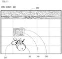
- FIG. 13 is an illustration view showing a non-limiting example game screen 200 in a case where a water place is determined as a river
- FIG. 14 is an illustration view showing a non-limiting example game screen 200 in a case where a water place is determined as a pond.
- FIG. 13 and FIG. 14 each shows a part of the water place.
- FIG. 13 When it is determined that the water place is a river, an animation showing a manner that the water flows is played-back as shown in FIG. 13 .
- the flow of the river is expressed by arrow marks in the game screen 200 shown in FIG. 13 , in fact, arrow marks are not displayed.
- a fish object 206 swims against to a flow of the river.
- a shadow of the fish object 206 is shown in FIG. 13 (in also FIG. 14 ).
- the player character 202 is caused to perform fishing using a fishing rod 212 based on an operation input of the player, if the player character 202 hangs down a thread 214 in a river, a float 216 attached to the thread 214 is moved to flow according to the flow of the river.
- the float 216 stops at a position according to a length of the thread 214 .
- kinds of fishes that can be caught in the river differ from kinds of fishes that can be caught in the pond.
- fishes that can be caught in the river may be a sweet fish, a char, a landlocked salmon, etc.
- the water does not flow as shown in FIG. 14 .
- the fish object 206 swims in the pond at random.
- the player character 202 is caused to perform fishing using a fishing rod 212 based on an operation input of the player, if the player character 202 hangs down a thread 214 in a pond, a float 216 floats at a position that the thread is hung down.
- kinds of fishes that can be caught in the pond are a goldfish, a crucian carp, a carp, a catfish, etc.
- a river or/and a pond is formed in advance in the game field in the virtual space. That is, water is placed also in an area (unit) that the ground is dug in advance.
- the player character 202 By causing the player character 202 to fill a whole or part of the area where the ground is dug in advance, it is possible to make a whole or part of a river or/and a pond formed in advance into the ground. In also this case, it is possible to deform the terrain.
- the player character 202 when causing the player character 202 to perform fishing based on an operation input of the player, different processing is performed for a river and for a pond. Accordingly, the player can fish a desired fish object 206 by causing the player character 202 to generate a river or a pond. That is, it is possible to enjoy different fishing in a river and a pond.
- the game screen 200 shown in FIG. 12 if the ground between a hole formed by digging the ground and a river is dug, it is possible to connect the hole formed by digging the ground to the river as shown in FIG. 15 . In this case, the hole dug by the player character 202 based on an operation input of the player becomes a part of the river.
- this water place is determined as a river.
- the water place is a river or a pond based on whether both of the area S of the water place and the distance (length) d from a water-place unit rendered a start point to a water-place unit rendered an end point set in the water place, satisfy the formula 1.
- such determination is made on the assumption that each of vertical length and horizontal length of one (1) unit is “1”, and the area of one (1) unit is “1”. Therefore, a distance between two units adjacent to each other vertically or horizontally is a distance between the centers of the two units, that is, “1”.
- the distance between the two units in the same water place means the number of the units that is the smallest value or the shortest distance out of distances traveled from the center of one unit of the two units to the center of the other unit by repeatedly moving to a unit adjacent vertically or horizontally, that is, up, down, left or right (i.e., moving one (1) by one (1) in distance) without moving on the ground.
- d 2 >4 S [Formula 1]
- the water place is a river (i.e., to have a flow of water) by comparing a parameter of the distance d between the start point and the end point both set in the water place with a parameter of the area S of the water place.
- a water-place unit rendered the start point and a water-place unit rendered the end point are set according to a first rule.
- a water-place unit rendered the start point is simply referred to as “start point” and a water-place unit rendered the end point is simply referred to as “end point”.
- the first rule includes the following four items (1) to (4). (1) A distance connecting two points (i.e., a distance between two units) needs to be greatest. (2) The start point needs to be located on a north-most side of the water place. (3) The end point needs to be located in a south-most side of the water place.
- an upper direction is set north
- a down direction is set south
- a left direction is set west
- a right direction is set east.
- FIG. 16A is an illustration view schematically showing a non-limiting example terrain divided into a plurality of units for describing a method of determining whether the water place is a river or a pond.
- FIG. 16B is an illustration view schematically showing another non-limiting example terrain divided into a plurality of units for describing a method of determining whether the water place is a river or a pond.
- a unit filled with gray is a ground (or land) unit
- a unit filled with white is a unit of the water place unit (hereinafter, referred to as “water-place unit”).
- water-place unit a unit of the water place unit
- the area S of the water place i.e., the number of the water-place units
- the distance d connecting the start point and the end point set according to the above-described first rule is “9”.
- the formula 1 since the formula 1 is not satisfied, it is determined that the water place is a pond.
- the area S of the water place i.e., the number of the water-place units
- the distance d connecting the start point and the end point set according to the above-described first rule is “10”.
- the formula 1 since the formula 1 is satisfied, it is determined that the water place is a river.
- a start point and an end point are set by a second rule different from the above-described first rule.
- the second rule includes following three items (a)-(c).
- (a) Water-place units connected to a bottom of waterfall are all rendered start points.
- (b) Water-place units connected to a top of waterfall are all rendered end points.
- (c) River units connected to brackish water area are all rendered end points.
- a start point and an end point are set according to the second rule. That is, when the water place formed by digging the ground by the player character 202 is connected to a water source such as a top of waterfall, a bottom of waterfall and a brackish water area, a start point and an end point are set according to the second rule regardless of whether a shape of the formed water place is a long shape.
- FIG. 17 is an illustration view schematically showing a non-limiting example terrain that includes a waterfall (top and bottom) and a brackish water area, and is divided into a plurality of units. Although a plurality of units constituting the top of waterfall, the bottom of waterfall and the brackish water area are respectively located in positions that are set in advance in the game field in the virtual space, these units may be located or changed by the player.
- a start point and an end point are set according to the second rule. That is, as shown in FIG. 17 , a plurality of water-place units adjacent to a lower side of the unit of the bottom of the waterfall are all set as start points according to the above-described item (a). Moreover, a plurality of water-place units adjacent to an upper side of the unit of the top of the waterfall are all set as end points according to the above-described item (b). Furthermore, a plurality of water-place units adjacent to an upper side of the unit of the brackish water area are all set as end points according to the above-described item (c).
- a flow of water is generated on the basis of the start point and the end point that are thus set as described above.
- a flow of water is dynamically generated based on a propagating energy.
- FIG. 18A is an illustration view showing a non-limiting example propagation manner of the outflow energy
- FIG. 18B is an illustration view showing a non-limiting example propagation manner of the inflow energy
- FIG. 18C is an illustration view showing a non-limiting example distribution manner of the outflow energy
- FIG. 18D is an illustration view showing another non-limiting example propagation manner of the outflow energy at a time of being reflected by a land
- FIG. 18E is an illustration view showing a further non-limiting example propagation manner of the outflow energy at a time of being reflected by an L-letter-shaped wall (or land).
- FIG. 18A - FIG. 18E a terrain including nine units of longitudinal three (3) units by lateral three (3) units is used.
- an upper left unit is called “first unit”
- a unit adjacent in the right to the first unit is called “second unit”
- a unit adjacent in the right to the second unit is called “third unit”, in FIG. 18A - FIG. 18E .
- a unit adjacent below to the first unit is called “fourth unit”
- a unit adjacent in the right to the fourth unit is called “fifth unit”
- a unit adjacent in the right to the fifth unit is called “sixth unit”, in FIG. 18A - FIG. 18E .
- a unit adjacent below to the fourth unit is called “seventh unit”
- a unit adjacent in the right to the seventh unit is called “eighth unit”
- a unit adjacent in the right to the eighth unit is called “ninth unit”, in FIG. 18A - FIG. 18E .
- the outflow energy is propagated in a direction of energy. That is, the outflow energy is propagated to a unit adjacent on the same side as the direction of energy at every time when a predetermined time period (one (1) second, in this embodiment) elapses.
- a predetermined time period one (1) second, in this embodiment
- the outflow energy in the fourth unit at the time t is propagated to the fifth unit at the time t+1.
- the outflow energy in the fifth unit at the time t+1 is propagated to the sixth unit at the time t+2.
- FIG. 18A also in FIG. 18B - FIG. 18E , only a propagated energy is indicated using arrow marks in order to describe the energy propagation, in fact, the energy is continuously propagated as long as the energy from an energy source (both of a outflow source and an inflow source) is not interrupted and the terrain is not deformed.
- an energy source both of a outflow source and an inflow source
- the energy is controlled so that it is not attenuated as a function of a distance from the energy source (both of the outflow source and the inflow source). This is for avoiding that the energy disappears before reaching an opposite stop and thus a flow of water is lost on the way when there is only one energy source and a relatively long water place is formed, for example.
- the inflow energy is propagated in a direction opposite to a direction of the energy. That is, the inflow energy is propagated to a unit adjacent on the opposite side to the direction of the energy at every time when a predetermined time period (one (1) second, in this embodiment) elapses.
- a predetermined time period one (1) second, in this embodiment
- the inflow energy in the sixth unit at the time t is propagated to the fifth unit at the time t+1.
- the inflow energy in the fifth unit at the time t+1 is propagated to the fourth unit at the time t+2.
- the energy is propagated in a direction of energy or in an opposite direction, but in a case of propagation in only each direction, in the area that width is made large on the way, the energy is no longer propagated to a unit of the portion that the width is made large. Therefore, in this embodiment, as shown in FIG. 18C , a part of energy is distributed to each of the units adjacent in the right and left in the propagation direction of energy.
- the outflow energy in the fourth unit at the time t is propagated to the fifth unit at the time t+1. At this time, the outflow energy is divided so that a part thereof is propagated to each of the first unit and the seventh unit.
- the energy to be propagated is basically controlled so as not to be attenuated.
- FIG. 18D and FIG. 18E are illustration views each showing a non-limiting example reflection manner of the energy in a case where a propagation destination of the energy is land (or the ground).
- the example of FIG. 18D shows a case where the land is formed to be extended right and left in a straight line in the seventh unit, the eighth unit and the ninth unit, and the outflow energy is propagated in a direction perpendicularly to the land.
- the example of FIG. 18E shows a case where the land is formed in an L-letter shape in the first unit, the fourth unit, the seventh unit, the eighth unit and the ninth unit, and the outflow energy is propagated in a direction perpendicularly to the land corresponding to a lateral bar of the L-letter.
- the land (or the ground) is located in the eighth unit to which the outflow energy is to be propagated from the fifth unit. Therefore, the outflow energy is reflected by the land. In this embodiment, the outflow energy is reflected (or propagated) in a direction along the land. Therefore, as shown in FIG. 18D , after t+1 seconds, the outflow energy is propagated to the fourth unit in the left direction, and propagated to the sixth unit in the right direction.
- the land (or the ground) is located in the eighth unit to which the outflow energy is propagated from the fifth unit. Therefore, the outflow energy is reflected by the land similar to a case shown in FIG. 18D . However, the land (or ground) is located in the fourth unit. Therefore, as shown in FIG. 18E , after t+1 seconds, the outflow energy is propagated to the sixth unit in the right direction.
- the outflow energy is propagated toward the bottom of the U-letter from the top of the U-letter, the outflow energy propagated to the land is made not to be reflected (propagated) in any directions. This is for avoiding that the outflow energy of a unit of a propagation source is canceled and resulting in an expression like a backflow.
- the propagation of the outflow energy and the propagation of the inflow energy in each of the water-place units constituting the water place are calculated, respectively. If the propagation of the energy is calculated, the propagation of the outflow energy and the propagation of the inflow energy are combined, and a flow of water is calculated based on the propagation of the combined energy. However, the flow of water is calculated for each water place. If the holes are not connected to each other, it is determined that water places are different from each other.
- FIG. 19A shows four water-place units U 1 -U 4 , and a direction of the energy of the flow of water in each of the water-place units U 1 -U 4 is indicated with a white arrow mark.
- a flow of water in each point within a range R enclosed with dotted lines is calculated (interpolated) by combining vectors set at center points of the four water-place units U 1 -U 4 .
- the vector set at the center point of each of the water-place units U 1 -U 4 is a vector having a direction that the energy is propagated in each of the water-place units U 1 -U 4 and a predetermined size (for example, “1”).
- a vector M is set at the center point of the water-place unit U 1
- a vector N is set at the center point of the water-place unit U 2
- a vector P is set at the center point of the water-place unit U 3
- a vector Q is set at the center point of the water-place unit U 4 .
- a vector that is, a flow of water at an arbitrary point X within the range R enclosed with dotted lines is calculated by combining the four vectors M, N, and P and Q.
- the sizes of the vectors M, N, P and Q are reduced as distances L 1 , L 2 , L 3 and L 4 with the point X are increased.
- a direction and a speed that the water flows are determined according to a direction and a size of a vector obtained by combining the vectors M, N, and P and Q (i.e., combined vector).
- the size of the vector is “1”
- a standard speed is set, and the speed is reduced as the size of the vector becomes smaller.
- the speed is not made larger than the standard speed.
- a flow of water in each of the water-place units constituting the water place that is, a direction and a speed that the water flows are calculated using the vectors set at the centers of the adjacent water-place units.
- the combined vector in an arbitrary point within a range K (an area of the L-letter) except a portion of a unit that the ground is set from the range R is calculated using the vectors set at the center points of three water-place units.
- a calculation method of a combined vector is the same as that of a case where the combined vector at an arbitrary point X within the range R is calculated, and is calculated except for a component of a vector set at the center point of the unit where the ground is set.
- FIG. 20A is an illustration view showing a non-limiting example distance map with respect to a start point in a plurality of water-place units constituting the water place.
- the distance map means a map that a distance to a water-place unit to be noted from a reference water-place unit is expressed by a numeral value.
- a water-place unit of the start point is set to a reference water-place unit, and a distance of this water-place unit of a start point itself is set to “0”. Since a distance between the adjacent two units is “1” as described above, a distance of a water-place unit adjacent to the water-place unit of the start point is set to “1”. A distance of a water-place unit adjacent to the water-place unit that the distance is set to “1” is set to “2”. A distance of a water-place unit adjacent to the water-place unit that the distance is set to “2” is set to “3”. By repeating this, the distances from the water-place unit of the start point are set to all the water-place units.
- FIG. 21A is an illustration view showing a non-limiting example distance map with respect to an end point in a plurality of water-place units constituting the water place.
- a water-place unit of the end point is set to a reference water-place unit, and a distance of this water-place unit of end point itself is set with “0”.
- the distance of a water-place unit adjacent to the water-place unit of the end point is set to “1”, and distances of respective water-place units are set similar to the distance map with respect to the start point shown in FIG. 20A .
- the initial values of the flows of water by the end point are set.
- the distance map with respect to the end point if the numerical values of the same distance are set to the adjacent water-place units, no flow of water is generated.
- a flow of water from the water-place unit having a large numeral value to the water-place unit having a small numeral value is generated.
- flows of water are generated as shown in FIG. 20B .
- the initial values of the flows of water by the start point and the initial values of the flows of water by the end point are set, these initial values are combined and an initial value of the flow of water of each of the water-place units in the water place is determined. Moreover, the flow of water of each point in each of the water-place units constituting the water place is calculated (or interpolated) similar to a case where FIG. 19A and FIG. 19B are shown.
- initial values of the flows of water in the water place are determined, and an animation that the water flows is played-back based on the determined initial values of the flows of water during a predetermined time period (30 frames, for example).
- a frame is a unit time period for updating a screen
- one (1) frame is 1/30 seconds in this embodiment. This is an example, and one (1) frame may be 1/60 seconds or 1/120 seconds.
- the flows of water based on propagation of the outflow energy and propagation of the inflow energy are calculated for each frame, flows of water based on the distance map is gradually changed to the flows of water based on the propagation of energy.
- the start point and the end point are newly set, and it is newly determined whether a shape of the water place that is deformed or newly formed according to change of the shape of the water place is a long shape.
- propagation of the inflow energy from the newly set start point is calculated and propagation of the outflow energy from the newly set end point is calculated.
- a flow of water is calculated according to propagation of the energy obtained by combining the propagation of the inflow energy and the propagation of the outflow energy.
- the flow of water for each point is controlled so that the flow of water is changed gradually.
- FIG. 22 is an illustration view showing a non-limiting example memory map 850 of the DRAM 85 shown in FIG. 6 .
- the DRAM 85 includes a program storage area 852 and a data storage area 854 .
- the program storage area 852 is stored with a program of a game application (i.e., game program).
- the game program includes a main processing program 852 a , an image generation program 852 b , an operation detection program 852 c , a character control program 852 d , a background object change program 852 e , a shape determination program 852 f , a point setting program 852 g , a flow calculation program 852 h , an image display program 852 i , etc.
- a function of displaying images such as a generated game image is a function that the main body apparatus 2 is provided with. Therefore, the image display program 852 i is not included in the game program.
- a part or whole of each of the programs 852 a - 852 h is read from the flash memory 84 or/and a storage medium attached to the slot 23 so as to be stored in the DRAM 85 .
- a part or whole of each of the programs 852 a - 852 h may be acquired from other computers capable of performing communication with the main body apparatus 2 .
- the image display program 852 i is read from the flash memory 84 so as to be stored in the DRAM 85 .
- the main processing program 852 a is a program for executing overall game processing of a virtual game of this embodiment.
- the image generation program 852 b is a program for generating, using image generation data 854 b , display image data corresponding to various kinds of images such as a game image.
- the operation detection program 852 c is a program for acquiring the operation data 854 a from the left controller 3 or/and the right controller 4 . That is, the operation data 854 a according to an operation input by the player is acquired.
- the character control program 852 d is a program for controlling an action or motion of the player character 202 based on an operation input of the player, and controlling an action or motion of the non-player character regardless of an operation input of the player.
- the background object change program 852 e is a program, mainly in this embodiment, for digging the terrain according to a digging action of the player character 202 and for filling a hole or a water place according to a burying action of player character 202 . That is, the background object change program 852 e is a program for mainly deforming the terrain according to an action of the player character 202 . Therefore, according to the background object change program 852 e , a house, a wall or a bridge may be built or a house, a wall or a bridge may be removed.
- the shape determination program 852 f is a program for determining whether a shape of the water place is a long shape when the terrain is deformed.
- the point setting program 852 g is a program for setting a start point or/and an end point according to a predetermined rule (i.e., the first rule or second rule) in a plurality of water-place units constituting the water place.
- the flow calculation program 852 h is a program for calculating a flow of water (a direction and a speed of a flow of water in each point) in each water-place unit based on outflow energy and inflow energy in the water place. Moreover, the flow calculation program 852 h is also a program for calculating the initial values of the flows of water when the player character enters a scene of the water place by generating the distance map with respect to the start point and the distance map with respect to the end point, and combining these distance maps.
- the image display program 852 i is a program for outputting to a display the display image data generated according to the image generation program 852 b . Therefore, the images (i.e., the game screen 200 , etc.) corresponding to the display image data are displayed on the display such as the display 12 .
- the program storage area 852 is further stored with a sound output program for outputting a sound such as a BGM, a communication program for performing communication with other apparatuses, a backup program for storing data in a nonvolatile storage medium such as the flash memory 84 , etc.
- the data storage area 854 is stored with operation data 854 a , image generation data 854 b , current position data 854 c , background object data 854 d , shape determination data 854 e , point data 854 f , flow data 854 g , a shortening flag 854 h , etc.
- the operation data 854 a is operation data received from the left controller 3 or/and the right controller 4 .
- the main body apparatus 2 when the main body apparatus 2 receives the operation data from both the left controller 3 and the right controller 4 , the main body apparatus 2 stores the operation data 854 a classified into the left controller 3 and the right controller 4 , respectively.
- the image generation data 854 b is data required for generating an image, such as polygon data and texture data.
- the texture data includes data for displaying the flow of water by an animation.
- the current position data 854 c is data of the position coordinates of the characters or the objects capable of moving in the virtual space at the current frame, such as the player character 202 and the non-player characters including the fish object 206 , etc.
- the background object data 854 d is data about the background object 204 arranged in the virtual space, specifically, including data of the polygon and the texture constituting the background object 204 , and data of the position coordinates of arranging position of the background object 204 in the virtual space.
- the shape determination data 854 e is data about a result of having determined whether the shape of the water place formed or deformed by the player character 202 is a long shape. When there are two or more water places formed or deformed by the player character 202 , a result determined for each water place is stored.
- the point data 854 f is data indicating identification information about the start point and the end point that are set according to the point setting program 852 g and position coordinates data of the start point and the end point. However, when there are two or more water places, for each of the water places, the identification information about the start point and the end point and data of the position coordinates of the start point and the end point are stored as the point data 854 f.
- the flow data 854 g is data about the flow of water (the direction and the speed that the water flows for each point) for each water-place unit, calculated according to the flow calculation program 852 h.
- the shortening flag 854 h is a flag for determining whether the time in a state where the flow of water is not changed with time, that is, the time until the flow of water reaches a steady state should be shortened. When shortening time until the flow of water reaches the steady state, the shortening flag 854 h is turned on, and when not shortening time until the flow of water reaches the steady state, the shortening flag 854 h is turned off.
- the data storage area 854 is stored, for executing the game program, with other data required, and provided with other flags and other timers (counters).
- FIG. 23 is a flowchart showing non-limiting example processing of the game program (overall game processing) by the processor 81 (or computer) of the main body apparatus 2 .
- the overall game processing is described using FIG. 23 in the following, duplicate description for a step(s) executing the same processing will be omitted.
- processing of respective steps of the flowchart shown in FIG. 23 are mere examples, and if the same or similar result is obtainable, an order of the respective steps may be exchanged.
- the processor 81 basically executes the processing of each step of the flowcharts shown in FIG. 23 - FIG. 26 ; however, some steps may be executed by a processor(s) or/and a dedicated circuit(s) other than the processor 81 .
- the processor 81 executes a boot program stored in a boot ROM not shown, whereby respective units including the DRAM 85 , etc. are initialized.
- the main body apparatus 2 starts the overall game processing when the execution of the game program of this embodiment is instructed by the user.
- the processor 81 executes initial processing in a step S 1 .
- the processor 81 constructs a virtual space for generating and displaying the game screen 200 , and arranges the player character 202 , the non-player character(s) and the background object(s) 204 that appear in this virtual space at their initial positions.
- the processor 81 sets the initial values of various parameters used by game control processing (S 5 ).
- the processor 81 acquires the operation data transmitted from the controller(s) ( 3 , 4 ) in a step S 3 , and executes the game control processing in a step S 5 .
- an arbitrary actions such as moving of the player character 202 according to the operation data is performed.
- an arbitrary action such as moving of the non-player character is performed according to the game program.
- an action that the fish object 206 moves i.e., swims
- the fish object 206 is moved against to the flow of the river, and if the water place is a pond, the fish object 206 is moved at random.
- a next step S 7 the processor 81 generates the game image to be displayed on the display 12 .
- the processor 81 generates game image data by reading the data indicating a result of the game control processing in the step S 5 and the image generation data 854 b from the DRAM 85 .
- the processor 81 generates a game sound to be output to the speaker 88 .
- the processor 81 generates game sound data by reading the data indicating a result of the game control processing in the step S 5 and the sound data from the DRAM 85 .
- the game image data generated in the step S 7 is output to the display 12 in a step S 11
- the game sound data generated in the step S 9 is output to the speaker 88 through the codec circuit 87 in a step S 13 .
- the game sound data may be output to the sound input/output terminal 25 .
- step S 15 it is determined, in a step S 15 , whether the game is to be ended.
- the determination in the step S 15 is executed based on, for example, whether the game is over, or whether the player gives an instruction to stop the game. If “NO” is determined in the step S 15 , that is, if the game is not to be ended, the process returns to the step S 3 . If “YES” is determined in the step S 15 , that is, if the game is to be ended, the overall game processing is terminated.
- FIG. 24 - FIG. 26 are flow charts showing non-limiting example game image generation processing shown in FIG. 23 of the processor 81 (or computer) of the main body apparatus 2 .
- the processor 81 determines, in a step S 21 , whether the player character 202 enters a scene of the water place. If “NO” is determined in the step S 21 , that is, if not entering the scene of the water place, the process proceeds to a step S 31 described later. On the other hand, if “YES” in the step S 21 , that is, if entering the scene of the water place, it is determined, in a step S 23 , whether determination processing on whether there is a flow of water of a water place in the entered scene of the water place (hereinafter, referred to as the “water place concerned”) is executed.
- the processor 81 determines whether it is determined on whether a shape of the water place concerned is a long shape, with reference to the shape determination data 854 e.
- step S 23 determines whether there is a flow of water in the water place concerned. If “YES” is determined in the step S 23 , that is, if it is determined whether there is a flow of water in the water place concerned, the process proceeds to a step S 27 . On the other hand, if “NO” is determined in the step S 23 , that is, if it is not determined whether there is a flow of water in the water place concerned, it is determined, in a step S 25 , whether a start point and an end point are set in the water place concerned. That is, it is determined whether the water place concerned includes the water source located in advance in the game field.
- step S 25 determines whether “NO” is determined in the step S 25 , that is, if a start point and an end point are not set in the water place concerned. If “NO” is determined in the step S 25 , that is, if a start point and an end point are not set in the water place concerned, the process proceeds to a step S 53 shown in FIG. 25 .
- step S 27 the distance map with respect to the start point and the distance map with respect to the end point are calculated and the initial values of the flow of water are calculated.
- step S 29 the initial value of the flow of water is set for each of the water-place units, and the process proceeds to a step S 51 .
- step S 31 it is determined, in the step S 31 , whether the player character 202 exists in the scene of the water place. If “NO” is determined in the step S 31 , that is, if the player character 202 does not exist in the scene of the water place, the process proceeds to the step S 53 shown in FIG. 25 . On the other hand, if “YES” is determined in the step S 31 , that is, if the player character 202 exists in the scene of the water place, it is determined, in a step S 33 shown in FIG. 25 , whether the ground is dug or filled. That is, processor 81 determines whether the background object 204 is changed (i.e., whether the terrain is deformed) by the player character 202 .
- step S 33 If “NO” is determined in the step S 33 , that is, if the ground is not dug or filled, the process proceeds to a step S 55 shown in FIG. 26 .
- step S 35 it is determined, in a step S 35 , whether the water place concerned is connected to the area where the start point and the end point are set (i.e., a river where the water source is located).
- step S 35 determines whether “YES” is connected to the area where the start point and the end point are set. If “YES” is determined in the step S 35 , that is, the water place concerned is connected to the area where the start point and the end point are set, in a step S 37 , a start point and an end point are set according to the second rule, and the process proceeds to the step S 51 .
- step S 35 determines whether “NO” is determined in the step S 35 , if the water place concerned is not connected to the area where the start point and the end point are set.
- the shortening flag 854 h is turned on in a step S 39 , and a first count value is set to “1” in a step S 41 .
- the first count value is a variable for counting the predetermined period that the flow of water for each unit is calculated (in this embodiment, one (1) second (30 frames)), in order to shorten the time until reaching the steady state.
- a start point and an end point are set according to the first rule.
- the shape determination processing is executed.
- the processor 81 calculates the area S of the water place concerned and the distance d from the start point to the end point, and determines whether the formula 1 is satisfied.
- a result of determination in the step S 45 is stored. That is, the processor 81 stores the shape determination data 854 e about the water place concerned.
- a shape of the water place concerned is a long shape. If “NO” is determined in the step S 49 , that is, if a shape of the water place concerned is not a long shape, the process proceeds to the step S 53 . On the other hand, if “YES” is determined in the step S 49 , that is, if a shape of the water place concerned is a long shape, it is determined that there is a flow of water, and in the step S 51 , a flow of the water in the water place concerned is calculated for each unit, and the process proceeds to the step S 53 .
- the drawing processing in the step S 53 the drawing processing is executed, and the game image generation processing of the game image is ended, and the process returns to the overall game processing.
- the processor 81 draws not only the water place concerned but also the player character 202 , the background objects 204 other than the water place concerned, the fish object 206 , etc.
- the fishing rod 212 , the thread 214 and the float 216 are also drawn.
- playback processing that plays-back an animation of the texture of water is performed.
- step S 55 it is determined, in the step S 55 , whether the shortening flag 854 h is turned on. If “YES” is determined in the step S 55 , that is, if the shortening flag 854 h is turned on, the first count value is incremented by one (1) in a step S 57 , and it is determined, in a step S 59 , whether the first count value is equal to or more than “30”. That is, it is determined whether the predetermined time period for shortening the time until the flow of water reaches a steady state elapses.
- step S 59 If “NO” is determined in the step S 59 , that is, if the first count value does not reach “30”, the process proceeds to the step S 51 shown in FIG. 25 . On the other hand, if “YES” is determined in the step S 59 , that is, if the first count value is equal to or more than “30”, the shortening flag 854 h is tuned off in a step S 61 , and then, the process proceeded to the step S 53 .
- the second count value is incremented by one (1) in a step S 63 , and it is determined, in a step S 65 , whether the second count value is equal to or more than “30”.
- the second count value is a variable for counting the number of the frames corresponding to one (1) second, in order to propagate the outflow energy and the inflow energy to the adjacent units for every one (1) second. If “NO” determined in the step S 65 , that is, if the second count value is less than “30”, the process proceeded to the step S 53 .
- step S 65 determines whether “YES” is equal to or more than “30” or the second count value is equal to or more than “30”
- the second count value is set to “0” in a step S 67 , and the process proceeds to the step S 51 .
- this embodiment it is possible to deform the terrain by causing the player character to dig or fill the ground based on an operation input of the player, and the water is placed in the hole that is formed by digging the ground to form the water place, and the flow of water is generated according to whether a shape of the water place is a long shape, and therefore, it is possible to deform the terrain and generate the flow of water in the deformed terrain.
- the water (object) is placed as a fluid object in the hole and the water is allowed to flow when it is determined that a shape of the water place (hole) is a long shape, but the fluid object does not need to be limited to the water object.
- another fluid object such as a flow of lava (or magma), sand (sand flow) and clouds.
- sand is not a fluid
- the sand may be treated as a fluid, and this embodiment can be applied to such a case.
- the ground is dug or filled using the shovel in this embodiment, it does not need to be limited to this.
- the ground may be deformed or the ground may simply disappear according to an operation input of the player or a game event.
- the ground can be dug by blasting. However, by blasting a rock buried in the ground, the rock may disappear and a hole may appear.
- the game system 1 is shown as an example of an information processing system in this embodiment, the structure thereof should not be limited, and it is possible to adopt other structure.
- the above-described “computer” is a single computer (specifically, processor 81 ) in the above-described embodiment, the “computer” may be a plurality of computers in another embodiment.
- the above-described “computer” may be (a plurality of) computers provided on a plurality of devices, and more specifically, the above-described “computer” may be constituted by the processor 81 of the main body apparatus 2 and communication control units (microprocessors) 101 and 111 provided on the controllers.
- the game control processing, the game image generation processing and the game sound generation processing shown in FIG. 23 - FIG. 26 may be performed in a server on a network such as the internet.
- the processor 81 of the main body apparatus 2 transmits the operation data received from the left controller 3 and the right controller 4 to the above-described server via the network communication section 82 and the network, receives results (that is, game image data and game sound data) of the game control processing, the game image generation processing and the game sound generation processing that are executed by the server, and displays the game image on the display 12 and makes the game sound be output from the speaker 88 . That is, it is possible to constitute an information processing system including the game system 1 shown in the above-described embodiment and the server on the network.
- the game image can also be displayed on a stationary monitor (for example, television monitor) by connecting the main body apparatus 2 to the stationary monitor via a cradle.
- a stationary monitor for example, television monitor
- an operation portion having operation buttons and analog sticks similar to those of the left controller 3 and the right controller 4 is provided integrally with the main body apparatus 2 or further electronic equipment capable of executing a game program.
- the further electronic equipment corresponds to smartphones, tablet PCs or the like.
- an operation portion may constitute with software keys.
- the left controller 3 and the right controller 4 may be integrally constituted by coupling them using connecting members to each other to be used as a single controller.
Abstract
Description
d 2>4S [Formula 1]
Claims (22)
Applications Claiming Priority (3)
| Application Number | Priority Date | Filing Date | Title |
|---|---|---|---|
| JPJP2019-100479 | 2019-05-29 | ||
| JP2019-100479 | 2019-05-29 | ||
| JP2019100479A JP7129947B2 (en) | 2019-05-29 | 2019-05-29 | GAME PROGRAM, GAME SYSTEM, GAME DEVICE AND GAME CONTROL METHOD |
Publications (2)
| Publication Number | Publication Date |
|---|---|
| US20200376382A1 US20200376382A1 (en) | 2020-12-03 |
| US11219830B2 true US11219830B2 (en) | 2022-01-11 |
Family
ID=73546278
Family Applications (1)
| Application Number | Title | Priority Date | Filing Date |
|---|---|---|---|
| US16/731,185 Active 2040-01-15 US11219830B2 (en) | 2019-05-29 | 2019-12-31 | Storage medium, game system, game apparatus and game controlling method |
Country Status (2)
| Country | Link |
|---|---|
| US (1) | US11219830B2 (en) |
| JP (1) | JP7129947B2 (en) |
Families Citing this family (2)
| Publication number | Priority date | Publication date | Assignee | Title |
|---|---|---|---|---|
| JP7083380B2 (en) * | 2020-09-28 | 2022-06-10 | グリー株式会社 | Computer programs, methods and server equipment |
| JP7138691B2 (en) * | 2020-12-08 | 2022-09-16 | 株式会社スクウェア・エニックス | Video game processing program and video game processing system |
Citations (5)
| Publication number | Priority date | Publication date | Assignee | Title |
|---|---|---|---|---|
| US20060003832A1 (en) * | 2004-05-13 | 2006-01-05 | Sierra Design Group, A Nevada Corporation | Path or flow based bonus game |
| US20060258444A1 (en) | 2005-05-13 | 2006-11-16 | Nintendo Co., Ltd. | Storage medium having game program stored thereon and game apparatus |
| US20070265053A1 (en) * | 2005-11-22 | 2007-11-15 | Cyberscan Technology, Inc. | Regulated gaming - staging multi-act games |
| US7695367B2 (en) * | 2005-05-13 | 2010-04-13 | Nintendo Co., Ltd. | Storage medium having game program stored thereon and game apparatus |
| US20140080558A1 (en) * | 2012-09-17 | 2014-03-20 | King.Com Limited | Method for implementing a computer game |
Family Cites Families (3)
| Publication number | Priority date | Publication date | Assignee | Title |
|---|---|---|---|---|
| JP2001079269A (en) | 1999-09-10 | 2001-03-27 | Sony Computer Entertainment Inc | Game system and information memory medium |
| JP2002306840A (en) | 2001-04-19 | 2002-10-22 | Taito Corp | Character item generation game machine capable of preparing parameter by two dimensional shape |
| JP4774459B2 (en) | 2009-11-12 | 2011-09-14 | 株式会社ソニー・コンピュータエンタテインメント | Game control program |
-
2019
- 2019-05-29 JP JP2019100479A patent/JP7129947B2/en active Active
- 2019-12-31 US US16/731,185 patent/US11219830B2/en active Active
Patent Citations (6)
| Publication number | Priority date | Publication date | Assignee | Title |
|---|---|---|---|---|
| US20060003832A1 (en) * | 2004-05-13 | 2006-01-05 | Sierra Design Group, A Nevada Corporation | Path or flow based bonus game |
| US20060258444A1 (en) | 2005-05-13 | 2006-11-16 | Nintendo Co., Ltd. | Storage medium having game program stored thereon and game apparatus |
| JP2006314633A (en) | 2005-05-13 | 2006-11-24 | Nintendo Co Ltd | Game program and game machine |
| US7695367B2 (en) * | 2005-05-13 | 2010-04-13 | Nintendo Co., Ltd. | Storage medium having game program stored thereon and game apparatus |
| US20070265053A1 (en) * | 2005-11-22 | 2007-11-15 | Cyberscan Technology, Inc. | Regulated gaming - staging multi-act games |
| US20140080558A1 (en) * | 2012-09-17 | 2014-03-20 | King.Com Limited | Method for implementing a computer game |
Also Published As
| Publication number | Publication date |
|---|---|
| JP7129947B2 (en) | 2022-09-02 |
| JP2020192168A (en) | 2020-12-03 |
| US20200376382A1 (en) | 2020-12-03 |
Similar Documents
| Publication | Publication Date | Title |
|---|---|---|
| US11484794B2 (en) | Game device, control method, and non-transitory computer-readable medium | |
| US20180191990A1 (en) | Projection system | |
| JP5596414B2 (en) | GAME PROGRAM, GAME SYSTEM, GAME DEVICE, AND GAME CONTROL METHOD | |
| US10525354B2 (en) | Game apparatus, game controlling method and storage medium for determining a terrain based on a distribution of collision positions | |
| US20170189797A1 (en) | Interactive game apparatus and toy construction system | |
| US11872475B2 (en) | Storage medium, information processing system, information processing apparatus and game controlling method involving linkable player character and sub-character | |
| US11219830B2 (en) | Storage medium, game system, game apparatus and game controlling method | |
| WO2021147468A1 (en) | Method and apparatus for virtual character control in virtual environment, and device and medium | |
| JP2001009156A (en) | Recording medium readable by computer, display control method of game, and game device | |
| JP2016159118A (en) | Program and server system | |
| US10525356B2 (en) | Storage medium, game apparatus, game system and game control method | |
| US11628365B2 (en) | Information processing system, storage medium, information processing apparatus and information processing method | |
| JP2022552752A (en) | Screen display method and device for virtual environment, and computer device and program | |
| US20120306854A1 (en) | Storage medium, image processing apparatus, image processing method, and image processing system | |
| US10297090B2 (en) | Information processing system, apparatus and method for generating an object in a virtual space | |
| US10967265B2 (en) | Storage medium, game system, game apparatus and game controlling method | |
| JP7371199B1 (en) | Game program, game system, game device, and game control method | |
| US20240033634A1 (en) | Storage medium, game system and game control method | |
| US9675887B2 (en) | Object display device | |
| US20240033635A1 (en) | Storage medium, game system and game control method | |
| US20240123359A1 (en) | Storage medium, game system and game control method | |
| JP2019187564A (en) | Game device, control method, and control program | |
| JP7313605B2 (en) | Game device, control method and control program | |
| US20240082730A1 (en) | Storage medium storing game program, game system, game apparatus, and game processing method | |
| JP2021007788A (en) | Game device, control method, and control program |
Legal Events
| Date | Code | Title | Description |
|---|---|---|---|
| AS | Assignment |
Owner name: NINTENDO CO., LTD., JAPAN Free format text: ASSIGNMENT OF ASSIGNORS INTEREST;ASSIGNORS:HIROMATSU, KOTARO;ITO, YOSHIHIKO;TAKAHASHI, KOJI;REEL/FRAME:051391/0168 Effective date: 20190820 |
|
| FEPP | Fee payment procedure |
Free format text: ENTITY STATUS SET TO UNDISCOUNTED (ORIGINAL EVENT CODE: BIG.); ENTITY STATUS OF PATENT OWNER: LARGE ENTITY |
|
| STPP | Information on status: patent application and granting procedure in general |
Free format text: DOCKETED NEW CASE - READY FOR EXAMINATION |
|
| STPP | Information on status: patent application and granting procedure in general |
Free format text: NON FINAL ACTION MAILED |
|
| STPP | Information on status: patent application and granting procedure in general |
Free format text: RESPONSE TO NON-FINAL OFFICE ACTION ENTERED AND FORWARDED TO EXAMINER |
|
| STPP | Information on status: patent application and granting procedure in general |
Free format text: FINAL REJECTION MAILED |
|
| STCV | Information on status: appeal procedure |
Free format text: NOTICE OF APPEAL FILED |
|
| STPP | Information on status: patent application and granting procedure in general |
Free format text: RESPONSE TO NON-FINAL OFFICE ACTION ENTERED AND FORWARDED TO EXAMINER |
|
| STPP | Information on status: patent application and granting procedure in general |
Free format text: NOTICE OF ALLOWANCE MAILED -- APPLICATION RECEIVED IN OFFICE OF PUBLICATIONS |
|
| STPP | Information on status: patent application and granting procedure in general |
Free format text: PUBLICATIONS -- ISSUE FEE PAYMENT VERIFIED |
|
| STCF | Information on status: patent grant |
Free format text: PATENTED CASE |