US11216116B2 - Control method and terminal - Google Patents
Control method and terminal Download PDFInfo
- Publication number
- US11216116B2 US11216116B2 US16/755,343 US201816755343A US11216116B2 US 11216116 B2 US11216116 B2 US 11216116B2 US 201816755343 A US201816755343 A US 201816755343A US 11216116 B2 US11216116 B2 US 11216116B2
- Authority
- US
- United States
- Prior art keywords
- report point
- point coordinates
- capacitance
- current frame
- frame
- Prior art date
- Legal status (The legal status is an assumption and is not a legal conclusion. Google has not performed a legal analysis and makes no representation as to the accuracy of the status listed.)
- Active, expires
Links
Images


Classifications
-
- G—PHYSICS
- G06—COMPUTING; CALCULATING OR COUNTING
- G06F—ELECTRIC DIGITAL DATA PROCESSING
- G06F3/00—Input arrangements for transferring data to be processed into a form capable of being handled by the computer; Output arrangements for transferring data from processing unit to output unit, e.g. interface arrangements
- G06F3/01—Input arrangements or combined input and output arrangements for interaction between user and computer
- G06F3/03—Arrangements for converting the position or the displacement of a member into a coded form
- G06F3/041—Digitisers, e.g. for touch screens or touch pads, characterised by the transducing means
- G06F3/0416—Control or interface arrangements specially adapted for digitisers
- G06F3/0418—Control or interface arrangements specially adapted for digitisers for error correction or compensation, e.g. based on parallax, calibration or alignment
- G06F3/04186—Touch location disambiguation
-
- G—PHYSICS
- G06—COMPUTING; CALCULATING OR COUNTING
- G06F—ELECTRIC DIGITAL DATA PROCESSING
- G06F3/00—Input arrangements for transferring data to be processed into a form capable of being handled by the computer; Output arrangements for transferring data from processing unit to output unit, e.g. interface arrangements
- G06F3/01—Input arrangements or combined input and output arrangements for interaction between user and computer
- G06F3/03—Arrangements for converting the position or the displacement of a member into a coded form
- G06F3/041—Digitisers, e.g. for touch screens or touch pads, characterised by the transducing means
- G06F3/0416—Control or interface arrangements specially adapted for digitisers
- G06F3/0418—Control or interface arrangements specially adapted for digitisers for error correction or compensation, e.g. based on parallax, calibration or alignment
-
- G—PHYSICS
- G06—COMPUTING; CALCULATING OR COUNTING
- G06F—ELECTRIC DIGITAL DATA PROCESSING
- G06F3/00—Input arrangements for transferring data to be processed into a form capable of being handled by the computer; Output arrangements for transferring data from processing unit to output unit, e.g. interface arrangements
- G06F3/01—Input arrangements or combined input and output arrangements for interaction between user and computer
- G06F3/03—Arrangements for converting the position or the displacement of a member into a coded form
- G06F3/041—Digitisers, e.g. for touch screens or touch pads, characterised by the transducing means
- G06F3/044—Digitisers, e.g. for touch screens or touch pads, characterised by the transducing means by capacitive means
-
- G—PHYSICS
- G06—COMPUTING; CALCULATING OR COUNTING
- G06F—ELECTRIC DIGITAL DATA PROCESSING
- G06F3/00—Input arrangements for transferring data to be processed into a form capable of being handled by the computer; Output arrangements for transferring data from processing unit to output unit, e.g. interface arrangements
- G06F3/01—Input arrangements or combined input and output arrangements for interaction between user and computer
- G06F3/048—Interaction techniques based on graphical user interfaces [GUI]
- G06F3/0487—Interaction techniques based on graphical user interfaces [GUI] using specific features provided by the input device, e.g. functions controlled by the rotation of a mouse with dual sensing arrangements, or of the nature of the input device, e.g. tap gestures based on pressure sensed by a digitiser
- G06F3/0488—Interaction techniques based on graphical user interfaces [GUI] using specific features provided by the input device, e.g. functions controlled by the rotation of a mouse with dual sensing arrangements, or of the nature of the input device, e.g. tap gestures based on pressure sensed by a digitiser using a touch-screen or digitiser, e.g. input of commands through traced gestures
Definitions
- Example embodiments of the present invention relate to the field of terminals, and in particular, to a control method and a terminal.
- a touchscreen panel is widely used due to advantages such as high sensitivity and a high response speed, and in particular, brings good user experience to a user in a field of intelligent terminals, such as a mobile phone.
- TP touchscreen panel
- a terminal may perform a calculation and determine the unintentional tapping as a flick operation of the user. Consequently, user experience is affected.
- Example embodiments of the present invention provide a control method and a terminal, so that a user operation behavior is determined by using a capacitance signal on a terminal touchscreen and report point data on the touchscreen, and a problem that a user unintentionally triggers flicking is resolved.
- control method may include:
- the input information includes a capacitance signal and report point coordinates that are generated when a user performs an operation on a terminal screen;
- report point coordinates in a previous frame as report point coordinates in a current frame if it is determined that a capacitance signal in the current frame and a capacitance signal in the previous frame that are in the input information meet a preset condition; or using report point coordinates in a previous frame as report point coordinates in a current frame if it is determined that the report point coordinates in the current frame and the report point coordinates in the previous frame that are in the input information meet a preset condition, to suppress flicking caused by an unintentional operation of the user.
- the capacitance signal includes a strength value of a capacitance bright spot
- the strength value of the capacitance bright spot is data corresponding to each element in the capacitance bright spot
- each element is corresponding to a rectangular area at a corresponding position on the terminal screen
- the using report point coordinates in a previous frame as report point coordinates in a current frame if it is determined that a capacitance signal in the current frame and a capacitance signal in the previous frame that are in the input information meet a preset condition includes:
- a peak ratio, a maximum value in sums of strength values of the capacitance bright spot, and a maximum value of the capacitance bright spot meets/meet a preset condition, using the report point coordinates in the previous frame as the report point coordinates in the current frame; or if it is determined that a peak ratio, a maximum value in sums of strength values of the capacitance bright spot, a maximum value of the capacitance bright spot, and a report point status meet a preset condition, using the report point coordinates in the previous frame as the report point coordinates in the current frame.
- the maximum value of the capacitance bright spot is a maximum value in strength values corresponding to a plurality of elements in the capacitance bright spot.
- the peak ratio is a ratio of a maximum value of a capacitance bright spot in the current frame to a maximum value of a capacitance bright spot in the previous frame.
- the maximum value in the sums of the strength values of the capacitance bright spot is a maximum value in sums of data that is of four adjacent elements and that includes the maximum value in the strength values of the capacitance bright spot.
- the report point coordinates in the previous frame are used as the report point coordinates in the current frame.
- the capacitance signal further includes a major axis value and a minor axis value of a capacitance bright spot
- the using report point coordinates in a previous frame as report point coordinates in a current frame if it is determined that a capacitance signal in the current frame and a capacitance signal in the previous frame that are in the input information meet a preset condition includes:
- the report point coordinates in the previous frame are used as the report point coordinates in the current frame.
- i represents the current frame, i is a positive integer greater than 1, and the axis change value meets the following formula:
- Axis ⁇ ⁇ change ⁇ ⁇ value ( Major ⁇ ⁇ axis ⁇ ⁇ value ⁇ ⁇ in ⁇ ⁇ a ⁇ ⁇ current ⁇ ⁇ frame - Major ⁇ ⁇ axis ⁇ ⁇ value ⁇ ⁇ in ⁇ ⁇ a ⁇ ⁇ previous ⁇ ⁇ frame ) 2 + ( Minor ⁇ ⁇ axis ⁇ ⁇ value ⁇ ⁇ in ⁇ ⁇ the ⁇ ⁇ current ⁇ ⁇ frame - Minor ⁇ ⁇ axis ⁇ ⁇ value ⁇ ⁇ in ⁇ ⁇ the ⁇ ⁇ previous ⁇ ⁇ frame ) 2 .
- the using report point coordinates in a previous frame as report point coordinates in a current frame if it is determined that the report point coordinates in the current frame and report point coordinates in a first frame that are in the input information meet a preset condition includes:
- the flicking distance is obtained by subtracting an unintentional flicking distance from a distance between the report point coordinates in the previous frame and the report point coordinates in the current frame, and the unintentional flicking distance is a sum of all unintentional flicking distances from the previous frame to the current frame.
- the report point coordinates in the previous frame are used as the report point coordinates in the current frame.
- the using report point coordinates in a previous frame as report point coordinates in a current frame if it is determined that a capacitance signal in the current frame and a capacitance signal in the previous frame that are in the input information meet a preset condition includes:
- the first capacitance signal change value is a change value of the capacitance signal in the current frame relative to the capacitance signal in the previous frame in a movement direction of a gravity center of a capacitance bright spot
- the second capacitance signal change value is a change value of the capacitance signal in the current frame relative to the capacitance signal in the previous frame in a direction opposite to the movement direction of the gravity center of the capacitance bright spot
- a third capacitance change value is an overall capacitance signal change value used for movement of the gravity center of the capacitance bright spot
- the ratio is a ratio of displacement of the gravity center of the capacitance bright spot to a movement distance of the gravity center of the capacitance bright spot in a specific time period.
- the report point coordinates in the previous frame are used as the report point coordinates in the current frame, and the preset condition includes:
- both of the first capacitance signal change value and the second capacitance signal change value are greater than zero, and the first capacitance signal change value and the second capacitance signal change value are greater than preset thresholds respectively; or both of the first capacitance signal change value and the second capacitance signal change value are less than zero, and the first capacitance signal change value and the second capacitance signal change value are less than preset thresholds respectively; or the first capacitance signal change value is greater than zero, the second capacitance signal change value is less than zero, and the movement efficiency is greater than a preset threshold; or both of an absolute value of the first capacitance signal change value and an absolute value of the second capacitance signal change value are less than a preset threshold.
- control method further includes:
- the compensating the report point coordinates in the current frame and report point coordinates after the current frame includes:
- stepX, stepY or (offsetRatio x ⁇ x, offsetRatio x ⁇ y), where stepX and offsetRatio x ⁇ x each are a compensation amount of the coordinates in each frame in the x direction, and stepY and offsetRatio x ⁇ y each are a compensation amount in the y direction.
- stepX and offsetRatio x ⁇ x each are a compensation amount of the coordinates in each frame in the x direction
- stepY and offsetRatio x ⁇ y each are a compensation amount in the y direction.
- a terminal may include:
- a processing unit configured to obtain input information, where the input information includes a capacitance signal and report point coordinates that are generated when a user performs an operation on a terminal screen.
- the processing unit is further configured to: use report point coordinates in a previous frame as report point coordinates in a current frame if it is determined that a capacitance signal in the current frame and a capacitance signal in the previous frame that are in the input information meet a preset condition; or use report point coordinates in a previous frame as report point coordinates in a current frame if it is determined that the report point coordinates in the current frame and report point coordinates in a first frame that are in the input information meet a preset condition, to suppress flicking caused by an unintentional operation of the user.
- the capacitance signal includes a strength value of a capacitance bright spot
- the strength value of the capacitance bright spot is data corresponding to each element in the capacitance bright spot
- each element is corresponding to a rectangular area at a corresponding position on the terminal screen
- the processing unit uses the report point coordinates in the previous frame as the report point coordinates in the current frame; or if it is determined that a peak ratio, a maximum value in sums of strength values of the capacitance bright spot, a maximum value of the capacitance bright spot, and a report point status meet a preset condition, the processing unit uses the report point coordinates in the previous frame as the report point coordinates in the current frame.
- the maximum value of the capacitance bright spot is a maximum value in strength values corresponding to a plurality of elements in the capacitance bright spot.
- the peak ratio is a ratio of a maximum value of a capacitance bright spot in the current frame to a maximum value of a capacitance bright spot in the previous frame.
- the maximum value in the sums of the strength values of the capacitance bright spot is a maximum value in sums of data that is of four adjacent elements and that includes the maximum value in the strength values of the capacitance bright spot.
- the report point coordinates in the previous frame are used as the report point coordinates in the current frame.
- the capacitance signal further includes a major axis value and a minor axis value of a capacitance bright spot
- the processing unit uses report point coordinates in a previous frame as report point coordinates in a current frame if it is determined that a capacitance signal in the current frame and a capacitance signal in the previous frame that are in the input information meet a preset condition includes:
- the processing unit uses the report point coordinates in the previous frame as the report point coordinates in the current frame.
- the report point coordinates in the previous frame are used as the report point coordinates in the current frame.
- i represents the current frame, i is a positive integer greater than 1, and the axis change value meets the following formula:
- Axis ⁇ ⁇ change ⁇ ⁇ value ( Major ⁇ ⁇ axis ⁇ ⁇ value ⁇ ⁇ in ⁇ ⁇ a ⁇ ⁇ current ⁇ ⁇ frame - Major ⁇ ⁇ axis ⁇ ⁇ value ⁇ ⁇ in ⁇ ⁇ a ⁇ ⁇ previous ⁇ ⁇ frame ) 2 + ( Minor ⁇ ⁇ axis ⁇ ⁇ value ⁇ ⁇ in ⁇ ⁇ the ⁇ ⁇ current ⁇ ⁇ frame - Minor ⁇ ⁇ axis ⁇ ⁇ value ⁇ ⁇ in ⁇ ⁇ the ⁇ ⁇ previous ⁇ ⁇ frame ) 2 .
- the processing unit is configured to use report point coordinates in a previous frame as report point coordinates in a current frame if it is determined that the report point coordinates in the current frame and the report point coordinates in the previous frame that are in the input information meet a preset condition includes:
- the processing unit uses the report point coordinates in the previous frame as the report point coordinates in the current frame.
- the flicking distance is obtained by subtracting an unintentional flicking distance from a distance between the report point coordinates in the previous frame and the report point coordinates in the current frame, and the unintentional flicking distance is a sum of all unintentional flicking distances from the previous frame to the current frame.
- the report point coordinates in the previous frame are used as the report point coordinates in the current frame.
- that the processing unit uses report point coordinates in a previous frame as report point coordinates in a current frame if it is determined that a capacitance signal in the current frame and a capacitance signal in the previous frame that are in the input information meet a preset condition includes:
- the processing unit uses the report point coordinates in the previous frame as the report point coordinates in the current frame; or if it is determined that a first capacitance signal change value, a second capacitance signal change value, movement efficiency, and a ratio meet a preset condition, the processing unit uses the report point coordinates in the previous frame as the report point coordinates in the current frame.
- the first capacitance signal change value is a change value of the capacitance signal in the current frame relative to the capacitance signal in the previous frame in a movement direction of a gravity center of a capacitance bright spot
- the second capacitance signal change value is a change value of the capacitance signal in the current frame relative to the capacitance signal in the previous frame in a direction opposite to the movement direction of the gravity center of the capacitance bright spot
- a third capacitance change value is an overall capacitance signal change value used for movement of the gravity center of the capacitance bright spot
- the ratio is a ratio of displacement of the gravity center of the capacitance bright spot to a movement distance of the gravity center of the capacitance bright spot in a specific time period.
- the processing unit uses the report point coordinates in the previous frame as the report point coordinates in the current frame, and the preset condition includes:
- both of the first capacitance signal change value and the second capacitance signal change value are greater than zero, and the first capacitance signal change value and the second capacitance signal change value are greater than preset thresholds respectively; or both of the first capacitance signal change value and the second capacitance signal change value are less than zero, and the first capacitance signal change value and the second capacitance signal change value are less than preset thresholds respectively; or the first capacitance signal change value is greater than zero, the second capacitance signal change value is less than zero, and the movement efficiency is greater than a preset threshold; or both of an absolute value of the first capacitance signal change value and an absolute value of the second capacitance signal change value are less than a preset threshold.
- the processing unit is further configured to: when it is determined that the report point coordinates in the current frame are not the report point coordinates in the previous frame, compensate the report point coordinates in the current frame and report point coordinates after the current frame.
- a visual “jumping” effect brought to the user after report point flicking stops is avoided by compensating the report point, so that user experience is improved.
- processing unit compensates the report point coordinates in the current frame and report point coordinates after the current frame includes:
- the processing unit compensates report point coordinates in each frame by using (stepX, stepY) or (offsetRatio x ⁇ x, offsetRatio x ⁇ y), where stepX and offsetRatio x ⁇ x each are a compensation amount of the coordinates in each frame in the x direction, and stepY and offsetRatio x ⁇ y each are a compensation amount in the y direction.
- stepX and offsetRatio x ⁇ x each are a compensation amount of the coordinates in each frame in the x direction
- stepY and offsetRatio x ⁇ y each are a compensation amount in the y direction.
- a terminal includes a memory, a processor, and a computer program that is stored in the memory and that can be run on the processor.
- the processor executes the program, the following steps are implemented:
- the input information includes a capacitance signal and report point coordinates that are generated when a user performs an operation on a terminal screen;
- report point coordinates in a previous frame as report point coordinates in a current frame if it is determined that a capacitance signal in the current frame and a capacitance signal in the previous frame that are in the input information meet a preset condition; or using report point coordinates in a previous frame as report point coordinates in a current frame if it is determined that the report point coordinates in the current frame and report point coordinates in a first frame that are in the input information meet a preset condition, to suppress flicking caused by an unintentional operation of the user.
- the capacitance signal includes a strength value of a capacitance bright spot
- the strength value of the capacitance bright spot is data corresponding to each element in the capacitance bright spot
- each element is corresponding to a rectangular area at a corresponding position on the terminal screen
- the processor uses report point coordinates in a previous frame as report point coordinates in a current frame if it is determined that a capacitance signal in the current frame and a capacitance signal in the previous frame that are in the input information meet a preset condition includes:
- the processor uses the report point coordinates in the previous frame as the report point coordinates in the current frame; or if it is determined that a peak ratio, a maximum value in sums of strength values of the capacitance bright spot, a maximum value of the capacitance bright spot, and a report point status meet a preset condition, the processor uses the report point coordinates in the previous frame as the report point coordinates in the current frame.
- the maximum value of the capacitance bright spot is a maximum value in strength values corresponding to a plurality of elements in the capacitance bright spot.
- the peak ratio is a ratio of a maximum value of a capacitance bright spot in the current frame to a maximum value of a capacitance bright spot in the previous frame.
- the maximum value in the sums of the strength values of the capacitance bright spot is a maximum value in sums of data that is of four adjacent elements and that includes the maximum value in the strength values of the capacitance bright spot.
- the report point coordinates in the previous frame are used as the report point coordinates in the current frame.
- the capacitance signal further includes a major axis value and a minor axis value of a capacitance bright spot
- the processor uses report point coordinates in a previous frame as report point coordinates in a current frame if it is determined that a capacitance signal in the current frame and a capacitance signal in the previous frame that are in the input information meet a preset condition includes:
- the processor uses the report point coordinates in the previous frame as the report point coordinates in the current frame.
- the report point coordinates in the previous frame are used as the report point coordinates in the current frame.
- i represents the current frame, i is a positive integer greater than 1, and the axis change value meets the following formula:
- Axis ⁇ ⁇ change ⁇ ⁇ value ( Major ⁇ ⁇ axis ⁇ ⁇ value ⁇ ⁇ in ⁇ ⁇ a ⁇ ⁇ current ⁇ ⁇ frame - Major ⁇ ⁇ axis ⁇ ⁇ value ⁇ ⁇ in ⁇ ⁇ a ⁇ ⁇ previous ⁇ ⁇ frame ) 2 + ( Minor ⁇ ⁇ axis ⁇ ⁇ value ⁇ ⁇ in ⁇ ⁇ the ⁇ ⁇ current ⁇ ⁇ frame - Minor ⁇ ⁇ axis ⁇ ⁇ value ⁇ ⁇ in ⁇ ⁇ the ⁇ ⁇ previous ⁇ ⁇ frame ) 2 .
- that the processor is configured to use report point coordinates in a previous frame as report point coordinates in a current frame if it is determined that the report point coordinates in the current frame and report point coordinates in a first frame that are in the input information meet a preset condition includes:
- the processor uses the report point coordinates in the previous frame as the report point coordinates in the current frame.
- the flicking distance is obtained by subtracting an unintentional flicking distance from a distance between the report point coordinates in the previous frame and the report point coordinates in the current frame, and the unintentional flicking distance is a sum of all unintentional flicking distances from the previous frame to the current frame.
- the report point coordinates in the previous frame are used as the report point coordinates in the current frame.
- that the processor uses report point coordinates in a previous frame as report point coordinates in a current frame if it is determined that a capacitance signal in the current frame and a capacitance signal in the previous frame that are in the input information meet a preset condition includes:
- the processor uses the report point coordinates in the previous frame as the report point coordinates in the current frame; or if it is determined that a first capacitance signal change value, a second capacitance signal change value, movement efficiency, and a ratio meet a preset condition, the processor uses the report point coordinates in the previous frame as the report point coordinates in the current frame.
- the first capacitance signal change value is a change value of the capacitance signal in the current frame relative to the capacitance signal in the previous frame in a movement direction of a gravity center of a capacitance bright spot
- the second capacitance signal change value is a change value of the capacitance signal in the current frame relative to the capacitance signal in the previous frame in a direction opposite to the movement direction of the gravity center of the capacitance bright spot
- a third capacitance change value is an overall capacitance signal change value used for movement of the gravity center of the capacitance bright spot
- the ratio is a ratio of displacement of the gravity center of the capacitance bright spot to a movement distance of the gravity center of the capacitance bright spot in a specific time period.
- the processor uses the report point coordinates in the previous frame as the report point coordinates in the current frame, and the preset condition includes:
- both of the first capacitance signal change value and the second capacitance signal change value are greater than zero, and the first capacitance signal change value and the second capacitance signal change value are greater than preset thresholds respectively; or both of the first capacitance signal change value and the second capacitance signal change value are less than zero, and the first capacitance signal change value and the second capacitance signal change value are less than preset thresholds respectively; or the first capacitance signal change value is greater than zero, the second capacitance signal change value is less than zero, and the movement efficiency is greater than a preset threshold; or both of an absolute value of the first capacitance signal change value and an absolute value of the second capacitance signal change value are less than a preset threshold.
- the processor is further configured to: when it is determined that the report point coordinates in the current frame are not the report point coordinates in the previous frame, compensate the report point coordinates in the current frame and report point coordinates after the current frame. A visual “jumping” effect brought to the user after report point flicking stops is avoided by compensating the report point, so that user experience is improved.
- that the processor compensates the report point coordinates in the current frame and report point coordinates after the current frame includes:
- the processor compensates report point coordinates in each frame by using (stepX, stepY) or (offsetRatio x ⁇ x, offsetRatio x ⁇ y), where stepX and offsetRatio x ⁇ x each are a compensation amount of the coordinates in each frame in the x direction, and stepY and offsetRatio x ⁇ y each are a compensation amount in the y direction.
- stepX and offsetRatio x ⁇ x each are a compensation amount of the coordinates in each frame in the x direction
- stepY and offsetRatio x ⁇ y each are a compensation amount in the y direction.
- a computer readable storage medium includes an instruction.
- the instruction When the instruction is run on a device, the device is enabled to perform the method according to any one of the first aspect or the possible implementations of the first aspect.
- a computer program product including an instruction is provided.
- the instruction is run on a computer, the computer is enabled to perform the method according to any one of the first aspect or the possible implementations of the first aspect.
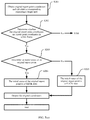
- FIG. 1 is a schematic diagram of a capacitance bright spot according to an embodiment of the present invention
- FIG. 2 is a flowchart of a control method according to an embodiment of the present invention.
- FIG. 3 is a schematic diagram of strength values of a capacitance bright spot according to an embodiment of the present invention.
- FIG. 4 is a schematic diagram of a capacitance signal change according to an embodiment of the present invention.
- FIG. 5( a ) , FIG. 5( b ) , and FIG. 5( c ) - 1 and FIG. 5( c ) - 2 are a flowchart of a control method according to an embodiment of the present invention
- FIG. 6( a ) - 1 and FIG. 6( a ) - 2 and FIG. 6( b ) - 1 and FIG. 6( b ) - 2 are a flowchart of another control method according to an embodiment of the present invention.
- FIG. 7 is a schematic structural diagram of a terminal according to an embodiment of the present invention.
- FIG. 8 is a schematic structural diagram of another terminal according to an embodiment of the present invention.
- Embodiments of the present invention provide a control method and a terminal.
- a capacitive touchscreen is disposed on the terminal.
- the terminal obtains a capacitance signal and report point coordinates, and determines, based on the capacitance signal and the report point coordinates, whether to suppress or flick a report point.
- an algorithm for suppressing report point flicking is set, and an algorithm for compensating report point coordinates after suppression on a report point stops is set, so that flicking caused by an unintentional operation performed by the user on the terminal operation screen is suppressed, and after suppression on the report point stops, a visual “jumping” effect that is of the report point and that is generated when the user performs the flick operation on the terminal screen is avoided.
- deviation compensation is performed on report point coordinates in each frame, so that a deviation caused by report point flicking suppression is completely compensated. In this way, when performing the flick operation, the user visually perceives that the report point moves smoothly, and therefore, user experience is improved.
- the report point is a point at which the user taps or presses the terminal screen when the user performs an operation on the terminal screen.
- the report point coordinates are position coordinates of the report point on the terminal screen.
- a reference point of the report point coordinates that is, an origin of coordinates (0, 0) may be customized.
- the terminal is a mobile phone, and the origin of coordinates may be set at an upper left corner, an upper right corner, or the like on a screen of the mobile phone.
- the capacitance signal is generated on the capacitive touchscreen.
- the capacitance signal is a matrix. As shown in FIG. 1 , each element in the matrix is corresponding to a rectangular area at a corresponding position on the capacitive touchscreen, and data on the element represents a strength value of the capacitance signal in the area. If the capacitance signal at a corresponding position that is on the capacitive touchscreen and that is touched by the user is relatively strong, a capacitance bright spot (as shown in FIG. 1 ) is generated. The capacitance bright spot is a nine-square grid, and the capacitance signal is relatively weak at another position.
- the capacitive touchscreen reports the capacitance signal of the entire capacitive touchscreen at a fixed frequency. Based on the capacitance signal, the terminal determines, through calculation, whether there is a need to report a point, and calculates a position, in other words, report point coordinates, of each report point.
- Strength values of the capacitance signal that are corresponding to all elements in the capacitance bright spot need to be obtained through calculation, and a maximum value of the capacitance signal in the capacitance bright spot, in other words, a strength value greater than strength values of the capacitance signal in eight adjacent squares, is obtained. Then, flooding is started from the maximum value.
- a fixed threshold is used for determining. When a strength value of the capacitance signal is greater than the fixed threshold, an element corresponding to the searched strength value of the capacitance signal is added to an area of a current capacitance bright spot. After the breadth-first search ends, a report point is matched with the capacitance bright spot. When a position of report point coordinates is included in the area of the capacitance bright spot, it is considered that the report point is a report point corresponding to the capacitance bright spot.
- a concept that is, a life cycle of a capacitance bright spot, further needs to be clearly understood.
- a continuous capacitance bright spot is generated on the terminal screen within a time period in which the user taps the terminal screen.
- a shape of the capacitance bright spot continuously changes with an area and a position of the finger touching the terminal screen.
- a time period from appearance to disappearance of the capacitance bright spot is referred to as one life cycle of the capacitance bright spot.
- a capacitance bright spot of one life cycle is corresponding to capacitance signals in several consecutive frames.
- the terminal has a function of managing a capacitance bright spot. After obtaining a capacitance bright spot in a current frame through calculation, the terminal determines, through a search, whether there is a capacitance bright spot that is in a previous frame and that is corresponding to the capacitance bright spot in the current frame. If there is the capacitance bright spot that is in the previous frame and that is corresponding to the capacitance bright spot in the current frame, the capacitance bright spot in the current frame is stored in a life cycle corresponding to the capacitance bright spot in the previous frame for management. If there is no capacitance bright spot that is in the previous frame and that is corresponding to the capacitance bright spot in the current frame, a new life cycle is established, and the capacitance bright spot in the current frame is stored in the newly established life cycle for management.
- a report point has two states: 1. a tapped (CLICK) state, indicating that the report point is a report point of a tap operation; and 2. a pressed (FLICK) state, indicating that the report point is a report point of a flick operation.
- a tapped (CLICK) state indicating that the report point is a report point of a tap operation
- a pressed (FLICK) state indicating that the report point is a report point of a flick operation.
- Different conditions are set for the terminal to determine whether the report point starts to flick, and how to compensate report point coordinates after the report point flicks.
- FIG. 2 is a flowchart of a control method according to an embodiment of the present invention. As shown in FIG. 2 , the method may include the following steps.
- the input information generated when a user performs an operation on a terminal screen is obtained, and the input information includes a capacitance signal and report point coordinates.
- the capacitance signal includes a strength value of a capacitance bright spot.
- the strength value of the capacitance bright spot is data corresponding to each element in the capacitance bright spot. As shown in FIG. 1 , each element is corresponding to a rectangular area at a corresponding position on the terminal screen.
- a terminal may determine a strength value of a capacitance bright spot in the capacitance signal in each frame. This may be briefly referred to as strength value determining. Based on the capacitance signal in each frame in the input information, the terminal may determine the strength value of the capacitance bright spot in the capacitance signal in each frame, and determine a maximum strength value of the capacitance bright spot in the capacitance signal in each frame. In this embodiment of the present invention, the maximum strength value of the capacitance bright spot may also be referred to as a maximum value “Peak” of the capacitance bright spot. As shown in FIG. 3 , the “Peak” is 3714. Based on maximum values of capacitance bright spots in two adjacent frames, a peak ratio “PeakRatio” is obtained through calculation.
- a capacitance signal in a current frame is a capacitance signal in an i th frame
- a capacitance signal in a previous frame is a capacitance signal in an (i ⁇ 1) th frame
- a capacitance signal in a next frame is a capacitance signal in an (i+1) th frame
- i is a positive integer greater than 1.
- a maximum value of a capacitance bright spot in the i th frame is Peak i
- a maximum value of a capacitance bright spot in the (i ⁇ 1) th frame is Peak i ⁇ 1 .
- PeakRatio i is a ratio of Peak i to Peak i ⁇ 1 , in other words,
- PeakRatio i Peak i Peak i - 1 .
- the terminal may calculate a maximum value in sums of strength values of the capacitance bright spot based on the strength values of the capacitance bright spot.
- a maximum value in sums of strength values of the capacitance bright spot in the i th frame is SquareSum i
- a maximum value in sums of strength values of the capacitance bright spot in the (i ⁇ 1) th frame is SquareSum i ⁇ 1
- the terminal may further determine SquareRatio i .
- SquareRatio i is a ratio of SquareSum i to SquareSum i ⁇ 1 , in other words,
- SquareSum i SquareSum i SquareSum i - 1 .
- the terminal may further use an ellipse to approximately simulate the capacitance bright spot generated when the user performs the operation on the terminal screen.
- the capacitance bright spot has a major axis and a minor axis.
- the major axis and the minor axis of the capacitance bright spot may change relatively greatly.
- the terminal determines a major axis value and a minor axis value of a capacitance bright spot in each frame based on the capacitance signal in each frame in the input information. In the i th frame, a major axis value is major i , and a minor axis value is minor i .
- a major axis value is major i ⁇ 1
- a minor axis value is minor i ⁇ 1
- An overall change of a major axis and a minor axis between the i th frame and the (i ⁇ 1) th frame is axisChange i .
- Displacement of an original report point between the i th frame and the (i ⁇ 1) th frame is dist i 0 .
- the original report point is position coordinates of the report point obtained through calculation by the terminal based on a touchscreen (touchscreen panel, TP) algorithm, namely, position coordinates on which report point coordinate compensation is not performed.
- TP touchscreen panel
- the terminal may further determine a flicking distance, and calculate a flicking distance move i 0 of a report point between the i th frame and a first frame.
- the displacement move i 0 is obtained by subtracting a flicking distance unnormalDist i unintentionally generated by the user between the i th frame and the first frame from a distance between the original report point coordinates in the i th frame and the original report point in the first frame.
- unnormalDist i is an accumulated value of all flicking distances unintentionally generated by the user from the first frame to the i th frame.
- the terminal may further use n1, n2, and eiff to describe a change of the capacitance bright spot between two frames during one-time interaction.
- n1 represents a capacitance signal change value in a movement direction of a gravity center of the capacitance bright spot
- n2 represents a capacitance signal change value in a direction opposite to the movement direction of the gravity center of the capacitance bright spot
- eiff represents an overall capacitance signal change value used between the two frames to complete gravity center displacement of one unit.
- the capacitance signal change values that are represented by n1, n2, and eiff are obtained from the strength values of the capacitance signal that are corresponding to all elements in the capacitance bright spot, namely, the strength values of the capacitance bright spot.
- n1 2408-1711
- n2 137-160.
- the gravity center of the capacitance bright spot is similar to a gravity center of an object.
- a center of the object is determined by a physical weight
- the gravity center of the capacitance bright spot is determined by a strength value of the capacitance bright spot.
- the gravity center of the capacitance bright spot meets the following formulas:
- x and y each represent a coordinate value of each element in each capacitance bright spot
- Capacity represents a strength value of the capacitance signal
- i represents the i th frame
- n represents an n th frame.
- n1, n2, and eiff may have the following cases: n1 is significantly greater than 0, n2 is significantly less than 0, and eiff is relatively small.
- n1, n2, and eiff may have the following values:
- Both n1 and n2 are greater than 0. In this case, it may be considered that strength of the capacitance signal obviously increases. Alternatively, both n1 and n2 are less than 0. In this case, it may be considered that strength of the capacitance signal obviously decreases.
- n1 is greater than 0, and n2 is less than 0.
- a difference between absolute values of n1 and n2 is relatively large due to an asymmetric change, and a value of eiff is relatively large.
- a capacitance bright spot S1 (x1, y1) changes to a capacitance bright spot S2 (x2, y2), and a center of gravity centers of the two capacitance bright spots are:
- n ⁇ 1 ⁇ ( x , y ) ⁇ C ⁇ ( ( x , y , S ⁇ ⁇ 2 ) - C ⁇ ( x , y , S ⁇ ⁇ 1 ) ) * 1 ⁇ ( ( x - X ) * d ⁇ x + ( y - Y ) * dy ⁇ 0 )
- ⁇ n ⁇ ⁇ 2 ⁇ ( x , y ) ⁇ C ⁇ ( ( x , y , S ⁇ ⁇ 2 ) - C ⁇ ( x , y , S ⁇ ⁇ 1 ) ) * 1 ⁇ ( ( x - X ) * d ⁇ x + ( y - Y ) * d ⁇ y ⁇ 0 )
- ⁇ ⁇ and eiff ⁇ n ⁇ ⁇ 1 + n ⁇ ⁇ 2 ⁇ d ⁇
- C(x, y, S1) and C(x, y, S2) each are equivalent to an f(x) function.
- the terminal may further obtain a ratio (Ratio).
- the ratio is a ratio of displacement of the gravity center of the capacitance bright spot to a movement distance of the gravity center in specific time period.
- a capacitance bright spot sequence that is formed in a process of interaction between the user and the terminal and that is continuous in a time period may be ⁇ S1, S2, S3, . . . , Si ⁇ .
- a length of the capacitance bright spot sequence has an upper limit, and an upper limit parameter may be set to WINDOW_SIZE.
- the ratio of the displacement of the gravity center to the movement distance of the gravity center may be calculated according to the following formula:
- the ratio is relatively small. In an active flicking process of the user, the ratio is close to 1.
- a limitation of a condition of n1, n2, and eiff is met, if the ratio is closer to 1, the user is more likely to actively or consciously perform a flick operation.
- the ratio is very small, an operation is determined as a flick operation only when the user consciously moves the gravity center for an enough long distance; otherwise, the terminal suppresses flicking.
- the finger of the user has different sizes in all directions
- unintentional flicking of the finger of the user has different distances in all the directions
- flicking lengths required in all the directions are also different.
- the terminal may perform ellipse fitting on a capacitance bright spot obtained based on a flooding algorithm, and calculate a length of a fitted ellipse in a direction according to a polar coordinate equation of the ellipse. Only when the displacement of the gravity center exceeds a specific proportion of a specific flicking length of the finger, an operation is determined as a flick operation, and a report point flicks.
- whether to use the report point coordinates in the previous frame as the report point coordinates in the current frame may be determined by determining the strength values of the capacitance bright spots that are in the capacitance signal in the current frame and the capacitance signal in the previous frame, by determining the major axis value and the minor axis value, or by determining the flicking distance.
- whether to suppress the report point may be determined in the following several manners.
- the terminal may use the report point coordinates in the previous frame as the report point coordinates in the current frame if it is determined that one or more of the peak ratio PeakRatio i , the maximum value SquareSum i in the sums of the strength values of the capacitance bright spot, and the maximum value Peak i of the capacitance bright spot meets/meet a preset condition.
- the terminal uses the report point coordinates in the previous frame as the report point coordinates in the current frame if it is determined that the peak ratio PeakRatio i , the maximum value SquareSum i in the sums of the strength values of the capacitance bright spot, the maximum value Peak i of the capacitance bright spot, and a report point status meet a preset condition.
- the maximum value of the capacitance bright spot is a maximum value in strength values corresponding to a plurality of elements in the capacitance bright spot.
- the peak ratio is a ratio of a maximum value of the capacitance bright spot in the current frame to a maximum value of the capacitance bright spot in the previous frame.
- the maximum value in the sums of the strength values of the capacitance bright spot is a maximum value in sums of data that is of four adjacent elements and that includes the maximum value in the strength values of the capacitance bright spot.
- the preset condition is as follows:
- PeakRatio i is less than a threshold
- SquareSum i is less than a threshold
- Peak i is less than a threshold
- PeakRatio i is less than a threshold
- SquareSum i is less than a threshold
- Peak i is less than a threshold
- the terminal may determine whether displacement from the report point coordinates in the previous frame to the report point coordinates in the current frame, and the major axis value and the minor axis value of the capacitance bright spot meet a preset condition, and use the report point coordinates in the previous frame as the report point coordinates in the current frame when the preset condition is met.
- the preset condition may be that, for example, when the displacement from the report point coordinates in the previous frame to the report point coordinates in the current frame is greater than a preset threshold dist i 0 , and an axis change value is greater than the preset threshold dist i 0 , the report point flicking is suppressed.
- the axis change value is the overall change axisChange i of the major axis and the minor axis. i represents the current frame, and i is a positive integer greater than 1.
- the terminal may alternatively determine the flicking distance move i 0 determine whether to suppress the report point flicking.
- the flicking distance may be a distance between the report point coordinates in the previous frame and the report point coordinates in the current frame, and when the flicking distance meets a preset condition, the report point coordinates in the previous frame are used as the report point coordinates in the current frame.
- the flicking distance move i 0 may alternatively be obtained by subtracting an unintentional flicking distance unnormalDist i from a distance between report point coordinates in the first frame and the report point coordinates in the current frame.
- the unintentional flicking distance unnormalDist i is a sum of all unintentional flicking distances from the first frame to the current frame.
- the report point flicking is controlled.
- the terminal may alternatively control the report point coordinates in the current frame to be the report point coordinates in the previous frame based on a first capacitance signal change value, a second capacitance signal change value, and a third signal change value.
- the first capacitance signal change value may be n1 in S 101
- the second capacitance signal change value may be n2 in S 101
- the third signal change value may be eiff in S 101 .
- n1 and n2 are both greater than 0, and are greater than thresholds respectively, the report point flicking is suppressed.
- n1 and n2 are both greater than 0, and are less than thresholds respectively, the report point flicking is suppressed.
- n1 is greater than 0, n2 is less than 0, and a value of eiff is relatively large, in other words, when n1 is greater than 0, n2 is less than 0, and the value of eiff is greater than a threshold, the report point flicking is suppressed.
- n1 and n2 are both very small, and the absolute values of n1 and n2 are each less than a threshold, or the absolute values of n1 and n2 are both less than a threshold, the report point flicking is suppressed.
- the threshold may be set based on a requirement, and a specific value is not limited in this embodiment of the present invention.
- whether to suppress the report point flicking may be further determined based on n1, n2, eiff, and the ratio (ratio).
- the ratio is the ratio of the displacement of the gravity center of the capacitance bright spot to the movement distance of the gravity center of the capacitance bright spot in the specific time period.
- the report point flicking is suppressed when two adjacent frames meet the following conditions:
- eiff is greater than a fixed threshold EIFF_TH
- n1 is greater than 0, n2 is less than 0, and the absolute values of n1 and n2 are both less than a preset threshold N_TH;
- a smaller ratio indicates a smaller ratio of the displacement from the report point coordinates in the previous frame to the report point coordinates in the current frame to the flicking length of the finger of the user on the terminal screen.
- the report point coordinates in the current frame change relative to the report point coordinates in the previous frame
- eiff is less than a fixed threshold EIFF_TH
- n1 is greater than 0, n2 is less than 0, and the absolute values of n1 and n2 are both greater than a preset threshold N_TH;
- a smaller ratio indicates a larger ratio of displacement from the report point coordinates in the current frame to a report point coordinates in the next frame to the flicking length of the finger of the user on the terminal screen.
- Ratio ⁇ 0.2, and the displacement of the report point between the current frame and the next frame is greater than a half of a length of the finger in a flicking direction.
- the terminal may alternatively determine, based on capacitance signals in two non-adjacent frames, whether to suppress or flick the report point.
- the terminal maintains a capacitance bright spot queue.
- the queue needs to satisfy that a change between capacitance bright spots in the first frame and the last frame is not significant.
- “not significant” means that absolute values of n1 and n2 between the two capacitance bright spots are less than a fixed threshold N_SIG_TH.
- a capacitive touchscreen of the terminal reports the capacitance signal of the entire terminal screen at a high frequency, and a change of a capacitance bright spot between frames is not very significant, it may be approximately considered that a change of a capacitance bright spot at the end of the queue relative to any capacitance bright spot in the queue is not very significant. If a new capacitance bright spot is added to the queue, a capacitance bright spot at the head of the queue leaves the queue until a change between a capacitance bright spot at the head of the queue and a capacitance bright spot at the end of the queue is not significant. If each capacitance bright spot leaving the queue and a capacitance bright spot currently at the end of the queue meet the following conditions, the report point flicks; otherwise, the report point flicking is suppressed. Possible conditions include:
- a change between each capacitance bright spot leaving the queue and the capacitance bright spot currently at the end of the queue is significant, that is, the absolute value of n1 is greater than or equal to N_SIG_TH, and the absolute value of n2 is greater than or equal to N_SIG_TH.
- the report point coordinates corresponding to the capacitance bright spot in the current frame change relative to the report point coordinates corresponding to the capacitance bright spot in the previous frame.
- n1 is greater than n2, n1 is greater than 0, n2 is less than 0, and the absolute value of n1 is greater than MULT_TH ⁇ the absolute value of n2.
- FIG. 5( a ) , FIG. 5( b ) , FIG. 5( c ) - 1 and FIG. 5( c ) - 2 , and FIG. 6 describes processes of the technical solutions of the embodiments of the present invention with reference to FIG. 5( a ) , FIG. 5( b ) , FIG. 5( c ) - 1 and FIG. 5( c ) - 2 , and FIG. 6 .
- FIG. 5( a ) , FIG. 5( b ) , and FIG. 5( c ) - 1 and FIG. 5( c ) - 2 are a flowchart of a method for determining whether a report point flicks according to an embodiment of the present invention.
- FIG. 6 is a flowchart of another method for determining whether a report point flicks according to an embodiment of the present invention.
- the method may include the following steps.
- the terminal obtains the original report point coordinates of an entered touch (touch) event.
- the original report point coordinates may be considered as report point coordinates in any frame in the report point coordinates in the plurality of frames.
- the capacitance bright spot is calculated based on the capacitance signals generated when the user performs the operation on the terminal screen.
- the report point coordinates in the first frame are generated at the very beginning of tapping the terminal screen in a process in which the user completes one-time interaction with the terminal screen, in other words, are report point coordinates of initially tapping the terminal screen.
- the terminal switches the status of the report point to a FLICK state.
- a final status of the report point of completing the one-time interaction is used as an initial status of a report point in next interaction.
- the FLICK state of the report point when the user lifts a finger from the terminal screen is used as the initial status of the report point in the next interaction.
- the terminal determines that the intentional flicking distance of the user is less than the preset threshold, the terminal switches the report point status to the CLICK state in a process in which the user lifts the finger from the terminal screen, and the CLICK state of the report point is used as the initial status of the report point in the next interaction.
- the status of the report point is switched at most once during the process in which the user completes the one-time interaction with the terminal screen.
- the terminal when determining that the original report point coordinates are the report point coordinates in the first frame, the terminal may directly output the original report point coordinates without switching the status of the report point.
- the initial status of the original report point has two types: 1. a CLICK state; and 2. a FLICK state.
- S 209 updating the report point status to the FLICK state.
- S 210 is performed: keeping the initial CLICK state of the report point.
- S 209 When the initial status of the original report point is the FLICK state, and the flicking distance meets the preset threshold, S 209 is performed: keeping the initial FLICK state of the report point.
- S 210 is performed: updating the initial status of the report point to the CLICK state.
- the flicking distance may be a flicking distance between the original report point and a report point in a previous frame, or may be a flicking distance between the original report point and a report point in a non-adjacent frame.
- the strength determining condition of the capacitance bright spot may be as follows:
- a peak ratio PeakRatio i is less than a threshold, and a maximum value SquareSum i in sums of strength values of the capacitance bright spot is less than a threshold, or a maximum value Peak i of the capacitance bright spot is less than a threshold.
- a peak ratio PeakRatio i is less than a threshold
- a maximum value SquareSum i in sums of strength values of the capacitance bright spot is less than a threshold
- a maximum value Peak i of the capacitance bright spot is less than a threshold
- the report point is in the CLICK state.
- the determining condition of the major axis and the minor axis may be as follows:
- Displacement from the report point coordinates in the previous frame to report point coordinates in a current frame is greater than a preset threshold dist i 0
- an axis change value is greater than the preset threshold dist i 0
- the axis change value is an overall change axisChange i of the major axis and the minor axis. i represents the current frame, and i is a positive integer greater than 1.
- the flicking determining condition is as follows:
- a flicking distance move i 0 is less than a threshold; or a flicking distance move i 0 is less than a threshold, and the report point is in the CLICK state.
- a definition of the flicking distance move i 0 is the same as that in S 101 or S 102 . For brevity, details are not described herein again.
- the terminal When the user performs a flick operation, the terminal cannot ensure that the terminal determines, at the beginning of flicking, that the flicking is a result of an intentional operation of the user. Therefore, the terminal may suppress report point flicking in first i frames after starting to report the report point, and stop suppressing after an i th frame. Therefore, to avoid a visual “jumping” effect of the report point that is brought to the user in a flicking process, the terminal may compensate and modify the original report point coordinates in several frames after the i th frame, instead of directly reporting the original report point coordinates of a system after the i th frame, until a deviation caused by suppressing the flicking is completely compensated.
- the report point coordinates may be compensated in the following manner.
- original report point coordinates in the i th frame are P i 0
- an original report point in an (i+1) th frame is P i+1 0
- compensated report point coordinates in the i th frame are P i c
- (dx, dy) is a value of a deviation of the original report point in the i th frame from an actual report point
- compensated report point coordinates in the (i+1) th frame are P i+1 c
- (dx ⁇ stepX, dy ⁇ stepY) is a value of a deviation of the original report point in the (i+1) th frame from an actual report point.
- stepX, stepY is used for compensation in each of several frames after the compensation starts, to completely compensate for the deviation generated by suppressing the flicking. After the compensation is completed, the compensated original report point coordinates are reported. In this way, the visual “jumping” effect caused by a change from report point flicking suppression to report point flicking is avoided.
- FIG. 6( a ) - 1 and FIG. 6( a ) - 2 and FIG. 6( b ) - 1 and FIG. 6( b ) - 2 are a flowchart of another method for determining whether a report point flicks according to an embodiment of the present invention. As shown in FIG. 6( a ) - 1 and FIG. 6( a ) - 2 , the method may include the following steps.
- the report point information includes report point coordinates and a report point index (pointIndex) of a report point in the current frame, and information about whether the report point coordinates need to be modified.
- pointIndex report point index
- processing methods in the x direction and the y direction are the same, but need to be separately performed, and are independent of each other.
- S 308 to S 314 in the x direction or S 308 to S 314 in the y direction may be first performed, or S 308 to S 314 in the x direction and S 308 to S 314 in the y direction are simultaneously performed.
- the offset is a compensated report point coordinates P i c in the current frame.
- the report point in the current frame is P i 0 , i represents the current frame, and i is a positive integer greater than 1.
- report point compensation refer to the following.
- S 316 is performed; or if the strength value of the capacitance bright spot is very small and is less than the preset threshold, S 322 is performed.
- a condition that the movement efficiency meets may be: eiff is less than a fixed threshold EIFF_TH.
- n1 and n2 are the same as those in S 101 or S 102 . For brief, details are not described herein again.
- a condition that n1 and n2 meet may be: n1 is greater than 0, n2 is less than 0, and absolute values of n1 and n2 are both greater than a preset threshold N_TH.
- the ratio is the same as the ratio Ratio defined in S 102 , and the ratio is a ratio of displacement from a gravity center of the capacitance bright spot in the current frame to a gravity center of a capacitance bright spot in the previous frame to a movement distance between the gravity center of the capacitance bright spot in the current frame and the gravity center of the capacitance bright spot in the previous frame.
- the preset condition may include:
- Dis2 may be in a unit of pixel.
- the foregoing three conditions each may be used as a condition for determining whether the ratio and Dis2 meet the preset condition.
- S 321 is performed.
- S 322 is performed.
- original report point coordinates in an i th frame are P i 0
- an original report point in an (i+1) th frame is P i+1 0
- compensated report point coordinates in the i th frame are P i c
- (dx, dy) is a value of a deviation of an original report point in the i th frame from an actual report point
- compensated report point coordinates in the (i+1) th frame are P i+1 c
- (dx ⁇ offsetRatio* ⁇ x, dy ⁇ offsetRatio* ⁇ y) is a value of a deviation of an original report point in the (i+1) th frame from an actual report point.
- offsetRatio* ⁇ x, offsetRatio* ⁇ y is used for compensation in each of several frames after the compensation starts, to completely compensate for the deviation generated by suppressing the flicking. After the compensation is completed, compensated original coordinates are reported. In this way, a visual “jumping” effect caused by a change from report point flicking suppression to report point flicking is avoided.
- FIG. 7 is a schematic structural diagram of a terminal according to an embodiment of the present invention.
- the terminal may include a processing unit 401 and a storage unit 402 .
- the storage unit 402 is configured to store a capacitance signal generated when a user performs an operation on a terminal screen.
- the processing unit 401 is configured to obtain input information, where the input information includes the capacitance signal and report point coordinates that are generated when the user performs the operation on the terminal screen.
- the processing unit 401 is further configured to: use report point coordinates in a previous frame as report point coordinates in a current frame if it is determined that a capacitance signal in the current frame and a capacitance signal in the previous frame that are in the input information meet a preset condition; or use report point coordinates in a previous frame as report point coordinates in a current frame if it is determined that the report point coordinates in the current frame and the report point coordinates in the previous frame that are in the input information meet a preset condition, to suppress flicking caused by an unintentional operation of the user. Therefore, user experience is improved.
- the capacitance signal includes a strength value of a capacitance bright spot
- the strength value of the capacitance bright spot is data corresponding to each element in the capacitance bright spot
- each element is corresponding to a rectangular area at a corresponding position on the terminal screen
- the processing unit 401 uses the report point coordinates in the previous frame as the report point coordinates in the current frame; or if it is determined that a peak ratio, a maximum value in sums of strength values of the capacitance bright spot, a maximum value of the capacitance bright spot, and a report point status meet a preset condition, the processing unit 401 uses the report point coordinates in the previous frame as the report point coordinates in the current frame.
- the maximum value of the capacitance bright spot is a maximum value in strength values corresponding to a plurality of elements in the capacitance bright spot.
- the peak ratio is a ratio of a maximum value of a capacitance bright spot in the current frame to a maximum value of a capacitance bright spot in the previous frame.
- the maximum value in the sums of the strength values of the capacitance bright spot is a maximum value in sums of data that is of four adjacent elements and that includes the maximum value in the strength values of the capacitance bright spot.
- the report point coordinates in the previous frame are used as the report point coordinates in the current frame.
- the capacitance signal further includes a major axis value and a minor axis value of a capacitance bright spot
- the processing unit 401 uses report point coordinates in a previous frame as report point coordinates in a current frame if it is determined that a capacitance signal in the current frame and a capacitance signal in the previous frame that are in the input information meet a preset condition includes:
- the processing unit 401 uses the report point coordinates in the previous frame as the report point coordinates in the current frame.
- the report point coordinates in the previous frame are used as the report point coordinates in the current frame.
- i represents the current frame, i is a positive integer greater than 1, and the axis change value meets the following formula:
- Axis ⁇ ⁇ change ⁇ ⁇ value ( Major ⁇ ⁇ axis ⁇ ⁇ value ⁇ ⁇ in ⁇ ⁇ a ⁇ ⁇ current ⁇ ⁇ frame - Major ⁇ ⁇ axis ⁇ ⁇ value ⁇ ⁇ in ⁇ ⁇ a ⁇ ⁇ previous ⁇ ⁇ frame ) 2 + ( Minor ⁇ ⁇ axis ⁇ ⁇ value ⁇ ⁇ in ⁇ ⁇ the ⁇ ⁇ current ⁇ ⁇ frame - Minor ⁇ ⁇ axis ⁇ ⁇ value ⁇ ⁇ in ⁇ ⁇ the ⁇ ⁇ previous ⁇ ⁇ frame ) 2 .
- the processing unit 401 is configured to use report point coordinates in a previous frame as report point coordinates in a current frame if it is determined that the report point coordinates in the current frame and report point coordinates in a first frame that are in the input information meet a preset condition includes:
- the processing unit 401 uses the report point coordinates in the previous frame as the report point coordinates in the current frame.
- the flicking distance is obtained by subtracting an unintentional flicking distance from a distance between the report point coordinates in the previous frame and the report point coordinates in the current frame, and the unintentional flicking distance is a sum of all unintentional flicking distances from the previous frame to the current frame.
- the report point coordinates in the previous frame are used as the report point coordinates in the current frame.
- that the processing unit 401 uses report point coordinates in a previous frame as report point coordinates in a current frame if it is determined that a capacitance signal in the current frame and a capacitance signal in the previous frame that are in the input information meet a preset condition includes:
- the processing unit 401 uses the report point coordinates in the previous frame as the report point coordinates in the current frame; or if it is determined that a first capacitance signal change value, a second capacitance signal change value, movement efficiency, and a ratio meet a preset condition, the processing unit 401 uses the report point coordinates in the previous frame as the report point coordinates in the current frame.
- the first capacitance signal change value is a change value of the capacitance signal in the current frame relative to the capacitance signal in the previous frame in a movement direction of a gravity center of a capacitance bright spot
- the second capacitance signal change value is a change value of the capacitance signal in the current frame relative to the capacitance signal in the previous frame in a direction opposite to the movement direction of the gravity center of the capacitance bright spot
- a third capacitance change value is an overall capacitance signal change value used for movement of the gravity center of the capacitance bright spot
- the ratio is a ratio of displacement of the gravity center of the capacitance bright spot to a movement distance of the gravity center of the capacitance bright spot in a specific time period.
- the processing unit 401 uses the report point coordinates in the previous frame as the report point coordinates in the current frame, and the preset condition may include:
- both of the first capacitance signal change value and the second capacitance signal change value are greater than zero, and the first capacitance signal change value and the second capacitance signal change value are greater than preset thresholds respectively; or both of the first capacitance signal change value and the second capacitance signal change value are less than zero, and the first capacitance signal change value and the second capacitance signal change value are less than preset thresholds respectively; or the first capacitance signal change value is greater than zero, the second capacitance signal change value is less than zero, and the movement efficiency is greater than a preset threshold; or both of an absolute value of the first capacitance signal change value and an absolute value of the second capacitance signal change value are less than a preset threshold.
- the processing unit 401 is further configured to: when it is determined that the report point coordinates in the current frame are not the report point coordinates in the previous frame, compensate the report point coordinates in the current frame and report point coordinates after the current frame.
- a visual “jumping” effect brought to the user after report point flicking stops is avoided by compensating the report point, so that user experience is improved.
- processing unit 401 compensates the report point coordinates in the current frame and report point coordinates after the current frame includes:
- the processing unit 401 compensates report point coordinates in each frame by using (stepX, stepY) or (offsetRatio x ⁇ x, offsetRatio x ⁇ y), where stepX and offsetRatio x ⁇ x each are a compensation amount of the coordinates in each frame in the x direction, and stepY and offsetRatio x ⁇ y each are a compensation amount in the y direction.
- stepX and offsetRatio x ⁇ x each are a compensation amount of the coordinates in each frame in the x direction
- stepY and offsetRatio x ⁇ y each are a compensation amount in the y direction.
- Functions of function units of the terminal may be implemented in the steps performed by the terminal in the embodiments shown in FIG. 2 , FIG. 5( a ) , FIG. 5( b ) , FIG. 5( c ) - 1 and FIG. 5( c ) - 2 , FIG. 6( a ) - 1 and FIG. 6( a ) - 2 , and FIG. 6( b ) - 1 and FIG. 6( b ) - 2 . Therefore, a specific working process of the terminal provided in this embodiment of the present invention is not described herein again.
- FIG. 8 is a schematic structural diagram of another terminal according to an embodiment of the present invention.
- the terminal may include a memory 501 , a processor 502 , and a computer program that is stored in the memory and that can be run on the processor.
- the processor executes the program, the following steps are implemented:
- the input information includes a capacitance signal and report point coordinates that are generated when a user performs an operation on a terminal screen;
- report point coordinates in a previous frame as report point coordinates in a current frame if it is determined that a capacitance signal in the current frame and a capacitance signal in the previous frame that are in the input information meet a preset condition; or using report point coordinates in a previous frame as report point coordinates in a current frame if it is determined that the report point coordinates in the current frame and the report point coordinates in the previous frame that are in the input information meet a preset condition, to suppress flicking caused by an unintentional operation of the user.
- the capacitance signal includes a strength value of a capacitance bright spot
- the strength value of the capacitance bright spot is data corresponding to each element in the capacitance bright spot
- each element is corresponding to a rectangular area at a corresponding position on the terminal screen
- the processor 502 uses the report point coordinates in the previous frame as the report point coordinates in the current frame; or if it is determined that a peak ratio, a maximum value in sums of strength values of the capacitance bright spot, a maximum value of the capacitance bright spot, and a report point status meet a preset condition, the processor 502 uses the report point coordinates in the previous frame as the report point coordinates in the current frame.
- the maximum value of the capacitance bright spot is a maximum value in strength values corresponding to a plurality of elements in the capacitance bright spot.
- the peak ratio is a ratio of a maximum value of a capacitance bright spot in the current frame to a maximum value of a capacitance bright spot in the previous frame.
- the maximum value in the sums of the strength values of the capacitance bright spot is a maximum value in sums of data that is of four adjacent elements and that includes the maximum value in the strength values of the capacitance bright spot.
- the report point coordinates in the previous frame are used as the report point coordinates in the current frame.
- the capacitance signal further includes a major axis value and a minor axis value of a capacitance bright spot
- the processor 502 uses report point coordinates in a previous frame as report point coordinates in a current frame if it is determined that a capacitance signal in the current frame and a capacitance signal in the previous frame that are in the input information meet a preset condition includes:
- the processor 502 uses the report point coordinates in the previous frame as the report point coordinates in the current frame.
- the report point coordinates in the previous frame are used as the report point coordinates in the current frame.
- i represents the current frame, i is a positive integer greater than 1, and the axis change value meets the following formula:
- Axis ⁇ ⁇ change ⁇ ⁇ value ( Major ⁇ ⁇ axis ⁇ ⁇ value ⁇ ⁇ in ⁇ ⁇ a ⁇ ⁇ current ⁇ ⁇ frame - Major ⁇ ⁇ axis ⁇ ⁇ value ⁇ ⁇ in ⁇ ⁇ a ⁇ ⁇ previous ⁇ ⁇ frame ) 2 + ( Minor ⁇ ⁇ axis ⁇ ⁇ value ⁇ ⁇ in ⁇ ⁇ the ⁇ ⁇ current ⁇ ⁇ frame - Minor ⁇ ⁇ axis ⁇ ⁇ value ⁇ ⁇ in ⁇ ⁇ the ⁇ ⁇ previous ⁇ ⁇ frame ) 2 .
- that the processor 502 is configured to use report point coordinates in a previous frame as report point coordinates in a current frame if it is determined that the report point coordinates in the current frame and report point coordinates in a first frame that are in the input information meet a preset condition includes:
- the processor 502 uses the report point coordinates in the previous frame as the report point coordinates in the current frame.
- the flicking distance is obtained by subtracting an unintentional flicking distance from a distance between the report point coordinates in the previous frame and the report point coordinates in the current frame, and the unintentional flicking distance is a sum of all unintentional flicking distances from the previous frame to the current frame.
- the report point coordinates in the previous frame are used as the report point coordinates in the current frame.
- that the processor 502 uses report point coordinates in a previous frame as report point coordinates in a current frame if it is determined that a capacitance signal in the current frame and a capacitance signal in the previous frame that are in the input information meet a preset condition includes:
- the processor 502 uses the report point coordinates in the previous frame as the report point coordinates in the current frame; or if it is determined that a first capacitance signal change value, a second capacitance signal change value, movement efficiency, and a ratio meet a preset condition, the processor 502 uses the report point coordinates in the previous frame as the report point coordinates in the current frame.
- the first capacitance signal change value is a change value of the capacitance signal in the current frame relative to the capacitance signal in the previous frame in a movement direction of a gravity center of a capacitance bright spot
- the second capacitance signal change value is a change value of the capacitance signal in the current frame relative to the capacitance signal in the previous frame in a direction opposite to the movement direction of the gravity center of the capacitance bright spot
- a third capacitance change value is an overall capacitance signal change value used for movement of the gravity center of the capacitance bright spot
- the ratio is a ratio of displacement of the gravity center of the capacitance bright spot to a movement distance of the gravity center of the capacitance bright spot in a specific time period.
- the processor 502 uses the report point coordinates in the previous frame as the report point coordinates in the current frame, and the preset condition includes:
- both of the first capacitance signal change value and the second capacitance signal change value are greater than zero, and the first capacitance signal change value and the second capacitance signal change value are greater than preset thresholds respectively; or both of the first capacitance signal change value and the second capacitance signal change value are less than zero, and the first capacitance signal change value and the second capacitance signal change value are less than preset thresholds respectively; or the first capacitance signal change value is greater than zero, the second capacitance signal change value is less than zero, and the movement efficiency is greater than a preset threshold; or both of an absolute value of the first capacitance signal change value and an absolute value of the second capacitance signal change value are less than a preset threshold.
- the processor 502 is further configured to: when it is determined that the report point coordinates in the current frame are not the report point coordinates in the previous frame, compensate the report point coordinates in the current frame and report point coordinates after the current frame. A visual “jumping” effect brought to the user after report point flicking stops is avoided by compensating the report point, so that user experience is improved.
- that the processor 502 compensates the report point coordinates in the current frame and report point coordinates after the current frame includes:
- the processor 502 compensates report point coordinates in each frame by using (stepX, stepY) or (offsetRatio x ⁇ x, offsetRatio x ⁇ y), where stepX and offsetRatio x ⁇ x each are a compensation amount of the coordinates in each frame in the x direction, and stepY and offsetRatio x ⁇ y each are a compensation amount in the y direction.
- stepX and offsetRatio x ⁇ x each are a compensation amount of the coordinates in each frame in the x direction
- stepY and offsetRatio x ⁇ y each are a compensation amount in the y direction.
- FIG. 2 For problem-resolving implementations of components of the terminal and beneficial effects in the foregoing embodiments, refer to the method implementations and beneficial effects shown in FIG. 2 , FIG. 5( a ) , FIG. 5( b ) , FIG. 5( c ) - 1 and FIG. 5( c ) - 2 , FIG. 6( a ) - 1 and FIG. 6( a ) - 2 , and FIG. 6( b ) - 1 and FIG. 6( b ) - 2 . Details are not described herein again.
- An embodiment of the present invention further provides a computer readable storage medium.
- the computer readable storage medium includes an instruction.
- the instruction When the instruction is run on a device, the device is enabled to perform the methods shown in FIG. 5( a ) , FIG. 5( b ) , FIG. 5( c ) - 1 and FIG. 5( c ) - 2 , FIG. 6( a ) - 1 and FIG. 6( a ) - 2 , and FIG. 6( b ) - 1 and FIG. 6( b ) - 2 .
- An embodiment of the present invention further provides a computer program product including an instruction.
- the instruction When the instruction is run on a computer, the computer is enabled to perform the methods shown in FIG. 5( a ) , FIG. 5( b ) , FIG. 5( c ) - 1 and FIG. 5( c ) - 2 , FIG. 6( a ) - 1 and FIG. 6( a ) - 2 , and FIG. 6( b ) - 1 and FIG. 6( b ) - 2 .
- All or some of the foregoing embodiments of the present invention may be implemented by software, hardware, firmware, or any combination thereof.
- all or some of the embodiments may be implemented in a form of a computer program product.
- the computer program product includes one or more computer instructions.
- the computer may be a general-purpose computer, a dedicated computer, a computer network, or another programmable apparatus.
- the computer instructions may be stored in a computer readable storage medium or may be transmitted from a computer readable medium to another computer readable medium.
- the computer instructions may be transmitted from a website, computer, server, or data center to another website, computer, server, or data center in a wired (for example, a coaxial cable, an optical fiber, or a digital subscriber line (digital subscriber line, DSL)) or wireless (for example, infrared, radio, or microwave) manner.
- the computer readable storage medium may be any usable medium accessible to a computer, or a data storage device, for example, a server or a data center, integrating one or more usable media.
- the usable medium may be a magnetic medium (for example, a floppy disk, a hard disk, or a magnetic tape), an optical medium (for example, a DVD), a semiconductor medium (for example, a solid-state drive), or the like.
Landscapes
- Engineering & Computer Science (AREA)
- General Engineering & Computer Science (AREA)
- Theoretical Computer Science (AREA)
- Human Computer Interaction (AREA)
- Physics & Mathematics (AREA)
- General Physics & Mathematics (AREA)
- User Interface Of Digital Computer (AREA)
- Position Input By Displaying (AREA)
Abstract
Description
axis Changei=√{square root over ((majori−majori−1)2+(min ori−min ori−1)2)}
disti 0=√{square root over ((x i 0 −x i−1 0)2+(y i 0 −y i−1 0)2)}
movei 0=√{square root over ((x i 0 −x 1 0)2+(y i 0 −y 1 0)2)}−unnormalDisti.
(dx,dy)=(
P i 0=(x i 0 ,y i 0),
P i+1 0=(x i+1 0 ,y i+1 0)=(x i 0 +Δx,y i 0 +Δy),
P i c=(x i c ,y i c)=(x i 0 −dx,y i 0 −dy), and
P i+1 c=(x i+1 c ,y i+1 c)=(x i 0 −dx+Δx+stepX,y i 0 −dyt+Δy+stepY).
P i 0=(x i 0 ,y i 0),
P i+1 0=(x i+1 0 ,y i+1 0)=(x i 0 +Δx,y i 0 +Δy),
P i c=(x i c ,y i c)=(x i 0 −dx,y i 0 −dy), and
P i+1 c=(x i+1 c ,y i+1 c)=(x i 0 −dx+Δx+offsetRatio*Δx,y i 0 −dy+Δy+offsetRatio*Δy).
Claims (18)
Applications Claiming Priority (5)
| Application Number | Priority Date | Filing Date | Title |
|---|---|---|---|
| CN201710954095.4 | 2017-10-13 | ||
| CN201710954095 | 2017-10-13 | ||
| CN201810037036.5A CN109669567B (en) | 2017-10-13 | 2018-01-15 | Control method and terminal |
| CN201810037036.5 | 2018-01-15 | ||
| PCT/CN2018/110185 WO2019072254A1 (en) | 2017-10-13 | 2018-10-15 | Control method and terminal |
Publications (2)
| Publication Number | Publication Date |
|---|---|
| US20200301560A1 US20200301560A1 (en) | 2020-09-24 |
| US11216116B2 true US11216116B2 (en) | 2022-01-04 |
Family
ID=66100414
Family Applications (1)
| Application Number | Title | Priority Date | Filing Date |
|---|---|---|---|
| US16/755,343 Active 2038-12-02 US11216116B2 (en) | 2017-10-13 | 2018-10-15 | Control method and terminal |
Country Status (2)
| Country | Link |
|---|---|
| US (1) | US11216116B2 (en) |
| WO (1) | WO2019072254A1 (en) |
Families Citing this family (1)
| Publication number | Priority date | Publication date | Assignee | Title |
|---|---|---|---|---|
| CN114968059B (en) * | 2021-05-13 | 2023-06-27 | 华为技术有限公司 | Control sliding method and electronic equipment |
Citations (14)
| Publication number | Priority date | Publication date | Assignee | Title |
|---|---|---|---|---|
| CN101930319A (en) | 2010-09-08 | 2010-12-29 | 敦泰科技有限公司 | Touch information reporting method of touch screen |
| US20110063214A1 (en) * | 2008-09-05 | 2011-03-17 | Knapp David J | Display and optical pointer systems and related methods |
| WO2014026568A1 (en) | 2012-08-15 | 2014-02-20 | 北京汇冠新技术股份有限公司 | Touch trace tracking method |
| US20140139495A1 (en) | 2012-11-19 | 2014-05-22 | Chunghwa Picture Tubes, Ltd. | System for optimizing touch tracks and method for optimizing touch tracks |
| CN103970322A (en) | 2013-01-30 | 2014-08-06 | 北京汇冠新技术股份有限公司 | Method and system for tracking handling of trajectory of touch screen |
| CN104834165A (en) | 2012-03-21 | 2015-08-12 | 海信集团有限公司 | Position determining method for laser spot on projection screen |
| CN105117020A (en) | 2015-09-23 | 2015-12-02 | 努比亚技术有限公司 | Edge interactive operation processing method and mobile terminal |
| CN105511776A (en) | 2015-11-24 | 2016-04-20 | 努比亚技术有限公司 | Mobile terminal and control method |
| US20160195998A1 (en) | 2014-08-18 | 2016-07-07 | Boe Technology Group Co., Ltd. | Touch positioning method for touch display device, and touch display device |
| WO2016119650A1 (en) | 2015-01-30 | 2016-08-04 | 努比亚技术有限公司 | Method and apparatus for preventing accidentally touching mobile terminal |
| CN106354333A (en) | 2016-09-30 | 2017-01-25 | 南京仁光电子科技有限公司 | Method for improving tracking accuracy of touch system |
| US20170090617A1 (en) | 2015-09-30 | 2017-03-30 | Lg Display Co., Ltd. | Multi-touch sensitive display device and method for assigning touch identification therein |
| US20180335921A1 (en) * | 2017-05-16 | 2018-11-22 | Apple Inc. | Devices, Methods, and Graphical User Interfaces For Navigating Between User Interfaces and Interacting with Control Objects |
| US10944945B2 (en) * | 2015-06-19 | 2021-03-09 | Sony Corporation | Projection device and projection method, projection module, electronic device, and program |
-
2018
- 2018-10-15 WO PCT/CN2018/110185 patent/WO2019072254A1/en unknown
- 2018-10-15 US US16/755,343 patent/US11216116B2/en active Active
Patent Citations (16)
| Publication number | Priority date | Publication date | Assignee | Title |
|---|---|---|---|---|
| US20110063214A1 (en) * | 2008-09-05 | 2011-03-17 | Knapp David J | Display and optical pointer systems and related methods |
| CN101930319A (en) | 2010-09-08 | 2010-12-29 | 敦泰科技有限公司 | Touch information reporting method of touch screen |
| CN104834165A (en) | 2012-03-21 | 2015-08-12 | 海信集团有限公司 | Position determining method for laser spot on projection screen |
| WO2014026568A1 (en) | 2012-08-15 | 2014-02-20 | 北京汇冠新技术股份有限公司 | Touch trace tracking method |
| US20140139495A1 (en) | 2012-11-19 | 2014-05-22 | Chunghwa Picture Tubes, Ltd. | System for optimizing touch tracks and method for optimizing touch tracks |
| CN103970322A (en) | 2013-01-30 | 2014-08-06 | 北京汇冠新技术股份有限公司 | Method and system for tracking handling of trajectory of touch screen |
| US20160195998A1 (en) | 2014-08-18 | 2016-07-07 | Boe Technology Group Co., Ltd. | Touch positioning method for touch display device, and touch display device |
| WO2016119650A1 (en) | 2015-01-30 | 2016-08-04 | 努比亚技术有限公司 | Method and apparatus for preventing accidentally touching mobile terminal |
| US20170357374A1 (en) * | 2015-01-30 | 2017-12-14 | Nubia Technology Co., Ltd | Method and apparatus for preventing accidental touch operation on mobile terminals |
| US10944945B2 (en) * | 2015-06-19 | 2021-03-09 | Sony Corporation | Projection device and projection method, projection module, electronic device, and program |
| CN105117020A (en) | 2015-09-23 | 2015-12-02 | 努比亚技术有限公司 | Edge interactive operation processing method and mobile terminal |
| US20170090617A1 (en) | 2015-09-30 | 2017-03-30 | Lg Display Co., Ltd. | Multi-touch sensitive display device and method for assigning touch identification therein |
| CN106557215A (en) | 2015-09-30 | 2017-04-05 | 乐金显示有限公司 | Multiple point touching induction display device and the method for specifying wherein touch identity |
| CN105511776A (en) | 2015-11-24 | 2016-04-20 | 努比亚技术有限公司 | Mobile terminal and control method |
| CN106354333A (en) | 2016-09-30 | 2017-01-25 | 南京仁光电子科技有限公司 | Method for improving tracking accuracy of touch system |
| US20180335921A1 (en) * | 2017-05-16 | 2018-11-22 | Apple Inc. | Devices, Methods, and Graphical User Interfaces For Navigating Between User Interfaces and Interacting with Control Objects |
Also Published As
| Publication number | Publication date |
|---|---|
| US20200301560A1 (en) | 2020-09-24 |
| WO2019072254A1 (en) | 2019-04-18 |
Similar Documents
| Publication | Publication Date | Title |
|---|---|---|
| KR101813061B1 (en) | Data reporting method and apparatus, and terminal device | |
| US9632680B2 (en) | Electronic device and method for controlling zooming of displayed object | |
| CN103135818B (en) | Quick operation response method and electronic equipment | |
| EP3678014B1 (en) | Control method and terminal | |
| CN102609136B (en) | Dynamic correcting method for reference value data, device and touch gesture identification method | |
| US11262876B2 (en) | Electronic device, touch detection circuit and update method for reference value of touch screen | |
| CN103309451B (en) | The display packing of mobile terminal and mobile terminal | |
| EP2851765B1 (en) | Method for reporting coordinate point of touch screen and mobile terminal | |
| US20150128095A1 (en) | Method, device and computer system for performing operations on objects in an object list | |
| EP3678001B1 (en) | Method and device for controlling output of report | |
| EP3101995A1 (en) | Terminal equipment processing method and terminal equipment | |
| CN113253878B (en) | Touch screen report point determining method and device, electronic equipment and storage medium | |
| CN104461256A (en) | Method and system for displaying interface elements | |
| CN103513820A (en) | Apparatus and method for controlling mode switch | |
| US11216116B2 (en) | Control method and terminal | |
| CN107168636A (en) | Gesture identification method, device, touch screen terminal and the storage medium of multiple point touching | |
| US20220335943A1 (en) | Human-computer interaction method, apparatus, and system | |
| CN105892842A (en) | Screen touch method and device | |
| CN108037889A (en) | Location regulation method, terminal and the computer-readable recording medium of virtual key | |
| US11656761B2 (en) | Touch hotspot adjustment method, apparatus, and device, and touchscreen terminal device | |
| CN104423826A (en) | Method and device for zooming by middle mouse button and scroll wheel | |
| CN104765561A (en) | Terminal | |
| KR20170059314A (en) | Input processing method and device | |
| CN105117151A (en) | Display interface operation method and terminal | |
| CN105404464B (en) | A kind of method and user terminal for controlling picture |
Legal Events
| Date | Code | Title | Description |
|---|---|---|---|
| FEPP | Fee payment procedure |
Free format text: ENTITY STATUS SET TO UNDISCOUNTED (ORIGINAL EVENT CODE: BIG.); ENTITY STATUS OF PATENT OWNER: LARGE ENTITY |
|
| STPP | Information on status: patent application and granting procedure in general |
Free format text: DOCKETED NEW CASE - READY FOR EXAMINATION |
|
| STPP | Information on status: patent application and granting procedure in general |
Free format text: RESPONSE TO NON-FINAL OFFICE ACTION ENTERED AND FORWARDED TO EXAMINER |
|
| STPP | Information on status: patent application and granting procedure in general |
Free format text: NOTICE OF ALLOWANCE MAILED -- APPLICATION RECEIVED IN OFFICE OF PUBLICATIONS |
|
| AS | Assignment |
Owner name: HUAWEI TECHNOLOGIES CO., LTD., CHINA Free format text: ASSIGNMENT OF ASSIGNORS INTEREST;ASSIGNORS:SHI, YUANCHUN;YU, CHUN;PAN, LIHANG;AND OTHERS;SIGNING DATES FROM 20200720 TO 20200727;REEL/FRAME:057422/0778 |
|
| STPP | Information on status: patent application and granting procedure in general |
Free format text: PUBLICATIONS -- ISSUE FEE PAYMENT VERIFIED |
|
| STCF | Information on status: patent grant |
Free format text: PATENTED CASE |
|
| CC | Certificate of correction |