US11215826B2 - Sealed edge lens for near eye display - Google Patents
Sealed edge lens for near eye display Download PDFInfo
- Publication number
- US11215826B2 US11215826B2 US15/201,352 US201615201352A US11215826B2 US 11215826 B2 US11215826 B2 US 11215826B2 US 201615201352 A US201615201352 A US 201615201352A US 11215826 B2 US11215826 B2 US 11215826B2
- Authority
- US
- United States
- Prior art keywords
- lens
- hoe
- layer
- edge
- sealant
- Prior art date
- Legal status (The legal status is an assumption and is not a legal conclusion. Google has not performed a legal analysis and makes no representation as to the accuracy of the status listed.)
- Active, expires
Links
- 239000000565 sealant Substances 0.000 claims abstract description 42
- 230000003287 optical effect Effects 0.000 claims abstract description 19
- 238000000034 method Methods 0.000 claims description 45
- 239000000463 material Substances 0.000 claims description 27
- 239000011521 glass Substances 0.000 claims description 13
- 238000004519 manufacturing process Methods 0.000 claims description 13
- 238000007493 shaping process Methods 0.000 claims description 13
- 229920000642 polymer Polymers 0.000 claims description 12
- 239000004820 Pressure-sensitive adhesive Substances 0.000 claims description 11
- 238000005520 cutting process Methods 0.000 claims description 7
- 238000000227 grinding Methods 0.000 claims description 7
- 238000005498 polishing Methods 0.000 claims description 6
- 238000005096 rolling process Methods 0.000 claims description 4
- 238000005266 casting Methods 0.000 claims description 3
- 238000007598 dipping method Methods 0.000 claims description 2
- 239000010410 layer Substances 0.000 description 65
- 210000001747 pupil Anatomy 0.000 description 22
- 238000003860 storage Methods 0.000 description 9
- 210000003128 head Anatomy 0.000 description 5
- 238000012545 processing Methods 0.000 description 4
- 238000010586 diagram Methods 0.000 description 3
- 230000032798 delamination Effects 0.000 description 2
- -1 for example Substances 0.000 description 2
- 238000012986 modification Methods 0.000 description 2
- 230000004048 modification Effects 0.000 description 2
- MDNWOSOZYLHTCG-UHFFFAOYSA-N Dichlorophen Chemical compound OC1=CC=C(Cl)C=C1CC1=CC(Cl)=CC=C1O MDNWOSOZYLHTCG-UHFFFAOYSA-N 0.000 description 1
- 238000010521 absorption reaction Methods 0.000 description 1
- 239000000443 aerosol Substances 0.000 description 1
- 230000004075 alteration Effects 0.000 description 1
- 238000004891 communication Methods 0.000 description 1
- 238000011109 contamination Methods 0.000 description 1
- 238000001816 cooling Methods 0.000 description 1
- 230000007123 defense Effects 0.000 description 1
- 238000013461 design Methods 0.000 description 1
- 238000005516 engineering process Methods 0.000 description 1
- 238000002347 injection Methods 0.000 description 1
- 239000007924 injection Substances 0.000 description 1
- 238000010030 laminating Methods 0.000 description 1
- 239000004973 liquid crystal related substance Substances 0.000 description 1
- 238000000465 moulding Methods 0.000 description 1
- 230000010287 polarization Effects 0.000 description 1
- 239000002861 polymer material Substances 0.000 description 1
- 229920002635 polyurethane Polymers 0.000 description 1
- 239000004814 polyurethane Substances 0.000 description 1
- 239000011253 protective coating Substances 0.000 description 1
- 239000011241 protective layer Substances 0.000 description 1
- 239000012812 sealant material Substances 0.000 description 1
- 239000004065 semiconductor Substances 0.000 description 1
- 239000007921 spray Substances 0.000 description 1
- 230000003068 static effect Effects 0.000 description 1
- 230000000007 visual effect Effects 0.000 description 1
Images


Classifications
-
- G—PHYSICS
- G02—OPTICS
- G02B—OPTICAL ELEMENTS, SYSTEMS OR APPARATUS
- G02B27/00—Optical systems or apparatus not provided for by any of the groups G02B1/00 - G02B26/00, G02B30/00
- G02B27/01—Head-up displays
- G02B27/017—Head mounted
- G02B27/0172—Head mounted characterised by optical features
-
- B—PERFORMING OPERATIONS; TRANSPORTING
- B29—WORKING OF PLASTICS; WORKING OF SUBSTANCES IN A PLASTIC STATE IN GENERAL
- B29D—PRODUCING PARTICULAR ARTICLES FROM PLASTICS OR FROM SUBSTANCES IN A PLASTIC STATE
- B29D11/00—Producing optical elements, e.g. lenses or prisms
- B29D11/00009—Production of simple or compound lenses
- B29D11/00403—Producing compound lenses
-
- B—PERFORMING OPERATIONS; TRANSPORTING
- B29—WORKING OF PLASTICS; WORKING OF SUBSTANCES IN A PLASTIC STATE IN GENERAL
- B29D—PRODUCING PARTICULAR ARTICLES FROM PLASTICS OR FROM SUBSTANCES IN A PLASTIC STATE
- B29D11/00—Producing optical elements, e.g. lenses or prisms
- B29D11/00009—Production of simple or compound lenses
- B29D11/00432—Auxiliary operations, e.g. machines for filling the moulds
- B29D11/00442—Curing the lens material
-
- B—PERFORMING OPERATIONS; TRANSPORTING
- B29—WORKING OF PLASTICS; WORKING OF SUBSTANCES IN A PLASTIC STATE IN GENERAL
- B29D—PRODUCING PARTICULAR ARTICLES FROM PLASTICS OR FROM SUBSTANCES IN A PLASTIC STATE
- B29D11/00—Producing optical elements, e.g. lenses or prisms
- B29D11/00932—Combined cutting and grinding thereof
-
- G—PHYSICS
- G02—OPTICS
- G02B—OPTICAL ELEMENTS, SYSTEMS OR APPARATUS
- G02B5/00—Optical elements other than lenses
- G02B5/32—Holograms used as optical elements
-
- H—ELECTRICITY
- H04—ELECTRIC COMMUNICATION TECHNIQUE
- H04N—PICTORIAL COMMUNICATION, e.g. TELEVISION
- H04N9/00—Details of colour television systems
- H04N9/12—Picture reproducers
- H04N9/31—Projection devices for colour picture display, e.g. using electronic spatial light modulators [ESLM]
- H04N9/3141—Constructional details thereof
-
- B—PERFORMING OPERATIONS; TRANSPORTING
- B29—WORKING OF PLASTICS; WORKING OF SUBSTANCES IN A PLASTIC STATE IN GENERAL
- B29K—INDEXING SCHEME ASSOCIATED WITH SUBCLASSES B29B, B29C OR B29D, RELATING TO MOULDING MATERIALS OR TO MATERIALS FOR MOULDS, REINFORCEMENTS, FILLERS OR PREFORMED PARTS, e.g. INSERTS
- B29K2075/00—Use of PU, i.e. polyureas or polyurethanes or derivatives thereof, as moulding material
-
- G—PHYSICS
- G02—OPTICS
- G02B—OPTICAL ELEMENTS, SYSTEMS OR APPARATUS
- G02B27/00—Optical systems or apparatus not provided for by any of the groups G02B1/00 - G02B26/00, G02B30/00
- G02B27/01—Head-up displays
- G02B27/0101—Head-up displays characterised by optical features
- G02B2027/014—Head-up displays characterised by optical features comprising information/image processing systems
-
- G—PHYSICS
- G02—OPTICS
- G02B—OPTICAL ELEMENTS, SYSTEMS OR APPARATUS
- G02B27/00—Optical systems or apparatus not provided for by any of the groups G02B1/00 - G02B26/00, G02B30/00
- G02B27/01—Head-up displays
- G02B27/017—Head mounted
- G02B27/0172—Head mounted characterised by optical features
- G02B2027/0174—Head mounted characterised by optical features holographic
-
- G—PHYSICS
- G02—OPTICS
- G02B—OPTICAL ELEMENTS, SYSTEMS OR APPARATUS
- G02B27/00—Optical systems or apparatus not provided for by any of the groups G02B1/00 - G02B26/00, G02B30/00
- G02B27/01—Head-up displays
- G02B27/017—Head mounted
- G02B2027/0178—Eyeglass type
Definitions
- Embodiments herein generally relate to head worn displays and heads up displays; and in particular to lenses for such displays.
- Modern display technology may be implemented to provide head worn displays (HWD) and to see through the display and to see information (e.g., images, text, or the like) in conjunction with the see through display.
- HWD head worn displays
- information e.g., images, text, or the like
- Such displays can be implemented in a variety of contexts, for example, defense, transportation, industrial, entertainment, wearable devices, or the like.
- an image may be reflected off a transparent projection surface to a user's eye to present an image in conjunction with a real world view.
- HWD systems have extremely difficult tradeoffs between various design and utility considerations, such as, for example, bulk, form-factor, see-through quality, field of view, etc. For example, achieving a normal eyewear form factor without bulk has not been achieved in a commercial head mounted display.
- FIG. 1 illustrates an example first system.
- FIG. 2 illustrates an example second system.
- FIG. 3 illustrates an example lens for a projection system.
- FIGS. 4A-4B illustrates example components for the lens of FIG. 3 .
- FIG. 5 illustrates an example mold for manufacturing the lens of FIG. 3 .
- FIG. 6 illustrate an example logic flow
- FIGS. 7A-7E illustrate an example first technique.
- FIGS. 8A-8E illustrate an example second technique.
- FIG. 9 illustrates an example computer readable medium.
- FIG. 10 illustrates a third example system.
- HWDs head worn displays
- HOEs holographic optical element
- the projection system and the lens can be mounted to a frame to be worn by a user, for example, glasses, a helmet, or the like.
- the projection system projects an image onto an inside (e.g., proximate to the user) surface of the lens.
- the HOE reflects the image to an exit pupil (or viewpoint).
- the exit pupil is proximate to one of the user's eyes, and specifically, to the pupil of the user's eye. As such, the user may perceive the reflected image.
- HWDs can be implemented to provide a projection system along with a lens that includes a holographic optical element (HOE).
- HOE holographic optical element
- the HOE is laminated onto an exterior surface of the lens.
- the HOE is laminated over an entire surface of the backside of the lens.
- a protective layer may be added on top of the HOE to protect the HOE.
- the edges of the HOE may be exposed resulting in delamination of the HOE and/or the protective coating from the lens.
- a lens could be formed by laminating an HOE between two lens blanks.
- a lens can be formed by injecting lens material into a mold, adding the HOE into the mold, and then injecting more lens material into the mold. Subsequently, the lenses can be shaped and sealant added to the lens edges to seal the joints between the layers and protect the HOE from contamination, delamination, or the like.
- variables such as, “a”, “b”, “c”, which are used to denote components where more than one component may be implemented. It is important to note, that there need not necessarily be multiple components and further, where multiple components are implemented, they need not be identical. Instead, use of variables to reference components in the figures is done for convenience and clarity of presentation.
- FIG. 1 illustrates an example of device 100 arranged according to the present disclosure. It is noted, that the device of this figure is depicted implemented as a pair of glasses. However, with some examples, the device 100 may be embodied as a pair of glasses (e.g., as depicted), as a pair of binoculars, a monocular device (e.g., scope, or the like), as goggles, as a helmet, as a visor, as a wearable device, or the like. Embodiments are not limited in this context.
- the device 100 is configured to provide a virtual display.
- the device 100 may provide a virtual display in conjunction with a real world view.
- the device 100 includes a glasses frame 101 and a projection system 110 mounted to the frame 101 .
- the device 100 includes a projection surface 300 , which may be a lens, such as, for example, a glasses lens as depicted.
- the projection surface 300 is referenced as lens 300 .
- embodiments are not limited in this context.
- the lens 300 can be removably mounted in the frame 101 .
- the lens 300 includes an HOE 310 (also referred to as a holographic optical combiner).
- the HOE 310 may be in a particular location and/or have particular optical characteristics to selectively reflect light incident on the lens 300 to an exit pupil (e.g., the exit pupil 237 shown in FIG. 2 ). It is important to note, the HOE 310 is depicted as covering only a portion of the viewable area of the lens 300 . However, in some examples, the HOE may cover substantially all, or all, of the viewable area of the lens 300 .
- the projection system 110 projects light onto the lens 300 .
- the projected light can correspond to virtual images.
- the lens 300 and specifically the HOE 310 , reflects (or redirects) the light towards a user's eye. More particularly the HOE 310 reflects the projected light (e.g., the projected image, or the like) to an exit pupil. This is described in greater detail with respect to FIG. 2 .
- the lens 300 and the HOE 310 redirect the projected images and also transmit light from the external environment to the user's eye. As such, a virtual image and a real world image may be presented to the user.
- the device 100 may include a projection system 110 and lens 300 including an HOE 310 for each eye. Examples are not limited in this context.
- the projection system 110 may comprise a light source, battery, and projector to project images onto the HOE 310 .
- the projection system 110 may comprise a scanning mirror to reflect and redirect light from the light source onto the HOE 310 .
- the scanning mirror may be a microelectromechanical system (MEMS) based scanning mirror.
- the projection system 110 may comprise a panel micro display (e.g., light emitting diode (LED) panel, liquid crystal display (LCD) panel, or the like).
- the projection system 110 may include control and graphics processing components configured to cause the system 110 to emit light from the light source and to scan and/or project the emitted light onto the lens 300 to project an image onto the HOE 310 .
- the lens 300 is described in greater detail below, for example, with respect to FIG. 2 and FIG. 3 . However, a general description of the lens 300 is given here.
- the lens 300 is an at least partially transparent surface with the HOE 310 disposed between layers of the lens 300 . More specifically, the lens 300 includes multiple layers with the HOE 310 sandwiched or placed between the layers.
- the lens 300 and the HOE 310 may transmit light incident on a real world side of the lens 300 to provide a real world view.
- the lens 300 is opaque and the lens 300 does not transmit light incident on a real world side of the lens 300 .
- the HOE 310 may have particular optical characteristics to reflect an image projected onto an internal surface of the lens 300 to an exit pupil in a particular location.
- the lens 300 may be sunglass lenses to reduce an amount or type of light transmitted through the lenses, for example, by polarization or absorption.
- the lenses 300 may be prescription lenses to correct or augment light perceived from the real world and/or the virtual image.
- FIG. 2 is a block diagram illustrating a side view of a system 200 including an example implementation of the device 100 .
- the exemplary implementation of the device 100 depicted in this figure is configured to project light to an exit pupil 237 (e.g., proximate to, or directed at, a user's eye, or the like). That is, the device 100 is configured to reflect the image projected onto an HOE 310 to a virtual aperture (e.g., the exit pupil 237 ) in the optical system.
- the system 200 includes the projection system 110 including a light source 105 to emit a light beam 231 of at least one wavelength. Alternatively, the system 110 may receive light emitted from a source not included in the system. Examples are not limited in this context.
- the light beam 231 is incident on (or received by) a scanning mirror 115 .
- the scanning mirror 115 rotates about a number of axes to scan the light beam 231 in angles 233 .
- the scanning mirror 115 scans the light beam 231 in angles 233 onto (or across) the lens 300 while the system 110 modulates or modifies the intensity of the scanned light beam 231 to correspond to a digital image.
- the scanning mirror 115 scans the light beam 231 over an area of lens 300 while the system 110 projects a digital image onto a portion of the area that includes the HOE 310 .
- the lens 300 comprises a first and a second lens half 320 and 330 .
- the lens halves 320 and 330 are referred to as lens blanks or lens portions. Disposed between the lens halves 320 and 330 is the HOE 310 . It is important to note, that the lens halves 320 and 330 may not necessarily correspond to an exact half portion of the lens 300 .
- the first lens blank can correspond to more than half of the total volume of the lens 300 while the second lens blank can correspond to less than half of the total volume of the lens 300 . Examples are not limited in this context.
- the lens halves 320 and/or 330 are referred to as a frontside lens portion or a backside lens portion. However, reference to frontside or backside is not intended to imply an orientation with respect to a user's eye, but merely to describe the relationship between each lens half and the HOE embedded between the lens halves.
- the lens 300 includes edge sealant 340 .
- edge sealant 340 In general, during manufacturing, once the HOE 310 is disposed between the lens halves 320 and 300 , the lens is shaped. The shaping process can include cutting, grinding, polishing, etc. Once the lens is shaped, sealant 340 can be applied to the lens edge. It is noted, that the sealant 340 is depicted of a size and shape to facilitate understanding. However, the size and shape of the sealant 340 may depend upon the sealant material, the application technique, the profile of the lens edge, or the like. Examples are not limited in this context.
- the HOE 310 is disposed between the lens halves 320 and 330 . It is noted, that a variety of styles of HOEs may be implemented as the HOE 310 . Furthermore, the HOE 310 may be manufactured by any of variety of manufacturing techniques, such as, for example, recording a hologram into a medium.
- the HOE 310 may be a combiner lens (e.g., a holographic optical combiner lens, or the like) that reflects light (e.g., off-angle light, or the like) incident on a first surface while transmitting light incident on a second opposite surface. Examples are not limited in this context.
- the lens 300 reflects the light 233 as diffracted light 235 to an exit pupil 237 .
- the lens 300 reflects and diffracts the light 233 to the entrance pupil 241 of a user's eye 240 .
- the lens 300 and particularly the HOE 310 , transmits light 239 , which is incident on a front side of the lens 300 and HOE 310 .
- the line of sight 243 of the eye e.g., corresponding to the eye pupil 241
- the user may perceive a virtual image (e.g., as projected to exit pupil 237 ) in conjunction with a real world view (e.g., corresponding to light 239 ).
- a single input pupil e.g., light beam 231
- a single exit pupil e.g., the exit pupil 237
- embodiments may be implemented to receive multiple input pupils and project an image with multiple exit pupils (e.g., based on a single input pupil or from multiple input pupils). Examples are not limited in this context.
- FIG. 3 illustrates the lens 300 , arranged according to at least one example of the present disclosure in greater detail.
- FIG. 3 depicts a cut-away side view of the lens 300 .
- the lens 300 includes a first lens portion 320 and a second lens portion 330 . Disposed between the portions 320 and 330 is the HOE 310 .
- Various techniques for manufacturing the lens 300 and particularly, placing the HOE 310 between the portions 320 and 330 are described below, for example, with respect to FIGS. 6-7 .
- the lens 300 includes a front side 301 and a backside 303 . It is noted, the front side 301 and the back side 303 is depicted for purposes of clarity only and not to be limiting.
- the front side 301 may be facing the environment while the backside 303 may be facing the user or viewer.
- the lens 300 includes an edge portion 305 .
- the edge portion 305 may be the face of the lens where the lens portions 320 and 330 as well as the HOE 310 are joined.
- the edge 305 of the lens 300 may be cut and/or ground to expose material of the lens portions 320 and 330 as well as the HOE 310 .
- This edge 305 of the lens 300 is covered with sealant 340 to protect the HOE 310 and the joints between the HOE 310 and the layers 320 and 330 .
- the lens 300 comprises portions 320 and 330 with HOE 310 disposed between the lens portions 320 and 330 .
- the lens portions 320 and 330 can be prefabricated and the lens 300 assembled from prefabricated components. In other examples, the lens portions 320 and 330 can be fabricated during assembly of the lens 300 .
- FIGS. 4A-4B depicts lens components 400 that can be provided to assemble lens 300 , according to at least one example of the present disclosure.
- FIG. 4A depicts the lens components from a side view while FIG. 4B depicts the lens components from a front view.
- lens component 400 can include a first lens blank 420 and a second lens blank 430 .
- the lens blanks 420 and 430 can be prefabricated from a material, such as, for example, glass, or the like.
- the lens blanks 420 and 430 can be provided along with the HOE 310 .
- the HOE 310 can be a thermoformed sheet of holographic optical material which is sized to be placed between lens blanks 420 and 430 .
- the HOE 310 can be affixed to the lens blank 420 , for example, via a pressure sensitive adhesive.
- the lens blank 430 can be affixed to the HOE, for example, via a pressure sensitive adhesive.
- the lens 300 can be shaped, for example, to have an eyewear lens shape, or another shape suitable for a near eye display.
- portions 401 of the lens can be removed.
- portions 401 can be removed via cutting, grinding, buffing, polishing, or the like.
- the removed portions may further expose the edge 305 where the joint between the HOE 310 and the layer (e.g., the layer 420 and 430 , or the like) is disposed.
- sealant e.g., sealant 340 , or the like
- sealant can be added to the edge to protect the HOE 310 and the joint between the HOE 310 and the layers.
- FIG. 5 depicts a mold 500 that can be used to form lens components during assembly of the lens 300 , according to at least one example of the present disclosure.
- the mold 500 includes a seam 501 between bottom mold portion 503 and top mold portion 505 .
- the top mold portion 505 includes a port 507 into which material can be injected (or cast, etc.) to form lens blanks 520 and 530 .
- first lens portion 520 can be formed by injecting a first amount of lens material (e.g., a polymer material, such as, for example, polyurethane, Trivex, or CR39, or the like) via the port 507 .
- the HOE 310 can then be placed into the mold.
- the mold can be opened at seam 501 , or the like.
- another amount of lens material can be injected into the mold via the port 507 to form the second lens portions 530 .
- the HOE can be disposed between lens portions 520 and 530 .
- multiple molds could be employed to form the lens 300 having lens portions 520 and 530 depicted in this figure.
- a first mold could be employed to form the first lens portion 520 and then the first lens portion 520 and the HOE 310 could be placed into a second mold to form the second lens portion 530 .
- the HOE 310 could be placed into a mold (e.g., mold 500 , or the like) and both lens portions 520 and 530 molded around HOE 310 , for example, in a single injection or casting process.
- FIG. 6 depicts a logic flow 600 for manufacturing a lens according to at least one example of the present disclosure.
- the logic flow 600 can be implemented to manufacture the lens 300 . It is noted, that the logic flow 600 could be implemented to form the lens 300 having lens portions 420 and 430 or 520 and 530 . Examples are not limited in this context.
- the logic flow 600 may begin at block 610 .
- At block 610 “provide a lens having a holographic optical element (HOE) disposed between first and second layers of the lens, the HOE exposed along an edge of the lens” the lens 300 can be provided.
- the HOE 310 disposed between lens portions 320 and 330 can be provided.
- HOE holographic optical element
- the lens 300 can be provided from prefabricated lens layers (e.g., the layers 420 and 430 , or the like) while in other examples, the lens 300 can be provided from manufacturing the layers using mold (e.g., the mold 500 , or the like).
- the lens can be shaped.
- the lens 300 can be shaped via cutting, grinding, or the like.
- material e.g., material 401 depicted in FIG. 4B , or the like
- a sealant to the edge of the lens to cover the HOE sealant can be applied to the lens to cover the edge where the joint between the HOE and the layers is.
- the lens 300 and particularly, the edge 305 of the lens 300 can be rolled on a wheel to apply sealant to the edge 305 .
- the edge 305 can be dipped into a sealant.
- the edge 305 can be coated via a spray or aerosol technique. Examples are not limited in this context.
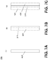
- FIGS. 7A-7E depict an example technique 700 to form a lens.
- the technique 700 can be implemented to from the lens 300 , for example, using lens components 400 . It is noted, the technique 700 is described with reference to the lens 300 and the components 400 for purposes of clarity of presentation and not to be limiting.
- the technique 700 can begin at block 710 .
- the lens layer 420 can be provided.
- the HOE 310 can be provided and affixed to the lens layer 420 .
- the HOE 310 can be affixed to the lens layer 420 via a pressure sensitive adhesive.
- the lens layer 430 can be provided and affixed to the HOE 310 .
- the lens layer 430 can be affixed to the HOE 310 via a pressure sensitive adhesive.
- the lens layers 420 and 430 and the HOE 310 can be shaped to lens shape 300 , or to an eyewear lens shape.
- the shape of the lens can have any shape suitable for the near eye display.
- the shape may conform to a shape to mount to a frame (e.g., glasses frame, or the like).
- more or less material e.g., material 401 , or the like
- the edge 305 of the lens 300 may be exposed.
- the joint between the HOE 310 and the layers 420 and 430 can be exposed.
- sealant 340 can be applied to the edge 305 to protect the HOE 310 .
- sealant 340 can be applied to cover and/or protect the joint between the HOE 310 and the layers 420 and 430 .
- sealant can be applied by rolling the edge 305 on a wheel to apply the sealant 340 to the edge 305 .
- FIGS. 8A-8E depict an example technique 800 to form a lens.
- the technique 700 can be implemented to from the lens 300 , for example, using mold 500 .
- the technique 800 is described with reference to the mold 500 and the lens layers 520 and 530 for purposes of clarity of presentation and not to be limiting.
- the technique 800 can begin at block 810 .
- the mold 500 can be filled with material to form the lens layer 520 .
- the mold 500 can be filled (e.g., via port 540 depicted in FIG. 5 , or the like) with a polymer and the polymer cured to form the lens layer 520 .
- FIG. 8A and block 810 the mold 500 can be filled with material to form the lens layer 520 .
- the mold 500 can be filled (e.g., via port 540 depicted in FIG. 5 , or the like) with a polymer and the polymer cured to form the lens layer 520 .
- the HOE 310 can be provided and affixed to the lens layer 520 .
- the mold 500 can be opened to expose the lens layer 520 and the HOE 310 can be affixed to the lens layer 520 via a pressure sensitive adhesive.
- the mold 500 can be filled with additional material to form the lens layer 530 .
- the mold 500 can be filled (e.g., via port 540 depicted in FIG. 5 , or the like) with a polymer and the polymer cured to form the lens layer 530 on the HOE 310 .
- molding can occur by pulling back one side of the mold so the cavity created by mold 500 may have the thickness of one of the mold halves (e.g., 520 , 530 , or the like). Subsequently, the HOE 310 can be applied and the cavities can accommodate both the HOE 310 and the second molded part.
- the mold halves e.g., 520 , 530 , or the like.
- the lens layers 520 and 530 and the HOE 310 can be shaped to lens shape 300 , or to an eyewear lens shape.
- the shape of the lens can have any shape suitable for the near eye display.
- the shape may conform to a shape to mount to a frame (e.g., glasses frame, or the like).
- more or less material e.g., material 401 , or the like
- the edge 305 of the lens 300 may be exposed.
- the joint between the HOE 310 and the layers 520 and 530 can be exposed.
- sealant 340 can be applied to the edge 305 to protect the HOE 310 .
- sealant 340 can be applied to cover and/or protect the joint between the HOE 310 and the layers 520 and 530 .
- sealant can be applied by rolling the edge 305 on a wheel to apply the sealant 340 to the edge 305 .
- FIG. 9 illustrates an embodiment of a storage medium 2000 .
- the storage medium 2000 may comprise an article of manufacture.
- the storage medium 2000 may include any non-transitory computer readable medium or machine readable medium, such as an optical, magnetic or semiconductor storage.
- the storage medium 2000 may store various types of computer executable instructions e.g., 2002 ).
- the storage medium 2000 may store various types of computer executable instructions to implement technique 600 .
- the storage medium 2000 may store various types of computer executable instructions to implement technique 700 .
- the storage medium 2000 may store various types of computer executable instructions to implement technique 800 .
- Examples of a computer readable or machine readable storage medium may include any tangible media capable of storing electronic data, including volatile memory or non-volatile memory, removable or non-removable memory, erasable or non-erasable memory, writeable or re-writeable memory, and so forth.
- Examples of computer executable instructions may include any suitable type of code, such as source code, compiled code, interpreted code, executable code, static code, dynamic code, object-oriented code, visual code, and the like. The examples are not limited in this context.
- FIG. 10 is a diagram of an exemplary system embodiment and in particular, depicts a platform 3000 , which may include various elements.
- platform (system) 3000 may include a processor/graphics core 3002 , a chipset/platform control hub (PCH) 3004 , an input/output (I/O) device 3006 , a random access memory (RAM) (such as dynamic RAM (DRAM)) 3008 , and a read only memory (ROM) 3010 , display electronics 3020 (e.g., lens 300 , or the like), projector 3022 (e.g., projector 110 , or the like), and various other platform components 3014 (e.g., a fan, a cross flow blower, a heat sink, DTM system, cooling system, housing, vents, and so forth).
- System 3000 may also include wireless communications chip 3016 and graphics device 3018 . The embodiments, however, are not limited to these elements.
- I/O device 3006 , RAM 3008 , and ROM 3010 are coupled to processor 3002 by way of chipset 3004 .
- Chipset 3004 may be coupled to processor 3002 by a bus 3012 .
- bus 3012 may include multiple lines.
- Processor 3002 may be a central processing unit comprising one or more processor cores and may include any number of processors having any number of processor cores.
- the processor 3002 may include any type of processing unit, such as, for example, CPU, multi-processing unit, a reduced instruction set computer (RISC), a processor that have a pipeline, a complex instruction set computer (CISC), digital signal processor (DSP), and so forth.
- processor 3002 may be multiple separate processors located on separate integrated circuit chips.
- processor 3002 may be a processor having integrated graphics, while in other embodiments processor 3002 may be a graphics core or cores.
- Some embodiments may be described using the expression “one embodiment” or “an embodiment” along with their derivatives. These terms mean that a particular feature, structure, or characteristic described in connection with the embodiment is included in at least one embodiment. The appearances of the phrase “in one embodiment” in various places in the specification are not necessarily all referring to the same embodiment. Further, some embodiments may be described using the expression “coupled” and “connected” along with their derivatives. These terms are not necessarily intended as synonyms for each other. For example, some embodiments may be described using the terms “connected” and/or “coupled” to indicate that two or more elements are in direct physical or electrical contact with each other. The term “coupled,” however, may also mean that two or more elements are not in direct contact with each other, but yet still co-operate or interact with each other. Furthermore, aspects or elements from different embodiments may be combined.
- the disclosure can be implemented in a variety of embodiments.
- the disclosure can be implemented in the non-exhaustive listing of example embodiments given below.
- a method to manufacture a wearable display lens comprising: providing a lens having a holographic optical element (HOE) disposed between a first layer and a second layer of the lens, the HOE exposed along an edge of the lens; shaping the lens; and applying a sealant to the edge of the lens to cover the HOE.
- HOE holographic optical element
- shaping the lens comprising at least one of cutting the lens, grinding the lens, or polishing the lens.
- shaping the lens comprising at least one of cutting the edge of the lens, grinding the edge of the lens, or polishing the edge of the lens.
- providing the lens comprising: providing the first layer and the second layer; applying the HOE to a back surface of the first layer; and applying the second layer to the HOE to place the HOE between the first and the second layer.
- providing the lens comprising: providing the first layer; applying the HOE to a back surface of the first layer; placing the first layer and the HOE into a mold; and filling the mold with a lens material to form the second layer the HOE.
- the method of example 8 providing the first layer comprising filling the mold with the lens material to form the first layer.
- a projection system lens comprising: a first lens layer; a holographic optical element (HOE) affixed to a back surface of the first lens layer; a second lens layer affixed to the HOE; and a sealant disposed on an edge of the lens, wherein joints between the first layer and the HOE and the second layer and the HOE are on the edge, the sealant to cover the joints.
- HOE holographic optical element
- a system for projecting an image comprising: a frame; a lens coupled to the frame, the lens comprising a holographic optical element (HOE) disposed between a first lens layer and a second lens layer and a sealant disposed on an edge of the lens, wherein joints between the first lens layer and the HOE and the second lens layer and the HOE are on the edge; and a projector coupled to the frame, the projector to project light onto the HOE.
- HOE holographic optical element
- any one of examples 20 to 26, comprising a graphic processor to receive an image information element to include an indication of an image and the send a display control signal to the projector to cause the projector to project one or more pixels corresponding to the image onto the HOE.
Landscapes
- Engineering & Computer Science (AREA)
- Physics & Mathematics (AREA)
- Health & Medical Sciences (AREA)
- Manufacturing & Machinery (AREA)
- Ophthalmology & Optometry (AREA)
- Mechanical Engineering (AREA)
- General Physics & Mathematics (AREA)
- Optics & Photonics (AREA)
- Multimedia (AREA)
- Signal Processing (AREA)
Abstract
Description
Claims (24)
Priority Applications (1)
| Application Number | Priority Date | Filing Date | Title |
|---|---|---|---|
| US15/201,352 US11215826B2 (en) | 2016-07-01 | 2016-07-01 | Sealed edge lens for near eye display |
Applications Claiming Priority (1)
| Application Number | Priority Date | Filing Date | Title |
|---|---|---|---|
| US15/201,352 US11215826B2 (en) | 2016-07-01 | 2016-07-01 | Sealed edge lens for near eye display |
Publications (2)
| Publication Number | Publication Date |
|---|---|
| US20180003976A1 US20180003976A1 (en) | 2018-01-04 |
| US11215826B2 true US11215826B2 (en) | 2022-01-04 |
Family
ID=60807320
Family Applications (1)
| Application Number | Title | Priority Date | Filing Date |
|---|---|---|---|
| US15/201,352 Active 2038-07-25 US11215826B2 (en) | 2016-07-01 | 2016-07-01 | Sealed edge lens for near eye display |
Country Status (1)
| Country | Link |
|---|---|
| US (1) | US11215826B2 (en) |
Families Citing this family (2)
| Publication number | Priority date | Publication date | Assignee | Title |
|---|---|---|---|---|
| US10437071B2 (en) * | 2015-10-12 | 2019-10-08 | North Inc. | Adjustable pupil distance wearable display |
| US10409076B2 (en) * | 2015-10-12 | 2019-09-10 | North Inc. | Adjustable pupil distance wearable display |
Citations (2)
| Publication number | Priority date | Publication date | Assignee | Title |
|---|---|---|---|---|
| US20060192306A1 (en) * | 2005-02-25 | 2006-08-31 | The Microoptical Corporation | Manufacturing methods for embedded optical system |
| US20160033771A1 (en) * | 2013-03-25 | 2016-02-04 | Ecole Polytechnique Federale De Lausanne | Method and apparatus for head worn display with multiple exit pupils |
-
2016
- 2016-07-01 US US15/201,352 patent/US11215826B2/en active Active
Patent Citations (2)
| Publication number | Priority date | Publication date | Assignee | Title |
|---|---|---|---|---|
| US20060192306A1 (en) * | 2005-02-25 | 2006-08-31 | The Microoptical Corporation | Manufacturing methods for embedded optical system |
| US20160033771A1 (en) * | 2013-03-25 | 2016-02-04 | Ecole Polytechnique Federale De Lausanne | Method and apparatus for head worn display with multiple exit pupils |
Also Published As
| Publication number | Publication date |
|---|---|
| US20180003976A1 (en) | 2018-01-04 |
Similar Documents
| Publication | Publication Date | Title |
|---|---|---|
| US11543661B2 (en) | Compact head-mounted display system protected by a hyperfine structure | |
| US9568734B1 (en) | Lens with lightguide insert for head wearable display | |
| US10437071B2 (en) | Adjustable pupil distance wearable display | |
| US9366869B2 (en) | Thin curved eyepiece for see-through head wearable display | |
| US10642042B2 (en) | Lens and embedded optical element for near eye display | |
| KR102642848B1 (en) | Wearable optical display system for unobstructed vision | |
| JP2022109269A (en) | Spectacle lens for optical image pickup device and augmented reality spectacles | |
| US10409076B2 (en) | Adjustable pupil distance wearable display | |
| US10133071B2 (en) | Replaceable optical element for near eye display | |
| KR20180081043A (en) | System, article and method for integrating spectacle lens and hologram optical element | |
| US20140327603A1 (en) | Virtual image display apparatus | |
| CN110568616B (en) | Method for providing a head-mounted optical system | |
| US20200041790A1 (en) | Catadioptric freeform head mounted display | |
| US10788670B2 (en) | Method to manufacture lens having embedded holographic optical element for near eye display | |
| CN110389446A (en) | Augmented reality shows device and method | |
| JP6307857B2 (en) | Virtual image display device | |
| US11215826B2 (en) | Sealed edge lens for near eye display | |
| US20230405949A1 (en) | Optical system and method for manufacturing an optical system |
Legal Events
| Date | Code | Title | Description |
|---|---|---|---|
| AS | Assignment |
Owner name: INTEL CORPORATION, CALIFORNIA Free format text: ASSIGNMENT OF ASSIGNORS INTEREST;ASSIGNORS:WADE, ANDREW G.;DAWN, ANDREW;GROFF, JOHN;AND OTHERS;SIGNING DATES FROM 20161114 TO 20161130;REEL/FRAME:040608/0360 |
|
| STCV | Information on status: appeal procedure |
Free format text: APPEAL BRIEF (OR SUPPLEMENTAL BRIEF) ENTERED AND FORWARDED TO EXAMINER |
|
| STCV | Information on status: appeal procedure |
Free format text: EXAMINER'S ANSWER TO APPEAL BRIEF MAILED |
|
| STCV | Information on status: appeal procedure |
Free format text: ON APPEAL -- AWAITING DECISION BY THE BOARD OF APPEALS |
|
| STCV | Information on status: appeal procedure |
Free format text: BOARD OF APPEALS DECISION RENDERED |
|
| STPP | Information on status: patent application and granting procedure in general |
Free format text: DOCKETED NEW CASE - READY FOR EXAMINATION |
|
| FEPP | Fee payment procedure |
Free format text: PETITION RELATED TO MAINTENANCE FEES GRANTED (ORIGINAL EVENT CODE: PTGR); ENTITY STATUS OF PATENT OWNER: LARGE ENTITY |
|
| STPP | Information on status: patent application and granting procedure in general |
Free format text: NOTICE OF ALLOWANCE MAILED -- APPLICATION RECEIVED IN OFFICE OF PUBLICATIONS |
|
| STPP | Information on status: patent application and granting procedure in general |
Free format text: PUBLICATIONS -- ISSUE FEE PAYMENT VERIFIED |
|
| STCF | Information on status: patent grant |
Free format text: PATENTED CASE |
|
| AS | Assignment |
Owner name: COVESTRO DEUTSCHLAND AG, GERMANY Free format text: ASSIGNMENT OF ASSIGNORS INTEREST;ASSIGNOR:INTEL CORPORATION;REEL/FRAME:058885/0025 Effective date: 20211215 |