US11215519B2 - Device component swelling detection - Google Patents

Device component swelling detection Download PDF

Info

Publication number
US11215519B2
US11215519B2 US16/795,956 US202016795956A US11215519B2 US 11215519 B2 US11215519 B2 US 11215519B2 US 202016795956 A US202016795956 A US 202016795956A US 11215519 B2 US11215519 B2 US 11215519B2
Authority
US
United States
Prior art keywords
component
gap
electronic device
pressure sensor
adaptive
Prior art date
Legal status (The legal status is an assumption and is not a legal conclusion. Google has not performed a legal analysis and makes no representation as to the accuracy of the status listed.)
Active
Application number
US16/795,956
Other versions
US20210262883A1 (en
Inventor
Bouziane Yebka
Tin-Lup Wong
Philip John Jakes
Current Assignee (The listed assignees may be inaccurate. Google has not performed a legal analysis and makes no representation or warranty as to the accuracy of the list.)
Lenovo Singapore Pte Ltd
Original Assignee
Lenovo Singapore Pte Ltd
Priority date (The priority date is an assumption and is not a legal conclusion. Google has not performed a legal analysis and makes no representation as to the accuracy of the date listed.)
Filing date
Publication date
Application filed by Lenovo Singapore Pte Ltd filed Critical Lenovo Singapore Pte Ltd
Priority to US16/795,956 priority Critical patent/US11215519B2/en
Assigned to LENOVO (SINGAPORE) PTE. LTD. reassignment LENOVO (SINGAPORE) PTE. LTD. ASSIGNMENT OF ASSIGNORS INTEREST (SEE DOCUMENT FOR DETAILS). Assignors: JAKES, PHILIP JOHN, WONG, TIN-LUP, YEBKA, BOUZIANE
Publication of US20210262883A1 publication Critical patent/US20210262883A1/en
Application granted granted Critical
Publication of US11215519B2 publication Critical patent/US11215519B2/en
Active legal-status Critical Current
Anticipated expiration legal-status Critical

Links

Images

Classifications

    • GPHYSICS
    • G01MEASURING; TESTING
    • G01LMEASURING FORCE, STRESS, TORQUE, WORK, MECHANICAL POWER, MECHANICAL EFFICIENCY, OR FLUID PRESSURE
    • G01L9/00Measuring steady of quasi-steady pressure of fluid or fluent solid material by electric or magnetic pressure-sensitive elements; Transmitting or indicating the displacement of mechanical pressure-sensitive elements, used to measure the steady or quasi-steady pressure of a fluid or fluent solid material, by electric or magnetic means
    • G01L9/0041Transmitting or indicating the displacement of flexible diaphragms
    • G01L9/0051Transmitting or indicating the displacement of flexible diaphragms using variations in ohmic resistance
    • G01L9/0052Transmitting or indicating the displacement of flexible diaphragms using variations in ohmic resistance of piezoresistive elements
    • G01L9/0055Transmitting or indicating the displacement of flexible diaphragms using variations in ohmic resistance of piezoresistive elements bonded on a diaphragm
    • GPHYSICS
    • G01MEASURING; TESTING
    • G01LMEASURING FORCE, STRESS, TORQUE, WORK, MECHANICAL POWER, MECHANICAL EFFICIENCY, OR FLUID PRESSURE
    • G01L1/00Measuring force or stress, in general
    • G01L1/26Auxiliary measures taken, or devices used, in connection with the measurement of force, e.g. for preventing influence of transverse components of force, for preventing overload
    • GPHYSICS
    • G01MEASURING; TESTING
    • G01MTESTING STATIC OR DYNAMIC BALANCE OF MACHINES OR STRUCTURES; TESTING OF STRUCTURES OR APPARATUS, NOT OTHERWISE PROVIDED FOR
    • G01M3/00Investigating fluid-tightness of structures
    • G01M3/02Investigating fluid-tightness of structures by using fluid or vacuum
    • G01M3/04Investigating fluid-tightness of structures by using fluid or vacuum by detecting the presence of fluid at the leakage point
    • G01M3/16Investigating fluid-tightness of structures by using fluid or vacuum by detecting the presence of fluid at the leakage point using electric detection means
    • G01M3/18Investigating fluid-tightness of structures by using fluid or vacuum by detecting the presence of fluid at the leakage point using electric detection means for pipes, cables or tubes; for pipe joints or seals; for valves; for welds; for containers, e.g. radiators
    • G01M3/186Investigating fluid-tightness of structures by using fluid or vacuum by detecting the presence of fluid at the leakage point using electric detection means for pipes, cables or tubes; for pipe joints or seals; for valves; for welds; for containers, e.g. radiators for containers, e.g. radiators
    • HELECTRICITY
    • H01ELECTRIC ELEMENTS
    • H01MPROCESSES OR MEANS, e.g. BATTERIES, FOR THE DIRECT CONVERSION OF CHEMICAL ENERGY INTO ELECTRICAL ENERGY
    • H01M10/00Secondary cells; Manufacture thereof
    • H01M10/42Methods or arrangements for servicing or maintenance of secondary cells or secondary half-cells
    • H01M10/48Accumulators combined with arrangements for measuring, testing or indicating the condition of cells, e.g. the level or density of the electrolyte
    • H01M10/482Accumulators combined with arrangements for measuring, testing or indicating the condition of cells, e.g. the level or density of the electrolyte for several batteries or cells simultaneously or sequentially
    • HELECTRICITY
    • H01ELECTRIC ELEMENTS
    • H01MPROCESSES OR MEANS, e.g. BATTERIES, FOR THE DIRECT CONVERSION OF CHEMICAL ENERGY INTO ELECTRICAL ENERGY
    • H01M2200/00Safety devices for primary or secondary batteries
    • H01M2200/20Pressure-sensitive devices
    • YGENERAL TAGGING OF NEW TECHNOLOGICAL DEVELOPMENTS; GENERAL TAGGING OF CROSS-SECTIONAL TECHNOLOGIES SPANNING OVER SEVERAL SECTIONS OF THE IPC; TECHNICAL SUBJECTS COVERED BY FORMER USPC CROSS-REFERENCE ART COLLECTIONS [XRACs] AND DIGESTS
    • Y02TECHNOLOGIES OR APPLICATIONS FOR MITIGATION OR ADAPTATION AGAINST CLIMATE CHANGE
    • Y02EREDUCTION OF GREENHOUSE GAS [GHG] EMISSIONS, RELATED TO ENERGY GENERATION, TRANSMISSION OR DISTRIBUTION
    • Y02E60/00Enabling technologies; Technologies with a potential or indirect contribution to GHG emissions mitigation
    • Y02E60/10Energy storage using batteries

Definitions

  • Mobile electronic devices for examples smart phones, tablets, laptop computers, and the like, must be powered in some way.
  • the device In situations where the device is not attached to a connected power source such as an AC line, a charger, a power bank, etc., the device must draw energy from one or more battery packs integrated into the device. Through battery discharge, the device may draw the energy needed from the battery pack to power the device and/or to operate one or more applications on the device.
  • one aspect provides an electronic device, comprising: a device component; a pressure sensor integrated into a surface lining of the device component; and at least one adaptive gap-filling component situated between the surface lining of the device component and a wall of the electronic device that at least partially surrounds the device component.
  • Another aspect provides a method, comprising: detecting, using a pressure sensor integrated into a surface lining of a device component housed within an electronic device, a swelling event associated with the device component; wherein the detecting comprises utilizing at least one adaptive gap-filling component, wherein the at least one gap-filling component is situated between the surface lining of the device component and a wall of the electronic device that at least partially surrounds the device component.
  • a further aspect provides a method, comprising: auto-zeroing a pressure sensor integrated into a surface lining of a device component housed within an electronic device, wherein the auto-zeroing comprises: introducing at least one adaptive gap-filling component between the surface lining of the device component and a wall of the electronic device that at least partially surrounds the device component.
  • FIG. 1 (A-B) illustrates a prior art configuration of a device component having a pressure sensor.
  • FIG. 2 provides a graph of actual device component swelling versus detected device component swelling.
  • FIG. 3 (A-B) provides an example representation of a gap-filling component according to an embodiment and its effects on detected device component swelling.
  • FIG. 4 provides an illustration of an adaptive gap-filling component according to an embodiment.
  • FIG. 5 provides an illustration of an adaptive gap-filling component according to an embodiment.
  • FIG. 6 provides an illustration of an adaptive gap-filling component according to an embodiment.
  • FIG. 7 provides an illustration of an adaptive gap-filling component according to an embodiment.
  • FIG. 8 (A-B) provides an illustration of an adaptive gap-filling component according to an embodiment.
  • battery a battery pack
  • the battery may stop working, the battery may bulge and/or bubble, the swelling may damage the device housing the battery, and, in extreme situations, the battery may explode, potentially harming a user.
  • a variety of different factors may contribute to battery swelling such as, inter alia, aging during storage, time at full charge voltage, exposure to high temperature (e.g., when a device is left in the sun on a hot day, etc.), cycling count, manufacturing defects, poor cell quality and design, mechanical damage to electrodes due to mishandling, deep discharge of cells, and the like.
  • a battery 10 is illustrated that contains a pressure sensor 11 .
  • the sensor 11 may come into contact with a system lining 12 , at which point the sensor 11 may record data associated with the detected swelling event. This information may thereafter be communicated to the user (e.g., in an emergency notification, etc.) and/or may be utilized by the device (e.g., to perform a dynamic shut down, etc.).
  • the graph in FIG. 2 illustrates the difference between how much the battery has actually swelled 21 versus what the pressure sensor detects 22 at the point at which the battery comes into contact with the system lining.
  • the battery has actually swelled by about 17% at the touching point whereas the sensor only records that minimal swelling has occurred.
  • the difference between the actual 21 versus detected 22 swelling percentage may be at least partially dependent upon the size of the gap (i.e., the greater the gap size the greater difference between the actual versus detected swelling percentage).
  • an embodiment provides a method and configuration for more accurately detecting battery swelling.
  • a swelling event associated with a battery may be detected by a pressure sensor integrated into a surface lining of the battery. Detection of the swelling event may be further facilitated by the presence of at least one adaptive gap-filling component.
  • the adaptive gap-filling component may take one of a variety of different forms and may be situated between the surface lining of the battery and a wall of the electronic device that at least partially surrounds the battery. As the battery swells and expands into the adaptive gap-filling component, the component may dynamically adjust its length in response to the force of the swelling. The presence of such a component may therefore help “zero” the pressure sensor and allow it to record more accurate swelling readings.
  • FIG. 3A a generic representation of an adaptive gap-filling component 31 placed between a pressure sensor 32 and a wall 33 of the system/electronic device is provided.
  • the pressure sensor 32 may be integrated into a surface lining of a battery 34 .
  • the battery 34 may be virtually any type of battery that is susceptible to swelling and/or bulging (e.g., a lithium-ion battery pack, etc.).
  • the electronic device may be virtually any electronic device that is capable of supporting and/or drawing power from a swelling-susceptible battery (e.g., a smart phone, tablet, laptop, etc.).
  • the adaptive gap-filling component 31 may serve to bridge the gap that is present in conventional configurations (i.e., as shown in FIG. 1A ).
  • the adaptive gap-filling component may be specially designed to fit an exact gap distance (e.g., for a particular battery pack/electronic device pair, etc.).
  • the adaptive-gap filling component may be designed to be dynamic to fit a variety of different gap distances that may be present in differing battery/electronic device pairs (e.g., from gap sizes ranging from 0.5 mm-5 mm, etc.).
  • a length of the adaptive gap-filling component may be adjustable (e.g., similar to a spring, etc.).
  • the flexible nature of this component may ensure that it is lengthy enough to appropriately fill the gap (i.e., by expanding in length to fit the dimensions of the gap).
  • manufacturers may take advantage of this flexibility during the component installation.
  • a length of the component may be originally decreased, e.g., by applying a force to one or both ends of the component, when the component is placed between the pressure sensor and a wall surrounding the battery. Once inserted, the applied forces may be removed and the component may naturally expand to fit the dimensions of the gap. Additionally or alternatively, the inserted components may thereafter substantially solidify in place and may thereby allow the pressure sensor to better detect early swelling.
  • this component may help to “auto-zero” the pressure sensor, thereby allowing it to more accurately track the actual swelling experienced by the battery. More particularly, when swelling occurs, the pressure sensor is forced against the gap-filling component, thereby allowing the pressure sensor to receive an indication of pressure much earlier than what would have been detected in conventional designs (i.e., due to the pressure sensor expanding into an empty gap).
  • the adaptive pressure sensor i.e., the pressure sensor utilized in combination with the adaptive gap-filling component
  • the accuracy of the adaptive pressure sensor tapers off because, inter alia, a length of the gap-filling component can only contract so far, thereby preventing the pressure sensor from expanding naturally with the battery to the touching point and beyond.
  • the pressure sensor may transmit (e.g., wirelessly, etc.) the swelling data to one or more processors of the device it is housed in, which may thereafter utilize that data to perform one or more downstream functions. For example, upon receipt of the swelling data, an embodiment may provide an alert notification to a user (e.g., that battery swelling is occurring, etc.). Additionally or alternatively, an embodiment may keep track of and record the data in an accessible storage database (e.g., stored locally on the device, etc.). Additionally or alternatively, an embodiment may dynamically initiate a power-off function (e.g., responsive to detecting that a rate of or a degree of swelling has exceeded a predetermined threshold, etc.).
  • a power-off function e.g., responsive to detecting that a rate of or a degree of swelling has exceeded a predetermined threshold, etc.
  • FIG. 4 (A-C) illustrates an embodiment in which the adaptive gap-filling component corresponds to a spring piezoresistive sensor.
  • the sensor of this embodiment may contain at least two arms 41 , as annotated in FIG. 4A , that are able to detect mechanical strain (i.e., produced from the swelling of the battery). These arms may be adjustable (e.g., as shown from FIG. 4A to FIG. 4C ) to accommodate the size of a gap. Additionally, as swelling occurs, the arms may correspondingly flatten to accommodate for the swelling of the battery.
  • FIG. 5 (A-C) illustrates a similar concept wherein the adaptive gap-filling component corresponds to a simple spring configuration.
  • the spring configuration may adjust in length responsive to increasing mechanical strain and may be manipulated to fit a number of different gap sizes.
  • the spring may be composed of a polymer base (e.g., similar to epoxy, etc.). The composition of this embodiment allows the spring to be adjustable in length during installation (i.e., to expand/fit to a gap of a particular size) but may thereafter harden once it has settled into the gap. This “delayed thermosetting” property of the spring may allow the pressure sensor to better detect swelling (i.e., by contacting the solidified gap-filling component during battery swelling).
  • FIG. 6 (A-D) illustrates an embodiment in which the adaptive gap-filling component corresponds to an adaptive air-dry polymer spring configuration.
  • This component may contain a polyurethane base 61 that may consist of at least five component materials (i.e., polyols, sulfactants, catalyst, blowing agents, and fire retardents).
  • component materials i.e., polyols, sulfactants, catalyst, blowing agents, and fire retardents.
  • the component may be contracted to fit a needed gap size (as illustrated in FIGS. 6 (B-D)) at which point a bottom portion 62 of the component may penetrate the polyurethane base, as shown in FIG. 6C . This penetration initiates a chemical reaction that may allow the component to solidify to robustly fit to the gap space once component movement (i.e., expansion and/or contraction) has stopped.
  • FIG. 7 illustrates an embodiment in which the adaptive gap-filling component corresponds to adaptive self-expanding foam. Similar to the embodiments illustrated in FIGS. 5 and 6 , the foam may exhibit some delayed solidification properties. More particularly, the foam may contain some glue-type material that may originally be more fluid-like during component installation (i.e., into the gap space). Once the component expands to appropriately fill the gap space, the component may thereafter harden and solidify.
  • FIG. 8 illustrates an embodiment in which the adaptive gap-filling component corresponds to a corrugated/accordion-shaped adjustable pipe. Similar to some of the foregoing embodiments, this corrugated component may be adjustable to a desired gap size during installation. More particularly, as shown in FIG. 8A , a force may be applied to the component that allows it to be appropriately sized to a particular gap.
  • an inner portion 81 of the component may contain a pre-mixed gel, as shown in FIG. 8B , that contains at least five components (i.e., polyols, sulfactants, catalyst, blowing agents, and fire retardants). The implementation of the sizing force may initiate a chemical reaction in the pre-mixed gel which solidifies the component in place once the desired size is achieved.
  • embodiments described herein thus represent a technical improvement to conventional techniques for detecting battery swelling. More particularly, embodiments of the foregoing provide an adaptive gap-filling component that may be positioned in a gap located between a battery and a system wall that surrounds the battery. The implementation of this component may allow a pressure sensor located at a surface of the battery to more accurately and quickly detect a swelling event.

Landscapes

  • Physics & Mathematics (AREA)
  • General Physics & Mathematics (AREA)
  • Engineering & Computer Science (AREA)
  • Manufacturing & Machinery (AREA)
  • Chemical & Material Sciences (AREA)
  • Chemical Kinetics & Catalysis (AREA)
  • Electrochemistry (AREA)
  • General Chemical & Material Sciences (AREA)
  • Secondary Cells (AREA)

Abstract

One embodiment provides an electronic device, including: a device component; a pressure sensor integrated into a surface lining of the device component; and at least one adaptive gap-filling component situated between the surface lining of the device component and a wall of the electronic device that at least partially surrounds the device component. Other aspects are described and claimed.

Description

BACKGROUND
Mobile electronic devices (“devices”), for examples smart phones, tablets, laptop computers, and the like, must be powered in some way. In situations where the device is not attached to a connected power source such as an AC line, a charger, a power bank, etc., the device must draw energy from one or more battery packs integrated into the device. Through battery discharge, the device may draw the energy needed from the battery pack to power the device and/or to operate one or more applications on the device.
BRIEF SUMMARY
In summary, one aspect provides an electronic device, comprising: a device component; a pressure sensor integrated into a surface lining of the device component; and at least one adaptive gap-filling component situated between the surface lining of the device component and a wall of the electronic device that at least partially surrounds the device component.
Another aspect provides a method, comprising: detecting, using a pressure sensor integrated into a surface lining of a device component housed within an electronic device, a swelling event associated with the device component; wherein the detecting comprises utilizing at least one adaptive gap-filling component, wherein the at least one gap-filling component is situated between the surface lining of the device component and a wall of the electronic device that at least partially surrounds the device component.
A further aspect provides a method, comprising: auto-zeroing a pressure sensor integrated into a surface lining of a device component housed within an electronic device, wherein the auto-zeroing comprises: introducing at least one adaptive gap-filling component between the surface lining of the device component and a wall of the electronic device that at least partially surrounds the device component.
The foregoing is a summary and thus may contain simplifications, generalizations, and omissions of detail; consequently, those skilled in the art will appreciate that the summary is illustrative only and is not intended to be in any way limiting.
For a better understanding of the embodiments, together with other and further features and advantages thereof, reference is made to the following description, taken in conjunction with the accompanying drawings. The scope of the invention will be pointed out in the appended claims.
BRIEF DESCRIPTION OF THE SEVERAL VIEWS OF THE DRAWINGS
FIG. 1(A-B) illustrates a prior art configuration of a device component having a pressure sensor.
FIG. 2 provides a graph of actual device component swelling versus detected device component swelling.
FIG. 3(A-B) provides an example representation of a gap-filling component according to an embodiment and its effects on detected device component swelling.
FIG. 4(A-C) provides an illustration of an adaptive gap-filling component according to an embodiment.
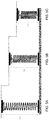
FIG. 5(A-C) provides an illustration of an adaptive gap-filling component according to an embodiment.
FIG. 6(A-D) provides an illustration of an adaptive gap-filling component according to an embodiment.
FIG. 7(A-C) provides an illustration of an adaptive gap-filling component according to an embodiment.
FIG. 8(A-B) provides an illustration of an adaptive gap-filling component according to an embodiment.
DETAILED DESCRIPTION
It will be readily understood that the components of the embodiments, as generally described and illustrated in the figures herein, may be arranged and designed in a wide variety of different configurations in addition to the described example embodiments. Thus, the following more detailed description of the example embodiments, as represented in the figures, is not intended to limit the scope of the embodiments, as claimed, but is merely representative of example embodiments.
Reference throughout this specification to “one embodiment” or “an embodiment” (or the like) means that a particular feature, structure, or characteristic described in connection with the embodiment is included in at least one embodiment. Thus, the appearance of the phrases “in one embodiment” or “in an embodiment” or the like in various places throughout this specification are not necessarily all referring to the same embodiment.
Furthermore, the described features, structures, or characteristics may be combined in any suitable manner in one or more embodiments. In the following description, numerous specific details are provided to give a thorough understanding of embodiments. One skilled in the relevant art will recognize, however, that the various embodiments can be practiced without one or more of the specific details, or with other methods, components, materials, et cetera. In other instances, well known structures, materials, or operations are not shown or described in detail to avoid obfuscation.
Situations arise where a battery pack (“battery”) swells. In these instances, a number of negative effects may occur. For example, the battery may stop working, the battery may bulge and/or bubble, the swelling may damage the device housing the battery, and, in extreme situations, the battery may explode, potentially harming a user. A variety of different factors may contribute to battery swelling such as, inter alia, aging during storage, time at full charge voltage, exposure to high temperature (e.g., when a device is left in the sun on a hot day, etc.), cycling count, manufacturing defects, poor cell quality and design, mechanical damage to electrodes due to mishandling, deep discharge of cells, and the like.
Due to the foregoing, the detection of battery swelling is important for ensuring that the device housing the battery is not damaged and/or for ensuring that users are not harmed when interacting with their device. Accordingly, pressure sensors currently exist that are integral to the battery and can detect when swelling occurs. For example, with reference to FIG. 1A, a battery 10 is illustrated that contains a pressure sensor 11. When the battery 10 swells, as illustrated in FIG. 1B, the sensor 11 may come into contact with a system lining 12, at which point the sensor 11 may record data associated with the detected swelling event. This information may thereafter be communicated to the user (e.g., in an emergency notification, etc.) and/or may be utilized by the device (e.g., to perform a dynamic shut down, etc.).
Issues exist, however, with conventional implementations of battery-based pressure sensors. Specifically, the current configurations do not account for the presence of a gap 13, as shown in FIG. 1A, between the battery 11 and the system lining 12. The presence of this gap 13 results in undetected swelling by the pressure sensor 11. More particularly, in order for the pressure sensor 11 to come into contact with the system lining 12, the battery 10 must swell by a certain degree. Consequently, because data related to the swelling only begins to be recorded when the pressure sensor 11 comes into contact with the system lining 12, any swelling by the battery 10 before this point goes undetected.
The effects of the aforementioned gap are further visualized by reference to FIG. 2. Specifically, the graph in FIG. 2 illustrates the difference between how much the battery has actually swelled 21 versus what the pressure sensor detects 22 at the point at which the battery comes into contact with the system lining. In the graph, it can be seen that the battery has actually swelled by about 17% at the touching point whereas the sensor only records that minimal swelling has occurred. The difference between the actual 21 versus detected 22 swelling percentage may be at least partially dependent upon the size of the gap (i.e., the greater the gap size the greater difference between the actual versus detected swelling percentage).
Accordingly, an embodiment provides a method and configuration for more accurately detecting battery swelling. In an embodiment, a swelling event associated with a battery may be detected by a pressure sensor integrated into a surface lining of the battery. Detection of the swelling event may be further facilitated by the presence of at least one adaptive gap-filling component. The adaptive gap-filling component may take one of a variety of different forms and may be situated between the surface lining of the battery and a wall of the electronic device that at least partially surrounds the battery. As the battery swells and expands into the adaptive gap-filling component, the component may dynamically adjust its length in response to the force of the swelling. The presence of such a component may therefore help “zero” the pressure sensor and allow it to record more accurate swelling readings.
The illustrated example embodiments will be best understood by reference to the figures. The following description is intended only by way of example, and simply illustrates certain example embodiments.
Referring now to FIG. 3(A-B), the effects that an adaptive gap-filling component has on the accuracy of swelling detection is illustrated. With respect to FIG. 3A, a generic representation of an adaptive gap-filling component 31 placed between a pressure sensor 32 and a wall 33 of the system/electronic device is provided. In an embodiment, the pressure sensor 32 may be integrated into a surface lining of a battery 34. The battery 34 may be virtually any type of battery that is susceptible to swelling and/or bulging (e.g., a lithium-ion battery pack, etc.). In an embodiment, the electronic device may be virtually any electronic device that is capable of supporting and/or drawing power from a swelling-susceptible battery (e.g., a smart phone, tablet, laptop, etc.).
As can be seen from the figure, the adaptive gap-filling component 31 may serve to bridge the gap that is present in conventional configurations (i.e., as shown in FIG. 1A). In an embodiment, the adaptive gap-filling component may be specially designed to fit an exact gap distance (e.g., for a particular battery pack/electronic device pair, etc.). Additionally or alternatively, the adaptive-gap filling component may be designed to be dynamic to fit a variety of different gap distances that may be present in differing battery/electronic device pairs (e.g., from gap sizes ranging from 0.5 mm-5 mm, etc.).
In either of the component designs described in the previous paragraph, a length of the adaptive gap-filling component may be adjustable (e.g., similar to a spring, etc.). The flexible nature of this component may ensure that it is lengthy enough to appropriately fill the gap (i.e., by expanding in length to fit the dimensions of the gap). Additionally, manufacturers may take advantage of this flexibility during the component installation. For example, in this case of a spring-like component, a length of the component may be originally decreased, e.g., by applying a force to one or both ends of the component, when the component is placed between the pressure sensor and a wall surrounding the battery. Once inserted, the applied forces may be removed and the component may naturally expand to fit the dimensions of the gap. Additionally or alternatively, the inserted components may thereafter substantially solidify in place and may thereby allow the pressure sensor to better detect early swelling.
The presence of this component may help to “auto-zero” the pressure sensor, thereby allowing it to more accurately track the actual swelling experienced by the battery. More particularly, when swelling occurs, the pressure sensor is forced against the gap-filling component, thereby allowing the pressure sensor to receive an indication of pressure much earlier than what would have been detected in conventional designs (i.e., due to the pressure sensor expanding into an empty gap).
The improvements in swelling detection resulting from utilization of the adaptive gap-filling component may become more apparent upon an examination of the graph provided in FIG. 3B. As can be seen from the graph, the adaptive pressure sensor (i.e., the pressure sensor utilized in combination with the adaptive gap-filling component) produces a graph plot 35 that is much closer to a graph plot 36 produced by the actual swelling of the battery than a graph plot 37 produced by conventional techniques known in the art. More particularly, during the early stages of swelling, the adaptive pressure sensor substantially exactly tracks the process of actual swelling. As swelling progresses and the battery lining approaches the touching point (i.e., the system/device wall surrounding the battery), the accuracy of the adaptive pressure sensor tapers off because, inter alia, a length of the gap-filling component can only contract so far, thereby preventing the pressure sensor from expanding naturally with the battery to the touching point and beyond.
Early stage swelling detection accuracy, achieved by the embodiments described herein, is very important to mitigate damage caused to the device and/or a user of the device. In certain embodiments, the pressure sensor may transmit (e.g., wirelessly, etc.) the swelling data to one or more processors of the device it is housed in, which may thereafter utilize that data to perform one or more downstream functions. For example, upon receipt of the swelling data, an embodiment may provide an alert notification to a user (e.g., that battery swelling is occurring, etc.). Additionally or alternatively, an embodiment may keep track of and record the data in an accessible storage database (e.g., stored locally on the device, etc.). Additionally or alternatively, an embodiment may dynamically initiate a power-off function (e.g., responsive to detecting that a rate of or a degree of swelling has exceeded a predetermined threshold, etc.).
The subsequent figures illustrate various types of potential gap-filling components that may be consistent with the embodiment described herein. It is important to note that the types of gap-filling components that are illustrated and described herein are not limiting and other types of gap-filling components, not explicitly illustrated and described here, may also be utilized.
FIG. 4(A-C) illustrates an embodiment in which the adaptive gap-filling component corresponds to a spring piezoresistive sensor. The sensor of this embodiment may contain at least two arms 41, as annotated in FIG. 4A, that are able to detect mechanical strain (i.e., produced from the swelling of the battery). These arms may be adjustable (e.g., as shown from FIG. 4A to FIG. 4C) to accommodate the size of a gap. Additionally, as swelling occurs, the arms may correspondingly flatten to accommodate for the swelling of the battery.
FIG. 5(A-C) illustrates a similar concept wherein the adaptive gap-filling component corresponds to a simple spring configuration. As in FIG. 4(A-C), the spring configuration may adjust in length responsive to increasing mechanical strain and may be manipulated to fit a number of different gap sizes. In an embodiment, the spring may be composed of a polymer base (e.g., similar to epoxy, etc.). The composition of this embodiment allows the spring to be adjustable in length during installation (i.e., to expand/fit to a gap of a particular size) but may thereafter harden once it has settled into the gap. This “delayed thermosetting” property of the spring may allow the pressure sensor to better detect swelling (i.e., by contacting the solidified gap-filling component during battery swelling).
FIG. 6(A-D) illustrates an embodiment in which the adaptive gap-filling component corresponds to an adaptive air-dry polymer spring configuration. Referring to FIG. 6A, a non-limiting example representation of the air-dry polymer component in its naturally expanded state is illustrated. This component may contain a polyurethane base 61 that may consist of at least five component materials (i.e., polyols, sulfactants, catalyst, blowing agents, and fire retardents). During installation, the component may be contracted to fit a needed gap size (as illustrated in FIGS. 6(B-D)) at which point a bottom portion 62 of the component may penetrate the polyurethane base, as shown in FIG. 6C. This penetration initiates a chemical reaction that may allow the component to solidify to robustly fit to the gap space once component movement (i.e., expansion and/or contraction) has stopped.
FIG. 7(A-C) illustrates an embodiment in which the adaptive gap-filling component corresponds to adaptive self-expanding foam. Similar to the embodiments illustrated in FIGS. 5 and 6, the foam may exhibit some delayed solidification properties. More particularly, the foam may contain some glue-type material that may originally be more fluid-like during component installation (i.e., into the gap space). Once the component expands to appropriately fill the gap space, the component may thereafter harden and solidify.
FIG. 8(A-B) illustrates an embodiment in which the adaptive gap-filling component corresponds to a corrugated/accordion-shaped adjustable pipe. Similar to some of the foregoing embodiments, this corrugated component may be adjustable to a desired gap size during installation. More particularly, as shown in FIG. 8A, a force may be applied to the component that allows it to be appropriately sized to a particular gap. In an embodiment, an inner portion 81 of the component may contain a pre-mixed gel, as shown in FIG. 8B, that contains at least five components (i.e., polyols, sulfactants, catalyst, blowing agents, and fire retardants). The implementation of the sizing force may initiate a chemical reaction in the pre-mixed gel which solidifies the component in place once the desired size is achieved.
It is important to note that although the foregoing implementations of the adaptive gap-filling component are described with reference to a battery pack, these descriptions are not limiting. More particularly, the foregoing concepts may be utilized in any application that requires sensors to detect swelling and/or movement of a device component.
The various embodiments described herein thus represent a technical improvement to conventional techniques for detecting battery swelling. More particularly, embodiments of the foregoing provide an adaptive gap-filling component that may be positioned in a gap located between a battery and a system wall that surrounds the battery. The implementation of this component may allow a pressure sensor located at a surface of the battery to more accurately and quickly detect a swelling event.
As used herein, the singular “a” and “an” may be construed as including the plural “one or more” unless clearly indicated otherwise.
This disclosure has been presented for purposes of illustration and description but is not intended to be exhaustive or limiting. Many modifications and variations will be apparent to those of ordinary skill in the art. The example embodiments were chosen and described in order to explain principles and practical application, and to enable others of ordinary skill in the art to understand the disclosure for various embodiments with various modifications as are suited to the particular use contemplated.
Thus, although illustrative example embodiments have been described herein with reference to the accompanying figures, it is to be understood that this description is not limiting and that various other changes and modifications may be affected therein by one skilled in the art without departing from the scope or spirit of the disclosure.

Claims (11)

What is claimed is:
1. An electronic device, comprising:
a device component; and
at least one adaptive gap-filling component situated in a gap between a surface lining of the device component and an inner wall of the electronic device that at least partially surrounds the device component;
wherein the at least one adaptive gap-filling component comprises a pressure sensor and a mechanical arm;
wherein the mechanical arm is adjustable to span the gap between the surface lining of the device component and the inner wall of the electronic device;
wherein the pressure sensor detects turning of the mechanical arm in response to swelling of the device component and wherein a length of the mechanical arm is fixed.
2. The electronic device of claim 1, wherein a length of the at least one adaptive gap-filling component is configured to be adjusted responsive to swelling of the device component.
3. The electronic device of claim 2, wherein the pressure sensor is configured to communicate data associated with the swelling to the electronic device.
4. The electronic device of claim 3, wherein the electronic device further comprises:
a processor;
a memory device that stores instructions executable by the processor to:
utilize the data to perform a function selected from the group consisting of: a user-notification function, a data recordation function, and a dynamic shutoff function.
5. The electronic device of claim 1, wherein the pressure sensor in the at least one adaptive gap-filling component is an adaptive spring piezoresistive sensor.
6. A method, comprising:
detecting, using a pressure sensor integrated into at least one adaptive gap-filling, a swelling event associated with a device component housed within an electronic device, wherein the at least one gap-filling component further comprises a mechanical arm and is situated in a gap between a surface lining of the device component and an inner wall of the electronic device that at least partially surrounds the device component;
wherein the detecting comprises identifying a turning of the mechanical arm;
wherein the mechanical arm is adjustable to span the gap between the surface lining of the device component and the inner wall of the electronic device;
wherein a length of the mechanical arm is fixed.
7. The method of claim 6, wherein a length of the at least one adaptive gap-filling component is configured to be adjusted responsive to swelling of the device component.
8. The method of claim 7, wherein the pressure sensor is configured to communicate data associated with the swelling to the electronic device.
9. The method of claim 8, further comprising utilizing the data to perform a function selected from the group consisting of: a user-notification function, a data recordation function, and a dynamic shutoff function.
10. The method of claim 1, wherein the pressure sensor in the at least one adaptive gap-filling component is an adaptive spring piezoresistive sensor.
11. A method, comprising:
auto-zeroing a pressure sensor integrated into at least one adaptive gap-filling component, wherein the auto-zeroing comprises:
introducing the at least one adaptive gap-filling component into a gap between a surface lining of a device component housed within an electronic device and an inner wall of the electronic device that at least partially surrounds the device component;
wherein the at least one adaptive gap-filling component comprises a pressure sensor and a mechanical arm;
wherein the mechanical arm is adjustable to span the gap between the surface lining of the device component and the inner wall of the electronic device;
wherein the pressure sensor detects turning of the mechanical arm in response to swelling of the device component and wherein a length of the mechanical arm is fixed.
US16/795,956 2020-02-20 2020-02-20 Device component swelling detection Active US11215519B2 (en)

Priority Applications (1)

Application Number Priority Date Filing Date Title
US16/795,956 US11215519B2 (en) 2020-02-20 2020-02-20 Device component swelling detection

Applications Claiming Priority (1)

Application Number Priority Date Filing Date Title
US16/795,956 US11215519B2 (en) 2020-02-20 2020-02-20 Device component swelling detection

Publications (2)

Publication Number Publication Date
US20210262883A1 US20210262883A1 (en) 2021-08-26
US11215519B2 true US11215519B2 (en) 2022-01-04

Family

ID=77365997

Family Applications (1)

Application Number Title Priority Date Filing Date
US16/795,956 Active US11215519B2 (en) 2020-02-20 2020-02-20 Device component swelling detection

Country Status (1)

Country Link
US (1) US11215519B2 (en)

Families Citing this family (2)

* Cited by examiner, † Cited by third party
Publication number Priority date Publication date Assignee Title
DE102020130834A1 (en) * 2020-11-23 2022-05-25 Audi Aktiengesellschaft Energy storage device for storing electrical energy, method for operating an energy storage device and motor vehicle
US20230147262A1 (en) * 2021-11-09 2023-05-11 Hand Held Products, Inc. Battery fault detection assemblies

Citations (29)

* Cited by examiner, † Cited by third party
Publication number Priority date Publication date Assignee Title
US6271644B1 (en) * 1999-06-22 2001-08-07 Hudson Soft, Co., Ltd. Battery pack
US20050092329A1 (en) * 2003-10-29 2005-05-05 Sta-Maria Rosalinda C. Nasal continuous positive airway pressure cannula device and securement for infants
US20060181517A1 (en) * 2005-02-11 2006-08-17 Apple Computer, Inc. Display actuator
US20070054157A1 (en) * 2005-09-07 2007-03-08 Ryu Ji H Secondary battery employing safety device
US20120208054A1 (en) * 2011-02-16 2012-08-16 Toyota Jidosha Kabushiki Kaisha Battery system and battery structure
US20140002269A1 (en) * 2012-06-28 2014-01-02 Xunwei Zhou Detection of swelling in batteries
US20140042961A1 (en) * 2012-08-12 2014-02-13 Compal Electronics, Inc. Electronic Device and Method for Detecting Swelling of Battery Thereof
US8758920B2 (en) * 2007-03-08 2014-06-24 Nikon Corporation Battery accommodating device, portable device, output device, and head mount display
US20150171410A1 (en) * 2013-12-18 2015-06-18 Hyundai Motor Company Apparatus for preventing over-charge for battery of vehicle
US20160064780A1 (en) * 2014-08-28 2016-03-03 Apple Inc. Methods for determining and controlling battery expansion
US20170077561A1 (en) * 2014-06-30 2017-03-16 Toyo Tire & Rubber Co., Ltd. Method for determining abnormality in assembled battery, and device for determining abnormality in assembled battery
US20170108326A1 (en) * 2015-10-16 2017-04-20 Chroma Ate Inc. Measurement fixture for a battery cell
US20170288283A1 (en) * 2014-11-25 2017-10-05 Toyo Tire & Rubber Co., Ltd. Sensor for detecting deformation of sealed secondary battery
US20170309973A1 (en) * 2016-04-20 2017-10-26 Robert Bosch Gmbh Length expansion monitoring for determining the aging of a battery cell or a battery module
US20170331157A1 (en) * 2016-05-13 2017-11-16 NextEv USA, Inc. Battery module having a pressure sensor
US20180226698A1 (en) * 2017-02-03 2018-08-09 Omron Corporation Abnormality detector
US20180261824A1 (en) * 2017-03-10 2018-09-13 Samsung Electronics Co., Ltd. Method of detecting swelling of battery using pressure sensor and electronic device using the method
US10230136B2 (en) * 2014-06-27 2019-03-12 Toyo Tire Corporation Monitoring sensor including a polymer matrix for monitoring a sealed secondary battery, sealed secondary battery including the monitoring sensor, and monitoring method for sealed secondary battery
US10355319B1 (en) * 2016-08-04 2019-07-16 Amazon Technologies, Inc. Methods and systems for improved battery performance
US20190227125A1 (en) * 2016-08-19 2019-07-25 Toyo Tire Corporation Assembled battery manufacturing method using used batteries, and assembled battery
US20190249979A1 (en) * 2016-10-28 2019-08-15 Toyo Tire Corporation Deformation detection sensor for sealed secondary battery and sealed secondary battery
US10476068B2 (en) * 2015-10-06 2019-11-12 Lg Chem, Ltd. Battery module including probe for detecting expansion of battery cell
US20190363392A1 (en) * 2017-09-18 2019-11-28 Lg Chem, Ltd. Battery module and battery pack including same
US20200168959A1 (en) * 2017-07-21 2020-05-28 Quantumscape Corporation Active and passive battery pressure management
US20200185166A1 (en) * 2016-09-13 2020-06-11 Panasonic Intellectual Property Management Co., Ltd. Push switch
US20200203783A1 (en) * 2018-12-21 2020-06-25 Lenovo (Singapore) Pte. Ltd. Battery swelling detection
US20200227793A1 (en) * 2017-12-26 2020-07-16 Lg Chem, Ltd. Cylindrical battery having pressure sensor, and method for measuring internal pressure thereof
US20200239291A1 (en) * 2019-01-25 2020-07-30 Jungheinrich Aktiengesellschaft Industrial truck with stand-on platform
US20200358440A1 (en) * 2019-05-07 2020-11-12 Dell Products, Lp System and method for integrating components of an electro-permanent magnet key switch assembly

Patent Citations (29)

* Cited by examiner, † Cited by third party
Publication number Priority date Publication date Assignee Title
US6271644B1 (en) * 1999-06-22 2001-08-07 Hudson Soft, Co., Ltd. Battery pack
US20050092329A1 (en) * 2003-10-29 2005-05-05 Sta-Maria Rosalinda C. Nasal continuous positive airway pressure cannula device and securement for infants
US20060181517A1 (en) * 2005-02-11 2006-08-17 Apple Computer, Inc. Display actuator
US20070054157A1 (en) * 2005-09-07 2007-03-08 Ryu Ji H Secondary battery employing safety device
US8758920B2 (en) * 2007-03-08 2014-06-24 Nikon Corporation Battery accommodating device, portable device, output device, and head mount display
US20120208054A1 (en) * 2011-02-16 2012-08-16 Toyota Jidosha Kabushiki Kaisha Battery system and battery structure
US20140002269A1 (en) * 2012-06-28 2014-01-02 Xunwei Zhou Detection of swelling in batteries
US20140042961A1 (en) * 2012-08-12 2014-02-13 Compal Electronics, Inc. Electronic Device and Method for Detecting Swelling of Battery Thereof
US20150171410A1 (en) * 2013-12-18 2015-06-18 Hyundai Motor Company Apparatus for preventing over-charge for battery of vehicle
US10230136B2 (en) * 2014-06-27 2019-03-12 Toyo Tire Corporation Monitoring sensor including a polymer matrix for monitoring a sealed secondary battery, sealed secondary battery including the monitoring sensor, and monitoring method for sealed secondary battery
US20170077561A1 (en) * 2014-06-30 2017-03-16 Toyo Tire & Rubber Co., Ltd. Method for determining abnormality in assembled battery, and device for determining abnormality in assembled battery
US20160064780A1 (en) * 2014-08-28 2016-03-03 Apple Inc. Methods for determining and controlling battery expansion
US20170288283A1 (en) * 2014-11-25 2017-10-05 Toyo Tire & Rubber Co., Ltd. Sensor for detecting deformation of sealed secondary battery
US10476068B2 (en) * 2015-10-06 2019-11-12 Lg Chem, Ltd. Battery module including probe for detecting expansion of battery cell
US20170108326A1 (en) * 2015-10-16 2017-04-20 Chroma Ate Inc. Measurement fixture for a battery cell
US20170309973A1 (en) * 2016-04-20 2017-10-26 Robert Bosch Gmbh Length expansion monitoring for determining the aging of a battery cell or a battery module
US20170331157A1 (en) * 2016-05-13 2017-11-16 NextEv USA, Inc. Battery module having a pressure sensor
US10355319B1 (en) * 2016-08-04 2019-07-16 Amazon Technologies, Inc. Methods and systems for improved battery performance
US20190227125A1 (en) * 2016-08-19 2019-07-25 Toyo Tire Corporation Assembled battery manufacturing method using used batteries, and assembled battery
US20200185166A1 (en) * 2016-09-13 2020-06-11 Panasonic Intellectual Property Management Co., Ltd. Push switch
US20190249979A1 (en) * 2016-10-28 2019-08-15 Toyo Tire Corporation Deformation detection sensor for sealed secondary battery and sealed secondary battery
US20180226698A1 (en) * 2017-02-03 2018-08-09 Omron Corporation Abnormality detector
US20180261824A1 (en) * 2017-03-10 2018-09-13 Samsung Electronics Co., Ltd. Method of detecting swelling of battery using pressure sensor and electronic device using the method
US20200168959A1 (en) * 2017-07-21 2020-05-28 Quantumscape Corporation Active and passive battery pressure management
US20190363392A1 (en) * 2017-09-18 2019-11-28 Lg Chem, Ltd. Battery module and battery pack including same
US20200227793A1 (en) * 2017-12-26 2020-07-16 Lg Chem, Ltd. Cylindrical battery having pressure sensor, and method for measuring internal pressure thereof
US20200203783A1 (en) * 2018-12-21 2020-06-25 Lenovo (Singapore) Pte. Ltd. Battery swelling detection
US20200239291A1 (en) * 2019-01-25 2020-07-30 Jungheinrich Aktiengesellschaft Industrial truck with stand-on platform
US20200358440A1 (en) * 2019-05-07 2020-11-12 Dell Products, Lp System and method for integrating components of an electro-permanent magnet key switch assembly

Also Published As

Publication number Publication date
US20210262883A1 (en) 2021-08-26

Similar Documents

Publication Publication Date Title
US11215519B2 (en) Device component swelling detection
US11329328B2 (en) Abnormality detector
Sahraei et al. Modeling and short circuit detection of 18650 Li-ion cells under mechanical abuse conditions
US10355319B1 (en) Methods and systems for improved battery performance
TW201407179A (en) Electronic device and method for detecting swelling of battery thereof
EP2827436B1 (en) Electronic device and methods therein
CN110285749B (en) Battery pack explosion-proof detection method, explosion-proof detection device and battery pack
US11143708B2 (en) Electronic device and method for obtaining a correct battery temperature
WO2004109708A3 (en) Nanoelectromechanical memory cells and data storage devices
US11150170B2 (en) Apparatus and method for measuring deformation stiffness of a secondary battery
KR20170050926A (en) A secondary battery, secondary battery charging system and secondary battery production method to prevent battery cell swelling by detecting a displacement of gas venting unit
US10741883B2 (en) Detecting abnormal condition(s) associated with flexible, pouch-type energy storage device
CN108414943B (en) Battery detection device and method and battery pack system
US11264650B2 (en) Apparatus and method for testing end plate
KR20130063207A (en) Apparatus and method for measuring inner pressure of secondary battery
US8756025B2 (en) Temperature sensing of electric batteries
US20220099749A1 (en) Battery Degradation Monitoring System and Methods
JP2013080634A (en) Measuring method and measuring system of secondary battery
US20140190241A1 (en) Deflection Sensitive Coolant Activated Drain Plug Detection System For High Voltage Battery Packs
CN104730465B (en) Lithium ion battery detection system and detection method adopting same
Kirchev et al. Li-Ion Cell Safety Monitoring Using Mechanical Parameters: Part II. Battery Behavior during Thermal Abuse Tests
TWI797812B (en) Battery detection device and method therefor
US8656794B2 (en) Apparatus for dissolution experiment of mineral
KR20220147253A (en) Pressure measuring device and pressure measuring method of pouch-type battery cells
KR20200047183A (en) Tape For Secondary Battery And Lithium Ion Battery Using Same

Legal Events

Date Code Title Description
AS Assignment

Owner name: LENOVO (SINGAPORE) PTE. LTD., SINGAPORE

Free format text: ASSIGNMENT OF ASSIGNORS INTEREST;ASSIGNORS:YEBKA, BOUZIANE;WONG, TIN-LUP;JAKES, PHILIP JOHN;REEL/FRAME:051872/0708

Effective date: 20200218

FEPP Fee payment procedure

Free format text: ENTITY STATUS SET TO UNDISCOUNTED (ORIGINAL EVENT CODE: BIG.); ENTITY STATUS OF PATENT OWNER: LARGE ENTITY

STPP Information on status: patent application and granting procedure in general

Free format text: NOTICE OF ALLOWANCE MAILED -- APPLICATION RECEIVED IN OFFICE OF PUBLICATIONS

STPP Information on status: patent application and granting procedure in general

Free format text: PUBLICATIONS -- ISSUE FEE PAYMENT VERIFIED

STCF Information on status: patent grant

Free format text: PATENTED CASE