US11215208B2 - Positioning locking mechanism of rotational member - Google Patents
Positioning locking mechanism of rotational member Download PDFInfo
- Publication number
- US11215208B2 US11215208B2 US16/144,091 US201816144091A US11215208B2 US 11215208 B2 US11215208 B2 US 11215208B2 US 201816144091 A US201816144091 A US 201816144091A US 11215208 B2 US11215208 B2 US 11215208B2
- Authority
- US
- United States
- Prior art keywords
- positioning
- rotational
- locking
- groove
- locking operation
- Prior art date
- Legal status (The legal status is an assumption and is not a legal conclusion. Google has not performed a legal analysis and makes no representation as to the accuracy of the status listed.)
- Active, expires
Links
- 230000007246 mechanism Effects 0.000 title claims abstract description 34
- 238000009434 installation Methods 0.000 claims description 36
- 230000000694 effects Effects 0.000 claims description 11
- 230000000670 limiting effect Effects 0.000 claims description 8
- 230000004888 barrier function Effects 0.000 claims description 4
- 238000013016 damping Methods 0.000 description 19
- 238000010586 diagram Methods 0.000 description 13
- 238000005516 engineering process Methods 0.000 description 7
- 239000000463 material Substances 0.000 description 7
- 239000004033 plastic Substances 0.000 description 6
- 230000006870 function Effects 0.000 description 4
- 230000008901 benefit Effects 0.000 description 3
- 230000008859 change Effects 0.000 description 3
- 230000007812 deficiency Effects 0.000 description 2
- 238000001746 injection moulding Methods 0.000 description 2
- 230000035807 sensation Effects 0.000 description 2
- 229910000831 Steel Inorganic materials 0.000 description 1
- 239000000654 additive Substances 0.000 description 1
- 230000000996 additive effect Effects 0.000 description 1
- 230000009286 beneficial effect Effects 0.000 description 1
- 230000007547 defect Effects 0.000 description 1
- 238000006073 displacement reaction Methods 0.000 description 1
- 239000003365 glass fiber Substances 0.000 description 1
- 238000000034 method Methods 0.000 description 1
- 230000003014 reinforcing effect Effects 0.000 description 1
- 239000000243 solution Substances 0.000 description 1
- 230000006641 stabilisation Effects 0.000 description 1
- 238000011105 stabilization Methods 0.000 description 1
- 239000010959 steel Substances 0.000 description 1
- 239000000126 substance Substances 0.000 description 1
Images


Classifications
-
- F—MECHANICAL ENGINEERING; LIGHTING; HEATING; WEAPONS; BLASTING
- F16—ENGINEERING ELEMENTS AND UNITS; GENERAL MEASURES FOR PRODUCING AND MAINTAINING EFFECTIVE FUNCTIONING OF MACHINES OR INSTALLATIONS; THERMAL INSULATION IN GENERAL
- F16M—FRAMES, CASINGS OR BEDS OF ENGINES, MACHINES OR APPARATUS, NOT SPECIFIC TO ENGINES, MACHINES OR APPARATUS PROVIDED FOR ELSEWHERE; STANDS; SUPPORTS
- F16M13/00—Other supports for positioning apparatus or articles; Means for steadying hand-held apparatus or articles
- F16M13/04—Other supports for positioning apparatus or articles; Means for steadying hand-held apparatus or articles for supporting on, or holding steady relative to, a person, e.g. by chains, e.g. rifle butt or pistol grip supports, supports attached to the chest or head
-
- F—MECHANICAL ENGINEERING; LIGHTING; HEATING; WEAPONS; BLASTING
- F16—ENGINEERING ELEMENTS AND UNITS; GENERAL MEASURES FOR PRODUCING AND MAINTAINING EFFECTIVE FUNCTIONING OF MACHINES OR INSTALLATIONS; THERMAL INSULATION IN GENERAL
- F16C—SHAFTS; FLEXIBLE SHAFTS; ELEMENTS OR CRANKSHAFT MECHANISMS; ROTARY BODIES OTHER THAN GEARING ELEMENTS; BEARINGS
- F16C11/00—Pivots; Pivotal connections
- F16C11/04—Pivotal connections
- F16C11/10—Arrangements for locking
- F16C11/103—Arrangements for locking frictionally clamped
-
- F—MECHANICAL ENGINEERING; LIGHTING; HEATING; WEAPONS; BLASTING
- F16—ENGINEERING ELEMENTS AND UNITS; GENERAL MEASURES FOR PRODUCING AND MAINTAINING EFFECTIVE FUNCTIONING OF MACHINES OR INSTALLATIONS; THERMAL INSULATION IN GENERAL
- F16B—DEVICES FOR FASTENING OR SECURING CONSTRUCTIONAL ELEMENTS OR MACHINE PARTS TOGETHER, e.g. NAILS, BOLTS, CIRCLIPS, CLAMPS, CLIPS OR WEDGES; JOINTS OR JOINTING
- F16B2/00—Friction-grip releasable fastenings
- F16B2/02—Clamps, i.e. with gripping action effected by positive means other than the inherent resistance to deformation of the material of the fastening
- F16B2/06—Clamps, i.e. with gripping action effected by positive means other than the inherent resistance to deformation of the material of the fastening external, i.e. with contracting action
- F16B2/10—Clamps, i.e. with gripping action effected by positive means other than the inherent resistance to deformation of the material of the fastening external, i.e. with contracting action using pivoting jaws
-
- F—MECHANICAL ENGINEERING; LIGHTING; HEATING; WEAPONS; BLASTING
- F16—ENGINEERING ELEMENTS AND UNITS; GENERAL MEASURES FOR PRODUCING AND MAINTAINING EFFECTIVE FUNCTIONING OF MACHINES OR INSTALLATIONS; THERMAL INSULATION IN GENERAL
- F16B—DEVICES FOR FASTENING OR SECURING CONSTRUCTIONAL ELEMENTS OR MACHINE PARTS TOGETHER, e.g. NAILS, BOLTS, CIRCLIPS, CLAMPS, CLIPS OR WEDGES; JOINTS OR JOINTING
- F16B2/00—Friction-grip releasable fastenings
- F16B2/02—Clamps, i.e. with gripping action effected by positive means other than the inherent resistance to deformation of the material of the fastening
- F16B2/18—Clamps, i.e. with gripping action effected by positive means other than the inherent resistance to deformation of the material of the fastening using cams, levers, eccentrics, or toggles
- F16B2/185—Clamps, i.e. with gripping action effected by positive means other than the inherent resistance to deformation of the material of the fastening using cams, levers, eccentrics, or toggles using levers
-
- F—MECHANICAL ENGINEERING; LIGHTING; HEATING; WEAPONS; BLASTING
- F16—ENGINEERING ELEMENTS AND UNITS; GENERAL MEASURES FOR PRODUCING AND MAINTAINING EFFECTIVE FUNCTIONING OF MACHINES OR INSTALLATIONS; THERMAL INSULATION IN GENERAL
- F16B—DEVICES FOR FASTENING OR SECURING CONSTRUCTIONAL ELEMENTS OR MACHINE PARTS TOGETHER, e.g. NAILS, BOLTS, CIRCLIPS, CLAMPS, CLIPS OR WEDGES; JOINTS OR JOINTING
- F16B7/00—Connections of rods or tubes, e.g. of non-circular section, mutually, including resilient connections
- F16B7/04—Clamping or clipping connections
- F16B7/0406—Clamping or clipping connections for rods or tubes being coaxial
- F16B7/0413—Clamping or clipping connections for rods or tubes being coaxial for tubes using the innerside thereof
- F16B7/042—Clamping or clipping connections for rods or tubes being coaxial for tubes using the innerside thereof with a locking element, e.g. pin, ball or pushbutton, engaging in a hole in the wall of at least one tube
-
- F—MECHANICAL ENGINEERING; LIGHTING; HEATING; WEAPONS; BLASTING
- F16—ENGINEERING ELEMENTS AND UNITS; GENERAL MEASURES FOR PRODUCING AND MAINTAINING EFFECTIVE FUNCTIONING OF MACHINES OR INSTALLATIONS; THERMAL INSULATION IN GENERAL
- F16C—SHAFTS; FLEXIBLE SHAFTS; ELEMENTS OR CRANKSHAFT MECHANISMS; ROTARY BODIES OTHER THAN GEARING ELEMENTS; BEARINGS
- F16C11/00—Pivots; Pivotal connections
- F16C11/04—Pivotal connections
- F16C11/06—Ball-joints; Other joints having more than one degree of angular freedom, i.e. universal joints
- F16C11/0661—Ball-joints; Other joints having more than one degree of angular freedom, i.e. universal joints the two co-operative parts each having both convex and concave interfaces
-
- F—MECHANICAL ENGINEERING; LIGHTING; HEATING; WEAPONS; BLASTING
- F16—ENGINEERING ELEMENTS AND UNITS; GENERAL MEASURES FOR PRODUCING AND MAINTAINING EFFECTIVE FUNCTIONING OF MACHINES OR INSTALLATIONS; THERMAL INSULATION IN GENERAL
- F16C—SHAFTS; FLEXIBLE SHAFTS; ELEMENTS OR CRANKSHAFT MECHANISMS; ROTARY BODIES OTHER THAN GEARING ELEMENTS; BEARINGS
- F16C11/00—Pivots; Pivotal connections
- F16C11/04—Pivotal connections
- F16C11/10—Arrangements for locking
-
- F—MECHANICAL ENGINEERING; LIGHTING; HEATING; WEAPONS; BLASTING
- F16—ENGINEERING ELEMENTS AND UNITS; GENERAL MEASURES FOR PRODUCING AND MAINTAINING EFFECTIVE FUNCTIONING OF MACHINES OR INSTALLATIONS; THERMAL INSULATION IN GENERAL
- F16M—FRAMES, CASINGS OR BEDS OF ENGINES, MACHINES OR APPARATUS, NOT SPECIFIC TO ENGINES, MACHINES OR APPARATUS PROVIDED FOR ELSEWHERE; STANDS; SUPPORTS
- F16M11/00—Stands or trestles as supports for apparatus or articles placed thereon ; Stands for scientific apparatus such as gravitational force meters
- F16M11/02—Heads
- F16M11/04—Means for attachment of apparatus; Means allowing adjustment of the apparatus relatively to the stand
- F16M11/06—Means for attachment of apparatus; Means allowing adjustment of the apparatus relatively to the stand allowing pivoting
- F16M11/10—Means for attachment of apparatus; Means allowing adjustment of the apparatus relatively to the stand allowing pivoting around a horizontal axis
-
- F—MECHANICAL ENGINEERING; LIGHTING; HEATING; WEAPONS; BLASTING
- F16—ENGINEERING ELEMENTS AND UNITS; GENERAL MEASURES FOR PRODUCING AND MAINTAINING EFFECTIVE FUNCTIONING OF MACHINES OR INSTALLATIONS; THERMAL INSULATION IN GENERAL
- F16M—FRAMES, CASINGS OR BEDS OF ENGINES, MACHINES OR APPARATUS, NOT SPECIFIC TO ENGINES, MACHINES OR APPARATUS PROVIDED FOR ELSEWHERE; STANDS; SUPPORTS
- F16M11/00—Stands or trestles as supports for apparatus or articles placed thereon ; Stands for scientific apparatus such as gravitational force meters
- F16M11/20—Undercarriages with or without wheels
- F16M11/24—Undercarriages with or without wheels changeable in height or length of legs, also for transport only, e.g. by means of tubes screwed into each other
- F16M11/26—Undercarriages with or without wheels changeable in height or length of legs, also for transport only, e.g. by means of tubes screwed into each other by telescoping, with or without folding
- F16M11/28—Undercarriages for supports with one single telescoping pillar
-
- F—MECHANICAL ENGINEERING; LIGHTING; HEATING; WEAPONS; BLASTING
- F16—ENGINEERING ELEMENTS AND UNITS; GENERAL MEASURES FOR PRODUCING AND MAINTAINING EFFECTIVE FUNCTIONING OF MACHINES OR INSTALLATIONS; THERMAL INSULATION IN GENERAL
- F16M—FRAMES, CASINGS OR BEDS OF ENGINES, MACHINES OR APPARATUS, NOT SPECIFIC TO ENGINES, MACHINES OR APPARATUS PROVIDED FOR ELSEWHERE; STANDS; SUPPORTS
- F16M11/00—Stands or trestles as supports for apparatus or articles placed thereon ; Stands for scientific apparatus such as gravitational force meters
- F16M11/20—Undercarriages with or without wheels
- F16M11/24—Undercarriages with or without wheels changeable in height or length of legs, also for transport only, e.g. by means of tubes screwed into each other
- F16M11/38—Undercarriages with or without wheels changeable in height or length of legs, also for transport only, e.g. by means of tubes screwed into each other by folding, e.g. pivoting or scissors tong mechanisms
-
- F—MECHANICAL ENGINEERING; LIGHTING; HEATING; WEAPONS; BLASTING
- F16—ENGINEERING ELEMENTS AND UNITS; GENERAL MEASURES FOR PRODUCING AND MAINTAINING EFFECTIVE FUNCTIONING OF MACHINES OR INSTALLATIONS; THERMAL INSULATION IN GENERAL
- F16M—FRAMES, CASINGS OR BEDS OF ENGINES, MACHINES OR APPARATUS, NOT SPECIFIC TO ENGINES, MACHINES OR APPARATUS PROVIDED FOR ELSEWHERE; STANDS; SUPPORTS
- F16M13/00—Other supports for positioning apparatus or articles; Means for steadying hand-held apparatus or articles
- F16M13/02—Other supports for positioning apparatus or articles; Means for steadying hand-held apparatus or articles for supporting on, or attaching to, an object, e.g. tree, gate, window-frame, cycle
- F16M13/022—Other supports for positioning apparatus or articles; Means for steadying hand-held apparatus or articles for supporting on, or attaching to, an object, e.g. tree, gate, window-frame, cycle repositionable
-
- G—PHYSICS
- G03—PHOTOGRAPHY; CINEMATOGRAPHY; ANALOGOUS TECHNIQUES USING WAVES OTHER THAN OPTICAL WAVES; ELECTROGRAPHY; HOLOGRAPHY
- G03B—APPARATUS OR ARRANGEMENTS FOR TAKING PHOTOGRAPHS OR FOR PROJECTING OR VIEWING THEM; APPARATUS OR ARRANGEMENTS EMPLOYING ANALOGOUS TECHNIQUES USING WAVES OTHER THAN OPTICAL WAVES; ACCESSORIES THEREFOR
- G03B17/00—Details of cameras or camera bodies; Accessories therefor
- G03B17/56—Accessories
- G03B17/561—Support related camera accessories
-
- F—MECHANICAL ENGINEERING; LIGHTING; HEATING; WEAPONS; BLASTING
- F16—ENGINEERING ELEMENTS AND UNITS; GENERAL MEASURES FOR PRODUCING AND MAINTAINING EFFECTIVE FUNCTIONING OF MACHINES OR INSTALLATIONS; THERMAL INSULATION IN GENERAL
- F16M—FRAMES, CASINGS OR BEDS OF ENGINES, MACHINES OR APPARATUS, NOT SPECIFIC TO ENGINES, MACHINES OR APPARATUS PROVIDED FOR ELSEWHERE; STANDS; SUPPORTS
- F16M2200/00—Details of stands or supports
- F16M2200/02—Locking means
- F16M2200/021—Locking means for rotational movement
- F16M2200/024—Locking means for rotational movement by positive interaction, e.g. male-female connections
-
- F—MECHANICAL ENGINEERING; LIGHTING; HEATING; WEAPONS; BLASTING
- F16—ENGINEERING ELEMENTS AND UNITS; GENERAL MEASURES FOR PRODUCING AND MAINTAINING EFFECTIVE FUNCTIONING OF MACHINES OR INSTALLATIONS; THERMAL INSULATION IN GENERAL
- F16M—FRAMES, CASINGS OR BEDS OF ENGINES, MACHINES OR APPARATUS, NOT SPECIFIC TO ENGINES, MACHINES OR APPARATUS PROVIDED FOR ELSEWHERE; STANDS; SUPPORTS
- F16M2200/00—Details of stands or supports
- F16M2200/06—Arms
- F16M2200/068—Arms being part of the undercarriage
Definitions
- the present disclosure relates to the field of rotational positioning technology, and more particularly, to positioning locking mechanism of a rotational member.
- Rotational members are mechanical structures which are widely used, and partial rotational members in daily use need to be located at a designed angle, such as a movable supporting leg of a camera support, a cam lever of a quick locking device, etc., so as to meet the requirements of use.
- the present disclosure provides a technical scheme of positioning locking mechanism of a rotational member with simple operation and reliable locking, and the positioning locking mechanism effectively ensures that the positioning and locking of the rotational member will not be invalid due to accident collision or component fatigue.
- a positioning locking mechanism of a rotational member comprises a rotational positioning member provided with a positioning groove; a rotational member pivotally connected with the rotational positioning member and rotating around the rotational positioning member; a positioning member arranged in the rotational member, and meshed with or separated from the positioning groove through a locking operation member; wherein the positioning member is designed into a geometry adapted to and meshed with the locking operation member and the positioning groove; and the locking operation member arranged in the rotational member to control the positioning member to be meshed or separated; wherein the working mode of the locking operation member may be axial movement or radial rotation.
- the locking operation member is provided with an accommodating groove or an accommodating concave hole for containing the positioning member; wherein, when the locking operation member implements a locking motion, the positioning member is pushed up to enter the positioning groove under the rotational driving of the rotational member, the positioning member is kept to mesh with the positioning groove, and the rotational member cannot rotate to realize positioning and locking under the effect of the positioning member and the positioning groove; and when the locking operation member is operated to implement an unlocking motion, the locking operation member is pressed, the accommodating groove is moved to the position where the positioning member is located, and the positioning member falls into the accommodating groove to completely separate from the positioning groove, so that the rotational member can rotate to realize unlocking.
- the positioning locking mechanism of a rotational member has the beneficial effect that: the rotational positioning member is provided with the positioning groove, the rotational member is internally provided with the movable positioning member and the locking operation member, and the rotational positioning member realizes positioning and locking, or unlocking to the rotational member through the positioning member controlled by the locking operation member.
- the positioning locking mechanism according to the present disclosure abandons the positioning locking modes of bolt, pin, buckle, etc. in conventional technology, overcoming complicated operation, difficulty in quick locking and unlocking in conventional technology, and has the advantages of simple and compact structure, quick operation, firm locking and reliable installation and so on.
- FIG. 1 is a decomposed schematic diagram of an embodiment 1 according to the present disclosure
- FIG. 2 is another decomposed schematic diagram of the embodiment 1 according to the present disclosure, wherein a positioning groove is in a convex-hole shape;
- FIG. 3 is another decomposed schematic diagram of the embodiment 1 according to the present disclosure, wherein a positioning groove is a V-shape groove, and a positioning member has a cylinder with a V-shape end surface;
- FIG. 4 is a structural schematic diagram of a positioning locking mechanism in a positioning and locking state according to FIG. 3 ;
- FIG. 5 is a structural schematic diagram of the positioning locking mechanism in a positioning and locking state in the embodiment 1;
- FIG. 6 is a structural schematic diagram of the positioning locking mechanism in an unlocking state in the embodiment 1;
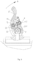
- FIG. 7 is a stereo chemical schematic diagram of an application example of the embodiment 1 in a quick locking device
- FIG. 8 is a main projection view of FIG. 7 ;
- FIG. 9 is a cross-section view of FIG. 8 ;
- FIG. 10 is a structural schematic diagram of a supporting leg
- FIG. 11 is a decomposed schematic diagram of the first example of an embodiment 2 according to the projection;
- FIG. 12 is an exploded assembly view at the location of a locking operation member in the first example of the embodiment 2 of the present disclosure
- FIG. 13 and FIG. 14 are structural schematic diagrams of the positioning locking mechanism in a positioning and locking state in the first example of the embodiment 2 of the present disclosure
- FIG. 15 is an A-A section view of FIG. 14 ;
- FIG. 16 is an exploded perspective view showing the second example of embodiment 2 of the present disclosure.
- FIG. 17 is a side cross-sectional view showing the second example of embodiment 2 of the present disclosure.
- FIG. 18 is a cross-sectional view taken along line A′-A′ of FIG. 17 ;
- FIG. 19A is a schematic diagram of the damper component in the second example of embodiment 2 of the present disclosure.
- FIG. 19B is a cross-sectional view taken along line A′′-A′′ of FIG. 19A ;
- FIG. 20A is a cross-sectional view of the cylinder in the second example of embodiment 2 of the present disclosure.
- FIG. 20B is a cross-sectional view taken along line A′′′-A′′′ of FIG. 20A ;
- FIG. 21 is an overall schematic diagram of the positioning locking mechanism in the embodiment 3 of the present disclosure.
- FIG. 22 is an exploded assembly view of the embodiment 3 according to the present disclosure.
- FIG. 23 is a section view of the embodiment 3 according to the present disclosure in a vertical locking state
- FIG. 24 is a section view of the embodiment 3 according to the present disclosure in a cross-break locking state
- FIG. 25 is an exploded assembly view of an embodiment 4 according to the present disclosure.
- FIG. 26 is a top view of the embodiment 4 according to the present disclosure.
- FIG. 27 is a rear view of the embodiment 4 according to the present disclosure.
- FIG. 28 is a side view of the embodiment 4 according to the present disclosure.
- FIG. 29 is a cross section of a side view of the embodiment 4 according to the present disclosure.
- FIG. 30 is a B-B section view of FIG. 28 .
- the positioning locking mechanism comprises a rotational positioning member 1 and a rotational member 2 pivotally connected with the rotational positioning member 1 and rotating around the rotational positioning member 1 , the rotational positioning member 1 is provided with a positioning groove 11 , the positioning groove 11 can specifically be the structures of a groove, a convex hole, a counter hole, a through hole, a round hole or a strip-type groove, as shown in FIG. 2 , the positioning groove 11 can be in a shape of the convex hole, further referring to FIG. 3 and FIG.
- the positioning groove 11 can be a V-shape groove
- a positioning member 3 can be a cylinder with an end surface in a single V-shape, such as being called as a V-shape top cylinder
- the rotational member 2 is internally provided with a movable positioning member 3 and a locking operation member 4
- the locking operation member 4 can be pushed up and keep the positioning member 3 to be clamped in the positioning groove 11
- one end of the locking operation member 4 is advantageously connected to an elastic member 5 .
- the elastic member 5 is advantageous to be a pressure spring, the locking operation member 4 can push up and keep the positioning member 3 to be clamped in the positioning groove 11 under the effect of the pressure spring. At the moment, a part of the positioning member 3 is located in the positioning groove 11 , the other part of the positioning member 3 is located in the rotational member 2 , so that the rotational positioning member 1 and the rotational member 2 cannot rotate under the limitation of the positioning member, thus realizing the positioning and locking.
- the locking operation member 4 is provided with an accommodating groove 41 for containing the positioning member 3 , the locking operation member 4 is operated, the accommodating groove 41 is moved to the position where the positioning member 3 is located, at the moment, the positioning member 3 falls into the accommodating groove 41 to separate from the limitation of the positioning groove 11 , and the rotational member 2 can drive the positioning member 3 to rotate synchronously, so as to realize the unlocking.
- one side wall of the accommodating groove 41 is designed into an arc-shaped surface or an inclined plane.
- the rotational positioning member 1 is a spindle 1 ′
- the rotational member 2 is a cam lever 2 ′
- the spindle 1 ′ and the cam lever 2 ′ are applied to a quick locking device, which refers to FIG. 1 to FIG. 6 for details.
- the cam lever 2 ′ is internally provided with a first installation channel 21 ′ used for installing the locking operation member 4 , the first installation channel 21 ′ is set with an closed end and an opening end, the locking operation member 4 is installed in the first installation channel 21 ′, one end of the locking operation member 4 extends out from the opening end of the first installation channel 21 ′ to be sleeved with an operating button 42 , the operating button 42 is set to facilitate the operation, and the operating button 42 can be made of flexible material such as rubber material or plastic material to increase the comfortable sensation of operation.
- a limiting plate 23 ′ is installed on the opening end of the first installation channel 21 ′, the limiting plate 23 ′ can be fixed by a bolt, the operating button 42 sleeve the locking operation member 4 , the operating button 42 extends outwardly through an installing hole of the limiting plate 23 ′, a flange ledge at the other end is butted with an inner side of the limiting plate 23 ′ to limit in an axial direction, which can ensure that the locking operation member 4 is reliably installed in the first installation channel 21 ′.
- the positioning member 3 is a sphere 31
- the cam lever 2 ′ is internally provided with a second installation channel 22 ′ used for installing the sphere 31
- one end of the second installation channel 22 ′ communicates with the spindle 1 ′
- the other end of the second installation channel 22 ′ communicates with the first installation channel 21 ′, which refers to FIG.
- the cam lever 2 ′ rotates a cam curved-surface around the spindle 1 ′ to push the pulling rod 74 to move in an axial direction to enable a movable pressing groove 73 to be opened, the distance between a fixed pressing groove and the movable pressing groove is increased, and the quick locking device enables the guide rail to change into an unlocking state from a locking state, which can realize quick disassembly.
- the positioning locking mechanism described in embodiment 1 can be applied in a quick locking device 7 , with reference to FIG. 7 to FIG. 9 for details, the quick locking device 7 comprises a fixing mount 71 , the fixing mount is provided with two sets of relatively arranged fixed pressing grooves 72 and movable pressing grooves 73 , the fixed pressing groove 72 and the movable pressing groove 73 are connected to a pivot shaft 75 , the pivot shaft 75 is sleeved in an installing hole of a cam lever 76 , the cam lever 76 is operated, the cam lever 76 can rotate around the pivot shaft 75 , a circle center of the pivot shaft 75 is different relative to the distance from a cam curved-surface with the change of a cam curvature due to the curvature change of the cam curved-surface on the cam lever 76 , so that when the cam lever 76 is operated to rotate, the pulling rod 74 is driven to move in an axial direction, and the movable pressing groove 73 is driven by the pulling rod 74 to swing through
- the rotational positioning member 1 is an installing support 1 ′′
- the rotational member 2 is a movable supporting leg 2 ′′
- the movable supporting leg 2 ′′ is pivotally connected with the installing support 1 ′ through a shaft 25 ′′
- the positioning groove 11 on the installing support 1 ′′ is arranged as a curved-surface
- the number of the positioning groove 11 is three. Referring to FIG. 11 to FIG. 20B for details.
- FIG. 11 to FIG. 15 are related views of the first example of embodiment 2 of the present disclosure.
- FIG. 10 is a structural schematic diagram of a common supporting leg 8 , which can be used for supporting a camera, a mechanical component, etc. comprising a installing support 81 and a movable supporting leg 82 , the supporting leg has two states of a gathering state and a supporting state, and in order to avoid accident rotation of the movable supporting leg 82 in the gathering state and the supporting state, the movable supporting leg needs to be located and locked at a rotating angle as well.
- the movable supporting leg 2 ′′ is internally provided with a fixing mount 6 used for installing the locking operation member 4
- the fixing mount 6 is internally provided with a third installation channel 61
- the locking operation member 4 is installed in the third installation channel 61
- one end of the locking operation member 4 extends out from the third installation channel 61 to be sleeved with an operating button 42 ; and the setting of the operating button 42 facilitates manual operation, i.e., the operating button 42 can be pressed by a finger, the pressed operating button 42 can be made of flexible material such as rubber material or plastic material to increase the comfortable sensation of operation.
- a barrier wall 62 is provided in the third installation channel 61 at the other end of the third installation channel 61 , the locking operation member 4 is provided with a limiting convex ledge 43 limited by the barrier wall 62 , and the locking operation member 4 only needs to be placed in from the through end of the third installation channel 61 in assembly.
- the movable supporting leg 2 ′′ is provided with an axially penetrated containing hole 21 ′′
- the fixing mount 6 is placed in the containing hole 21 ′′ and further comprises an outer sleeve 22 ′′ sleeved on the movable supporting leg 2 ′′
- the outer sleeve 22 ′′ is coaxially pivotally connected with the movable supporting leg 2 ′′ through the shaft 25 ′′
- two ends of the fixing mount 6 extend out from the containing hole 21 ′′ to be butted with an inside wall of the outer sleeve 22 ′′ and limited
- the outer sleeve 22 ′′ is further provided with a hole site 23 ′′ which is convenient for one end of the locking operation member 4 to extend out and be sleeved with the operating button 42 .
- the locking operation member 4 is placed in from the through end of the third installation channel 61 in assembly, then a pressure spring is installed at an end part of the locking operation member 4 , and then the outer sleeve 22 ′′ is sleeved on the movable supporting leg 2 ′′ and is coaxially pivoted, which is convenient and quick, and is reliable in connection.
- the positioning member 3 is composed of a spherical body 32 and a cylinder 33 (or also called as cylindrical top cylinder 33 ) butted with the spherical body 32 , the cylinder 33 is provided with a cylindrical top, wherein the cylinder 33 is provided with a concave surface 34 matched with the spherical body 32 , at a contacting surface of the cylinder 33 . And at two sides of a cylindrical surface at the top of the cylinder 33 , the cylinder 33 is provided with orienteering concave parts to prevent from rotating.
- the fixing mount 6 is provided with a fourth installation channel 63 for installing the spherical body 32 , the fourth installation channel 63 is communicated with the third installation channel 61 , the movable supporting leg 2 ′′ has an inner chamber 24 ′′ communicated with the positioning groove 11 , the cylinder 33 is internally arranged in the inner chamber 24 ′′ and is in sliding fit with the inner chamber 24 ′′, with reference to FIG. 13 for details, the spherical body 32 pushes up the cylinder 33 to be clamped in the positioning groove 11 under the pushing-up effect of the locking operation member 4 , and at the moment, the movable supporting leg 2 ′′ is limited by the cylinder 33 and unable to rotate, thus realizing the locking and positioning of the movable supporting leg 2 ′′.
- the positioning groove 11 can be arranged on a curved surface, a flat surface or a broken-line surface.
- the spherical body 32 always cannot fall into the accommodating groove 41 under the condition of not overcoming a reset force due to the reset force of the pressure spring, and therefore, the locking operation member 4 can keep the cylinder 33 to be clamped in the positioning groove 11 .
- FIG. 16 to FIG. 20B are related views of the second example of embodiment 2 of the present disclosure.
- FIG. 16 is an exploded perspective view showing the second example of embodiment 2 of the present disclosure
- the cylinder 33 is sleeved with a bushing 64 with which the cylinder 33 is in sliding fit, and the bushing 64 is arranged in the inner chamber 24 ′′.
- At least one damping component 26 is installed inside the movable supporting leg 2 ′′.
- a pair of damping components 26 are arranged as close fitted on and thus holding both sides of the rotational positioning member 1 , specifically, the inner surface 263 of the damping component 26 rest tightly against the side surface of the rotational positioning member 1 , the outside surface 264 of the damping component 26 also rest tightly against the inner wall of the movable supporting leg 2 ′′.
- the damping component 26 cooperates with the movable supporting leg 2 ′′ with the convex ledge 261 on top of the damping component, specifically, the convex ledge 261 is engaged with the edge of the upper open end of the movable support leg 2 ′′, i.e., the damping component 26 is arranged at the upper open end of the movable support leg 2 ′′ with the convex ledge 261 , so as to facilitate the positioning thereof for a subsequent assembling step, such as inserting a rotation positioning member 1 and shaft 25 ′′.
- the damping component 26 is simultaneously fitted to the inner wall of the movable support leg 2 ′′ and the side of rotational positioning member 1 , a gap or clearance leading wobbling or vibration between the installing support 1 ′′ and the movable support leg 2 ′′ is effectively eliminated.
- the inner surface 263 of the damping component 26 provides the damping force between the damping component 26 and the installing support 1 ′′, so as to reduce the potential wobbling of the movable support leg 2 ′′ along a direction G (The direction G represents the direction that is parallel to the surface of the installing support 1 ′′ and perpendicular to the axis of shaft 25 ′′) with respect to the installing support 1 ′′.
- the damping component 26 is match to the gap between the movable support leg 2 ′′ and the installing support 1 ′′, so that the damping component 26 could arranged as close fitted between the movable support leg 2 ′′ and the installing support 1 ′′ by sliding fit with both of them, so as to eliminate the wobbling of the movable support leg 2 ′′, which is generally along the axis of shaft 25 ′′ with respect to the installing support 1 ′′.
- such design can ensure the stabilization between the rotational positioning member 1 and the movable support leg 2 ′′ during the rotational positioning of the movable support leg 2 ′′.
- the profile of the damping component 26 can be a complex geometrical shape of a straight lines and curved lines, or of straight lines and polyline lines.
- the outer wall of the damping component 26 may be provided with a plurality of grooves 262 in a vertical direction.
- a plastic part may be shrunk or deformed after an injection molding process, the arrangement of the grooves 262 can reduce deformation of the plastic part during or after the injection molding process.
- the grooves 262 can also function as reinforcing ribs to improve the structural strength and stability of the damping component 26 .
- the damping component 26 is preferably made of a modified plastic having sufficient strength, rigidity and wear resistance, such as plastic material doped with glass fiber or other suitable additive.
- damping components 26 in the second example of embodiment 2 are not limited to being used only in the present embodiment, and may be applied to different structures in other embodiments of the present invention, and play a similar role or produce the same effect.
- a positioning locking mechanism in order to ensure that a transverse arm 122 relative to a vertical arm 121 has no relative rotation after cross folder in the mechanical components, a positioning locking mechanism according to the present disclosure can be set to realize the condition, in the embodiment, the condition is realized through the following modes: the spindle 1 ′ is provided with a positioning groove 11 , the rotational joint 9 is internally provided with a movable positioning member 3 and a locking operation member 4 , the positioning member 3 can be a sphere 31 (such as a steel ball) or a columnar spherical body, the locking operation member 4 can push up and keep the positioning member 3 to be clamped in the positioning groove 11 , wherein at an end part of the locking operation member 4 , the locking operation member 4 can be provided with a reset spring to realize that the locking operation member 4 has the function of pushing up and keeping the state above, other structures such as an elastic rubber member can certainly be used to replace the reset spring above, and the positioning member 3 limits the rotation of the rotational joint 9
- FIG. 23 is the state of the transverse arm 122 in a vertical locking state, when the mechanical components in the embodiment need to be used, the transverse arm 122 is crossly broken to the state shown in FIG. 24 , at the moment, the positioning member 3 is clamped in the positioning groove 11 , the positioning member 3 relative to the positioning groove 11 cannot rotate around a spindle 1 ′, in the embodiment, the vertical arm 121 is rigidly connected to the spindle 1 ′ through a certain structure, the rotational joint 9 connected to the transverse arm 122 is limited by the positioning member 3 and cannot rotate or swing around the spindle either, and at the moment, the states of the transverse arm 122 and the vertical arm 121 are stable; when the mechanical components in the embodiment needing to be used are in a vertical locking state, the locking operation member 4 is pressed to enable the positioning member 3 to fall into the accommodating groove 41 , so as to be separated from the positioning groove 11 , the positioning groove 11 relieves the locking effect on the positioning member 3 , and the transverse arm
- the requirement can be achieved through providing a positioning locking mechanism according to the present disclosure.
- the rotational positioning member is the rotational positioning plate 2210
- the rotational member is the rotational arm 221 .
- the rotational positioning plate 2210 , a connecting and fixing column 229 , a rotational arm connecting base 2213 and the rotational arm 221 are fixed and connected through a hollow shaft 2214 and an inner hexagonal pan-head screw 2215 , and a first sunk screw 2211 is further arranged to be used for fastening the connection between the rotational positioning plate 2210 and the connecting and fixing column 229 .
- the rotational arm connecting base 2213 is provided with a side baffle block 228 , at one end of the rotational arm connecting base 2213 , and the side baffle block 228 is fixed on the rotational arm connecting base 2213 through a second sunk screw 227 .
- the rotational arm connecting base 2213 is internally provided with a movable positioning member 3 and a locking operation member 4 , the locking operation member 4 can push up and keep the positioning member 3 to be clamped in the positioning groove 11 , wherein at an end part of the locking operation member 4 , the locking operation member 4 may be provided with a reset spring to realize that the locking operation member 4 has the function of pushing up and keeping the state above.
- a limiting plate is fixed on the rotational arm connecting base 2213 through a third sunk screw 222 so as to install the locking operation member 4 , etc. in the rotational arm connecting base 2213 .
- the positioning member 3 limits the rotation of the rotational arm connecting base 2213 to lock the rotational arm connecting base 2213 to any positioning groove 11 of the rotational positioning plate 2210 , and the positioning groove 11 may advantageously be made into a concave hole instead of a through hole to better provide a locking effect;
- the locking operation member 4 is provided with an accommodating groove 41 used for containing the positioning member 3 , the locking operation member 4 is operated, such that the positioning member 3 falls into the accommodating groove 41 to separate from the positioning groove 11 , the rotational arm connecting base 2213 can rotate to realize the unlocking, and the rotational arm 221 is driven to rotate while the rotational arm connecting base 2213 is operated to rotate.
- a rotational member 2 in the present disclosure is additionally added with a positioning member 3 to conduct the limitation, so that the rotational member 2 cannot rotate, or get loose from a positioning due to the limiting effect of the positioning member 3 in the face of accident collision or other reasons, which ensures the firm locking of the rotational member 2 at a targeted angle and ensures the safety and reliability of the rotational member 2 in working;
- the positioning locking mechanism according to the present disclosure abandons the positioning and locking modes of bolt, pin, buckle, etc. in conventional technology, better solves the defects of conventional technology comprising complicated operation, difficult quick locking and unlocking, and has the advantages of simple and compact structure, simple operation, reliable locking, low cost, etc.
Landscapes
- Engineering & Computer Science (AREA)
- General Engineering & Computer Science (AREA)
- Mechanical Engineering (AREA)
- Physics & Mathematics (AREA)
- General Physics & Mathematics (AREA)
- Accessories Of Cameras (AREA)
- Pivots And Pivotal Connections (AREA)
- Mutual Connection Of Rods And Tubes (AREA)
Abstract
Description
Claims (12)
Priority Applications (3)
| Application Number | Priority Date | Filing Date | Title |
|---|---|---|---|
| US16/144,091 US11215208B2 (en) | 2017-11-24 | 2018-09-27 | Positioning locking mechanism of rotational member |
| US16/198,369 US11359764B2 (en) | 2017-11-24 | 2018-11-21 | Shouldering type photographing support |
| US16/198,358 US20190186515A1 (en) | 2017-11-24 | 2018-11-21 | Elbow holding type photographing support |
Applications Claiming Priority (4)
| Application Number | Priority Date | Filing Date | Title |
|---|---|---|---|
| CN201721602433.XU CN207598706U (en) | 2017-11-24 | 2017-11-24 | A kind of location locking mechanism of rotating member |
| CN201721602433.X | 2017-11-24 | ||
| US15/973,943 US11085487B2 (en) | 2017-11-24 | 2018-05-08 | Positioning locking mechanism of rotational member |
| US16/144,091 US11215208B2 (en) | 2017-11-24 | 2018-09-27 | Positioning locking mechanism of rotational member |
Related Parent Applications (2)
| Application Number | Title | Priority Date | Filing Date |
|---|---|---|---|
| US15/973,943 Continuation-In-Part US11085487B2 (en) | 2017-11-24 | 2018-05-08 | Positioning locking mechanism of rotational member |
| US16/198,369 Continuation-In-Part US11359764B2 (en) | 2017-11-24 | 2018-11-21 | Shouldering type photographing support |
Related Child Applications (2)
| Application Number | Title | Priority Date | Filing Date |
|---|---|---|---|
| US16/198,369 Continuation US11359764B2 (en) | 2017-11-24 | 2018-11-21 | Shouldering type photographing support |
| US16/198,358 Continuation US20190186515A1 (en) | 2017-11-24 | 2018-11-21 | Elbow holding type photographing support |
Publications (2)
| Publication Number | Publication Date |
|---|---|
| US20190162214A1 US20190162214A1 (en) | 2019-05-30 |
| US11215208B2 true US11215208B2 (en) | 2022-01-04 |
Family
ID=66633947
Family Applications (3)
| Application Number | Title | Priority Date | Filing Date |
|---|---|---|---|
| US16/144,091 Active 2039-07-18 US11215208B2 (en) | 2017-11-24 | 2018-09-27 | Positioning locking mechanism of rotational member |
| US16/198,369 Active 2040-04-16 US11359764B2 (en) | 2017-11-24 | 2018-11-21 | Shouldering type photographing support |
| US16/198,358 Abandoned US20190186515A1 (en) | 2017-11-24 | 2018-11-21 | Elbow holding type photographing support |
Family Applications After (2)
| Application Number | Title | Priority Date | Filing Date |
|---|---|---|---|
| US16/198,369 Active 2040-04-16 US11359764B2 (en) | 2017-11-24 | 2018-11-21 | Shouldering type photographing support |
| US16/198,358 Abandoned US20190186515A1 (en) | 2017-11-24 | 2018-11-21 | Elbow holding type photographing support |
Country Status (1)
| Country | Link |
|---|---|
| US (3) | US11215208B2 (en) |
Families Citing this family (7)
| Publication number | Priority date | Publication date | Assignee | Title |
|---|---|---|---|---|
| US10876816B2 (en) * | 2015-11-16 | 2020-12-29 | Hookshottactical, Llc | Camera sight devices and rear viewing camera smart phone mount for a firearm |
| US11215208B2 (en) | 2017-11-24 | 2022-01-04 | Xiaoming Chen | Positioning locking mechanism of rotational member |
| CN110469752A (en) * | 2019-09-17 | 2019-11-19 | 哈尔滨市全科医疗技术发展有限责任公司 | A kind of stand type support screwing lifting locking device and the application locking device |
| CN212251923U (en) * | 2020-01-20 | 2020-12-29 | 深圳市全天拍科技有限公司 | Shooting equipment support with auxiliary handle |
| US11293481B2 (en) * | 2020-07-21 | 2022-04-05 | Way-Hong Chen | Rotation joint structure with two-stage lock |
| CN113399164B (en) * | 2021-07-07 | 2023-07-28 | 东莞市赫泰智能设备有限公司 | Rotary positioning device, linkage rotary positioning device and system |
| KR102660785B1 (en) * | 2024-01-10 | 2024-04-29 | 주식회사 대한몰 | Tool for rotating camera |
Citations (88)
| Publication number | Priority date | Publication date | Assignee | Title |
|---|---|---|---|---|
| US2016744A (en) | 1934-06-07 | 1935-10-08 | Dalite Screen Company Inc | Camera support |
| US2483711A (en) | 1946-10-14 | 1949-10-04 | Micro Engineering Corp | Camera holder |
| US4437753A (en) | 1981-10-09 | 1984-03-20 | Dunn Robert E | Apparatus for supporting a camera against the sternum of the photographer |
| US4463632A (en) * | 1982-09-29 | 1984-08-07 | Parke W Rod | Tool having locking device for rotatable head |
| US4525052A (en) | 1983-01-27 | 1985-06-25 | Slik Tripod Co., Ltd. | Device for fixing a camera to a tripod |
| US4570887A (en) | 1983-10-17 | 1986-02-18 | Banister Gerald K | Quick-connect mount for a camera and tripod |
| US4640481A (en) | 1983-09-30 | 1987-02-03 | Victor Company Of Japan, Limited | Camera holder |
| US5111983A (en) | 1986-02-10 | 1992-05-12 | Simmons Elex M | Camera stabilizing device |
| CN2127267Y (en) | 1992-03-31 | 1993-02-24 | 广州海工职工技协服务部 | Automatic folding umbrella |
| US5327791A (en) | 1992-01-16 | 1994-07-12 | Walker Robert R | Vehicle beam load measuring system |
| US5528325A (en) | 1995-03-29 | 1996-06-18 | Perez; Sixto R. | Power bracket for photographic cameras |
| US5742859A (en) | 1995-06-07 | 1998-04-21 | Acker; Heinz | Camera support and stabilizing device |
| US6068223A (en) | 1997-11-25 | 2000-05-30 | Panavision, Inc. | Position adjustable grip support for motion picture camera |
| US6216317B1 (en) * | 1999-12-27 | 2001-04-17 | Tzn-Cha Chen | Handle adjustable in locating angle thereof |
| US6216567B1 (en) * | 1999-11-05 | 2001-04-17 | Bobby Hu | Ratcheting tools having an angle-adjustable head |
| US6244759B1 (en) | 1999-05-10 | 2001-06-12 | Rob Russo | Adjustable camera support |
| US6435738B1 (en) | 1998-08-26 | 2002-08-20 | Afca-Swiss International S.A.R.L. | Device for adjusting an optical apparatus |
| US6520053B2 (en) * | 2001-07-20 | 2003-02-18 | Youn Chyuan Liao | Rotatable tool handle having a solid locking structure |
| US6767153B1 (en) * | 2003-02-10 | 2004-07-27 | Dana W. Holbrook | Locking positional arm device |
| US6773172B1 (en) | 2003-08-20 | 2004-08-10 | Joseph M. Johnson | Quick-release clamp for photographic equipment |
| US20040217240A1 (en) | 2003-05-01 | 2004-11-04 | George Paddock Ii, Inc. | Post mounting system |
| US6857341B1 (en) * | 2004-01-16 | 2005-02-22 | Chin Shun Cheng | F-type wrench structure |
| US20050041966A1 (en) | 2003-08-20 | 2005-02-24 | Johnson Joseph M. | Quick-release clamp for photographic equipment |
| US20050207749A1 (en) | 2004-03-17 | 2005-09-22 | Barker John C | Walking staff with tripod base and adaptable mount |
| US20050267600A1 (en) | 2004-05-27 | 2005-12-01 | Haberman Louis J | Alignment assembly for a prosthesis |
| US7082862B2 (en) * | 2004-06-14 | 2006-08-01 | Li-Ju Lee | Hand tool having an adjustable head |
| US20060239677A1 (en) | 2005-04-26 | 2006-10-26 | Frank Friedrich | Camera Holder for Stand |
| US7174815B1 (en) * | 2006-05-03 | 2007-02-13 | Chih-Ching Hsieh | Hand tool with a swinging structure |
| US7185862B1 (en) | 2005-10-04 | 2007-03-06 | Jen Yu Yang | Mounting platform assembly for a stand device |
| US7237460B2 (en) * | 2000-02-03 | 2007-07-03 | Bobby Hu | Biasing arrangement for a pawl of a reversible ratchet-type wrench |
| US20080006747A1 (en) | 2003-10-27 | 2008-01-10 | Andrew Bobro | Bipod for a rifle of optical instrument |
| US20090045304A1 (en) | 2007-08-13 | 2009-02-19 | Sagi Faifer | Grip with bipod |
| CN201250992Y (en) | 2008-08-26 | 2009-06-03 | 陈庆元 | Auto locking camera crane capable of being folded reversely |
| US7559167B1 (en) | 2003-12-02 | 2009-07-14 | Grip Pod Systems, Llc | Dual light rails and accessory rail mounts for vertical foregrips |
| US7658556B2 (en) | 2005-01-07 | 2010-02-09 | Joseph Johnson | Panoramic camera mount |
| US20100084524A1 (en) | 2007-08-13 | 2010-04-08 | Sagi Faifer | Grip with bipod |
| US7703995B1 (en) | 2007-04-05 | 2010-04-27 | Aneesh Sivan | Ergonomic apparatus for stabilizing support of portable video devices |
| CN102062994A (en) | 2010-07-12 | 2011-05-18 | 李建华 | Three-dimensional image shooting device |
| US20110297201A1 (en) * | 2010-06-03 | 2011-12-08 | Yi-Ming Chen | Pivot knuckle joint and tent using the same |
| US8091265B1 (en) | 2007-01-10 | 2012-01-10 | Wilcox Industries Corp. | Floating rail system for firearm |
| US20120014744A1 (en) * | 2010-07-14 | 2012-01-19 | Chien-Ting Lin | Support Head Assembly |
| US20120167434A1 (en) | 2011-01-05 | 2012-07-05 | Accuracy International of North America, Inc. | Firearm with keyhole-shaped rail mounting points |
| US8256726B2 (en) | 2009-07-22 | 2012-09-04 | Lino Manfrotto + Co. S.P.A. | Head for video-photographic apparatus |
| CN202469393U (en) | 2012-03-09 | 2012-10-03 | 南京元鼎机电有限公司 | I-shaped stabilizer holder |
| US8341864B2 (en) | 2003-12-02 | 2013-01-01 | Grip Pod Systems International, Llc | Vertical fore grip with bipod |
| US20130058639A1 (en) | 2011-08-22 | 2013-03-07 | Christopher Galik | Camera Mounting Device |
| US8393104B1 (en) | 2003-12-02 | 2013-03-12 | Grip Pod Systems International, Llc | Folding stack improvements |
| CN203099236U (en) | 2013-03-04 | 2013-07-31 | 南京元鼎机电有限公司 | Multifunctional detachable angle-adjustable stabilizer |
| CN103279002A (en) | 2013-04-09 | 2013-09-04 | 福州富莱仕影像器材有限公司 | Camera shoulder support |
| US20130233988A1 (en) | 2012-03-08 | 2013-09-12 | Joseph M. Johnson | Adaptable camera support |
| CN203248942U (en) | 2013-05-23 | 2013-10-23 | 陈雄文 | Cane type photographing stand |
| US20130287386A1 (en) | 2012-04-30 | 2013-10-31 | Ye Xu | Extendable, Telescoping Monopod |
| CN203348864U (en) | 2013-05-24 | 2013-12-18 | 石国文 | Angle adjusting mechanism of shooting tripod foot pipe |
| CN103470933A (en) | 2013-09-30 | 2013-12-25 | 罗轶 | Wearable support |
| US8695459B2 (en) * | 2006-03-01 | 2014-04-15 | Apex Brands, Inc. | Locking flex-head ratchet wrench |
| CN203799166U (en) | 2014-04-23 | 2014-08-27 | 杭州鹏龙科技有限公司 | Arm type camera |
| US20140252187A1 (en) | 2013-02-05 | 2014-09-11 | Cody Petrovic | Modular mounting system using picatinny-type rail |
| CN203979802U (en) | 2014-05-29 | 2014-12-03 | 中山市云腾摄影器材有限公司 | A kind of photographic stand |
| CN104544816A (en) | 2013-10-24 | 2015-04-29 | 胡金学 | Cane handle |
| US20150288858A1 (en) | 2014-04-02 | 2015-10-08 | Promark International, Inc. | Camera rig and accessories |
| CN105005170A (en) | 2014-04-23 | 2015-10-28 | 杭州鹏龙科技有限公司 | Folding arm-type camera mount |
| US20150362122A1 (en) | 2013-01-04 | 2015-12-17 | Garrett W. Brown | Folding image stabilizer |
| US9277794B2 (en) | 2014-01-16 | 2016-03-08 | Regis C Moreau | Versatile walking cane |
| CN205299018U (en) | 2015-12-31 | 2016-06-08 | 深圳市鑫迪科技有限公司 | Shank mount for panel computer |
| US20160245621A1 (en) | 2015-02-24 | 2016-08-25 | Gregory Kyle KINTZING | Picatinny rail line of sight weapon scope camera mount |
| US9452515B2 (en) * | 2015-02-06 | 2016-09-27 | Chih-Ming Lee | Pivotal assembly for hand tool |
| CN205806871U (en) | 2016-04-22 | 2016-12-14 | 陈贺璋 | A kind of hand-held shooting bracing frame |
| US9568281B1 (en) | 2014-01-02 | 2017-02-14 | Xiao Ming Chen | Quick locking system |
| US9612506B1 (en) | 2014-02-08 | 2017-04-04 | Michael Webb | Camera support |
| US9638243B2 (en) * | 2012-08-30 | 2017-05-02 | Wonderland Nurserygoods Company Limited | Joint device |
| CN206431403U (en) | 2016-12-15 | 2017-08-22 | 北京奇幻科技有限公司 | A kind of camera support for being used to assemble camera |
| US9746751B1 (en) | 2016-03-31 | 2017-08-29 | Yudah Amit | Camera mount system |
| US20170261157A1 (en) | 2014-11-28 | 2017-09-14 | SZ DJI Technology Co., Ltd. | Translation axis assembly and gimbal platform using same |
| CN206514025U (en) | 2016-12-28 | 2017-09-22 | 深圳市大疆灵眸科技有限公司 | Head load mounting assembly, head and capture apparatus |
| CN107356153A (en) | 2017-09-02 | 2017-11-17 | 福建兵工装备有限公司 | Skin rail handguard |
| CN107830387A (en) | 2017-11-24 | 2018-03-23 | 陈小鸣 | A kind of walking stick that can be used as camera support |
| CN107859857A (en) | 2017-11-24 | 2018-03-30 | 陈小鸣 | A kind of fupport arm formula camera support |
| CN107989888A (en) | 2017-11-24 | 2018-05-04 | 陈小鸣 | A kind of location locking mechanism of rotating member |
| CN108006416A (en) | 2017-11-24 | 2018-05-08 | 陈小鸣 | A kind of shoulder-supporting type camera support |
| US20180155920A1 (en) | 2015-06-10 | 2018-06-07 | Uab Aldrea | Beam component for use in technical construction, construction kit and method of connecting beam components |
| CN207601483U (en) | 2017-11-24 | 2018-07-10 | 陈小鸣 | A kind of two-way quick-locking device |
| CN207599270U (en) | 2017-11-24 | 2018-07-10 | 陈小鸣 | A kind of camera main framing for realizing the installation of camera assisted tomography apparatus moduleization |
| CN207599314U (en) | 2017-11-24 | 2018-07-10 | 陈小鸣 | A kind of fupport arm formula camera support |
| CN207598706U (en) | 2017-11-24 | 2018-07-10 | 陈小鸣 | A kind of location locking mechanism of rotating member |
| CN207634958U (en) | 2017-11-24 | 2018-07-20 | 陈小鸣 | A kind of walking stick can be used as camera support |
| US20180259298A1 (en) | 2013-08-22 | 2018-09-13 | Guangzhou Bosma Optoelectronic Technology Co., Ltd. | Fast-locking anti-loosening locking device |
| US20190186516A1 (en) | 2017-11-24 | 2019-06-20 | Xiaoming Chen | Shouldering type photographing support |
| US10436426B2 (en) * | 2017-09-22 | 2019-10-08 | Jacob M Thomas | Foldable portable lamp |
Family Cites Families (2)
| Publication number | Priority date | Publication date | Assignee | Title |
|---|---|---|---|---|
| US5612756A (en) * | 1995-11-13 | 1997-03-18 | Lionshead Publishing Ltd. | Support for video camera |
| US10030940B2 (en) * | 2016-01-15 | 2018-07-24 | Sig Sauer, Inc. | Firearm accessory attachment clamp |
-
2018
- 2018-09-27 US US16/144,091 patent/US11215208B2/en active Active
- 2018-11-21 US US16/198,369 patent/US11359764B2/en active Active
- 2018-11-21 US US16/198,358 patent/US20190186515A1/en not_active Abandoned
Patent Citations (88)
| Publication number | Priority date | Publication date | Assignee | Title |
|---|---|---|---|---|
| US2016744A (en) | 1934-06-07 | 1935-10-08 | Dalite Screen Company Inc | Camera support |
| US2483711A (en) | 1946-10-14 | 1949-10-04 | Micro Engineering Corp | Camera holder |
| US4437753A (en) | 1981-10-09 | 1984-03-20 | Dunn Robert E | Apparatus for supporting a camera against the sternum of the photographer |
| US4463632A (en) * | 1982-09-29 | 1984-08-07 | Parke W Rod | Tool having locking device for rotatable head |
| US4525052A (en) | 1983-01-27 | 1985-06-25 | Slik Tripod Co., Ltd. | Device for fixing a camera to a tripod |
| US4640481A (en) | 1983-09-30 | 1987-02-03 | Victor Company Of Japan, Limited | Camera holder |
| US4570887A (en) | 1983-10-17 | 1986-02-18 | Banister Gerald K | Quick-connect mount for a camera and tripod |
| US5111983A (en) | 1986-02-10 | 1992-05-12 | Simmons Elex M | Camera stabilizing device |
| US5327791A (en) | 1992-01-16 | 1994-07-12 | Walker Robert R | Vehicle beam load measuring system |
| CN2127267Y (en) | 1992-03-31 | 1993-02-24 | 广州海工职工技协服务部 | Automatic folding umbrella |
| US5528325A (en) | 1995-03-29 | 1996-06-18 | Perez; Sixto R. | Power bracket for photographic cameras |
| US5742859A (en) | 1995-06-07 | 1998-04-21 | Acker; Heinz | Camera support and stabilizing device |
| US6068223A (en) | 1997-11-25 | 2000-05-30 | Panavision, Inc. | Position adjustable grip support for motion picture camera |
| US6435738B1 (en) | 1998-08-26 | 2002-08-20 | Afca-Swiss International S.A.R.L. | Device for adjusting an optical apparatus |
| US6244759B1 (en) | 1999-05-10 | 2001-06-12 | Rob Russo | Adjustable camera support |
| US6216567B1 (en) * | 1999-11-05 | 2001-04-17 | Bobby Hu | Ratcheting tools having an angle-adjustable head |
| US6216317B1 (en) * | 1999-12-27 | 2001-04-17 | Tzn-Cha Chen | Handle adjustable in locating angle thereof |
| US7237460B2 (en) * | 2000-02-03 | 2007-07-03 | Bobby Hu | Biasing arrangement for a pawl of a reversible ratchet-type wrench |
| US6520053B2 (en) * | 2001-07-20 | 2003-02-18 | Youn Chyuan Liao | Rotatable tool handle having a solid locking structure |
| US6767153B1 (en) * | 2003-02-10 | 2004-07-27 | Dana W. Holbrook | Locking positional arm device |
| US20040217240A1 (en) | 2003-05-01 | 2004-11-04 | George Paddock Ii, Inc. | Post mounting system |
| US20050041966A1 (en) | 2003-08-20 | 2005-02-24 | Johnson Joseph M. | Quick-release clamp for photographic equipment |
| US6773172B1 (en) | 2003-08-20 | 2004-08-10 | Joseph M. Johnson | Quick-release clamp for photographic equipment |
| US20080006747A1 (en) | 2003-10-27 | 2008-01-10 | Andrew Bobro | Bipod for a rifle of optical instrument |
| US7559167B1 (en) | 2003-12-02 | 2009-07-14 | Grip Pod Systems, Llc | Dual light rails and accessory rail mounts for vertical foregrips |
| US8393104B1 (en) | 2003-12-02 | 2013-03-12 | Grip Pod Systems International, Llc | Folding stack improvements |
| US8341864B2 (en) | 2003-12-02 | 2013-01-01 | Grip Pod Systems International, Llc | Vertical fore grip with bipod |
| US6857341B1 (en) * | 2004-01-16 | 2005-02-22 | Chin Shun Cheng | F-type wrench structure |
| US20050207749A1 (en) | 2004-03-17 | 2005-09-22 | Barker John C | Walking staff with tripod base and adaptable mount |
| US20050267600A1 (en) | 2004-05-27 | 2005-12-01 | Haberman Louis J | Alignment assembly for a prosthesis |
| US7082862B2 (en) * | 2004-06-14 | 2006-08-01 | Li-Ju Lee | Hand tool having an adjustable head |
| US7658556B2 (en) | 2005-01-07 | 2010-02-09 | Joseph Johnson | Panoramic camera mount |
| US20060239677A1 (en) | 2005-04-26 | 2006-10-26 | Frank Friedrich | Camera Holder for Stand |
| US7185862B1 (en) | 2005-10-04 | 2007-03-06 | Jen Yu Yang | Mounting platform assembly for a stand device |
| US8695459B2 (en) * | 2006-03-01 | 2014-04-15 | Apex Brands, Inc. | Locking flex-head ratchet wrench |
| US7174815B1 (en) * | 2006-05-03 | 2007-02-13 | Chih-Ching Hsieh | Hand tool with a swinging structure |
| US8091265B1 (en) | 2007-01-10 | 2012-01-10 | Wilcox Industries Corp. | Floating rail system for firearm |
| US7703995B1 (en) | 2007-04-05 | 2010-04-27 | Aneesh Sivan | Ergonomic apparatus for stabilizing support of portable video devices |
| US20100084524A1 (en) | 2007-08-13 | 2010-04-08 | Sagi Faifer | Grip with bipod |
| US20090045304A1 (en) | 2007-08-13 | 2009-02-19 | Sagi Faifer | Grip with bipod |
| CN201250992Y (en) | 2008-08-26 | 2009-06-03 | 陈庆元 | Auto locking camera crane capable of being folded reversely |
| US8256726B2 (en) | 2009-07-22 | 2012-09-04 | Lino Manfrotto + Co. S.P.A. | Head for video-photographic apparatus |
| US20110297201A1 (en) * | 2010-06-03 | 2011-12-08 | Yi-Ming Chen | Pivot knuckle joint and tent using the same |
| CN102062994A (en) | 2010-07-12 | 2011-05-18 | 李建华 | Three-dimensional image shooting device |
| US20120014744A1 (en) * | 2010-07-14 | 2012-01-19 | Chien-Ting Lin | Support Head Assembly |
| US20120167434A1 (en) | 2011-01-05 | 2012-07-05 | Accuracy International of North America, Inc. | Firearm with keyhole-shaped rail mounting points |
| US20130058639A1 (en) | 2011-08-22 | 2013-03-07 | Christopher Galik | Camera Mounting Device |
| US20130233988A1 (en) | 2012-03-08 | 2013-09-12 | Joseph M. Johnson | Adaptable camera support |
| CN202469393U (en) | 2012-03-09 | 2012-10-03 | 南京元鼎机电有限公司 | I-shaped stabilizer holder |
| US20130287386A1 (en) | 2012-04-30 | 2013-10-31 | Ye Xu | Extendable, Telescoping Monopod |
| US9638243B2 (en) * | 2012-08-30 | 2017-05-02 | Wonderland Nurserygoods Company Limited | Joint device |
| US20150362122A1 (en) | 2013-01-04 | 2015-12-17 | Garrett W. Brown | Folding image stabilizer |
| US20140252187A1 (en) | 2013-02-05 | 2014-09-11 | Cody Petrovic | Modular mounting system using picatinny-type rail |
| CN203099236U (en) | 2013-03-04 | 2013-07-31 | 南京元鼎机电有限公司 | Multifunctional detachable angle-adjustable stabilizer |
| CN103279002A (en) | 2013-04-09 | 2013-09-04 | 福州富莱仕影像器材有限公司 | Camera shoulder support |
| CN203248942U (en) | 2013-05-23 | 2013-10-23 | 陈雄文 | Cane type photographing stand |
| CN203348864U (en) | 2013-05-24 | 2013-12-18 | 石国文 | Angle adjusting mechanism of shooting tripod foot pipe |
| US20180259298A1 (en) | 2013-08-22 | 2018-09-13 | Guangzhou Bosma Optoelectronic Technology Co., Ltd. | Fast-locking anti-loosening locking device |
| CN103470933A (en) | 2013-09-30 | 2013-12-25 | 罗轶 | Wearable support |
| CN104544816A (en) | 2013-10-24 | 2015-04-29 | 胡金学 | Cane handle |
| US9568281B1 (en) | 2014-01-02 | 2017-02-14 | Xiao Ming Chen | Quick locking system |
| US9277794B2 (en) | 2014-01-16 | 2016-03-08 | Regis C Moreau | Versatile walking cane |
| US9612506B1 (en) | 2014-02-08 | 2017-04-04 | Michael Webb | Camera support |
| US20150288858A1 (en) | 2014-04-02 | 2015-10-08 | Promark International, Inc. | Camera rig and accessories |
| CN105005170A (en) | 2014-04-23 | 2015-10-28 | 杭州鹏龙科技有限公司 | Folding arm-type camera mount |
| CN203799166U (en) | 2014-04-23 | 2014-08-27 | 杭州鹏龙科技有限公司 | Arm type camera |
| CN203979802U (en) | 2014-05-29 | 2014-12-03 | 中山市云腾摄影器材有限公司 | A kind of photographic stand |
| US20170261157A1 (en) | 2014-11-28 | 2017-09-14 | SZ DJI Technology Co., Ltd. | Translation axis assembly and gimbal platform using same |
| US9452515B2 (en) * | 2015-02-06 | 2016-09-27 | Chih-Ming Lee | Pivotal assembly for hand tool |
| US20160245621A1 (en) | 2015-02-24 | 2016-08-25 | Gregory Kyle KINTZING | Picatinny rail line of sight weapon scope camera mount |
| US20180155920A1 (en) | 2015-06-10 | 2018-06-07 | Uab Aldrea | Beam component for use in technical construction, construction kit and method of connecting beam components |
| CN205299018U (en) | 2015-12-31 | 2016-06-08 | 深圳市鑫迪科技有限公司 | Shank mount for panel computer |
| US9746751B1 (en) | 2016-03-31 | 2017-08-29 | Yudah Amit | Camera mount system |
| CN205806871U (en) | 2016-04-22 | 2016-12-14 | 陈贺璋 | A kind of hand-held shooting bracing frame |
| CN206431403U (en) | 2016-12-15 | 2017-08-22 | 北京奇幻科技有限公司 | A kind of camera support for being used to assemble camera |
| CN206514025U (en) | 2016-12-28 | 2017-09-22 | 深圳市大疆灵眸科技有限公司 | Head load mounting assembly, head and capture apparatus |
| CN107356153A (en) | 2017-09-02 | 2017-11-17 | 福建兵工装备有限公司 | Skin rail handguard |
| US10436426B2 (en) * | 2017-09-22 | 2019-10-08 | Jacob M Thomas | Foldable portable lamp |
| CN107989888A (en) | 2017-11-24 | 2018-05-04 | 陈小鸣 | A kind of location locking mechanism of rotating member |
| CN108006416A (en) | 2017-11-24 | 2018-05-08 | 陈小鸣 | A kind of shoulder-supporting type camera support |
| CN207601483U (en) | 2017-11-24 | 2018-07-10 | 陈小鸣 | A kind of two-way quick-locking device |
| CN207599270U (en) | 2017-11-24 | 2018-07-10 | 陈小鸣 | A kind of camera main framing for realizing the installation of camera assisted tomography apparatus moduleization |
| CN207599314U (en) | 2017-11-24 | 2018-07-10 | 陈小鸣 | A kind of fupport arm formula camera support |
| CN207598706U (en) | 2017-11-24 | 2018-07-10 | 陈小鸣 | A kind of location locking mechanism of rotating member |
| CN207634958U (en) | 2017-11-24 | 2018-07-20 | 陈小鸣 | A kind of walking stick can be used as camera support |
| CN107859857A (en) | 2017-11-24 | 2018-03-30 | 陈小鸣 | A kind of fupport arm formula camera support |
| US20190186516A1 (en) | 2017-11-24 | 2019-06-20 | Xiaoming Chen | Shouldering type photographing support |
| CN107830387A (en) | 2017-11-24 | 2018-03-23 | 陈小鸣 | A kind of walking stick that can be used as camera support |
Non-Patent Citations (20)
| Title |
|---|
| International Search Report and Written Opinion (including English translation) dated Aug. 14, 2018 for PCT/CN2017/112749 (pp. 1-14). |
| International Search Report and Written Opinion (including English translation) dated Aug. 16, 2018 for PCT/CN2017/112745 (pp. 1-15). |
| International Search Report and Written Opinion (including English translation) dated Aug. 16, 2018 for PCT/CN2017/112747 (pp. 1-15). |
| International Search Report and Written Opinion (including English translation) dated Aug. 16, 2018 for PCT/CN2017112746 (pp. 1-17). |
| International Search Report and Written Opinion (including English translation) dated Jul. 31, 2018 for PCT/CN2017/112748 (pp. 1-13). |
| International Search Report and Written Opinion (including English translation) issued in PCT/CN2017/112744, 15 pages. |
| Office Action (Final Rejection) dated Jun. 18, 2019 for U.S. Appl. No. 16/198,376 (pp. 1-9). |
| Office Action (Final Rejection) dated Nov. 19, 2019 for U.S. Appl. No. 16/198,373 (pp. 1-9). |
| Office Action (Non-Final Rejection) dated Dec. 11, 2018 for U.S. Appl. No. 15/957,334 (pp. 1-8). |
| Office Action (Non-Final Rejection) dated Dec. 20, 2019 for U.S. Appl. No. 16/198,376 (pp. 1-12). |
| Office Action (Non-Final Rejection) dated Feb. 21, 2019 for U.S. Appl. No. 16/198,376 (pp. 1-9). |
| Office Action (Non-Final Rejection) dated Jan. 11, 2021 for U.S. Appl. No. 15/973,943 (pp. 1-11). |
| Office Action (Non-Final Rejection) dated Jul. 21, 2021 for U.S. Appl. No. 16/198,358 (pp. 1-12). |
| Office Action (Non-Final Rejection) dated Jul. 21, 2021 for U.S. Appl. No. 16/198,369 (pp. 1-10). |
| Office Action (Non-Final Rejection) dated Jun. 12, 2019 for U.S. Appl. No. 16/198,373 (pp. 1-6). |
| Office Action (Notice of Allowance and Fees Due (PTOL-85)) dated Apr. 28, 2020 for U.S. Appl. No. 16/198,376 (pp. 1-8). |
| Office Action (Notice of Allowance and Fees Due (PTOL-85)) dated Apr. 7, 2021 for U.S. Appl. No. 15/973,943 (pp. 1-8). |
| Office Action (Notice of Allowance and Fees Due (PTOL-85)) dated Jan. 28, 2020 for U.S. Appl. No. 16/198,373 (pp. 1-8). |
| Office Action (Notice of Allowance and Fees Due (PTOL-85)) dated Mar. 20, 2019 for U.S. Appl. No. 15/957,334 (pp. 1-9). |
| Office Action (Notice of Allowance and Fees Due (PTOL-85)) dated Mar. 25, 2020 for U.S. Appl. No. 16/198,376 (pp. 1-8). |
Also Published As
| Publication number | Publication date |
|---|---|
| US20190162214A1 (en) | 2019-05-30 |
| US11359764B2 (en) | 2022-06-14 |
| US20190186515A1 (en) | 2019-06-20 |
| US20190186516A1 (en) | 2019-06-20 |
Similar Documents
| Publication | Publication Date | Title |
|---|---|---|
| US11215208B2 (en) | Positioning locking mechanism of rotational member | |
| US11085487B2 (en) | Positioning locking mechanism of rotational member | |
| US9759242B2 (en) | Hinge device | |
| US8904600B2 (en) | Hinge apparatus and container apparatus | |
| CN101300397A (en) | Mechanism for installing a control turning handle of a door lock and its deinstalling tool | |
| US20190032369A1 (en) | Lock capable of locking movable door | |
| US20230026356A1 (en) | Cylindrical lock with a clutching and a non-clutching configuration | |
| JP6962508B1 (en) | Reverse input cutoff clutch | |
| CN107989888A (en) | A kind of location locking mechanism of rotating member | |
| KR101977369B1 (en) | Door safety lock | |
| WO2018103246A1 (en) | Hinge mechanism and furniture | |
| US20170254128A1 (en) | Hinge Used For Furniture | |
| US10323438B2 (en) | Two-point lock | |
| RU2643125C2 (en) | Door lock | |
| CN109404411B (en) | Flexible display device, supporting device and double-shaft type pivot module | |
| JP2017048502A (en) | Double sliding door device | |
| JP2012246727A (en) | Side lock device | |
| JP5291835B2 (en) | Hinge device | |
| CN215332196U (en) | Positioning damping hinge | |
| JP2001295539A (en) | Dual-purpose door system for left and right opening | |
| KR20020023290A (en) | device for locking of tempered glass door | |
| JP2014141871A (en) | Emergency unlocking mechanism, lock device, hinged door device, and private room unit | |
| CN217326894U (en) | Hydraulic hinge capable of stopping | |
| CN212614135U (en) | Oblique spring bolt mounting structure and lock thereof | |
| TWM570341U (en) | Cushioning hinge |
Legal Events
| Date | Code | Title | Description |
|---|---|---|---|
| FEPP | Fee payment procedure |
Free format text: ENTITY STATUS SET TO UNDISCOUNTED (ORIGINAL EVENT CODE: BIG.); ENTITY STATUS OF PATENT OWNER: SMALL ENTITY |
|
| FEPP | Fee payment procedure |
Free format text: ENTITY STATUS SET TO SMALL (ORIGINAL EVENT CODE: SMAL); ENTITY STATUS OF PATENT OWNER: SMALL ENTITY |
|
| STPP | Information on status: patent application and granting procedure in general |
Free format text: DOCKETED NEW CASE - READY FOR EXAMINATION |
|
| STPP | Information on status: patent application and granting procedure in general |
Free format text: NON FINAL ACTION MAILED |
|
| STPP | Information on status: patent application and granting procedure in general |
Free format text: RESPONSE TO NON-FINAL OFFICE ACTION ENTERED AND FORWARDED TO EXAMINER |
|
| STPP | Information on status: patent application and granting procedure in general |
Free format text: NOTICE OF ALLOWANCE MAILED -- APPLICATION RECEIVED IN OFFICE OF PUBLICATIONS |
|
| STPP | Information on status: patent application and granting procedure in general |
Free format text: DOCKETED NEW CASE - READY FOR EXAMINATION |
|
| STPP | Information on status: patent application and granting procedure in general |
Free format text: NOTICE OF ALLOWANCE MAILED -- APPLICATION RECEIVED IN OFFICE OF PUBLICATIONS |
|
| STPP | Information on status: patent application and granting procedure in general |
Free format text: PUBLICATIONS -- ISSUE FEE PAYMENT VERIFIED |
|
| STCF | Information on status: patent grant |
Free format text: PATENTED CASE |