US11170563B2 - Immersive environment with digital environment to enhance depth sensation - Google Patents
Immersive environment with digital environment to enhance depth sensation Download PDFInfo
- Publication number
- US11170563B2 US11170563B2 US16/238,568 US201916238568A US11170563B2 US 11170563 B2 US11170563 B2 US 11170563B2 US 201916238568 A US201916238568 A US 201916238568A US 11170563 B2 US11170563 B2 US 11170563B2
- Authority
- US
- United States
- Prior art keywords
- immersive
- objects
- display screen
- environment
- observer
- Prior art date
- Legal status (The legal status is an assumption and is not a legal conclusion. Google has not performed a legal analysis and makes no representation as to the accuracy of the status listed.)
- Active, expires
Links
Images


Classifications
-
- G—PHYSICS
- G06—COMPUTING; CALCULATING OR COUNTING
- G06T—IMAGE DATA PROCESSING OR GENERATION, IN GENERAL
- G06T15/00—3D [Three Dimensional] image rendering
- G06T15/10—Geometric effects
- G06T15/30—Clipping
-
- G—PHYSICS
- G02—OPTICS
- G02B—OPTICAL ELEMENTS, SYSTEMS OR APPARATUS
- G02B30/00—Optical systems or apparatus for producing three-dimensional [3D] effects, e.g. stereoscopic images
- G02B30/40—Optical systems or apparatus for producing three-dimensional [3D] effects, e.g. stereoscopic images giving the observer of a single two-dimensional [2D] image a perception of depth
-
- G—PHYSICS
- G06—COMPUTING; CALCULATING OR COUNTING
- G06T—IMAGE DATA PROCESSING OR GENERATION, IN GENERAL
- G06T15/00—3D [Three Dimensional] image rendering
- G06T15/08—Volume rendering
-
- G—PHYSICS
- G06—COMPUTING; CALCULATING OR COUNTING
- G06T—IMAGE DATA PROCESSING OR GENERATION, IN GENERAL
- G06T15/00—3D [Three Dimensional] image rendering
- G06T15/50—Lighting effects
-
- G—PHYSICS
- G06—COMPUTING; CALCULATING OR COUNTING
- G06T—IMAGE DATA PROCESSING OR GENERATION, IN GENERAL
- G06T19/00—Manipulating 3D models or images for computer graphics
- G06T19/20—Editing of 3D images, e.g. changing shapes or colours, aligning objects or positioning parts
-
- H—ELECTRICITY
- H04—ELECTRIC COMMUNICATION TECHNIQUE
- H04N—PICTORIAL COMMUNICATION, e.g. TELEVISION
- H04N13/00—Stereoscopic video systems; Multi-view video systems; Details thereof
- H04N13/10—Processing, recording or transmission of stereoscopic or multi-view image signals
- H04N13/106—Processing image signals
- H04N13/111—Transformation of image signals corresponding to virtual viewpoints, e.g. spatial image interpolation
-
- H—ELECTRICITY
- H04—ELECTRIC COMMUNICATION TECHNIQUE
- H04N—PICTORIAL COMMUNICATION, e.g. TELEVISION
- H04N13/00—Stereoscopic video systems; Multi-view video systems; Details thereof
- H04N13/10—Processing, recording or transmission of stereoscopic or multi-view image signals
- H04N13/106—Processing image signals
- H04N13/122—Improving the 3D impression of stereoscopic images by modifying image signal contents, e.g. by filtering or adding monoscopic depth cues
-
- H—ELECTRICITY
- H04—ELECTRIC COMMUNICATION TECHNIQUE
- H04N—PICTORIAL COMMUNICATION, e.g. TELEVISION
- H04N13/00—Stereoscopic video systems; Multi-view video systems; Details thereof
- H04N13/30—Image reproducers
- H04N13/363—Image reproducers using image projection screens
-
- G—PHYSICS
- G02—OPTICS
- G02B—OPTICAL ELEMENTS, SYSTEMS OR APPARATUS
- G02B5/00—Optical elements other than lenses
- G02B5/08—Mirrors
- G02B5/10—Mirrors with curved faces
-
- G—PHYSICS
- G06—COMPUTING; CALCULATING OR COUNTING
- G06T—IMAGE DATA PROCESSING OR GENERATION, IN GENERAL
- G06T2219/00—Indexing scheme for manipulating 3D models or images for computer graphics
- G06T2219/008—Cut plane or projection plane definition
-
- G—PHYSICS
- G09—EDUCATION; CRYPTOGRAPHY; DISPLAY; ADVERTISING; SEALS
- G09G—ARRANGEMENTS OR CIRCUITS FOR CONTROL OF INDICATING DEVICES USING STATIC MEANS TO PRESENT VARIABLE INFORMATION
- G09G3/00—Control arrangements or circuits, of interest only in connection with visual indicators other than cathode-ray tubes
- G09G3/001—Control arrangements or circuits, of interest only in connection with visual indicators other than cathode-ray tubes using specific devices not provided for in groups G09G3/02 - G09G3/36, e.g. using an intermediate record carrier such as a film slide; Projection systems; Display of non-alphanumerical information, solely or in combination with alphanumerical information, e.g. digital display on projected diapositive as background
- G09G3/003—Control arrangements or circuits, of interest only in connection with visual indicators other than cathode-ray tubes using specific devices not provided for in groups G09G3/02 - G09G3/36, e.g. using an intermediate record carrier such as a film slide; Projection systems; Display of non-alphanumerical information, solely or in combination with alphanumerical information, e.g. digital display on projected diapositive as background to produce spatial visual effects
Definitions
- the subject matter disclosed generally relates to immersive displays. More specifically, it relates to a digital environment used in the context of an immersive display.
- displays made to provide an immersive environment to users. These displays can be used with a computer system which provides contents to the display. In some cases, the computer system can have an operating system (OS) adapted to the specific display. Alternatively, displays can use a standard OS, but include an immersive “desktop” (in terms of user interface) where the user can select an application. These immersive displays exist in various types. Current display systems used in immersive environments include:
- an immersive display with customized imaging surface which does not image at infinity and which provides particular advantages over typical prior art collimated displays.
- Head-mounted displays are more widely used to immerse the wearer in virtual reality.
- the user By wearing the display in front of the eyes, and by including various optical systems in the display, the user is presented visual content that can adapt to the movement of the user's head, for example.
- the user is required to wear the HMD at all times to enjoy the immersive content, a situation that is not always desirable, especially if the user is to be immersed for long periods, e.g., for training in a flight simulator or for working in an immersive work station.
- Virtual reality and augmented reality systems must also be small enough to wear. Consequently, it is hard to incorporate high resolution and high quality displays.
- Virtual reality displays also suffer from the depth cue conflicts such as the vergence-accommodation conflict, i.e., the distance at which a viewer focuses their eyes to see the image clearly is not consistent with the distance they perceive the image via stereoscopic cues.
- Virtual reality displays also have problems with motion sickness.
- Front or rear projection-based display systems provide a simple setting creating an immersive experience for a user. Although relatively simple to install and convenient for many purposes, such as watching movies, these displays suffer from an unrealistic depth sensation, since images are projected onto a screen having a fixed distance to the viewers, and therefore the viewer is not completely immersed into the experience since there is no depth differentiation between objects in the image. This can be corrected in part by wearing 3D glasses which render the image stereoscopic, giving a sense of depth to the viewer. This can, however, be uncomfortable (especially for long-time use or for users already wearing optical glasses) and create a lack of realism since 3D glasses need to be worn to reproduce a reality where no glasses would ordinarily be worn. In other words, the fact that 3D glasses are worn intrinsically is a situation that differs from real life. These displays also suffer from the vergence-accommodation conflict.
- a collimated display is one in which the display facing the user is not a conventional, but rather a reflecting screen (i.e., a concave mirror) on which an image is projected by a reflection on an intermediate display screen. These reflections are used to provide an image, as seen by the user, which is a virtual image created at infinity of the object (i.e., the display screen).
- the display screen is approximately positioned so that light reflecting from the surface will be nearly collimated after reflecting from the mirror.
- FIGS. 10-15 show the technological context in which collimated displays can be used, according to the current state of the art in flight simulators.
- FIG. 10 shows a flight simulator environment in which both pilots are installed in a cockpit and have a cross-cockpit view displayed on a direct projection screen as most people are accustomed to in everyday life.
- This type of display is not well suited to this environment, since the screen is located at a limited distance from both pilots and therefore, each pilot will see a given object displayed on the screen at a different angle, whereas in real life, they should appear at substantially the same angle for both pilots, since the real-life object would be distant from both pilots, as shown in the explaining diagram of FIG. 11 .
- Direct-projection displays therefore produce an angular error that negatively affects the quality of the simulation. In the flight simulation example, both pilots must see distant objects at the same angle to provide the pilots with high-quality training.
- FIGS. 12-13 illustrate a state-of-the-art flight simulator using a collimating mirror that images a virtual image at infinity (at least approximately). “Infinity” should be interpreted as it is defined in optics, i.e., far away, at a distance substantially greater than the focal length.
- Imaging at infinity is advantageous as it provides the same angle of view of a given distant object for both pilots, as shown in FIG. 12 .
- the state-of-the-art collimated display provides the same cross-cockpit view from both seats.
- FIG. 15 when pilots are in the cockpit and look at their command instruments in the cockpit dashboard, and then look at the cross-cockpit view, their eyes must refocus and reorient, giving a sense of realism greater than that of direct-projection displays.
- FIGS. 13-14 The overall physical setting of such flight simulators is shown in FIGS. 13-14 .
- the image of an object formed from the reflection of light rays from a mirrored surface is known as the virtual image of the object.
- Current standard methods for determining the location of a virtual image for non-planar mirrors or lenses are limited in two ways: they are based on Gaussian optics, and hence are only valid when both the observer and object are near the optical axis of the lens or mirror, and/or they do not account for the different, conflicting depth cues used by a human observer to infer depth.
- Collimated displays in the simulation industry provide a depth of the virtual image set to be greater than about 60 ft. (about 18.1 m) due to the imaging at “infinity”, where the infinity is normally in a range not smaller than 60 ft. This does not allow a proper sense of depth when objects in the content being viewed are supposed to be located at a distance closer than this distance.
- a display providing a more immersive environment, taking into account depth cues that the user should see to sense the depth of nearby objects in the environment in which the user is immersed.
- collimated displays, or other immersive displays as discussed below in relation with the invention the physiological cues for depth are weak, meaning the viewer cannot accurately tell the depth of displayed scenes when relying only on physiological depth cues. In such cases the perceived depth of the rendered scene will largely depend on the strength of the psychological cues for depth. This is because collimated displays, or other immersive displays as discussed below in relation with the invention, do not provide a different image to both eyes (e.g., in contrast with headwear which provide independent images to both eyes using separate screens or lenses, or 3D screens where glasses are worn to isolate the images viewed independently by each eye).
- GUI graphical user interface
- OS operating system
- An operating system is the environment in which the applications can run and also the environment in which the user can view the files, act on applications (install/uninstall, start, close, etc.), manage peripherals, and change computer parameters, for example.
- the operating system normally comprises a GUI by which these tasks can be performed.
- a method for operating an immersive display comprising:
- controlling an image rendering of the immersive environment comprises setting a near clipping plane to be equal to the distance D.
- a curved mirrored surface and a display screen to perform the displaying.
- the curved mirrored surface and the display screen are provided at a distance D smaller than the distance that would produce collimated light when reflecting from the curved mirrored surface.
- controlling an image rendering of the immersive environment comprises setting a near clipping plane to be equal to a distance from an observer to the curved mirrored surface.
- fields of view rendered in the environment on the display screen substantially match fields of view subtended by the display.
- controlling the image rendering of the immersive environment and the size and the location of each one of the plurality of objects comprises placing each one of the plurality of objects in the environment and controlling the image rendering of the immersive environment to provide visible parallel lines extending along reference elements in the immersive environment.
- controlling a size and a location of each one of the plurality of objects comprises placing each one of the plurality of objects so that at least one of the plurality of objects occludes at least another one of the plurality of objects within the immersive environment.
- controlling a size and a location of each one of the plurality of objects comprises applying a movement on the plurality of objects, or a lighting artifact thereof, shown at approximately constant speeds with respect to the immersive environment.
- controlling an image rendering of the immersive environment comprises inserting or defining a reference element in the immersive environment, and wherein controlling a size and a location of each one of the plurality of objects comprises applying a rotation between each one of the plurality of objects and the reference element of the immersive environment.
- controlling an image rendering of the immersive environment comprises at least one of displaying a horizon or providing graphic elements in the immersive environment which define a vanishing point.
- a method for operating an immersive display comprising a mirror which produces a virtual image, the method comprising:
- the optical element to define the characteristic distance from the observer is the display screen.
- the optical element to define the characteristic distance from the observer is the mirror.
- displaying the plurality of digital objects comprises the computer system implementing at least one of the following:
- displaying the plurality of digital objects comprises the computer system implementing at least one of the following:
- a method for operating a computer system for an immersive display comprising:
- the characteristic distance is defined from the observer to the display screen.
- the image is produced by a mirror which images the display screen, and the characteristic distance is defined from the observer to the mirror.
- the characteristic distance is defined from the observer to the rendered image.
- the image is produced by a lens which images the display screen, and the characteristic distance is defined from the observer to the lens.
- displaying the plurality of digital objects comprises the computer system implementing at least one of the following:
- displaying the plurality of digital objects comprises the computer system implementing at least one of the following:
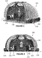
- FIGS. 1-5 are respectively a perspective view, a front view, a top view, a side view and a rear view of an immersive work station, according to an embodiment
- FIGS. 6-9 are respectively a perspective view, a top view, a front view and a side view of an immersive work station, according to another embodiment
- FIG. 10 is a top view illustrating image display in a simulator using a direct-projection screen, according to the prior art
- FIG. 11 is a top view illustrating image display in a simulator as should be seen by two pilots, according to the prior art
- FIG. 12 is a top view illustrating image display in a simulator using a collimating mirror, according to the prior art
- FIGS. 13-14 are a side view and a perspective view illustrating a flight simulator, according to the prior art.
- FIG. 15 is a picture illustrating image display in a simulator, according to the prior art.
- FIG. 16 is a top view illustrating image display in a simulator as seen by two pilots, according to an embodiment
- FIG. 17 is a picture illustrating image display in a simulator, according to an embodiment
- FIG. 18 is a side view illustrating a flight simulator, according to an embodiment.
- FIG. 19 is a screenshot of a background comprising a plurality of elements acting as cues for depth perception, according to an embodiment.
- a digital environment designed to increase the perceived depth of digital content comprising a plurality of digital objects
- an immersive environment comprising a plurality of digital objects
- the invention described here is a digital environment designed to provide very strong psychological cues for depth.
- This environment is designed to be displayed in an immersive environment (collimated display or immersive display such as the one described below), and to display a rendered image perceived to be 3D to the observer, without requiring headwear or eye/gaze tracking which would otherwise be helpful to provide physiological cues for depth perception but which are not used with collimated displays or immersive displays.
- Such a digital scene can create additional opportunities for display in immersive environments.
- an immersive environment can be created that displays scenes that provide very strong psychological depth cues to the observer together with physiological cues that are only approximately consistent with the scene. The result is a scene that is perceived to be three dimensional to the observer without the need for headwear of eye/gaze/head tracking.
- Physiological cues involve binocular cues, i.e., cues perceived by having the two eyes detect different things or act differently.
- Accommodation is an example of a monocular cue which is also physiological, since it involves contracting the lens of the eyes for real objects seen at a small distance, such as less than 2 meters.
- Other monocular cues are mostly psychological, as they involve brain perception (which can be “tricked” by presenting adequate images to the eyes) instead of physiological changes in the eyes (e.g., differential eye muscle contraction, lens contraction).
- the digital scene may include computer-generated media content (e.g., video game, animation, etc.) or may also include the environment in which the user interacts with the system, i.e., the graphical user interface (GUI) of the operating system (OS).
- GUI graphical user interface
- the digital scene may include an application which involves GUI elements such as boxes, windows, panels, buttons and the like, i.e., selectable elements appearing on the display and with which the user is expected to interact.
- GUI elements such as boxes, windows, panels, buttons and the like, i.e., selectable elements appearing on the display and with which the user is expected to interact.
- a web browser would be a good example, or any other application having a menu, windows, panels or buttons, or any application presenting objects in front of a background.
- standard selectable elements such as windows, boxes, panels, etc., meant to be used on a 2D operating system could be replaced with the same type of elements with a three-dimensional shape instead, or objects such as doors, windows, or portals placed to appear in an immersive 3D environment.
- these elements would benefit from a perception of depth when being displayed.
- collimated displays and immersive displays do not provide distinct screens or optical systems to isolate what is viewed by each eye, physiological cues for depth perception are significantly weaker than for VR headsets, for example, i.e., the left eye and the right eye are not presented different images as in a VR headset or in a 3D movie display involving glasses.
- Psychological cues for depth should thus be provided when the elements are being displayed in collimated displays and other immersive displays.
- a digital environment (such as the GUI of an operating system, or the GUI of an application to be displayed in an immersive display, or any other graphical user interface) with digital content designed to provide psychological cues for depth that are as strong as possible (see following picture) can include, without limitation: occlusion, depth form motion, kinetic depth effect, familiar size, linear perspective, texture gradient, aerial perspective, relative size, defocus blur, and/or elevation.
- Occlusion is an effect by which the brain identifies that one object partially hides another object and that, therefore, the object which partially hides the other one is located closer, and the one which is partially occluded is located farther.
- reproducing this “occlusion” effect comprises adding objects to the GUI that will occlude each other, and ensuring that the order by which each occlusion of an object with respect to another one reflect their intended depth.
- Superimposition of a more proximal object over a more distal object, as viewed from the viewer's point of view provides an impression that the distal object is further away than the proximal object, as intended.
- Depth from Motion is the effect by which depth can be assessed by the brain when an object has a motion with a significant component in the radial direction from the viewer. By moving, the object will become larger or smaller in the field of view of that person, thus assessing depth.
- reproducing this “depth from motion” effect involves making objects move along grid lines, or providing bright spots moving along grid lines, especially grid lines extending radially from the viewer or from a point near the viewer, such that the movement artificially given to the object in the user interface has a detectable component in a radial direction from the viewer.
- the kinetic depth effect refers to the eventual perception of depth of a three-dimensional object viewed in two dimensions, which arises after a period of time during which the object rotates, allowing the viewer to perceive depth and shape even though only a planar view of the object (e.g., its shadow) is being seen at a given instant.
- reproducing this “kinetic depth effect” involves placing objects in an environment having walls, a ceiling and/or a floor, and rotating and/or moving floor and/or ceiling and/or walls with respect to objects, or rotating and/or moving objects with respect to floor and/or ceiling and/or walls. This movement gives a perception of where an object is located with respect to its surrounding.
- the “Familiar Size” effect occurs when the brain identifies objects having an absolute size that is already known and determines that their size in the environment should be as expected, thus assessing their distance depending on the angular size of the perceived object.
- reproducing this “Familiar Size” effect involves providing, in the digital environment, objects having a size that is already known outside the digital environment because they are objects with standard sizes with which any viewer will be familiar. These objects act as size-reference objects. For example, objects with standard sizes such as cars or doors can be included in the GUI to provide a reference or standard by which other objects can be gauged.
- Linear Perspective is an effect by which portions of an objects extending on a distance from the viewer appear narrower with distance, e.g., standing in the middle of the road and looking ahead, the road will extend away from the viewer and will seem to get narrower with the distance.
- reproducing this “linear perspective” involves placing objects along grid lines that represent their location in space. The grid lines do not need to be seen by the viewer.
- the linear perspective is created by placing objects along invisible grid lines, adjusting their size depending and the distance/depth that needs to be perceived for each object, and this linear perspective gives depth perception.
- Texture gradient involves adding lighting and/or shadowing onto a surface of a displayed object to provide an impression of where the objects is located with respect to a light source or, by providing differentiated lighting/shadowing on different objects, therefore reproducing a contextual environment as would exist in real life, to give the impression that these different objects are not located at the same place.
- Aerial perspective refers the perception that distant objects are blurred, and their color saturation is reduced. Their contours are less sharp than for closer objects, and color is less saturated.
- reproducing this “aerial perspective” effect in a computer-generated user interface involves blurring distant objects so that they appear to be further away from the viewer (since real-life distant objects are also blurred by the distance).
- Color tinting for distant objects may also be provided.
- blurring and/or tinting are very slight so that they do not appear to be exaggerated. The effect is thus detectable but not plainly apparent.
- the “relative size” effect occurs if a plurality of identical objects in the environment do not appear with the same size from the viewer's perspective but it is nonetheless clear that they should. Then, the viewer will perceive that the objects are located at different distances and will thus perceive depth.
- this technique is implemented by providing in the environment a plurality of objects of equal size (such as a plurality of identical objects) located throughout the environment, and adjusting the size of each of these identical objects to reflect their respective distance from the viewer in the digital environment.
- Defocus Blur is a technique that involves blurring or defocusing/focusing different depths of environment. This strategy adds atmospheric distortion at large distances from the viewer, therefore reproducing a contextual environment as would exist in real life, so that the viewer can perceive depth of planes places at different distances.
- Elevation is a technique which can be implemented in an embodiment of the invention and which involves rendering an environment (i.e., background) with an explicit representation of the horizon (e.g., a line) roughly centered in the image.
- a vanishing point can be used instead of a horizon or in addition thereto.
- some of the lines in the object rendering may be expected to be parallel (e.g., edges of a building) but do not appear parallel in the rendering due to the perspective; when these lines are extended, they eventually intersect, thus defining the vanishing point.
- the application running and outputted on the immersive display comprises a type of background commonly known as a skybox.
- a skybox refers to a background comprising a panoramic image represented a sky or any distant background having a texture (not a uniform monochrome background).
- the skybox is normally split into six panels or “textures”, each one representing a direction (up, down, left, right, forward and backward).
- at least one of the strategies mentioned above is implemented in the skybox to provide a reference to the viewer within the skybox which makes up the background of the application.
- the near clipping plane (or more generally a near clipping surface) can be set at a particular location in order to enhance immersion.
- Clipping refers to the selection of only a region (volume defined by border planes) of a 3D environment to be rendered graphically.
- the near clipping plane is the plane which borders this region and which is the closest to the point of view of the rendering.
- the observer is located at a given distance D from the image surface or from the display screen.
- the near clipping plane is set at this same distance D (e.g., by the operating system which knows the display parameters including the distance D).
- FIGS. 1-9 illustrate a workstation having an immersive display.
- FIG. 19 illustrates a plurality of objects which are displayed on a grid using a variety of the techniques exposed above.
- an immersive work station 200 which, among other things, uses a designed virtual surface 240 to create an immersive display, in which such techniques can be advantageously implemented.
- This immersive display uses the equipment of a collimated display to achieve a more immersive environment by using the designed virtual surface and can benefit from the various techniques of psychological cues for depth perception when displaying objects such as the GUI of the operating system running on the computer system which feeds the immersive display, when using a web browser, when browsing between menus, windows, panels and buttons or when viewing a computer-generated or computer-edited animation involving a plurality of objects.
- a work station is an environment in which a user can view content, and possibly interact with it.
- the display comprises a curved, mirrored surface 240 and a display screen 230 together designed to create an immersive display system using collimated or nearly-collimated light, which is projected taking into account psychological depth cues (especially those described above) that must be provided in the final virtual image.
- the projector 220 is thus controlled according to a method described further below to create virtual images having a more realistic depth when viewed by the user in the immersive station comprising the immersive display, and further controlled by a computer system to control how digital objects are placed within a digital environment to enhance psychological depth cues in the image rendering to the viewer in the virtual image seen by the viewer.
- a structure or frame can be used to hold the mirrored surface 240 in place, and optionally serve as a support to hold speakers of the sound systems which are physically located around the user of the workstation to provide immersive audio contents consistent with the immersive image rendering of the display.
- the immersive display described herein places the display screen closer to the mirror than these systems, at a location sufficiently close to the mirror to present an image to the viewer at closer distances (i.e., the virtual image is produced at a finite and realistic distance, close to the mirror), more representative of typical every-day viewing.
- This configuration makes it possible to achieve an immersive display for applications where objects need to be shown closer to the observer than in conventional flight simulator displays.
- collimated display where the display screen is located, with respect to the mirror, closer than the distance that would produce collimated light when reflecting from the mirror, is an increase in the area the observer can view the image with acceptable quality. This area is often referred to as the eyebox of the display.
- These collimated displays have the added benefit of having two or more times the eyebox size of conventional collimated displays.
- the screen mirror needs to be redesigned from a spherical shape to a non-spherical shape. This requires tools for designing this shape that should be based on the method described further below.
- the display system comprises the components needed to create an optimal sense of immersion by the user for a given application, thanks to a large field-of-view display greater than 30° in at least one direction (horizontal and/or vertical) provided by a mirror close to the user, and to the collimated display system designed to optimize sense of depth using algorithms of virtual image creation described further below.
- a mirror too close from the viewer provides a virtual image with poor depth sensation, complicates the optics, and degrades the image quality.
- the image should be rendered to maximize immersion.
- the image displayed to the viewer is presented with the correct perspective.
- the perspective of the rendered image matches the perspective one would see while looking out windows of the same size as the mirrors and at the same location. This maximizes the realism of the displayed image. This is because nearby objects are correctly imaged in a finite-distance virtual image.
- frustum correction to convert the commonly used clipped pyramid in computer graphics rendering (the viewing frustum) to a spherical segment adapted to the shape of the screen mirror (i.e., the virtual surface).
- spherical rendering or other software techniques to render images with the correct perspective can be performed.
- a three-dimensional (3D) sound system comprising speakers, headphones, or any other sound system that generates sound anchored to a specific location in 3D world around the user.
- Sound is tethered to locations in the digital world, and played with a volume, quality, and possibly in a directional manner that complements the rendered image by mimicking real-life sound cues consistently with the images being viewed in the immersive displays.
- a system for user interaction with the digital environment in which the user is immersed should allow manipulation of digital content and navigation through the content presented on the screen, where the presentation of the content is controlled by the operating system. For example, voice commands (using a microphone) can be implemented.
- a control board in front of the user, with buttons and/or touch commands, can be provided to interact with the operating system.
- a movement tracking system comprising cameras or infrared detectors, can be used to track body parts of the user (e.g., their hands) intended to have a meaning according to predetermined rules within the work station. Browsing through the digital content and performing manipulations should be intuitive. Pointing to a specific element in the displayed digital content with a finger, as detected by cameras or infrared detectors, to select a given element in the content presented to the user is an example of an intuitive operation performed on the content.
- imaging an object at infinity is not always desirable, as the simulation may include objects that would normally be close to the viewer.
- the image therefore does not appear realistically.
- the slight angular difference of a virtual image between both eyes of a viewer serves as a cue interpreted by the viewer to determine the distance of what is being seen. The lack of this cue can be confusing and does not provide adequate realism.
- collimated displays In collimated displays, a projector first projects an image onto a surface acting as an object that must be mirrored to form a virtual image of this object that will be viewed by the user. The objects are thus viewed “through” a mirrored surface as the virtual image is located behind the mirror. Collimated displays provide a virtual image at infinity, first because flight simulators often image objects that are supposed to be located far away, and secondly because Gaussian optics is adapted to approximating the virtual image at infinity. However, it is advantageous and sometimes necessary to determine more precisely the location of this image, however there remains a lack of techniques suitable for this purpose.
- the virtual image of an object viewed through a lens or reflecting from a mirror is commonly portrayed as if it is independent of the viewer's position, though in fact this is only true when the object is viewed close to the optical axis of the lens or mirror.
- the location of a virtual image viewed by a human observer is a psychological phenomenon, which depends on several depth cues that sometimes conflict. This can lead to surprising results, including the virtual image location changing when a viewer tilts her head.
- the human brain uses a wide variety of depth cues to determine the depth of an object. These cues consist of both physiological and psychological cues.
- the depth cues affected by a mirror's and object's shape are the physiological cues, including accommodation, convergence, and binocular and monocular parallax.
- the accommodation cue for depth arises from the need to bend or relax the lens of the eye in order to see an image in focus.
- the amount of constriction for the lens that is necessary to bring the image into focus gives a cue to the rough distance of the image from the eye.
- This physiological, monocular cue for depth is known as accommodation, though it is the cue relied on least by the human brain to infer depth.
- Binocular parallax arises from the brain seeing an image from both eyes at once, while monocular parallax comes from the brain seeing an image from different locations at different times. In both cases, the brain is able to infer depth based on the relative movement of objects viewed from the two or more different locations. Binocular parallax is an effective depth cue up to a distance of about 20 m. The strength of the monocular parallax cue depends on the amount of movement of the head, with movements of only a few mm sufficient to contribute to perceived depth.
- the method for determining a virtual image has two bases: first, using techniques valid where standard Gaussian techniques are not, and second, simplifying the problem of the many different, conflicting depth cues used by a human observer into a simpler, resolvable problem.
- the problem is simplified by determining the virtual image of an object by determining only the horizontal parallax cue, which is for movement of the observer's head along a direction parallel to the plane defined by the floor or the ground or any other reference element.
- Human observers are far more likely to move in directions parallel to the plane they stand on than they are to move up and down vertically, or to move their head forward and backward, so this result is the most important for most applications.
- this cue is equivalent to the stereoscopic parallax and convergence cues. Cues such as accommodation are ignored as they do not significantly contribute to perceived depth at distances greater than 2 m, and parallax cues for movement in different directions is ignored since human observers are much less likely to move in these directions. This results in depth cues that are in agreement with one another, and hence a single virtual image can now be determined.
- This method for determining a virtual image surface was designed to be practical and convenient for designing an object screen or mirrored surface to create a desired virtual surface for a human observer at a known location, for example in a work station, a flight simulator, a home theater, or the like. It can further be used when displaying the digital scene as discussed above, such as computer-generated media content (e.g., video game, animation, etc.), the graphical user interface (GUI) of the operating system (OS), an application which involves boxes, windows, panels, buttons and the like, a web browser, or any application presenting objects in front of a background, for example.
- computer-generated media content e.g., video game, animation, etc.
- GUI graphical user interface
- OS operating system
- an application which involves boxes, windows, panels, buttons and the like
- a web browser or any application presenting objects in front of a background, for example.
- the method can be used to determine the location of an object displayed on a display screen that, when viewed reflecting on a curved mirror, produces a virtual image that provides a parallax and/or stereoscopic cues, which optimizes the sense of depth giving greater realism to the display. This can be used to achieve a greater sense of visual immersion in the context of the immersive display, as contemplated.
- the display would thus include a projector and intermediate screen, where the projector is controlled by a processor executing a program for projecting each portion of an image at a specific location on the intermediate screen to produce the virtual images as contemplated by the method of determination described above.
- the method can also be used to determine the shape of the curved mirror and/or the shape of the display screen ensuring that, when an object is viewed reflecting on a curved mirror, produces a virtual image of the object that provides a parallax and/or stereoscopic cues.
- the display would thus include such a curved mirror.
- This method can be extended to work with mirror shapes other than just hemispheres, as well as with lenses that cannot be accurately modeled using conventional techniques. Therefore, even though the equations developed above are to be used in reflection, a similar set of equations can be developed for refraction to account for parallax or stereoscopic cues when an image is viewed through a lens. Either the lens, the location of the object or the shape of the display screen on which the object is displayed can be determined to ensure the image viewed by the user (e.g., virtual image for a divergent lens) is produced to provide parallax or stereoscopic cues.
- the lens, the location of the object or the shape of the display screen on which the object is displayed can be determined to ensure the image viewed by the user (e.g., virtual image for a divergent lens) is produced to provide parallax or stereoscopic cues.
- the method described above is used to control the location of a projected image portion by a projector which projects onto a display screen which generates a specific virtual image when the display screen is viewed reflecting from a mirror.
- the display screen can be a LCD screen, a rear projection screen, a front projection screen or any other display screen suitable to be viewed reflecting from a curved mirror such that the final image is eventually rendered by the curved mirror.
- a state-of-the-art collimated display is shown, exemplarily embodied as a flight simulator.
- the cockpit is physically close to the pilot trainee.
- the cross-cockpit is the virtual image, reflected by the collimating mirror, of an image produced on a projection screen by projects.
- the virtual image is located at infinity.
- a flight simulator 100 having a collimated display for implementing the method is shown in FIG. 18 .
- the pilot trainee is installed in the cockpit 110 and views the virtual images as reflected by the mirror 140 from the object, which is the projection screen or display screen 130 .
- the object is created by having the projectors 120 illuminating the display screen 130 .
- a work station can be provided with the collimated display producing virtual images with depth cues giving more realism to the visual contents being viewed by the user.
- the method described above can provide much larger convergence and/or divergence tolerances for a collimated display.
- convergence and divergence when an observer looks at an object, they direct their two eyes towards it. The angle between the direction vectors of their two eyes is known as the convergence angle. When their two eyes are directed away from one another, the angle between them is the divergence angle. When the angle is divergent, the situation is painful for the brain, and this situation is rarely encountered unless the observer looks at a curved mirror. When looking at something close to the observer, the convergence angle between the eyes is large, and when looking at an object very far away, the convergence angle is almost zero.
- the convergence angle is close to zero because the virtual surface is at a long distance in front of the observer. If the observer moves away from the designed eye point, however, the image can distort, and so the user will either have to converge their eyes more to see the image clearly or, more commonly, need to diverge their eyes to see an image, which makes the display very painful to look at. This can happen when an observer moves as little as 20 cm from the eye point. If the virtual surface of a collimated display is brought closer, however, the convergence angle is much higher at the eye point. If the observer moves 20 cm from the eye point in this case, the convergence angle will drop, but will not result in divergence.
- the method described above ensures that the virtual image provides a parallax and/or stereoscopic depth cues, may allow for locating the curved mirror closer to the user and thus improves the tolerance on convergence/divergence experienced by the binocular observer moving horizontally.
- Embodiments of a work station 200 are shown in FIGS. 1-9 .
- the display screen 230 and/or the mirror(s) 240 have shapes defined by the equations above.
- the projectors are controlled by a program defined by instructions executed on a computer system in communication with the projectors to project an intermediate image on the display screens 230 which in turn are the object forming the virtual image when reflected by the mirror(s) 240 .
- the distance between the display screens 230 and the mirror(s) 240 is substantially smaller than the distance that would produce completely collimated light. This allows for a virtual image produced at a finite location when viewed by the user of the work station 200 .
- a table or control board 270 can be provided in front of the user.
- Other elements such as a sound system or control commands as discussed above, can be provided.
- the overall result is an environment in which objects that should be close to the user in the environment appear effectively closer, with a right sense of depth thanks to the depth cues provided by the shape of the mirror(s) 240 , or the shape of the images projected by the projectors 220 on the display screens 230 taking into account the depth cues.
- the work station 200 described above can thus be used to implement a digital environment designed to maximize or increase depth sensation.
- the work station comprises a computer system. It comprises a memory for storing instructions and data, and a processor for executing the instructions.
- the computer system is in communication with the projectors 220 .
- the computer system generates the signal for the projection and display, and can act on what is projected.
- the computer system when instructing the projectors of the work station 200 (or of a collimated display) implements at least of the following elements:
- displaying the plurality of digital objects within the digital environment is controlled by the computer system for setting at least one of a near clipping plane and a far clipping plane of the image rendering to be equal to a characteristic distance in the immersive environment.
- the characteristic distance comprises one of the following distances: a distance from an observer to display screen; a distance from the observer to mirrored surface; a distance from the observer to the virtual image itself; a distance from the observer to a lens or any other refracting element, or from the observer to any other optical element which contributes in producing the virtual image. Doing this ensures consistency in image creation and produces an appropriate cue for the observer.
- These techniques can be implemented such that digital objects are placed within a digital environment to eventually provide an image rendering with enhanced depth perception using these psychological cues.
- the implementation can be done, for example, within an operating system of the computer system designed to be used in an immersive environment, or in a video or computer-generated or computer-edited animation designed to be displayed in an immersive environment, or in an application installed or used within the computer system and having a background, or “skybox”, or in an image or background designed to be displayed in an immersive display environment, or in a web browser/web portal/web environment to be displayed in an immersive environment and used on the computer system which implements at least one of the techniques mentioned above.
- the method described above can be applied advantageously on immersive displays involving mirrors as described above. However, it could also apply to immersive displays that do not involve mirrors, such as direct-projection displays or even VR head-mounted displays (HMDs). In these mirror-less displays, the rendered fields of view (those rendered in the environment on the display) match the fields of view subtended by the display to the viewer. This is the reason why the method described above can apply to direct-projection displays and VR HMDs.
Landscapes
- Engineering & Computer Science (AREA)
- Physics & Mathematics (AREA)
- General Physics & Mathematics (AREA)
- Theoretical Computer Science (AREA)
- Computer Graphics (AREA)
- Signal Processing (AREA)
- Multimedia (AREA)
- Computer Hardware Design (AREA)
- Optics & Photonics (AREA)
- Architecture (AREA)
- General Engineering & Computer Science (AREA)
- Software Systems (AREA)
- Geometry (AREA)
- Processing Or Creating Images (AREA)
- Testing, Inspecting, Measuring Of Stereoscopic Televisions And Televisions (AREA)
Abstract
Description
-
- Collimated displays—projected image at >60 ft.;
- Front or rear projection-based display systems (no mirrors involved);
- Head-mounted displays for virtual reality.
-
- displaying a plurality of objects within an immersive environment, to provide to a viewer an image rendering that is immersive; and
- by a computer system:
- controlling an image rendering of the immersive environment; and
- controlling a size and a location of each one of the plurality of objects,
to provide a monocular psychological depth cue to the viewer for each one of the plurality of objects.
-
- using a computer system to locate a plurality of digital objects within a digital environment on a display screen of an immersive display distant from an observer at a distance D to provide an image rendering that is immersive;
wherein displaying the plurality of digital objects within the digital environment is controlled by the computer system for setting at least one of a near clipping plane and a far clipping plane of the image rendering to be equal to a characteristic distance in the immersive environment defined from an observer to an optical element contributing to producing the virtual image.
- using a computer system to locate a plurality of digital objects within a digital environment on a display screen of an immersive display distant from an observer at a distance D to provide an image rendering that is immersive;
-
- the digital objects are placed in an environment consisting of parallel lines extending along reference elements;
- the digital objects, or a lighting artifact thereof, are shown moving within the digital environment at approximately constant speeds; and
- a substantially constant rotation is applied between the objects and reference elements of the environment.
-
- lighting or shadowing gradients are provided onto a surface of the objects depending on a respective location thereof in the environment;
- objects are blurred or tinted depending on the respective distance from the viewer; and
- at least one of a horizon and a vanishing point is provided within rendered image.
-
- providing an operating system on the computer system that places a plurality of digital objects within a digital environment on a display screen of the immersive display distant from an observer at a distance D to provide an image rendering that is immersive;
wherein displaying the plurality of digital objects within the digital environment is controlled by the operating system on the computer system to implement a monocular psychological depth cue to the observer for each one of the plurality of objects, comprising setting at least one of a near clipping plane and a far clipping plane of the image rendering to be equal to a characteristic distance in the immersive environment defined from the observer.
- providing an operating system on the computer system that places a plurality of digital objects within a digital environment on a display screen of the immersive display distant from an observer at a distance D to provide an image rendering that is immersive;
-
- the digital objects are placed in an environment consisting of parallel lines extending along reference elements;
- the digital objects, or a lighting artifact thereof, are shown moving within the digital environment at approximately constant speeds;
- a substantially constant rotation is applied between the objects and reference elements of the environment; and
- the image rendering comprises setting a near clipping plane or surface to be equal to the distance D from the observer.
-
- lighting or shadowing gradients are provided onto a surface of the objects depending on a respective location thereof in the environment;
- objects are blurred or tinted depending on the respective distance from the viewer; and
- at least one of a horizon and a vanishing point is provided within rendered image.
-
- 1) Determining the location of the observer that will be viewing the virtual image and the direction the observer is facing (in order to determine the interocular vector R);
- 2) Determining the shape and location of the mirror in space;
- 3) Defining the desired virtual image/surface, and consequently the image distance from the observer to the desired surface.
- 4) Determining the object distance from the mirror to the projection screen or display that will achieve this desired virtual image, where the projection screen or display is located at a distance from the mirror which is smaller than the focal length of the mirror.
- 5) Controlling the image projected by the
projectors 120 to get the targeted projected image on thedisplay screen 130.
-
- Parallel lines extending along a planar or non-planar floors, walls, ceilings, or obstacles or any other reference element;
- Objects placed so that they will occlude each other and portions of the environment;
- Objects or lighting artifacts moving through environment at approximately constant speeds;
- Approximately constantly rotating objects, floors, ceilings, or walls;
- Placing objects of a size that is familiar to the observer, such as doors or automobiles, etc.;
- Lighting sources in digital environment designed to creating texture gradients and shadowing;
- Blurring or color tinting of distant objects, or effects such as atmospheric distortion for objects at large distances;
- Using many objects of equal size placed at different distances;
- Placing horizon and/or vanishing point within rendered image;
- Setting the near clipping plane or surface of the rendered image to be equal to the distance from the observer to the display screen or image surfaces.
Claims (19)
Priority Applications (1)
| Application Number | Priority Date | Filing Date | Title |
|---|---|---|---|
| US16/238,568 US11170563B2 (en) | 2018-01-04 | 2019-01-03 | Immersive environment with digital environment to enhance depth sensation |
Applications Claiming Priority (2)
| Application Number | Priority Date | Filing Date | Title |
|---|---|---|---|
| US201862613604P | 2018-01-04 | 2018-01-04 | |
| US16/238,568 US11170563B2 (en) | 2018-01-04 | 2019-01-03 | Immersive environment with digital environment to enhance depth sensation |
Publications (2)
| Publication Number | Publication Date |
|---|---|
| US20190206118A1 US20190206118A1 (en) | 2019-07-04 |
| US11170563B2 true US11170563B2 (en) | 2021-11-09 |
Family
ID=67057744
Family Applications (1)
| Application Number | Title | Priority Date | Filing Date |
|---|---|---|---|
| US16/238,568 Active 2039-01-18 US11170563B2 (en) | 2018-01-04 | 2019-01-03 | Immersive environment with digital environment to enhance depth sensation |
Country Status (2)
| Country | Link |
|---|---|
| US (1) | US11170563B2 (en) |
| CA (1) | CA3028794A1 (en) |
Families Citing this family (4)
| Publication number | Priority date | Publication date | Assignee | Title |
|---|---|---|---|---|
| US11189047B2 (en) * | 2019-03-11 | 2021-11-30 | Disney Enterprises, Inc. | Gaze based rendering for audience engagement |
| US11763517B1 (en) * | 2020-02-27 | 2023-09-19 | Apple Inc. | Method and device for visualizing sensory perception |
| CN112382152B (en) * | 2020-11-26 | 2023-03-21 | 中国人民解放军陆军军医大学第一附属医院 | Intelligent teaching auxiliary system |
| CN114758558B (en) * | 2022-04-27 | 2023-01-31 | 上海华模科技有限公司 | Flight simulator |
Citations (15)
| Publication number | Priority date | Publication date | Assignee | Title |
|---|---|---|---|---|
| US5880733A (en) * | 1996-04-30 | 1999-03-09 | Microsoft Corporation | Display system and method for displaying windows of an operating system to provide a three-dimensional workspace for a computer system |
| US6230116B1 (en) | 1997-10-02 | 2001-05-08 | Clockwise Technologies Ltd. | Apparatus and method for interacting with a simulated 3D interface to an operating system operative to control computer resources |
| US6597358B2 (en) | 1998-08-26 | 2003-07-22 | Intel Corporation | Method and apparatus for presenting two and three-dimensional computer applications within a 3D meta-visualization |
| US20050264857A1 (en) * | 2004-06-01 | 2005-12-01 | Vesely Michael A | Binaural horizontal perspective display |
| US7107549B2 (en) | 2001-05-11 | 2006-09-12 | 3Dna Corp. | Method and system for creating and distributing collaborative multi-user three-dimensional websites for a computer system (3D Net Architecture) |
| US20090066786A1 (en) * | 2004-05-10 | 2009-03-12 | Humaneyes Technologies Ltd. | Depth Illusion Digital Imaging |
| US20110075257A1 (en) * | 2009-09-14 | 2011-03-31 | The Arizona Board Of Regents On Behalf Of The University Of Arizona | 3-Dimensional electro-optical see-through displays |
| US20120287125A1 (en) * | 2010-02-01 | 2012-11-15 | Wuqiang Liu | Three-dimensional stereoscopic imaging method, system and imaging device |
| US20150035821A1 (en) * | 2013-08-01 | 2015-02-05 | Equldp Limited | Stereoscopic online web content creation and rendering |
| US20150254882A1 (en) * | 2014-03-06 | 2015-09-10 | Ram Industrial Design, Inc. | Wireless immersive experience capture and viewing |
| US20170105052A1 (en) * | 2015-10-09 | 2017-04-13 | Warner Bros. Entertainment Inc. | Cinematic mastering for virtual reality and augmented reality |
| WO2018161163A1 (en) | 2017-03-07 | 2018-09-13 | Jason Carl Radel | Method to control a virtual image in a display |
| US20180259903A1 (en) * | 2017-03-06 | 2018-09-13 | Paul Patrick Paige | Holographic-like imaging devices and systems |
| US20180300854A1 (en) * | 2015-01-23 | 2018-10-18 | Yandex Europe Ag | Method and electronic device for rendering a panorama image |
| US20180322685A1 (en) * | 2017-05-05 | 2018-11-08 | Via Alliance Semiconductor Co., Ltd. | Methods of compressing a texture image and image data processing system and methods of generating a 360 degree panoramic video thereof |
-
2019
- 2019-01-03 US US16/238,568 patent/US11170563B2/en active Active
- 2019-01-03 CA CA3028794A patent/CA3028794A1/en active Pending
Patent Citations (15)
| Publication number | Priority date | Publication date | Assignee | Title |
|---|---|---|---|---|
| US5880733A (en) * | 1996-04-30 | 1999-03-09 | Microsoft Corporation | Display system and method for displaying windows of an operating system to provide a three-dimensional workspace for a computer system |
| US6230116B1 (en) | 1997-10-02 | 2001-05-08 | Clockwise Technologies Ltd. | Apparatus and method for interacting with a simulated 3D interface to an operating system operative to control computer resources |
| US6597358B2 (en) | 1998-08-26 | 2003-07-22 | Intel Corporation | Method and apparatus for presenting two and three-dimensional computer applications within a 3D meta-visualization |
| US7107549B2 (en) | 2001-05-11 | 2006-09-12 | 3Dna Corp. | Method and system for creating and distributing collaborative multi-user three-dimensional websites for a computer system (3D Net Architecture) |
| US20090066786A1 (en) * | 2004-05-10 | 2009-03-12 | Humaneyes Technologies Ltd. | Depth Illusion Digital Imaging |
| US20050264857A1 (en) * | 2004-06-01 | 2005-12-01 | Vesely Michael A | Binaural horizontal perspective display |
| US20110075257A1 (en) * | 2009-09-14 | 2011-03-31 | The Arizona Board Of Regents On Behalf Of The University Of Arizona | 3-Dimensional electro-optical see-through displays |
| US20120287125A1 (en) * | 2010-02-01 | 2012-11-15 | Wuqiang Liu | Three-dimensional stereoscopic imaging method, system and imaging device |
| US20150035821A1 (en) * | 2013-08-01 | 2015-02-05 | Equldp Limited | Stereoscopic online web content creation and rendering |
| US20150254882A1 (en) * | 2014-03-06 | 2015-09-10 | Ram Industrial Design, Inc. | Wireless immersive experience capture and viewing |
| US20180300854A1 (en) * | 2015-01-23 | 2018-10-18 | Yandex Europe Ag | Method and electronic device for rendering a panorama image |
| US20170105052A1 (en) * | 2015-10-09 | 2017-04-13 | Warner Bros. Entertainment Inc. | Cinematic mastering for virtual reality and augmented reality |
| US20180259903A1 (en) * | 2017-03-06 | 2018-09-13 | Paul Patrick Paige | Holographic-like imaging devices and systems |
| WO2018161163A1 (en) | 2017-03-07 | 2018-09-13 | Jason Carl Radel | Method to control a virtual image in a display |
| US20180322685A1 (en) * | 2017-05-05 | 2018-11-08 | Via Alliance Semiconductor Co., Ltd. | Methods of compressing a texture image and image data processing system and methods of generating a 360 degree panoramic video thereof |
Also Published As
| Publication number | Publication date |
|---|---|
| CA3028794A1 (en) | 2019-07-04 |
| US20190206118A1 (en) | 2019-07-04 |
Similar Documents
| Publication | Publication Date | Title |
|---|---|---|
| US11170563B2 (en) | Immersive environment with digital environment to enhance depth sensation | |
| US10739936B2 (en) | Zero parallax drawing within a three dimensional display | |
| US20210065432A1 (en) | Method and system for generating an image of a subject in a scene | |
| US20160267720A1 (en) | Pleasant and Realistic Virtual/Augmented/Mixed Reality Experience | |
| CA3053004C (en) | Method to control a virtual image in a display | |
| US11277603B2 (en) | Head-mountable display system | |
| US20210283496A1 (en) | Realistic Virtual/Augmented/Mixed Reality Viewing and Interactions | |
| JP2019079552A (en) | Improvements in and relating to image making | |
| SG181708A1 (en) | A system and method for producing stereoscopic images | |
| WO2016118344A1 (en) | Fixed size augmented reality objects | |
| US20150304645A1 (en) | Enhancing the Coupled Zone of a Stereoscopic Display | |
| WO2021124920A1 (en) | Information processing device, information processing method, and recording medium | |
| US10523912B2 (en) | Displaying modified stereo visual content | |
| US11961194B2 (en) | Non-uniform stereo rendering | |
| US20240168545A1 (en) | Systems and Methods For Providing Observation Scenes Corresponding to Extended Reality (XR) Content | |
| CN111699460A (en) | Multi-view virtual reality user interface | |
| JP6198157B2 (en) | Program, recording medium, image processing apparatus, and image processing method | |
| JP2018112885A (en) | Program and image generation system |
Legal Events
| Date | Code | Title | Description |
|---|---|---|---|
| AS | Assignment |
Owner name: 8259402 CANADA INC., CANADA Free format text: ASSIGNMENT OF ASSIGNORS INTEREST;ASSIGNORS:RADEL, JASON CARL;PETRUZZIELLO, FERNANDO;REEL/FRAME:047886/0093 Effective date: 20180907 |
|
| FEPP | Fee payment procedure |
Free format text: ENTITY STATUS SET TO UNDISCOUNTED (ORIGINAL EVENT CODE: BIG.); ENTITY STATUS OF PATENT OWNER: SMALL ENTITY |
|
| FEPP | Fee payment procedure |
Free format text: ENTITY STATUS SET TO SMALL (ORIGINAL EVENT CODE: SMAL); ENTITY STATUS OF PATENT OWNER: SMALL ENTITY |
|
| STPP | Information on status: patent application and granting procedure in general |
Free format text: NON FINAL ACTION MAILED |
|
| STPP | Information on status: patent application and granting procedure in general |
Free format text: RESPONSE TO NON-FINAL OFFICE ACTION ENTERED AND FORWARDED TO EXAMINER |
|
| STPP | Information on status: patent application and granting procedure in general |
Free format text: ADVISORY ACTION MAILED |
|
| STPP | Information on status: patent application and granting procedure in general |
Free format text: DOCKETED NEW CASE - READY FOR EXAMINATION |
|
| STPP | Information on status: patent application and granting procedure in general |
Free format text: NON FINAL ACTION MAILED |
|
| STPP | Information on status: patent application and granting procedure in general |
Free format text: RESPONSE TO NON-FINAL OFFICE ACTION ENTERED AND FORWARDED TO EXAMINER |
|
| STPP | Information on status: patent application and granting procedure in general |
Free format text: NOTICE OF ALLOWANCE MAILED -- APPLICATION RECEIVED IN OFFICE OF PUBLICATIONS |
|
| STPP | Information on status: patent application and granting procedure in general |
Free format text: PUBLICATIONS -- ISSUE FEE PAYMENT VERIFIED |
|
| STCF | Information on status: patent grant |
Free format text: PATENTED CASE |