US11142131B2 - Modular roof rack system - Google Patents
Modular roof rack system Download PDFInfo
- Publication number
- US11142131B2 US11142131B2 US15/930,264 US202015930264A US11142131B2 US 11142131 B2 US11142131 B2 US 11142131B2 US 202015930264 A US202015930264 A US 202015930264A US 11142131 B2 US11142131 B2 US 11142131B2
- Authority
- US
- United States
- Prior art keywords
- modular
- platform
- rack system
- rail
- panels
- Prior art date
- Legal status (The legal status is an assumption and is not a legal conclusion. Google has not performed a legal analysis and makes no representation as to the accuracy of the status listed.)
- Active
Links
- 239000000758 substrate Substances 0.000 description 6
- 238000002955 isolation Methods 0.000 description 4
- 230000002787 reinforcement Effects 0.000 description 4
- 238000004378 air conditioning Methods 0.000 description 3
- 239000002184 metal Substances 0.000 description 3
- 229910052751 metal Inorganic materials 0.000 description 3
- 230000000712 assembly Effects 0.000 description 2
- 238000000429 assembly Methods 0.000 description 2
- 238000005452 bending Methods 0.000 description 2
- 230000007246 mechanism Effects 0.000 description 2
- 241001172812 Gallirallus rovianae Species 0.000 description 1
- PEDCQBHIVMGVHV-UHFFFAOYSA-N Glycerine Chemical compound OCC(O)CO PEDCQBHIVMGVHV-UHFFFAOYSA-N 0.000 description 1
- 230000008859 change Effects 0.000 description 1
- 239000000470 constituent Substances 0.000 description 1
- 238000010276 construction Methods 0.000 description 1
- 238000009826 distribution Methods 0.000 description 1
- 230000000694 effects Effects 0.000 description 1
- 238000001125 extrusion Methods 0.000 description 1
- 239000000463 material Substances 0.000 description 1
- 238000000034 method Methods 0.000 description 1
- 238000012986 modification Methods 0.000 description 1
- 230000004048 modification Effects 0.000 description 1
- 230000000149 penetrating effect Effects 0.000 description 1
- 230000008569 process Effects 0.000 description 1
- 230000000284 resting effect Effects 0.000 description 1
- 230000007704 transition Effects 0.000 description 1
- 238000004078 waterproofing Methods 0.000 description 1
Images


Classifications
-
- B—PERFORMING OPERATIONS; TRANSPORTING
- B60—VEHICLES IN GENERAL
- B60R—VEHICLES, VEHICLE FITTINGS, OR VEHICLE PARTS, NOT OTHERWISE PROVIDED FOR
- B60R9/00—Supplementary fittings on vehicle exterior for carrying loads, e.g. luggage, sports gear or the like
- B60R9/04—Carriers associated with vehicle roof
- B60R9/045—Carriers being adjustable or transformable, e.g. expansible, collapsible
Definitions
- This disclosure generally relates to cargo capacity, and, more particularly, to a modular roof rack system for vehicles.
- Vehicles such as vans, sport utility vehicles (SUVs), and other recreational and utility vehicles, provide versatility in a variety of applications. These applications can range from recreational activities (e.g., weekend trips) to use as a dwelling for extended periods of time, and are often associated with transporting cargo and/or accessories. For example, a person might use a roof rack to secure miscellaneous tools and equipment.
- recreational activities e.g., weekend trips
- SUVs sport utility vehicles
- the modular roof rack system comprises: a plurality of panels configured to be joined together in a same plane to form a platform with a flat top surface; and a plurality of rails configured to be joined together to form a modular frame surrounding the platform and extending above the top surface of the platform.
- the platform may comprise at least one opening through the platform and configured to accommodate a feature extending up from the roof of the vehicle.
- the platform may comprise a panel having the at least one opening in it.
- the at least one opening may be formed as a space between two separate ones of the plurality of panels, including as a space in a middle of four separate ones of the plurality of panels.
- At least a portion of the platform may be continuous from a first side of the platform to a second side of the platform that is opposite the first side, and at least a portion of the platform may be continuous from a third side of the platform to a fourth side of the platform that is opposite the third side.
- the plurality of panels may comprise a first panel having a first shape, and a second panel having a second shape that is different than the first shape.
- the plurality of rails may comprise a front rail, a rear rail, and two side rails extending between the front rail and the rear rail.
- Each of the two side rails may comprise a plurality of modular segments configured to be joined together linearly to form the respective side rail.
- the front rail may comprise an angled air dam.
- a portion of each of the two side rails that extends above the top surface of the platform may be angled inwards towards a center of the modular frame.
- Each portion of each of the two side rails that extends above the top surface of the platform may comprise a plurality of longitudinal slots.
- the modular rack system may further comprise a light bar configured to be attached to a front surface of the front rail, wherein, when the modular rack system is mounted on the roof of the vehicle, the light bar extends below the plane of the platform.
- the modular rack system may further comprise: a plurality of studded inserts, wherein each of the plurality of studded inserts is configured to slide into a rail on the roof of the vehicle; and a plurality of mounting brackets, wherein each of the plurality of mounting brackets is configured to be attached to a bottom surface of either of the two side rails, such that the mounting bracket extends downward from the side rail to which it is attached, and wherein each of the plurality of mounting brackets is configured to attach to one of the plurality of studded inserts.
- the platform may be configured to be joined to the modular frame and not to the roof of the vehicle, so as to only be fixed to the roof of the vehicle indirectly via attachment to the modular frame.
- Each of the plurality of panels may comprise a top portion and four side portions extending orthogonally downward from the top portion.
- Each of the four side portions of each of the plurality of panels may comprise one or more apertures configured to align with one or more corresponding apertures in either another one of the plurality of panels or one of the plurality of rails.
- Each of at least two of the four side portions may be tapered, such that a width of the side portion closer to the top portion is greater than a width of the side portion farther from the top portion.
- the modular frame may comprise a plurality of apertures configured to align with a plurality of apertures in one or more accessories configured to be attached to the modular frame.
- the modular rack system may further comprise the one or more accessories, wherein the one or more accessories comprise one or more of an awning mount, a boat roller, or a crossbar.
- FIG. 1A-1D illustrate top perspective views of different configurations of a modular rack system, according to an embodiment
- FIGS. 2A and 2B illustrate bottom views of different configurations of a modular rack system, according to an embodiment
- FIG. 3 illustrates a panel of a modular rack system, according to an embodiment
- FIGS. 4A-4E illustrate a manner in which panels may be joined together, according to an embodiment
- FIG. 5 illustrates a manner in which panels may be joined together, according to an alternative embodiment
- FIGS. 6A and 6B illustrate a manner in which panels may be joined together, according to an alternative embodiment
- FIGS. 7A-7E illustrate a manner in which segments of a rail may be joined together, according to an embodiment
- FIGS. 8A and 8B illustrate a manner in which segments of a rail may be joined together, according to an alternative embodiment
- FIGS. 9A and 9B illustrate a manner in which segments of a rail may be joined together, according to an alternative embodiment
- FIGS. 10A and 10B illustrate views of a front rail, according to an embodiment
- FIGS. 11A and 11B illustrate views of a rear rail, according to an embodiment
- FIGS. 12A and 12B illustrate a manner in which side and front rails may be joined, according to an embodiment
- FIGS. 13A-13C illustrate a manner in which side and rear rails may be joined, according to an embodiment
- FIGS. 14A-14C illustrate a manner in which panels and side rails may be joined, according to an embodiment
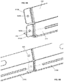
- FIGS. 15A-15D illustrate a manner in which a front rail, side rails, and a platform may be joined, according to an embodiment
- FIGS. 16A-16E illustrate a studded insert to be installed within rails on the roof of vehicle, according to an embodiment
- FIGS. 17A-17C illustrate a mounting bracket, according to an embodiment
- FIGS. 18A-18D illustrate a mounting bracket, according to an alternative embodiment
- FIGS. 19A-19E illustrate a mounting bracket, according to an alternative embodiment
- FIGS. 20A-20G illustrate top views of a plurality of different possible configurations of a modular rack system, according to embodiments
- FIGS. 21A-21F illustrate awning brackets used to form an awning mount on a modular rack system, according to an embodiment
- FIGS. 22A-22C illustrate a boat roller that may be mounted to a modular rack system, according to an embodiment
- FIGS. 23A and 23B illustrate a crossbar that may be mounted to a modular rack system, according to an embodiment
- FIGS. 24A-24C illustrate a crossbar that may be mounted to a modular rack system, according to an alternative embodiment
- FIGS. 25A-25D illustrate a light bar, integrated into a modular rack system, according to an embodiment.
- Embodiments are disclosed of a modular rack system that is designed for use with a vehicle (e.g., a van, such as the Mercedes SprinterTM, a minivan, an SUV, a recreational vehicle (RV), etc.).
- the modular rack system can be an after-market system that is installed after the vehicle has been purchased from a manufacturer or dealer.
- the modular rack system may be configured to attach to a roof of the vehicle to provide a platform, for example, for equipment and/or accessories.
- the modular rack system comprises panels and rails.
- the panels can be interchanged to form openings to accommodate pre-installed accessories, such as roof vents.
- Each panel may connect with surrounding panels and be secured through fasteners, such as nuts and bolts, screws, or interlocking connections, to form a flat substantially continuous platform.
- Panels can be added to or removed from the modular rack system to create different panel configurations that accommodate various vehicle sizes (e.g., varying wheelbases, body lengths, roof types, etc.) and may comprise openings to accommodate features on the roof of the vehicle (e.g., vents for attic fans and/or air-conditioning units, etc.).
- the rails can be lengthened or shortened to accommodate the different panel configurations by adding or removing rail portions or by swapping in or out rail portions of different lengths.
- accessories may be installed on the rails.
- FIG. 1A illustrates a modular rack system 100 , attached to a vehicle V, according to an embodiment.
- Modular rack system 100 can be mounted on the roof of vehicle V.
- modular rack system 100 comprises a modular frame 110 and a platform 120 comprising a plurality of connected panels 122 .
- Modular frame 110 may comprise first and second side rails 112 A and 112 B, a front rail 114 , and a rear rail 116 .
- each rail 112 , 114 , and 116 comprises one or more modular segments.
- the modular segments may be arranged linearly, and adjacent modular segments may be connected by rail brackets.
- First side rail 112 A and second side rail 112 B may be mirror images of each other. Thus, any features described with respect to one side rail 112 may also apply to the other side rail 112 .
- Modular rack system 100 may be affixed to the roof of vehicle V via mounting brackets that couple modular frame 110 to vehicle V.
- mounting brackets may be connected between each of side rails 112 and vehicle V to affix each side rail 112 to vehicle V.
- the mounting brackets may be connected to slidable inserts within a rail on the roof of vehicle V so that the length of side rails 112 can be easily adjusted (e.g., by adding, removing, or replacing modular segments of side rails 112 ), for example, to accommodate the particular wheel base of vehicle V, as described in greater detail elsewhere herein.
- one or more mounting brackets may be connected between front rail 114 and vehicle V and/or between rear rail 116 and vehicle V.
- a plurality of panels 122 are positioned and connected together to form a flat continuous platform 120 within modular frame 110 .
- each panel 122 extends from first side rail 112 A to second side rail 112 B.
- a front panel 122 A is positioned adjacent to front rail 114
- a rear panel 122 N is positioned adjacent to rear rail 116 .
- Modular frame 110 may be bolted to and around the platform, formed by panels 122 , to provide stability to the panel platform and attachment to the roof of vehicle V.
- a portion of modular frame 110 may extend above the plane of platform 120 to prevent cargo from sliding off of platform 120 .
- the top and bottom surfaces of each panel 122 are generally rectangular in shape.
- FIG. 1B illustrates modular rack system 100 , attached to the roof of vehicle V, with an alternative layout or configuration to the one illustrated in FIG. 1A , according to an embodiment.
- panels 122 may be interchanged to form openings to accommodate roof features F, such as vents, that extend above the top surface of the roof of vehicle V.
- Panels 122 may have different shapes and sizes, including a medium panel, a small panel, a standard panel, and a narrow panel.
- the standard and narrow panels can span from first side rail 112 A to second side rail 112 B.
- the medium panels can span between two different standard panels, two narrow panels, or one narrow panel and one standard panel.
- the small panels can extend between two medium panels and may connect with a standard panel.
- panels 122 B and 122 C in FIG. 1A have been removed, and, in their place, panels 122 E, 122 F, 122 G have been installed to provide an opening through which feature F (e.g., a vent for an air-conditioning system or other system) may protrude.
- feature F e.g., a vent for an air-conditioning system or other system
- a similar change has been made to panels near the rear of modular rack system 100 .
- platform 120 has two openings surrounding features F that protrude from the roof of vehicle V.
- FIGS. 1C and 1D illustrate the modular rack systems 100 , from FIGS. 1A and 1B , respectively, in isolation, according to an embodiment.
- the illustrated configurations may be suitable for a vehicle V with a wheelbase of 144 ′′.
- platform 120 has two openings to accommodate features installed on the roof of vehicle V.
- FIG. 2A illustrates a bottom view of the modular rack system 100 in FIGS. 1A and 1C , according to an embodiment
- FIG. 2B illustrates a bottom view of the modular rack system 100 in FIGS. 1B and 1D , according to an embodiment
- each side rail 112 comprises a plurality of linearly aligned modular segments 210
- front rail 114 and rear rail 116 comprise only a single segment.
- Each pair of adjacent modular segments in side rails 112 are affixed to each other by a rail bracket 220 .
- modular segment 210 A is adjoined to modular segment 210 B by rail bracket 220 A
- modular segment 210 B is adjoined to modular segment 220 C by rail bracket 220 B.
- modular end segments 210 A and 210 C are equal in length, and modular middle segment 210 B is longer than modular end segments 210 A and 210 C.
- modular segments 210 may be provided in a plurality of different lengths.
- side rails 112 can be lengthened or shortened, by adding or removing modular segments 210 or replacing existing modular segments 210 with modular segments 210 of different lengths.
- front rail 114 and rear rail 116 could comprise multiple modular segments to accommodate vehicles V of different widths.
- modular frame 110 can comprise a plurality of mounting brackets 230 on the bottom surface of each side rail 112 .
- Mounting brackets 230 may be used to affix modular frame 110 to vehicle V, as described in more detail elsewhere herein. While FIGS. 2A and 2B illustrate three mounting brackets 230 on each side rail 112 , it should be understood that each side rail 112 may comprise more or fewer than three mounting brackets 230 . The number and/or placement of mounting brackets 230 may depend on the vehicle V to which modular frame 110 is being affixed, user preference, and/or the manufacturer's design.
- One or more, including potentially all, of the components of modular rack system 100 may comprise sheet metal.
- Each component may be manufactured by bending, stamping, or extruding the sheet metal.
- one or more, including potentially all of, the components may be manufactured from different material than sheet metal and/or using different processes than bending, stamping, or extrusion.
- FIG. 3 illustrates a panel 122 in isolation, according to an embodiment.
- Panel 122 in FIG. 3 may correspond to a standard panel 122 , such as panel 122 A in FIGS. 1A and 1B .
- Each panel may comprise a flat top portion 310 and side portions 320 extending at a substantially orthogonal angle downward from top portion 310 .
- the four side portions 320 may comprise short side portions 320 A and long side portions 320 B.
- a square panel would comprise side portions 320 of the same width.
- each short side portion 320 A is configured to be adjoined to side rail 112
- each long side portion 320 B is configured to be adjoined to another panel 122 , front rail 114 , or rear rail 116 .
- Each side portion 320 of each panel 122 may have one or more, and preferably multiple, fastening apertures 330 (e.g., holes).
- Each fastening aperture 330 may be identical, or subsets of fastening apertures 330 may be different, depending on their intended uses.
- apertures 330 A on short side portion 320 A are different than apertures 330 B on long side portion 320 B.
- apertures 330 A are configured to be adjoined to corresponding apertures (e.g., slots) on side rails 112
- apertures 330 B are configured to be adjoined to corresponding apertures 330 on another panel 122 , front rail 114 , or rear rail 116 .
- all of apertures 330 could be identical.
- all of apertures 330 are positioned to align with corresponding apertures on another panel 122 and/or a component of modular frame 110 .
- Panels 122 may be provided in different shapes and sizes than the panel 122 illustrated in FIG. 3 . Such panels 122 may comprise all of the same characteristics as panel 122 illustrated in FIG. 3 , but with different dimensions in the length and/or width of top portion 310 , different widths in side portions 320 , and/or different numbers and/or spacing of apertures 330 . In addition, one or more dimensions of one type of panel 122 may relate to (e.g., be a multiple of) at least one dimension of another type of panel 122 . For example, as illustrated in FIG. 2B , the length of panel 122 E is twice the width of panel 122 B.
- FIGS. 4A-4E illustrate detailed examples of some manners in which two or more panels 122 may be fixed to each other, according to embodiments.
- one or more panels 122 may be depicted as transparent in the figures. This should not be interpreted as meaning that physical embodiments of the panel 122 are actually transparent, even though physical embodiments of one or more panels 122 may be transparent if desired.
- FIG. 4A is a top perspective view of platform 120 A, formed by the plurality of panels 122 illustrated in FIGS. 1A, 1C, and 2A , according to an embodiment.
- FIG. 4B is a bottom perspective view of a portion of a platform 120 , according to an embodiment.
- the top surfaces of joined panels 122 form a substantially continuous and flat platform 120 .
- apertures 330 within adjacent side portions 320 of adjacent panels 122 are also aligned to form pairs of aligned apertures 330 .
- apertures 330 in the adjacent long side portions 320 B of panels 122 A and 122 X are aligned with each other. Accordingly, fastener may be inserted through each pair of aligned apertures 330 to fix adjacent panels 122 to each other.
- the number and dimensions of panels 122 may be selected to form platforms 120 of varying dimensions.
- FIG. 4C is a top perspective view of adjacent and joined panels 122 F and 122 G in platform 120 B
- FIG. 4D is a top perspective view of joined panels 122 F and 122 G, within a larger context in platform 120 B, according to an embodiment.
- panels 122 F and 122 G are aligned and joined by a fastener 400 , inserted through an aperture 330 .
- fastener 400 comprises a bolt that is inserted through one side of aperture 330 in the side portion 320 of panel 122 F and tightened within a nut on the opposite side of aperture 330 in the side portion 320 of panel 122 G.
- fastener 400 could alternatively comprise a screw that is inserted into a corresponding threaded screw hole.
- FIG. 4E illustrates an example of fastener 400 that may be used to join a panel 122 to another panel 122 or a rail 112 , 114 , or 116 in modular frame 110 , as well as certain features of side portions 320 , according to an embodiment.
- fastener 400 may comprise a bolt 410 , with a threaded end, and a nut 420 .
- the threaded end of bolt 410 is inserted, from one side, through adjacent apertures 340 , into a nut 420 on the other side, and nut 420 is tightened around the threaded end of bolt 410 to press and secure adjacent side portions 320 A and 320 B between bolt 410 and nut 420 .
- fastener 400 comprises a PEMTM Fastener.
- side portions 320 may taper, such that they are wider at the top (i.e., proximate to top portion 310 ) than at the bottom (i.e., distal from top portion 310 ). Specifically, width W 1 at the top of side portion 320 is greater than width W 2 at the bottom of side portion 320 . Every side portion 320 may have this tapering, or only a subset of side portions 320 may have this tapering.
- each side portion 320 may comprise a first portion 322 that curves and extends orthogonally down from the plane of top portion 310 , and a second portion 324 that curves and extends orthogonally from first portion 322 and parallel to the plane of top portion 310 underneath top portion 310 . Every side portion 320 may have this structure, or only a subset of side portions 320 may have this structure.
- side portions 320 which are configured to be fixed to side rails 112 only have a first portion 322 without a second portion 324
- side portions 320 that are configured to be fixed to other side portions 320 of other panels 122 , front rail 114 , and/or rear rail 116 have the structure comprising both first portion 322 and second portion 324
- such a structure may provide greater strength and stability to platform 120 .
- the structure comprising first portion 322 and second portion 324 can act like supporting cross bars spanning from first side rail 112 A to second side rail 112 B. The positioning and geometry of this structure enables platform 120 to support heavier loads of varying weight distributions on its top surface.
- FIG. 5 illustrates an alternative example of a manner in which two or more panels 122 may be releasably fixed to each other, according to an embodiment.
- each panel 122 may comprise a first side portion 320 A and a second side portion 320 B, on an opposite side of panel 122 as the first side portion 320 A.
- FIG. 5 illustrates one panel 122 A having first side portion 320 A and another panel 122 B having second side portion 320 B, it should be understood that each of panels 122 A and 122 B have both a first side portion 320 A on one side and a second side portion 320 B on the opposite side.
- Both first side portion 320 A and second side portion 320 B have a first portion 322 that curves and extends orthogonally down from the plane of top portion 310 , a second portion 324 that curves and extends orthogonally from first portion 322 and parallel to the plane of top portion 310 , and a third portion 326 that extends orthogonally from second portion 324 up towards the plane of top portion 310 .
- first side portion 320 A the second portion 324 extends underneath top portion 310
- second side portion 320 B the second portion 324 extends in the opposite direction, outside the perimeter of top portion 310 .
- first portion 322 , second portion 324 , and third portion 326 are all longer than the lengths of first portion 322 , second portion 324 , and third portion 326 in first side portion 320 A, such that first side portion 320 A can be inserted (e.g., slid or snapped) inside of second side portion 320 B, to interlock adjacent panels 122 A and 122 B together.
- third portion 326 of second side portion 320 B may angle towards first portion 322 , as it extends from second portion 324 , and angle away from first portion 322 at its distal end, so as to facilitate interlocking and de-interlocking of panels 122 .
- FIGS. 6A and 6B illustrate another alternative example of a manner in which two or more panels 122 may be releasably fixed to each other, according to an embodiment.
- each panel 122 may comprise a first side portion 320 A and a second side portion 320 B, on an opposite side of panel 122 as the first side portion 320 A.
- FIGS. 6A and 6B illustrate one panel 122 A having first side portion 320 A and another panel 122 B having second side portion 320 B, it should be understood that each of panels 122 A and 122 B have both a first side portion 320 A on one side and a second side portion 320 B on the opposite side.
- Each side portion 320 may comprise a first portion 322 that curves and extends orthogonally down from the plane of top portion 310 , and a second portion 324 that curves and extends orthogonally from first portion 322 and parallel to the plane of top portion 310 underneath top portion 310 .
- the first portion 322 comprises a tab 328 and, in second side portion 320 B, the first portion 322 comprises a corresponding slot configured to receive tab 328 .
- first panel 122 A may be interlocked to second panel 122 B by sliding first panel 122 A vertically downwards, along side portion 320 B of second panel 122 B, so that tab 328 slides into the corresponding slot on side portion 320 B of second panel 122 B.
- tab 328 is illustrated as sliding through second panel 122 B from one side of side portion 320 B to the other side of side portion 320 B, in an alternative embodiment, tab 328 may slide into a cut-out within second panel 122 B, such that tab 328 hooks within an interior cavity inside second portion 320 B without passing all of the way through second portion 320 B.
- FIGS. 7A-7E illustrate detailed examples of a manner in which two or more modular segments 210 may be fixed to each other, according to an embodiment.
- FIG. 7A is a cross-sectional view of a modular segment 210 of a side rail 112
- FIG. 7B is a cross-sectional view of a rail bracket 220
- FIG. 7C is a top perspective view of a rail bracket 220 joining two adjacent modular segments 210 in a side rail 112
- FIGS. 7D and 7E are top perspective and side views, respectively, of a complete side rail comprising joined modular segments 210 , according to an embodiment.
- modular segment 210 comprises a first portion 212 in a plane that is parallel to the roof of vehicle V, a second portion 214 that curves and extends orthogonally to the plane of first portion 212 , and optionally a third portion 216 that is angled over first portion 212 .
- the angle ⁇ 1 with respect to an axis orthogonal to the plane of first portion 212 , is 15°.
- the angle ⁇ 1 of third portion 216 can be set to any appropriate angle (e.g., including 0°, such that there is no angle).
- Modular segments 210 may also have apertures on both ends to enable adjacent modular segments to be joined together by a rail bracket 220 .
- each modular segment 210 may comprise one or more longitudinal slots 218 that extend parallel to a longitudinal axis of modular segment 210 .
- each modular segment 210 of each side rail 112 comprises a first slot 218 A in second portion 214 and a second slot 218 B in third portion 216 .
- One or more slots 218 (e.g., 218 A) may be used as apertures for attaching panels 122 (e.g., via a fastener 400 ), whereas one or more other slots 218 (e.g., 218 B) can be used to fasten or tie down cargo.
- the entirety of third portion 216 may extend above platform 120 , such that a rope or strap can be run through slot 218 B to tie down cargo on platform 120 .
- rail bracket 220 has the same general cross-section and geometry as modular segment 210 .
- rail bracket 220 comprises a first portion 222 in a plane that is parallel to the roof of vehicle V, a second portion 223 that curves and extends orthogonally to the plane of first portion 222 , and optionally a third portion 226 that is angled over first portion 222 .
- the angle of third portion 226 can be the same as the angle ⁇ 1 of third portion 216 of modular segment 210 .
- rail bracket 220 may comprise one or more fastening apertures 228 that may be configured to receive a fastener 400 , which may be the same or different than any of the other fasteners 400 discussed herein.
- two modular segments 210 A and 210 B of side rail 112 can be joined together by bringing them adjacent to each other, aligning apertures 228 in rail bracket 220 with corresponding apertures in one end of side rail 210 A and the adjacent end of side rail 210 B, and inserting fasteners 400 into each pair of aligned apertures.
- Fastener 400 may comprise a bolt and corresponding nut. In this case, the threaded portion of the bolt may be inserted through a pair of aligned apertures—and optionally, a washer—into a nut on the other side, and tightened to secure modular segment 210 between the bolt head and nut.
- fasteners 400 may be used through both the bottom surfaces (e.g., first portion 212 ) and side surfaces (e.g., third portion 216 ) of adjacent modular segments 210 to provide a stable and secure connection that prevents movement between the adjacent modular segments 210 .
- a plurality of modular segments 210 may be joined together linearly, using a plurality of rail brackets 220 , to form a complete side rail 112 A.
- three modular segments 210 A- 210 C have been joined using two rail brackets 220 A and 220 B.
- the number and dimensions of modular segments 210 may be selected to form side rails 112 of varying length.
- a plurality of longitudinal fastening slots 218 A are provided in each modular segment 210 , so that different shapes and sizes of panels 122 may be fastened to modular frame 110 through slots 218 A.
- slots 218 A instead of distinct fastener holes, enables panels 122 with a wider variety of shapes and sizes to be attached to side rails 112 , since apertures 330 in the panels 122 do not need to precisely align with a corresponding hole in side rail 112 .
- a plurality of longitudinal fastening slots 218 B are provided in each modular segment 210 , so that cargo may be tied or otherwise fastened to modular frame 110 at a plurality of different points.
- FIGS. 8A and 8B illustrate an alternative manner in which two or more modular segments 210 may be fixed to each other, according to an embodiment.
- each modular segment 210 may comprise one or more tabs 810 on one end, and one or more corresponding apertures 830 on the opposite end.
- second portion 214 may have a first tab 810 A
- third portion 216 may have a second tab 810 B.
- Each tab 810 may comprise an aperture 820 that is configured to align with an aperture 830 on the adjacent end of an adjacent modular segment 210 .
- FIG. 8A and 8B illustrate an alternative manner in which two or more modular segments 210 may be fixed to each other, according to an embodiment.
- each modular segment 210 may comprise one or more tabs 810 on one end, and one or more corresponding apertures 830 on the opposite end.
- second portion 214 may have a first tab 810 A
- third portion 216 may have a second tab 810 B.
- Each tab 810 may comprise an aperture 820 that is configured to align with an aperture
- modular segments 210 A and 210 B may be joined by aligning aperture(s) 820 on tabs 810 of modular segment 210 B with aperture(s) 830 on modular segment 210 A, and then using a fastener (e.g., bolt and nut, screw, etc.) to fix the aligned apertures with respect to each other.
- a fastener e.g., bolt and nut, screw, etc.
- FIGS. 9A and 9B illustrate an alternative manner in which two or more modular segments 210 may be fixed to each other, according to an embodiment.
- each modular segment 210 may comprise a tab 910 on one end, and a corresponding slot 920 on the opposite end.
- second portion 214 of each modular segment 210 may have a tab 910 with a pin 912 .
- modular segments 210 A and 210 B may be joined by sliding pin 912 of modular segment 210 A into slot 920 in the adjacent end of modular segment 210 A.
- modular segments 210 A and 210 B may be disjoined by sliding pin 912 of modular segment 210 A out of slot 920 .
- FIGS. 10A and 10B illustrate top perspective and side views, respectively, of front rail 114 , according to an embodiment.
- Front rail 114 may comprise a first portion 1010 , a second portion 1020 that extends from first portion 1010 at an angle ⁇ 2 with respect to first portion 1010 , and a third portion 1030 that extends from second portion 1020 at an angle that is perpendicular to the plane of first portion 1010 .
- the angle ⁇ 2 with respect to the plane of first portion 1010 , is 60°.
- the angle ⁇ 2 of second portion 1020 can be set to any appropriate angle.
- front rail 114 is set to an appropriate height and angle ⁇ 2 is set to an appropriate angle, such that front rail 114 acts as an air dam to redirect air over cargo on platform 120 , thereby improving the aerodynamics of modular rack system 100 .
- One or more portions of front rail 114 may comprise extensions with fastening apertures.
- second portion 1020 comprises extensions 1022 on both sides
- third portion 1030 comprises extensions 1032 on both sides.
- Each extension 1022 comprises a single aperture 1040 A
- each extension 1032 comprises two apertures 1040 B.
- extensions 1022 and/or 1032 may comprise different numbers and arrangements of apertures 1040 than those illustrated.
- Apertures 1040 may be configured to align with corresponding apertures on side rails 112 and receive fasteners, so as to fix front rail 114 to side rails 112 A and 112 B.
- FIGS. 11A and 11B are top perspective and side views, respectively, of rear rail 116 , according to an embodiment.
- Rear rail 116 may comprise a first portion 1110 , a second portion 1120 that extends from first portion 1110 at an angle ⁇ 3 with respect to first portion 1110 , and a third portion 1130 that extends from second portion 1120 at an angle that is perpendicular to the plane of first portion 1110 .
- the angle ⁇ 3 with respect to the plane of first portion 1110 , is 45°.
- the angle ⁇ 3 of second portion 1120 can be set to any appropriate angle.
- first portion 1110 comprises one or more fastening apertures 1140 that are configured to align with corresponding apertures (e.g., apertures 330 ) on one or more panels 122 , such as panel 122 N, so as to fix panel 122 N to rear rail 116 .
- fastening apertures 1140 that are configured to align with corresponding apertures (e.g., apertures 330 ) on one or more panels 122 , such as panel 122 N, so as to fix panel 122 N to rear rail 116 .
- One or more portions of rear rail 116 may comprise extensions with fastening apertures.
- third portion 1130 comprises extensions 1132 on both sides.
- Each extension 1132 comprises a single aperture 1140 , but extension 1132 may comprise a different number and arrangement of apertures 1140 than those illustrated.
- Apertures 1140 may be configured to align with corresponding apertures on side rails 112 and receive fasteners, so as to fix rear rail 116 to side rails 112 A and 112 B.
- Aperture 1140 on extension 1132 may be the same or different than aperture 1140 on front portion 1110 .
- FIGS. 12A and 12B illustrate a detailed example of a manner in which side rail 112 may be joined to front rail 114 , according to an embodiment.
- FIGS. 12A and 12B are both top perspective views, but FIG. 12B is a transparent view that illustrates underlying features.
- apertures on side rail 112 are aligned with corresponding apertures on front rail 114 .
- aperture 1040 A on extension 1022 of front rail 114 is aligned with fastener slot 218 A on side rail 112 A
- apertures 1040 B on extension 1032 of front rail 114 are aligned with corresponding apertures on side rail 112 A.
- fasteners 400 e.g., bolt and nut, screw and threaded hole, etc.
- FIGS. 13A-13C illustrate a detailed example of a manner in which side rail 112 may be joined to rear rail 116 , according to an embodiment.
- FIGS. 13A and 13B are both top perspective views, but FIG. 13B is a transparent view that illustrates underlying features.
- FIG. 13C is a transparent side view.
- an aperture on side rail 112 is aligned with a corresponding aperture on rear rail 116 .
- aperture 1140 on extension 1132 of rear rail 116 is aligned with a corresponding aperture on side rail 112 A.
- fastener 400 e.g., bolt and nut, screw and threaded hole, etc.
- fastener 400 is fastened through the pairs of aligned apertures to fix side rail 112 A to front rail 114 .
- panel 120 N may be fastened to rear rail 116 by aligning apertures 330 on side portion 320 of panel 120 N with apertures 1140 on first portion 1110 of rear rail 116 , and using fasteners through the aligned apertures 330 / 1140 .
- FIGS. 14A-14C illustrate a detailed example of a manner in which side rail 112 may be joined to panels 122 , according to an embodiment.
- FIG. 14A is a top perspective view of panel 122 A connected to modular segment 210 A of side rail 112 A
- FIG. 14B is a front side view of panel 122 A connected to modular segment 210 A of side rail 112 A, according to an embodiment.
- the external surface of side portion 320 A of panel 122 A abuts the internal surface of second portion 214 of modular segment 210 A, so as to align fastener slots 218 A in modular segment 210 A with holes 330 A in side portion 320 A of panel 122 A.
- Panel 122 A is then joined to modular segment 210 A by securing fasteners 400 (e.g., bolts and nuts, screws, etc.) through the aligned fastener slots 218 A and holes 330 A.
- fasteners 400 e.g., bolts and nuts, screws, etc.
- a portion of panel 122 A rests on first portion 212 of modular segment 210 A, to provide stability and support.
- slots 218 B in third portion 216 of modular segment 210 A are above panel 122 A, so as to be open and available to ropes or straps that can be used to secure cargo.
- FIG. 14C is a top perspective view of a portion of platform 120 attached to side rails 112 , according to an embodiment.
- Front rail 114 and rear rail 116 of modular frame 110 are absent from these figures.
- apertures 330 in side portions 320 A of each panel 122 align with slots 218 A in side rails 112 , such that a fastener may be fastened through each alignment of a slot 218 A with an aperture 330 to fix platform 120 to side rails 112 .
- slots 218 B extend above the plane of platform 120 .
- FIGS. 15A-15D illustrate a detailed example of a manner in which front rail 114 may be joined to side rails 112 and platform 120 .
- FIG. 15A is a transparent side view of the alignment of front rail 114 with side rail 112 A and panels 122 X and 122 A of platform 120 .
- apertures in the front end of side rail 112 A are aligned with apertures 1040 B in extension 1032 of front rail 114 .
- slot 218 A in side rail 112 A is aligned with aperture 1040 A in extension 1022 of front rail 114 and holes 330 A in panels 122 .
- fasteners may be inserted through the aligned apertures to join all of front rail 114 , side rail 112 B, and platform 120 together.
- reinforcement brackets 1500 are used to fix front rail 114 directly to platform 120 .
- Each reinforcement bracket 1500 may be L-shaped, with a first portion 1510 and a second portion 1520 that extends orthogonally from first portion 1510 .
- Each of first portion 1510 and second portion 1520 comprises at least one aperture 1530 .
- Aperture 1530 in first portion 1510 aligns with an aperture in the front surface of first portion 1010 of front rail 114
- aperture 1530 in second portion 1520 aligns with an aperture in the bottom surface of second portion 324 of side portion 320 of panel 122 X.
- FIGS. 15C and 15D are top and bottom perspective views, respectively, of modular rack system 100 with a plurality of brackets 1500 , according to an embodiment.
- at least two, and preferably at least four, reinforcement brackets 1500 may be equidistantly spaced apart, along the front and bottom of modular rack system 100 , to fix front rail 114 to platform 120 .
- reinforcement brackets 1500 provide structural support to the air dam formed by front rail 114 .
- FIGS. 16A-16E illustrate a studded insert to be installed within rails R on the roof of vehicle V, according to an embodiment.
- FIG. 16A illustrates a substrate 1610 (e.g., rectangular in shape) with apertures 1612 that penetrate substrate 1610
- FIG. 16B illustrates a bolt 1620 with a threaded end that is inserted through apertures 1612 in substrate 1610 , as shown in FIG. 16C , to form studded insert 1600 .
- the threaded end of bolt 1620 is configured to receive a nut.
- studded insert 1600 comprises two bolts 1620 .
- studded insert 1600 could comprise one bolt 1620 or three or more bolts 1620 .
- each bolt 1620 may be welded to substrate 1610 to prevent it from rotating when a nut or other fastening component is tightened around the threaded end.
- bolts 1620 may be self-cinching studs that secure themselves to substrate 1610 to prevent rotation.
- FIGS. 16D and 16E illustrate how studded insert 1600 is inserted into a rail R on the roof of vehicle V.
- studded insert 1600 is slid into rail R through an open end of rail R.
- at least one studded insert 1600 may be inserted, in this manner, into each of two parallel rails R on the roof of vehicle V.
- a plurality of studded inserts 1600 e.g., three are inserted into each rail R.
- Rails R may be pre-existing (e.g., manufacturer-installed or dealer-installed) features of vehicle V, or an after-market product that is bolted to the roof of vehicle V.
- FIGS. 17A and 17B illustrate a mounting bracket 230 , according to an embodiment.
- FIG. 17A illustrates mounting bracket 230 in isolation.
- Mounting bracket 230 may comprise a generally U-shaped strip 232 with apertures 234 penetrating through strip 232 .
- mounting bracket 230 comprises four apertures 234 , with two apertures 234 A in the middle, lower portion of U-shaped strip 232 , and an aperture 234 B in each upper portion on the end of U-shaped strip 232 .
- mounting bracket 230 could comprise a different number and/or arrangement of apertures 234 .
- FIG. 17B is a top perspective view illustrating how mounting brackets 230 are attached to the bottoms of side rails 112 .
- three mounting brackets 230 are attached to each side rail 112 , near both ends and in the middle of each side rail 112 .
- At least one mounting bracket 230 may be attached to each modular segment 210 in each side rail 112 .
- Each mounting bracket 230 may be joined to its respective side rail by aligning apertures 234 B in mounting bracket 230 with corresponding apertures in the bottom surface of first portion 212 of a modular segment 210 in the side rail 112 , and inserting and securing a fastener (e.g., bolt and nut, screw, etc.) through the aligned apertures.
- a fastener e.g., bolt and nut, screw, etc.
- Modular frame 110 may be secured to the roof of vehicle V, by aligning each studded insert 1600 in rail R on the roof of vehicle V with a mounting bracket 230 . Studded inserts 1600 may slide within their respective rails R, so that studded inserts 1600 can be precisely aligned with one of mounting brackets 230 , which have each been securely fixed to the bottom surface of side rails 112 .
- the threaded end of bolts 1620 in a studded insert 1600 slide through apertures 234 A in a corresponding mounting bracket 230 , as illustrated in FIG. 17C , according to an embodiment.
- the distance between apertures 1612 and the distance between apertures 234 A are identical.
- modular frame 110 may be fixed to studded inserts 1600 by tightening nuts or other fastening components around the threaded ends of all bolts 1620 to tightly fix the lower portion of each U-shaped strip 232 between a substrate 1610 and a nut. Modular frame 110 is thereby secured to the roof of vehicle V. It should be understood that studded inserts 1600 may be held in place within their respective rails R by friction, as well as their indirect attachment to each other via their respective attachments to modular frame 110 .
- FIGS. 18A-18D illustrate an alternative embodiment of a mounting bracket 230 .
- FIG. 18A is a top perspective view of mounting bracket 230
- FIG. 18B is a bottom perspective view of mounting bracket 230 attached to a bottom surface of side rail 112 A
- FIG. 18C is a side view of mounting bracket 230 attached to a bottom surface of side rail 112 A
- FIG. 18D is a front view of mounting bracket 230 attached to a bottom surface of side rail 112 A, according to an embodiment.
- mounting bracket 230 comprises a first portion 1810 , a second portion 1820 , and a third portion 1830 .
- Second portion 1820 comprises a leg that joins substantially flat first portion 1810 to substantially flat third portion 1830 .
- First portion 1810 comprises apertures 1812 which are configured to align with corresponding apertures in the bottom surface of side rails 112 , such that first portion 1810 may be fixed to the bottom surface of side rail 112 through the aligned apertures (e.g., via bolts and nuts, screws, etc.).
- third portion 1830 comprises at least one aperture 1832 which is configured to align with a corresponding aperture on the top surface of the roof of vehicle V, such that third portion 1830 may be fixed to the top surface of the roof through the aligned apertures.
- the roof of vehicle V may have a threaded recess, into which a bolt or screw may be inserted and tightened (e.g., along with a washer and waterproofing), to fasten mounting bracket 230 to the roof of vehicle V.
- second portion 1820 and/or third portion 1830 of mounting bracket 230 may be angled with respect to an axis that is orthogonal to the plane of first portion 1810 .
- the resulting angle of third portion 1830 may conform to an angle of the side of the roof of vehicle V, such that third portion 1830 is configured to attach flush to the top surface of the roof of vehicle V.
- FIGS. 19A-19G illustrate another alternative embodiment of a mounting bracket 230 .
- FIG. 19A is a top perspective view of mounting bracket 230
- FIG. 19B is a view of a portion of mounting bracket 230 in isolation
- FIG. 19C is a bottom perspective view of mounting bracket 230 attached to a bottom surface of side rail 112 A
- FIG. 19D is a side view of mounting bracket 230 attached to a bottom surface of side rail 112 A
- FIG. 19E is a front view of mounting bracket 230 attached to a bottom surface of side rail 112 A, according to an embodiment.
- mounting bracket 230 comprises a U-shaped first portion 1910 and a narrow, substantially flat second portion 1920 that fits within the channel of U-shaped first portion 1910 .
- First portion 1910 comprises apertures 1912 which are configured to align with corresponding apertures in the bottom surface of side rails 112 and are aligned with apertures 1922 in second portion 1920 .
- a fastener such as a carriage bolt, may be inserted through each aligned pair of apertures 1912 and 1922 , with the head of the bolt on the bottom side of second portion 1920 , and the threaded end of the bolt extending above the top side of first portion 1910 .
- Second portion 1920 comprises a slot 1924 which is configured to receive a roof stud on the roof of vehicle V.
- second portion 1920 may be slid laterally, such that slot 1924 slides around the roof stud, and, together with first portion 1910 , forms a studded attachment, similar to studded insert 1600 , on the roof of vehicle V.
- Modular frame 110 can then be attached to the roof of vehicle V by aligning the threaded portions of the bolts, extending above the top surface of mounting bracket 230 , with corresponding apertures in the bottom surface of side rails 112 (e.g., bottom surface of first portion 212 ), and tightening a nut or other fastening mechanism around the threaded portion of the bolts (e.g., to seal the bottom surface of first portion 212 to the top surface of first portion 1910 ), to thereby fix modular frame 110 to the roof of vehicle V.
- FIGS. 20A-20G illustrate top views of a plurality of different possible configurations of modular rack system 100 , according to embodiments.
- FIGS. 20A-20D illustrate example modular rack systems 100 for vehicles with a high roof and a wheelbase of 170 ′′
- FIGS. 20E-20G illustrate modular rack systems 100 for vehicles with a high roof and a wheelbase of 144 ′′.
- platform 120 may comprise openings 2000 in platform 120 .
- Any opening 2000 may be configured to accommodate a protrusive feature on the roof of vehicle V.
- platform 120 may be configured so as to leave an opening around a vent (e.g., air-conditioning vent, shower fan, etc.) on the roof of vehicle V.
- platform 120 may be configured so as to leave an opening over a sunroof (e.g., moon roof, panoramic roof, etc.) in the roof of vehicle V.
- a sunroof e.g., moon roof, panoramic roof, etc.
- platform 120 may be configured so as to leave an opening 2000 for exhaust pipes (e.g., a circular opening), satellite dishes or antennas, radio antennas, roof lamps, and/or any other features that protrude from the roof of vehicle V.
- exhaust pipes e.g., a circular opening
- satellite dishes or antennas e.g., satellite dishes or antennas
- radio antennas e.g., roof lamps
- any other features that protrude from the roof of vehicle V.
- special or custom panels 122 with cutouts (e.g., circular cutouts) for such features, may be provided.
- a variety of accessories can be integrated into modular rack system 100 .
- Accessories may include, without limitation, solar panels, ladder mounts, boat rollers, logistic tracks, awning mounts, crossbars, and/or the like.
- Some accessories e.g., solar panels, etc.
- Some accessories may be integrated into platform 120 , for example, within the same plane as panels 122 , so that the top surface of platform 120 is substantially continuous and flat. In this case, the accessory may be joined to panels 122 as if the accessory was itself a panel.
- Other accessories e.g., solar panels, ladder mounts, boat rollers, awnings, etc.
- one or more accessories may be fixed to modular rack system 100 via fasteners (e.g., bolt and nut, screw, etc.) through aligned apertures, in a similar manner as described elsewhere herein.
- FIGS. 21A and 21B illustrate two variations of an awning bracket 2100 that may be used to mount an awning on modular rack system 100 , according to an embodiment.
- Both variations of awning bracket 2100 comprise a first portion 2110 and a second portion 2120 extending substantially orthogonally from one end of first portion 2110 .
- awning bracket 2100 B also comprises an integrated mounting bracket 230 extending from first portion 2110 .
- First portion 2110 comprises one or more, and preferably at least two, apertures that are configured to align with corresponding apertures through the bottom surface of first portion 212 of side rail 112 , so as to be fastened to the bottom of side rail 112 via fasteners through the aligned apertures.
- second portion 2120 comprises one or more apertures that are configured to align with fastening slot 218 A, so as to be fastened to the side of side rail 112 via fasteners (e.g., bolts and nuts, screws, etc.) through the aligned apertures.
- second portion 2120 may comprise one or more apertures for fastening to an awning system.
- FIGS. 21C and 21D illustrate a plurality of awning brackets 2100 attached to a side rail 112 of modular rack system 100 .
- a combination of the different awning brackets 2100 A and 2100 B may be used.
- awning bracket 2100 B may be used at a front position on side rail 112 , near front rail 114
- awning bracket 2100 A may be used at a middle and rear position on side rail 112 .
- awning bracket 2100 B acts as both an awning bracket and mounting bracket (e.g., to be mounted on a studded insert 1600 ).
- the plurality of awning brackets 2100 collectively act as an awning mount.
- an awning system (not shown) may be installed by fixing the awning system to each of awning brackets 2100 .
- the awning system may comprise a rollable, fold-up, or otherwise extendable awning, for example, for use on a recreational vehicle. It should be understood that the number and placement of awning brackets 2100 on side rail 112 may depend on the size (e.g., length) of and positioning of fastening mechanisms (e.g., apertures) on the awning system to be installed.
- FIGS. 22A-22C illustrate a boat roller that may be mounted to modular rack system 100 , according to an embodiment.
- boat roller 2200 may be mounted on rear rail 116 .
- boat roller 2200 is mounted on second portion 1120 of rear rail 116 .
- second portion 1120 is angled at 45° with respect to the plane of platform 120 , so that the bottom surface of an object on platform 120 can easily slide over boat roller 2200 , as it transitions from parallel to the plane of platform 120 to orthogonal to the plane of platform, or vice versa. This may aid a user in safely moving cargo on and off platform 120 .
- boat roller 2200 comprises a roller 2210 held between two brackets 2220 . While roller 2210 is held between the two brackets 2220 (e.g., by fasteners), roller 2210 is able to rotate in either direction. Brackets 2220 may be fixed to second portion 1120 of rear rail 116 by aligning apertures in the base of brackets 2220 with apertures in second portion 1120 of rear rail 116 , so as to be fastened via fasteners (e.g., bolts and nuts, screws, etc.) through the aligned apertures.
- fasteners e.g., bolts and nuts, screws, etc.
- FIGS. 23A and 23B illustrate a first embodiment of a crossbar assembly.
- crossbar assembly 2300 comprises a bar 2310 and a bracket 2320 on both ends of bar 2310 .
- Bar 2310 may be hollow or partially hollow with open ends.
- Each bracket 2320 comprises a first portion 2322 that fits within an open end of bar 2310 and a second portion 2324 that extends at an angle from first portion 2322 and away from bar 2310 .
- the angle matches the angle ⁇ 1 of third portion 216 of modular segments 210 in side rail 112 .
- apertures 2326 B in second portion 2324 are configured to align with apertures in third portion 216 of modular segments 210 , so as to be fastened via fasteners (e.g., bolts and nuts, screws, etc.) through the aligned apertures.
- apertures 2326 A in first portion 2322 of bracket 2320 align with apertures in the end of bar 2310 , so as to be fastened via fasteners (e.g., bolts and nuts, screws, etc.) through the aligned apertures.
- crossbar 2300 may be fixed to modular frame 110 via brackets 2320 .
- FIGS. 24A-24C illustrate a second embodiment of a crossbar assembly.
- crossbar assembly 2400 comprises a bar 2410 and a bracket 2420 on both ends of bar 2410 .
- Bar 2410 may be, but does not have to be, hollow.
- Each bracket 2420 comprises a first portion 2422 that may be U-shaped so as to wrap around the top and sides of bar 2410 , and a second portion 2424 which fits against and supports the bottom of bar 2410 .
- First portion 2422 and second portion 2424 are fixed to each other (e.g., via apertures and fasteners), so as to tightly enclose bar 2410 .
- Bracket 2420 may hold bar 2410 via friction between the enclosure and bar 2410 , or may be fixed to bar 2410 (e.g., via apertures and fasteners).
- bracket 2420 of crossbar assembly 2400 comprises a substantially L-shaped extension 2430 .
- the cross-sectional shape of extension 2430 may substantially match the cross-sectional shape of modular segment 210 of side rail 112 , as illustrated in FIG. 7A .
- extension 2430 comprises a hooked portion 2434 at its bottom end. Accordingly, extension 2430 can be slid onto a modular segment 210 of side rail 112 , such that it extends down the side surface (third portion 216 and second portion 214 of modular segment 210 ), across the bottom surface (first portion 212 of modular segment 210 ) of side rail 112 , and hooks around the end of first portion 212 .
- extension 2430 may comprise one or more apertures that align with apertures on side rail 112 , so as to be fastened via fasteners (e.g., bolts and nuts, screws, etc.) through the aligned apertures. Accordingly, bracket 2420 is fixed to modular frame 110 and holds bar 2410 .
- fasteners e.g., bolts and nuts, screws, etc.
- crossbar assemblies 2300 and 2400 cross over platform 120 at a set height from platform 120 .
- crossbar assemblies 2300 and 2400 can be used to support cargo (e.g., surfboards, kayaks, etc.) above the surface of platform 120 , prevent cargo on platform 120 from sliding, and/or can be used as additional fastening points for ropes or straps.
- cargo e.g., surfboards, kayaks, etc.
- FIGS. 25A-25D illustrate a light bar 2500 , integrated into the air dam of front rail 114 , according to an embodiment.
- Light bar 2500 may comprise a plurality of light-emitting elements.
- light bar 2500 comprises a two-dimensional N ⁇ M (e.g., 2 ⁇ 50) array of tightly-packed light-emitting diodes (LEDs).
- N ⁇ M e.g., 2 ⁇ 50
- LEDs tightly-packed light-emitting diodes
- Light bar 2500 may be wired to be turned on or off from inside and/or outside vehicle V, so as to direct light in front of vehicle V.
- front rail 114 and side rails 112 may be altered, with respect to previously described embodiments, to accommodate light bar 2500 .
- light bar 2500 may extend below the bottom surface of platform 120 and below the maximum height of the roof of vehicle V.
- first portion 1010 of front rail 114 may be extended farther downward, with light bar 2500 attached to the front surface of first portion 1010 of front rail 114 .
- the bottom edge of the front end of side rails 112 may curve downward to match the extended height of first portion 1010 and fully cover the sides of light bar 2500 .
- the curve of side rails 112 may substantially follow the curve between the roof and front end of vehicle V.
- the top surface of platform 120 is below the top edges of modular frame 110 .
- side rails 112 , front rail 114 , and rear rail 116 all extend above the top surface of platform 120 . This extension of modular frame 110 above the top surface of platform 120 prevents cargo, resting on platform 120 , from sliding off of platform 120 .
- longitudinal slots 218 B are provided in at least side rails 112 .
- ropes or straps may be looped through slots 218 B, at any of a variety of positions, and over and/or around cargo on platform 120 , to thereby secure the cargo to platform 120 , so as to prevent sliding and toppling of the cargo.
- Slots 218 B could similarly be provided on the portions of front rail 114 and/or rear rail 116 that extend above platform 120 , to provide additional cargo tie-down points or improved air flow. However, if slots 218 B are provided through the front of front rail 114 , they may affect the aerodynamics of modular rack system 100 .
- Fasteners e.g., fasteners 400 are described through the present disclosure.
- the fastener may comprise a combination of a bolt with a threaded end and a nut configured to tighten around the threaded end, a combination of a screw with a threaded end and a threaded screw hole configured to receive the screw, a rivet, or any other type of fastener that can secure two components together.
- Some of the fasteners described herein may be implemented as different in type, shape, or size than other fasteners described herein.
- all of the fasteners described herein may be implemented as identical, so as to simplify construction of modular rack system 100 . In either case, it should be understood that the apertures described herein should conform to the fasteners used for those particular apertures. Accordingly, disclosed embodiments are not limited to any particular fasteners and apertures, and may include fastening means not explicitly disclosed herein.
- Combinations, described herein, such as “at least one of A, B, or C,” “one or more of A, B, or C,” “at least one of A, B, and C,” “one or more of A, B, and C,” and “A, B, C, or any combination thereof” include any combination of A, B, and/or C, and may include multiples of A, multiples of B, or multiples of C.
- combinations such as “at least one of A, B, or C,” “one or more of A, B, or C,” “at least one of A, B, and C,” “one or more of A, B, and C,” and “A, B, C, or any combination thereof” may be A only, B only, C only, A and B, A and C, B and C, or A and B and C, and any such combination may contain one or more members of its constituents A, B, and/or C.
- a combination of A and B may comprise one A and multiple B's, multiple A's and one B, or multiple A's and multiple B's.
- references throughout this specification to “one embodiment” or “an embodiment” means that a particular feature described in connection with the embodiment may be included in one or more embodiments and/or may be omitted from other embodiments. Thus, appearances of the phrases “in one embodiment” or “in an embodiment” throughout this specification are not necessarily referring to the same embodiment. Furthermore, any subset of features may be combined in any suitable manner in one or more embodiments, and any subset of features may be omitted from one or more embodiments.
Landscapes
- Engineering & Computer Science (AREA)
- Mechanical Engineering (AREA)
- Fittings On The Vehicle Exterior For Carrying Loads, And Devices For Holding Or Mounting Articles (AREA)
Abstract
Description
Claims (19)
Priority Applications (1)
| Application Number | Priority Date | Filing Date | Title |
|---|---|---|---|
| US15/930,264 US11142131B2 (en) | 2019-05-15 | 2020-05-12 | Modular roof rack system |
Applications Claiming Priority (2)
| Application Number | Priority Date | Filing Date | Title |
|---|---|---|---|
| US201962848437P | 2019-05-15 | 2019-05-15 | |
| US15/930,264 US11142131B2 (en) | 2019-05-15 | 2020-05-12 | Modular roof rack system |
Publications (2)
| Publication Number | Publication Date |
|---|---|
| US20200361393A1 US20200361393A1 (en) | 2020-11-19 |
| US11142131B2 true US11142131B2 (en) | 2021-10-12 |
Family
ID=73245123
Family Applications (1)
| Application Number | Title | Priority Date | Filing Date |
|---|---|---|---|
| US15/930,264 Active US11142131B2 (en) | 2019-05-15 | 2020-05-12 | Modular roof rack system |
Country Status (1)
| Country | Link |
|---|---|
| US (1) | US11142131B2 (en) |
Cited By (2)
| Publication number | Priority date | Publication date | Assignee | Title |
|---|---|---|---|---|
| US20230036083A1 (en) * | 2021-07-27 | 2023-02-02 | Overkill Motorsports, Inc. | Reconfigurable roof rack with a multifunctional surface |
| US20230192003A1 (en) * | 2021-12-16 | 2023-06-22 | Akash Ladha | Adjustable Roof Assembly for a Vehicle |
Families Citing this family (4)
| Publication number | Priority date | Publication date | Assignee | Title |
|---|---|---|---|---|
| US11142131B2 (en) * | 2019-05-15 | 2021-10-12 | Bestop Aluminess, Llc | Modular roof rack system |
| US11986712B2 (en) * | 2020-01-22 | 2024-05-21 | Club Pro Manufacturing | Apparatus for mounting accessories to a top surface of a golf cart roof |
| KR20210152814A (en) * | 2020-06-09 | 2021-12-16 | 현대자동차주식회사 | Roof system of vehicle and method for controlling the same |
| US11708034B2 (en) | 2021-09-16 | 2023-07-25 | Ford Global Technologies, Llc | Modular roof rack assembly and reconfiguration method |
Citations (52)
| Publication number | Priority date | Publication date | Assignee | Title |
|---|---|---|---|---|
| US4113303A (en) * | 1977-04-08 | 1978-09-12 | Yench Charles G | Roof structure for an automobile |
| US4785980A (en) | 1987-03-16 | 1988-11-22 | Redick Ronald L | Ski carrier |
| US4957228A (en) | 1989-04-05 | 1990-09-18 | Balka Daniel R | Cargo carrier for vans |
| DE4039723A1 (en) | 1990-12-13 | 1992-06-17 | Hymer Leichtmetallbau | Tubular bicycle and luggage frame for rear of vehicle - incorporates system of attachment by hooks and support |
| DE4134715C1 (en) | 1991-10-21 | 1993-04-01 | Volkmar 2000 Hamburg De Kerkow | Caravan etc. rear luggage rack secured to rear flap - has struts movable into two positions such that it lower end is free of, or engages fixed body part |
| DE4224583A1 (en) | 1992-07-22 | 1994-01-27 | Volkmar Kerkow | Rear mounted luggage rack parallel to vehicle door - has frame attached to rear door hinge points and support from lower bodywork |
| US5314101A (en) | 1993-03-01 | 1994-05-24 | White Carter V | Van storage apparatus |
| US5620123A (en) | 1995-05-26 | 1997-04-15 | Brisbois; Joe | Vehicle cargo container |
| US5725273A (en) * | 1995-10-20 | 1998-03-10 | Bestop, Inc. | Vehicle roof assembly with removable and storage cockpit cover |
| US5738405A (en) * | 1994-02-14 | 1998-04-14 | Mercedes-Benz Ag | Off-road vehicle having a two-part roof structure |
| JPH11235951A (en) | 1998-02-20 | 1999-08-31 | Tatematsu Seisakusho:Kk | Vehicle ladder device |
| US6114954A (en) * | 1998-04-01 | 2000-09-05 | Palett; Anthony P. | Luggage carrier with illumination means |
| US20010040394A1 (en) * | 2000-02-29 | 2001-11-15 | Degaillard Francois | Openable motor vehicle roof |
| US6425508B1 (en) | 2000-06-30 | 2002-07-30 | Yakima Products, Inc. | Sports equipment rack for a vehicle |
| US20020158491A1 (en) * | 2000-03-14 | 2002-10-31 | Patelczyk Jeffrey S. | Automotive vehicle roof system having multiple sunroofs |
| US20030029894A1 (en) * | 2001-08-07 | 2003-02-13 | Crane John H. | Hinged utility rack for vehicles |
| US6568748B2 (en) * | 2001-08-22 | 2003-05-27 | Kia Motors Corporation | Apparatus for fixing roof rack to vehicle roof |
| US6712247B1 (en) * | 2002-06-14 | 2004-03-30 | William H. Fox | Roof rack |
| US20050092796A1 (en) | 2003-10-31 | 2005-05-05 | Essig Richard C. | Roof rack for a sport utility vehicle |
| US7048490B2 (en) | 2002-11-07 | 2006-05-23 | Decoma International Inc. | Side service storage apparatus |
| US20070001486A1 (en) * | 2005-06-30 | 2007-01-04 | Dowdey Christopher C | Removable T-top stowage on roof rack |
| US20070035161A1 (en) * | 2002-08-27 | 2007-02-15 | Johnson Controls Technology Company | Overhead system for a vehicle |
| US20070164587A1 (en) * | 2004-02-17 | 2007-07-19 | Brockhoff Franz U | Roof structure for a multi-purpose vehicle |
| US20080169322A1 (en) * | 2007-01-11 | 2008-07-17 | Mcmillan Michael | Load carrying system for motor vehicles |
| US20090273209A1 (en) * | 2008-04-30 | 2009-11-05 | Joab Jacob J | Retractable roof system for vehicles |
| US8016172B1 (en) | 2007-10-01 | 2011-09-13 | Dan A. Mefford | Storage rack assembly for vehicle |
| US20110290307A1 (en) * | 2010-06-01 | 2011-12-01 | Goal Zero Llc | Modular solar panel system |
| US20120080901A1 (en) * | 2010-10-01 | 2012-04-05 | Jake Izydorek | Vehicular storage system |
| US8408623B1 (en) * | 2012-01-28 | 2013-04-02 | Patrick Albert McAuliff | Vehicle with multiple elevation removable hard top and secure storage underneath |
| US20140246885A1 (en) * | 2013-03-04 | 2014-09-04 | Webasto SE | Vehicle Sliding Roof Device |
| US20150224860A1 (en) * | 2014-02-11 | 2015-08-13 | Webasto-Edscha Cabrio GmbH | Modular roof assemblies for vehicles |
| US9174585B2 (en) | 2010-06-22 | 2015-11-03 | Mark Noonan | Devices and methods for securing skis, snowboards, etc. to crossbars of vehicle roof racks |
| US20160046241A1 (en) * | 2014-08-16 | 2016-02-18 | Moab Holdings, Inc. | Vehicle roof system mounting to existing frame and attachment points |
| US9346342B1 (en) * | 2015-03-10 | 2016-05-24 | Webasto-Edscha Cabrio GmbH | Vehicle roof and roof opening mechanism |
| US20160159290A1 (en) | 2014-12-05 | 2016-06-09 | Artin Tamaddon-Dallal | Collapsible rack system for a pick up truck |
| US20160263976A1 (en) * | 2015-03-10 | 2016-09-15 | Webasto-Edscha Cabrio GmbH | Vehicle roof and roof opening mechanism |
| US9506292B2 (en) | 2012-09-18 | 2016-11-29 | Rom Acquisition Corporation | Door mounted ladder for cargo vans |
| US20170120835A1 (en) | 2015-10-29 | 2017-05-04 | Silent Drive, Inc. | Roof storage and mounting system for utility terrain vehicles |
| US9676343B2 (en) | 2009-08-26 | 2017-06-13 | Intelligent Designs 200 Corp. | Convertible vehicle storage rack |
| US9834151B2 (en) | 2015-03-26 | 2017-12-05 | Dsh Designs, Llc | Vehicle mounted securing system |
| US20180086279A1 (en) * | 2016-09-21 | 2018-03-29 | Mark A. Anton | Modular motor vehicle integrated carrier rack and storage system with universal connections |
| US10030446B2 (en) | 2015-08-18 | 2018-07-24 | Intelligent Designs 2000 Corp. | Vehicle ladder attachment mechanism |
| US20180257467A1 (en) * | 2017-03-13 | 2018-09-13 | Eddie Rodriguez | Hard top structure for a vehicle having a roll-bar cage |
| US20180273116A1 (en) * | 2017-03-21 | 2018-09-27 | Arctic Cat Inc. | Cab and Fasteners for Vehicle Cab |
| US20190181796A1 (en) * | 2016-06-01 | 2019-06-13 | Solarsalt.,Co.Ltd | Roof rack assembly and hood light-blocking fabric assembly that are capable of photovoltaic generation |
| US20190283682A1 (en) * | 2018-03-13 | 2019-09-19 | Ford Global Technologies, Llc | Roof accessory interface |
| US20190283681A1 (en) * | 2018-03-19 | 2019-09-19 | Ford Global Technologies, Llc | Vehicle multi-function accessory rail systems |
| US20190308673A1 (en) * | 2018-04-09 | 2019-10-10 | Synoptic Designs LLC | Apparatus for the modification of vehicles |
| US20190329638A1 (en) * | 2018-04-27 | 2019-10-31 | Webasto SE | Vehicle roof having removable rigid roof panels |
| US20200164730A1 (en) * | 2018-11-27 | 2020-05-28 | Webasto SE | Vehicle roof having a roof opening system |
| US20200361393A1 (en) * | 2019-05-15 | 2020-11-19 | Aluminess Products, Inc. | Modular roof rack system |
| US20200380896A1 (en) * | 2019-05-29 | 2020-12-03 | Deyan Alex | Configurable roof rack with display system for vehicles |
-
2020
- 2020-05-12 US US15/930,264 patent/US11142131B2/en active Active
Patent Citations (53)
| Publication number | Priority date | Publication date | Assignee | Title |
|---|---|---|---|---|
| US4113303A (en) * | 1977-04-08 | 1978-09-12 | Yench Charles G | Roof structure for an automobile |
| US4785980A (en) | 1987-03-16 | 1988-11-22 | Redick Ronald L | Ski carrier |
| US4957228A (en) | 1989-04-05 | 1990-09-18 | Balka Daniel R | Cargo carrier for vans |
| DE4039723A1 (en) | 1990-12-13 | 1992-06-17 | Hymer Leichtmetallbau | Tubular bicycle and luggage frame for rear of vehicle - incorporates system of attachment by hooks and support |
| DE4134715C1 (en) | 1991-10-21 | 1993-04-01 | Volkmar 2000 Hamburg De Kerkow | Caravan etc. rear luggage rack secured to rear flap - has struts movable into two positions such that it lower end is free of, or engages fixed body part |
| DE4224583A1 (en) | 1992-07-22 | 1994-01-27 | Volkmar Kerkow | Rear mounted luggage rack parallel to vehicle door - has frame attached to rear door hinge points and support from lower bodywork |
| US5314101A (en) | 1993-03-01 | 1994-05-24 | White Carter V | Van storage apparatus |
| US5738405A (en) * | 1994-02-14 | 1998-04-14 | Mercedes-Benz Ag | Off-road vehicle having a two-part roof structure |
| US5620123A (en) | 1995-05-26 | 1997-04-15 | Brisbois; Joe | Vehicle cargo container |
| US5725273A (en) * | 1995-10-20 | 1998-03-10 | Bestop, Inc. | Vehicle roof assembly with removable and storage cockpit cover |
| JPH11235951A (en) | 1998-02-20 | 1999-08-31 | Tatematsu Seisakusho:Kk | Vehicle ladder device |
| US6114954A (en) * | 1998-04-01 | 2000-09-05 | Palett; Anthony P. | Luggage carrier with illumination means |
| US20010040394A1 (en) * | 2000-02-29 | 2001-11-15 | Degaillard Francois | Openable motor vehicle roof |
| US20020158491A1 (en) * | 2000-03-14 | 2002-10-31 | Patelczyk Jeffrey S. | Automotive vehicle roof system having multiple sunroofs |
| US6425508B1 (en) | 2000-06-30 | 2002-07-30 | Yakima Products, Inc. | Sports equipment rack for a vehicle |
| US20030029894A1 (en) * | 2001-08-07 | 2003-02-13 | Crane John H. | Hinged utility rack for vehicles |
| US6568748B2 (en) * | 2001-08-22 | 2003-05-27 | Kia Motors Corporation | Apparatus for fixing roof rack to vehicle roof |
| US6712247B1 (en) * | 2002-06-14 | 2004-03-30 | William H. Fox | Roof rack |
| US20070035161A1 (en) * | 2002-08-27 | 2007-02-15 | Johnson Controls Technology Company | Overhead system for a vehicle |
| US7048490B2 (en) | 2002-11-07 | 2006-05-23 | Decoma International Inc. | Side service storage apparatus |
| US20050092796A1 (en) | 2003-10-31 | 2005-05-05 | Essig Richard C. | Roof rack for a sport utility vehicle |
| US20070164587A1 (en) * | 2004-02-17 | 2007-07-19 | Brockhoff Franz U | Roof structure for a multi-purpose vehicle |
| US20070001486A1 (en) * | 2005-06-30 | 2007-01-04 | Dowdey Christopher C | Removable T-top stowage on roof rack |
| US20080169322A1 (en) * | 2007-01-11 | 2008-07-17 | Mcmillan Michael | Load carrying system for motor vehicles |
| US8016172B1 (en) | 2007-10-01 | 2011-09-13 | Dan A. Mefford | Storage rack assembly for vehicle |
| US20090273209A1 (en) * | 2008-04-30 | 2009-11-05 | Joab Jacob J | Retractable roof system for vehicles |
| US9676343B2 (en) | 2009-08-26 | 2017-06-13 | Intelligent Designs 200 Corp. | Convertible vehicle storage rack |
| US20110290307A1 (en) * | 2010-06-01 | 2011-12-01 | Goal Zero Llc | Modular solar panel system |
| US9174585B2 (en) | 2010-06-22 | 2015-11-03 | Mark Noonan | Devices and methods for securing skis, snowboards, etc. to crossbars of vehicle roof racks |
| US20120080901A1 (en) * | 2010-10-01 | 2012-04-05 | Jake Izydorek | Vehicular storage system |
| US8408623B1 (en) * | 2012-01-28 | 2013-04-02 | Patrick Albert McAuliff | Vehicle with multiple elevation removable hard top and secure storage underneath |
| US9506292B2 (en) | 2012-09-18 | 2016-11-29 | Rom Acquisition Corporation | Door mounted ladder for cargo vans |
| US20140246885A1 (en) * | 2013-03-04 | 2014-09-04 | Webasto SE | Vehicle Sliding Roof Device |
| US20150224860A1 (en) * | 2014-02-11 | 2015-08-13 | Webasto-Edscha Cabrio GmbH | Modular roof assemblies for vehicles |
| US20160046241A1 (en) * | 2014-08-16 | 2016-02-18 | Moab Holdings, Inc. | Vehicle roof system mounting to existing frame and attachment points |
| US10035408B2 (en) | 2014-08-16 | 2018-07-31 | David Crismon | Vehicle roof system mounting to existing frame and attachment points |
| US20160159290A1 (en) | 2014-12-05 | 2016-06-09 | Artin Tamaddon-Dallal | Collapsible rack system for a pick up truck |
| US20160263976A1 (en) * | 2015-03-10 | 2016-09-15 | Webasto-Edscha Cabrio GmbH | Vehicle roof and roof opening mechanism |
| US9346342B1 (en) * | 2015-03-10 | 2016-05-24 | Webasto-Edscha Cabrio GmbH | Vehicle roof and roof opening mechanism |
| US9834151B2 (en) | 2015-03-26 | 2017-12-05 | Dsh Designs, Llc | Vehicle mounted securing system |
| US10030446B2 (en) | 2015-08-18 | 2018-07-24 | Intelligent Designs 2000 Corp. | Vehicle ladder attachment mechanism |
| US20170120835A1 (en) | 2015-10-29 | 2017-05-04 | Silent Drive, Inc. | Roof storage and mounting system for utility terrain vehicles |
| US20190181796A1 (en) * | 2016-06-01 | 2019-06-13 | Solarsalt.,Co.Ltd | Roof rack assembly and hood light-blocking fabric assembly that are capable of photovoltaic generation |
| US20180086279A1 (en) * | 2016-09-21 | 2018-03-29 | Mark A. Anton | Modular motor vehicle integrated carrier rack and storage system with universal connections |
| US20180257467A1 (en) * | 2017-03-13 | 2018-09-13 | Eddie Rodriguez | Hard top structure for a vehicle having a roll-bar cage |
| US20180273116A1 (en) * | 2017-03-21 | 2018-09-27 | Arctic Cat Inc. | Cab and Fasteners for Vehicle Cab |
| US20190283682A1 (en) * | 2018-03-13 | 2019-09-19 | Ford Global Technologies, Llc | Roof accessory interface |
| US20190283681A1 (en) * | 2018-03-19 | 2019-09-19 | Ford Global Technologies, Llc | Vehicle multi-function accessory rail systems |
| US20190308673A1 (en) * | 2018-04-09 | 2019-10-10 | Synoptic Designs LLC | Apparatus for the modification of vehicles |
| US20190329638A1 (en) * | 2018-04-27 | 2019-10-31 | Webasto SE | Vehicle roof having removable rigid roof panels |
| US20200164730A1 (en) * | 2018-11-27 | 2020-05-28 | Webasto SE | Vehicle roof having a roof opening system |
| US20200361393A1 (en) * | 2019-05-15 | 2020-11-19 | Aluminess Products, Inc. | Modular roof rack system |
| US20200380896A1 (en) * | 2019-05-29 | 2020-12-03 | Deyan Alex | Configurable roof rack with display system for vehicles |
Cited By (2)
| Publication number | Priority date | Publication date | Assignee | Title |
|---|---|---|---|---|
| US20230036083A1 (en) * | 2021-07-27 | 2023-02-02 | Overkill Motorsports, Inc. | Reconfigurable roof rack with a multifunctional surface |
| US20230192003A1 (en) * | 2021-12-16 | 2023-06-22 | Akash Ladha | Adjustable Roof Assembly for a Vehicle |
Also Published As
| Publication number | Publication date |
|---|---|
| US20200361393A1 (en) | 2020-11-19 |
Similar Documents
| Publication | Publication Date | Title |
|---|---|---|
| US11142131B2 (en) | Modular roof rack system | |
| US7464976B2 (en) | Vehicle bed storage rack and bed divider | |
| US10391944B2 (en) | Modular rail and step system | |
| US8157312B2 (en) | Universal modular storage for a vehicle | |
| US7806452B2 (en) | Adjustable security partition for a vehicle | |
| US7017788B2 (en) | Adapter bracket for securing a support foot of a article carrier support rail to an outer surface of a vehicle having a roof channel | |
| US6502728B2 (en) | ATV carrier rack | |
| US20120240379A1 (en) | Vehicle ladder mounting system | |
| US7014236B2 (en) | Pickup truck recreational equipment rack | |
| US10112549B2 (en) | Vehicle ladder mounting system for custom installations | |
| US11577637B2 (en) | Truck bed rack | |
| US11230230B2 (en) | Weight distributing cargo rack system for use on vehicles | |
| WO2008025500A2 (en) | Load securing system and method for installing such system | |
| US20220250551A1 (en) | Mounting system for a vehicle roof rack | |
| US20110079620A1 (en) | Kit for modular structures on a vehicle | |
| US20180281659A1 (en) | Vehicle roof pillars with receptacles for connectors on an outer side | |
| US10549700B2 (en) | Pickup box adaptable side-mounted rail | |
| US11458904B2 (en) | Cargo rack system for a vehicle with a convertible or removable roof and its associated method of installation | |
| US20180370448A1 (en) | Roof Rack System for a Vehicle and Its Associated Method of Installation | |
| AU2008310294B2 (en) | A shelving assembly for vehicles | |
| US11891124B2 (en) | Modular mounting system with removable cross-bars and side panels for truck beds and the like | |
| US20220060144A1 (en) | Solar panel rack for a vehicle | |
| US20010030214A1 (en) | Short roof-line connective adaptation for a cargo carrier | |
| EP3837141B1 (en) | An assembly for a load supporting structure for a vehicle | |
| US11560097B2 (en) | Support system for a removable vehicle canopy |
Legal Events
| Date | Code | Title | Description |
|---|---|---|---|
| AS | Assignment |
Owner name: ALUMINESS PRODUCTS, INC., CALIFORNIA Free format text: ASSIGNMENT OF ASSIGNORS INTEREST;ASSIGNORS:HOSKINS, DAVID;CABANISS, KYLE;REEL/FRAME:052642/0129 Effective date: 20200512 |
|
| FEPP | Fee payment procedure |
Free format text: ENTITY STATUS SET TO UNDISCOUNTED (ORIGINAL EVENT CODE: BIG.); ENTITY STATUS OF PATENT OWNER: LARGE ENTITY |
|
| FEPP | Fee payment procedure |
Free format text: ENTITY STATUS SET TO SMALL (ORIGINAL EVENT CODE: SMAL); ENTITY STATUS OF PATENT OWNER: LARGE ENTITY |
|
| STPP | Information on status: patent application and granting procedure in general |
Free format text: DOCKETED NEW CASE - READY FOR EXAMINATION |
|
| STPP | Information on status: patent application and granting procedure in general |
Free format text: NON FINAL ACTION MAILED |
|
| STPP | Information on status: patent application and granting procedure in general |
Free format text: NOTICE OF ALLOWANCE MAILED -- APPLICATION RECEIVED IN OFFICE OF PUBLICATIONS |
|
| AS | Assignment |
Owner name: BESTOP ALUMINESS, LLC, COLORADO Free format text: ASSIGNMENT OF ASSIGNORS INTEREST;ASSIGNOR:ALUMINESS PRODUCTS, INC.;REEL/FRAME:056931/0649 Effective date: 20210630 |
|
| AS | Assignment |
Owner name: ANTARES CAPITAL LP, ILLINOIS Free format text: SECURITY INTEREST;ASSIGNOR:BESTOP ALUMINESS, LLC;REEL/FRAME:057057/0081 Effective date: 20210729 |
|
| STPP | Information on status: patent application and granting procedure in general |
Free format text: PUBLICATIONS -- ISSUE FEE PAYMENT RECEIVED |
|
| STPP | Information on status: patent application and granting procedure in general |
Free format text: PUBLICATIONS -- ISSUE FEE PAYMENT VERIFIED |
|
| FEPP | Fee payment procedure |
Free format text: ENTITY STATUS SET TO UNDISCOUNTED (ORIGINAL EVENT CODE: BIG.); ENTITY STATUS OF PATENT OWNER: LARGE ENTITY |
|
| STCF | Information on status: patent grant |
Free format text: PATENTED CASE |
|
| FEPP | Fee payment procedure |
Free format text: PETITION RELATED TO MAINTENANCE FEES GRANTED (ORIGINAL EVENT CODE: PTGR); ENTITY STATUS OF PATENT OWNER: LARGE ENTITY |
|
| AS | Assignment |
Owner name: BESTOP PRP, LLC, COLORADO Free format text: RELEASE BY SECURED PARTY;ASSIGNOR:ANTARES CAPITAL LP (SUCCESSOR BY ASSIGNMENT TO GENERAL ELECTRIC CAPITAL CORPORATION), AS ADMINISTRATIVE AGENT;REEL/FRAME:066953/0569 Effective date: 20240329 Owner name: BESTOP, INC., COLORADO Free format text: RELEASE BY SECURED PARTY;ASSIGNOR:ANTARES CAPITAL LP (SUCCESSOR BY ASSIGNMENT TO GENERAL ELECTRIC CAPITAL CORPORATION), AS ADMINISTRATIVE AGENT;REEL/FRAME:066953/0569 Effective date: 20240329 Owner name: BESTOP BAJA, LLC, COLORADO Free format text: RELEASE BY SECURED PARTY;ASSIGNOR:ANTARES CAPITAL LP (SUCCESSOR BY ASSIGNMENT TO GENERAL ELECTRIC CAPITAL CORPORATION), AS ADMINISTRATIVE AGENT;REEL/FRAME:066953/0569 Effective date: 20240329 Owner name: BESTOP TUFFY, LLC, COLORADO Free format text: RELEASE BY SECURED PARTY;ASSIGNOR:ANTARES CAPITAL LP (SUCCESSOR BY ASSIGNMENT TO GENERAL ELECTRIC CAPITAL CORPORATION), AS ADMINISTRATIVE AGENT;REEL/FRAME:066953/0569 Effective date: 20240329 Owner name: MGP CALIPER COVERS, LLC, COLORADO Free format text: RELEASE BY SECURED PARTY;ASSIGNOR:ANTARES CAPITAL LP (SUCCESSOR BY ASSIGNMENT TO GENERAL ELECTRIC CAPITAL CORPORATION), AS ADMINISTRATIVE AGENT;REEL/FRAME:066953/0569 Effective date: 20240329 Owner name: BESTOP ALUMINESS, LLC, COLORADO Free format text: RELEASE BY SECURED PARTY;ASSIGNOR:ANTARES CAPITAL LP (SUCCESSOR BY ASSIGNMENT TO GENERAL ELECTRIC CAPITAL CORPORATION), AS ADMINISTRATIVE AGENT;REEL/FRAME:066953/0569 Effective date: 20240329 |
|
| AS | Assignment |
Owner name: TWIN BROOK CAPITAL PARTNERS, LLC, AS ADMINISTRATIVEAGENT, ILLINOIS Free format text: SECURITY INTEREST;ASSIGNORS:BESTOP, INC.;BESTOP ALUMINESS, LLC;BESTOP BAJA, LLC;AND OTHERS;REEL/FRAME:067173/0229 Effective date: 20240329 |