US11114267B2 - Single hand controller - Google Patents
Single hand controller Download PDFInfo
- Publication number
- US11114267B2 US11114267B2 US16/589,327 US201916589327A US11114267B2 US 11114267 B2 US11114267 B2 US 11114267B2 US 201916589327 A US201916589327 A US 201916589327A US 11114267 B2 US11114267 B2 US 11114267B2
- Authority
- US
- United States
- Prior art keywords
- disposed
- single hand
- hand controller
- joystick
- push button
- Prior art date
- Legal status (The legal status is an assumption and is not a legal conclusion. Google has not performed a legal analysis and makes no representation as to the accuracy of the status listed.)
- Active
Links
Images


Classifications
-
- H—ELECTRICITY
- H01—ELECTRIC ELEMENTS
- H01H—ELECTRIC SWITCHES; RELAYS; SELECTORS; EMERGENCY PROTECTIVE DEVICES
- H01H9/00—Details of switching devices, not covered by groups H01H1/00 - H01H7/00
- H01H9/02—Bases, casings, or covers
- H01H9/0214—Hand-held casings
-
- H—ELECTRICITY
- H01—ELECTRIC ELEMENTS
- H01H—ELECTRIC SWITCHES; RELAYS; SELECTORS; EMERGENCY PROTECTIVE DEVICES
- H01H89/00—Combinations of two or more different basic types of electric switches, relays, selectors and emergency protective devices, not covered by any single one of the other main groups of this subclass
-
- G—PHYSICS
- G05—CONTROLLING; REGULATING
- G05D—SYSTEMS FOR CONTROLLING OR REGULATING NON-ELECTRIC VARIABLES
- G05D1/00—Control of position, course or altitude of land, water, air, or space vehicles, e.g. automatic pilot
- G05D1/0011—Control of position, course or altitude of land, water, air, or space vehicles, e.g. automatic pilot associated with a remote control arrangement
- G05D1/0016—Control of position, course or altitude of land, water, air, or space vehicles, e.g. automatic pilot associated with a remote control arrangement characterised by the operator's input device
-
- G—PHYSICS
- G05—CONTROLLING; REGULATING
- G05G—CONTROL DEVICES OR SYSTEMS INSOFAR AS CHARACTERISED BY MECHANICAL FEATURES ONLY
- G05G1/00—Controlling members, e.g. knobs or handles; Assemblies or arrangements thereof; Indicating position of controlling members
- G05G1/01—Arrangements of two or more controlling members with respect to one another
-
- G—PHYSICS
- G06—COMPUTING; CALCULATING OR COUNTING
- G06F—ELECTRIC DIGITAL DATA PROCESSING
- G06F3/00—Input arrangements for transferring data to be processed into a form capable of being handled by the computer; Output arrangements for transferring data from processing unit to output unit, e.g. interface arrangements
- G06F3/01—Input arrangements or combined input and output arrangements for interaction between user and computer
- G06F3/02—Input arrangements using manually operated switches, e.g. using keyboards or dials
-
- G—PHYSICS
- G06—COMPUTING; CALCULATING OR COUNTING
- G06F—ELECTRIC DIGITAL DATA PROCESSING
- G06F3/00—Input arrangements for transferring data to be processed into a form capable of being handled by the computer; Output arrangements for transferring data from processing unit to output unit, e.g. interface arrangements
- G06F3/01—Input arrangements or combined input and output arrangements for interaction between user and computer
- G06F3/03—Arrangements for converting the position or the displacement of a member into a coded form
- G06F3/033—Pointing devices displaced or positioned by the user, e.g. mice, trackballs, pens or joysticks; Accessories therefor
-
- G—PHYSICS
- G05—CONTROLLING; REGULATING
- G05G—CONTROL DEVICES OR SYSTEMS INSOFAR AS CHARACTERISED BY MECHANICAL FEATURES ONLY
- G05G9/00—Manually-actuated control mechanisms provided with one single controlling member co-operating with two or more controlled members, e.g. selectively, simultaneously
- G05G9/02—Manually-actuated control mechanisms provided with one single controlling member co-operating with two or more controlled members, e.g. selectively, simultaneously the controlling member being movable in different independent ways, movement in each individual way actuating one controlled member only
- G05G9/04—Manually-actuated control mechanisms provided with one single controlling member co-operating with two or more controlled members, e.g. selectively, simultaneously the controlling member being movable in different independent ways, movement in each individual way actuating one controlled member only in which movement in two or more ways can occur simultaneously
- G05G9/047—Manually-actuated control mechanisms provided with one single controlling member co-operating with two or more controlled members, e.g. selectively, simultaneously the controlling member being movable in different independent ways, movement in each individual way actuating one controlled member only in which movement in two or more ways can occur simultaneously the controlling member being movable by hand about orthogonal axes, e.g. joysticks
- G05G2009/04774—Manually-actuated control mechanisms provided with one single controlling member co-operating with two or more controlled members, e.g. selectively, simultaneously the controlling member being movable in different independent ways, movement in each individual way actuating one controlled member only in which movement in two or more ways can occur simultaneously the controlling member being movable by hand about orthogonal axes, e.g. joysticks with additional switches or sensors on the handle
-
- G—PHYSICS
- G05—CONTROLLING; REGULATING
- G05G—CONTROL DEVICES OR SYSTEMS INSOFAR AS CHARACTERISED BY MECHANICAL FEATURES ONLY
- G05G9/00—Manually-actuated control mechanisms provided with one single controlling member co-operating with two or more controlled members, e.g. selectively, simultaneously
- G05G9/02—Manually-actuated control mechanisms provided with one single controlling member co-operating with two or more controlled members, e.g. selectively, simultaneously the controlling member being movable in different independent ways, movement in each individual way actuating one controlled member only
- G05G9/04—Manually-actuated control mechanisms provided with one single controlling member co-operating with two or more controlled members, e.g. selectively, simultaneously the controlling member being movable in different independent ways, movement in each individual way actuating one controlled member only in which movement in two or more ways can occur simultaneously
- G05G9/047—Manually-actuated control mechanisms provided with one single controlling member co-operating with two or more controlled members, e.g. selectively, simultaneously the controlling member being movable in different independent ways, movement in each individual way actuating one controlled member only in which movement in two or more ways can occur simultaneously the controlling member being movable by hand about orthogonal axes, e.g. joysticks
-
- H—ELECTRICITY
- H01—ELECTRIC ELEMENTS
- H01H—ELECTRIC SWITCHES; RELAYS; SELECTORS; EMERGENCY PROTECTIVE DEVICES
- H01H2221/00—Actuators
- H01H2221/008—Actuators other then push button
- H01H2221/012—Joy stick type
-
- H—ELECTRICITY
- H01—ELECTRIC ELEMENTS
- H01H—ELECTRIC SWITCHES; RELAYS; SELECTORS; EMERGENCY PROTECTIVE DEVICES
- H01H2225/00—Switch site location
- H01H2225/03—Different type of switches
-
- H—ELECTRICITY
- H01—ELECTRIC ELEMENTS
- H01H—ELECTRIC SWITCHES; RELAYS; SELECTORS; EMERGENCY PROTECTIVE DEVICES
- H01H25/00—Switches with compound movement of handle or other operating part
- H01H25/04—Operating part movable angularly in more than one plane, e.g. joystick
Definitions
- the subject matter of the present disclosure generally relates to controllers, and more particularly relates to a single hand controller.
- the subject matter of the present disclosure is directed to overcoming, or at least reducing the effects of, one or more of the problems set forth above.
- the controller body has a generally rectangular cross section when reviewed from above, with front and back surfaces which contour closer together towards a lower end to facilitate holding by a user.
- the controller has a thumb operated joystick, a proportional plunger operated by a user's index finger, and a series of switches. These controls permit operation of remote equipment, such as unmanned ground vehicles.
- the controller has a communication interface at a lower surface to allow interconnection with other devices.
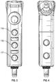
- FIG. 1 is a perspective view of a first embodiment.
- FIG. 2 is a top plan view of the first embodiment.
- FIG. 3 is a front plan view of the first embodiment.
- FIG. 4 is a back plan view of the first embodiment.
- FIG. 5 is a side plan view of the first embodiment.
- FIG. 6 is a bottom plan view of the first embodiment.
- FIG. 7 is a perspective view of the first embodiment in which the controller is held by a user.
- FIG. 8 is a perspective view of the first embodiment in which the joystick of the controller is manipulated by a user.
- FIG. 9 is a perspective view of the first embodiment showing the internal layout of the control processing electronics.
- FIG. 10 is a second side plan view of the first embodiment.
- FIG. 11 is a perspective view of a second embodiment having LED indicator lights.
- FIG. 12 is a top plan view of the second embodiment.
- FIG. 13 is a front plan view of the second embodiment.
- FIG. 14 is a back plan view of the second embodiment.
- FIG. 15 is a second side plan view of the second embodiment.
- FIG. 16 is a perspective view of a third embodiment having a palm safety activator switch.
- FIG. 17 is another perspective view of the third embodiment.
- Single Hand Controller 101 generally has an upper portion 102 and a lower portion 103 .
- Single Hand Controller 101 has a front surface 104 and back surface 105 .
- In the center of the upper surface 108 there is a lanyard hole.
- front surface 104 , back surface 105 , first side surface 106 , upper surface 108 and lower surface 109 are formed as a unitary body, to which second side surface 107 is affixed via a plurality of fixtures 110 passing through holes in the controller body.
- the fixtures 110 may be coated with an anti-tamper chemical.
- a communication interface 111 which may be a push/pull connector.
- a push/pull connector can provide emergency separation to ensure user safety.
- the communication interface may be threaded or another persistent interconnection.
- displacement of the proportional plunger produces a signal increasing linearly in strength with the amount of depression applied by the user.
- the proportional plunger may alternatively be any displacement taper, such as a logarithmic or custom taper.
- Other buttons may be employed, such as momentary switches or Single Pole Single Toggle (SPST), Double Pole Single Toggle (DPST), Double Pole Single Toggle (DPST) or Double Pole Double Toggle (DPDT).
- Switch 114 is positioned on upper surface 102 .
- Switches 115 and 116 are positioned on back surface 105 .
- Switches 115 and 116 are recessed so as to be guarded from being accidentally actuated by the palm.
- Switches 117 , 118 , and 119 are disposed on front surface 104 .
- finger separating protrusions 119 provide positive separation of the user's fingers to prevent inadvertent activation of switches, and to provide easy identification by tactile feel without needing visual confirmation.
- switches may be disposed in finger grooves.
- a protective lip 120 surrounds joystick 112 on three sides, so as to prevent inadvertent activation. Switches may be momentary press toggle, on-off toggle, rocker or spring-back toggle switches.
- the joystick may be a one, two or three axis joystick.
- the output of the joystick may have a taper.
- the joystick may have a region during initial displacement that provides fine motor control, while having beyond that a region that provides a large output for a given displacement.
- tapers may alternatively be employed.
- the single hand controller is used to control an unmanned vehicle as follows.
- the user grips the single hand controller 101 with the palm of the hand resting against the second side surface 107 , with the fingertips of the hand disposed against the front surface 104 .
- the index finger is configured to operate the proportional plunger switch 113 .
- Switch 119 is operated by the middle finger
- Switch 118 is operated by the ring finger
- Switch 117 is operated by the pinky finger.
- the thenar eminence group of muscles on the palm of the user's hand at the base of the thumb grasps the back surface 105 , whereby the user's thumb is disposed to operate joystick 112 .
- FIGS. 7-8 depict the manner in which a user may grasp the single hand controller.
- the design of the single hand controller is symmetrical, and equally suited to left and right handed operation.
- the single hand controller 101 tapers from the upper surface to the lower surface, which accommodates the decreasing size of the fingers of the user's hand, facilitating the ability of the user to grasp the control with a single hand.
- the user may enter commands with the controller as follows:
- the above functions may be reassigned or reprogrammed to different functions or to operate with other unmanned vehicles or equipment.
- the controller could be used to aim and operate a weapon system.
- the linear proportional plunger may be reprogrammed so as to have other than a proportional response, for instance a logarithmic response.
- the joystick and/or its output may optionally be locked when the proportional plunger is actuated, thereby preventing unwanted movements or outputs during plunger actuation. This may include locking the joystick and/or its output when the proportional plunger begins to be depressed or when the user's finger comes in contact with the proportional plunger.
- Switches 114 - 119 require an activation force of 0.5-1.7 lbs and provide tactile feedback.
- the linear proportional plunger requires an activation force of 3.0-3.8 lbs to fully depress.
- the joystick requires 0.1-0.45 lbs to fully traverse.
- Switches 114 - 119 traverse 0.08 in. during full depression
- the linear proportional plunger traverses 0.135-0.160 in. during full depression.
- the joystick may be displaced 13° from the center in any direction.
- FIG. 9 depicts internal control processing electronics, which may operate according to USB, RS422 and/or RS232 or any other physical or virtual data communications protocol over a any variety of electrical signaling mediums.
- USB Universal Serial Bus
- ethernet Ethernet
- internet protocol wireless, radio, etc.
- the single hand controller may be contoured for single hand operation such that an operator, for example, can operate the joystick while simultaneously operating the proportional plunger to activate a brake/gas and power over trail obstacles.
- the single hand controller is also of a size so as to be easily concealed both when stowed or in operation.
- a user may employ two single hand controllers, each in one hand, providing greater control of one piece of equipment or simultaneous control of multiple pieces of equipment.
- the single hand controller may mimic the stock of common weaponry used by military person so as to be recognizable and easy to grip.
- the single hand controller is contoured to allow a comfortable grip with the pinky, ring, and/or middle fingers, allowing full access to a joystick and proportional plunger with the thumb and pointer finger. A user may therefore operate three axes simultaneously.
- FIG. 9 details the internal structure of the single hand controller embodiment.
- FIG. 10 depicts a two piece construction for the single hand controller embodiment, wherein securement screws are inserted through the side of the controller depicted in FIG. 5 and secured to side plate 1001 .
- FIG. 11 depicts a second embodiment single hand controller embodiment, having a housing 1101 containing a first indicator light 1102 and a second indicator light 1103 .
- the illuminated surfaces of the first indicator light 1102 and second indicator light 1103 may be recessed into the housing 1101 so they are visible to the operator of the unit but less or not visible from angles such as from the side of the unit. It should be appreciated that a different number of indicator lights may also be employed. In certain embodiments, the indicator lights may indicate one or of that a break has been employed or throttle has been employed.
- FIGS. 12-15 depict additional views of the embodiment of FIG. 11 .
- FIG. 16 depicts a third embodiment having including a palm safety actuator 1601 .
- the palm safety actuator must be depressed by the user's palm to enable one or more functionalities, such that if the user drops or otherwise loses control of the single hand controller it those functionalities are automatically disabled.
- the safety actuator may be a shield that must be flipped up to gain access to a switch or button underneath.
- FIG. 16 also depicts indicator lights protruding from a housing rather than being recessed.
- FIG. 17 is another view of the embodiment of FIG. 16 .
- the width of the body of the single hand controller from one side to the other is 1.20 inches
- the distance from the most extensive surface from the back of the single hand controller to the forwardmost proportional plunger is 3.52 inches
- the height of the single hand controller from the uppermost surface to the bottom most surface excluding the communication interface is 4.47
- the height of the single hand controller from the uppermost surface to the bottom most surface of the communication interface is 5.18 inches.
- bottom”, “below”, “top” and “above” as used herein do not necessarily indicate that a “bottom” component is below a “top” component, or that a component that is “below” is indeed “below” another component or that a component that is “above” is indeed “above” another component as such directions, components or both may be flipped, rotated, moved in space, placed in a diagonal orientation or position, placed horizontally or vertically, or similarly modified. Accordingly, it will be appreciated that the terms “bottom”, “below”, “top” and “above” may be used herein for exemplary purposes only, to illustrate the relative positioning or placement of certain components, to indicate a first and a second component or to do both.
Abstract
Description
| USB Usage | USB Usage | USB Usage | ||
| Description | Page | ID | Name | |
| Joystick X Axis | 0x01 | 0x30 | X | |
| Joystick Y Axis | 0x01 | 0x31 | Y | |
| Plunger Proportional | 0x01 | 0x33 | Rx | |
| Switch 1 Palm Facing | 0x09 | 1 | Button 1 | |
| Upper | ||||
| Switch 2 Palm Facing | 0x09 | 2 | Button 2 | |
| Lower | ||||
| Switch 3 Pinky Finger | 0x09 | 3 | Button 3 | |
| | 0x09 | 4 | |
|
| Switch 5 Middle | 0x09 | 5 | Button 5 | |
| Finger | ||||
| Switch 6 Fore Finger | 0x09 | 6 | Button 6 | |
Claims (22)
Priority Applications (2)
| Application Number | Priority Date | Filing Date | Title |
|---|---|---|---|
| US16/589,327 US11114267B2 (en) | 2018-10-05 | 2019-10-01 | Single hand controller |
| PCT/US2019/054735 WO2020072927A1 (en) | 2018-10-05 | 2019-10-04 | Single hand controller |
Applications Claiming Priority (2)
| Application Number | Priority Date | Filing Date | Title |
|---|---|---|---|
| US201862742087P | 2018-10-05 | 2018-10-05 | |
| US16/589,327 US11114267B2 (en) | 2018-10-05 | 2019-10-01 | Single hand controller |
Publications (2)
| Publication Number | Publication Date |
|---|---|
| US20200111635A1 US20200111635A1 (en) | 2020-04-09 |
| US11114267B2 true US11114267B2 (en) | 2021-09-07 |
Family
ID=70052399
Family Applications (1)
| Application Number | Title | Priority Date | Filing Date |
|---|---|---|---|
| US16/589,327 Active US11114267B2 (en) | 2018-10-05 | 2019-10-01 | Single hand controller |
Country Status (2)
| Country | Link |
|---|---|
| US (1) | US11114267B2 (en) |
| WO (1) | WO2020072927A1 (en) |
Families Citing this family (4)
| Publication number | Priority date | Publication date | Assignee | Title |
|---|---|---|---|---|
| USD913253S1 (en) * | 2019-10-01 | 2021-03-16 | Measurement Systems, Inc. | Single hand controller |
| US11614766B2 (en) * | 2020-04-09 | 2023-03-28 | Caterpillar Inc. | Machine joystick with comfort and accessibility features |
| EP4188566A4 (en) * | 2020-08-03 | 2024-01-10 | Sheel Llc | Game controller apparatus and method |
| DE102022115160A1 (en) | 2022-06-17 | 2023-12-28 | Fraunhofer-Gesellschaft zur Förderung der angewandten Forschung eingetragener Verein | One-handed operating device |
Citations (27)
| Publication number | Priority date | Publication date | Assignee | Title |
|---|---|---|---|---|
| US4061988A (en) | 1976-02-09 | 1977-12-06 | Oak Industries Inc. | Hall effect linear motion switch |
| US4552360A (en) * | 1982-09-29 | 1985-11-12 | Coleco Industries, Inc. | Video game with control of movement and rate of movement of a plurality of game objects |
| US4825157A (en) | 1988-05-16 | 1989-04-25 | Mikan Peter J | Hall-effect controller |
| USD331044S (en) * | 1990-05-15 | 1992-11-17 | Std Electronic International Ltd. | Joystick |
| US5644113A (en) | 1995-01-03 | 1997-07-01 | Sega Eenterprises, Ltd. | Hand held control key device including multiple switch arrangements |
| US5923317A (en) | 1997-06-17 | 1999-07-13 | Thrustmaster, Inc. | Two-handed controller for video games and simulations |
| USD431604S (en) | 1999-11-05 | 2000-10-03 | Wah Leung Chan | Game control pad |
| US6281883B1 (en) * | 1993-03-10 | 2001-08-28 | Voice Domain Technologies, Llc | Data entry device |
| US20010020934A1 (en) | 2000-01-21 | 2001-09-13 | Izumi Fukuda | Entertainment apparatus, storage medium and operation method of manipulating object |
| US6459058B1 (en) | 1999-01-18 | 2002-10-01 | Alps Electric Co., Ltd. | Operating device having operating button adapted to slide in housing while being pushed to effect switching operation |
| US20050150750A1 (en) | 2004-01-12 | 2005-07-14 | Hsien-Ta Huang | Buffering protective handheld controller |
| US20050197178A1 (en) * | 2004-03-03 | 2005-09-08 | Villegas Ariel P. | Gun-shaped game controller |
| USD533142S1 (en) | 2004-11-17 | 2006-12-05 | Ultra Electronics Measurement Systems, Inc. | Handheld controller for vehicles |
| US20080119269A1 (en) | 2006-11-17 | 2008-05-22 | Nintendo Co., Ltd. | Game system and storage medium storing game program |
| USD589465S1 (en) * | 2007-07-27 | 2009-03-31 | Omron Corporation | Handy switch |
| US20100117953A1 (en) | 2008-11-07 | 2010-05-13 | Joseph Stute | Hand-worn interface device |
| US20100304868A1 (en) | 2009-05-29 | 2010-12-02 | Sony Computer Entertainment America Inc. | Multi-positional three-dimensional controller |
| US20150084900A1 (en) * | 2013-01-18 | 2015-03-26 | Microsoft Technology Licensing, Llc | Removable input module |
| EP2952234A1 (en) | 2014-05-23 | 2015-12-09 | Corrado Di Rofi | A control device for console-based videogames |
| US20160279514A1 (en) * | 2012-08-31 | 2016-09-29 | Blue Goji Llc | Multiple electronic control and tracking devices for mixed-reality interaction |
| US20160342218A1 (en) * | 2015-05-20 | 2016-11-24 | Survios, Inc. | Systems and methods for natural motion interaction with a virtual environment |
| US20170361222A1 (en) * | 2016-06-10 | 2017-12-21 | Nintendo Co., Ltd. | Game controller |
| US10324487B2 (en) * | 2016-10-27 | 2019-06-18 | Fluidity Technologies, Inc. | Multi-axis gimbal mounting for controller providing tactile feedback for the null command |
| US10331233B2 (en) * | 2016-10-27 | 2019-06-25 | Fluidity Technologies, Inc. | Camera and sensor controls for remotely operated vehicles and virtual environments |
| US10520973B2 (en) * | 2016-10-27 | 2019-12-31 | Fluidity Technologies, Inc. | Dynamically balanced multi-degrees-of-freedom hand controller |
| US10675546B2 (en) * | 2016-06-21 | 2020-06-09 | Hori Co., Ltd. | Controllers for game machines |
| US20200246691A1 (en) * | 2016-10-11 | 2020-08-06 | Valve Corporation | Electronic controller with finger sensing and an adjustable hand retainer |
-
2019
- 2019-10-01 US US16/589,327 patent/US11114267B2/en active Active
- 2019-10-04 WO PCT/US2019/054735 patent/WO2020072927A1/en active Application Filing
Patent Citations (27)
| Publication number | Priority date | Publication date | Assignee | Title |
|---|---|---|---|---|
| US4061988A (en) | 1976-02-09 | 1977-12-06 | Oak Industries Inc. | Hall effect linear motion switch |
| US4552360A (en) * | 1982-09-29 | 1985-11-12 | Coleco Industries, Inc. | Video game with control of movement and rate of movement of a plurality of game objects |
| US4825157A (en) | 1988-05-16 | 1989-04-25 | Mikan Peter J | Hall-effect controller |
| USD331044S (en) * | 1990-05-15 | 1992-11-17 | Std Electronic International Ltd. | Joystick |
| US6281883B1 (en) * | 1993-03-10 | 2001-08-28 | Voice Domain Technologies, Llc | Data entry device |
| US5644113A (en) | 1995-01-03 | 1997-07-01 | Sega Eenterprises, Ltd. | Hand held control key device including multiple switch arrangements |
| US5923317A (en) | 1997-06-17 | 1999-07-13 | Thrustmaster, Inc. | Two-handed controller for video games and simulations |
| US6459058B1 (en) | 1999-01-18 | 2002-10-01 | Alps Electric Co., Ltd. | Operating device having operating button adapted to slide in housing while being pushed to effect switching operation |
| USD431604S (en) | 1999-11-05 | 2000-10-03 | Wah Leung Chan | Game control pad |
| US20010020934A1 (en) | 2000-01-21 | 2001-09-13 | Izumi Fukuda | Entertainment apparatus, storage medium and operation method of manipulating object |
| US20050150750A1 (en) | 2004-01-12 | 2005-07-14 | Hsien-Ta Huang | Buffering protective handheld controller |
| US20050197178A1 (en) * | 2004-03-03 | 2005-09-08 | Villegas Ariel P. | Gun-shaped game controller |
| USD533142S1 (en) | 2004-11-17 | 2006-12-05 | Ultra Electronics Measurement Systems, Inc. | Handheld controller for vehicles |
| US20080119269A1 (en) | 2006-11-17 | 2008-05-22 | Nintendo Co., Ltd. | Game system and storage medium storing game program |
| USD589465S1 (en) * | 2007-07-27 | 2009-03-31 | Omron Corporation | Handy switch |
| US20100117953A1 (en) | 2008-11-07 | 2010-05-13 | Joseph Stute | Hand-worn interface device |
| US20100304868A1 (en) | 2009-05-29 | 2010-12-02 | Sony Computer Entertainment America Inc. | Multi-positional three-dimensional controller |
| US20160279514A1 (en) * | 2012-08-31 | 2016-09-29 | Blue Goji Llc | Multiple electronic control and tracking devices for mixed-reality interaction |
| US20150084900A1 (en) * | 2013-01-18 | 2015-03-26 | Microsoft Technology Licensing, Llc | Removable input module |
| EP2952234A1 (en) | 2014-05-23 | 2015-12-09 | Corrado Di Rofi | A control device for console-based videogames |
| US20160342218A1 (en) * | 2015-05-20 | 2016-11-24 | Survios, Inc. | Systems and methods for natural motion interaction with a virtual environment |
| US20170361222A1 (en) * | 2016-06-10 | 2017-12-21 | Nintendo Co., Ltd. | Game controller |
| US10675546B2 (en) * | 2016-06-21 | 2020-06-09 | Hori Co., Ltd. | Controllers for game machines |
| US20200246691A1 (en) * | 2016-10-11 | 2020-08-06 | Valve Corporation | Electronic controller with finger sensing and an adjustable hand retainer |
| US10324487B2 (en) * | 2016-10-27 | 2019-06-18 | Fluidity Technologies, Inc. | Multi-axis gimbal mounting for controller providing tactile feedback for the null command |
| US10331233B2 (en) * | 2016-10-27 | 2019-06-25 | Fluidity Technologies, Inc. | Camera and sensor controls for remotely operated vehicles and virtual environments |
| US10520973B2 (en) * | 2016-10-27 | 2019-12-31 | Fluidity Technologies, Inc. | Dynamically balanced multi-degrees-of-freedom hand controller |
Non-Patent Citations (2)
| Title |
|---|
| Paquette et al., unpublished Design U.S. Appl. No. 29/707,790, filed Oct. 1, 2019. |
| Switches, Grips and Operator Control Modules, OTTO Product Catalog 113 (2016). www.gsglobalresources.com/uploads/OTTO_catalog.pdf p. 24, 26, 27. |
Also Published As
| Publication number | Publication date |
|---|---|
| WO2020072927A1 (en) | 2020-04-09 |
| US20200111635A1 (en) | 2020-04-09 |
Similar Documents
| Publication | Publication Date | Title |
|---|---|---|
| US11114267B2 (en) | Single hand controller | |
| US7471216B2 (en) | Handheld controller for vehicles | |
| US5512892A (en) | Hand held control device | |
| US9870052B2 (en) | Hand-held controller with pressure-sensing switch for virtual-reality systems | |
| US8905845B2 (en) | Gaming controller system | |
| EP2900344B1 (en) | A game controller | |
| EP2674829B1 (en) | Sidestick controller grip | |
| EP3566755A1 (en) | Game controller with removable paddle accessory | |
| US20030038781A1 (en) | Joystick capable of controlling direction rudder and accelerator synchronously | |
| US20060262000A1 (en) | Portable controller for operating a device from a remote location | |
| JPH0688219B2 (en) | Portable teaching device | |
| US20200324199A1 (en) | Pedal system for gaming apparatus | |
| KR20020097024A (en) | Hand grippable combined keyboard and game controller system | |
| WO2018167464A1 (en) | Input apparatus for a games console | |
| CN108724149B (en) | Handheld robot teaching device | |
| US20190112030A1 (en) | Cockpit seat armrest avionics cursor control device | |
| CN217773196U (en) | Position adjusting structure and game paddle | |
| US8154519B2 (en) | Ergonomic hand-held computer input and control device | |
| US5764180A (en) | Remote control keypad unit | |
| US20050156889A1 (en) | User input device with pistol grip and counterweight | |
| US20090085778A1 (en) | Text input device for videogame controller | |
| EP1283535A3 (en) | Hand controller for a remote operated vehicle | |
| US7499022B2 (en) | User input device with vertical grip and scroll wheel | |
| US20190111330A1 (en) | Controllers for electric skateboards | |
| SE511969C2 (en) | Two-hand operation of working machines |
Legal Events
| Date | Code | Title | Description |
|---|---|---|---|
| FEPP | Fee payment procedure |
Free format text: ENTITY STATUS SET TO UNDISCOUNTED (ORIGINAL EVENT CODE: BIG.); ENTITY STATUS OF PATENT OWNER: LARGE ENTITY |
|
| STPP | Information on status: patent application and granting procedure in general |
Free format text: NON FINAL ACTION MAILED |
|
| AS | Assignment |
Owner name: MEASUREMENT SYSTEMS, INC., CONNECTICUT Free format text: ASSIGNMENT OF ASSIGNORS INTEREST;ASSIGNORS:PAQUETTE, RAYMOND J.;BLAIN, ROBERT A.;PHILLIPS, JEFFREY D.;AND OTHERS;SIGNING DATES FROM 20210107 TO 20210111;REEL/FRAME:054916/0695 |
|
| STPP | Information on status: patent application and granting procedure in general |
Free format text: FINAL REJECTION MAILED |
|
| STPP | Information on status: patent application and granting procedure in general |
Free format text: RESPONSE AFTER FINAL ACTION FORWARDED TO EXAMINER |
|
| STPP | Information on status: patent application and granting procedure in general |
Free format text: NOTICE OF ALLOWANCE MAILED -- APPLICATION RECEIVED IN OFFICE OF PUBLICATIONS |
|
| STPP | Information on status: patent application and granting procedure in general |
Free format text: PUBLICATIONS -- ISSUE FEE PAYMENT VERIFIED |
|
| STCF | Information on status: patent grant |
Free format text: PATENTED CASE |